EP4292486B1 - Umwandelbare handwaschstation - Google Patents
Umwandelbare handwaschstation Download PDFInfo
- Publication number
- EP4292486B1 EP4292486B1 EP23178749.0A EP23178749A EP4292486B1 EP 4292486 B1 EP4292486 B1 EP 4292486B1 EP 23178749 A EP23178749 A EP 23178749A EP 4292486 B1 EP4292486 B1 EP 4292486B1
- Authority
- EP
- European Patent Office
- Prior art keywords
- pivot
- station
- handwash
- sink unit
- handwash station
- Prior art date
- Legal status (The legal status is an assumption and is not a legal conclusion. Google has not performed a legal analysis and makes no representation as to the accuracy of the status listed.)
- Active
Links
Images


Classifications
-
- A—HUMAN NECESSITIES
- A47—FURNITURE; DOMESTIC ARTICLES OR APPLIANCES; COFFEE MILLS; SPICE MILLS; SUCTION CLEANERS IN GENERAL
- A47K—SANITARY EQUIPMENT; ACCESSORIES THEREFOR, e.g. TOILET ACCESSORIES
- A47K1/00—Wash-stands; Appurtenances therefor
- A47K1/02—Portable toilet tables; Wash cabinets or stands
-
- A—HUMAN NECESSITIES
- A47—FURNITURE; DOMESTIC ARTICLES OR APPLIANCES; COFFEE MILLS; SPICE MILLS; SUCTION CLEANERS IN GENERAL
- A47K—SANITARY EQUIPMENT; ACCESSORIES THEREFOR, e.g. TOILET ACCESSORIES
- A47K4/00—Combinations of baths, showers, sinks, wash-basins, closets, or urinals, not covered by a single other group of this subclass
-
- E—FIXED CONSTRUCTIONS
- E03—WATER SUPPLY; SEWERAGE
- E03C—DOMESTIC PLUMBING INSTALLATIONS FOR FRESH WATER OR WASTE WATER; SINKS
- E03C1/00—Domestic plumbing installations for fresh water or waste water; Sinks
- E03C1/12—Plumbing installations for waste water; Basins or fountains connected thereto; Sinks
- E03C1/18—Sinks, whether or not connected to the waste-pipe
-
- A—HUMAN NECESSITIES
- A47—FURNITURE; DOMESTIC ARTICLES OR APPLIANCES; COFFEE MILLS; SPICE MILLS; SUCTION CLEANERS IN GENERAL
- A47K—SANITARY EQUIPMENT; ACCESSORIES THEREFOR, e.g. TOILET ACCESSORIES
- A47K1/00—Wash-stands; Appurtenances therefor
- A47K1/04—Basins; Jugs; Holding devices therefor
- A47K1/05—Holding devices for basins or jugs
Definitions
- the invention relates to a handwash station and a portable restroom having a sanitary space including a handwash station.
- the handwash station is frontally accessible from a user position.
- the handwash station has a base body for supporting a pivotally connected sink unit.
- the base body has a front side, a left side and a right side.
- the sink unit has a sink and a faucet for dispensing water to the sink.
- US7730561BB discloses a portable hand-wash sink station which is sized to fit within a typical portable restroom.
- the hand-wash sink station comprises a vertically elongated used water storage tank and a fresh water tank is disposed within a central portion of the used water storage tank.
- the sink station further includes an upper column that serves as a sink top.
- the upper column includes two sink bowls which are formed in a lower portion on opposite sides of the sink station. Further, the upper column includes two faucets disposed above each sink bowl. Water is supplied from the freshwater tank to the faucets through a system which includes two foot-operated pumps to pump water through conduits when the user of the unit applies foot pressure upon the pumps.
- the upper column is attached to the used water storage tank and may be tilted with respect to the used water storage tank by a hinge.
- the upper column may be secured to the used water storage tank through the use of a latch that may be further secured through the use of a lock to resist tampering. Maintenance personnel may pivot the upper column away from the used water storage tank for inspection or replenishment of the freshwater tank.
- US4769863 discloses another hand was unit with a tank and a dispenser housing.
- the dispenser housing is pivotally connected by a hinge to an open-top container.
- a hand-wash station is to be installed inside a small mobile sanitary unit having sidewalls delimiting only a floor area of about 1.0m 2 .
- a small sanitary unit includes a toilet seat and often also a urinal.
- a problem to many known hand wash sink stations is that such an object do not properly fit in such a small sized mobile sanitary unit.
- a configuration of a hand-wash sink station is desired which provides an improved fit in a mobile sanitary unit.
- the general object of the present invention is to at least partially eliminate the above mentioned drawback and/or to provide a usable alternative. More specific, it is an object of the invention to provide a hand wash station having a configuration which provides an improved fit of the hand wash station inside a mobile sanitary unit.
- this object is achieved by a handwash station according to claim 1.
- a user stands in front of the handwash station.
- the handwash station has a front side, left side and a right side and is accessible from a user position in front of the handwash station.
- the handwash station has a planar back side for placement of the handwash station against a wall.
- the handwash station is formed by a base body and a sink unit.
- the sink unit is positioned on top of the base body.
- the sink unit is pivotally connected to the base body to allow access to an inner space of the base body.
- the inner space of the base body may include a water storage.
- an improvement is obtained by providing a handwash station which is convertible from a left to a right version.
- the sink unit is pivotable either to the left or to the right.
- the sink unit In the left version of the handwash station, the sink unit is pivotable to the left side about a left pivot.
- the sink unit In the right version of the handwash station, the sink unit is pivotable to the right side about a right pivot.
- the left pivot has a left pivot axis being situated at a left region of the handwash station, and the right pivot has a right pivot axis being situated at a right region of the handwash station.
- Each pivot includes a pivot member and a complimentary pivot member which form a pair of pivot members.
- the left and right pivot member are provided at a bottom region of the sink unit, and the left and right complementary pivot member are provided at a top region of the base body.
- Each of the left and right pivot can be formed by selectively connecting the pair of pivot members by a pivot shaft which defines the pivot axis. A selective connection of the pivot members of one of the left or right pivot by the pivot shaft determines whether a left or right version of the handwash station is obtained.
- the available selection of a left or right version of the handwash station provides an advantage in placing the handwash station inside a portable restroom.
- Portable restrooms have a minimal floor area.
- the handwash station is positioned at a front region right behind a door of the portable restroom which necessitates a backwards directed pivoting movement of the sink unit to allow maintenance.
- Due to the possibility of a left or right version the same handwash station is suitable to be placed to a left or right side wall of the portable restroom at the front region.
- the possibility to install the handwash station in a left or right version always allows the backwards directed pivoting movement of the sink unit in both situations.
- each pivot comprises a pivot shaft which is releasable from the pair of pivot members by an operator to mount or demount the pivot to convert the handwash station from the left version to the right version and vice versa.
- the pivot shaft is manually releasable without a need of a tool.
- a pivot shaft may be completely removable from the handwash station.
- the pivot shaft is slidable connected to one of the sink unit and the base body, such that the pivot shaft can be shifted out of a pivot without being completely removed from either the base body or the sink unit.
- the non-removable pivot shaft cannot be loosened from the handwash station.
- the pivot shaft is insertable into one of the left and right pivot from a back side of the base body.
- Through holes may be provided at the back side of the base body for receiving a pivot shaft to establish a connection between a pair of pivot members.
- the insertion of a pivot shaft from the backside of the base body is beneficial to keep the pivot shaft out of reach for a user.
- the conversion of the handwash station is protected against vandalism.
- the sink unit is out of centre positioned over a certain distance relative to the base body.
- the faucet for dispensing water is offset positioned from a centre line of the base body.
- the sink unit has a sink portion which in a closed position of the handwash station protrudes from side wall of the base body.
- the sink portion is a lateral portion which may be part of the sink or provide a surface besides the sink.
- the protruding sink portion may serve as a stopper of the sink unit when moving the sink unit from the closed position to an open position.
- the sink unit is rotated at least 90°, in particular about 95°, to get the sink unit in a stable position in which the sink portion abuts against a side wall of the base body.
- the stopper formed by the sink portion is beneficial in that a full access to the inner space of the base body is provided to an operator to carry out maintenance.
- the handwash station may remain free of obstructive additional items, like a chord or a link, to keep the sink unit in the open position.
- each pivot is formed by a pair of pivot members including a V-shaped pivot member and a V -shaped complimentary pivot member.
- One of the pair of pivot members is formed by a V-shaped recess for receiving a V-shaped body.
- the V-shape of a pivot member is beneficial in aligning the sink unit with respect to the supporting base body.
- the V shape contributes in positioning the sink unit when moving down onto the base body.
- the sink unit has a stack recess at a lateral side.
- the stack recess is configured to partly receive a faucet portion of another sink unit in a stack assembly.
- the faucet portion protrudes as an upper column above a sink unit.
- a sink unit can be sandwiched in between two neighbouring sink units, wherein the faucet portion of the sink unit is positioned in between stack recesses of the neighbouring sink unit.
- the faucet portion is enclosed by the neighbouring seal units which provides a protection of the faucet during transport.
- the invention relates to a portable restroom including a handwash station according to the invention.
- Portable restrooms in all kind of appearances are well known in the public area.
- the portable restroom provides a sanitary space including for example a toilet, urinal or lavatory.
- a portable restroom provided with a handwash station according to the invention is provided, wherein the handwash station has a back side which is positioned against a side wall of the sanitary space.
- a user position in front of the handwash station provides access to the sink unit of the handwash station.
- the handwash station is positioned at a corner of the sanitary space.
- the available convertibility of the handwash station allows an optimal placement in the corner of the sanitary space, wherein the sink unit is pivotable away from the base body in a direction away from the corner.
- a handwash station in an embodiment according to the invention is denoted overall by reference numeral 100.
- Identical reference signs are used in the drawings to indicate identical or functionally similar components.
- the words vertical, horizontal, longitudinal, cross-sectional and a coordinate system X,Y, Z shown in the drawings - with reference to gravity and normal placement of the hand wash station in use - are to be interpreted in a non-limiting way.
- Fig. 1-9 show the coordinate system including a X-, Y-, Z-axis.
- the Z-axis defines a vertical direction or a height of the handwash station.
- the X- and Y-axis define a XY plane which is a horizontal plane, in which the X-direction defines a depth and the Y-direction defines a lateral direction, a width of the handwash station.
- the Y- and Z-axis define a YZ-plane which is a vertical plane in width direction.
- the handwash station as shown in fig. 1-9 is suitable to be placed inside a portable restroom, in particular an outdoor portable restroom, which are typically very narrow.
- the portable restroom provides a sanitary space with a floor and a side wall.
- the handwash station is placed against the side wall.
- the handwash station is structured by components made of a plastic material, in particular by moulding, more in particular by centrifugal plastic casting.
- the handwash station 100 is accessible from a front side F.
- a user stands at a user position in front of the handwash station when washing his hands.
- the handwash station 100 has a planar back side B which is arranged to be placed against a wall.
- the handwash station 100 including the planar back is arranged to be placed inside a portable restroom against a side wall.
- the handwash station has a user operable tool for operating a faucet 3 for dispensing water.
- the handwash station has a foot pedal 11 at the front side F.
- the user may operate the foot pedal 11 or alternatively a manually operable stick or button for supplying water to the faucet 3 for dispensing water.
- the faucet 3 is positioned at a faucet portion 30 which protrudes above a sink 20 of the sink unit 2.
- the faucet portion 30 is centrally positioned adjacent the sink 20 at a back side of the sink unit.
- the handwash station 100 has a base body 1 and a sink unit 2.
- the base body 1 is arranged to support the sink unit 2.
- the base body 1 and the sink unit 2 are separate items.
- the sink unit 2 is coupled to the base body 1.
- the sink unit 2 is movable away from the base body 1.
- Each of the base body 1 and the sink unit 2 have a planar back side which are in assembly aligned with each other.
- the handwash station formed by the stacked base body 1 and sink unit 2 is suitable to be placed against a wall of a portable restroom.
- the handwash station 100 is shown in the closed position CP.
- the closed position CP is an operational configuration of the handwash station 100.
- the sink unit 2 is positioned on top of the base body 1.
- the sink unit 2 closes an inner space of the base body 1.
- the inner space of the base body 1 normally serves as a water storage.
- the inner space may form a water storage for clean and/or used water.
- Fig. 2 shows a left and right version LV, RV of the handwash station 100.
- the handwash station 100 includes an improvement in that the handwash station 100 is convertible from a left to a right version LV, RV and vice versa.
- the sink unit 2 is pivotable about a left pivot 4 having a pivot axis 04 being positioned at a left region of the handwash station.
- the sink unit 2 is pivotable about a right pivot 5 having a pivot axis 05 which is positioned at a right region of the handwash station.
- the sink unit 2 is positioned out of centre relative to the base body 1 over a distance 'd' to the left.
- a sink portion 8 of the sink unit 2 protrudes at a left region from a side wall of the base body 1.
- the right version RV of the handwash station 100 is obtained by an out of centre positioning of the sink unit 2 relative to the base body 1 over a distance 'd' to the right.
- a sink portion 8 protrudes at a right region from the base body 1.
- the sink portion 8 is a portion of the sink unit 2 which may include a portion of the sink 20.
- Fig. 3 shows the left version LV of the handwash station 100 in an open position OP.
- a maintenance to the handwash station can be carried out.
- an access is provided to the inner space of the base body 1.
- An operator may empty or replenish a water storage inside the base body 1.
- the sink unit 2 is pivoted to the left L about the left pivot 4 having a left pivot axis 04 situated in a left region of the base body 1.
- the sink unit 2 is pivoted about an angle of at least 90°, in particular about 95°, and has obtained a stable position in which the sink portion 8 abuts against a left side wall of the base body 1.
- a right pivot member 51 is visible which is decoupled from a complementary right pivot member 52 at the base body 1.
- Fig. 4-8 show several views of the right version RV of the handwash station 100 in an open position OP.
- the sink unit 2 In the open position OP, the sink unit 2 is pivoted about a right pivot axis 05 to the right side R.
- the sink unit 2 is pivoted about an angle of at least 90° and has obtained a stable position in which the sink portion 8 abuts against a right side wall of the base body 1.
- the left pivot member 41 is visible which is decoupled from a complementary left pivot member 42 at the base body 1.
- both pivot members 41, 42 have a V-shape.
- the left pivot member 41 has a downwardly tapered shape.
- the left pivot member 41 is to be received in the complementary left pivot member 42 which is formed by a V-shaped recess which has an upwardly tapered shape.
- a through hole 43, 53 extending in the frontal direction is provided in the first and second pivot member 41, 51 for receiving a pivot shaft (not shown).
- the complementary pivot members 42, 52 have complementary holes for receiving the shaft. By mounting the shaft, a selective pivot member 41, 51 can be coupled to the complementary left pivot member 42, 52.
- Fig. 9 shows a rear view of the left version LV the handwash station 100 in the open position OP in which the sink unit 2 is rotated about the left pivot axis 04.
- the complementary through holes 43, 53 defining the left and right pivot axes 04, 05 are visible from the rear of the handwash station.
- An operator may mount or demount the pivot shaft from the backside B of the handwash station to convert the handwash station to the left or right version LV, RV.
- the left pivot 4 defining the left pivot axis 04 is functionally coupled.
- the right pivot member 51 is decoupled from its complementary right pivot member 52 which renders the right pivot axis 05 out of function.
- Fig. 10 shows the sink unit 2 in a perspective view.
- the sink unit 2 can be manufactured by blow moulding.
- the sink unit 2 has a sink 20 which is formed by a recess having a peripheral wall forming an outer contour of the sink unit.
- the sink unit has a faucet portion 30 protruding from the sink 20.
- a faucet 3 is mounted to the faucet portion 30 and extends from the faucet portion 32 to a centre region of the sink 20.
- the sink unit 2 is provided with a stack recess 9.
- the stack recess 9 contributes to obtain a stable stack assembly for transport.
- the stack recess 9 of a particular sink unit is configured for partially receiving a faucet portion 30 of another sink unit in the stack assembly.
- the faucet portion 30 is positioned in between two stack recesses of neighbouring sink units.
- the faucet 3 is positioned in a protective manner to prevent damages to the faucet 3.
- Fig. 13 and 14 show a portable restroom 200 for providing a sanitary unit at an outdoor location.
- the portable restroom has a cabin including a left and right side wall 210, 211, a rear wall 212, a door 220, a bottom 230, and a roof 240.
- the cabin forms a sanitary space.
- the sanitary space is accessible for a user.
- the portable restroom is arranged to provide an outdoor sanitary unit in a public area.
- the bottom 230 has a pallet shape including two lower apertures for receiving forks of a forklift.
- the pallet-shaped bottom 230 allows an easy transport of the portable restroom.
- the bottom 230 provides a floor 231 inside the cabin. Typically, the floor has a floor area of about 1.0m 2 .
- a toilet 300 is situated against the rear wall 212.
- the left and right side wall 210, 211 are available for a placement of the convertible handwash station as shown in figures 1-9 .
- the handwash station 100 is positioned -seen from the rear wall- against the left sidewall 210 in the left version LV of the handwash station.
- the sink unit 2 is pivotable away from the door 220.
- the handwash station 100 is positioned -seen from the rear wall- against the right side wall 211 in the right version RV of the handwash station.
- the sink unit 2 is also pivotable away from the door 220.
- the convertibility of the handwash station allows a placement of the same handwash station against a selective left or right side wall 210, 211.
- the selective left or right version always enables a pivotable release of the sink unit for maintenance.
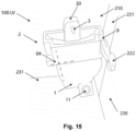
- Fig. 15 shows the left version LV of the handwash station 100 as shown in fig. 13 in an enlarged view.
- the handwash station 100 has a pivot axis 04 enabling the sink unit 2 to pivot to the left.
- the sink unit still has a stack recess 9 at a side portion at a front region of the sink unit 2.
- the stacked recess 9 at the front region is beneficial to provide a space allowing a door latch 222 to tumble behind a door frame 221.
- an alternative embodiment of the handwash station may comprise a centrally positioned sink unit on top of the base body without having a protruding sink portion at a lateral side of the base body.
- the invention provides a handwash station and a portable restroom provided with such a handwash station, wherein the handwash station is frontally accessible from a user position, in which the hand-wash station has a base body including a front side, left side, and right side, which base body supports a pivotally connected sink unit including a sink and a faucet for dispensing water.
- the handwash station is convertible from a left to a right version. In the left version, the sink unit is pivotable to the left side about a left pivot, and in the right version, the sink unit is pivotable to the right side about a right pivot. Due to the convertibility, the same handwash station is suitable to be placed either against a left or a right side wall of a portable restroom.
Landscapes
- Health & Medical Sciences (AREA)
- Public Health (AREA)
- Engineering & Computer Science (AREA)
- Environmental & Geological Engineering (AREA)
- Life Sciences & Earth Sciences (AREA)
- Hydrology & Water Resources (AREA)
- Water Supply & Treatment (AREA)
- Sink And Installation For Waste Water (AREA)
Claims (11)
- Handwaschstation (100), die von einer Benutzerposition aus frontal zugänglich ist, wobei die Handwaschstation einen Grundkörper (1) mit einer Vorderseite (F), einer linken Seite (L) und einer rechten Seite (R) aufweist, wobei der Grundkörper (1) eine schwenkbar verbundene Spülbeckeneinheit (2) trägt, die ein Spülbecken (20) und einen Wasserhahn (3) zur Wasserabgabe umfasst, dadurch gekennzeichnet, dass die Handwaschstation (100) von einer linken in eine rechte Ausführung (LV, RV) umwandelbar ist, wobei in der linken Ausführung (LV) die Spüleinheit (2) um einen linken Drehpunkt (4) auf die linke Seite (L) schwenkbar ist, und wobei in der rechten Ausführung (RV) die Spüleinheit (2) um einen rechten Drehpunkt (5) auf die rechte Seite (R) schwenkbar ist.
- Handwaschstation (100) nach Anspruch 1, wobei jeder Drehpunkt (4, 5) eine Drehwelle (43, 53) umfasst, die von einem Bediener lösbar ist, um den Drehpunkt (4, 5) selektiv zu montieren oder zu demontieren und so die Handwaschstation von der linken Version in die rechte Version und umgekehrt umzuwandeln.
- Handwaschstation (100) nach Anspruch 1 oder 2, wobei die Schwenkwelle (43, 53) ein nicht abnehmbares Teil ist, wobei die Schwenkwelle (53) verschiebbar mit der Spüle (2) oder dem Grundkörper (1) verbunden ist, um zum Anbringen bzw. Abnehmen des Schwenkzapfens in den Schwenkzapfen (4, 5) hinein oder aus diesem heraus verschoben zu werden.
- Handwaschstation (100) nach einem der vorhergehenden Ansprüche, wobei die Schwenkwelle (43, 53) von einer Rückseite (B) des Grundkörpers (1) aus in einen der linken und rechten Schwenkzapfen (4, 5) einsteckbar ist.
- Handwaschstation (100) nach einem der vorhergehenden Ansprüche, wobei in der linken und/oder rechten Ausführung die Spüleinheit (2) über eine Distanz 'd' außermittig zum Grundkörper positioniert ist.
- Handwaschstation (100) nach Anspruch 5, wobei die Spüleinheit (2) einen seitlichen Abschnitt (8) aufweist, der in einer geschlossenen Position (CP) der Handwaschstation (100) von einer Seitenwand des Grundkörpers (1) hervorsteht.
- Handwaschstation (100) gemäß Anspruch 6, wobei in einer geöffneten Position (OP) der Handwaschstation (100) die Spüleinheit (2) um einen Winkel von mindestens 90° geschwenkt ist, wobei der Spülabschnitt (8) an einer Seitenwand des Grundkörpers (1) anliegt.
- Handwaschstation (100) nach einem der vorhergehenden Ansprüche, wobei jeder Drehpunkt (4, 5) durch ein Paar Drehelemente gebildet wird, wobei sowohl das Drehelement (41, 51) als auch das komplementäre Drehelement (42, 52) eine V-Form aufweisen.
- Handwaschstation (100) nach einem der vorhergehenden Ansprüche, wobei die Spüleinheit (2) an einer Seite eine Stapelvertiefung (9) aufweist, die dazu ausgebildet ist, einen Wasserhahnabschnitt (30) einer anderen Spüleinheit (2) in einer Stapelanordnung teilweise aufzunehmen.
- Mobile Toilette (200) zum Bereitstellen einer Sanitäreinheit an einem Standort im Freien, wobei die mobile Toilette einen für einen Benutzer zugänglichen Sanitärraum aufweist, der durch einen Boden (231) und eine Seitenwand (210, 211) gebildet wird, wobei eine Handwaschstation (100) gemäß einem der vorhergehenden Ansprüche an einer ausgewählten Seitenwand des Sanitärraums positioniert ist.
- Mobile Toilette (200) nach Anspruch 10, wobei die Toilette eine Tür 220 mit einem Türriegel (222) zum Verriegeln der Tür hinter einem Türrahmen (221) umfasst, wobei die Spüle (2) an einem vorderen Bereich eine Stapelvertiefung (9) aufweist, die Platz zum Aufnehmen des Türriegels (221) bietet.
Applications Claiming Priority (1)
| Application Number | Priority Date | Filing Date | Title |
|---|---|---|---|
| NL2032141A NL2032141B1 (en) | 2022-06-13 | 2022-06-13 | Convertible handwash station |
Publications (3)
| Publication Number | Publication Date |
|---|---|
| EP4292486A1 EP4292486A1 (de) | 2023-12-20 |
| EP4292486C0 EP4292486C0 (de) | 2025-03-26 |
| EP4292486B1 true EP4292486B1 (de) | 2025-03-26 |
Family
ID=82850277
Family Applications (1)
| Application Number | Title | Priority Date | Filing Date |
|---|---|---|---|
| EP23178749.0A Active EP4292486B1 (de) | 2022-06-13 | 2023-06-12 | Umwandelbare handwaschstation |
Country Status (3)
| Country | Link |
|---|---|
| US (1) | US12349843B2 (de) |
| EP (1) | EP4292486B1 (de) |
| NL (1) | NL2032141B1 (de) |
Family Cites Families (7)
| Publication number | Priority date | Publication date | Assignee | Title |
|---|---|---|---|---|
| US1405205A (en) * | 1922-01-31 | Washbasin | ||
| US4718131A (en) * | 1986-07-28 | 1988-01-12 | Toto Ltd. | Sanitary facility unit |
| US4769863A (en) | 1987-06-19 | 1988-09-13 | Satellite Industries, Inc. | Hand wash unit |
| DE3911149C1 (en) * | 1989-04-06 | 1990-10-04 | Hendrik Emst Nl Kreeft | Mobile washing unit for hospital rooms |
| US7730561B2 (en) | 2006-02-28 | 2010-06-08 | Polyjohn Enterprises Corporation | Used water removal system for a portable, hand-wash sink station |
| KR100712147B1 (ko) * | 2006-03-10 | 2007-04-27 | 에어컨뉴스닷컴 주식회사 | 이동식 세면대 |
| US8239982B2 (en) * | 2007-11-05 | 2012-08-14 | Fryan Hassan Mohammed S | Openable twin tank flush box using recycled water |
-
2022
- 2022-06-13 NL NL2032141A patent/NL2032141B1/en active
-
2023
- 2023-06-12 EP EP23178749.0A patent/EP4292486B1/de active Active
- 2023-06-13 US US18/208,935 patent/US12349843B2/en active Active
Also Published As
| Publication number | Publication date |
|---|---|
| NL2032141B1 (en) | 2023-12-20 |
| EP4292486C0 (de) | 2025-03-26 |
| US20230397771A1 (en) | 2023-12-14 |
| US12349843B2 (en) | 2025-07-08 |
| EP4292486A1 (de) | 2023-12-20 |
Similar Documents
| Publication | Publication Date | Title |
|---|---|---|
| US9340963B2 (en) | Transportable restroom | |
| US6507958B1 (en) | Multi-function base unit for portable stand-alone restroom facility | |
| CA1315491C (en) | Sanitary fixtures | |
| US20230136174A1 (en) | Hand wash station | |
| US20140325921A1 (en) | Mobile sanitary unit for accommodating at least two sanitary facilites | |
| US20210259485A1 (en) | Toilet seat support device for a portable toilet system | |
| WO2019137592A1 (en) | An open top portable pissoir unit | |
| EP4292486A1 (de) | Umwandelbare handwaschstation. | |
| CA2400542C (en) | Portable restroom having molded base assembly with internal tank | |
| CN111601937B (zh) | 可运输的卫生单元 | |
| US6782561B2 (en) | Standardized recreational vehicle sanitary system | |
| MX2008008666A (es) | Carter de proteccion y enmascaramiento de un inodoro e inodoro asi equipado. | |
| US12342966B2 (en) | Outdoor sanitation system including an urinal unit for temporary placement and frequent transport | |
| US7104436B2 (en) | Multiple component mailbox having postal and newspaper compartments | |
| US10925445B1 (en) | Toilet seat support device for a portable toilet system | |
| EP2521819B1 (de) | Sanitärraum | |
| US20210206559A1 (en) | Liner dispenser | |
| NL2024340B1 (en) | Sanitation system and transport method. | |
| US20050283893A1 (en) | Bench-type waste transfer arrangement | |
| JPH11239659A (ja) | パチンコ機設置島 | |
| KR101744028B1 (ko) | 발효물질 분사 기능을 구비한 이동식 화장실 | |
| WO2008064416A1 (en) | Portable toilet or restroom structures | |
| EP1423573B1 (de) | Spülkastenanordnung und spülkasten | |
| ITBA980016U1 (it) | Sedile portatile per vasi igienici. | |
| JP3196485U (ja) | 着脱固定具及びこれを備える仮設トイレ |
Legal Events
| Date | Code | Title | Description |
|---|---|---|---|
| PUAI | Public reference made under article 153(3) epc to a published international application that has entered the european phase |
Free format text: ORIGINAL CODE: 0009012 |
|
| STAA | Information on the status of an ep patent application or granted ep patent |
Free format text: STATUS: THE APPLICATION HAS BEEN PUBLISHED |
|
| AK | Designated contracting states |
Kind code of ref document: A1 Designated state(s): AL AT BE BG CH CY CZ DE DK EE ES FI FR GB GR HR HU IE IS IT LI LT LU LV MC ME MK MT NL NO PL PT RO RS SE SI SK SM TR |
|
| STAA | Information on the status of an ep patent application or granted ep patent |
Free format text: STATUS: REQUEST FOR EXAMINATION WAS MADE |
|
| 17P | Request for examination filed |
Effective date: 20240610 |
|
| RBV | Designated contracting states (corrected) |
Designated state(s): AL AT BE BG CH CY CZ DE DK EE ES FI FR GB GR HR HU IE IS IT LI LT LU LV MC ME MK MT NL NO PL PT RO RS SE SI SK SM TR |
|
| GRAP | Despatch of communication of intention to grant a patent |
Free format text: ORIGINAL CODE: EPIDOSNIGR1 |
|
| STAA | Information on the status of an ep patent application or granted ep patent |
Free format text: STATUS: GRANT OF PATENT IS INTENDED |
|
| INTG | Intention to grant announced |
Effective date: 20241018 |
|
| GRAS | Grant fee paid |
Free format text: ORIGINAL CODE: EPIDOSNIGR3 |
|
| GRAA | (expected) grant |
Free format text: ORIGINAL CODE: 0009210 |
|
| STAA | Information on the status of an ep patent application or granted ep patent |
Free format text: STATUS: THE PATENT HAS BEEN GRANTED |
|
| AK | Designated contracting states |
Kind code of ref document: B1 Designated state(s): AL AT BE BG CH CY CZ DE DK EE ES FI FR GB GR HR HU IE IS IT LI LT LU LV MC ME MK MT NL NO PL PT RO RS SE SI SK SM TR |
|
| REG | Reference to a national code |
Ref country code: GB Ref legal event code: FG4D |
|
| REG | Reference to a national code |
Ref country code: CH Ref legal event code: EP |
|
| REG | Reference to a national code |
Ref country code: DE Ref legal event code: R096 Ref document number: 602023002554 Country of ref document: DE |
|
| REG | Reference to a national code |
Ref country code: IE Ref legal event code: FG4D |
|
| U01 | Request for unitary effect filed |
Effective date: 20250402 |
|
| U07 | Unitary effect registered |
Designated state(s): AT BE BG DE DK EE FI FR IT LT LU LV MT NL PT RO SE SI Effective date: 20250410 |
|
| PG25 | Lapsed in a contracting state [announced via postgrant information from national office to epo] |
Ref country code: RS Free format text: LAPSE BECAUSE OF FAILURE TO SUBMIT A TRANSLATION OF THE DESCRIPTION OR TO PAY THE FEE WITHIN THE PRESCRIBED TIME-LIMIT Effective date: 20250626 |
|
| PG25 | Lapsed in a contracting state [announced via postgrant information from national office to epo] |
Ref country code: NO Free format text: LAPSE BECAUSE OF FAILURE TO SUBMIT A TRANSLATION OF THE DESCRIPTION OR TO PAY THE FEE WITHIN THE PRESCRIBED TIME-LIMIT Effective date: 20250626 |
|
| PG25 | Lapsed in a contracting state [announced via postgrant information from national office to epo] |
Ref country code: HR Free format text: LAPSE BECAUSE OF FAILURE TO SUBMIT A TRANSLATION OF THE DESCRIPTION OR TO PAY THE FEE WITHIN THE PRESCRIBED TIME-LIMIT Effective date: 20250326 |
|
| PG25 | Lapsed in a contracting state [announced via postgrant information from national office to epo] |
Ref country code: GR Free format text: LAPSE BECAUSE OF FAILURE TO SUBMIT A TRANSLATION OF THE DESCRIPTION OR TO PAY THE FEE WITHIN THE PRESCRIBED TIME-LIMIT Effective date: 20250627 |
|
| U20 | Renewal fee for the european patent with unitary effect paid |
Year of fee payment: 3 Effective date: 20250625 |
|
| PG25 | Lapsed in a contracting state [announced via postgrant information from national office to epo] |
Ref country code: SM Free format text: LAPSE BECAUSE OF FAILURE TO SUBMIT A TRANSLATION OF THE DESCRIPTION OR TO PAY THE FEE WITHIN THE PRESCRIBED TIME-LIMIT Effective date: 20250326 |
|
| PG25 | Lapsed in a contracting state [announced via postgrant information from national office to epo] |
Ref country code: ES Free format text: LAPSE BECAUSE OF FAILURE TO SUBMIT A TRANSLATION OF THE DESCRIPTION OR TO PAY THE FEE WITHIN THE PRESCRIBED TIME-LIMIT Effective date: 20250326 |
|
| PG25 | Lapsed in a contracting state [announced via postgrant information from national office to epo] |
Ref country code: PL Free format text: LAPSE BECAUSE OF FAILURE TO SUBMIT A TRANSLATION OF THE DESCRIPTION OR TO PAY THE FEE WITHIN THE PRESCRIBED TIME-LIMIT Effective date: 20250326 |
|
| PG25 | Lapsed in a contracting state [announced via postgrant information from national office to epo] |
Ref country code: SK Free format text: LAPSE BECAUSE OF FAILURE TO SUBMIT A TRANSLATION OF THE DESCRIPTION OR TO PAY THE FEE WITHIN THE PRESCRIBED TIME-LIMIT Effective date: 20250326 |
|
| PG25 | Lapsed in a contracting state [announced via postgrant information from national office to epo] |
Ref country code: IS Free format text: LAPSE BECAUSE OF FAILURE TO SUBMIT A TRANSLATION OF THE DESCRIPTION OR TO PAY THE FEE WITHIN THE PRESCRIBED TIME-LIMIT Effective date: 20250726 |
|
| PG25 | Lapsed in a contracting state [announced via postgrant information from national office to epo] |
Ref country code: CZ Free format text: LAPSE BECAUSE OF FAILURE TO SUBMIT A TRANSLATION OF THE DESCRIPTION OR TO PAY THE FEE WITHIN THE PRESCRIBED TIME-LIMIT Effective date: 20250326 |
|
| PG25 | Lapsed in a contracting state [announced via postgrant information from national office to epo] |
Ref country code: MC Free format text: LAPSE BECAUSE OF FAILURE TO SUBMIT A TRANSLATION OF THE DESCRIPTION OR TO PAY THE FEE WITHIN THE PRESCRIBED TIME-LIMIT Effective date: 20250326 |
|
| PLBE | No opposition filed within time limit |
Free format text: ORIGINAL CODE: 0009261 |
|
| STAA | Information on the status of an ep patent application or granted ep patent |
Free format text: STATUS: NO OPPOSITION FILED WITHIN TIME LIMIT |
|
| REG | Reference to a national code |
Ref country code: CH Ref legal event code: L10 Free format text: ST27 STATUS EVENT CODE: U-0-0-L10-L00 (AS PROVIDED BY THE NATIONAL OFFICE) Effective date: 20260211 |
|
| 26N | No opposition filed |
Effective date: 20260105 |
|
| PG25 | Lapsed in a contracting state [announced via postgrant information from national office to epo] |
Ref country code: IE Free format text: LAPSE BECAUSE OF NON-PAYMENT OF DUE FEES Effective date: 20250612 |