EP4291810B1 - Verdichteranordnung mit reduziertem prozessgasverbrauch - Google Patents
Verdichteranordnung mit reduziertem prozessgasverbrauch Download PDFInfo
- Publication number
- EP4291810B1 EP4291810B1 EP22703346.1A EP22703346A EP4291810B1 EP 4291810 B1 EP4291810 B1 EP 4291810B1 EP 22703346 A EP22703346 A EP 22703346A EP 4291810 B1 EP4291810 B1 EP 4291810B1
- Authority
- EP
- European Patent Office
- Prior art keywords
- compressor
- seal
- mechanical seal
- sealing
- barrier fluid
- Prior art date
- Legal status (The legal status is an assumption and is not a legal conclusion. Google has not performed a legal analysis and makes no representation as to the accuracy of the status listed.)
- Active
Links
Images

Classifications
-
- F—MECHANICAL ENGINEERING; LIGHTING; HEATING; WEAPONS; BLASTING
- F16—ENGINEERING ELEMENTS AND UNITS; GENERAL MEASURES FOR PRODUCING AND MAINTAINING EFFECTIVE FUNCTIONING OF MACHINES OR INSTALLATIONS; THERMAL INSULATION IN GENERAL
- F16J—PISTONS; CYLINDERS; SEALINGS
- F16J15/00—Sealings
- F16J15/16—Sealings between relatively-moving surfaces
- F16J15/34—Sealings between relatively-moving surfaces with slip-ring pressed against a more or less radial face on one member
- F16J15/3404—Sealings between relatively-moving surfaces with slip-ring pressed against a more or less radial face on one member and characterised by parts or details relating to lubrication, cooling or venting of the seal
-
- F—MECHANICAL ENGINEERING; LIGHTING; HEATING; WEAPONS; BLASTING
- F04—POSITIVE - DISPLACEMENT MACHINES FOR LIQUIDS; PUMPS FOR LIQUIDS OR ELASTIC FLUIDS
- F04D—NON-POSITIVE-DISPLACEMENT PUMPS
- F04D29/00—Details, component parts, or accessories
- F04D29/08—Sealings
- F04D29/10—Shaft sealings
- F04D29/12—Shaft sealings using sealing-rings
- F04D29/122—Shaft sealings using sealing-rings especially adapted for elastic fluid pumps
- F04D29/124—Shaft sealings using sealing-rings especially adapted for elastic fluid pumps with special means for adducting cooling or sealing fluid
-
- F—MECHANICAL ENGINEERING; LIGHTING; HEATING; WEAPONS; BLASTING
- F16—ENGINEERING ELEMENTS AND UNITS; GENERAL MEASURES FOR PRODUCING AND MAINTAINING EFFECTIVE FUNCTIONING OF MACHINES OR INSTALLATIONS; THERMAL INSULATION IN GENERAL
- F16J—PISTONS; CYLINDERS; SEALINGS
- F16J15/00—Sealings
- F16J15/16—Sealings between relatively-moving surfaces
- F16J15/34—Sealings between relatively-moving surfaces with slip-ring pressed against a more or less radial face on one member
- F16J15/3404—Sealings between relatively-moving surfaces with slip-ring pressed against a more or less radial face on one member and characterised by parts or details relating to lubrication, cooling or venting of the seal
- F16J15/3408—Sealings between relatively-moving surfaces with slip-ring pressed against a more or less radial face on one member and characterised by parts or details relating to lubrication, cooling or venting of the seal at least one ring having an uneven slipping surface
- F16J15/3412—Sealings between relatively-moving surfaces with slip-ring pressed against a more or less radial face on one member and characterised by parts or details relating to lubrication, cooling or venting of the seal at least one ring having an uneven slipping surface with cavities
-
- F—MECHANICAL ENGINEERING; LIGHTING; HEATING; WEAPONS; BLASTING
- F16—ENGINEERING ELEMENTS AND UNITS; GENERAL MEASURES FOR PRODUCING AND MAINTAINING EFFECTIVE FUNCTIONING OF MACHINES OR INSTALLATIONS; THERMAL INSULATION IN GENERAL
- F16J—PISTONS; CYLINDERS; SEALINGS
- F16J15/00—Sealings
- F16J15/16—Sealings between relatively-moving surfaces
- F16J15/34—Sealings between relatively-moving surfaces with slip-ring pressed against a more or less radial face on one member
- F16J15/3404—Sealings between relatively-moving surfaces with slip-ring pressed against a more or less radial face on one member and characterised by parts or details relating to lubrication, cooling or venting of the seal
- F16J15/3408—Sealings between relatively-moving surfaces with slip-ring pressed against a more or less radial face on one member and characterised by parts or details relating to lubrication, cooling or venting of the seal at least one ring having an uneven slipping surface
- F16J15/3412—Sealings between relatively-moving surfaces with slip-ring pressed against a more or less radial face on one member and characterised by parts or details relating to lubrication, cooling or venting of the seal at least one ring having an uneven slipping surface with cavities
- F16J15/342—Sealings between relatively-moving surfaces with slip-ring pressed against a more or less radial face on one member and characterised by parts or details relating to lubrication, cooling or venting of the seal at least one ring having an uneven slipping surface with cavities with means for feeding fluid directly to the face
Definitions
- the present invention relates to a compressor arrangement with a compressor and preferably exactly one mechanical seal, which has a significantly reduced process gas consumption.
- compressor arrangements are known from the prior art in various designs.
- compressor arrangements 1 as shown in Fig. 1 shown, a compressor 2 and a mechanical seal assembly 3.
- the mechanical seal assembly 3 comprises a mechanical seal 4 with a stationary seal ring 41 and a rotating seal ring 42 as well as a labyrinth seal 30.
- the labyrinth seal 30 is arranged in the axial direction XX between the compressor 2 and the mechanical seal 4.
- Process gas is taken from the pressure area of the compressor 2 as the seal gas and fed into a seal gas line 70.
- the extracted process gas is then filtered, treated, heated and brought to a seal gas pressure by means of a booster in a treatment unit 10 and then fed into a space 11 between the mechanical seal 4 and the labyrinth seal 3.
- the labyrinth seal 30 has a gap 31 to a shaft 5. This gap 31 has a radial width of approximately 200 ⁇ m.
- This arrangement of Fig. 1 has proven itself in principle.
- One problem, however, is the relatively high process gas consumption, which is usually in the range of 1,000 to 10,000 standard liters per minute.
- the process gas is fed back into the compressor chamber. Via the mechanical seal 4, as shown in Fig. 1 indicated by the small arrows, a small leakage to the atmosphere 6.
- the compressor arrangement according to the invention with the features of claim 1 has the advantage that the overall efficiency of a compressor arrangement can be significantly increased. Furthermore, the amount of process gas used as barrier fluid for a mechanical seal arrangement can be significantly reduced. Furthermore, the mechanical seal arrangement can enable sealing with just a single seal, namely a mechanical seal.
- the compressor arrangement has a compressor for compressing the process gas from a suction region to a pressure region and a mechanical seal arrangement.
- the mechanical seal arrangement is designed to seal a shaft of the compressor against the atmosphere.
- the mechanical seal arrangement comprises a mechanical seal with a stationary seal ring having a first sliding surface and a rotating seal ring having a second sliding surface. The two seal rings define a sealing gap between their sliding surfaces.
- a barrier fluid supply is provided with a barrier fluid line, which leads from the pressure area of the compressor to the mechanical seal and through which process gas is branched off from the main flow of the compressor as barrier fluid.
- the stationary seal ring has a through-opening which runs from a rear side of the stationary seal ring to an opening on the first sliding surface of the stationary seal ring in order to supply process gas from the barrier fluid line through the stationary seal ring to the sealing gap.
- the barrier gas used as a barrier fluid is guided through the stationary seal ring directly to the sealing gap and thus exits at the sliding surface of the stationary seal ring, two sealing areas are created at the sealing gap during operation, namely one radially above the mouth of the through-hole and one radially inside the mouth of the through-hole.
- the sealing area below the mouth provides the seal to the atmosphere side
- the sealing area above the mouth of the through-hole provides the seal to the compressor.
- at least one of the sealing areas, in particular the sealing area sealing to the compressor is groove-free, i.e., without grooves or other depressions.
- the sealing gap between the sliding surfaces of the seal rings is only a few ⁇ m, in particular ⁇ 10 ⁇ m, the amount of barrier fluid required during operation of the mechanical seal arrangement can be significantly reduced.
- the sealing gap at the labyrinth seal, which second seal of the mechanical seal arrangement of the prior art approximately 200 ⁇ m.
- the gap can be reduced by a factor of 20 or more in the present invention compared to the prior art.
- additional devices for the barrier fluid supply can also be designed significantly smaller than in the prior art. This particularly applies to treatment units which, for example, have a filter, a heater and/or a cooler, and a booster.
- Another major advantage of the invention is that the axial length of the mechanical seal assembly can be reduced by eliminating the labyrinth seal. This results in a reduced overall length of the compressor assembly, which leads to significant cost savings potential for compressor manufacturers.
- the through-opening opens radially outside a mean diameter of the sealing gap at the first sliding surface of the stationary seal ring.
- the length of the sealing gap in the radial direction above the through-opening is smaller than in the radial direction below the through-opening.
- the through-opening opens at the first sliding surface of the stationary seal ring in such a way that the sealing gap is divided in a ratio of 1/3 above the opening to 2/3 below the opening.
- the first sliding surface has a circumferential groove.
- the circumferential groove is formed as a recess in the first sliding surface of the stationary sliding ring, so that the barrier fluid supplied through the passage opening through the stationary sliding ring is distributed in the circumferential direction of the sliding surface.
- the passage opening in the stationary sliding ring opens into the circumferential groove.
- the second sliding surface of the rotating seal ring has a plurality of conveying grooves. This further improves the distribution of the barrier fluid in the sealing gap and reduces leakage to the atmosphere.
- the conveying grooves in the second sliding surface of the rotating seal ring are preferably located radially inside the mouth of the through opening on the stationary seal ring.
- the mechanical seal further comprises a thrust ring with a bore, wherein the thrust ring is arranged on the rear side of the stationary seal ring.
- the barrier fluid can thus be supplied through the bore in the thrust ring to the through-opening in the stationary seal ring.
- the thrust ring preferably has a secondary seal on each of its outer and inner circumferences, in particular an O-ring.
- the pressure ring is further preloaded in the axial direction by means of a preloading device.
- a maximum of 50 to 100 standard liters per minute of process gas is diverted from the compressor as a barrier fluid and fed to the mechanical seal via the barrier fluid line.
- this allows a reduction of the diverted amount of process gas by a factor of 20 to 100. This results in significant savings in diverted barrier fluid, which can significantly increase the efficiency of the compressor in the compressor arrangement.
- the sealing gap between the rotating and the stationary seal ring preferably has a width in the axial direction which is ⁇ 10 ⁇ m, in particular ⁇ 5 ⁇ m.
- the compressor arrangement does not have a labyrinth seal and has a mechanical seal as the sole main seal.
- the compressor arrangement it is possible for the compressor arrangement to be sealed with only a single mechanical seal as the main seal.
- some secondary seals in particular O-rings or the like, to be provided on the single mechanical seal to seal the components of the mechanical seal.
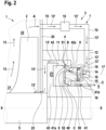
- the compressor arrangement 1 comprises a compressor 2 and a sealing arrangement with a mechanical seal arrangement 3.
- the mechanical seal arrangement 3 is designed to seal the compressor 2 on a shaft 5 against an atmosphere 6.
- the mechanical seal assembly 3 comprises a single mechanical seal 4 and a barrier fluid supply 7.
- the mechanical seal 4 comprises a stationary seal ring 41 with a first sliding surface 41a and a rotating seal ring 42 with a second sliding surface 42a.
- a sealing gap 40 is defined between the first sliding surface 41a and the second sliding surface 42a.
- the rotating slide ring 42 is fixed to the shaft 5 by means of a slide ring carrier 43 and rotates together with the shaft 5.
- the compressor 2 compresses a process gas 13 from a suction area 21 to a pressure area 22 to a predetermined pressure level.
- a barrier fluid line 70 branches off process gas, which is used in the mechanical seal arrangement as barrier fluid 13', from the pressure area 22. This is in Fig. 2 indicated by arrow A.
- the barrier fluid line 70 leads to a treatment unit 10, which, for example, has a filter, a heater and/or a cooling unit and/or a booster for additional compression of the barrier fluid.
- the barrier fluid line 70 then leads through a housing 12 to a rear side 41b of the stationary seal ring 41.
- the mechanical seal 4 is a gas-lubricated mechanical seal, whereby the barrier fluid can have a pressure of approximately 100 x 10 5 Pa to 200 x 10 5 Pa.
- the stationary sliding ring 41 is arranged in an annular recess 14 in a housing 12, into which the barrier fluid line 70 opens.
- a thrust ring 15 with a bore 16 is also arranged in the recess 14.
- Two secondary seals 18 are arranged on an inner and an outer circumference of the thrust ring 15.
- a through-opening 8 is formed in the stationary sliding ring 41.
- the through-opening 8 leads from the rear side 41b of the stationary sliding ring 41 to the first sliding surface 41a.
- a circumferential groove 9 is formed in the first sliding surface 41a. The through-opening 8 opens into the circumferential groove 9.
- a plurality of conveying grooves 90 are formed in the rotating sliding ring 42.
- the circumferential groove 9 is arranged radially outside a mean diameter 17 of the sealing gap 40.
- first sealing area 51 at the sealing gap 40, which is located radially outside the mouth of the through-opening 8 and seals towards the compressor 2, and a second sealing area 52, which is located radially inside the mouth of the through-opening 8 and Atmosphere 6.
- a radial length (height) of the first sealing area 51 is smaller, preferably half, of a radial length (height) of the second sealing area 52.
- the first sealing area 51 is groove-free.
- the barrier fluid 13' branched off from the process gas flows through the barrier fluid line 70 to the rear side 41b of the stationary seal ring into the recess 14 in the housing 12 and from there through the bore 16 and the through-opening 8 in the stationary seal ring to the circumferential groove 9.
- a portion of the barrier fluid 13' then flows via the first sealing area 51 into a space 11 between the mechanical seal 4 and the compressor 2 (arrow B).
- a passage 23 is provided in a housing 20 of the compressor, so that this portion of the barrier fluid 13' is guided back to the suction area 21 of the compressor.
- a second, smaller part of the barrier fluid 13' flows via the second sealing area 52 in the direction of the atmosphere 6 (arrow C) and thus forms the leakage to the atmosphere 6.
- this leakage can be kept very small.
- a barrier fluid supply 7 can be ensured which requires only a fraction of the otherwise conventionally branched process fluid as barrier fluid.
- the second main seal in the prior art which is often a labyrinth seal, can be dispensed with.
- This also significantly reduces the overall length in the axial direction X-X of the mechanical seal arrangement.
- devices of the treatment unit 10 such as a filter or a heating/cooling system as well as a booster, can be designed to be significantly smaller and more compact, thus saving installation space and also reducing investment costs.
- the efficiency of the compressor 2 is also significantly improved. This leads to particularly significant cost savings for a user of the compressor arrangement.
- the sealing gap height at the sealing gap 40 of the mechanical seal 4 is in the range of a few ⁇ m, in particular ⁇ 10 ⁇ m. This allows the required process gas quantities to be reduced by a factor of 20 to 100.
- the labyrinth seal-free sealing arrangement with only a single mechanical seal as the main seal can significantly reduce investment costs and maintenance costs.
Landscapes
- Engineering & Computer Science (AREA)
- General Engineering & Computer Science (AREA)
- Mechanical Engineering (AREA)
- Structures Of Non-Positive Displacement Pumps (AREA)
- Mechanical Sealing (AREA)
- Separation By Low-Temperature Treatments (AREA)
Description
- Die vorliegende Erfindung betrifft eine Verdichteranordnung mit einem Verdichter und vorzugsweise genau einer Gleitringdichtung, welche einen signifikant reduzierten Prozessgasverbrauch aufweist.
- Verdichteranordnungen sind aus dem Stand der Technik in unterschiedlichen Ausgestaltungen bekannt. Üblicherweise umfassen Verdichteranordnungen 1, wie in
Fig. 1 gezeigt, einen Verdichter 2 und eine Gleitringdichtungsanordnung 3. Die Gleitringdichtungsanordnung 3 umfasst eine Gleitringdichtung 4 mit einem stationären Gleitring 41 und einem rotierenden Gleitring 42 sowie eine Labyrinthdichtung 30. Wie ausFig. 1 ersichtlich ist, ist die Labyrinthdichtung 30 in Axialrichtung X-X zwischen dem Verdichter 2 und der Gleitringdichtung 4 angeordnet. Als Sperrgas wird hierbei Prozessgas aus dem Druckbereich des Verdichters 2 entnommen und in eine Sperrgasleitung 70 zugeführt. Das entnommene Prozessgas wird dann in einer Aufbereitungseinheit 10 gefiltert, aufbereitet, geheizt und mittels eines Boosters auf einen Sperrgasdruck gebracht und dann in einen Raum 11 zwischen der Gleitringdichtung 4 und der Labyrinthdichtung 3 zugeführt. Die Labyrinthdichtung 30 weist dabei einen Spalt 31 zu einer Welle 5 auf. Dieser Spalt 31 weist eine Radialbreite von ca. 200 µm auf. Diese Anordnung vonFig. 1 hat sich grundsätzlich bewährt. Ein Problem liegt jedoch im relativ hohen Prozessgasverbrauch, welcher üblicherweise in einem Bereich von 1.000 bis 10.000 Normliter pro Minute liegt. Nach Durchströmen der Labyrinthdichtung 30 wird das Prozessgas wieder in den Verdichterraum des Verdichters zugeführt. Über die Gleitringdichtung 4 ergibt sich, wie inFig. 1 durch die kleinen Pfeile angedeutet, eine kleine Leckage zur Atmosphäre 6. Durch den hohen Verbrauch des Prozessgases als Sperrgas für die Gleitringdichtungsanordnung 3 ergibt sich jedoch ein relativ großer Wirkungsgradverlust des Verdichters 2 mit entsprechend hohen Betriebskosten des Verdichters und einem relativ großen baulichen Aufwand für die Sperrgasversorgung der Gleitringdichtungsanordnung. Ferner zeigt dieDE 10 2018 208 519 A1 eine Verdichteranordnung mit einer Gleitringdichtung, bei der ein mittels Stickstoff erzeugtes Sperrfluid von einer Rückseite des stationären Gleitrings zum Dichtspalt zugeführt wird. Ferner zeigt dieDE 10 2014 226429 A1 eine Verdichteranordnung gemäß dem Oberbegriff des Anspruchs 1. - Es ist daher Aufgabe der vorliegenden Erfindung, eine Verdichteranordnung bereitzustellen, welche bei einfachem Aufbau und einfacher, kostengünstiger Herstellbarkeit eine Reduzierung einer abgezweigten Menge an Prozessgas als Sperrfluid für die Gleitringdichtung ermöglicht und damit einen Wirkungsgrad der Verdichteranordnung verbessern kann.
- Diese Aufgabe wird durch eine Verdichteranordnung mit den Merkmalen des Anspruchs 1 gelöst. Die Unteransprüche zeigen bevorzugte Weiterbildungen der Erfindung.
- Die erfindungsgemäße Verdichteranordnung mit den Merkmalen des Anspruchs 1 weist den Vorteil auf, dass ein Gesamtwirkungsgrad einer Verdichteranordnung deutlich gesteigert werden kann. Weiterhin kann auch eine Menge an Prozessgas, welches als Sperrfluid für eine Gleitringdichtungsanordnung verwendet wird, signifikant reduziert werden. Darüber hinaus kann die Gleitringdichtungsanordnung eine Abdichtung nur mit einer einzigen Dichtung, nämlich einer Gleitringdichtung, ermöglichen. Dies wird erfindungsgemäß dadurch erreicht, dass die Verdichteranordnung einen Verdichter zum Verdichten des Prozessgases von einem Saugbereich zu einem Druckbereich und eine Gleitringdichtungsanordnung aufweist. Die Gleitringdichtungsanordnung ist zur Abdichtung an einer Welle des Verdichters gegenüber einer Atmosphäre eingerichtet. Die Gleitringdichtungsanordnung umfasst eine Gleitringdichtung mit einem eine erste Gleitfläche aufweisenden stationären Gleitring und einem eine zweite Gleitfläche aufweisenden rotierenden Gleitring. Die beiden Gleitringe definieren zwischen ihren Gleitflächen einen Dichtspalt. Ferner ist eine Sperrfluidversorgung mit einer Sperrfluidleitung vorgesehen, welche von dem Druckbereich des Verdichters zur Gleitringdichtung führt und durch welche Prozessgas als Sperrfluid vom Hauptstrom des Verdichters abgezweigt wird. Der stationäre Gleitring weist eine Durchgangsöffnung auf, welche von einer Rückseite des stationären Gleitrings zu einer Mündung an der ersten Gleitfläche des stationären Gleitrings verläuft, um Prozessgas aus der Sperrfluidleitung durch den stationären Gleitring zum Dichtspalt zuzuführen.
- Da das als Sperrfluid verwendete Sperrgas durch den stationären Gleitring direkt zum Dichtspalt geführt wird und somit an der Gleitfläche des stationären Gleitrings austritt, ergeben sich im Betrieb zwei Dichtbereiche am Dichtspalt, nämlich einmal radial oberhalb der Mündung der Durchgangsöffnung und radial innerhalb der Mündung der Durchgangsöffnung. Dabei übernimmt der Dichtbereich unterhalb der Mündung die Abdichtung zur Atmosphärenseite und der Dichtbereich oberhalb der Mündung der Durchgangsöffnung die Abdichtung zum Verdichter. Vorzugsweise ist wenigstens einer der Dichtbereiche, insbesondere der zum Verdichter abdichtende Dichtbereich, nutfrei, d.h., ohne Nuten oder andere Vertiefungen. Somit kann auf die Labyrinthdichtung im Stand der Technik, welche im Stand der Technik die zweite Dichtung bildet, verzichtet werden. Da der Dichtspalt zwischen den Gleitflächen der Gleitringe nur wenige µm, insbesondere ≤ 10 µm, beträgt, kann eine Menge an notwendigem Sperrfluid im Betrieb der Gleitringdichtungsanordnung signifikant reduziert werden. Bei der bisherigen Lösung im Stand der Technik beträgt der Dichtspalt an der Labyrinthdichtung, welche die zweite Dichtung der Gleitringdichtungsanordnung des Standes der Technik bildet, ca. 200 µm. Somit kann der Spalt im Vergleich mit dem Stand der Technik bei der vorliegenden Erfindung um den Faktor 20 oder größer reduziert werden. Dadurch ergeben sich signifikant reduzierte Verbrauchsmengen an Sperrfluid um den Faktor 20 oder größer. Aufgrund der reduzierten Verbrauchsmengen an Sperrfluid können auch Zusatzeinrichtungen der Sperrfluidversorgung deutlich kleiner als im Stand der Technik ausgelegt werden. Dies betrifft insbesondere Aufbereitungseinheiten, welche beispielsweise einen Filter, eine Heizung und/oder eine Kühlung und einen Booster aufweisen.
- Ein weiterer großer Vorteil der Erfindung liegt darin, dass eine axiale Baulänge der Gleitringdichtungsanordnung durch Wegfall der Labyrinthdichtung reduziert werden kann. Dadurch ergibt sich insgesamt eine reduzierte Baulänge der Verdichteranordnung, was zu hohen Kosteneinsparpotentialen für die Hersteller von Verdichtern führt.
- Vorzugsweise mündet die Durchgangsöffnung an der ersten Gleitfläche des stationären Gleitrings radial außerhalb eines mittleren Durchmessers des Dichtspalts. Dadurch wird eine Länge des Dichtspalts in Radialrichtung oberhalb der Durchgangsöffnung kleiner als in Radialrichtung unterhalb der Durchgangsöffnung. Besonders bevorzugt mündet die Durchgangsöffnung an der ersten Gleitfläche des stationären Gleitrings dabei derart, dass der Dichtspalt im Verhältnis 1/3 oberhalb der Mündung zu 2/3 unterhalb der Mündung unterteilt wird.
- Weiter bevorzugt weist die erste Gleitfläche eine umlaufende Umfangsnut auf. Die Umfangsnut ist als Vertiefung in der ersten Gleitfläche des stationären Gleitrings ausgebildet, so dass das über die Durchgangsöffnung durch den stationären Gleitring zugeführte Sperrfluid in Umfangsrichtung der Gleitfläche verteilt wird. Besonders bevorzugt mündet die Durchgangsöffnung im stationären Gleitring dabei in der Umfangsnut.
- Weiter bevorzugt weist die zweite Gleitfläche des rotierenden Gleitrings eine Vielzahl von Fördernuten auf. Dadurch wird eine Verteilung des Sperrfluids im Dichtspalt weiter verbessert und eine Leckage zur Atmosphäre reduziert.
- Die Fördernuten in der zweiten Gleitfläche des rotierenden Gleitrings liegen vorzugsweise radial innerhalb der Mündung der Durchgangsöffnung am stationären Gleitring.
- Gemäß einer weiteren bevorzugten Ausgestaltung der Erfindung umfasst die Gleitringdichtung ferner einen Druckring mit einer Bohrung, wobei der Druckring an der Rückseite des stationären Gleitrings angeordnet ist. Das Sperrfluid kann somit durch die Bohrung im Druckring zur Durchgangsöffnung im stationären Gleitring zugeführt werden. Der Druckring weist vorzugsweise an einem äußeren und einem inneren Umfang jeweils eine Nebendichtung, insbesondere einen O-Ring, auf. Ferner ist der Druckring weiter mittels einer Vorspanneinrichtung in Axialrichtung vorgespannt.
- Vorzugsweise wird vom Verdichter maximal eine Menge von 50 bis 100 Normliter pro Minute Prozessgas als Sperrfluid abgezweigt und über die Sperrfluidleitung zur Gleitringdichtung zugeführt. Im Vergleich mit der notwendigen Prozessgasmenge im Stand der Technik kann hierbei eine Reduzierung der abgezweigten Menge des Prozessgases um das 20- bis 100-fache realisiert werden. Hierdurch ergeben sich große Einsparungen an abgezweigtem Sperrfluid, wodurch der Wirkungsgrad des Verdichters der Verdichteranordnung deutlich gesteigert werden kann.
- Der Dichtspalt zwischen dem rotierenden und dem stationären Gleitring weist im Betrieb vorzugsweise eine Breite in Axialrichtung auf, welche ≤ 10 µm, insbesondere ≤ 5 µm, ist.
- Besonders bevorzugt weist die Verdichteranordnung keine Labyrinthdichtung auf und weist eine Gleitringdichtung als einzige Hauptdichtung auf. D.h., es ist erfindungsgemäß möglich, dass die Verdichteranordnung nur mit einer einzigen Gleitringdichtung als Hauptdichtung abgedichtet werden kann. Selbstverständlich ist es möglich, dass an der einzigen Gleitringdichtung einige Nebendichtungen, insbesondere O-Ringe oder dgl., zur Abdichtung der Bauteile der Gleitringdichtung vorgesehen werden. Allerdings muss keine weitere Hauptdichtung, wie beispielsweise eine Labyrinthdichtung oder eine weitere Gleitringdichtung, die mit der einzigen erfindungsgemäßen Gleitringdichtung in Reihe geschaltet sind, vorgesehen werden. Somit können einerseits Investitionskosten und andererseits Wartungskosten signifikant reduziert werden, da die Verdichteranordnung nur eine einzige Gleitringdichtung aufweist.
- Nachfolgend wird unter Bezugnahme auf die begleitende Zeichnung ein bevorzugtes Ausführungsbeispiel der Erfindung im Detail beschrieben. In der Zeichnung ist:
- Fig. 1
- eine schematische Schnittansicht einer Verdichteranordnung gemäß dem Stand der Technik, und
- Fig. 2
- eine schematische Schnittansicht einer Verdichteranordnung gemäß einem bevorzugten Ausführungsbeispiel der Erfindung.
- Nachfolgend wird unter Bezugnahme auf
Fig. 2 eine Verdichteranordnung 1 gemäß einem bevorzugten Ausführungsbeispiel der Erfindung im Detail beschrieben. - Die Verdichteranordnung 1 umfasst einen Verdichter 2 und eine Dichtungsanordnung mit einer Gleitringdichtungsanordnung 3. Die Gleitringdichtungsanordnung 3 ist eingerichtet, den Verdichter 2 an einer Welle 5 gegenüber einer Atmosphäre 6 abzudichten.
- Die Gleitringdichtungsanordnung 3 umfasst eine einzige Gleitringdichtung 4 und eine Sperrfluidversorgung 7. Die Gleitringdichtung 4 umfasst einen stationären Gleitring 41 mit einer ersten Gleitfläche 41a und einen rotierenden Gleitring 42 mit einer zweiten Gleitfläche 42a. Ein Dichtspalt 40 ist zwischen der ersten Gleitfläche 41a und der zweiten Gleitfläche 42a definiert.
- Der rotierende Gleitring 42 wird mittels eines Gleitringträgers 43 an der Welle 5 fixiert und rotiert gemeinsam mit der Welle 5.
- Der Verdichter 2 verdichtet ein Prozessgas 13 von einem Saugbereich 21 zu einem Druckbereich 22 auf ein vorbestimmtes Druckniveau.
- Eine Sperrfluidleitung 70 zweigt dabei Prozessgas, welches in der Gleitringdichtungsanordnung als Sperrfluid 13' verwendet wird, vom Druckbereich 22 ab. Dies ist in
Fig. 2 durch den Pfeil A angedeutet. Die Sperrfluidleitung 70 führt zu einer Aufbereitungseinheit 10, welche beispielsweise einen Filter, eine Heizung und/oder eine Kühleinheit und/oder einen Booster zur zusätzlichen Verdichtung des Sperrfluids aufweist. Die Sperrfluidleitung 70 führt dann durch ein Gehäuse 12 zu einer Rückseite 41b des stationären Gleitrings 41. - Die Gleitringdichtung 4 ist eine gasgeschmierte Gleitringdichtung, wobei das Sperrfluid einen Druck von ca. 100 x 105 Pa bis 200 x 105 Pa aufweisen kann.
- Wie aus
Fig. 2 ersichtlich ist, ist der stationäre Gleitring 41 in einer ringförmigen Aussparung 14 in einem Gehäuse 12 angeordnet, in welche die Sperrfluidleitung 70 mündet. In der Aussparung 14 ist ferner noch ein Druckring 15 mit einer Bohrung 16 angeordnet. Zwei Nebendichtungen 18 sind an einem inneren und einem äußeren Umfang des Druckrings 15 angeordnet. - Wie weiter aus
Fig. 2 ersichtlich ist, ist im stationären Gleitring 41 eine Durchgangsöffnung 8 ausgebildet. Die Durchgangsöffnung 8 führt von der Rückseite 41b des stationären Gleitrings 41 zur ersten Gleitfläche 41a. In der ersten Gleitfläche 41a ist dabei eine Umfangsnut 9 ausgebildet. Die Durchgangsöffnung 8 mündet dabei in die Umfangsnut 9. - Im rotierenden Gleitring 42 sind ferner mehrere, insbesondere sichelförmige Fördernuten 90 ausgebildet.
- Die Umfangsnut 9 ist dabei radial außerhalb eines mittleren Durchmessers 17 des Dichtspalts 40 angeordnet.
- Somit ergibt sich am Dichtspalt 40 ein erster Dichtbereich 51, welcher radial außerhalb der Mündung der Durchgangsöffnung 8 liegt und zum Verdichter 2 hin abdichtet, und ein zweiter Dichtbereich 52, welcher radial innerhalb der Mündung der Durchgangsöffnung 8 liegt und zur Atmosphäre 6 abdichtet. Eine radiale Länge (Höhe) des ersten Dichtbereichs 51 ist dabei kleiner, vorzugsweise die Hälfte, einer radialen Länge (Höhe) des zweiten Dichtbereichs 52. Der erste Dichtbereich 51 ist dabei nutfrei.
- Somit strömt das aus dem Prozessgas abgezweigte Sperrfluid 13' durch die Sperrfluidleitung 70 zur Rückseite 41b des stationären Gleitrings in die Aussparung 14 im Gehäuse 12 und von dort durch die Bohrung 16 und die Durchgangsöffnung 8 im stationären Gleitring zur Umfangsnut 9. Ein Teil des Sperrfluids 13' strömt dann über den ersten Dichtbereich 51 in einen Raum 11 zwischen der Gleitringdichtung 4 und dem Verdichter 2 (Pfeil B). Vom Raum 11 ist ein Durchlass 23 in einem Gehäuse 20 des Verdichters vorgesehen, so dass dieser Teil des Sperrfluids 13' zurück zum Saugbereich 21 des Verdichters geführt wird. Ein zweiter, kleinerer Teil des Sperrfluids 13' strömt über den zweiten Dichtbereich 52 in Richtung zur Atmosphäre 6 (Pfeil C) und bildet somit die Leckage zur Atmosphäre 6. Durch das Vorsehen der radialen Fördernuten 90 kann diese Leckage allerdings sehr klein gehalten werden.
- Somit kann erfindungsgemäß eine Sperrfluidversorgung 7 sichergestellt werden, welche nur einen Bruchteil des sonst üblichen abgezweigten Prozessfluids als Sperrfluid benötigt. Durch die Zuführung des Sperrfluids 13' durch den stationären Gleitring 41 zum Dichtspalt 40 der Gleitringdichtung 4 kann somit auf die zweite Hauptdichtung im Stand der Technik, welche häufig eine Labyrinthdichtung ist, verzichtet werden. Dadurch wird auch eine Baulänge in Axialrichtung X-X der Gleitringdichtungsanordnung deutlich reduziert. Ferner können Einrichtungen der Aufbereitungseinheit 10, wie beispielsweise ein Filter oder eine Heizung/Kühlung sowie ein Booster deutlich kleiner und kompakter ausgeführt werden und damit neben einer Einsparung von Bauraum auch Investitionskosten gesenkt werden.
- Da somit erfindungsgemäß weniger Prozessgas abgezweigt werden muss, um den Betrieb der Gleitringdichtung aufrecht zu erhalten, verbessert sich auch ein Wirkungsgrad des Verdichters 2 deutlich. Dies führt zu einer besonders großen Kosteneinsparung eines Nutzers der Verdichteranordnung. Im Vergleich mit einer Labyrinthdichtung des Standes der Technik, bei der ein Radialspalt ca. 200 µm beträgt, ist eine Dichtspalthöhe am Dichtspalt 40 der Gleitringdichtung 4 im Bereich weniger µm, insbesondere ≤ 10 µm. Hierdurch können die notwendigen Prozessgasmengen um den Faktor 20 bis 100 reduziert werden. Ferner können durch die labyrinthdichtungsfreie Dichtungsanordnung mit nur einer einzigen Gleitringdichtung als Hauptdichtung die Investitionskosten und die Wartungskosten signifikant reduziert werden.
-
- 1
- Verdichteranordnung
- 2
- Verdichter
- 3
- Gleitringdichtungsanordnung
- 4
- Gleitringdichtung
- 5
- Welle
- 6
- Atmosphäre
- 7
- Sperrfluidversorgung
- 8
- Durchgangsöffnung
- 9
- Umfangsnut
- 10
- Aufbereitungseinheit
- 11
- Raum an der Gleitringdichtung zum Verdichter
- 12
- Gehäuse der Gleitringdichtung
- 13
- Prozessgas
- 13'
- Sperrfluid
- 14
- Aussparung im Gehäuse
- 15
- Druckring
- 16
- Bohrung
- 17
- mittlerer Durchmesser des Dichtspalts
- 18
- Nebendichtung
- 20
- Verdichtergehäuse
- 21
- Saugbereich
- 22
- Druckbereich
- 23
- Durchlass
- 30
- Labyrinthdichtung
- 31
- Spalt an der Labyrinthdichtung
- 40
- Dichtspalt
- 41
- stationärer Gleitring
- 41a
- erste Gleitfläche
- 41b
- Rückseite des stationären Gleitrings
- 42
- rotierender Gleitring
- 42a
- zweite Gleitfläche
- 43
- Gleitringträger
- 51
- erster Dichtbereich
- 52
- zweiter Dichtbereich
- 70
- Sperrfluidleitung
- 90
- Fördernut
- A
- Abzweigung von Sperrfluid aus dem Prozessgas
- B
- Sperrfluid, das über den ersten Dichtbereich in den Raum 11 strömt
- C
- Sperrfluid, das über den zweiten Dichtbereich strömt (Leckage zur Atmosphäre)
- X-X
- Axialrichtung
Claims (11)
- Verdichteranordnung, umfassend:- einen Verdichter (2) zum Verdichten eines Prozessgases (13) von einem Saugbereich (21) zu einem Druckbereich (22),- eine Gleitringdichtungsanordnung (3) zur Abdichtung an einer Welle (5) des Verdichters (2) gegenüber einer Atmosphäre (6),- wobei die Gleitringdichtungsanordnung eine Gleitringdichtung (4) mit einem eine erste Gleitfläche (41a) aufweisenden stationären Gleitring (41) und einem eine zweite Gleitfläche (42a) aufweisenden rotierenden Gleitring (42) aufweist, welche zwischen den Gleitflächen (41a, 42a) einen Dichtspalt (40) definieren, und- einer Sperrfluidversorgung (7) mit Sperrfluidleitung (70), welche vom Druckbereich (22) des Verdichters (2) zur Gleitringdichtung (4) führt und durch welche Prozessgas als Sperrfluid vom Druckbereich abgezweigt wird,
dadurch gekennzeichnet, dass- der stationäre Gleitring (41) eine Durchgangsöffnung (8) aufweist, welche von einer Rückseite (41b) des stationären Gleitrings (41) zu einer Mündung an der ersten Gleitfläche (41a) des stationären Gleitrings verlauft, um Prozessgas aus der Sperrfluidleitung (70) durch den stationären Gleitring (41) zum Dichtspalt (40) zuzuführen. - Verdichteranordnung nach Anspruch 1, wobei die Mündung der Durchgangsöffnung (8) des stationären Gleitrings den Dichtspalt (40) in einen ersten Dichtbereich (51) radial außerhalb der Mündung der Durchgangsöffnung (8) und einen zweiten Dichtbereich (52) radial innerhalb der Mündung der Durchgangsöffnung (8) unterteilt, wobei wenigstens einer der Dichtbereiche (51, 52) nutfrei ist.
- Verdichteranordnung nach Anspruch 2, wobei der erste Dichtbereich (51) in Radialrichtung kleiner ist als der zweite Dichtbereich (52).
- Verdichteranordnung nach einem der vorhergehenden Ansprüche, wobei die Durchgangsöffnung (8) an der ersten Gleitfläche (41a) radial außerhalb eines mittleren Durchmessers (17) des Dichtspalts (40) mündet.
- Verdichteranordnung nach einem der vorhergehenden Ansprüche, ferner umfassend eine Umfangsnut (9), welche in der ersten Gleitfläche (41a) des stationären Gleitrings ausgebildet ist.
- Verdichteranordnung nach Anspruch 5, wobei die Durchgangsöffnung (8) in die Umfangsnut (9) mündet.
- Verdichteranordnung nach einem der vorhergehenden Ansprüche, wobei in der zweiten Gleitfläche (42a) des rotierenden Gleitrings (42) eine Vielzahl von Fördernuten (90) ausgebildet sind.
- Verdichteranordnung nach Anspruch 7, wobei die Fördernuten (90) radial innerhalb der Mündung der Durchgangsöffnung (8) liegen.
- Verdichteranordnung nach einem der vorhergehenden Ansprüche, wobei eine vom Verdichter (2) abgezweigte Menge von Prozessgas als Sperrfluid in einem Bereich von 50 bis 100 Normliter pro Minute liegt.
- Verdichteranordnung nach einem der vorhergehenden Ansprüche, wobei der Dichtspalt (40) im Betrieb der Gleitringdichtung ≤ 10 µm ist.
- Verdichteranordnung nach einem der vorhergehenden Ansprüche, welche keine Labyrinthdichtung aufweist und welche die Gleitringdichtungsanordnung mit genau einer Gleitringdichtung als einzige Hauptdichtung aufweist.
Applications Claiming Priority (2)
| Application Number | Priority Date | Filing Date | Title |
|---|---|---|---|
| DE102021102998.8A DE102021102998A1 (de) | 2021-02-09 | 2021-02-09 | Verdichteranordnung mit reduziertem Prozessgasverbrauch |
| PCT/EP2022/052333 WO2022171491A1 (de) | 2021-02-09 | 2022-02-01 | Verdichteranordnung mit reduziertem prozessgasverbrauch |
Publications (2)
| Publication Number | Publication Date |
|---|---|
| EP4291810A1 EP4291810A1 (de) | 2023-12-20 |
| EP4291810B1 true EP4291810B1 (de) | 2025-04-02 |
Family
ID=80445761
Family Applications (1)
| Application Number | Title | Priority Date | Filing Date |
|---|---|---|---|
| EP22703346.1A Active EP4291810B1 (de) | 2021-02-09 | 2022-02-01 | Verdichteranordnung mit reduziertem prozessgasverbrauch |
Country Status (8)
| Country | Link |
|---|---|
| US (1) | US12203481B2 (de) |
| EP (1) | EP4291810B1 (de) |
| JP (1) | JP2024509706A (de) |
| CN (1) | CN116745548A (de) |
| AU (1) | AU2022220656B2 (de) |
| DE (1) | DE102021102998A1 (de) |
| ES (1) | ES3022984T3 (de) |
| WO (1) | WO2022171491A1 (de) |
Families Citing this family (2)
| Publication number | Priority date | Publication date | Assignee | Title |
|---|---|---|---|---|
| DE102020203767B4 (de) * | 2020-03-24 | 2022-05-05 | Eagleburgmann Germany Gmbh & Co. Kg | Selbstansaugende Gleitringdichtungsanordnung |
| DE102022134084B3 (de) * | 2022-12-20 | 2024-06-13 | Eagleburgmann Germany Gmbh & Co. Kg | Gleitringdichtungsanordnung |
Citations (1)
| Publication number | Priority date | Publication date | Assignee | Title |
|---|---|---|---|---|
| DE102014226429A1 (de) * | 2014-12-18 | 2016-06-23 | Eagleburgmann Germany Gmbh & Co. Kg | Wellendichtungsanordnung einer Fluidmaschine sowie Verfahren zur Abdichtung einer Welle einer Fluidmaschine |
Family Cites Families (7)
| Publication number | Priority date | Publication date | Assignee | Title |
|---|---|---|---|---|
| DE202008010817U1 (de) | 2008-08-05 | 2008-10-16 | Burgmann Industries Gmbh & Co. Kg | Pumpenanordnung mit Zyklonabscheider |
| EP2735777A1 (de) | 2012-11-26 | 2014-05-28 | Siemens Aktiengesellschaft | Gas-Lager, Anordnung und Turbomaschine |
| WO2017002774A1 (ja) * | 2015-06-30 | 2017-01-05 | イーグル工業株式会社 | シール装置 |
| DE102015226444A1 (de) | 2015-12-22 | 2017-06-22 | Eagleburgmann Germany Gmbh & Co. Kg | Gleitringdichtungsanordnung zur Abdichtung kritischer Medien |
| DE102017219190B4 (de) * | 2017-10-26 | 2022-12-29 | Eagleburgmann Germany Gmbh & Co. Kg | Gasgeschmierte Gleitringdichtung mit verbessertem Verschmutzungsschutz |
| DE102018208519A1 (de) | 2018-05-29 | 2019-12-05 | Eagleburgmann Germany Gmbh & Co. Kg | Gleitringdichtungsanordnung für Null-Emission |
| DE102020203767B4 (de) * | 2020-03-24 | 2022-05-05 | Eagleburgmann Germany Gmbh & Co. Kg | Selbstansaugende Gleitringdichtungsanordnung |
-
2021
- 2021-02-09 DE DE102021102998.8A patent/DE102021102998A1/de not_active Ceased
-
2022
- 2022-02-01 JP JP2023547502A patent/JP2024509706A/ja active Pending
- 2022-02-01 US US18/274,129 patent/US12203481B2/en active Active
- 2022-02-01 EP EP22703346.1A patent/EP4291810B1/de active Active
- 2022-02-01 AU AU2022220656A patent/AU2022220656B2/en active Active
- 2022-02-01 ES ES22703346T patent/ES3022984T3/es active Active
- 2022-02-01 CN CN202280011538.5A patent/CN116745548A/zh active Pending
- 2022-02-01 WO PCT/EP2022/052333 patent/WO2022171491A1/de not_active Ceased
Patent Citations (1)
| Publication number | Priority date | Publication date | Assignee | Title |
|---|---|---|---|---|
| DE102014226429A1 (de) * | 2014-12-18 | 2016-06-23 | Eagleburgmann Germany Gmbh & Co. Kg | Wellendichtungsanordnung einer Fluidmaschine sowie Verfahren zur Abdichtung einer Welle einer Fluidmaschine |
Also Published As
| Publication number | Publication date |
|---|---|
| EP4291810A1 (de) | 2023-12-20 |
| ES3022984T3 (en) | 2025-05-29 |
| US12203481B2 (en) | 2025-01-21 |
| WO2022171491A1 (de) | 2022-08-18 |
| CN116745548A (zh) | 2023-09-12 |
| AU2022220656A9 (en) | 2024-07-25 |
| US20240418178A1 (en) | 2024-12-19 |
| AU2022220656B2 (en) | 2024-09-26 |
| AU2022220656A1 (en) | 2023-07-27 |
| JP2024509706A (ja) | 2024-03-05 |
| DE102021102998A1 (de) | 2022-08-11 |
Similar Documents
| Publication | Publication Date | Title |
|---|---|---|
| EP3234415B1 (de) | Wellendichtungsanordnung einer fluidmaschine sowie verfahren zur abdichtung einer welle einer fluidmaschine | |
| DE19620828C1 (de) | Turbinenwelle sowie Verfahren zur Kühlung einer Turbinenwelle | |
| DE1475601A1 (de) | Mechanische Druckstufendichtung | |
| DE102019206205B3 (de) | Gleitringdichtungsanordnung, insbesondere für heiße Medien, sowie Pumpenanordnung | |
| EP0891488A1 (de) | Axialkolbenmaschine mit internem spülkreislauf | |
| DE2757952C2 (de) | Selbstansaugende Kreiselpumpe | |
| EP3805570A1 (de) | Kreiselpumpe zum fördern eines fluids | |
| DE2315747A1 (de) | Mechanische dichtung mit verbesserter leckverluststeuerung | |
| DE2460282A1 (de) | Zentrifugalpumpe | |
| EP4291810A1 (de) | Verdichteranordnung mit reduziertem prozessgasverbrauch | |
| DE29610799U1 (de) | Hydrodynamisches Gleitlager für einen Läufer einer Pumpe | |
| DE3722164C2 (de) | Turbomolekularpumpe | |
| EP2401505B1 (de) | Multi-inlet-vakuumpumpe | |
| DE69114959T2 (de) | Kombinierte Zentrifugal- und Vakuumpumpe. | |
| DE69105211T2 (de) | Kreiselpumpe mit integriertem motor. | |
| EP1280980A1 (de) | Verfahren zur kühlung einer welle in einem hochdruck-expansionsabschnitt einer dampfturbine | |
| EP1625304B1 (de) | Mehrstufige kreiselpumpe | |
| DE102020133327B4 (de) | Pumpenanordnung | |
| DE2117766A1 (de) | Hochdruckkreiselpumpe | |
| EP3710704B1 (de) | Pumpenanordnung zur versorgung einer gleitringdichtungsanordnung | |
| DE3608289C2 (de) | ||
| EP4240993B1 (de) | Gleitringdichtungsanordnung mit verbessertem kühlverhalten | |
| DE19631824A1 (de) | Kreiselpumpenlagerung mit Axialschubausgleich | |
| AT504522A4 (de) | Dichtungsanordnung | |
| DE3023219A1 (de) | Turbopumpe |
Legal Events
| Date | Code | Title | Description |
|---|---|---|---|
| STAA | Information on the status of an ep patent application or granted ep patent |
Free format text: STATUS: UNKNOWN |
|
| STAA | Information on the status of an ep patent application or granted ep patent |
Free format text: STATUS: THE INTERNATIONAL PUBLICATION HAS BEEN MADE |
|
| PUAI | Public reference made under article 153(3) epc to a published international application that has entered the european phase |
Free format text: ORIGINAL CODE: 0009012 |
|
| STAA | Information on the status of an ep patent application or granted ep patent |
Free format text: STATUS: REQUEST FOR EXAMINATION WAS MADE |
|
| 17P | Request for examination filed |
Effective date: 20230627 |
|
| AK | Designated contracting states |
Kind code of ref document: A1 Designated state(s): AL AT BE BG CH CY CZ DE DK EE ES FI FR GB GR HR HU IE IS IT LI LT LU LV MC MK MT NL NO PL PT RO RS SE SI SK SM TR |
|
| DAV | Request for validation of the european patent (deleted) | ||
| DAX | Request for extension of the european patent (deleted) | ||
| STAA | Information on the status of an ep patent application or granted ep patent |
Free format text: STATUS: EXAMINATION IS IN PROGRESS |
|
| 17Q | First examination report despatched |
Effective date: 20240709 |
|
| GRAP | Despatch of communication of intention to grant a patent |
Free format text: ORIGINAL CODE: EPIDOSNIGR1 |
|
| STAA | Information on the status of an ep patent application or granted ep patent |
Free format text: STATUS: GRANT OF PATENT IS INTENDED |
|
| INTG | Intention to grant announced |
Effective date: 20241008 |
|
| GRAS | Grant fee paid |
Free format text: ORIGINAL CODE: EPIDOSNIGR3 |
|
| P01 | Opt-out of the competence of the unified patent court (upc) registered |
Free format text: CASE NUMBER: APP_67123/2024 Effective date: 20241219 |
|
| GRAA | (expected) grant |
Free format text: ORIGINAL CODE: 0009210 |
|
| STAA | Information on the status of an ep patent application or granted ep patent |
Free format text: STATUS: THE PATENT HAS BEEN GRANTED |
|
| AK | Designated contracting states |
Kind code of ref document: B1 Designated state(s): AL AT BE BG CH CY CZ DE DK EE ES FI FR GB GR HR HU IE IS IT LI LT LU LV MC MK MT NL NO PL PT RO RS SE SI SK SM TR |
|
| REG | Reference to a national code |
Ref country code: GB Ref legal event code: FG4D Free format text: NOT ENGLISH |
|
| REG | Reference to a national code |
Ref country code: CH Ref legal event code: EP |
|
| REG | Reference to a national code |
Ref country code: IE Ref legal event code: FG4D Free format text: LANGUAGE OF EP DOCUMENT: GERMAN |
|
| REG | Reference to a national code |
Ref country code: DE Ref legal event code: R096 Ref document number: 502022003422 Country of ref document: DE |
|
| REG | Reference to a national code |
Ref country code: ES Ref legal event code: FG2A Ref document number: 3022984 Country of ref document: ES Kind code of ref document: T3 Effective date: 20250529 |
|
| REG | Reference to a national code |
Ref country code: NL Ref legal event code: FP |
|
| PG25 | Lapsed in a contracting state [announced via postgrant information from national office to epo] |
Ref country code: FI Free format text: LAPSE BECAUSE OF FAILURE TO SUBMIT A TRANSLATION OF THE DESCRIPTION OR TO PAY THE FEE WITHIN THE PRESCRIBED TIME-LIMIT Effective date: 20250402 Ref country code: PT Free format text: LAPSE BECAUSE OF FAILURE TO SUBMIT A TRANSLATION OF THE DESCRIPTION OR TO PAY THE FEE WITHIN THE PRESCRIBED TIME-LIMIT Effective date: 20250804 |
|
| REG | Reference to a national code |
Ref country code: LT Ref legal event code: MG9D |
|
| PG25 | Lapsed in a contracting state [announced via postgrant information from national office to epo] |
Ref country code: GR Free format text: LAPSE BECAUSE OF FAILURE TO SUBMIT A TRANSLATION OF THE DESCRIPTION OR TO PAY THE FEE WITHIN THE PRESCRIBED TIME-LIMIT Effective date: 20250703 |
|
| PG25 | Lapsed in a contracting state [announced via postgrant information from national office to epo] |
Ref country code: PL Free format text: LAPSE BECAUSE OF FAILURE TO SUBMIT A TRANSLATION OF THE DESCRIPTION OR TO PAY THE FEE WITHIN THE PRESCRIBED TIME-LIMIT Effective date: 20250402 |
|
| PG25 | Lapsed in a contracting state [announced via postgrant information from national office to epo] |
Ref country code: BG Free format text: LAPSE BECAUSE OF FAILURE TO SUBMIT A TRANSLATION OF THE DESCRIPTION OR TO PAY THE FEE WITHIN THE PRESCRIBED TIME-LIMIT Effective date: 20250402 |
|
| PG25 | Lapsed in a contracting state [announced via postgrant information from national office to epo] |
Ref country code: HR Free format text: LAPSE BECAUSE OF FAILURE TO SUBMIT A TRANSLATION OF THE DESCRIPTION OR TO PAY THE FEE WITHIN THE PRESCRIBED TIME-LIMIT Effective date: 20250402 |
|
| PG25 | Lapsed in a contracting state [announced via postgrant information from national office to epo] |
Ref country code: RS Free format text: LAPSE BECAUSE OF FAILURE TO SUBMIT A TRANSLATION OF THE DESCRIPTION OR TO PAY THE FEE WITHIN THE PRESCRIBED TIME-LIMIT Effective date: 20250702 |
|
| PG25 | Lapsed in a contracting state [announced via postgrant information from national office to epo] |
Ref country code: IS Free format text: LAPSE BECAUSE OF FAILURE TO SUBMIT A TRANSLATION OF THE DESCRIPTION OR TO PAY THE FEE WITHIN THE PRESCRIBED TIME-LIMIT Effective date: 20250802 |
|
| PG25 | Lapsed in a contracting state [announced via postgrant information from national office to epo] |
Ref country code: LV Free format text: LAPSE BECAUSE OF FAILURE TO SUBMIT A TRANSLATION OF THE DESCRIPTION OR TO PAY THE FEE WITHIN THE PRESCRIBED TIME-LIMIT Effective date: 20250402 |
|
| REG | Reference to a national code |
Ref country code: DE Ref legal event code: R097 Ref document number: 502022003422 Country of ref document: DE |
|
| PG25 | Lapsed in a contracting state [announced via postgrant information from national office to epo] |
Ref country code: DK Free format text: LAPSE BECAUSE OF FAILURE TO SUBMIT A TRANSLATION OF THE DESCRIPTION OR TO PAY THE FEE WITHIN THE PRESCRIBED TIME-LIMIT Effective date: 20250402 Ref country code: SM Free format text: LAPSE BECAUSE OF FAILURE TO SUBMIT A TRANSLATION OF THE DESCRIPTION OR TO PAY THE FEE WITHIN THE PRESCRIBED TIME-LIMIT Effective date: 20250402 |
|
| PG25 | Lapsed in a contracting state [announced via postgrant information from national office to epo] |
Ref country code: CZ Free format text: LAPSE BECAUSE OF FAILURE TO SUBMIT A TRANSLATION OF THE DESCRIPTION OR TO PAY THE FEE WITHIN THE PRESCRIBED TIME-LIMIT Effective date: 20250402 |
|
| PG25 | Lapsed in a contracting state [announced via postgrant information from national office to epo] |
Ref country code: EE Free format text: LAPSE BECAUSE OF FAILURE TO SUBMIT A TRANSLATION OF THE DESCRIPTION OR TO PAY THE FEE WITHIN THE PRESCRIBED TIME-LIMIT Effective date: 20250402 |
|
| PG25 | Lapsed in a contracting state [announced via postgrant information from national office to epo] |
Ref country code: SK Free format text: LAPSE BECAUSE OF FAILURE TO SUBMIT A TRANSLATION OF THE DESCRIPTION OR TO PAY THE FEE WITHIN THE PRESCRIBED TIME-LIMIT Effective date: 20250402 |
|
| PLBE | No opposition filed within time limit |
Free format text: ORIGINAL CODE: 0009261 |
|
| STAA | Information on the status of an ep patent application or granted ep patent |
Free format text: STATUS: NO OPPOSITION FILED WITHIN TIME LIMIT |
|
| REG | Reference to a national code |
Ref country code: CH Ref legal event code: L10 Free format text: ST27 STATUS EVENT CODE: U-0-0-L10-L00 (AS PROVIDED BY THE NATIONAL OFFICE) Effective date: 20260211 |
|
| 26N | No opposition filed |
Effective date: 20260105 |
|
| PGFP | Annual fee paid to national office [announced via postgrant information from national office to epo] |
Ref country code: NL Payment date: 20260218 Year of fee payment: 5 |
|
| PGFP | Annual fee paid to national office [announced via postgrant information from national office to epo] |
Ref country code: GB Payment date: 20260219 Year of fee payment: 5 |
|
| PGFP | Annual fee paid to national office [announced via postgrant information from national office to epo] |
Ref country code: ES Payment date: 20260319 Year of fee payment: 5 |
|
| PGFP | Annual fee paid to national office [announced via postgrant information from national office to epo] |
Ref country code: NO Payment date: 20260217 Year of fee payment: 5 Ref country code: DE Payment date: 20260217 Year of fee payment: 5 |
|
| PGFP | Annual fee paid to national office [announced via postgrant information from national office to epo] |
Ref country code: AT Payment date: 20260301 Year of fee payment: 5 |
|
| PGFP | Annual fee paid to national office [announced via postgrant information from national office to epo] |
Ref country code: IT Payment date: 20260227 Year of fee payment: 5 |
|
| PGFP | Annual fee paid to national office [announced via postgrant information from national office to epo] |
Ref country code: FR Payment date: 20260219 Year of fee payment: 5 |
|
| PGFP | Annual fee paid to national office [announced via postgrant information from national office to epo] |
Ref country code: TR Payment date: 20260129 Year of fee payment: 5 |