EP4290657A2 - Bloc-batterie, procédé d'assemblage de bloc-batterie et procédé de désassemblage de bloc-batterie - Google Patents
Bloc-batterie, procédé d'assemblage de bloc-batterie et procédé de désassemblage de bloc-batterie Download PDFInfo
- Publication number
- EP4290657A2 EP4290657A2 EP22196047.9A EP22196047A EP4290657A2 EP 4290657 A2 EP4290657 A2 EP 4290657A2 EP 22196047 A EP22196047 A EP 22196047A EP 4290657 A2 EP4290657 A2 EP 4290657A2
- Authority
- EP
- European Patent Office
- Prior art keywords
- battery
- battery assembly
- separator
- assembly
- end plate
- Prior art date
- Legal status (The legal status is an assumption and is not a legal conclusion. Google has not performed a legal analysis and makes no representation as to the accuracy of the status listed.)
- Pending
Links
- 238000000034 method Methods 0.000 title claims abstract description 52
- 238000007906 compression Methods 0.000 claims description 7
- 230000006835 compression Effects 0.000 claims description 6
- 238000010586 diagram Methods 0.000 description 7
- MCMNRKCIXSYSNV-UHFFFAOYSA-N ZrO2 Inorganic materials O=[Zr]=O MCMNRKCIXSYSNV-UHFFFAOYSA-N 0.000 description 4
- 239000011248 coating agent Substances 0.000 description 4
- 238000000576 coating method Methods 0.000 description 4
- 238000005056 compaction Methods 0.000 description 4
- TWNQGVIAIRXVLR-UHFFFAOYSA-N oxo(oxoalumanyloxy)alumane Chemical compound O=[Al]O[Al]=O TWNQGVIAIRXVLR-UHFFFAOYSA-N 0.000 description 4
- RVTZCBVAJQQJTK-UHFFFAOYSA-N oxygen(2-);zirconium(4+) Chemical compound [O-2].[O-2].[Zr+4] RVTZCBVAJQQJTK-UHFFFAOYSA-N 0.000 description 4
- 238000012423 maintenance Methods 0.000 description 3
- 230000006978 adaptation Effects 0.000 description 2
- 229910010293 ceramic material Inorganic materials 0.000 description 2
- 238000009434 installation Methods 0.000 description 2
- 238000009413 insulation Methods 0.000 description 2
- 230000000712 assembly Effects 0.000 description 1
- 238000000429 assembly Methods 0.000 description 1
- 238000007599 discharging Methods 0.000 description 1
- 238000003487 electrochemical reaction Methods 0.000 description 1
- 239000003792 electrolyte Substances 0.000 description 1
- 238000010030 laminating Methods 0.000 description 1
- 238000012986 modification Methods 0.000 description 1
- 230000004048 modification Effects 0.000 description 1
- 238000004804 winding Methods 0.000 description 1
Images


Classifications
-
- H—ELECTRICITY
- H01—ELECTRIC ELEMENTS
- H01M—PROCESSES OR MEANS, e.g. BATTERIES, FOR THE DIRECT CONVERSION OF CHEMICAL ENERGY INTO ELECTRICAL ENERGY
- H01M50/00—Constructional details or processes of manufacture of the non-active parts of electrochemical cells other than fuel cells, e.g. hybrid cells
- H01M50/20—Mountings; Secondary casings or frames; Racks, modules or packs; Suspension devices; Shock absorbers; Transport or carrying devices; Holders
- H01M50/289—Mountings; Secondary casings or frames; Racks, modules or packs; Suspension devices; Shock absorbers; Transport or carrying devices; Holders characterised by spacing elements or positioning means within frames, racks or packs
-
- H—ELECTRICITY
- H01—ELECTRIC ELEMENTS
- H01M—PROCESSES OR MEANS, e.g. BATTERIES, FOR THE DIRECT CONVERSION OF CHEMICAL ENERGY INTO ELECTRICAL ENERGY
- H01M50/00—Constructional details or processes of manufacture of the non-active parts of electrochemical cells other than fuel cells, e.g. hybrid cells
- H01M50/20—Mountings; Secondary casings or frames; Racks, modules or packs; Suspension devices; Shock absorbers; Transport or carrying devices; Holders
- H01M50/204—Racks, modules or packs for multiple batteries or multiple cells
- H01M50/207—Racks, modules or packs for multiple batteries or multiple cells characterised by their shape
- H01M50/209—Racks, modules or packs for multiple batteries or multiple cells characterised by their shape adapted for prismatic or rectangular cells
-
- H—ELECTRICITY
- H01—ELECTRIC ELEMENTS
- H01M—PROCESSES OR MEANS, e.g. BATTERIES, FOR THE DIRECT CONVERSION OF CHEMICAL ENERGY INTO ELECTRICAL ENERGY
- H01M50/00—Constructional details or processes of manufacture of the non-active parts of electrochemical cells other than fuel cells, e.g. hybrid cells
- H01M50/20—Mountings; Secondary casings or frames; Racks, modules or packs; Suspension devices; Shock absorbers; Transport or carrying devices; Holders
- H01M50/289—Mountings; Secondary casings or frames; Racks, modules or packs; Suspension devices; Shock absorbers; Transport or carrying devices; Holders characterised by spacing elements or positioning means within frames, racks or packs
- H01M50/291—Mountings; Secondary casings or frames; Racks, modules or packs; Suspension devices; Shock absorbers; Transport or carrying devices; Holders characterised by spacing elements or positioning means within frames, racks or packs characterised by their shape
-
- H—ELECTRICITY
- H01—ELECTRIC ELEMENTS
- H01M—PROCESSES OR MEANS, e.g. BATTERIES, FOR THE DIRECT CONVERSION OF CHEMICAL ENERGY INTO ELECTRICAL ENERGY
- H01M50/00—Constructional details or processes of manufacture of the non-active parts of electrochemical cells other than fuel cells, e.g. hybrid cells
- H01M50/20—Mountings; Secondary casings or frames; Racks, modules or packs; Suspension devices; Shock absorbers; Transport or carrying devices; Holders
- H01M50/204—Racks, modules or packs for multiple batteries or multiple cells
-
- H—ELECTRICITY
- H01—ELECTRIC ELEMENTS
- H01M—PROCESSES OR MEANS, e.g. BATTERIES, FOR THE DIRECT CONVERSION OF CHEMICAL ENERGY INTO ELECTRICAL ENERGY
- H01M50/00—Constructional details or processes of manufacture of the non-active parts of electrochemical cells other than fuel cells, e.g. hybrid cells
- H01M50/20—Mountings; Secondary casings or frames; Racks, modules or packs; Suspension devices; Shock absorbers; Transport or carrying devices; Holders
- H01M50/233—Mountings; Secondary casings or frames; Racks, modules or packs; Suspension devices; Shock absorbers; Transport or carrying devices; Holders characterised by physical properties of casings or racks, e.g. dimensions
- H01M50/242—Mountings; Secondary casings or frames; Racks, modules or packs; Suspension devices; Shock absorbers; Transport or carrying devices; Holders characterised by physical properties of casings or racks, e.g. dimensions adapted for protecting batteries against vibrations, collision impact or swelling
-
- H—ELECTRICITY
- H01—ELECTRIC ELEMENTS
- H01M—PROCESSES OR MEANS, e.g. BATTERIES, FOR THE DIRECT CONVERSION OF CHEMICAL ENERGY INTO ELECTRICAL ENERGY
- H01M50/00—Constructional details or processes of manufacture of the non-active parts of electrochemical cells other than fuel cells, e.g. hybrid cells
- H01M50/20—Mountings; Secondary casings or frames; Racks, modules or packs; Suspension devices; Shock absorbers; Transport or carrying devices; Holders
- H01M50/244—Secondary casings; Racks; Suspension devices; Carrying devices; Holders characterised by their mounting method
-
- H—ELECTRICITY
- H01—ELECTRIC ELEMENTS
- H01M—PROCESSES OR MEANS, e.g. BATTERIES, FOR THE DIRECT CONVERSION OF CHEMICAL ENERGY INTO ELECTRICAL ENERGY
- H01M50/00—Constructional details or processes of manufacture of the non-active parts of electrochemical cells other than fuel cells, e.g. hybrid cells
- H01M50/20—Mountings; Secondary casings or frames; Racks, modules or packs; Suspension devices; Shock absorbers; Transport or carrying devices; Holders
- H01M50/262—Mountings; Secondary casings or frames; Racks, modules or packs; Suspension devices; Shock absorbers; Transport or carrying devices; Holders with fastening means, e.g. locks
- H01M50/264—Mountings; Secondary casings or frames; Racks, modules or packs; Suspension devices; Shock absorbers; Transport or carrying devices; Holders with fastening means, e.g. locks for cells or batteries, e.g. straps, tie rods or peripheral frames
-
- H—ELECTRICITY
- H01—ELECTRIC ELEMENTS
- H01M—PROCESSES OR MEANS, e.g. BATTERIES, FOR THE DIRECT CONVERSION OF CHEMICAL ENERGY INTO ELECTRICAL ENERGY
- H01M2220/00—Batteries for particular applications
- H01M2220/20—Batteries in motive systems, e.g. vehicle, ship, plane
-
- H—ELECTRICITY
- H01—ELECTRIC ELEMENTS
- H01M—PROCESSES OR MEANS, e.g. BATTERIES, FOR THE DIRECT CONVERSION OF CHEMICAL ENERGY INTO ELECTRICAL ENERGY
- H01M50/00—Constructional details or processes of manufacture of the non-active parts of electrochemical cells other than fuel cells, e.g. hybrid cells
- H01M50/20—Mountings; Secondary casings or frames; Racks, modules or packs; Suspension devices; Shock absorbers; Transport or carrying devices; Holders
- H01M50/262—Mountings; Secondary casings or frames; Racks, modules or packs; Suspension devices; Shock absorbers; Transport or carrying devices; Holders with fastening means, e.g. locks
-
- Y—GENERAL TAGGING OF NEW TECHNOLOGICAL DEVELOPMENTS; GENERAL TAGGING OF CROSS-SECTIONAL TECHNOLOGIES SPANNING OVER SEVERAL SECTIONS OF THE IPC; TECHNICAL SUBJECTS COVERED BY FORMER USPC CROSS-REFERENCE ART COLLECTIONS [XRACs] AND DIGESTS
- Y02—TECHNOLOGIES OR APPLICATIONS FOR MITIGATION OR ADAPTATION AGAINST CLIMATE CHANGE
- Y02E—REDUCTION OF GREENHOUSE GAS [GHG] EMISSIONS, RELATED TO ENERGY GENERATION, TRANSMISSION OR DISTRIBUTION
- Y02E60/00—Enabling technologies; Technologies with a potential or indirect contribution to GHG emissions mitigation
- Y02E60/10—Energy storage using batteries
Definitions
- the disclosure relates to the technical field of batteries, and in particular to a battery pack, an assembly method of the battery pack, and a disassembly method of the battery pack.
- multiple battery modules may be disposed in a battery box.
- batteries are generally clamped through tooling.
- the battery modules are interference fitted into the battery box. The interference fit may easily cause the batteries to be squeezed and deformed, resulting in damage to the battery structure.
- the disclosure provides a battery pack, an assembly method of the battery pack, and a disassembly method of the battery pack.
- a battery pack includes a battery box, a first battery assembly, a second battery assembly, and a separator.
- the first battery assembly includes a plurality of first batteries stacked in a first direction.
- the second battery assembly includes a second battery.
- the first battery assembly and the second battery assembly are disposed in the battery box in the first direction.
- the first battery assembly has a first surface facing the second battery assembly, and the second battery assembly has a second surface facing the first battery assembly.
- the separator is located between the second battery assembly and the first battery assembly.
- the separator includes a third surface and a fourth surface. The third surface and the fourth surface respectively face the first surface and the second surface.
- An expansion gap is formed between the first surface and the second surface, and the expansion gap gradually expands from a second direction, and/or an expansion structure is formed between the third surface and the fourth surface, and the expansion structure gradually expands from the second direction.
- the second direction is perpendicular to the first direction, and the second direction extends from a bottom surface of the battery box toward a top surface of the battery box.
- an assembly method of a battery pack includes the following steps.
- a first battery assembly and a second battery assembly are placed in a battery box in a first direction.
- the first battery assembly includes a plurality of first batteries stacked in the first direction
- the second battery assembly includes a plurality of second batteries stacked in the first direction.
- a separator is inserted between the first battery assembly and the second battery assembly from top to bottom to drive the first battery assembly and/or the second battery assembly to move.
- a disassembly method of a battery pack includes the following steps. Connection between a separator and a battery box is released. The separator is removed from the battery box. At least a part of a first battery assembly on one side of the separator is removed, and/or at least a part of a second battery assembly on another side of the separator is removed.
- connection In particular, a reference to “the” object or “a” and “an” object is intended to denote also one of a possible plurality of such objects.
- the terms “connect”, “fix” should be broadly interpreted, for example, the term “connect” can be “fixedly connect”, “detachably connect”, “integrally connect”, “electrically connect” or “signal connect”.
- the term “connect” also can be “directly connect” or “indirectly connect via a medium”.
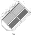
- the battery pack includes a battery box 10, a first battery assembly, a second battery assembly, and a separator 40.
- the first battery assembly includes a plurality of first batteries 20 stacked in a first direction.
- the second battery assembly includes a second battery 30.
- the first battery assembly and the second battery assembly are disposed in the battery box 10 in the first direction.
- the first battery assembly has a first surface 21 facing the second battery assembly, and the second battery assembly has a second surface 31 facing the first battery assembly.
- the separator 40 is located between the second battery assembly and the first battery assembly, and the separator 40 includes a third surface 41 and a fourth surface 42.
- the third surface 41 and the fourth surface 42 respectively face the first surface 21 and the second surface 31.
- An expansion gap is formed between the first surface 21 and the second surface 31, and the expansion gap gradually expands from a second direction, and/or an expansion structure is formed between the third surface 41 and the fourth surface 42, and the expansion structure gradually expands from the second direction.
- the second direction is perpendicular to the first direction, and the second direction extends from a bottom surface of the battery box 10 toward a top surface of the battery box 10.
- the battery pack includes the battery box 10, the first battery assembly, the second battery assembly, and the separator 40.
- the first battery assembly, the second battery assembly, and the separator 40 are disposed in the battery box 10, and the separator 40 is located between the second battery assembly and the first battery assembly.
- the separator 40 may gradually compact the first battery assembly when the separator 40 is installed between the second battery assembly and the first battery assembly. As such, while realizing the clamping of the first battery assembly, the first batteries 20 are prevented from being crushed, thereby improving the usage performance of the battery pack.
- the first battery assembly includes the first batteries 20 stacked in the first direction, that is, the first batteries 20 may be sequentially disposed in the first direction, thereby forming the first battery assembly.
- the second battery assembly may include multiple second batteries 30 stacked in the first direction, that is, the second batteries 30 may be sequentially disposed in the first direction, thereby forming the second battery assembly.
- the first battery assembly and the second battery assembly may be sequentially disposed in the first direction, and the separator 40 is located between the first battery assembly and the second battery assembly, so that the first battery assembly, the separator 40, and the second battery assembly may be sequentially disposed in the first direction.
- two sides of the separator 40 may respectively correspond to one first battery 20 and one second battery 30.
- the second battery assembly may include the second batteries 30 sequentially disposed in a direction perpendicular to the first direction, and at this time, the separator 40 may correspond to end portions of the second batteries 30.
- the first battery assembly has the first surface 21 facing the second battery assembly
- the second battery assembly has the second surface 31 facing the first battery assembly, that is, the separator 40 may be located between the first surface 21 and the second surface 31.
- the separator 40 includes the third surface 41 and the fourth surface 42.
- the third surface 41 and the first surface 21 are disposed opposite to each other, and the fourth surface 42 and the second surface 31 are disposed opposite to each other, so that the separator 40 may be sandwiched between the first surface 21 and the second surface 31.
- the separator 40 may drive the first batteries 20 in the first battery assembly to implement compaction or the separator 40 may also drive the second batteries 30 in the second battery assembly to implement compaction. As such, it is not only convenient for installation, but also can improve the space utilization rate of the battery pack, and also, the first batteries 20 and the second batteries 30 cannot be easily crushed during the process.
- the expansion gap gradually expands from the second direction
- the expansion structure gradually expands from the second direction
- the second direction is perpendicular to the first direction
- the second direction extends from the bottom surface of the battery box 10 to the top surface of the battery box 10.
- the first direction may be parallel to the bottom surface of the battery box 10 and the top surface of the battery box 10.
- the second direction may be perpendicular to the bottom surface of the battery box 10 and the top surface of the battery box 10, and the second direction is directed from the bottom surface of the battery box 10 to the top surface of the battery box 10.
- the battery pack may be placed on a horizontal surface
- the second direction may be a vertical direction and is a direction directed from bottom to top.
- the separator 40 being inserted between the first surface 21 and the second surface 31 may be considered as being inserted between the first surface 21 and the second surface 31 from top to bottom.
- the first battery 20 and the second battery 30 may have same structures, or the first battery 20 and the second battery 30 may have different structures.
- the first battery 20 and the second battery 30 may both be rectangular batteries.
- a battery includes a core and an electrolyte, and is the smallest unit capable of performing electrochemical reactions such as charging/discharging.
- the core refers to a unit formed by winding or laminating a stack portion.
- the stack portion includes a first electrode, a separator, and a second electrode. When the first electrode is a positive electrode, the second electrode is a negative electrode. The polarities of the first electrode and the second electrode may be interchanged.
- the battery is a laminated battery, which is not only convenient for grouping, but can also be processed to obtain a battery with a longer length.
- the core is a laminated core.
- the core has a first pole piece, a second pole piece electrically opposite to the first pole piece, and a diaphragm piece disposed between the first pole piece and the second pole piece that are stacked on each other, so that multiple pairs of first pole pieces and second pole pieces are stacked to form the laminated core.
- the battery may also be a roll core, that is, the first pole piece, the second pole piece electrically opposite to the first pole piece, and the diaphragm piece disposed between the first pole piece and the second pole piece are wound to obtain the roll core.
- each first battery 20 includes two opposite larger surfaces.
- the first direction is perpendicular to the larger surfaces, that is, the adjacent first batteries 20 are stacked through the larger surfaces, which not only facilitates the stacking of the first batteries 20, but also ensures the stability of the stacking of the first batteries 20.
- the adjacent first batteries 20 are stacked through the larger surfaces, and the contact between the larger surfaces enables the first batteries 20 to be evenly stressed during the squeezing process, so as to prevent the first batteries 20 from being structurally damaged due to stress on smaller surfaces of the first batteries 20.
- Each second battery 30 includes two opposite larger surfaces.
- the first direction is perpendicular to the larger surface, that is, the adjacent second batteries 30 are stacked through the larger surfaces.
- the expansion gap is formed between the first surface 21 and the second surface 31, and an equidistant structure is formed between the third surface 41 and the fourth surface 42.
- the separator 40 may be a rectangular structure. During the process of inserting the separator 40 between the first surface 21 and the second surface 31, the first battery assembly and the second battery assembly may be gradually clamped.
- an equidistant gap is formed between the first surface 21 and the second surface 31, and the expansion structure is formed between the third surface 41 and the fourth surface 42.
- a rectangular gap is formed between the first surface 21 and the second surface 31.
- the expansion gap is formed between the first surface 21 and the second surface 31, and the expansion structure is formed between the third surface 41 and the fourth surface 42.
- the expansion gap may be a trapezoidal gap, and the expansion structure is a trapezoidal structure, so that during the process of inserting the separator 40 between the first surface 21 and the second surface 31, the first battery assembly and the second battery assembly may be gradually clamped.
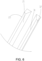
- the first surface 21 is a first inclined surface, and the first inclined surface is inclined relative to the second direction toward a side away from the second surface 31, and/or the second surface 31 is a second inclined surface, and the second inclined surface is inclined relative to the second direction toward a side away from the first surface 21, so that the expansion gap may be formed between the first surface 21 and the second surface 31, and during the process of inserting the separator 40 between the first surface 21 and the second surface 31, the first battery assembly and the second battery assembly may be gradually clamped.
- the second direction may be considered as a vertical direction.
- the first inclined surface is inclined relative to the second direction toward the side away from the second surface 31, that is, the first surface 21 is inclined outward relative to the vertical direction.
- the second inclined surface is inclined relative to the second direction toward the side away from the first surface 21, that is, the second surface 31 is inclined outward relative to the vertical direction.
- the distance between the first surface 21 and the second surface 31 gradually increases from bottom to top, so that during the process of inserting the separator 40 between the first surface 21 and the second surface 31, the distance between the first surface 21 and the second surface 31 gradually increases, such that the first battery assembly and the second battery assembly may be gradually clamped.
- the third surface 41 is a third inclined surface, and the third inclined surface is inclined relative to the second direction toward a side away from the fourth surface 42, and/or the fourth surface 42 is a fourth inclined surface, and the fourth inclined surface is inclined relative to the second direction toward a side away from the third surface 41, so that the expansion structure may be formed between the third surface 41 and the fourth surface 42, and during the process of inserting the separator 40 between the first surface 21 and the second surface 31, the first battery assembly and the second battery assembly may be gradually clamped.
- the second direction may be regarded as a vertical direction.
- the third inclined surface is inclined relative to the second direction toward the side away from the fourth surface 42, that is, the third surface 41 is inclined outward relative to the vertical direction.
- the fourth inclined surface is inclined relative to the second direction toward the side away from the third surface 41, that is, the fourth surface 42 is inclined outward relative to the vertical direction.
- the distance between the third surface 41 and the fourth surface 42 gradually increases from bottom to top, so that during the process of inserting the separator 40 between the first surface 21 and the second surface 31, the distance between the first surface 21 and the second surface 31 gradually increases, such that the first battery assembly and the second battery assembly may be gradually clamped.
- an inclination angle of the first inclined surface relative to the second direction is equal to an inclination angle of the second inclined surface relative to the second direction, that is, the expansion gap formed between the first surface 21 and the second surface 31 is an isosceles trapezoid gap, so that the during the process of inserting the separator 40 between the first surface 21 and the second surface 31, the first battery assembly and the second battery assembly may be gradually clamped.
- an inclination angle of the third inclined surface relative to the second direction is equal to an inclination angle of the fourth inclined surface relative to the second direction, that is, the expansion structure formed between the third surface 41 and the fourth surface 42 may be an isosceles trapezoid structure, so that during the process of inserting the separator 40 between the first surface 21 and the second surface 31, the first battery assembly and the second battery assembly may be gradually clamped.
- an included angle between the first inclined surface and the first direction is 60° to 85°, that is, an included angle between the first inclined surface and the second direction may be 5° to 30°, so as to ensure that during the process of inserting the separator 40 between the first surface 21 and the second surface 31, the first battery assembly and the second battery assembly may be gradually clamped, and a first end plate 22 with the first inclined surface may also be prevented from occupying a larger lateral space.
- the included angle between the first inclined surface and the first direction is 60°, 61°, 62°, 65°, 68°, 70°, 72°, 75°, 78°, 80°, 81°, 82°, 83°, 84°, 85°, etc.
- an included angle between the second inclined surface and the first direction is 60° to 85°, that is, an included angle between the second inclined surface and the second direction may be 5° to 30°, so as to ensure that during the process of inserting the separator 40 between the first surface 21 and the second surface 31, the first battery assembly and the second battery assembly may be gradually clamped, and a second end plate 32 with the second inclined surface may also be prevented from occupying a larger lateral space.
- the included angle between the second inclined surface and the first direction is 60°, 61°, 62°, 65°, 68°, 70°, 72°, 75°, 78°, 80°, 81°, 82°, 83°, 84°, 85°, etc.
- an included angle between the third inclined surface and the first direction is 60° to 85°, that is, an included angle between the third inclined surface and the second direction may be 5° to 30°, so as to ensure that during the process of inserting the separator 40 between the first surface 21 and the second surface 31, the first battery assembly and the second battery assembly may be gradually clamped, and the separator 40 with the third inclined surface may also be prevented from occupying a larger lateral space.
- the included angle between the third inclined surface and the first direction is 60°, 61°, 62°, 65°, 68°, 70°, 72°, 75°, 78°, 80°, 81°, 82°, 83°, 84°, 85°, etc.
- an included angle between the fourth inclined surface and the first direction is 60° to 85°, that is, an included angle between the fourth inclined surface and the second direction may be 5° to 30°, so as to ensure that during the process of inserting the separator 40 between the first surface 21 and the second surface 31, the first battery assembly and the second battery assembly may be gradually clamped, and the separator 40 with the fourth inclined surface may also be prevented from occupying a larger lateral space.
- the included angle between the fourth inclined surface and the first direction is 60°, 61°, 62°, 65°, 68°, 70°, 72°, 75°, 78°, 80°, 81°, 82°, 83°, 84°, 85°, etc.
- At least a part of the expansion gap fits the expansion structure, which not only enables the separator 40 to clamp the first battery assembly and the second battery assembly, but also ensures the connection stability of the separator 40.
- the separator 40 is a beam member, so that when the separator 40 is inserted between the second battery assembly and the first battery assembly from a third direction opposite to the second direction, the separator 40 can drive at least a part of the first battery assembly to move toward a direction away from the second battery assembly, so that the first battery assembly may be clamped, so as to ensure the installation stability of the first battery assembly.
- the second direction may be a vertical direction, and the second direction is a direction directed from bottom to top.
- the third direction is a vertical direction, and the third direction is a direction directed from top to bottom.
- the second battery assembly includes the second batteries 30 stacked in the first direction.
- the separator 40 can drive at least a part of the second battery assembly to move toward a direction away from the first battery assembly, that is, during the process of inserting the separator 40 between the first surface 21 and the second surface 31 from top to bottom, the first battery assembly and the second battery assembly may move toward opposite directions, so that the first battery assembly is clamped and the second battery assembly is clamped.
- the first battery assembly further includes the first end plate 22
- the second battery assembly further includes the second end plate 32
- the first end plate 22 and the second end plate 32 respectively have the first surface 21 and the second surface 31.
- the separator 40 can drive the first end plate 22 and the second end plate 32 to move, so that the first end plate 22 may compact the first batteries 20, and the second end plate 32 compacts the second batteries 30, so that the first battery assembly and the second battery assembly are clamped by the separator 40.
- the first end plate 22 and the second end plate 32 may not only respectively compact the first batteries 20 and the first batteries 20, but also prevents the separator 40 from directly pressing the first batteries 20 and the second batteries 30, so that the first batteries 20 and the second batteries 30 are protected.
- the first end plate 22 includes a first insulating end plate
- the second end plate 32 includes a second insulating end plate, so as to ensure that reliable insulation can be formed between the first batteries 20 and the separator 40, and reliable insulation can be formed between the second batteries 30 and the separator 40.
- the first end plate 22 may be an insulating plate or a part of the first end plate 22 may be an insulating plate, which is not limited herein.
- the first end plate 22 may be provided with an insulating layer.
- the insulating layer may be a coating, such as a coating prepared from a ceramic material such as aluminum oxide (Al 2 O 3 ) and zirconium dioxide (ZrO 2 ).
- the second end plate 32 may be an insulating plate or a part of the second end plate 32 may be an insulating plate, which is not limited herein.
- the second end plate 32 may be provided with an insulating layer.
- the insulating layer may be a coating, such as a coating prepared from a ceramic material such as aluminum oxide (Al 2 O 3 ) and zirconium dioxide (ZrO 2 ).
- the first insulating end plate includes a first elastic structure
- the second insulating end plate includes a second elastic structure.
- the elastic modulus of the first elastic structure is 8000 MPa to 12000 MPa
- the elastic modulus of the second elastic structure is 8000 MPa to 12000 MPa, so that the first end plate 22 and the second end plate 32 may be buffered to prevent the first end plate 22 and the second end plate 32 from deforming the first batteries 20 and the second batteries 30 during the compression process, so as to protect the first batteries 20 and the second batteries 30.
- the elastic modulus of the first elastic structure may be 8000 MPa, 8500 MPa, 9000 MPa, 9500 MPa, 10000 MPa, 11000 MPa, 12000 MPa, etc.
- the elastic modulus of the second elastic structure may be 8000 MPa, 8500 MPa, 9000 MPa, 9500 MPa, 10000 MPa, 11000 MPa, 12000 MPa, etc.
- the separator 40 is connected to the battery box 10, thereby ensuring that the separator 40 can be reliably fixed to the battery box 10, and ensuring that the separator 40 may clamp the first battery assembly and the second battery assembly.
- the separator 40 is detachably connected to the battery box 10, so that the separator 40 may be easily disassembled, so as to facilitate subsequent maintenance of the battery pack.
- the battery box 10 includes a bottom plate 11; and a frame 12, disposed surrounding the bottom plate 11.
- the separator 40 is detachably connected to the bottom plate 11, so that the separator 40 can be disassembled, so as to facilitate subsequent maintenance of the battery pack.
- the frame 12 is connected to the bottom plate 11, and the frame 12 may be disposed on the bottom plate 11 or the frame 12 may be connected to a circumferential edge of the bottom plate 11, which is not limited herein.
- the separator 40 is disposed in the frame 12, thereby separating a large space enclosed by the frame 12, so as to respectively install the first battery assembly and the second battery assembly.
- the battery box 10 may further include a separating beam.
- the separating beam extends in the first direction, so that the separating beam intersects the separator 40, for example, there is one separating beam and one separator 40, so that four independent spaces may be formed in the frame 12, and each independent space may be provided with battery assembly therein.
- One separator 40 may compact four battery assemblies at the same time.
- the battery box 10 may further include a top cover. The top cover is connected to the frame 12, so that the top cover and the bottom plate 11 seal the frame 12.
- the bottom plate 11 may be integrated with a heat exchange channel, or the battery box 10 may further include a heat exchange structure.
- the separator 40 and the bottom plate 11 are connected through a fastener 50, which is not only convenient for connection, but also implements the detachable arrangement between the separator 40 and the bottom plate 11.
- the fasteners 50 may be multiple.
- the fasteners 50 implement the connection between the separator 40 and the bottom plate 11.
- the fasteners 50 may be bolts or the fasteners 50 may be keys.
- the fasteners 50 may be connected to the separator 40 by the bottom plate 11, the fasteners 50 may be connected to the separator 40 by the top cover, or the fasteners 50 may be connected to the top cover, the separator 40, and the bottom plate 11 at the same time.
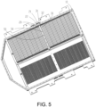
- the separator 40 of the embodiment of the disclosure may be used as a middle crossbeam of the battery box 10. Inclined surfaces are disposed in directions away from the middle crossbeam respectively attached to the first end plate 22 and the second end plate 32.
- the middle crossbeam is separated from the battery box 10. Each battery is stacked from front and rear ends to the middle at the same time.
- a gap between the oppositely disposed first end plate 22 and second end plate 32 is less than a width at a bottom portion of the middle crossbeam.
- the middle crossbeam is installed from top to bottom, and the bottom portion of the middle crossbeam is installed and fixed to the bottom plate 11 or a cold plate through bolts.
- the batteries move to two ends to pre-tighten the batteries.
- the first end plate 22 and the second end plate 32 at end portions are provided with inclined surfaces to prevent the first end plate 22 and the second end plate 32 at the end portions from being offset or structurally deformed due to the action of the pre-tightening force on the batteries.
- An embodiment of the disclosure also provides an assembly method of a battery pack. Please refer to FIG. 7 .
- the assembly method of the battery pack includes the following steps.
- step S101 a first battery assembly and a second battery assembly are placed in a battery box 10 in a first direction.
- the first battery assembly includes multiple first batteries 20 stacked in the first direction
- the second battery assembly includes multiple second batteries 30 stacked in the first direction.
- step S103 a separator 40 is inserted between the first battery assembly and the second battery assembly from top to bottom to drive the first battery assembly and/or the second battery assembly to move.
- the first battery assembly and/or the second battery assembly may be driven to move, which may prevent the first batteries 20 and the second batteries 30 from being crushed while clamping the first battery assembly and the second battery assembly, thereby improving the assembly efficiency of the battery pack.
- the separator 40 when the separator 40 is inserted between the first battery assembly and the second battery assembly from top to bottom, the first battery assembly and the second battery assembly may move in opposite directions, or the first battery assembly moves and the second battery assembly may not move, or the first battery assembly may not move and the second battery assembly moves.
- the assembly method of the battery pack further includes the following step.
- the separator 40 is connected to the battery box 10, thereby ensuring that the separator 40 may be stably connected to the battery box 10, and ensuring that the separator 40 clamps the first battery assembly and the second battery assembly.
- the separator 40 may be connected to the battery box 10 through a fastener 50.
- Multiple fasteners 50 may implement the connection between the separator 40 and a bottom plate 11 of the battery box 10.
- placing the first battery assembly and the second battery assembly in the battery box 10 in the first direction includes the following.
- the first batteries 20 are placed in the battery box 10 in the first direction.
- the second batteries 30 are placed in the battery box 10 in a direction opposite to the first direction. After inserting the separator 40 between the first battery assembly and the second battery assembly from top to bottom, pre-tightening is formed between the first batteries 20 and pre-tightening is formed between the second batteries 30, so that during the process of inserting the separator 40 between the first battery assembly and the second battery assembly, the first battery assembly and the second battery assembly may be gradually clamped, thereby improving the quick assembly of the first battery assembly and the second battery assembly.
- the step of placing the first battery assembly and the second battery assembly in the battery box 10 in the first direction includes the following.
- the first batteries 20 are placed in the battery box 10 in a direction opposite to the first direction
- the second batteries 30 are placed in the battery box 10 in the direction opposite to the first direction.
- the step of placing the first battery assembly and the second battery assembly in the battery box 10 in the first direction includes the following.
- the first batteries 20 are placed in the battery box 10 in a direction opposite to the first direction, and the second batteries 30 are placed in the battery box 10 in the first direction.
- the step of placing the first battery assembly and the second battery assembly in the battery box 10 in the first direction includes the following.
- the first batteries 20 are placed in the battery box 10 in the first direction
- the second batteries 30 are placed in the battery box 10 in the first direction.
- the step of placing the first battery assembly and the second battery assembly in the battery box 10 in the first direction further includes the following.
- a first end plate 22 and a second end plate 32 are placed in the battery box 10, and the first end plate 22 and the second end plate 32 are oppositely disposed, wherein the separator 40 is inserted between the first end plate 22 and the second end plate 32 from top to bottom, such that the first end plate 22 may compact the first batteries 20, and the second end plate 32 compacts the second batteries 30, so as to realize that the first battery assembly and the second battery assembly are clamped by the separator 40.
- the first end plate 22 and the second end plate 32 may not only respectively compact the first batteries 20 and the first batteries 20, but also prevents the separator 40 from directly pressing the first batteries 20 and the second batteries 30, such that the first batteries 20 and the second batteries 30 are protected.
- a minimum distance between the first battery assembly and the second battery assembly is a.
- a length of the first battery assembly is b
- a length of the second battery assembly is c
- a width of a bottom portion of the separator 40 is d
- a compression amount of the first battery assembly is e
- the first batteries 20 and the second batteries 30 can have a reliable expansion space.
- the minimum distance between the first battery assembly and the second battery assembly is less than the width of the bottom portion of the separator 40, so that when the separator 40 is inserted between the first battery assembly and the second battery assembly, the first battery assembly and the second battery assembly may move in opposite directions, so as to implement the compaction of the first battery assembly and the second battery assembly.
- the compression amount e of the first battery assembly may be 0.5%, 0.6%, 0.7%, 0.9%, 1%, 1.5%, 1.6%, 1.7%, 1.9%, 2%, etc.
- the compression amount f of the second battery assembly may be 0.5%, 0.6%, 0.7%, 0.9%, 1%, 1.5%, 1.6%, 1.7%, 1.9%, 2%, etc.
- the assembly method of the battery pack is used to form the abovementioned battery pack.
- the assembly method of the battery pack may adopt related structures of the battery pack, which will not be repeated here.
- An embodiment of the disclosure also provides a disassembly method of a battery pack. Please refer to FIG. 8 , the disassembly method of the battery pack includes the following steps.
- step S201 connection between a separator 40 and a battery box 10 is released.
- step S203 the separator 40 is removed from the battery box 10.
- step S205 at least a part of a first battery assembly on one side of the separator 40 is removed, and/or at least pa art of a second battery assembly on other side of the separator 40 is removed.
- the separator 40 may be removed from the battery box 10 first, so that the first battery assembly and/or the second battery assembly may be removed, which facilitates subsequent maintenance of the first battery assembly and/or the second battery assembly.
- the step of releasing the connection between the separator 40 and the battery box 10 includes releasing connection of a fastener 50 to the separator 40.
- the step of removing the separator 40 from the battery box 10 includes removing the separator 40 from between a first end plate 22 and a second end plate 32, such that a spacing between the first end plate 22 and the second end plate 32 is reduced.
- the disassembly method of the battery pack is used to disassemble the abovementioned battery pack.
Landscapes
- Chemical & Material Sciences (AREA)
- Chemical Kinetics & Catalysis (AREA)
- Electrochemistry (AREA)
- General Chemical & Material Sciences (AREA)
- Battery Mounting, Suspending (AREA)
Applications Claiming Priority (1)
| Application Number | Priority Date | Filing Date | Title |
|---|---|---|---|
| CN202210567058.9A CN114865211A (zh) | 2022-05-23 | 2022-05-23 | 电池包、电池包的组装方法及电池包的拆卸方法 |
Publications (2)
| Publication Number | Publication Date |
|---|---|
| EP4290657A2 true EP4290657A2 (fr) | 2023-12-13 |
| EP4290657A3 EP4290657A3 (fr) | 2024-07-31 |
Family
ID=82639912
Family Applications (1)
| Application Number | Title | Priority Date | Filing Date |
|---|---|---|---|
| EP22196047.9A Pending EP4290657A3 (fr) | 2022-05-23 | 2022-09-16 | Bloc-batterie, procédé d'assemblage de bloc-batterie et procédé de désassemblage de bloc-batterie |
Country Status (3)
| Country | Link |
|---|---|
| US (1) | US20230378589A1 (fr) |
| EP (1) | EP4290657A3 (fr) |
| CN (1) | CN114865211A (fr) |
Families Citing this family (3)
| Publication number | Priority date | Publication date | Assignee | Title |
|---|---|---|---|---|
| CN115832593A (zh) * | 2022-11-09 | 2023-03-21 | 宁德时代新能源科技股份有限公司 | 电池、用电设备及电池的制造方法 |
| CN115995651B (zh) * | 2023-02-21 | 2024-05-17 | 江苏正力新能电池技术有限公司 | 电池包和用电装置 |
| WO2024174876A1 (fr) * | 2023-02-21 | 2024-08-29 | 江苏正力新能电池技术有限公司 | Batterie |
Family Cites Families (4)
| Publication number | Priority date | Publication date | Assignee | Title |
|---|---|---|---|---|
| DE102014221944A1 (de) * | 2014-10-28 | 2016-04-28 | Robert Bosch Gmbh | Spannvorrichtung zum Verspannen von Speichereinheiten eines elektrischen Energiespeichermoduls und entsprechendes Energiespeichermodul |
| WO2019171469A1 (fr) * | 2018-03-06 | 2019-09-12 | 本田技研工業株式会社 | Bloc batterie |
| EP3883007A1 (fr) * | 2020-03-20 | 2021-09-22 | Samsung SDI Co., Ltd. | Module de batterie, procédé d'assemblage d'un module de batterie et véhicule incluant un bloc-batterie comprenant au moins un module de batterie |
| JP7400577B2 (ja) * | 2020-03-23 | 2023-12-19 | トヨタ自動車株式会社 | 組電池の製造方法及び組電池 |
-
2022
- 2022-05-23 CN CN202210567058.9A patent/CN114865211A/zh not_active Withdrawn
- 2022-09-15 US US17/945,994 patent/US20230378589A1/en active Pending
- 2022-09-16 EP EP22196047.9A patent/EP4290657A3/fr active Pending
Also Published As
| Publication number | Publication date |
|---|---|
| EP4290657A3 (fr) | 2024-07-31 |
| US20230378589A1 (en) | 2023-11-23 |
| CN114865211A (zh) | 2022-08-05 |
Similar Documents
| Publication | Publication Date | Title |
|---|---|---|
| EP4290657A2 (fr) | Bloc-batterie, procédé d'assemblage de bloc-batterie et procédé de désassemblage de bloc-batterie | |
| WO2020224370A1 (fr) | Bloc-batterie et véhicule | |
| EP1357624A4 (fr) | Cellule electrochimique a electrolyte polymerique et procede de fonctionnement | |
| US20200295317A1 (en) | Secondary battery, battery module and vehicle | |
| US20230411765A1 (en) | Battery pack, method of assembling battery pack and battery cluster | |
| CN217387341U (zh) | 电池包 | |
| KR100876253B1 (ko) | 폴리머 전지팩 | |
| CN217387340U (zh) | 电池包 | |
| US20230327266A1 (en) | Battery pack and method for disassembling battery pack | |
| CN211643038U (zh) | 软包锂电池电芯夹持式转移机构 | |
| JP2004214123A (ja) | 積層型燃料電池及びその保守方法 | |
| CN114843694A (zh) | 电池包及电池包的组装方法 | |
| US20230378587A1 (en) | Battery pack, method of assembling battery pack and battery cluster | |
| CN217306674U (zh) | 一种电池包及电池簇 | |
| CN217719810U (zh) | 一种电池包及电池簇 | |
| CN217562744U (zh) | 一种电池装置 | |
| CN217334317U (zh) | 一种电池装置 | |
| US20230369732A1 (en) | Battery cell pack and assembly method of battery cell pack | |
| CN218548672U (zh) | 电池包 | |
| CN218039593U (zh) | 电池装置 | |
| CN114927740B (zh) | 一种燃料电池电堆及其压紧装配方法 | |
| CN218548706U (zh) | 电池包 | |
| CN218731521U (zh) | 电池装置 | |
| CN216850163U (zh) | 一种电池组 | |
| CN217788546U (zh) | 一种电池装置 |
Legal Events
| Date | Code | Title | Description |
|---|---|---|---|
| PUAI | Public reference made under article 153(3) epc to a published international application that has entered the european phase |
Free format text: ORIGINAL CODE: 0009012 |
|
| STAA | Information on the status of an ep patent application or granted ep patent |
Free format text: STATUS: REQUEST FOR EXAMINATION WAS MADE |
|
| 17P | Request for examination filed |
Effective date: 20220916 |
|
| AK | Designated contracting states |
Kind code of ref document: A2 Designated state(s): AL AT BE BG CH CY CZ DE DK EE ES FI FR GB GR HR HU IE IS IT LI LT LU LV MC MK MT NL NO PL PT RO RS SE SI SK SM TR |
|
| PUAL | Search report despatched |
Free format text: ORIGINAL CODE: 0009013 |
|
| AK | Designated contracting states |
Kind code of ref document: A3 Designated state(s): AL AT BE BG CH CY CZ DE DK EE ES FI FR GB GR HR HU IE IS IT LI LT LU LV MC MK MT NL NO PL PT RO RS SE SI SK SM TR |
|
| RIC1 | Information provided on ipc code assigned before grant |
Ipc: H01M 50/291 20210101ALI20240625BHEP Ipc: H01M 50/264 20210101ALI20240625BHEP Ipc: H01M 50/244 20210101ALI20240625BHEP Ipc: H01M 50/233 20210101ALI20240625BHEP Ipc: H01M 50/209 20210101AFI20240625BHEP |