EP4290209B1 - Elektrostatischer partikelkollektor - Google Patents
Elektrostatischer partikelkollektor Download PDFInfo
- Publication number
- EP4290209B1 EP4290209B1 EP22178512.4A EP22178512A EP4290209B1 EP 4290209 B1 EP4290209 B1 EP 4290209B1 EP 22178512 A EP22178512 A EP 22178512A EP 4290209 B1 EP4290209 B1 EP 4290209B1
- Authority
- EP
- European Patent Office
- Prior art keywords
- particle
- collector
- inlet
- flow
- esp
- Prior art date
- Legal status (The legal status is an assumption and is not a legal conclusion. Google has not performed a legal analysis and makes no representation as to the accuracy of the status listed.)
- Active
Links
Images







Classifications
-
- G—PHYSICS
- G01—MEASURING; TESTING
- G01N—INVESTIGATING OR ANALYSING MATERIALS BY DETERMINING THEIR CHEMICAL OR PHYSICAL PROPERTIES
- G01N1/00—Sampling; Preparing specimens for investigation
- G01N1/02—Devices for withdrawing samples
- G01N1/22—Devices for withdrawing samples in the gaseous state
- G01N1/2202—Devices for withdrawing samples in the gaseous state involving separation of sample components during sampling
- G01N1/2208—Devices for withdrawing samples in the gaseous state involving separation of sample components during sampling with impactors
-
- B—PERFORMING OPERATIONS; TRANSPORTING
- B03—SEPARATION OF SOLID MATERIALS USING LIQUIDS OR USING PNEUMATIC TABLES OR JIGS; MAGNETIC OR ELECTROSTATIC SEPARATION OF SOLID MATERIALS FROM SOLID MATERIALS OR FLUIDS; SEPARATION BY HIGH-VOLTAGE ELECTRIC FIELDS
- B03C—MAGNETIC OR ELECTROSTATIC SEPARATION OF SOLID MATERIALS FROM SOLID MATERIALS OR FLUIDS; SEPARATION BY HIGH-VOLTAGE ELECTRIC FIELDS
- B03C3/00—Separating dispersed particles from gases or vapour, e.g. air, by electrostatic effect
- B03C3/34—Constructional details or accessories or operation thereof
- B03C3/40—Electrode constructions
- B03C3/45—Collecting-electrodes
- B03C3/49—Collecting-electrodes tubular
-
- B—PERFORMING OPERATIONS; TRANSPORTING
- B03—SEPARATION OF SOLID MATERIALS USING LIQUIDS OR USING PNEUMATIC TABLES OR JIGS; MAGNETIC OR ELECTROSTATIC SEPARATION OF SOLID MATERIALS FROM SOLID MATERIALS OR FLUIDS; SEPARATION BY HIGH-VOLTAGE ELECTRIC FIELDS
- B03C—MAGNETIC OR ELECTROSTATIC SEPARATION OF SOLID MATERIALS FROM SOLID MATERIALS OR FLUIDS; SEPARATION BY HIGH-VOLTAGE ELECTRIC FIELDS
- B03C3/00—Separating dispersed particles from gases or vapour, e.g. air, by electrostatic effect
- B03C3/01—Pretreatment of the gases prior to electrostatic precipitation
- B03C3/011—Prefiltering; Flow controlling
-
- B—PERFORMING OPERATIONS; TRANSPORTING
- B03—SEPARATION OF SOLID MATERIALS USING LIQUIDS OR USING PNEUMATIC TABLES OR JIGS; MAGNETIC OR ELECTROSTATIC SEPARATION OF SOLID MATERIALS FROM SOLID MATERIALS OR FLUIDS; SEPARATION BY HIGH-VOLTAGE ELECTRIC FIELDS
- B03C—MAGNETIC OR ELECTROSTATIC SEPARATION OF SOLID MATERIALS FROM SOLID MATERIALS OR FLUIDS; SEPARATION BY HIGH-VOLTAGE ELECTRIC FIELDS
- B03C3/00—Separating dispersed particles from gases or vapour, e.g. air, by electrostatic effect
- B03C3/017—Combinations of electrostatic separation with other processes, not otherwise provided for
-
- B—PERFORMING OPERATIONS; TRANSPORTING
- B03—SEPARATION OF SOLID MATERIALS USING LIQUIDS OR USING PNEUMATIC TABLES OR JIGS; MAGNETIC OR ELECTROSTATIC SEPARATION OF SOLID MATERIALS FROM SOLID MATERIALS OR FLUIDS; SEPARATION BY HIGH-VOLTAGE ELECTRIC FIELDS
- B03C—MAGNETIC OR ELECTROSTATIC SEPARATION OF SOLID MATERIALS FROM SOLID MATERIALS OR FLUIDS; SEPARATION BY HIGH-VOLTAGE ELECTRIC FIELDS
- B03C3/00—Separating dispersed particles from gases or vapour, e.g. air, by electrostatic effect
- B03C3/02—Plant or installations having external electricity supply
- B03C3/04—Plant or installations having external electricity supply dry type
- B03C3/12—Plant or installations having external electricity supply dry type characterised by separation of ionising and collecting stations
-
- B—PERFORMING OPERATIONS; TRANSPORTING
- B03—SEPARATION OF SOLID MATERIALS USING LIQUIDS OR USING PNEUMATIC TABLES OR JIGS; MAGNETIC OR ELECTROSTATIC SEPARATION OF SOLID MATERIALS FROM SOLID MATERIALS OR FLUIDS; SEPARATION BY HIGH-VOLTAGE ELECTRIC FIELDS
- B03C—MAGNETIC OR ELECTROSTATIC SEPARATION OF SOLID MATERIALS FROM SOLID MATERIALS OR FLUIDS; SEPARATION BY HIGH-VOLTAGE ELECTRIC FIELDS
- B03C3/00—Separating dispersed particles from gases or vapour, e.g. air, by electrostatic effect
- B03C3/34—Constructional details or accessories or operation thereof
- B03C3/36—Controlling flow of gases or vapour
- B03C3/361—Controlling flow of gases or vapour by static mechanical means, e.g. deflector
- B03C3/363—Controlling flow of gases or vapour by static mechanical means, e.g. deflector located before the filter
-
- B—PERFORMING OPERATIONS; TRANSPORTING
- B03—SEPARATION OF SOLID MATERIALS USING LIQUIDS OR USING PNEUMATIC TABLES OR JIGS; MAGNETIC OR ELECTROSTATIC SEPARATION OF SOLID MATERIALS FROM SOLID MATERIALS OR FLUIDS; SEPARATION BY HIGH-VOLTAGE ELECTRIC FIELDS
- B03C—MAGNETIC OR ELECTROSTATIC SEPARATION OF SOLID MATERIALS FROM SOLID MATERIALS OR FLUIDS; SEPARATION BY HIGH-VOLTAGE ELECTRIC FIELDS
- B03C3/00—Separating dispersed particles from gases or vapour, e.g. air, by electrostatic effect
- B03C3/34—Constructional details or accessories or operation thereof
- B03C3/38—Particle charging or ionising stations, e.g. using electric discharge, radioactive radiation or flames
-
- B—PERFORMING OPERATIONS; TRANSPORTING
- B03—SEPARATION OF SOLID MATERIALS USING LIQUIDS OR USING PNEUMATIC TABLES OR JIGS; MAGNETIC OR ELECTROSTATIC SEPARATION OF SOLID MATERIALS FROM SOLID MATERIALS OR FLUIDS; SEPARATION BY HIGH-VOLTAGE ELECTRIC FIELDS
- B03C—MAGNETIC OR ELECTROSTATIC SEPARATION OF SOLID MATERIALS FROM SOLID MATERIALS OR FLUIDS; SEPARATION BY HIGH-VOLTAGE ELECTRIC FIELDS
- B03C3/00—Separating dispersed particles from gases or vapour, e.g. air, by electrostatic effect
- B03C3/34—Constructional details or accessories or operation thereof
- B03C3/40—Electrode constructions
- B03C3/41—Ionising-electrodes
-
- B—PERFORMING OPERATIONS; TRANSPORTING
- B03—SEPARATION OF SOLID MATERIALS USING LIQUIDS OR USING PNEUMATIC TABLES OR JIGS; MAGNETIC OR ELECTROSTATIC SEPARATION OF SOLID MATERIALS FROM SOLID MATERIALS OR FLUIDS; SEPARATION BY HIGH-VOLTAGE ELECTRIC FIELDS
- B03C—MAGNETIC OR ELECTROSTATIC SEPARATION OF SOLID MATERIALS FROM SOLID MATERIALS OR FLUIDS; SEPARATION BY HIGH-VOLTAGE ELECTRIC FIELDS
- B03C3/00—Separating dispersed particles from gases or vapour, e.g. air, by electrostatic effect
- B03C3/34—Constructional details or accessories or operation thereof
- B03C3/40—Electrode constructions
- B03C3/45—Collecting-electrodes
- B03C3/47—Collecting-electrodes flat, e.g. plates, discs, gratings
-
- B—PERFORMING OPERATIONS; TRANSPORTING
- B03—SEPARATION OF SOLID MATERIALS USING LIQUIDS OR USING PNEUMATIC TABLES OR JIGS; MAGNETIC OR ELECTROSTATIC SEPARATION OF SOLID MATERIALS FROM SOLID MATERIALS OR FLUIDS; SEPARATION BY HIGH-VOLTAGE ELECTRIC FIELDS
- B03C—MAGNETIC OR ELECTROSTATIC SEPARATION OF SOLID MATERIALS FROM SOLID MATERIALS OR FLUIDS; SEPARATION BY HIGH-VOLTAGE ELECTRIC FIELDS
- B03C3/00—Separating dispersed particles from gases or vapour, e.g. air, by electrostatic effect
- B03C3/34—Constructional details or accessories or operation thereof
- B03C3/40—Electrode constructions
- B03C3/60—Use of special materials other than liquids
-
- B—PERFORMING OPERATIONS; TRANSPORTING
- B03—SEPARATION OF SOLID MATERIALS USING LIQUIDS OR USING PNEUMATIC TABLES OR JIGS; MAGNETIC OR ELECTROSTATIC SEPARATION OF SOLID MATERIALS FROM SOLID MATERIALS OR FLUIDS; SEPARATION BY HIGH-VOLTAGE ELECTRIC FIELDS
- B03C—MAGNETIC OR ELECTROSTATIC SEPARATION OF SOLID MATERIALS FROM SOLID MATERIALS OR FLUIDS; SEPARATION BY HIGH-VOLTAGE ELECTRIC FIELDS
- B03C3/00—Separating dispersed particles from gases or vapour, e.g. air, by electrostatic effect
- B03C3/34—Constructional details or accessories or operation thereof
- B03C3/66—Applications of electricity supply techniques
- B03C3/68—Control systems therefor
-
- B—PERFORMING OPERATIONS; TRANSPORTING
- B03—SEPARATION OF SOLID MATERIALS USING LIQUIDS OR USING PNEUMATIC TABLES OR JIGS; MAGNETIC OR ELECTROSTATIC SEPARATION OF SOLID MATERIALS FROM SOLID MATERIALS OR FLUIDS; SEPARATION BY HIGH-VOLTAGE ELECTRIC FIELDS
- B03C—MAGNETIC OR ELECTROSTATIC SEPARATION OF SOLID MATERIALS FROM SOLID MATERIALS OR FLUIDS; SEPARATION BY HIGH-VOLTAGE ELECTRIC FIELDS
- B03C3/00—Separating dispersed particles from gases or vapour, e.g. air, by electrostatic effect
- B03C3/34—Constructional details or accessories or operation thereof
- B03C3/74—Cleaning the electrodes
- B03C3/80—Cleaning the electrodes by gas or solid particle blasting
-
- G—PHYSICS
- G01—MEASURING; TESTING
- G01N—INVESTIGATING OR ANALYSING MATERIALS BY DETERMINING THEIR CHEMICAL OR PHYSICAL PROPERTIES
- G01N1/00—Sampling; Preparing specimens for investigation
- G01N1/02—Devices for withdrawing samples
- G01N1/22—Devices for withdrawing samples in the gaseous state
- G01N1/2247—Sampling from a flowing stream of gas
-
- G—PHYSICS
- G01—MEASURING; TESTING
- G01N—INVESTIGATING OR ANALYSING MATERIALS BY DETERMINING THEIR CHEMICAL OR PHYSICAL PROPERTIES
- G01N1/00—Sampling; Preparing specimens for investigation
- G01N1/28—Preparing specimens for investigation including physical details of (bio-)chemical methods covered elsewhere, e.g. G01N33/50, C12Q
- G01N1/40—Concentrating samples
-
- G—PHYSICS
- G01—MEASURING; TESTING
- G01N—INVESTIGATING OR ANALYSING MATERIALS BY DETERMINING THEIR CHEMICAL OR PHYSICAL PROPERTIES
- G01N15/00—Investigating characteristics of particles; Investigating permeability, pore-volume or surface-area of porous materials
- G01N15/02—Investigating particle size or size distribution
- G01N15/0266—Investigating particle size or size distribution with electrical classification
-
- G—PHYSICS
- G01—MEASURING; TESTING
- G01N—INVESTIGATING OR ANALYSING MATERIALS BY DETERMINING THEIR CHEMICAL OR PHYSICAL PROPERTIES
- G01N15/00—Investigating characteristics of particles; Investigating permeability, pore-volume or surface-area of porous materials
- G01N15/06—Investigating concentration of particle suspensions
- G01N15/0606—Investigating concentration of particle suspensions by collecting particles on a support
- G01N15/0612—Optical scan of the deposits
-
- B—PERFORMING OPERATIONS; TRANSPORTING
- B03—SEPARATION OF SOLID MATERIALS USING LIQUIDS OR USING PNEUMATIC TABLES OR JIGS; MAGNETIC OR ELECTROSTATIC SEPARATION OF SOLID MATERIALS FROM SOLID MATERIALS OR FLUIDS; SEPARATION BY HIGH-VOLTAGE ELECTRIC FIELDS
- B03C—MAGNETIC OR ELECTROSTATIC SEPARATION OF SOLID MATERIALS FROM SOLID MATERIALS OR FLUIDS; SEPARATION BY HIGH-VOLTAGE ELECTRIC FIELDS
- B03C2201/00—Details of magnetic or electrostatic separation
- B03C2201/04—Ionising electrode being a wire
-
- B—PERFORMING OPERATIONS; TRANSPORTING
- B03—SEPARATION OF SOLID MATERIALS USING LIQUIDS OR USING PNEUMATIC TABLES OR JIGS; MAGNETIC OR ELECTROSTATIC SEPARATION OF SOLID MATERIALS FROM SOLID MATERIALS OR FLUIDS; SEPARATION BY HIGH-VOLTAGE ELECTRIC FIELDS
- B03C—MAGNETIC OR ELECTROSTATIC SEPARATION OF SOLID MATERIALS FROM SOLID MATERIALS OR FLUIDS; SEPARATION BY HIGH-VOLTAGE ELECTRIC FIELDS
- B03C2201/00—Details of magnetic or electrostatic separation
- B03C2201/24—Details of magnetic or electrostatic separation for measuring or calculating of parameters, e.g. efficiency
-
- B—PERFORMING OPERATIONS; TRANSPORTING
- B03—SEPARATION OF SOLID MATERIALS USING LIQUIDS OR USING PNEUMATIC TABLES OR JIGS; MAGNETIC OR ELECTROSTATIC SEPARATION OF SOLID MATERIALS FROM SOLID MATERIALS OR FLUIDS; SEPARATION BY HIGH-VOLTAGE ELECTRIC FIELDS
- B03C—MAGNETIC OR ELECTROSTATIC SEPARATION OF SOLID MATERIALS FROM SOLID MATERIALS OR FLUIDS; SEPARATION BY HIGH-VOLTAGE ELECTRIC FIELDS
- B03C2201/00—Details of magnetic or electrostatic separation
- B03C2201/28—Parts being designed to be removed for cleaning purposes
-
- B—PERFORMING OPERATIONS; TRANSPORTING
- B03—SEPARATION OF SOLID MATERIALS USING LIQUIDS OR USING PNEUMATIC TABLES OR JIGS; MAGNETIC OR ELECTROSTATIC SEPARATION OF SOLID MATERIALS FROM SOLID MATERIALS OR FLUIDS; SEPARATION BY HIGH-VOLTAGE ELECTRIC FIELDS
- B03C—MAGNETIC OR ELECTROSTATIC SEPARATION OF SOLID MATERIALS FROM SOLID MATERIALS OR FLUIDS; SEPARATION BY HIGH-VOLTAGE ELECTRIC FIELDS
- B03C2201/00—Details of magnetic or electrostatic separation
- B03C2201/32—Checking the quality of the result or the well-functioning of the device
-
- G—PHYSICS
- G01—MEASURING; TESTING
- G01N—INVESTIGATING OR ANALYSING MATERIALS BY DETERMINING THEIR CHEMICAL OR PHYSICAL PROPERTIES
- G01N1/00—Sampling; Preparing specimens for investigation
- G01N1/02—Devices for withdrawing samples
- G01N1/22—Devices for withdrawing samples in the gaseous state
- G01N1/2202—Devices for withdrawing samples in the gaseous state involving separation of sample components during sampling
- G01N2001/222—Other features
- G01N2001/2223—Other features aerosol sampling devices
-
- G—PHYSICS
- G01—MEASURING; TESTING
- G01N—INVESTIGATING OR ANALYSING MATERIALS BY DETERMINING THEIR CHEMICAL OR PHYSICAL PROPERTIES
- G01N1/00—Sampling; Preparing specimens for investigation
- G01N1/28—Preparing specimens for investigation including physical details of (bio-)chemical methods covered elsewhere, e.g. G01N33/50, C12Q
- G01N1/40—Concentrating samples
- G01N2001/4038—Concentrating samples electric methods, e.g. electromigration, electrophoresis, ionisation
-
- G—PHYSICS
- G01—MEASURING; TESTING
- G01N—INVESTIGATING OR ANALYSING MATERIALS BY DETERMINING THEIR CHEMICAL OR PHYSICAL PROPERTIES
- G01N15/00—Investigating characteristics of particles; Investigating permeability, pore-volume or surface-area of porous materials
- G01N2015/0042—Investigating dispersion of solids
- G01N2015/0046—Investigating dispersion of solids in gas, e.g. smoke
-
- G—PHYSICS
- G01—MEASURING; TESTING
- G01N—INVESTIGATING OR ANALYSING MATERIALS BY DETERMINING THEIR CHEMICAL OR PHYSICAL PROPERTIES
- G01N21/00—Investigating or analysing materials by the use of optical means, i.e. using sub-millimetre waves, infrared, visible or ultraviolet light
- G01N21/01—Arrangements or apparatus for facilitating the optical investigation
- G01N21/15—Preventing contamination of the components of the optical system or obstruction of the light path
- G01N2021/151—Gas blown
Definitions
- This invention relates to an electrostatic particle collector, for collecting particles carried in a gas, for instance airborne particles.
- the invention relates in particular to a particle collector for obtaining samples of particles carried in a gaseous environment, for instance for measuring or characterizing particles that may represent contaminants, pollen, pollutants and other substances in air or in other gaseous environments.
- ESP electrostatic precipitators
- linear ESP linear ESP
- radial ESP generally orthogonal to the collection surface
- Sampling applications may include sample collections for spectroscopy and spectrometry or other types of chemical analyses for studies in air quality, atmospheric science, or industries that involve generation of particles such as in manufacturing industries, construction and e-cigarettes where customer safety is a consideration.
- the aforementioned advantageous properties of ESP's would also be useful in seeding applications for subsequent epitaxial film growth of crystals that can prove useful in membrane technology and nanocrystal technology.
- Further applications that use particle collection with ESP systems may include biological samples needed for optical analysis or other in vitro studies. ESP particle collection may also be used in certain coating applications.
- An orthogonal electrostatic particle collection device comprising sheath flow is known from US8044350B2 , however the particles precipitated on the electrode in the disc precipitator portion are not observed, rather it is the particles that pass through the precipitator that are counted.
- the particle size distribution may be obtained by stepping the precipitation voltage through the entire voltage range and measuring the electrical charges associated with penetrating particles.
- the purpose of the precipitator is thus to act as a cut-off "filter” that retains particles above a certain size and allow particles below said threshold to pass through, such cut-off threshold being dependent inter alia on the voltage applied across the electrodes which can be varied in order to perform a full analysis of the particles in the gas flow.
- the distribution of particles on the electrode in the disc precipitator is unimportant and the problem of having a uniform distribution which is not particle size dependent is not considered.
- an object of the invention is to provide an electrostatic particle collector apparatus for automated optical analysis of the collected particles that has a high spatial uniformity in the deposition pattern with low size dependence of the particles and low chemical interference.
- an ESP particle collector for collecting particles in a particle containing gas stream, comprising an inlet section, a collector section, and an electrode arrangement, the inlet section comprising a flow tube defining a gas flow channel therein bounded by a guide wall extending between an entry end and a collector end that serves as an inlet to the collector section, the entry end comprising an inlet for the particle gas stream and a sheath flow inlet portion for generating a sheath flow around the particle gas stream, the collector section comprising a housing coupled to the flow tube, and a collector plate mounted therein having a particle collection surface.
- the ESP particle collector comprises an optical measuring instrument configured to transmit light through the collector plate along a centre axis A orthogonal or substantially orthogonal to the particle collection surface for optical analysis of the collector plate particle collection surface to measure particles collected thereon, and wherein the flow tube has a bent portion such that the entry end is positioned out of the centre axis A to allow the light to be transmitted through the collector plate in the direction of the centre axis and to be picked up without interfering with the gas flow or the gas inlet.
- the flow tube comprises a first portion arranged along an initial inclined axis ( Gi ) connected via the bent portion to a second portion arranged along the centre axis ( A ) connected to the collector section 6, an angle of inclination ( ⁇ ) of the initial axis ( Gi ) relative to the centre axis ( A ) being less than 60°, preferably less than 40°, more preferably less than 30°, for instance in range of 10° to 25°.
- a length ( d2 ) of the second portion of flow tube is in a range of 0.3D to 0.7D, D being an overall length of the flow tube.
- the optical measuring instrument comprises a spectroscopic optical instrument comprising a light source arranged to project light through the collector plate and a light detector arranged to capture the light transmitted through the collector plate from the light source.
- the ESP particle collector further comprises a cleaning system comprising one or more nozzles arranged to direct one or more jets of a cleaning gas on the collector plate particle collection surface.
- the collector plate is mounted on a motorized movable platform to move the collector plate away from the measurement position for the cleaning operation.
- the ESP particle collector further comprises a purge gas source connected fluidically via a valve to the gas inlet, for instance the sheath gas flow inlet, configured to purge the inlet section and collector section gas flow channels prior to the measurement cycle.
- a purge gas source connected fluidically via a valve to the gas inlet, for instance the sheath gas flow inlet, configured to purge the inlet section and collector section gas flow channels prior to the measurement cycle.
- the ESP particle collector further comprises a controller connected to various devices of the ESP particle collector allowing the automated measurement of collected particles, said devices including some or all of: the particle charger; gas pumps as for the particle gas flow, for the sheath gas flow, for the outlet; a purge gas valve, a motorized platform for moving the collector plate; a cleaning system; and the optical measuring instrument.
- the ESP particle collector in a variant, comprises a pair of devices each having said inlet and collector sections and associated flow tubes, coupled optically to a common said measuring instrument.
- the electrode arrangement comprises at least a base electrode positioned below the collection surface and a counter-base electrode positioned at a separation distance L2 above the collection surface such that an electrical field is generated between the electrodes configured to precipitate said particles on the collection surface, wherein the electric field is in a range of 0.1 kV per mm to 1.5 kV per mm, with an absolute voltage on any said electrode that is less than 10 kV, and wherein a ratio ratio_1 of a radius L1 of said inlet at the collector end divided by said separation distance L2 is in a range of 0.8 to 1.2.
- the base electrode preferably has an annular shape that permits the optical beam to pass through the centre.
- the collector plate is mounted on a collector plate holder, removably mounted in the housing to allow the collector plate to be optically analysed by an external instrument for measurement of particles collected thereon.
- the ESP particle collector further comprises a particle measurement instrument arranged in the housing above or below the particle collection surface to measure the particles collected on the particle collection surface.
- a ratio_2 (L1 / L4) of the radius L1 of said inlet divided by a radius L4 of the base electrode is less than 1.
- said ratio_2 (L1 / L4) is less than 0.7, for instance 0.5 or lower.
- a ratio lim s (Ls / L1) of an inner radius Ls of the said sheath flow relative to the inlet radius L1 is less than 0.6.
- said ratio lim s (Ls / LL) is in a range of 0.2 to 0.5.
- a ratio ratio_3 of the radius L1 of said inlet divided by a radius L3 of the collector plate (L1 / L3) is in a range of 0.05 to 20.
- said ratio ratio_3 ( L1 / L3 ) is in a range of 0.1 to 5.
- the electrode arrangement further comprises a tube electrode around the collector end forming the inlet to the collector section.
- the sheath flow inlet portion comprises a sheath flow gas inlet, a gas chamber and an annular sheath flow gas outlet surrounding the centre of the flow channel and configured to generate an annular sheath flow along the guide wall of the flow channel surrounding the particle gas stream.
- the ESP particle collector further comprises a particle charger arranged upstream of the inlet section configured to electrically charge the particles of the gas stream entering the inlet section.
- the particle charger is configured to impart a charge on the particles contained in the gas stream in a range of about 1 elementary charge per 10nm diameter to about 1 elementary charge per 30nm diameter of a particle.
- the collector plate is made of a transparent conductive or semiconductor material.
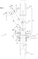
- an ESP particle collector 1 comprises an inlet section 4, a collector section 6 including a collector plate 20, an electrode arrangement 8, and an optical measuring instrument 9 for automated measurement of the particles collected on the collector plate.
- the particle collector may further comprise a particle charger 2 arranged upstream of the inlet section 4 configured to electrically charge the particles of the gas stream entering the inlet section 4.
- the charge is in a range of 1 elementary charge per 10nm diameter to about one elementary charge per 40nm diameter for instance around 1 elementary charge per 20nm diameter.
- the relatively small charge allows the particles to be charged with a low generation of reactive species such as ions and radicals such as ozone, in order to ensure low chemical interference on the particles contained in the gas stream.
- Various per se known particle chargers may be used, such known chargers using field charging, diffusion charging, or ultraviolet charging, provided that they have a low reactive species generation on the particles in the gas stream.
- An example of a charger that may be used for the invention is for instance described in Han [5] which describes a wire-wire charger with a low ozone production.
- the charging of the particle stream advantageously assists in improving uniforms spatial distribution of particles on the collector plate.
- the optical measuring instrument 9 is configured to transmit light through the collector plate along an axis A orthogonal or substantially orthogonal to a particle collection surface 23 on the collector plate.
- the optical measuring instrument 9, in a preferred embodiment, comprises a spectroscopic optical instrument comprising a light source 11 arranged to project light through the collector plate 20 and a light detector 13 arranged to capture the light transmitted through the collector plate 20 from the light source.
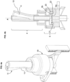
- the inlet section 4 comprises a flow tube 10 defining a gas flow channel 12 therein bounded by a guide wall 24 that is preferably of a generally axisymmetric shape at the collector end section.
- the flow tube at the collector end section may be generally cylindrical as illustrated in embodiment of figure 1a or may have other axisymmetric shapes for instance as illustrated in figures 1b and 1c .
- the flow tube may however also have non-axisymmetric cross-sectional profiles such as polygonal (square, pentagon, hexagon or other polygons).
- the flow tube 10 extends between an entry end 14 and a collector end 16 that serves as a gas inlet to the collector section 6.
- the flow tube has bent portion 15 such that the entry end 14 is positioned out of the centre axis A to allow the light to be transmitted through the collector plate in the direction of the centre axis and to be picked up without interfering with the gas flow or the gas inlet.
- the gas thus flows in a first portion along an initial inclined axis Gi before joining a second portion along the centre axis A and then entering the collector section 6.
- the angle of inclination ⁇ of the initial axis Gi relative to the centre axis A is less than 60°, preferably less than 40°, more preferably less than 30°, for instance between 10°and 25°
- the length d2 of the second portion of flow tube is preferably in a range of 0.3D to 0.7D, D being the overall length of the flow tube, in order to ensure a substantially axisymmetrical developed flow of the gas particles and sheath at the collector section 6.
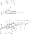
- the bent portion 15 is preferably curved as illustrated in figure 3a and 3b to reduce turbulence and ensure that the gas flow is substantially laminar while maintaining a similar distribution of the streamlines about the centre line.
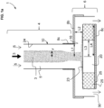
- the entry end 14 comprises an inlet 28 for the particle gas stream and a sheath flow inlet portion 26 for generating a sheath flow around the particle gas stream.
- particle gas stream it is meant the gas stream containing the particles to be collected in the collector section 6.
- the sheath flow inlet portion 26 comprises a sheath flow gas inlet 27, a gas chamber 29 and a sheath flow gas outlet 31 surrounding the centre of the flow channel 12 and configured to generate and annular sheath flow along the wall 24 of the flow channel 12 surrounding the particle gas flow.
- the chamber 29 serves to contain a volume of gas with a low or essentially no pressure gradient within the chamber with respect to the sheath gas inlet, such that the radial nozzle defining the sheath flow outlet 31 generates an even circumferential sheath flow.
- the flow rates of the sheath flow and particle gas flow may be calibrated such that the two gas streams have laminar flow properties and the boundary layer between the sheath flow stream and particle gas stream remains laminar substantially without mixing.
- the gas flow streams are configured such that the Reynolds number is below 2200, preferably below 500, for instance around 200.
- the flow tube 10 has an overall length D that is configured to ensure that the velocity of the sheath gas stream and particle gas stream at the interface therebetween accelerates such that the velocity profile of the gas stream within the flow channel collector end is a substantially continuous single rounded profile with a substantially flatter profile compared to the gas stream as the entry end.
- the laminar flow profile is substantially parabolic and joins the particle gas stream at the boundary interface with a velocity close to zero that accelerates as the gas stream flows away from the sheath flow outlet.
- the sheath flow separating the particle gas flow from the guide wall 24 reduces or avoids deposition of particles on the guide wall 24 and has further advantages in improving spatial uniformity of the particle deposition in the collector section 6, reducing also chemical interference, reducing size dependence in the collection and improving collection efficiency. This is not only because it reduces the gradient in axial velocity of the particle gas stream that flows on to the collector plate, but also due to the separation of the gas stream from the flow channel walls, it reduces interference of the charge particles with the flow channels walls.
- the collector section 6 comprises a housing 18 coupled to the flow tube 10, and the collector plate 20 mounted therein on a collector plate holder 22.
- the collector plate comprises a transparent disc, for instance made of a crystal such as a Silicon, Zinc Selenide, or Germanium crystal, for optical analysis using for instance infrared spectroscopy.
- the collector disc may be removably mounted within the housing for cleaning, replacement, or for placement in an external measurement instrument for analysing the particles deposited on the collector plate 20 as a complementary measurement to the internal measurement.
- the collector plate 20 may comprise a filler material 21 arranged around the collector plate 20. The gas stream flow over the collector plate is thus defined not only by the collector end 16 of the flow tube 10 but also the radius of the collector plate 20 and the filler material 21 therearound.
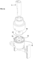
- the ESP particle collector 1 may advantageously comprise a cleaning system 7 comprising one or more nozzles 17 arranged to direct one or more jets of a cleaning fluid on the collector plate particle collection surface 23 of the collector plate to blow away particles on the collection surface.
- the collector plate may be mounted on a motorized movable holder or platform 19 to lower the housing 18 and the collector plate 20 away from the counter-base electrode 8b for the cleaning operation.
- the cleaning system may be operated at the end of a measurement cycle, or at defined intervals. The lowering of the housing 18 using motorized movable holder or platform 19 can further allow for insertion or removal of collector plate 20 or collector plate holder 22.
- the cleaning fluid may for instance be liquid/ gas mixture of CO 2 with suspended solids, or other preferably inert gases such as argon or nitrogen.
- the cleaning fluid may be supplied from a dedicated cleaning fluid source, or may be supplied from a filtered purge gas that would improve the portability of the system.
- the ESP particle collector 1 may further comprise a purge gas source 47 connected fluidically via a valve 49 to the gas inlet, for instance the sheath gas flow inlet, to purge the inlet section and collector section gas flow channels prior to a new particle collection cycle.
- the purge gas source may be operated at the beginning of a measurement cycle, or at defined intervals, and may be operated prior to or simultaneously with the cleaning system.
- the purge gas may for instance be argon or nitrogen, or other inert gases that do not interfere with mid-IR wavelengths.
- the purge gas may also be dry air supplied from a purge-gas generator, which comprises self-regenerating columns of molecular sieves that only require pressurized air and electricity. This allows to remove the need for supplying and replacing gas cylinders.
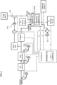
- the controller 41 is connected to the various automated devices of the ESP particle collector allowing the automated measurement of collected particles.
- the controller may be for instance be connected to all or some of the following components of the ESP particle collector: the particle charger 2, various gas pumps 51a, 51b, 51c such as for the particle gas flow, for the sheath gas flow, for the outlet, the purge gas valve 47, the motorized platform 19, the cleaning system 7, and the measuring instrument 9.
- the ESP particle collector may further include a graphical user interface including a display 45 for inputting data or commands and for displaying measurement results and control information.
- the electrode arrangement 8 comprises at least a base electrode 8a positioned adjacent or on an underside 25 of the collector plate 20, below the collection surface 23 where particles are deposited.
- the base electrode may have a central orifice to allow the light of the measurement instrument to pass through the collector plate.
- the electrode arrangement 8 further comprises a counter-base electrode 8b positioned at a certain separation distance L2 above the collector plate 20 and which may be arranged substantially parallel to the base electrode 8a such that an electrical field is generated between the electrodes 8a, 8b.
- the electrode arrangement may optionally further comprise a tube electrode 8c around the collector end 16 forming the inlet to the collector section 6.
- the tube electrode 8c may be at the same voltage as the counter-base electrode 8b or at a different voltage therefrom separated by an insulating element from the counter-base electrode 8b.
- the various electrodes may be at a certain voltage with respect to ground or one of the electrodes may be connected to ground and the other at a potential different from ground.
- the inlet channel at the collector end has a radius defined as L1.
- the collector plate has a radius defined as L3.
- the base electrode has a radius defined as L4.
- the distance between the counter-base electrode 8a and the collector plate 20 has a separation distance defined as L2.
- An optimal ratio_1 (L1 / L2) affects the variation in the electric field under the inlet tube which may be optimized to improve spatial uniformity and collection efficiency.
- a lower bound value for an optimal ratio_3 may be constrained by any value where impaction affects the final deposition pattern, however collection mass flux is generally higher if this ratio is more than 1.
- An upper bound value may be constrained by a fixed limit on operating voltage (and maximum electric field strength) and on ratio 1 above, for example by, rati o 3 ⁇ V max E max ⁇ rati o 1 collection disc radius
- the upper bound value may also be constrained by a desired efficiency, for example by, ratio 3 ⁇ 1 efficiency ⁇ radial sheath position lim _ s .
- ratio_2 another ratio L1/L4 of interest for high spatial uniformity and low chemical interference is a ratio between the radius L1 of the inlet channel collector end and the base electrode radius L4, named hereinafter by convention as ratio_2.
- the ratio_2 controls the electric field concentration effects on the collector plate's edges.
- An optimal ratio_2 may thus serve to improve spatial uniformity and lowers the electric field strengths in some regions, in particular to lower the variation in electric field strength under the inlet tube.
- the ratio_1 (L1 divided by L2) is in a range of 0.3 to 1.8, preferably in a range of 0.8 to 1.2.
- the ratio_2 (L1/L4) is less than 1, preferably less than 0.7, for instance 0,5 or lower.
- the ratio_3 (L1 divided by L3) is preferably in a range of 0.05 to 20, preferably in a range of 0.1 to 5.
- the electric field generated between the base electrode 8a and counter-base electrode 8b is preferably in a range of 0.1 kV per mm to 3 kV per mm, preferably from 0.5 kV per mm to 1,5 kV per mm for instance around 1kV per mm, with an absolute voltage on any electrode that is less than 10 kV, to reduce chemical interference while ensuring high collection efficiency.
- Ratio lim s is in a range of 0.1 to 0.9, preferably in a range of 0.1 to 0.6, for instance around 0.4, to ensure a sheath flow layer sufficient to provide a good separation between the gas particle stream and the flow channel wall 24 as well as ensuring that the particle gas stream impinging upon the collector plate 20 allows optimal uniform spatial distribution of the particles on the collector plate.
- Sheath flow This is an artificial method of tuning this ratio described above, as even for a larger tube, a sheath flow limits the incoming particles to a certain radial distance.
- Low Chemical interference Defining the geometric length ratios Define separation distance L2 required to maintain a low electric field strength, and keep deposited particles further away from high-voltage counter-base electrode 8b. Moreover, increasing the ratio of inlet radius L1 to the base electrode 8a radius L4 is useful for reducing local electric field strengths. Sheath flow: This keeps particle laden air streams farther away from the high-voltage counter-base electrode 8b in the collection region.
- Embodiments of the invention may advantageously be used in various applications, including:
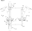
- the ESP particle collector 1 may have a pair of inlet and collector sections 4, 6 and associated flow tubes, coupled optically to a common measuring instrument 9.
- the pair of inlet and collector sections are arranged in mirror image symmetry.
- the pair of inlet and collector sections are arranged in parallel, with beam splitters and mirrors 53 positioned in the optical path between the light source 11 and light detector 13 so as to split the beam at the source 11 into two beams, one passing through each collector plate 20, and then collect the two beams at the detector 13.
- the pair of devices 1a, 1b, coupled to a common measuring instrument 9 allows to double the number of particles measured and thus increase the sensitivity and/or reduce the measurement cycle time of the measurement.
- the pair of devices allows to collect gases for measurement from two different positions, for instance in order to provide an average measurement value of a certain volume of measurement or to reduce the impact on measurement results due to a localized pollution at the inlet of one of the devices.
- Aerosol, or particulate matter is difficult to characterize because of its wide range of particle sizes (few nanometers to several micrometers); constituents (various organic and inorganic compounds); concentration (one to hundreds of ⁇ g / m 3 , for PM ⁇ 2.5 ⁇ m ); morphology; state (liquid or solid); and time-dependent modification.
- An ideal collector would enable collecting an aerosol sample that is an identical copy of the aerosol in air at an instant of time. Such a collector, when used with an ideal characterization method, will allow an ideal quantitative measurement of the composition of the aerosol.
- most conventional particle collectors modify or preferentially sample certain size ranges, chemical composition, morphology or state.
- collected sample is characterized for the constituents and/or their composition using numerous spectrometric techniques, which can induce further modifications. For example, most spectroscopic techniques require collecting aerosol on a surface for a prolonged period to make a confident claim about its constituents, composition.
- Infrared (IR) spectroscopy is a non-destructive method, which provides useful chemical information about the constituents.
- Current methods for collecting samples use filters that are made of material which interferes with the IR spectra and thus lowers detection capabilities. Hence, collection on an IR-transparent substrate (for example, chalcogenide crystals) is desirable.
- a particle collector according to embodiments of the invention that achieves the advantages mentioned above allows to make a good quantitative measurement using IR-spectroscopy.
- “Low size-dependence”, “Low chemical interference” and “High collection efficiency” is required to collect an aerosol sample that is identical to the aerosol in air
- “High spatial uniformity in deposition pattern” is required to reduce optical artefacts or spectrometer dependence
- “High collection mass flux” is required to reduce the collection time needed for making a confident claim.
- Electrostatic precipitation is a versatile method of collection and does not suffer from high pressure drop (which can modify the aerosol chemical composition, for example in filtration), or from bounce-off effects (which preferentially samples the size range and liquids, for example in impaction).
- ESP is a common device for dust removal but is also used for particle deposition.
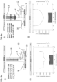
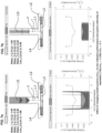
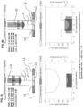
- Example 2 This example shown in Figure 5b , has the same collection plate radius and differs from Example 1 above mainly in the ratio 3 value L1/L3.
- Dielectric around counter-base and tube electrodes • Low conductivity: This would act as an insulation around the electrodes. • High relative permittivity: This would not dampen the electric field strength. High-k dielectrics are preferable. Very thin layer of lowk dielectric would also find application.
Landscapes
- Health & Medical Sciences (AREA)
- Chemical & Material Sciences (AREA)
- Life Sciences & Earth Sciences (AREA)
- General Physics & Mathematics (AREA)
- Physics & Mathematics (AREA)
- Analytical Chemistry (AREA)
- Biochemistry (AREA)
- General Health & Medical Sciences (AREA)
- Immunology (AREA)
- Pathology (AREA)
- Engineering & Computer Science (AREA)
- Dispersion Chemistry (AREA)
- Biomedical Technology (AREA)
- Molecular Biology (AREA)
- Automation & Control Theory (AREA)
- Sampling And Sample Adjustment (AREA)
Claims (15)
- Elektrostatischer Partikelabscheider (ESP) (1) zum Abscheiden von Partikeln in einer partikelhaltigen Gasströmung, der eine Einlasssektion (4), eine Abscheidersektion (6) und eine Elektrodenanordnung (8) umfasst, wobei die Einlasssektion ein Strömungsrohr (10) umfasst, das darin einen Gasströmungskanal (12) definiert, der durch eine Führungswand (24) begrenzt ist, die sich zwischen einem Eintrittsende (14) und einem Abscheiderende (16) erstreckt, das als ein Einlass zur Abscheidersektion (6) dient, wobei das Eintrittsende einen Einlass (28) für die Partikelgasströmung umfasst, die Abscheidersektion ein Gehäuse (18), das an das Strömungsrohr gekoppelt ist, und eine darin montierte Abscheiderplatte (20) umfasst, die eine Partikelabscheidungsoberfläche (23) umfasst, wobei der elektrostatische Partikelabscheider (ESP) ein optisches Messinstrument (9) umfasst, das dazu ausgestaltet ist, Licht durch die Abscheiderplatte entlang einer Mittelachse (A) orthogonal oder im Wesentlichen orthogonal zur Partikelabscheidungsoberfläche zur optischen Analyse der Partikelabscheidungsoberfläche der Abscheiderplatte durchzulassen, um darauf abgeschiedene Partikel zu messen, wobei der elektrostatische Partikelabscheider (ESP) dadurch gekennzeichnet ist, dass das Eintrittsende einen Mantelströmungs-Einlassabschnitt (26) zum Erzeugen einer Mantelströmung um die Partikelgasströmung umfasst, und dadurch, dass das Strömungsrohr einen gekrümmten Abschnitt (15) umfasst, derart dass das Eintrittsende (14) außerhalb der Mittelachse A positioniert ist, um das Durchlässen des Lichts durch die Abscheiderplatte in der Richtung der Mittelachse und sein Aufnehmen ohne gegenseitige Beeinflussung mit der Gasströmung oder dem Gaseinlass zu erlauben, wobei das Strömungsrohr einen ersten Abschnitt umfasst, der entlang einer geneigten Ausgangsachse (Gi) eingerichtet ist und über den gekrümmten Abschnitt mit einem zweiten Abschnitt verbunden ist, der entlang der Mittelachse (A) eingerichtet ist und mit der Abscheidersektion 6 verbunden ist, wobei ein Neigungswinkel (β) der Ausgangsachse (Gi) in Bezug zur Mittelachse (A) kleiner als 60° ist.
- Elektrostatischer Partikelabscheider (ESP) nach Anspruch 1, wobei der Neigungswinkel (β) der Ausgangsachse (Gi) in Bezug auf die Mittelachse (A) kleiner als 40° ist.
- Elektrostatischer Partikelabscheider (ESP) nach Anspruch 1 oder 2, wobei eine Länge (d2) des zweiten Abschnitts des Strömungsrohrs im Bereich von 0,3D bis 0,7D liegt, wobei D die Länge des ersten Abschnitts plus des zweiten Abschnitts ist.
- Elektrostatischer Partikelabscheider (ESP) nach einem der vorhergehenden Ansprüche, wobei das optische Messinstrument ein spektroskopisches optisches Instrument umfasst, das eine Lichtquelle (11), die eingerichtet ist, um Licht durch die Abscheiderplatte (20) zu projizieren, und einen Lichtdetektor (13) umfasst, der eingerichtet ist, um das durch die Abscheiderplatte (20) durchgelassene Licht von der Lichtquelle einzufangen.
- Elektrostatischer Partikelabscheider (ESP) nach einem der vorhergehenden Ansprüche, der ferner ein Reinigungssystem (7) umfasst, das eine oder mehrere Gasdüsen (17) umfasst, die eingerichtet ist bzw. sind, um einen oder mehrere Strahlen eines Reinigungsgases auf die Partikelabscheidungsoberfläche (23) der Abscheiderplatte zu richten.
- Elektrostatischer Partikelabscheider (ESP) nach einem der vorhergehenden Ansprüche, wobei die Abscheiderplatte auf einer motorisierten beweglichen Plattform (19) montiert ist, um die Abscheiderplatte für den Reinigungsvorgang von der Messposition weg zu bewegen.
- Elektrostatischer Partikelabscheider (ESP) nach einem der vorhergehenden Ansprüche, der ferner eine Spülgasquelle (47) umfasst, die fluidisch über ein Ventil (49) mit dem Gaseinlass, zum Beispiel dem Mantelgasströmungseinlass, verbunden ist und dazu ausgestaltet ist, die Einlasssektions- und Abscheidersektions-Gasströmungskanäle vor dem Messzyklus zu spülen.
- Elektrostatischer Partikelabscheider (ESP) nach einem der vorhergehenden Ansprüche, der ferner eine Steuereinrichtung (41) umfasst, die mit verschiedenen Vorrichtungen des elektrostatischen Partikelabscheiders (ESP) verbunden ist, welche die automatisierte Messung abgeschiedener Partikel erlauben, wobei die Vorrichtungen einige oder alle von Folgendem umfassen: den Partikellader (2); die Gaspumpen (51a, 51b, 51c), wie beispielsweise für die Partikelgasströmung, für die Mantelgasströmung, für den Auslass; ein Spülgasventil (47), eine motorisierte Plattform (19) zum Bewegen der Abscheiderplatte; ein Reinigungssystem (7); und das optische Messinstrument (9).
- Elektrostatischer Partikelabscheider (ESP) nach einem der vorhergehenden Ansprüche, der ein Paar Vorrichtungen (1a, 1b) umfasst, die jeweils die Einlass- und die Abscheidersektion (4, 6) und zugehörige Strömungsrohre (10) aufweisen, die optisch an ein gemeinsames Messinstrument (9) gekoppelt sind.
- Elektrostatischer Partikelabscheider (ESP) nach einem der vorhergehenden Ansprüche, wobei die Elektrodenanordnung mindestens eine Basiselektrode (8a), die unter der Abscheidungsoberfläche positioniert ist, und eine Basis-Gegenelektrode (8b) umfasst, die derart in einem Trennungsabstand L2 über der Abscheidungsoberfläche positioniert ist, dass ein elektrisches Feld zwischen den Elektroden erzeugt wird, das dazu ausgestaltet ist, die Partikel auf der Abscheidungsoberfläche abzuscheiden, wobei das elektrische Feld in einem Bereich von 0,1 kV pro mm bis 1,5 kV pro mm liegt, mit einer Absolutspannung auf einer beliebigen der Elektroden, die niedriger als 10 kV ist, und wobei ein Verhältnis ratio_1 eines Radius L1 des Einlasses am Abscheiderende, geteilt durch den Trennungsabstand L2, in einem Bereich von 0,8 bis 1,2 liegt.
- Elektrostatischer Partikelabscheider (ESP) nach dem vorhergehenden Anspruch, wobei ein Verhältnis ratio_2 (L1/L4) des Radius L1 des Einlasses, geteilt durch einen Radius L4 der Basiselektrode, kleiner als 1, vorzugsweise kleiner als 0,7, zum Beispiel 0,5 oder niedriger, ist.
- Elektrostatischer Partikelabscheider (ESP) nach einem der zwei direkt vorhergehenden Ansprüche, wobei ein Verhältnis lim s (Ls/L1) eines inneren Radius Ls der Mantelströmung in Bezug auf den Einlassradius L1 kleiner als 0,6, vorzugsweise in einem Bereich von 0,2 bis 0,5, ist.
- Elektrostatischer Partikelabscheider (ESP) nach einem der vorhergehenden Ansprüche, wobei ein Verhältnis ratio_3 des Radius L1 des Einlasses, geteilt durch einen Radius L3 der Abscheiderplatte (L1/L3), in einem Bereich von 0,05 bis 20, vorzugsweise in einem Bereich von 0,1 bis 5, liegt.
- Elektrostatischer Partikelabscheider (ESP) nach einem der vorhergehenden Ansprüche, wobei die Elektrodenanordnung ferner eine Rohrelektrode (8c) um das Abscheiderende (16) umfasst, das den Einlass der Abscheidersektion (6) bildet.
- Elektrostatischer Partikelabscheider (ESP) nach einem der vorhergehenden Ansprüche, der ferner einen Partikellader (2) umfasst, der strömaufwärtig der Einlasssektion (4) eingerichtet ist und dazu ausgestaltet ist, die Partikel der Gasströmung, die in die Einasssektion eintritt, elektrisch zu laden, wobei der Partikellader dazu ausgestaltet ist, den Partikeln, die in der Gasströmung enthalten sind, eine Ladung in einem Bereich von etwa 1 Elementarladung pro 10 nm (1nm = 10-9 m) bis etwa 1 Elementarladung pro 50 nm Durchmesser eines Partikels, vorzugsweise in einem Bereich von etwa 1 Elementarladung pro 10 nm Durchmesser bis etwa 1 Elementarladung pro 30 nm Durchmesser eines Partikels, zu verleihen.
Priority Applications (2)
| Application Number | Priority Date | Filing Date | Title |
|---|---|---|---|
| EP22178512.4A EP4290209B1 (de) | 2022-06-10 | 2022-06-10 | Elektrostatischer partikelkollektor |
| US18/309,538 US12358002B2 (en) | 2022-06-10 | 2023-04-28 | Electrostatic particle collector |
Applications Claiming Priority (1)
| Application Number | Priority Date | Filing Date | Title |
|---|---|---|---|
| EP22178512.4A EP4290209B1 (de) | 2022-06-10 | 2022-06-10 | Elektrostatischer partikelkollektor |
Publications (3)
| Publication Number | Publication Date |
|---|---|
| EP4290209A1 EP4290209A1 (de) | 2023-12-13 |
| EP4290209B1 true EP4290209B1 (de) | 2024-11-06 |
| EP4290209C0 EP4290209C0 (de) | 2024-11-06 |
Family
ID=82019752
Family Applications (1)
| Application Number | Title | Priority Date | Filing Date |
|---|---|---|---|
| EP22178512.4A Active EP4290209B1 (de) | 2022-06-10 | 2022-06-10 | Elektrostatischer partikelkollektor |
Country Status (2)
| Country | Link |
|---|---|
| US (1) | US12358002B2 (de) |
| EP (1) | EP4290209B1 (de) |
Families Citing this family (1)
| Publication number | Priority date | Publication date | Assignee | Title |
|---|---|---|---|---|
| CN121113807A (zh) * | 2025-07-31 | 2025-12-12 | 中国科学院大气物理研究所 | 一种基于介质循环的实时全息颗粒物测量系统 |
Family Cites Families (12)
| Publication number | Priority date | Publication date | Assignee | Title |
|---|---|---|---|---|
| US6473172B1 (en) * | 2000-09-20 | 2002-10-29 | International Remote Imaging Systems, Inc. | Flow cell and method of operating therefor |
| US6807874B2 (en) * | 2002-01-21 | 2004-10-26 | Shimadzu Corporation | Collecting apparatus of floating dusts in atmosphere |
| JP2003337087A (ja) * | 2002-05-20 | 2003-11-28 | Shimadzu Corp | 浮遊粒子の捕集装置 |
| KR20060113669A (ko) * | 2003-09-19 | 2006-11-02 | 사르노프 코포레이션 | 부유 입자를 분류하는 방법 및 장치 |
| US7235123B1 (en) * | 2004-10-29 | 2007-06-26 | Palo Alto Research Center Incorporated | Particle transport and near field analytical detection |
| US8372183B2 (en) * | 2007-06-12 | 2013-02-12 | Orono Spectral Solution, Inc. | Detection system for airborne particles |
| US8047055B2 (en) * | 2007-08-08 | 2011-11-01 | Tsi, Incorporated | Size segregated aerosol mass concentration measurement with inlet conditioners and multiple detectors |
| US8044350B2 (en) | 2007-11-29 | 2011-10-25 | Washington University | Miniaturized ultrafine particle sizer and monitor |
| WO2012048308A2 (en) * | 2010-10-08 | 2012-04-12 | Photon Machines, Inc. | Spark emission particle detector |
| US9157871B2 (en) * | 2012-07-11 | 2015-10-13 | Met One Instruments, Inc. | Method and apparatus to enhance collection of particles in particulate mass measurement device |
| WO2014194379A1 (en) * | 2013-06-03 | 2014-12-11 | Xtralis Technologies Ltd | Particle detection system and related methods |
| EP4011496A1 (de) * | 2020-12-10 | 2022-06-15 | Ecole Polytechnique Fédérale de Lausanne (EPFL) | Sammler von elektrostatischen partikeln |
-
2022
- 2022-06-10 EP EP22178512.4A patent/EP4290209B1/de active Active
-
2023
- 2023-04-28 US US18/309,538 patent/US12358002B2/en active Active
Also Published As
| Publication number | Publication date |
|---|---|
| US12358002B2 (en) | 2025-07-15 |
| EP4290209A1 (de) | 2023-12-13 |
| EP4290209C0 (de) | 2024-11-06 |
| US20230405602A1 (en) | 2023-12-21 |
Similar Documents
| Publication | Publication Date | Title |
|---|---|---|
| Intra et al. | An overview of differential mobility analyzers for size classification of nanometer-sized aerosol particles. | |
| Camata et al. | Size classification of silicon nanocrystals | |
| US8372183B2 (en) | Detection system for airborne particles | |
| US20040231439A1 (en) | Collecting apparatus of floating dusts in atmosphere and method for measuring floating dusts | |
| US4724394A (en) | Gas detection by ion mobility segregation | |
| US9207207B2 (en) | Drift tube ion mobility spectrometer for aerosol measurement | |
| CN107847945B (zh) | 用于选择性纯化气溶胶的方法 | |
| US7145320B2 (en) | Particle counting method and particle counter | |
| US20200132606A1 (en) | Systems and methods for rapid elemental analysis of airborne particles using atmospheric glow discharge optical emission spectroscopy | |
| US20180200726A1 (en) | Device for collecting particles contained in an aerosol, comprising electrometres to determine nanoparticle concentration and particle size | |
| WO2010003613A1 (en) | Electrostatic aerosol collector | |
| Zheng et al. | Characterization of an aerosol microconcentrator for analysis using microscale optical spectroscopies | |
| EP4290209B1 (de) | Elektrostatischer partikelkollektor | |
| EP4259337B1 (de) | Elektrofilter teilchen sammler | |
| US10458946B2 (en) | Ion selecting device for identification of ions in gaseous media | |
| JPH10288601A (ja) | 微粒子分析装置およびその方法 | |
| CN117686391A (zh) | 3纳米以下颗粒物粒径分布和化学组分分析系统及方法 | |
| JP3503931B2 (ja) | 微分型電気移動度分析器および微粒子処理装置 | |
| Intra et al. | An electrical mobility spectrometer for aerosol size distribution measurement | |
| Otani et al. | Technique for aerosol flow check in differential mobility analyzer and its influence on classification performance | |
| Camata et al. | Synthesis of Size-Classified Silicon Nanocrystals | |
| Gong | Novel electrostatic particle sizer (NEPS) using a unipolar charger and 5-stage non-bouncing impactors with Faraday cage-electrometers (20 nm to 560 nm) | |
| Dudani | Design and fabrication of an aerosol collector for infrared spectroscopy analysis | |
| Mirme et al. | Characterisation of Corona Aerosol Using an Electrical Aerosol Spectrometer | |
| Birch et al. | Characterization of an aerosol microconcentrator for analysis using microscale optical spectroscopies |
Legal Events
| Date | Code | Title | Description |
|---|---|---|---|
| PUAI | Public reference made under article 153(3) epc to a published international application that has entered the european phase |
Free format text: ORIGINAL CODE: 0009012 |
|
| STAA | Information on the status of an ep patent application or granted ep patent |
Free format text: STATUS: THE APPLICATION HAS BEEN PUBLISHED |
|
| AK | Designated contracting states |
Kind code of ref document: A1 Designated state(s): AL AT BE BG CH CY CZ DE DK EE ES FI FR GB GR HR HU IE IS IT LI LT LU LV MC MK MT NL NO PL PT RO RS SE SI SK SM TR |
|
| STAA | Information on the status of an ep patent application or granted ep patent |
Free format text: STATUS: REQUEST FOR EXAMINATION WAS MADE |
|
| 17P | Request for examination filed |
Effective date: 20240514 |
|
| RBV | Designated contracting states (corrected) |
Designated state(s): AL AT BE BG CH CY CZ DE DK EE ES FI FR GB GR HR HU IE IS IT LI LT LU LV MC MK MT NL NO PL PT RO RS SE SI SK SM TR |
|
| GRAP | Despatch of communication of intention to grant a patent |
Free format text: ORIGINAL CODE: EPIDOSNIGR1 |
|
| STAA | Information on the status of an ep patent application or granted ep patent |
Free format text: STATUS: GRANT OF PATENT IS INTENDED |
|
| INTG | Intention to grant announced |
Effective date: 20240712 |
|
| GRAS | Grant fee paid |
Free format text: ORIGINAL CODE: EPIDOSNIGR3 |
|
| GRAA | (expected) grant |
Free format text: ORIGINAL CODE: 0009210 |
|
| STAA | Information on the status of an ep patent application or granted ep patent |
Free format text: STATUS: THE PATENT HAS BEEN GRANTED |
|
| AK | Designated contracting states |
Kind code of ref document: B1 Designated state(s): AL AT BE BG CH CY CZ DE DK EE ES FI FR GB GR HR HU IE IS IT LI LT LU LV MC MK MT NL NO PL PT RO RS SE SI SK SM TR |
|
| REG | Reference to a national code |
Ref country code: GB Ref legal event code: FG4D |
|
| REG | Reference to a national code |
Ref country code: CH Ref legal event code: EP |
|
| REG | Reference to a national code |
Ref country code: DE Ref legal event code: R096 Ref document number: 602022007382 Country of ref document: DE |
|
| REG | Reference to a national code |
Ref country code: IE Ref legal event code: FG4D |
|
| U01 | Request for unitary effect filed |
Effective date: 20241108 |
|
| U07 | Unitary effect registered |
Designated state(s): AT BE BG DE DK EE FI FR IT LT LU LV MT NL PT RO SE SI Effective date: 20241118 |
|
| PG25 | Lapsed in a contracting state [announced via postgrant information from national office to epo] |
Ref country code: IS Free format text: LAPSE BECAUSE OF FAILURE TO SUBMIT A TRANSLATION OF THE DESCRIPTION OR TO PAY THE FEE WITHIN THE PRESCRIBED TIME-LIMIT Effective date: 20250306 Ref country code: HR Free format text: LAPSE BECAUSE OF FAILURE TO SUBMIT A TRANSLATION OF THE DESCRIPTION OR TO PAY THE FEE WITHIN THE PRESCRIBED TIME-LIMIT Effective date: 20241106 |
|
| PG25 | Lapsed in a contracting state [announced via postgrant information from national office to epo] |
Ref country code: ES Free format text: LAPSE BECAUSE OF FAILURE TO SUBMIT A TRANSLATION OF THE DESCRIPTION OR TO PAY THE FEE WITHIN THE PRESCRIBED TIME-LIMIT Effective date: 20241106 |
|
| PG25 | Lapsed in a contracting state [announced via postgrant information from national office to epo] |
Ref country code: NO Free format text: LAPSE BECAUSE OF FAILURE TO SUBMIT A TRANSLATION OF THE DESCRIPTION OR TO PAY THE FEE WITHIN THE PRESCRIBED TIME-LIMIT Effective date: 20250206 |
|
| PG25 | Lapsed in a contracting state [announced via postgrant information from national office to epo] |
Ref country code: GR Free format text: LAPSE BECAUSE OF FAILURE TO SUBMIT A TRANSLATION OF THE DESCRIPTION OR TO PAY THE FEE WITHIN THE PRESCRIBED TIME-LIMIT Effective date: 20250207 |
|
| PG25 | Lapsed in a contracting state [announced via postgrant information from national office to epo] |
Ref country code: PL Free format text: LAPSE BECAUSE OF FAILURE TO SUBMIT A TRANSLATION OF THE DESCRIPTION OR TO PAY THE FEE WITHIN THE PRESCRIBED TIME-LIMIT Effective date: 20241106 |
|
| PG25 | Lapsed in a contracting state [announced via postgrant information from national office to epo] |
Ref country code: RS Free format text: LAPSE BECAUSE OF FAILURE TO SUBMIT A TRANSLATION OF THE DESCRIPTION OR TO PAY THE FEE WITHIN THE PRESCRIBED TIME-LIMIT Effective date: 20250206 |
|
| U20 | Renewal fee for the european patent with unitary effect paid |
Year of fee payment: 4 Effective date: 20250411 |
|
| PG25 | Lapsed in a contracting state [announced via postgrant information from national office to epo] |
Ref country code: SM Free format text: LAPSE BECAUSE OF FAILURE TO SUBMIT A TRANSLATION OF THE DESCRIPTION OR TO PAY THE FEE WITHIN THE PRESCRIBED TIME-LIMIT Effective date: 20241106 |
|
| PG25 | Lapsed in a contracting state [announced via postgrant information from national office to epo] |
Ref country code: SK Free format text: LAPSE BECAUSE OF FAILURE TO SUBMIT A TRANSLATION OF THE DESCRIPTION OR TO PAY THE FEE WITHIN THE PRESCRIBED TIME-LIMIT Effective date: 20241106 |
|
| PG25 | Lapsed in a contracting state [announced via postgrant information from national office to epo] |
Ref country code: CZ Free format text: LAPSE BECAUSE OF FAILURE TO SUBMIT A TRANSLATION OF THE DESCRIPTION OR TO PAY THE FEE WITHIN THE PRESCRIBED TIME-LIMIT Effective date: 20241106 |
|
| PLBE | No opposition filed within time limit |
Free format text: ORIGINAL CODE: 0009261 |
|
| STAA | Information on the status of an ep patent application or granted ep patent |
Free format text: STATUS: NO OPPOSITION FILED WITHIN TIME LIMIT |
|
| 26N | No opposition filed |
Effective date: 20250807 |
|
| PGFP | Annual fee paid to national office [announced via postgrant information from national office to epo] |
Ref country code: CH Payment date: 20250701 Year of fee payment: 4 |
|
| PG25 | Lapsed in a contracting state [announced via postgrant information from national office to epo] |
Ref country code: MC Free format text: LAPSE BECAUSE OF FAILURE TO SUBMIT A TRANSLATION OF THE DESCRIPTION OR TO PAY THE FEE WITHIN THE PRESCRIBED TIME-LIMIT Effective date: 20241106 |
|
| PG25 | Lapsed in a contracting state [announced via postgrant information from national office to epo] |
Ref country code: IE Free format text: LAPSE BECAUSE OF NON-PAYMENT OF DUE FEES Effective date: 20250610 |