EP4290142A1 - Hot water supply tank device and heat pump heating device having same - Google Patents
Hot water supply tank device and heat pump heating device having same Download PDFInfo
- Publication number
- EP4290142A1 EP4290142A1 EP21928886.7A EP21928886A EP4290142A1 EP 4290142 A1 EP4290142 A1 EP 4290142A1 EP 21928886 A EP21928886 A EP 21928886A EP 4290142 A1 EP4290142 A1 EP 4290142A1
- Authority
- EP
- European Patent Office
- Prior art keywords
- water
- tank
- pipe
- hot water
- water supply
- Prior art date
- Legal status (The legal status is an assumption and is not a legal conclusion. Google has not performed a legal analysis and makes no representation as to the accuracy of the status listed.)
- Pending
Links
Images




Classifications
-
- F—MECHANICAL ENGINEERING; LIGHTING; HEATING; WEAPONS; BLASTING
- F24—HEATING; RANGES; VENTILATING
- F24H—FLUID HEATERS, e.g. WATER OR AIR HEATERS, HAVING HEAT-GENERATING MEANS, e.g. HEAT PUMPS, IN GENERAL
- F24H9/00—Details
- F24H9/20—Arrangement or mounting of control or safety devices
- F24H9/2007—Arrangement or mounting of control or safety devices for water heaters
- F24H9/2014—Arrangement or mounting of control or safety devices for water heaters using electrical energy supply
- F24H9/2021—Storage heaters
-
- F—MECHANICAL ENGINEERING; LIGHTING; HEATING; WEAPONS; BLASTING
- F24—HEATING; RANGES; VENTILATING
- F24H—FLUID HEATERS, e.g. WATER OR AIR HEATERS, HAVING HEAT-GENERATING MEANS, e.g. HEAT PUMPS, IN GENERAL
- F24H4/00—Fluid heaters characterised by the use of heat pumps
- F24H4/02—Water heaters
- F24H4/04—Storage heaters
-
- F—MECHANICAL ENGINEERING; LIGHTING; HEATING; WEAPONS; BLASTING
- F24—HEATING; RANGES; VENTILATING
- F24H—FLUID HEATERS, e.g. WATER OR AIR HEATERS, HAVING HEAT-GENERATING MEANS, e.g. HEAT PUMPS, IN GENERAL
- F24H9/00—Details
- F24H9/02—Casings; Cover lids; Ornamental panels
-
- F—MECHANICAL ENGINEERING; LIGHTING; HEATING; WEAPONS; BLASTING
- F24—HEATING; RANGES; VENTILATING
- F24H—FLUID HEATERS, e.g. WATER OR AIR HEATERS, HAVING HEAT-GENERATING MEANS, e.g. HEAT PUMPS, IN GENERAL
- F24H9/00—Details
- F24H9/14—Arrangements for connecting different sections, e.g. in water heaters
- F24H9/142—Connecting hydraulic components
-
- F—MECHANICAL ENGINEERING; LIGHTING; HEATING; WEAPONS; BLASTING
- F24—HEATING; RANGES; VENTILATING
- F24H—FLUID HEATERS, e.g. WATER OR AIR HEATERS, HAVING HEAT-GENERATING MEANS, e.g. HEAT PUMPS, IN GENERAL
- F24H9/00—Details
- F24H9/14—Arrangements for connecting different sections, e.g. in water heaters
- F24H9/148—Arrangements of boiler components on a frame or within a casing to build the fluid heater, e.g. boiler
-
- F—MECHANICAL ENGINEERING; LIGHTING; HEATING; WEAPONS; BLASTING
- F24—HEATING; RANGES; VENTILATING
- F24H—FLUID HEATERS, e.g. WATER OR AIR HEATERS, HAVING HEAT-GENERATING MEANS, e.g. HEAT PUMPS, IN GENERAL
- F24H9/00—Details
- F24H9/16—Arrangements for water drainage
Definitions
- the present disclosure relates to the field of household appliance technologies, and, specifically, to a hot water supply tank device and a heat pump heating device having the same.
- the hydraulic module system may produce condensate water and pressure relief water vapor that easily flow to the water supply tank system.
- the present disclosure aims to solve at least one of the technical problems in the related art.
- the present disclosure provides a hot water supply tank device.
- the hot water supply tank device is formed into an integrated hot water supply tank device having an upper layer and a lower layer by assembling a hydraulic module unit and a water tank through a tank body and a water pan, to achieve the purpose of a reasonable layout of the hydraulic module unit and the water tank.
- the present disclosure further provides a heat pump heating device including the above hot water supply tank device.
- a hot water supply tank device includes a tank body, a hydraulic module unit, and a water tank.
- the tank body has a water pan provided in the tank body, the water pan divides an interior space of the tank body into an upper accommodation space and a lower accommodation space, and a pipe joint assembly is arranged above the water pan.
- the hydraulic module unit is disposed in the tank body and located in the upper accommodation space, and has a hydraulic pipe assembly connected to the pipe joint assembly.
- the water tank is disposed in the tank body and located in the lower accommodation space, and has a water tank pipe assembly that extends into the pipe joint assembly and is in communication with the hydraulic pipe assembly.
- the hydraulic module unit and the water tank are assembled into an integrated hot water supply tank device by means of the tank body.
- the water pan in the tank body can reduce the interaction between the hydraulic module unit and the water tank, and receive the condensate water generated at the hydraulic module unit.
- the pipe joint assembly located above the water pan can facilitate the communication of the hydraulic module unit and the water tank.
- the hydraulic module unit includes a heat exchanger and an electric auxiliary heater that are in communication with each other.
- the hydraulic pipe assembly includes a water outlet pipe of the electric auxiliary heater and a water return pipe of the heat exchanger.
- the water tank pipe assembly includes a heat supply inlet pipe and a heat supply return pipe that are in communication with a heat exchange pipe in the water tank.
- the hydraulic module unit further includes a three-way valve disposed at the heat supply inlet pipe and a drainage pipe in communication with the heat supply inlet pipe through the three-way valve.
- the tank body is provided with a water supply pipe joint, a drainage pipe joint, a refrigerant inlet pipe joint, and a refrigerant return pipe joint at a top of the tank body.
- the water supply pipe joint is in communication with a water supply pipe
- the drainage pipe joint is in communication with the drainage pipe
- the refrigerant inlet pipe joint and the refrigerant return pipe joint are in communication with the heat exchanger.
- the hydraulic module unit further includes an expansion tank, a water pump, and a water supply pipe.
- the expansion tank and the water pump are disposed in the upper accommodation space.
- the expansion tank and the water pump are both disposed at the water return pipe of the heat exchanger.
- the water supply pipe is in communication with the water return pipe through the expansion tank.
- the tank body includes a frame, a tank plate, and a tank door.
- the tank plate is disposed on an outer wall of the frame, and has an opening formed on a side of the tank body.
- the tank door is configured to expose or cover the opening, and is provided with a display and control panel of the hot water supply tank device.
- the water pan is disposed on the frame.
- the frame is disposed on a periphery of the water pan, and is configured to support a support beam of the water pan.
- the hydraulic module unit further includes an electric control box rotatably disposed on the tank body and located at the upper accommodation space, and a rotation direction of the electric control box is opposite to a pivoting direction of the tank door.
- the hot water supply tank device further includes a water inlet pipe extending into water in the water tank and a hot water pipe extending out of the water in the water tank.
- the pipe joint assembly includes a first water inlet pipe joint in communication with the water inlet pipe and a first hot water pipe joint in communication with the hot water pipe.
- the tank body is provided with a second water inlet pipe joint and a second hot water pipe joint at a top of the tank body, the second water inlet pipe joint corresponds to the first water inlet pipe joint, and the second hot water pipe joint corresponds to the first hot water pipe joint.
- the water tank includes an outer housing assembly and an inner housing assembly.
- the outer housing assembly includes a bottom cover, a barrel body engaged on the bottom cover, and a top cover snapped at a top of the barrel body through a seal.
- the heat exchange pipe is an inner coil disposed in the barrel body.
- a heat pump heating device includes a heat pump system and the hot water supply tank device in the first aspect of the present disclosure.
- the hot water supply tank device is in communication with the heat pump system through a refrigerant inlet pipe and a refrigerant return pipe.
- the heat pump heating device of the present disclosure includes the hot water supply tank device of the present disclosure, the heat pump heating device provides all the technical effects of the hot water supply tank device.
- a hot water supply tank device of the present disclosure can not only supply heat through a hydraulic module unit, but also perform cooling through the hydraulic module unit. Such an adjustment falls within the scope of the hot water supply tank device of the present disclosure.
- first and second are only used for descriptive purposes, and cannot be understood as indicating or implying relative importance or implicitly indicating the number of indicated technical features. Therefore, the features associated with “first” and “second” may explicitly or implicitly include one or more of the features.
- a plurality of' means at least two, e.g., two or three, unless otherwise specifically defined.
- spatially relative terms such as “top”, “bottom”, “inside”, “top”, “bottom”, “side”, “end”, and “periphery” may be used herein to describe a relation of one element or feature illustrated in the figures to another element or feature illustrated in the figures.
- These spatially relative terms are intended to include different orientations of mechanisms in use or operation other than those depicted in the figures. For example, if a mechanism in the figure is flipped over, an element described as “under other elements or features” or “below other elements or features” will then be oriented as “on other elements or features” or “above other elements or features”.
- the example term “below" may include orientations of above and below.
- the mechanism may be oriented differently (e.g., rotated 90 degrees or in other directions), and may be interpreted in accordance with spatially relative descriptors used herein.
- a hot water supply tank device 100 is provided.
- the hot water supply tank device 100 is in an integrally-formed structure, and includes a tank body 101, a hydraulic module unit 10, and a water tank 20.
- the tank body 101 includes a rectangular frame and a tank plate, and the tank plate is disposed on an outer wall of the frame and has a tank opening on a side of the tank body 101.
- the tank body 101 further includes a tank door 103 configured to expose or cover the tank opening.
- An interior space of the tank body 101 is defined by the frame, the tank plate, and the tank door 103.
- a water pan 102 that divides the interior space of the tank body into an upper accommodation space and a lower accommodation space is further provided in the tank body 101.
- the water pan 102 is disposed on the frame.
- the frame is disposed on a periphery of the water pan 102 and supports a support beam 1021 of the water pan 102.
- a pipe joint assembly is disposed above the water pan 102.
- the hydraulic module unit 10 is disposed in the tank body 101 and located in the upper accommodation space.
- a hydraulic pipe assembly of the hydraulic module unit 10 is connected to the pipe joint assembly.
- the water tank 20 is disposed in the tank body 101 and located in the lower accommodation space.
- the water tank 20 has a water tank pipe assembly, which extends into the pipe joint assembly and is in communication with the hydraulic pipe assembly.
- the hydraulic module unit 10 and the water tank 20 are assembled into the integrated hot water supply tank device 100 by means of the tank body 101.
- the water pan 102 in the tank body 101 can reduce interaction between the hydraulic module unit 10 and the water tank 20, and receive condensate water and pressure relief water vapor that are generated at the hydraulic module unit 10.
- the water pan 102 is provided with a water guide ramp, a water storage groove, and a drainage eave extending out of the tank body 101.
- the pipe joint assembly located above the water pan 102 can facilitate the communication of the hydraulic module unit 10 with the water tank 20.
- the hydraulic module unit 10 is used as a heat source of the water tank 20, such that the hydraulic module unit can not only heat the domestic water in the water tank 20, but also heat indoor floors and cool an indoor fan coil.
- a structure and functions of the hot water supply tank device 100 is described in detail below as an example that the hydraulic module unit 10 is configured to heat the domestic water in the water tank 20.
- the hydraulic module unit 10 includes a heat exchanger 11 and an electric auxiliary heater 12 that are in communication with each other.
- the heat exchanger 11 is in communication with a heat pump system 200. Circulating water in the heat exchanger 11 absorbs heat from the heat pump system 200, undergoes a temperature rise, and then passes through the electric auxiliary heater 12 for secondary heating.
- the circulating water that has been subject to the secondary heating passes through a water outlet pipe 121 of the electric auxiliary heater 12 and a heat supply inlet pipe 201 of the water tank 20, and then flows into a heat exchange pipe of the water tank 20.
- the circulating water that has been subject to the secondary heating heats the domestic water in the water tank 20 through the heat exchange pipe, and then flows back into the heat exchanger 11 through a heat supply return pipe 202 of the water tank 20 and a water return pipe of the heat exchanger 11 to be re-heated.
- This circulation can heat the domestic water in the water tank 20.
- the hydraulic module unit 10 is fixed by the rectangular frame of the tank body 101.
- a cuboid frame is formed by assembling the rectangular frame and the support beam 1021 by means of metallic plates and screws, to support various members of the hydraulic module unit 10.
- the members of the hydraulic module unit 10 are fixed by a fixation plate. Further, the members of the hydraulic module unit 10 are connected to each other by pipe joints, pipe nuts, and copper pipes to form a complete hydraulic module unit 10.
- the pipe joint assembly of the present disclosure includes a water outlet pipe joint 15 and a water return pipe joint 16 that are both welded to a top cover 23 of the water tank 20.
- the water outlet pipe 121 of the electric auxiliary heater 12 is communicated with the heat supply inlet pipe 201 of the water tank 20 by the water outlet pipe joint 15.
- the water return pipe of the heat exchanger 11 is communicated with the heat supply return pipe 202 of the water tank 20 by the water return pipe joint 16.
- the hydraulic module unit 10 the circulating water for heating the water tank 20 needs to be replenished and discharged periodically.
- the hydraulic module unit according to the embodiments of the present disclosure further includes a three-way valve disposed at the heat supply inlet pipe and an expansion tank 14 disposed at the water return pipe of the heat exchanger 11.
- a drainage pipe 182 is disposed at the three-way valve.
- a water supply pipe 181 is disposed on the expansion tank 14. Replenished water can flows through the water return pipe of the heat exchanger 11 through the water supply pipe 181 to become the circulating water, and then flows into the heat exchange pipe of the water tank 20 through the heat supply inlet pipe.
- the circulating water in the heat exchange pipe can be discharged through the heat supply return pipe and the drainage pipe 182.
- the three-way valve enables the heat supply inlet pipe to be switched between the water outlet pipe and the drainage pipe 182.
- the use of the three-way valve can reduce numbers of the joints and the pipelines to facilitate the layout of each of the members of the hydraulic module unit 10.
- the hydraulic module unit 10 and the water tank 20 are both disposed in the tank body 101, but the heat exchanger 11 of the hydraulic module unit 10 needs to be in communication with the heat pump system 200 and the drainage pipe 182 of the water supply pipe 181 for the circulating water needs to be in communication with a water source outside the tank body 101.
- awater supply pipe joint 1211 in communication with the water supply pipe 181, a drainage pipe joint 1221 in communication with the drainage pipe 182, and a refrigerant inlet pipe joint 1011 and a refrigerant return pipe joint 1012 that communicate a heat pump with the heat exchanger 11 are disposed at a top of the tank body 101, to achieve a reasonable layout of each of the pipelines and reduce interference between the pipelines.
- the hot water supply tank device 100 further includes a water inlet pipe 171 extending into the water in the water tank 20 and a hot water pipe 172 extending out of the water in the water tank 20.
- the pipe joint assembly further includes a first water inlet pipe joint 203 in communication with the water inlet pipe 171 and a first hot water pipe joint 204 in communication with the hot water pipe 172.
- a second water inlet pipe joint 131 corresponding to the first water inlet pipe joint 203 and a second hot water pipe joint 132 corresponding to the first hot water pipe joint 204 are disposed at the top of the tank body 101.
- the pipe joints of the water inlet pipe 171 and the hot water pipe 172 are provided so that a reasonable layout of the water inlet pipe 171 and the hot water pipe 172 is realized, and collisions and interference of the water inlet pipe 171 and the hot water pipe 172 with other pipelines are reduced.
- the pipe joints of the water inlet pipe 171 and the hot water pipe 172 can achieve sealing of the water inlet pipe 171 and the hot water pipe 172 with the water pan 102 and the tank body 101.
- the water inlet pipe 171 extends to a bottom of the domestic water in the water tank 20
- the hot water pipe 172 extends to a top of the domestic water in the water tank 20.
- the domestic water in the water tank 20 flows out through the hot water pipe 172 under the action of a water pressure and an air pressure in the water tank 20, which can improve the sealing of the water inlet pipe 171 and the hot water pipe 172 with the water pan 102 and the water tank 20, and facilitate the domestic water in the water tank 20 to flow out of the water tank 20 through the hot water pipe 172.
- the hydraulic module unit 10 further includes an expansion tank 14 and a water pump 13 that are disposed in the upper accommodation space.
- the expansion tank 14 is disposed at the water return pipe, and is configured to adjust the water pressure of the circulating water in the hydraulic module unit 10.
- the water pump 13 is disposed at the water return pipe, and is configured to improve the circulation smoothness of the circulating water in the hydraulic module unit 10.
- the expansion tank 14, the water pump 13, the heat exchanger 11 and the electric auxiliary heater 12 of the hydraulic module unit 10 are disposed on a periphery of the upper accommodation space, in such a manner that a mounting space for each of the pipelines and the joints is reserved in the middle of the upper accommodation space.
- the tank body 101 includes a frame and a tank plate.
- the tank plate is disposed on an outer wall of the frame, and has a tank opening on a side of the tank body 101.
- the tank body 101 includes a tank door 103 configured to expose and cover the tank opening.
- a display and control panel 140 of the hot water supply tank device 100 is disposed on the tank door 103.
- the display and control panel 140 can display the operation condition and function control of the hot water supply tank device 100.
- Left and right-side plates of the tank plate are fixed by screws, and may be detachably mounted if necessary.
- a top cover of the tank plate provides a sealing function, which prevents the water accumulated at the top from entering the hydraulic module unit 10 to cause electricity leakage.
- a pivot shaft is disposed at the tank door 103 to allow the tank door 103 to be freely pivoted and opened, such that it is convenient for customers to observe internal information of the hot water supply tank device 100 and facilitate maintenance.
- a mounting opening for the display and control panel 140 is formed on the tank door 103.
- the hydraulic module unit 10 further includes an electric control box 30 pivotally disposed on the tank body 101 and located in the upper accommodation space.
- a pivoting direction of the electric control box 30 is opposite to a rotation direction of the tank door 103.
- the electric control box 30 is formed by assembling a box body and a box cover 301 that are fixed by screws. Pivoting hinges and rivets are provided on a side of the box body, which can realize free pivoting of the electric control box 30 and facilitate maintenance. Another side of the box body is fixed by bolts to prevent the electric control box 30 from falling off during transportation.
- a main control board 31 Inside the box body, a main control board 31 is provided, a contactor is mounted through a slot, and electrical elements, such as a power supply wiring block 32, a wire clamp 33, and a temperature controller, are provided.
- electrical elements such as a power supply wiring block 32, a wire clamp 33, and a temperature controller.
- the box cover 301 can be removed during the maintenance, to check the electrical elements inside the electric control box 30.
- the pivoting of the electric control box 30 in cooperation with the tank door 103 can facilitate the maintenance of the electrical elements inside the electric control box 30, without removing other side plates of the electric control box 30.
- the water tank 20 includes an outer housing assembly, an inner container, an insulation filling foam disposed between the outer housing assembly and the inner container, and a water temperature sensor 24 disposed at the insulation filling foam.
- the inner container includes an upper closure cap, an inner container barrel body, a lower closure cap, and an inner coil 25.
- the inner container barrel body is formed by plate-rolling welding to form a cylinder barrel body.
- the inner container barrel body of the inner container may be made of a hot dip galvanized steel sheet to meet corrosion resistance requirements through an enamel process, and may be used with an electronic magnesium rod.
- the upper and lower closure caps are formed by stretch forming using a mold, and finally are welded with the inner container barrel body.
- Pipe joints such as the first water inlet pipe joint 203 and the first hot water pipe joint 204 are disposed on the upper closure cap, and the lower cap has support feet.
- the inner coil 25 is compactly disposed at a bottom of the water tank 20 in a coiled structure, and realizes the heat exchange with the hydraulic module unit 10 through the circulating water and the domestic water.
- the outer housing assembly of the water tank 20 includes a bottom cover 21, a barrel body 22, and a top cover 23.
- the bottom cover 21 and the barrel body 22 are assembled together by means of engagement.
- the top cover 23 is snapped at a top of the barrel body 22 through a seal, such as a seal ring, and is connected to the barrel body 22 by screw fixation to satisfy a requirement of precise positioning.
- the water tank 20 is fixed in a manner of fixing four metallic fixation plates at a bottom of the bottom cover 21 to a chassis of the hot water supply tank device 100.
- the chassis of the hot water supply tank device 100 is fixed to a wooden frame by bolts to facilitate the transfer of the whole device during the transportation. The wooden frame is removed after the hot water supply tank device 100 is transported at a designated mounting site.
- the water tank 20 is placed on the chassis and fixed to the chassis by the feet on a periphery of the water tank 20, which prevent the water tank 20 from shaking inside the hot water supply tank device 100, and can provide an effective support to the water tank 20 after the water tank 20 is filled with water.
- the hydraulic module unit 10 further includes a flowmeter 122 disposed at the water outlet pipe 121 that is located at a top of the electric auxiliary heater 12, a pressure relief valve 123 disposed at the top of the electric auxiliary heater 12, and a safety valve and a filter that are disposed on a pipeline.
- the flowmeter 122 is configured to detect a water flow rate.
- the safety valve is configured to protect an in-system water pressure of the circulating water to prevent the pipeline system from being damaged due to an excessive water pressure.
- the pressure relief valve 123 is configured to relieve the pressure in the electric auxiliary heater 12.
- the filter is configured to filter and clean in-system impurities.
- the water outlet pipe 121 of the electric auxiliary heater 12 is disposed at a position close to the top of the electric auxiliary heater 12.
- Electric auxiliary heating elements in the electric auxiliary heater 12 are disposed in an accommodation housing and electrically connected to the main control board 31 of the hydraulic module unit 10. The top of the electric auxiliary heating elements is flush with or below the water outlet pipe 121.
- the flowmeter 122 is disposed at the water outlet pipe 121 and electrically connected to the main control board 31.
- the main control board 31 is configured to control turning on or turning off of the electric auxiliary heating elements based on the flow information detected by the flowmeter 122 to reduce occurrences of heating of the electric auxiliary heater 12 without water.
- the heat exchanger 11 includes a refrigerant pipe in communication with the heat pump system 200 and a heat exchange duct in communication with the electric auxiliary heater 12 and the water tank 20.
- a second heat exchanger 11 of the heat pump system 200 is in communication with the refrigerant pipe.
- the refrigerant pipe extends into the heat exchanger 11 from a top of the heat exchanger 11, and extends out of the heat exchanger 11 from a bottom of the heat exchanger 11.
- the refrigerant pipe is arranged at the heat exchanger 11 in a top-in and bottom-out manner.
- the heat exchange duct in the heat exchanger 11 is arranged in a bottom-in and top-out manner in the heat exchanger 11 to improve a heat exchange efficiency between the refrigerant pipe and the heat exchange duct.
- a high-temperature and high-pressure gaseous refrigerant generated by the heat pump system 200 enters the heat exchanger 11 through the refrigerant pipe.
- a liquid refrigerant is generated subsequent to the heat exchange of the gaseous refrigerant in the heat exchanger 11, and flows out of the bottom of the heat exchanger 11.
- the heat exchanger 11 is a plate-type heat exchanger.
- the heat exchanger 11 includes a housing and a plurality of heat exchange sheets disposed in the housing.
- the refrigerant pipe and the heat exchange duct pass through the plurality of heat exchange sheets, and are in communication with each other in the housing.
- the refrigerant pipe extends into the heat exchanger 11 from the top of the heat exchanger 11, passes through the plurality of heat exchange sheets, and then extends out of the heat exchanger 11 from the bottom of the heat exchanger 11.
- the refrigerant pipe exchanges heat with the heat exchange duct of the heat exchanger 11 through the plurality of heat exchange sheets in the heat exchanger 11.
- a heat pump heating device includes the heat pump system 200 and the hot water supply tank device 100 in the first aspect of the present disclosure.
- the hot water supply tank device 100 is in communication with the heat pump system 200 through a refrigerant inlet pipe 112 and a refrigerant return pipe 111.
- the heat pump system 200 includes a compressor, a four-way valve, a first heat exchanger, a throttling device, and a second heat exchanger.
- the first heat exchanger and the second heat exchanger each have a heat exchange pipe structure.
- the heat pump system 200 supplies heat to the hydraulic module unit 10 and the water tank 20 through the second heat exchanger.
- the four-way valve is controlled by the main control board 31 in the electric control box 30. Control instructions are provided in the main control board 31.
- the main control board 31 enables the compressor to heat or cool the hydraulic module unit 10 by controlling an on-off path of the four-way valve, thereby achieving free switching between the cooling and the heating.
- a touch screen is disposed on the display and control panel 140 of the hot water supply tank device 100. The user can select a desired control instruction through the touch screen.
- the heat pump heating device of the present disclosure includes the hot water supply tank device 100 of the present disclosure, the heat pump heating device provides all the technical effects of the hot water supply tank device 100, which are not described in detail herein.
Landscapes
- Engineering & Computer Science (AREA)
- Physics & Mathematics (AREA)
- Thermal Sciences (AREA)
- Chemical & Material Sciences (AREA)
- Combustion & Propulsion (AREA)
- Mechanical Engineering (AREA)
- General Engineering & Computer Science (AREA)
- Heat-Pump Type And Storage Water Heaters (AREA)
- Housings, Intake/Discharge, And Installation Of Fluid Heaters (AREA)
Abstract
Description
- This application claims priority to and benefit of
Chinese Patent Application No. 202120488090.9, titled "HOT WATER SUPPLY TANK DEVICE AND HEAT PUMP HEATING DEVICE HAVING SAME", and filed with China National Intellectual Property Administration on March 5, 2021 - The present disclosure relates to the field of household appliance technologies, and, specifically, to a hot water supply tank device and a heat pump heating device having the same.
- Background information relevant to the present disclosure is merely provided in this section, which is not necessarily the related art.
- In the field of heating, there are requirements of heating domestic water, heating indoor floors, and cooling an indoor fan coil. Common heating devices combine a water supply tank system with a hydraulic module system in order to meet the above three requirements of users. However, the related art only achieves a simple combination of structures and functions of the water supply tank system and the hydraulic module system. Although such a combination can substantially meet the needs of hot water supply, heating, and cooling, it has the following problems. During operation, the hydraulic module system may produce condensate water and pressure relief water vapor that easily flow to the water supply tank system. Further, wirings between the water supply tank system disposed outside and internal pipelines of the hydraulic module system are complicated and thus extremely occupy a mounting space for the user, which results in a limited arrangement of various water inlets and water outlets of the water supply tank system and the hydraulic module system. Accordingly, detaching and mounting are inconvenient, resulting in increased mounting costs of internal water pipes.
- The present disclosure aims to solve at least one of the technical problems in the related art. To this end, the present disclosure provides a hot water supply tank device. The hot water supply tank device is formed into an integrated hot water supply tank device having an upper layer and a lower layer by assembling a hydraulic module unit and a water tank through a tank body and a water pan, to achieve the purpose of a reasonable layout of the hydraulic module unit and the water tank.
- The present disclosure further provides a heat pump heating device including the above hot water supply tank device.
- A hot water supply tank device according to the present disclosure includes a tank body, a hydraulic module unit, and a water tank. The tank body has a water pan provided in the tank body, the water pan divides an interior space of the tank body into an upper accommodation space and a lower accommodation space, and a pipe joint assembly is arranged above the water pan. The hydraulic module unit is disposed in the tank body and located in the upper accommodation space, and has a hydraulic pipe assembly connected to the pipe joint assembly. The water tank is disposed in the tank body and located in the lower accommodation space, and has a water tank pipe assembly that extends into the pipe joint assembly and is in communication with the hydraulic pipe assembly.
- In the present disclosure, the hydraulic module unit and the water tank are assembled into an integrated hot water supply tank device by means of the tank body. In addition, the water pan in the tank body can reduce the interaction between the hydraulic module unit and the water tank, and receive the condensate water generated at the hydraulic module unit. The pipe joint assembly located above the water pan can facilitate the communication of the hydraulic module unit and the water tank.
- According to some embodiments of the present disclosure, the hydraulic module unit includes a heat exchanger and an electric auxiliary heater that are in communication with each other. The hydraulic pipe assembly includes a water outlet pipe of the electric auxiliary heater and a water return pipe of the heat exchanger. The water tank pipe assembly includes a heat supply inlet pipe and a heat supply return pipe that are in communication with a heat exchange pipe in the water tank.
- According to some embodiments of the present disclosure, the hydraulic module unit further includes a three-way valve disposed at the heat supply inlet pipe and a drainage pipe in communication with the heat supply inlet pipe through the three-way valve.
- According to some embodiments of the present disclosure, the tank body is provided with a water supply pipe joint, a drainage pipe joint, a refrigerant inlet pipe joint, and a refrigerant return pipe joint at a top of the tank body. The water supply pipe joint is in communication with a water supply pipe, the drainage pipe joint is in communication with the drainage pipe, and the refrigerant inlet pipe joint and the refrigerant return pipe joint are in communication with the heat exchanger.
- According to some embodiments of the present disclosure, the hydraulic module unit further includes an expansion tank, a water pump, and a water supply pipe. The expansion tank and the water pump are disposed in the upper accommodation space. The expansion tank and the water pump are both disposed at the water return pipe of the heat exchanger. The water supply pipe is in communication with the water return pipe through the expansion tank.
- According to some embodiments of the present disclosure, the tank body includes a frame, a tank plate, and a tank door. The tank plate is disposed on an outer wall of the frame, and has an opening formed on a side of the tank body. The tank door is configured to expose or cover the opening, and is provided with a display and control panel of the hot water supply tank device.
- According to some embodiments of the present disclosure, the water pan is disposed on the frame. The frame is disposed on a periphery of the water pan, and is configured to support a support beam of the water pan.
- According to some embodiments of the present disclosure, the hydraulic module unit further includes an electric control box rotatably disposed on the tank body and located at the upper accommodation space, and a rotation direction of the electric control box is opposite to a pivoting direction of the tank door.
- According to some embodiments of the present disclosure, the hot water supply tank device further includes a water inlet pipe extending into water in the water tank and a hot water pipe extending out of the water in the water tank. The pipe joint assembly includes a first water inlet pipe joint in communication with the water inlet pipe and a first hot water pipe joint in communication with the hot water pipe.
- According to some embodiments of the present disclosure, the tank body is provided with a second water inlet pipe joint and a second hot water pipe joint at a top of the tank body, the second water inlet pipe joint corresponds to the first water inlet pipe joint, and the second hot water pipe joint corresponds to the first hot water pipe joint.
- According to some embodiments of the present disclosure, the water tank includes an outer housing assembly and an inner housing assembly. The outer housing assembly includes a bottom cover, a barrel body engaged on the bottom cover, and a top cover snapped at a top of the barrel body through a seal. The heat exchange pipe is an inner coil disposed in the barrel body.
- A heat pump heating device according to the present disclosure includes a heat pump system and the hot water supply tank device in the first aspect of the present disclosure. The hot water supply tank device is in communication with the heat pump system through a refrigerant inlet pipe and a refrigerant return pipe.
- Since the heat pump heating device of the present disclosure includes the hot water supply tank device of the present disclosure, the heat pump heating device provides all the technical effects of the hot water supply tank device.
- Additional aspects and advantages of the present disclosure will be provided at least in part in the following description, or will become apparent at least in part from the following description, or can be learned from practicing of the present disclosure.
- Various other advantages and benefits will become apparent to those skilled in the art through reading the detailed description of preferred embodiments below. The accompanying drawings are merely used for the purpose of illustrating the preferred embodiments, and should not be construed as a limitation on the present disclosure. Moreover, the same components are indicated by the same reference signs throughout the accompanying drawings.
-
FIG. 1 is a schematic structural diagram of a hot water supply tank device according to an embodiment of the present disclosure. -
FIG. 2 is a schematic structural diagram of the hot water supply tank device illustrated inFIG. 1 with a tank door in a closed state. -
FIG. 3 is a schematic structural diagram of the hot water supply tank device illustrated inFIG. 1 with an electric control box in a closed state. -
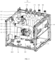
FIG. 4 is a schematic structural diagram of a hydraulic module unit of the hot water supply tank device illustrated inFIG. 1 . -
FIG. 5 is a schematic structural diagram of a water tank of the hot water supply tank device illustrated inFIG. 1 . -
FIG. 6 is a schematic diagram of an internal structure of the water tank illustrated inFIG. 1 . -
FIG. 7 is a schematic diagram of an internal structure of an electric control box of the hot water supply tank device illustrated inFIG. 1 . -
FIG. 8 is a system diagram of a heat pump heating device according to an embodiment of the present disclosure. - Reference signs of the accompanying drawings are as follows:
- 100 hot water supply tank device; 101 tank body; 102 water pan; 1021 support beam; 103 tank door;
- 10 hydraulic module unit; 1011 refrigerant inlet pipe joint; 1012 refrigerant return pipe j oint; 1211 water supply pipe joint; 1221 drainage pipe j oint; 131 second water inlet pipe joint; 132 second hot water pipe joint; 140 display and control panel;
- 11 heat exchanger; 111 refrigerant return pipe; 112 refrigerant inlet pipe;
- 12 electric auxiliary heater; 121 water outlet pipe; 122 flowmeter; 123 pressure relief valve;
- 13 water pump; 14 expansion tank; 15 water outlet pipe joint; 16 water return pipe joint;
- 171 water inlet pipe; 172 hot water pipe;
- 181 water supply pipe; 182 drainage pipe;
- 20 water tank; 201 heat supply inlet pipe; 202 heat supply return pipe; 203 first water inlet pipe joint; 204 first hot water pipe joint; 21 bottom cover; 22 barrel body; 23 top cover; 24 water temperature sensor; 25 inner coil;
- 30 electric control box; 301 box cover; 31 main control board; 32 wiring block; 33 wire clamp;
- 200 heat pump system.
- Exemplary embodiments of the present disclosure will be described in detail below with reference to the accompanying drawings. Although the exemplary embodiments of the present disclosure are illustrated in the drawings, it should be understood that the present disclosure may be embodied in various forms and should not be construed as limited to the embodiments described herein. Instead, these embodiments are provided for a thorough understanding of the present disclosure, and can fully convey the scope of the present disclosure to those skilled in the art. It should be noted that a hot water supply tank device of the present disclosure can not only supply heat through a hydraulic module unit, but also perform cooling through the hydraulic module unit. Such an adjustment falls within the scope of the hot water supply tank device of the present disclosure.
- It should be understood that terms used herein are intended to describe particular exemplary embodiments only and are not intended to be limited thereto. Unless the context clearly indicates, otherwise singular forms of "a", "one" and "said" as used herein can also be interpreted as including plural forms. Terms "include", "contain" and "have" are inclusive and therefore specify the presence of stated features, elements, and/or components, but do not preclude the presence or an addition of one or more other features, elements, components, and/or a combination thereof.
- In addition, terms "first" and "second" are only used for descriptive purposes, and cannot be understood as indicating or implying relative importance or implicitly indicating the number of indicated technical features. Therefore, the features associated with "first" and "second" may explicitly or implicitly include one or more of the features. In the description of the present disclosure, "a plurality of' means at least two, e.g., two or three, unless otherwise specifically defined.
- For ease of description, spatially relative terms, such as "top", "bottom", "inside", "top", "bottom", "side", "end", and "periphery", may be used herein to describe a relation of one element or feature illustrated in the figures to another element or feature illustrated in the figures. These spatially relative terms are intended to include different orientations of mechanisms in use or operation other than those depicted in the figures. For example, if a mechanism in the figure is flipped over, an element described as "under other elements or features" or "below other elements or features" will then be oriented as "on other elements or features" or "above other elements or features". Thus, the example term "below..." may include orientations of above and below. The mechanism may be oriented differently (e.g., rotated 90 degrees or in other directions), and may be interpreted in accordance with spatially relative descriptors used herein.
- As illustrated in
FIG. 1 to FIG. 3 , in a first aspect of the present disclosure, a hot watersupply tank device 100 is provided. The hot watersupply tank device 100 is in an integrally-formed structure, and includes atank body 101, ahydraulic module unit 10, and awater tank 20. Thetank body 101 includes a rectangular frame and a tank plate, and the tank plate is disposed on an outer wall of the frame and has a tank opening on a side of thetank body 101. Thetank body 101 further includes atank door 103 configured to expose or cover the tank opening. An interior space of thetank body 101 is defined by the frame, the tank plate, and thetank door 103. Awater pan 102 that divides the interior space of the tank body into an upper accommodation space and a lower accommodation space is further provided in thetank body 101. Thewater pan 102 is disposed on the frame. The frame is disposed on a periphery of thewater pan 102 and supports asupport beam 1021 of thewater pan 102. A pipe joint assembly is disposed above thewater pan 102. Thehydraulic module unit 10 is disposed in thetank body 101 and located in the upper accommodation space. A hydraulic pipe assembly of thehydraulic module unit 10 is connected to the pipe joint assembly. Thewater tank 20 is disposed in thetank body 101 and located in the lower accommodation space. Thewater tank 20 has a water tank pipe assembly, which extends into the pipe joint assembly and is in communication with the hydraulic pipe assembly. - In the present disclosure, the
hydraulic module unit 10 and thewater tank 20 are assembled into the integrated hot watersupply tank device 100 by means of thetank body 101. In addition, thewater pan 102 in thetank body 101 can reduce interaction between thehydraulic module unit 10 and thewater tank 20, and receive condensate water and pressure relief water vapor that are generated at thehydraulic module unit 10. Thewater pan 102 is provided with a water guide ramp, a water storage groove, and a drainage eave extending out of thetank body 101. The pipe joint assembly located above thewater pan 102 can facilitate the communication of thehydraulic module unit 10 with thewater tank 20. - It should be noted that, the
hydraulic module unit 10 is used as a heat source of thewater tank 20, such that the hydraulic module unit can not only heat the domestic water in thewater tank 20, but also heat indoor floors and cool an indoor fan coil. A structure and functions of the hot watersupply tank device 100 is described in detail below as an example that thehydraulic module unit 10 is configured to heat the domestic water in thewater tank 20. - As illustrated in
FIG. 4 , according to an embodiment of the present disclosure, thehydraulic module unit 10 includes aheat exchanger 11 and an electricauxiliary heater 12 that are in communication with each other. Theheat exchanger 11 is in communication with aheat pump system 200. Circulating water in theheat exchanger 11 absorbs heat from theheat pump system 200, undergoes a temperature rise, and then passes through the electricauxiliary heater 12 for secondary heating. The circulating water that has been subject to the secondary heating passes through awater outlet pipe 121 of the electricauxiliary heater 12 and a heatsupply inlet pipe 201 of thewater tank 20, and then flows into a heat exchange pipe of thewater tank 20. The circulating water that has been subject to the secondary heating heats the domestic water in thewater tank 20 through the heat exchange pipe, and then flows back into theheat exchanger 11 through a heatsupply return pipe 202 of thewater tank 20 and a water return pipe of theheat exchanger 11 to be re-heated. This circulation can heat the domestic water in thewater tank 20. - Specifically, the
hydraulic module unit 10 is fixed by the rectangular frame of thetank body 101. A cuboid frame is formed by assembling the rectangular frame and thesupport beam 1021 by means of metallic plates and screws, to support various members of thehydraulic module unit 10. The members of thehydraulic module unit 10 are fixed by a fixation plate. Further, the members of thehydraulic module unit 10 are connected to each other by pipe joints, pipe nuts, and copper pipes to form a completehydraulic module unit 10. - Further, in order to achieve a sealed communication of the
hydraulic module unit 10 with thewater tank 20, the pipe joint assembly of the present disclosure includes a water outlet pipe joint 15 and a water return pipe joint 16 that are both welded to atop cover 23 of thewater tank 20. Thewater outlet pipe 121 of the electricauxiliary heater 12 is communicated with the heatsupply inlet pipe 201 of thewater tank 20 by the water outlet pipe joint 15. The water return pipe of theheat exchanger 11 is communicated with the heatsupply return pipe 202 of thewater tank 20 by the water return pipe joint 16. In this way, sealed connections and reasonable layouts between thewater outlet pipe 121 and the heatsupply inlet pipe 201 and between the heatsupply return pipe 202 and the water return pipe are achieved. - It should be noted that, in the
hydraulic module unit 10, the circulating water for heating thewater tank 20 needs to be replenished and discharged periodically. To achieve the purpose of replenishing and renewing the circulating water, the hydraulic module unit according to the embodiments of the present disclosure further includes a three-way valve disposed at the heat supply inlet pipe and anexpansion tank 14 disposed at the water return pipe of theheat exchanger 11. Adrainage pipe 182 is disposed at the three-way valve. Awater supply pipe 181 is disposed on theexpansion tank 14. Replenished water can flows through the water return pipe of theheat exchanger 11 through thewater supply pipe 181 to become the circulating water, and then flows into the heat exchange pipe of thewater tank 20 through the heat supply inlet pipe. The circulating water in the heat exchange pipe can be discharged through the heat supply return pipe and thedrainage pipe 182. The three-way valve enables the heat supply inlet pipe to be switched between the water outlet pipe and thedrainage pipe 182. In addition, the use of the three-way valve can reduce numbers of the joints and the pipelines to facilitate the layout of each of the members of thehydraulic module unit 10. - Further, the
hydraulic module unit 10 and thewater tank 20 are both disposed in thetank body 101, but theheat exchanger 11 of thehydraulic module unit 10 needs to be in communication with theheat pump system 200 and thedrainage pipe 182 of thewater supply pipe 181 for the circulating water needs to be in communication with a water source outside thetank body 101. To solve the communication issue of the pipelines, in an embodiment of the present disclosure, awater supply pipe joint 1211 in communication with thewater supply pipe 181, a drainage pipe joint 1221 in communication with thedrainage pipe 182, and a refrigerant inlet pipe joint 1011 and a refrigerant return pipe joint 1012 that communicate a heat pump with theheat exchanger 11 are disposed at a top of thetank body 101, to achieve a reasonable layout of each of the pipelines and reduce interference between the pipelines. - In addition, since the domestic water in the
water tank 20 needs to flow out of thetank body 101, the hot watersupply tank device 100 further includes awater inlet pipe 171 extending into the water in thewater tank 20 and ahot water pipe 172 extending out of the water in thewater tank 20. The pipe joint assembly further includes a first water inlet pipe joint 203 in communication with thewater inlet pipe 171 and a first hot water pipe joint 204 in communication with thehot water pipe 172. A second water inlet pipe joint 131 corresponding to the first water inlet pipe joint 203 and a second hot water pipe joint 132 corresponding to the first hot water pipe joint 204 are disposed at the top of thetank body 101. The pipe joints of thewater inlet pipe 171 and thehot water pipe 172 are provided so that a reasonable layout of thewater inlet pipe 171 and thehot water pipe 172 is realized, and collisions and interference of thewater inlet pipe 171 and thehot water pipe 172 with other pipelines are reduced. - Further, the pipe joints of the
water inlet pipe 171 and thehot water pipe 172 can achieve sealing of thewater inlet pipe 171 and thehot water pipe 172 with thewater pan 102 and thetank body 101. As illustrated inFIG. 6 , thewater inlet pipe 171 extends to a bottom of the domestic water in thewater tank 20, and thehot water pipe 172 extends to a top of the domestic water in thewater tank 20. The domestic water in thewater tank 20 flows out through thehot water pipe 172 under the action of a water pressure and an air pressure in thewater tank 20, which can improve the sealing of thewater inlet pipe 171 and thehot water pipe 172 with thewater pan 102 and thewater tank 20, and facilitate the domestic water in thewater tank 20 to flow out of thewater tank 20 through thehot water pipe 172. - According to an embodiment of the present disclosure, the
hydraulic module unit 10 further includes anexpansion tank 14 and awater pump 13 that are disposed in the upper accommodation space. Theexpansion tank 14 is disposed at the water return pipe, and is configured to adjust the water pressure of the circulating water in thehydraulic module unit 10. Thewater pump 13 is disposed at the water return pipe, and is configured to improve the circulation smoothness of the circulating water in thehydraulic module unit 10. Further, theexpansion tank 14, thewater pump 13, theheat exchanger 11 and the electricauxiliary heater 12 of thehydraulic module unit 10 are disposed on a periphery of the upper accommodation space, in such a manner that a mounting space for each of the pipelines and the joints is reserved in the middle of the upper accommodation space. - According to an embodiment of the present disclosure, the
tank body 101 includes a frame and a tank plate. The tank plate is disposed on an outer wall of the frame, and has a tank opening on a side of thetank body 101. Thetank body 101 includes atank door 103 configured to expose and cover the tank opening. A display andcontrol panel 140 of the hot watersupply tank device 100 is disposed on thetank door 103. The display andcontrol panel 140 can display the operation condition and function control of the hot watersupply tank device 100. Left and right-side plates of the tank plate are fixed by screws, and may be detachably mounted if necessary. A top cover of the tank plate provides a sealing function, which prevents the water accumulated at the top from entering thehydraulic module unit 10 to cause electricity leakage. A pivot shaft is disposed at thetank door 103 to allow thetank door 103 to be freely pivoted and opened, such that it is convenient for customers to observe internal information of the hot watersupply tank device 100 and facilitate maintenance. A mounting opening for the display andcontrol panel 140 is formed on thetank door 103. - As illustrated in
FIG. 1 andFIG. 7 , according to some embodiments of the present disclosure, thehydraulic module unit 10 further includes anelectric control box 30 pivotally disposed on thetank body 101 and located in the upper accommodation space. A pivoting direction of theelectric control box 30 is opposite to a rotation direction of thetank door 103. Theelectric control box 30 is formed by assembling a box body and abox cover 301 that are fixed by screws. Pivoting hinges and rivets are provided on a side of the box body, which can realize free pivoting of theelectric control box 30 and facilitate maintenance. Another side of the box body is fixed by bolts to prevent theelectric control box 30 from falling off during transportation. Inside the box body, amain control board 31 is provided, a contactor is mounted through a slot, and electrical elements, such as a powersupply wiring block 32, awire clamp 33, and a temperature controller, are provided. Thebox cover 301 can be removed during the maintenance, to check the electrical elements inside theelectric control box 30. The pivoting of theelectric control box 30 in cooperation with thetank door 103 can facilitate the maintenance of the electrical elements inside theelectric control box 30, without removing other side plates of theelectric control box 30. - As illustrated in
FIG. 5 andFIG. 6 , according to some embodiments of the present disclosure, thewater tank 20 includes an outer housing assembly, an inner container, an insulation filling foam disposed between the outer housing assembly and the inner container, and awater temperature sensor 24 disposed at the insulation filling foam. The inner container includes an upper closure cap, an inner container barrel body, a lower closure cap, and aninner coil 25. The inner container barrel body is formed by plate-rolling welding to form a cylinder barrel body. The inner container barrel body of the inner container may be made of a hot dip galvanized steel sheet to meet corrosion resistance requirements through an enamel process, and may be used with an electronic magnesium rod. The upper and lower closure caps are formed by stretch forming using a mold, and finally are welded with the inner container barrel body. Pipe joints such as the first water inlet pipe joint 203 and the first hot water pipe joint 204 are disposed on the upper closure cap, and the lower cap has support feet. Theinner coil 25 is compactly disposed at a bottom of thewater tank 20 in a coiled structure, and realizes the heat exchange with thehydraulic module unit 10 through the circulating water and the domestic water. - The outer housing assembly of the
water tank 20 includes abottom cover 21, abarrel body 22, and atop cover 23. Thebottom cover 21 and thebarrel body 22 are assembled together by means of engagement. Thetop cover 23 is snapped at a top of thebarrel body 22 through a seal, such as a seal ring, and is connected to thebarrel body 22 by screw fixation to satisfy a requirement of precise positioning. Thewater tank 20 is fixed in a manner of fixing four metallic fixation plates at a bottom of thebottom cover 21 to a chassis of the hot watersupply tank device 100. The chassis of the hot watersupply tank device 100 is fixed to a wooden frame by bolts to facilitate the transfer of the whole device during the transportation. The wooden frame is removed after the hot watersupply tank device 100 is transported at a designated mounting site. Thewater tank 20 is placed on the chassis and fixed to the chassis by the feet on a periphery of thewater tank 20, which prevent thewater tank 20 from shaking inside the hot watersupply tank device 100, and can provide an effective support to thewater tank 20 after thewater tank 20 is filled with water. - It should be noted that, the above embodiments only describe structures of the
hydraulic module unit 10 that are relevant to improvements of the present disclosure, but this does not mean that thehydraulic module unit 10 only includes the above structures. For example, thehydraulic module unit 10 further includes aflowmeter 122 disposed at thewater outlet pipe 121 that is located at a top of the electricauxiliary heater 12, apressure relief valve 123 disposed at the top of the electricauxiliary heater 12, and a safety valve and a filter that are disposed on a pipeline. Theflowmeter 122 is configured to detect a water flow rate. The safety valve is configured to protect an in-system water pressure of the circulating water to prevent the pipeline system from being damaged due to an excessive water pressure. Thepressure relief valve 123 is configured to relieve the pressure in the electricauxiliary heater 12. The filter is configured to filter and clean in-system impurities. - Further, the
water outlet pipe 121 of the electricauxiliary heater 12 is disposed at a position close to the top of the electricauxiliary heater 12. Electric auxiliary heating elements in the electricauxiliary heater 12 are disposed in an accommodation housing and electrically connected to themain control board 31 of thehydraulic module unit 10. The top of the electric auxiliary heating elements is flush with or below thewater outlet pipe 121. Theflowmeter 122 is disposed at thewater outlet pipe 121 and electrically connected to themain control board 31. Themain control board 31 is configured to control turning on or turning off of the electric auxiliary heating elements based on the flow information detected by theflowmeter 122 to reduce occurrences of heating of the electricauxiliary heater 12 without water. - Further, the
heat exchanger 11 includes a refrigerant pipe in communication with theheat pump system 200 and a heat exchange duct in communication with the electricauxiliary heater 12 and thewater tank 20. Asecond heat exchanger 11 of theheat pump system 200 is in communication with the refrigerant pipe. The refrigerant pipe extends into theheat exchanger 11 from a top of theheat exchanger 11, and extends out of theheat exchanger 11 from a bottom of theheat exchanger 11. The refrigerant pipe is arranged at theheat exchanger 11 in a top-in and bottom-out manner. The heat exchange duct in theheat exchanger 11 is arranged in a bottom-in and top-out manner in theheat exchanger 11 to improve a heat exchange efficiency between the refrigerant pipe and the heat exchange duct. In an embodiment, a high-temperature and high-pressure gaseous refrigerant generated by theheat pump system 200 enters theheat exchanger 11 through the refrigerant pipe. A liquid refrigerant is generated subsequent to the heat exchange of the gaseous refrigerant in theheat exchanger 11, and flows out of the bottom of theheat exchanger 11. - In an embodiment, the
heat exchanger 11 is a plate-type heat exchanger. Theheat exchanger 11 includes a housing and a plurality of heat exchange sheets disposed in the housing. The refrigerant pipe and the heat exchange duct pass through the plurality of heat exchange sheets, and are in communication with each other in the housing. The refrigerant pipe extends into theheat exchanger 11 from the top of theheat exchanger 11, passes through the plurality of heat exchange sheets, and then extends out of theheat exchanger 11 from the bottom of theheat exchanger 11. The refrigerant pipe exchanges heat with the heat exchange duct of theheat exchanger 11 through the plurality of heat exchange sheets in theheat exchanger 11. - As illustrated in
FIG. 8 , in a second aspect of the present disclosure, a heat pump heating device is provided. The heat pump heating device includes theheat pump system 200 and the hot watersupply tank device 100 in the first aspect of the present disclosure. The hot watersupply tank device 100 is in communication with theheat pump system 200 through arefrigerant inlet pipe 112 and arefrigerant return pipe 111. - The
heat pump system 200 includes a compressor, a four-way valve, a first heat exchanger, a throttling device, and a second heat exchanger. The first heat exchanger and the second heat exchanger each have a heat exchange pipe structure. Theheat pump system 200 supplies heat to thehydraulic module unit 10 and thewater tank 20 through the second heat exchanger. Further, the four-way valve is controlled by themain control board 31 in theelectric control box 30. Control instructions are provided in themain control board 31. Themain control board 31 enables the compressor to heat or cool thehydraulic module unit 10 by controlling an on-off path of the four-way valve, thereby achieving free switching between the cooling and the heating. Further, a touch screen is disposed on the display andcontrol panel 140 of the hot watersupply tank device 100. The user can select a desired control instruction through the touch screen. - Since the heat pump heating device of the present disclosure includes the hot water
supply tank device 100 of the present disclosure, the heat pump heating device provides all the technical effects of the hot watersupply tank device 100, which are not described in detail herein. - While the preferred specific embodiments of the present disclosure have been described above, the scope of the present disclosure is not limited to these embodiments. Various variants and alternatives can be easily conceived by those skilled in the art without departing from the technical scope of the present disclosure. Therefore, these variants and alternatives are to be encompassed by the scope of present disclosure as defined by the claims as appended.
Claims (12)
- A hot water supply tank device, comprising:a tank body having a water pan provided in the tank body, the water pan dividing an interior space of the tank body into an upper accommodation space and a lower accommodation space, and a pipe joint assembly being arranged above the water pan;a hydraulic module unit disposed in the tank body and located in the upper accommodation space, the hydraulic module unit having a hydraulic pipe assembly connected to the pipe joint assembly; anda water tank disposed in the tank body and located in the lower accommodation space, the water tank having a water tank pipe assembly that extends into the pipe joint assembly and is in communication with the hydraulic pipe assembly.
- The hot water supply tank device according to claim 1, wherein the hydraulic module unit comprises a heat exchanger and an electric auxiliary heater that are in communication with each other;the hydraulic pipe assembly comprises a water outlet pipe of the electric auxiliary heater and a water return pipe of the heat exchanger; andthe water tank pipe assembly comprises a heat supply inlet pipe and a heat supply return pipe that are in communication with a heat exchange pipe in the water tank.
- The hot water supply tank device according to claim 2, wherein the hydraulic module unit further comprises:a three-way valve disposed at the heat supply inlet pipe; anda drainage pipe in communication with the heat supply inlet pipe through the three-way valve.
- The hot water supply tank device according to claim 3, wherein the tank body is provided with a water supply pipe j oint, a drainage pipe j oint, a refrigerant inlet pipe j oint, and a refrigerant return pipe joint at a top of the tank body,
the water supply pipe joint being in communication with a water supply pipe, the drainage pipe joint being in communication with the drainage pipe, and the refrigerant inlet pipe joint and the refrigerant return pipe joint being in communication with the heat exchanger. - The hot water supply tank device according to claim 2, wherein the hydraulic module unit further comprises:an expansion tank and a water pump that are disposed in the upper accommodation space, the expansion tank and the water pump being both disposed at the water return pipe of the heat exchanger; anda water supply pipe in communication with the water return pipe through the expansion tank.
- The hot water supply tank device according to any one of claims 1 to 5, wherein the tank body comprises:a frame;a tank plate disposed on an outer wall of the frame and having an opening formed on a side of the tank body; anda tank door configured to expose or cover the opening and provided with a display and control panel of the hot water supply tank device.
- The hot water supply tank device according to claim 6, wherein the water pan is disposed on the frame; and
the frame is disposed on a periphery of the water pan and configured to support a support beam of the water pan. - The hot water supply tank device according to claim 6, wherein the hydraulic module unit further comprises:
an electric control box rotatably disposed on the tank body and located at the upper accommodation space, a rotation direction of the electric control box being opposite to a pivoting direction of the tank door. - The hot water supply tank device according to claim 1, further comprising:a water inlet pipe extending into water in the water tank; anda hot water pipe extending out of the water in the water tank,wherein the pipe joint assembly comprises a first water inlet pipe joint in communication with the water inlet pipe and a first hot water pipe joint in communication with the hot water pipe.
- The hot water supply tank device according to claim 9, wherein the tank body is provided with a second water inlet pipe joint and a second hot water pipe joint at a top of the tank body, the second water inlet pipe joint corresponding to the first water inlet pipe j oint, and the second hot water pipe joint corresponding to the first hot water pipe joint.
- The hot water supply tank device according to claim 2, wherein the water tank comprises an outer housing assembly and an inner housing assembly, the outer housing assembly comprising a bottom cover, a barrel body engaged on the bottom cover, and a top cover snapped at a top of the barrel body through a seal; and
the heat exchange pipe is an inner coil disposed in the barrel body. - A heat pump heating device, comprising:a heat pump system; andthe hot water supply tank device according to any one of claims 1 to 11,wherein the hot water supply tank device is in communication with the heat pump system through a refrigerant inlet pipe and a refrigerant return pipe.
Applications Claiming Priority (2)
| Application Number | Priority Date | Filing Date | Title |
|---|---|---|---|
| CN202120488090.9U CN215260045U (en) | 2021-03-05 | 2021-03-05 | Water supply tank equipment and heat pump heating equipment with same |
| PCT/CN2021/140811 WO2022183815A1 (en) | 2021-03-05 | 2021-12-23 | Hot water supply tank device and heat pump heating device having same |
Publications (2)
| Publication Number | Publication Date |
|---|---|
| EP4290142A1 true EP4290142A1 (en) | 2023-12-13 |
| EP4290142A4 EP4290142A4 (en) | 2024-07-24 |
Family
ID=79503188
Family Applications (1)
| Application Number | Title | Priority Date | Filing Date |
|---|---|---|---|
| EP21928886.7A Pending EP4290142A4 (en) | 2021-03-05 | 2021-12-23 | HOT WATER SUPPLY TANK DEVICE AND HEAT PUMP HEATING DEVICE |
Country Status (3)
| Country | Link |
|---|---|
| EP (1) | EP4290142A4 (en) |
| CN (1) | CN215260045U (en) |
| WO (1) | WO2022183815A1 (en) |
Cited By (2)
| Publication number | Priority date | Publication date | Assignee | Title |
|---|---|---|---|---|
| WO2025228820A1 (en) * | 2024-04-30 | 2025-11-06 | Qvantum Industries Ab | A method for controlling input of a heated fluid received from a heat pump to a buffer tank of a heat pump arrangement |
| WO2025228818A1 (en) * | 2024-04-30 | 2025-11-06 | Qvantum Industries Ab | A branching conduit module for a heat pump arrangement, a buffer tank assembly, and a heat pump arrangement |
Families Citing this family (5)
| Publication number | Priority date | Publication date | Assignee | Title |
|---|---|---|---|---|
| CN215260045U (en) * | 2021-03-05 | 2021-12-21 | 合肥美的暖通设备有限公司 | Water supply tank equipment and heat pump heating equipment with same |
| DE102023105991A1 (en) * | 2023-03-10 | 2024-09-12 | Stiebel Eltron Gmbh & Co. Kg | Hot water heat pump |
| EP4724743A1 (en) * | 2023-06-08 | 2026-04-15 | Rinnai Corporation | Hot water system with heat pump |
| CN116567985A (en) * | 2023-06-09 | 2023-08-08 | 广东爱尼智能家电制造有限公司 | A flip-up electric control box installation structure and heat pump equipment using the structure |
| CN119042803B (en) * | 2024-11-01 | 2025-02-11 | 山东中科蓝天科技有限公司 | Protection device for air source heat pump water heater |
Family Cites Families (10)
| Publication number | Priority date | Publication date | Assignee | Title |
|---|---|---|---|---|
| CN205747132U (en) * | 2016-05-17 | 2016-11-30 | 广东美的暖通设备有限公司 | Hydraulic module |
| CN107228425A (en) * | 2017-06-23 | 2017-10-03 | Tcl空调器(中山)有限公司 | Hydraulic module and air conditioning system |
| EP3462106B1 (en) * | 2017-09-28 | 2020-12-02 | Daikin Industries, Ltd. | Hot-water supply unit and maintenance method for a heating mechanism of the same |
| CN208296310U (en) * | 2018-05-21 | 2018-12-28 | 广东美的暖通设备有限公司 | Hydraulic module and heat pump system with it |
| CN108758913A (en) * | 2018-06-20 | 2018-11-06 | 广东美的暖通设备有限公司 | Combined-type water power module unit and heat pump system |
| EP3705820B1 (en) * | 2019-03-08 | 2021-11-03 | Daikin Industries, Ltd. | Heat source unit for a heat pump |
| CN110779130B (en) * | 2019-11-04 | 2021-12-03 | 广东美的暖通设备有限公司 | Hydraulic device and hot water air conditioner |
| WO2022137536A1 (en) * | 2020-12-25 | 2022-06-30 | 三菱電機株式会社 | Heat-pump water heater, heat pump device equipped with heat-pump water heater, and method for assembling heat-pump water heater |
| CN215260045U (en) * | 2021-03-05 | 2021-12-21 | 合肥美的暖通设备有限公司 | Water supply tank equipment and heat pump heating equipment with same |
| CN214581414U (en) * | 2021-03-05 | 2021-11-02 | 合肥美的暖通设备有限公司 | Hydraulic module unit, hot water supply tank equipment with same and heat pump heating equipment |
-
2021
- 2021-03-05 CN CN202120488090.9U patent/CN215260045U/en active Active
- 2021-12-23 WO PCT/CN2021/140811 patent/WO2022183815A1/en not_active Ceased
- 2021-12-23 EP EP21928886.7A patent/EP4290142A4/en active Pending
Cited By (2)
| Publication number | Priority date | Publication date | Assignee | Title |
|---|---|---|---|---|
| WO2025228820A1 (en) * | 2024-04-30 | 2025-11-06 | Qvantum Industries Ab | A method for controlling input of a heated fluid received from a heat pump to a buffer tank of a heat pump arrangement |
| WO2025228818A1 (en) * | 2024-04-30 | 2025-11-06 | Qvantum Industries Ab | A branching conduit module for a heat pump arrangement, a buffer tank assembly, and a heat pump arrangement |
Also Published As
| Publication number | Publication date |
|---|---|
| EP4290142A4 (en) | 2024-07-24 |
| CN215260045U (en) | 2021-12-21 |
| WO2022183815A1 (en) | 2022-09-09 |
Similar Documents
| Publication | Publication Date | Title |
|---|---|---|
| WO2022183815A1 (en) | Hot water supply tank device and heat pump heating device having same | |
| US7823799B2 (en) | Heat-pump-type water heater | |
| CN214581414U (en) | Hydraulic module unit, hot water supply tank equipment with same and heat pump heating equipment | |
| CN204810780U (en) | Adopt quick -witted case and server component of double -phase formula immersion cooling | |
| WO2021077802A1 (en) | Integrated air source heat pump | |
| EP4532990A1 (en) | Heat pump unit, assembly of a heat pump unit and a tank and a method of installing a heat pump unit and a tank | |
| WO2011132249A1 (en) | Water heater | |
| JP2010281487A (en) | Water heater | |
| US20140138390A1 (en) | Hot water storage tank unit | |
| RU2823405C2 (en) | Hot water supply tank device and heating device with heat pump, having in its composition said device | |
| CN219572141U (en) | Heat pump outdoor unit | |
| CN214581415U (en) | Water supply tank, water supply tank device with same and heat pump heating device | |
| KR101610383B1 (en) | Indoor unit of Water circulation system associated with refrigerant cycle | |
| JP5845441B2 (en) | Heat pump water heater | |
| WO2022137536A1 (en) | Heat-pump water heater, heat pump device equipped with heat-pump water heater, and method for assembling heat-pump water heater | |
| CN107036285A (en) | Heat pump water heater | |
| CN107023989A (en) | Heat pump water-heating machine | |
| JP2004020026A (en) | Hot water storage type bath hot water supply device with heating function | |
| US20250334295A1 (en) | Drain plug and heat pump | |
| CN118935802B (en) | HVAC equipment | |
| JP7671590B2 (en) | Refrigeration equipment | |
| CN222507772U (en) | Energy storage cabinet air conditioning unit and energy storage cabinet | |
| US20250290707A1 (en) | Apparatus, system and method | |
| CN221172384U (en) | Integrated heat supply station of closed gas module furnace | |
| CN215216436U (en) | Water supply tank, water supply tank device with same and heat pump heating device |
Legal Events
| Date | Code | Title | Description |
|---|---|---|---|
| STAA | Information on the status of an ep patent application or granted ep patent |
Free format text: STATUS: THE INTERNATIONAL PUBLICATION HAS BEEN MADE |
|
| PUAI | Public reference made under article 153(3) epc to a published international application that has entered the european phase |
Free format text: ORIGINAL CODE: 0009012 |
|
| STAA | Information on the status of an ep patent application or granted ep patent |
Free format text: STATUS: REQUEST FOR EXAMINATION WAS MADE |
|
| 17P | Request for examination filed |
Effective date: 20230906 |
|
| AK | Designated contracting states |
Kind code of ref document: A1 Designated state(s): AL AT BE BG CH CY CZ DE DK EE ES FI FR GB GR HR HU IE IS IT LI LT LU LV MC MK MT NL NO PL PT RO RS SE SI SK SM TR |
|
| DAV | Request for validation of the european patent (deleted) | ||
| DAX | Request for extension of the european patent (deleted) | ||
| A4 | Supplementary search report drawn up and despatched |
Effective date: 20240620 |
|
| RIC1 | Information provided on ipc code assigned before grant |
Ipc: F24H 9/20 20220101ALI20240614BHEP Ipc: F24H 4/04 20060101ALI20240614BHEP Ipc: F24H 9/16 20220101ALI20240614BHEP Ipc: F24H 9/02 20060101ALI20240614BHEP Ipc: F24H 9/14 20060101ALI20240614BHEP Ipc: F24H 4/02 20220101ALI20240614BHEP Ipc: F24H 9/00 20220101ALI20240614BHEP Ipc: F24D 15/04 20060101ALI20240614BHEP Ipc: F24D 19/00 20060101AFI20240614BHEP |
|
| STAA | Information on the status of an ep patent application or granted ep patent |
Free format text: STATUS: EXAMINATION IS IN PROGRESS |
|
| 17Q | First examination report despatched |
Effective date: 20260303 |