EP4290101A2 - Piston ring - Google Patents
Piston ring Download PDFInfo
- Publication number
- EP4290101A2 EP4290101A2 EP23192651.0A EP23192651A EP4290101A2 EP 4290101 A2 EP4290101 A2 EP 4290101A2 EP 23192651 A EP23192651 A EP 23192651A EP 4290101 A2 EP4290101 A2 EP 4290101A2
- Authority
- EP
- European Patent Office
- Prior art keywords
- layer
- piston ring
- chrome
- dlc
- chromium
- Prior art date
- Legal status (The legal status is an assumption and is not a legal conclusion. Google has not performed a legal analysis and makes no representation as to the accuracy of the status listed.)
- Pending
Links
- VYZAMTAEIAYCRO-UHFFFAOYSA-N Chromium Chemical compound [Cr] VYZAMTAEIAYCRO-UHFFFAOYSA-N 0.000 claims abstract description 49
- UFHFLCQGNIYNRP-UHFFFAOYSA-N Hydrogen Chemical compound [H][H] UFHFLCQGNIYNRP-UHFFFAOYSA-N 0.000 claims abstract description 5
- 238000004519 manufacturing process Methods 0.000 claims abstract description 5
- 239000001257 hydrogen Substances 0.000 claims abstract description 4
- 229910052739 hydrogen Inorganic materials 0.000 claims abstract description 4
- 238000000034 method Methods 0.000 claims description 19
- 229910052804 chromium Inorganic materials 0.000 claims description 15
- 239000011651 chromium Substances 0.000 claims description 15
- 230000002093 peripheral effect Effects 0.000 claims description 5
- 239000002245 particle Substances 0.000 claims description 4
- 229910001220 stainless steel Inorganic materials 0.000 claims description 2
- 238000005240 physical vapour deposition Methods 0.000 description 5
- 238000002485 combustion reaction Methods 0.000 description 3
- 229910000669 Chrome steel Inorganic materials 0.000 description 2
- 230000015572 biosynthetic process Effects 0.000 description 2
- 239000011248 coating agent Substances 0.000 description 2
- 238000000576 coating method Methods 0.000 description 2
- 230000003247 decreasing effect Effects 0.000 description 2
- 230000002349 favourable effect Effects 0.000 description 2
- 230000007704 transition Effects 0.000 description 2
- 229910000831 Steel Inorganic materials 0.000 description 1
- 238000011161 development Methods 0.000 description 1
- 230000018109 developmental process Effects 0.000 description 1
- 230000000694 effects Effects 0.000 description 1
- 239000003792 electrolyte Substances 0.000 description 1
- 238000005516 engineering process Methods 0.000 description 1
- 238000005461 lubrication Methods 0.000 description 1
- 238000007747 plating Methods 0.000 description 1
- 238000000926 separation method Methods 0.000 description 1
- 239000010959 steel Substances 0.000 description 1
- 239000000126 substance Substances 0.000 description 1
- 238000009423 ventilation Methods 0.000 description 1
Images
Classifications
-
- C—CHEMISTRY; METALLURGY
- C23—COATING METALLIC MATERIAL; COATING MATERIAL WITH METALLIC MATERIAL; CHEMICAL SURFACE TREATMENT; DIFFUSION TREATMENT OF METALLIC MATERIAL; COATING BY VACUUM EVAPORATION, BY SPUTTERING, BY ION IMPLANTATION OR BY CHEMICAL VAPOUR DEPOSITION, IN GENERAL; INHIBITING CORROSION OF METALLIC MATERIAL OR INCRUSTATION IN GENERAL
- C23C—COATING METALLIC MATERIAL; COATING MATERIAL WITH METALLIC MATERIAL; SURFACE TREATMENT OF METALLIC MATERIAL BY DIFFUSION INTO THE SURFACE, BY CHEMICAL CONVERSION OR SUBSTITUTION; COATING BY VACUUM EVAPORATION, BY SPUTTERING, BY ION IMPLANTATION OR BY CHEMICAL VAPOUR DEPOSITION, IN GENERAL
- C23C28/00—Coating for obtaining at least two superposed coatings either by methods not provided for in a single one of groups C23C2/00 - C23C26/00 or by combinations of methods provided for in subclasses C23C and C25C or C25D
- C23C28/30—Coatings combining at least one metallic layer and at least one inorganic non-metallic layer
- C23C28/34—Coatings combining at least one metallic layer and at least one inorganic non-metallic layer including at least one inorganic non-metallic material layer, e.g. metal carbide, nitride, boride, silicide layer and their mixtures, enamels, phosphates and sulphates
- C23C28/343—Coatings combining at least one metallic layer and at least one inorganic non-metallic layer including at least one inorganic non-metallic material layer, e.g. metal carbide, nitride, boride, silicide layer and their mixtures, enamels, phosphates and sulphates with at least one DLC or an amorphous carbon based layer, the layer being doped or not
-
- F—MECHANICAL ENGINEERING; LIGHTING; HEATING; WEAPONS; BLASTING
- F16—ENGINEERING ELEMENTS AND UNITS; GENERAL MEASURES FOR PRODUCING AND MAINTAINING EFFECTIVE FUNCTIONING OF MACHINES OR INSTALLATIONS; THERMAL INSULATION IN GENERAL
- F16J—PISTONS; CYLINDERS; SEALINGS
- F16J9/00—Piston-rings, e.g. non-metallic piston-rings, seats therefor; Ring sealings of similar construction
- F16J9/26—Piston-rings, e.g. non-metallic piston-rings, seats therefor; Ring sealings of similar construction characterised by the use of particular materials
-
- C—CHEMISTRY; METALLURGY
- C23—COATING METALLIC MATERIAL; COATING MATERIAL WITH METALLIC MATERIAL; CHEMICAL SURFACE TREATMENT; DIFFUSION TREATMENT OF METALLIC MATERIAL; COATING BY VACUUM EVAPORATION, BY SPUTTERING, BY ION IMPLANTATION OR BY CHEMICAL VAPOUR DEPOSITION, IN GENERAL; INHIBITING CORROSION OF METALLIC MATERIAL OR INCRUSTATION IN GENERAL
- C23C—COATING METALLIC MATERIAL; COATING MATERIAL WITH METALLIC MATERIAL; SURFACE TREATMENT OF METALLIC MATERIAL BY DIFFUSION INTO THE SURFACE, BY CHEMICAL CONVERSION OR SUBSTITUTION; COATING BY VACUUM EVAPORATION, BY SPUTTERING, BY ION IMPLANTATION OR BY CHEMICAL VAPOUR DEPOSITION, IN GENERAL
- C23C14/00—Coating by vacuum evaporation, by sputtering or by ion implantation of the coating forming material
- C23C14/06—Coating by vacuum evaporation, by sputtering or by ion implantation of the coating forming material characterised by the coating material
- C23C14/0605—Carbon
-
- C—CHEMISTRY; METALLURGY
- C23—COATING METALLIC MATERIAL; COATING MATERIAL WITH METALLIC MATERIAL; CHEMICAL SURFACE TREATMENT; DIFFUSION TREATMENT OF METALLIC MATERIAL; COATING BY VACUUM EVAPORATION, BY SPUTTERING, BY ION IMPLANTATION OR BY CHEMICAL VAPOUR DEPOSITION, IN GENERAL; INHIBITING CORROSION OF METALLIC MATERIAL OR INCRUSTATION IN GENERAL
- C23C—COATING METALLIC MATERIAL; COATING MATERIAL WITH METALLIC MATERIAL; SURFACE TREATMENT OF METALLIC MATERIAL BY DIFFUSION INTO THE SURFACE, BY CHEMICAL CONVERSION OR SUBSTITUTION; COATING BY VACUUM EVAPORATION, BY SPUTTERING, BY ION IMPLANTATION OR BY CHEMICAL VAPOUR DEPOSITION, IN GENERAL
- C23C28/00—Coating for obtaining at least two superposed coatings either by methods not provided for in a single one of groups C23C2/00 - C23C26/00 or by combinations of methods provided for in subclasses C23C and C25C or C25D
- C23C28/30—Coatings combining at least one metallic layer and at least one inorganic non-metallic layer
- C23C28/32—Coatings combining at least one metallic layer and at least one inorganic non-metallic layer including at least one pure metallic layer
- C23C28/322—Coatings combining at least one metallic layer and at least one inorganic non-metallic layer including at least one pure metallic layer only coatings of metal elements only
-
- C—CHEMISTRY; METALLURGY
- C23—COATING METALLIC MATERIAL; COATING MATERIAL WITH METALLIC MATERIAL; CHEMICAL SURFACE TREATMENT; DIFFUSION TREATMENT OF METALLIC MATERIAL; COATING BY VACUUM EVAPORATION, BY SPUTTERING, BY ION IMPLANTATION OR BY CHEMICAL VAPOUR DEPOSITION, IN GENERAL; INHIBITING CORROSION OF METALLIC MATERIAL OR INCRUSTATION IN GENERAL
- C23C—COATING METALLIC MATERIAL; COATING MATERIAL WITH METALLIC MATERIAL; SURFACE TREATMENT OF METALLIC MATERIAL BY DIFFUSION INTO THE SURFACE, BY CHEMICAL CONVERSION OR SUBSTITUTION; COATING BY VACUUM EVAPORATION, BY SPUTTERING, BY ION IMPLANTATION OR BY CHEMICAL VAPOUR DEPOSITION, IN GENERAL
- C23C28/00—Coating for obtaining at least two superposed coatings either by methods not provided for in a single one of groups C23C2/00 - C23C26/00 or by combinations of methods provided for in subclasses C23C and C25C or C25D
- C23C28/30—Coatings combining at least one metallic layer and at least one inorganic non-metallic layer
- C23C28/34—Coatings combining at least one metallic layer and at least one inorganic non-metallic layer including at least one inorganic non-metallic material layer, e.g. metal carbide, nitride, boride, silicide layer and their mixtures, enamels, phosphates and sulphates
- C23C28/347—Coatings combining at least one metallic layer and at least one inorganic non-metallic layer including at least one inorganic non-metallic material layer, e.g. metal carbide, nitride, boride, silicide layer and their mixtures, enamels, phosphates and sulphates with layers adapted for cutting tools or wear applications
-
- C—CHEMISTRY; METALLURGY
- C25—ELECTROLYTIC OR ELECTROPHORETIC PROCESSES; APPARATUS THEREFOR
- C25D—PROCESSES FOR THE ELECTROLYTIC OR ELECTROPHORETIC PRODUCTION OF COATINGS; ELECTROFORMING; APPARATUS THEREFOR
- C25D15/00—Electrolytic or electrophoretic production of coatings containing embedded materials, e.g. particles, whiskers, wires
-
- C—CHEMISTRY; METALLURGY
- C25—ELECTROLYTIC OR ELECTROPHORETIC PROCESSES; APPARATUS THEREFOR
- C25D—PROCESSES FOR THE ELECTROLYTIC OR ELECTROPHORETIC PRODUCTION OF COATINGS; ELECTROFORMING; APPARATUS THEREFOR
- C25D5/00—Electroplating characterised by the process; Pretreatment or after-treatment of workpieces
- C25D5/48—After-treatment of electroplated surfaces
-
- C—CHEMISTRY; METALLURGY
- C25—ELECTROLYTIC OR ELECTROPHORETIC PROCESSES; APPARATUS THEREFOR
- C25D—PROCESSES FOR THE ELECTROLYTIC OR ELECTROPHORETIC PRODUCTION OF COATINGS; ELECTROFORMING; APPARATUS THEREFOR
- C25D3/00—Electroplating: Baths therefor
- C25D3/02—Electroplating: Baths therefor from solutions
- C25D3/04—Electroplating: Baths therefor from solutions of chromium
-
- F—MECHANICAL ENGINEERING; LIGHTING; HEATING; WEAPONS; BLASTING
- F02—COMBUSTION ENGINES; HOT-GAS OR COMBUSTION-PRODUCT ENGINE PLANTS
- F02F—CYLINDERS, PISTONS OR CASINGS, FOR COMBUSTION ENGINES; ARRANGEMENTS OF SEALINGS IN COMBUSTION ENGINES
- F02F5/00—Piston rings, e.g. associated with piston crown
Definitions
- the invention relates to a piston ring.
- a piston ring which has a DLC layer on the running surface, in other words the lateral surface, particularly with a view to good wear behavior.
- the flank surfaces are nitrided, but can have a coating.
- the DE 10 2007 038 188 A1 relates to a piston ring with a galvanic chrome layer on which a PVD layer is applied.
- the invention is based on the object of creating a piston ring that is improved in terms of wear behavior and/or friction and/or manufacturing effort.
- the top layer of the tread being a DLC layer
- the top layer of at least one flank surface being a chrome layer.
- at least the lower flank surface in other words that flank surface of a piston ring which is intended to face away from the combustion chamber, is coated.
- the second flank surface can be uncoated or coated, in particular provided with a chrome layer.
- the DLC layer on the tread ensures low wear and comparatively low friction and is also fireproof.
- the chrome layer on at least one flank surface is easier and cheaper to apply, for example compared to a DLC layer, and also ensures little wear in this area.
- the reduced wear is also with regard to the so-called blow-by, in other words an unwanted one Oil flow past the oil scraper ring, relevant.
- High wear on the lower flanks of piston rings in the first groove causes increased blow-by. If this exceeds the oil separation effect of the engine ventilation, oil is transported out of the crankcase via the blow-by flow and the engine's oil consumption increases to an unacceptable extent.
- the flank surfaces wear too much, the piston ring in the groove can twist with the running surface downwards under load, so that the lower edge of the running surface has a harder time wiping off oil and oil consumption increases.
- the piston ring can break due to excessive axial play in the groove.
- DLC layer Particularly favorable properties are expected for the DLC layer if it is hydrogen-free, but in certain applications a hydrogen-containing DLC layer can also be advantageous.
- the DLC layer can be formed in areas on a chrome layer. This applies to both running and flank surfaces.
- the DLC layer at least partially overlaps the chrome layer in the area of the peripheral edges.
- the chrome layer can taper towards the peripheral edge, and/or the peripheral edges can be machined at a defined angle.
- a PVD (Physical Vapor Deposition) process is preferred.
- the chrome layer has a hardness of at least 800 HV 0.1.
- the crack network density of the chromium layer it is preferred, particularly with regard to the possible particle inclusions, that it has a crack rate of 700 to 1200 cracks/cm.
- a coefficient of friction in the lubricated friction contact is preferred for the chrome layer, which is at least 20% lower than that of nitrided chrome steel.
- the chrome layer can be processed, preferably combined with galvanic application, in such a way that the roughness of the flank surfaces is subsequently less than Rz 4.
- the chromium layer can have particle inclusions, which can in particular be embedded in the crack network of the chromium layer.
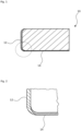
- a piston ring 10 typically has a rectangular cross section with a running surface 12 and flank surfaces that run essentially perpendicular thereto, of which the lower flank surface is designated 14.
- the lower flank surface 14 is provided with a chrome layer and the tread with a DLC layer.
- the preferred measure is shown here, according to which the DLC layer overlaps the chrome layer, particularly in the transition area between the running surface 12 and the flank surface 14. In the example shown, the transition is rounded, but it can also be oblique.
- chrome layer extends with decreasing thickness up to (in the Figures vertical) tread 12, and the DLC layer also with decreasing thickness approximately up to the beginning of the flank surface 14 (horizontal in the figures).
Abstract
Ein Kolbenring (10) weist eine Lauffläche (12) und Flankenflächen (14) auf, die beschichtet sind, wobei die oberste Schicht der Lauffläche (12) eine wasserstoffhaltige oder wasserstofffreie DLC-Schicht ist, und dadurch gekennzeichnet ist, dass die oberste Schicht zumindest einer Flankenfläche (14) eine Chromschicht ist.Bei einem Verfahren zur Herstellung eines Kolbenrings (10) wird als oberste Schicht der Lauffläche (12) eine DLC-Schicht, und als oberste Schicht zumindest einer Flankenfläche (14) eine Chromschicht ausgebildet.A piston ring (10) has a running surface (12) and flank surfaces (14) which are coated, the top layer of the running surface (12) being a hydrogen-containing or hydrogen-free DLC layer, and is characterized in that the top layer is at least a flank surface (14) is a chrome layer. In a method for producing a piston ring (10), a DLC layer is formed as the top layer of the running surface (12), and a chrome layer is formed as the top layer of at least one flank surface (14).
Description
Die Erfindung betrifft einen Kolbenring.The invention relates to a piston ring.
An Kolbenringe von Verbrennungsmotoren werden hohe Anforderungen im Hinblick auf einen möglichst geringen Verschleiß und eine möglichst geringe Reibung gestellt.High demands are placed on piston rings of internal combustion engines with regard to the lowest possible wear and the lowest possible friction.
Aus der
Die
Vor diesem Hintergrund liegt der Erfindung die Aufgabe zugrunde, einen im Hinblick auf das Verschleißverhalten und/oder die Reibung und/oder den Herstellungsaufwand verbesserten Kolbenring zu schaffen.Against this background, the invention is based on the object of creating a piston ring that is improved in terms of wear behavior and/or friction and/or manufacturing effort.
Die Lösung dieser Aufgabe erfolgt durch den in Anspruch 1 beschriebenen Kolbenring.This problem is solved by the piston ring described in claim 1.
Demzufolge weist dieser beschichtete Lauf- und Flankenflächen auf, wobei die oberste Schicht der Lauffläche eine DLC-Schicht ist, und die oberste Schicht zumindest einer Flankenfläche eine Chromschicht ist. Bevorzugt ist zumindest die untere Flankenfläche, mit anderen Worten diejenige Flankenfläche eines Kolbenrings, die dafür vorgesehen ist, von dem Brennraum abgewandt zu sein, beschichtet. Die zweite Flankenfläche kann unbeschichtet oder beschichtet, insbesondere mit einer Chromschicht versehen sein. Die DLC-Schicht auf der Lauffläche sorgt für einen geringen Verschleiß und eine vergleichsweise geringe Reibung und ist darüber hinaus brandspurfest. Die Chromschicht auf zumindest einer Flankenfläche ist, beispielsweise verglichen mit einer DLC-Schicht, einfacher und kostengünstiger aufbringbar und sorgt darüber hinaus für einen geringen Verschleiß in diesem Bereich.As a result, it has coated running and flank surfaces, the top layer of the tread being a DLC layer, and the top layer of at least one flank surface being a chrome layer. Preferably, at least the lower flank surface, in other words that flank surface of a piston ring which is intended to face away from the combustion chamber, is coated. The second flank surface can be uncoated or coated, in particular provided with a chrome layer. The DLC layer on the tread ensures low wear and comparatively low friction and is also fireproof. The chrome layer on at least one flank surface is easier and cheaper to apply, for example compared to a DLC layer, and also ensures little wear in this area.
Darüber hinaus wird in Verbrennungsmotoren allgemein das Thema der Reibungsverminderung immer wichtiger, wozu die Chromschicht auf zumindest einer Flankenfläche einen vorteilhaften Beitrag leistet. Infolge der Bewegung des Kolbenrings im Betrieb ergibt sich nämlich auch hier Axial- und/oder Radialreibung, für die erwartet wird, dass sie mit der erfindungsgemäßen Chromschicht vergleichsweise gering ausfällt. Ferner ergibt sich verglichen mit nitrierten Flanken der Vorteil eines geringeren Verschleißes sowohl der Flankenflächen des Kolbenrings als auch der Kolbenringnut, insbesondere bei hoher Belastung und/oder ungünstigen Schmierbedingungen. Bei Versuchen konnte mit einem Stahlkolben für die erfindungsgemäße Chrombeschichtung verglichen mit nitriertem Chromstahl ein um mehr als 50% verringerter Verschleiß und eine deutlich verringerte Reibung festgestellt werden.In addition, the issue of reducing friction is becoming increasingly important in internal combustion engines, to which the chromium layer on at least one flank surface makes an advantageous contribution. As a result of the movement of the piston ring during operation, axial and/or radial friction also arises here, which is expected to be comparatively low with the chromium layer according to the invention. Furthermore, compared to nitrided flanks, there is the advantage of less wear on both the flank surfaces of the piston ring and the piston ring groove, especially under high loads and/or unfavorable lubrication conditions. In tests with a steel piston for the chromium coating according to the invention, wear was reduced by more than 50% and friction was significantly reduced compared to nitrided chromium steel.
Der verringerte Verschleiß ist auch im Hinblick auf das sogenannte blow-by, mit anderen Worten einem ungewollten Ölstrom an dem Ölabstreifring vorbei, relevant. Ein hoher Verschleiß der Unterflanken von Kolbenringen in der ersten Nut verursacht nämlich ein erhöhtes blow-by. Wenn dieses die Ölabscheidewirkung der Motorentlüftung übersteigt, wird über den blow-by-Strom Öl aus dem Kurbelgehäuse transportiert, und der Ölverbrauch des Motors steigt in unzulässiger Weise an. Ferner kann sich der Kolbenring in der Nut bei zu hohem Verschleiß der Flankenflächen mit der Lauffläche nach unten bei Belastung verdrehen, so dass die untere Kante der Lauffläche Öl schlechter abstreift, und der Ölverbrauch ansteigt. Schließlich kann bei einem extremen Verschleiß der Flankenflächen, gegebenenfalls in Kombination mit einem Verschleiß der Kolbenringnut, der Kolbenring aufgrund eines zu hohen axialen Spiels in der Nut brechen.The reduced wear is also with regard to the so-called blow-by, in other words an unwanted one Oil flow past the oil scraper ring, relevant. High wear on the lower flanks of piston rings in the first groove causes increased blow-by. If this exceeds the oil separation effect of the engine ventilation, oil is transported out of the crankcase via the blow-by flow and the engine's oil consumption increases to an unacceptable extent. Furthermore, if the flank surfaces wear too much, the piston ring in the groove can twist with the running surface downwards under load, so that the lower edge of the running surface has a harder time wiping off oil and oil consumption increases. Finally, in the event of extreme wear of the flank surfaces, possibly in combination with wear of the piston ring groove, the piston ring can break due to excessive axial play in the groove.
Bevorzugte Weiterbildungen des erfindungsgemäßen Kolbenrings gehen aus den weiteren Ansprüchen hervor.Preferred developments of the piston ring according to the invention emerge from the further claims.
Für die DLC-Schicht werden besonders günstige Eigenschaften erwartet, wenn sie wasserstofffrei ist, in bestimmten Anwendungsfällen kann jedoch auch eine wasserstoffhaltige DLC-Schicht vorteilhaft sein.Particularly favorable properties are expected for the DLC layer if it is hydrogen-free, but in certain applications a hydrogen-containing DLC layer can also be advantageous.
Nachdem es prozesstechnisch Vorteile bietet, die Chromschicht zuerst auszubilden, kann die DLC-Schicht bereichsweise auf einer Chromschicht ausgebildet sein. Dies gilt sowohl für Lauf- als auch Flankenflächen.Since it offers process technology advantages to form the chrome layer first, the DLC layer can be formed in areas on a chrome layer. This applies to both running and flank surfaces.
Insbesondere kann es für die Herstellung Vorteile bieten, wenn die DLC-Schicht die Chromschicht im Bereich der Umfangskanten zumindest teilweise überlappt. Hierbei kann die Chromschicht zu der Umfangskante hin auslaufen, und/oder die Umfangskanten können unter einem definierten Winkel bearbeitet sein.In particular, it can offer advantages for production if the DLC layer at least partially overlaps the chrome layer in the area of the peripheral edges. Here, the chrome layer can taper towards the peripheral edge, and/or the peripheral edges can be machined at a defined angle.
Im Hinblick auf die Ausbildung der DLC-Schicht wird ein PVD (Physical Vapour Deposition)-Verfahren bevorzugt.With regard to the formation of the DLC layer, a PVD (Physical Vapor Deposition) process is preferred.
Besondere Vorteile, insbesondere im Hinblick auf einen geringen Verschleiß werden erwartet, wenn die Chromschicht eine Härte von mindestens 800 HV 0,1 aufweist.Particular advantages, particularly with regard to low wear, are expected if the chrome layer has a hardness of at least 800 HV 0.1.
Für die Rissnetzdichte der Chromschicht wird insbesondere im Hinblick auf die möglichen Partikeleinlagerungen bevorzugt, dass diese eine Rissrate von 700 bis 1200 Risse/cm aufweist.For the crack network density of the chromium layer, it is preferred, particularly with regard to the possible particle inclusions, that it has a crack rate of 700 to 1200 cracks/cm.
Im Hinblick auf eine konkrete Verringerung der Reibung im Bereich der Flankenflächen wird für die Chromschicht ein Reibkoeffizient im geschmierten Reibkontakt bevorzugt, der zumindest 20% geringer ist als der von nitriertem Chromstahl.With regard to a concrete reduction in friction in the area of the flank surfaces, a coefficient of friction in the lubricated friction contact is preferred for the chrome layer, which is at least 20% lower than that of nitrided chrome steel.
Aufgrund günstiger Erfahrungen wird für die Herstellung der Chromschicht eine galvanische Ausbildung bevorzugt.Due to favorable experience, galvanic training is preferred for producing the chrome layer.
Insbesondere kann hierbei eine Bearbeitung der Chromschicht, bevorzugt kombiniert mit einer galvanischen Aufbringung, derart erfolgen, dass die Rauheit der Flankenflächen nachfolgend geringer als Rz 4 ist.In particular, the chrome layer can be processed, preferably combined with galvanic application, in such a way that the roughness of the flank surfaces is subsequently less than Rz 4.
Zur weiteren Verbesserung ihrer Eigenschaften, kann die Chromschicht Partikeleinlagerungen aufweisen, die insbesondere in das Rissnetzwerk der Chromschicht eingelagert sein können.To further improve its properties, the chromium layer can have particle inclusions, which can in particular be embedded in the crack network of the chromium layer.
Die Lösung der oben genannten Aufgabe erfolgt ferner durch das im Anspruch 7 beschriebene Verfahren, das im Hinblick auf seine Verfahrensschritte dem erfindungsgemäß gestalteten Kolben entspricht. Es sei an dieser Stelle erwähnt, dass sämtliche vorangehend und nachfolgend angegebene Verfahrensschritte für den erfindungsgemäßen Kolbenring ebenfalls bevorzugt werden, und umgekehrt.The above-mentioned problem is also solved by the method described in claim 7, which corresponds to the piston designed according to the invention in terms of its method steps. It should be mentioned at this point that all of the method steps specified above and below are also preferred for the piston ring according to the invention, and vice versa.
Insbesondere bietet es für den Prozessablauf Vorteile, wenn die Chromschicht, insbesondere galvanisch, vor der DLC-Schicht ausgebildet wird. Hierdurch können Probleme im Hinblick auf die schlechte Leitfähigkeit von DLC, die das galvanische Verfahren behindern würde, im Hinblick auf eine unerwünschte Wasserstoffgasbildung beim Verchromen und die chemische Aggressivität des Chrom-Elektrolyten gegenüber DLC vermieden werden.In particular, it offers advantages for the process if the chrome layer, especially galvanically, is in front of the DLC layer is trained. In this way, problems with regard to the poor conductivity of DLC, which would hinder the galvanic process, with regard to undesirable hydrogen gas formation during chrome plating and the chemical aggressiveness of the chromium electrolyte towards DLC can be avoided.
Nachfolgend wird ein in den Zeichnungen dargestelltes Ausführungsbeispiel der Erfindung näher erläutert.
-
Fig. 1 zeigt einen Querschnitt durch einen erfindungsgemäßen Kolbenring. -
Fig. 2 zeigt den inFig. 1 gekennzeichneten Bereich in vergrößertem Maßstab.
-
Fig. 1 shows a cross section through a piston ring according to the invention. -
Fig. 2 shows the inFig. 1 marked area on an enlarged scale.
Wie in der
Wie insbesondere in
- 1. Kolbenring (10) mit zumindest einer Lauffläche (12) und Flankenflächen (14), die beschichtet sind, wobei die oberste Schicht der Lauffläche (12) eine wasserstoffhaltige oder wasserstofffreie DLC-Schicht ist, dadurch gekennzeichnet, dass die oberste Schicht zumindest einer, bevorzugt der unteren, Flankenfläche (14) eine Chromschicht ist.1. Piston ring (10) with at least one running surface (12) and flank surfaces (14), which are coated, the top layer of the running surface (12) being a hydrogen-containing or hydrogen-free DLC layer, characterized in that the top layer is at least one , preferably the lower flank surface (14) is a chrome layer.
- 2. Kolbenring (10) nach 1, dadurch gekennzeichnet, dass die DLC-Schicht wasserstofffrei ist.2. Piston ring (10) according to 1, characterized in that the DLC layer is hydrogen-free.
- 3. Kolbenring (10) nach 1 oder 2, dadurch gekennzeichnet, dass sich zumindest bereichsweise unterhalb der DLC-Schicht eine Chromschicht befindet.3. Piston ring (10) according to 1 or 2, characterized in that there is a chromium layer at least in some areas below the DLC layer.
- 4. Kolbenring (10) nach 3, dadurch gekennzeichnet, dass die DLC-Schicht die Chromschicht im Bereich der Umfangskanten zumindest teilweise überlappt.4. Piston ring (10) according to 3, characterized in that the DLC layer at least partially overlaps the chrome layer in the area of the peripheral edges.
- 5. Kolbenring (10) nach einer der vorangehenden Ausführungsformen, dadurch gekennzeichnet, dass die DLC-Schicht durch ein PVD-Verfahren ausgebildet ist.5. Piston ring (10) according to one of the preceding embodiments, characterized in that the DLC layer is formed by a PVD process.
- 6. Kolbenring (10) nach einer der vorangehenden Ausführungsformen, dadurch gekennzeichnet, dass die Chromschicht eine Härte von mindestens 800 HV 0,1, aufweist.6. Piston ring (10) according to one of the preceding embodiments, characterized in that the chromium layer has a hardness of at least 800 HV 0.1.
- 7. Kolbenring (10) nach einer der vorangehenden Ausführungsformen, dadurch gekennzeichnet, dass die Chromschicht eine Rissnetzdichte mit einer Rissrate von 700 bis 1200 Risse/cm aufweist.7. Piston ring (10) according to one of the preceding embodiments, characterized in that the chromium layer has a crack network density with a crack rate of 700 to 1200 cracks/cm.
- 8. Kolbenring (10) nach einer der vorangehenden Ausführungsformen, dadurch gekennzeichnet, dass ein Reibkoeffizient der Chromschicht im geschmierten Reibkontakt um mindestens 20% geringer ist als der von nitriertem Chromstahl.8. Piston ring (10) according to one of the preceding embodiments, characterized in that a coefficient of friction of the chrome layer in the lubricated friction contact is at least 20% lower than that of nitrided chrome steel.
- 9. Kolbenring (10) nach einer der vorangehenden Ausführungsformen, dadurch gekennzeichnet, dass die Chromschicht galvanisch ausgebildet ist.9. Piston ring (10) according to one of the preceding embodiments, characterized in that the chrome layer is formed galvanically.
- 10. Kolbenring (10) nach einer der vorangehenden Ausführungsformen, dadurch gekennzeichnet, dass die Flankenfläche (14) eine Rauheit von kleiner als Rz 4 aufweist.10. Piston ring (10) according to one of the preceding embodiments, characterized in that the flank surface (14) has a roughness of less than Rz 4.
- 11. Kolbenring (10) nach einer der vorangehenden Ausführungsformen, dadurch gekennzeichnet, dass die Chromschicht Partikeleinlagerungen aufweist.11. Piston ring (10) according to one of the preceding embodiments, characterized in that the chrome layer has particle inclusions.
- 12. Verfahren zur Herstellung eines Kolbenrings (10), bei dem als oberste Schicht der Lauffläche (12) eine DLC-Schicht, und als oberste Schicht zumindest einer Flankenfläche (14) eine Chromschicht ausgebildet wird.12. Method for producing a piston ring (10), in which a DLC layer is formed as the top layer of the running surface (12) and a chrome layer is formed as the top layer of at least one flank surface (14).
- 13. Verfahren nach 12, dadurch gekennzeichnet, dass die DLC-Schicht durch ein PVD-Verfahren ausgebildet wird.13. Method according to 12, characterized in that the DLC layer is formed by a PVD process.
- 14. Verfahren nach 12 oder 13, dadurch gekennzeichnet, dass die Chromschicht galvanisch ausgebildet wird.14. Method according to 12 or 13, characterized in that the chrome layer is formed galvanically.
-
15. Verfahren nach einer der Ausführungsformen 12 bis 14, dadurch gekennzeichnet, dass die Chromschicht vor der DLC-Schicht ausgebildet wird.15. Method according to one of
embodiments 12 to 14, characterized in that the chromium layer is formed in front of the DLC layer. -
16. Verfahren nach einer der Ausführungsformen 12 bis 15, dadurch gekennzeichnet, dass die Chromschicht derart bearbeitet wird, dass sie eine Rauheit von kleiner Rz 4 aufweist.16. Method according to one of
embodiments 12 to 15, characterized in that the chrome layer is processed in such a way that it has a roughness of less than Rz 4.
Claims (15)
Applications Claiming Priority (3)
| Application Number | Priority Date | Filing Date | Title |
|---|---|---|---|
| DE102017221606.9A DE102017221606A1 (en) | 2017-11-30 | 2017-11-30 | piston ring |
| PCT/EP2018/082789 WO2019105979A1 (en) | 2017-11-30 | 2018-11-28 | Piston ring |
| EP18811242.9A EP3717805B1 (en) | 2017-11-30 | 2018-11-28 | Piston ring |
Related Parent Applications (1)
| Application Number | Title | Priority Date | Filing Date |
|---|---|---|---|
| EP18811242.9A Division EP3717805B1 (en) | 2017-11-30 | 2018-11-28 | Piston ring |
Publications (2)
| Publication Number | Publication Date |
|---|---|
| EP4290101A2 true EP4290101A2 (en) | 2023-12-13 |
| EP4290101A3 EP4290101A3 (en) | 2024-02-28 |
Family
ID=64556914
Family Applications (2)
| Application Number | Title | Priority Date | Filing Date |
|---|---|---|---|
| EP18811242.9A Active EP3717805B1 (en) | 2017-11-30 | 2018-11-28 | Piston ring |
| EP23192651.0A Pending EP4290101A3 (en) | 2017-11-30 | 2018-11-28 | Piston ring |
Family Applications Before (1)
| Application Number | Title | Priority Date | Filing Date |
|---|---|---|---|
| EP18811242.9A Active EP3717805B1 (en) | 2017-11-30 | 2018-11-28 | Piston ring |
Country Status (7)
| Country | Link |
|---|---|
| US (1) | US11408508B2 (en) |
| EP (2) | EP3717805B1 (en) |
| JP (2) | JP2021504633A (en) |
| CN (1) | CN111133235A (en) |
| BR (1) | BR112020004751B1 (en) |
| DE (1) | DE102017221606A1 (en) |
| WO (1) | WO2019105979A1 (en) |
Families Citing this family (1)
| Publication number | Priority date | Publication date | Assignee | Title |
|---|---|---|---|---|
| US20240035570A1 (en) * | 2020-11-13 | 2024-02-01 | Nanofilm Vacuum Coating (Shanghai) Co., Ltd. | Piston rings and methods of manufacture |
Citations (2)
| Publication number | Priority date | Publication date | Assignee | Title |
|---|---|---|---|---|
| DE102007038188A1 (en) | 2007-08-13 | 2009-02-19 | Federal-Mogul Burscheid Gmbh | Coated machine element e.g. piston ring with a surface useful in internal combustion engine, comprises a structured hard chrome layer, a physical vapor deposition- or a chemical vapor deposition layer, and a chromium-solid particle layer |
| DE102014213822A1 (en) | 2014-07-16 | 2016-01-21 | Federal-Mogul Burscheid Gmbh | Sliding element, in particular piston ring, and method for producing the same |
Family Cites Families (35)
| Publication number | Priority date | Publication date | Assignee | Title |
|---|---|---|---|---|
| DE3531410A1 (en) * | 1985-09-03 | 1987-03-05 | Goetze Ag | GALVANIC HARD CHROME LAYER |
| JP3148655B2 (en) * | 1996-09-05 | 2001-03-19 | 帝国ピストンリング株式会社 | Sliding member |
| DE69711722T2 (en) * | 1996-11-11 | 2002-08-08 | Teikoku Piston Ring Co Ltd | Galvanic composite chrome coating and thus coated sliding part |
| JP2000120870A (en) | 1998-10-15 | 2000-04-28 | Teikoku Piston Ring Co Ltd | Piston ring |
| JP3295388B2 (en) * | 1999-04-07 | 2002-06-24 | 帝国ピストンリング株式会社 | piston ring |
| EP1479946B1 (en) * | 2003-05-23 | 2012-12-19 | Nissan Motor Co., Ltd. | Piston for internal combustion engine |
| JP4203365B2 (en) | 2003-06-20 | 2008-12-24 | 帝国ピストンリング株式会社 | piston ring |
| JP5013445B2 (en) | 2005-03-09 | 2012-08-29 | 株式会社豊田中央研究所 | Piston ring, piston with the same, and method of using them |
| BRPI0506343A (en) | 2005-12-21 | 2006-12-05 | Mahle Metal Leve Sa | chrome nitride coated piston ring |
| DE102006003480B3 (en) | 2006-01-25 | 2007-07-05 | Federal-Mogul Burscheid Gmbh | Piston ring for diesel engine, has lower flank provided with nitride layer, where trapezoidal area of upper flank is formed nitration layer-free and defined depredation is produced in operating condition |
| DE102007007961C5 (en) | 2007-02-17 | 2015-08-13 | Federal-Mogul Burscheid Gmbh | piston ring |
| CN201031737Y (en) * | 2007-05-31 | 2008-03-05 | 中国南车集团戚墅堰机车车辆工艺研究所 | Wear resistant hard chromium piston ring |
| DE102007035502A1 (en) | 2007-07-28 | 2009-02-05 | Federal-Mogul Burscheid Gmbh | piston ring |
| CN201162585Y (en) | 2008-01-16 | 2008-12-10 | 中外合资安庆帝伯格茨活塞环有限公司 | Abrasion-proof piston ring |
| DE102008017270B3 (en) * | 2008-04-04 | 2009-06-04 | Federal-Mogul Burscheid Gmbh | Structured chromium solid particle layer and method for its production and coated machine element |
| CN101328603B (en) | 2008-07-28 | 2010-07-14 | 魏青松 | Galvanic deposit chromium-based two-component particle composite reinforced surface treating piston ring and production method thereof |
| US9464717B2 (en) * | 2010-01-29 | 2016-10-11 | Nippon Piston Ring Co., Ltd. | Piston ring |
| CN101929405B (en) | 2010-08-12 | 2013-05-08 | 江铃汽车股份有限公司 | Piston ring of chrome-base ceramic composite plating layer |
| CN201818384U (en) | 2010-10-26 | 2011-05-04 | 中外合资安庆帝伯格茨活塞环有限公司 | Piston ring for DLC (diamond-like carbon) coating |
| DE102011003254A1 (en) | 2011-01-27 | 2012-08-02 | Federal-Mogul Burscheid Gmbh | Sliding element, in particular piston ring, with a coating and method for producing a sliding element |
| DE102011083714A1 (en) * | 2011-09-29 | 2013-04-04 | Federal-Mogul Burscheid Gmbh | Sliding element with DLC coating |
| DE102012204156A1 (en) | 2012-03-16 | 2013-09-19 | Federal-Mogul Burscheid Gmbh | Piston ring with chrome solid particle wear protection layer and corrosion resistant flank surface |
| CN102777281A (en) | 2012-08-06 | 2012-11-14 | 南京飞燕活塞环股份有限公司 | Stacking composite coating piston ring and manufacturing method thereof |
| WO2015034086A1 (en) | 2013-09-09 | 2015-03-12 | 日本ピストンリング株式会社 | Highly heat conductive piston ring for internal combustion engine |
| CN203584733U (en) | 2013-12-17 | 2014-05-07 | 成都展望能源机械有限公司 | Chromium-based ceramic composite coating piston ring of combined compressor |
| DE102014200607A1 (en) | 2014-01-15 | 2015-07-16 | Federal-Mogul Burscheid Gmbh | Sliding element, in particular piston ring |
| JP5890946B2 (en) * | 2014-01-31 | 2016-03-22 | Tpr株式会社 | Pressure ring and base material for pressure ring |
| WO2016002810A1 (en) * | 2014-06-30 | 2016-01-07 | 日本ピストンリング株式会社 | Piston ring |
| CN105579749A (en) | 2014-08-11 | 2016-05-11 | 株式会社理研 | Pressure ring |
| DK178468B1 (en) | 2014-09-19 | 2016-04-11 | Man Diesel & Turbo Deutschland | A top piston ring for a large two-stroke turbo-charged uniflow-scavenged internal combustion engine with crossheads |
| CN204572232U (en) | 2014-12-12 | 2015-08-19 | 福建东亚机械有限公司 | A kind of piston ring spraying solid lubricant overlay film thin layer |
| US9551419B2 (en) * | 2015-04-22 | 2017-01-24 | Federal-Mogul Corporation | Coated sliding element |
| BR102015025731B1 (en) | 2015-10-08 | 2021-05-18 | Mahle Metal Leve S/A | sliding element |
| CN107059003B (en) | 2017-03-23 | 2019-05-07 | 南京飞燕活塞环股份有限公司 | A method of reducing fretting wear between piston ring and cylinder sleeve |
| CN206617243U (en) | 2017-03-30 | 2017-11-07 | 福建东亚机械有限公司 | A kind of cylindrical doctor blade ring for being coated with composite coating |
-
2017
- 2017-11-30 DE DE102017221606.9A patent/DE102017221606A1/en active Pending
-
2018
- 2018-11-28 EP EP18811242.9A patent/EP3717805B1/en active Active
- 2018-11-28 WO PCT/EP2018/082789 patent/WO2019105979A1/en unknown
- 2018-11-28 EP EP23192651.0A patent/EP4290101A3/en active Pending
- 2018-11-28 BR BR112020004751-1A patent/BR112020004751B1/en active IP Right Grant
- 2018-11-28 US US16/768,572 patent/US11408508B2/en active Active
- 2018-11-28 JP JP2020523693A patent/JP2021504633A/en active Pending
- 2018-11-28 CN CN201880061903.7A patent/CN111133235A/en active Pending
-
2023
- 2023-06-20 JP JP2023100994A patent/JP2023133290A/en active Pending
Patent Citations (2)
| Publication number | Priority date | Publication date | Assignee | Title |
|---|---|---|---|---|
| DE102007038188A1 (en) | 2007-08-13 | 2009-02-19 | Federal-Mogul Burscheid Gmbh | Coated machine element e.g. piston ring with a surface useful in internal combustion engine, comprises a structured hard chrome layer, a physical vapor deposition- or a chemical vapor deposition layer, and a chromium-solid particle layer |
| DE102014213822A1 (en) | 2014-07-16 | 2016-01-21 | Federal-Mogul Burscheid Gmbh | Sliding element, in particular piston ring, and method for producing the same |
Also Published As
| Publication number | Publication date |
|---|---|
| EP3717805A1 (en) | 2020-10-07 |
| JP2023133290A (en) | 2023-09-22 |
| WO2019105979A1 (en) | 2019-06-06 |
| KR20200092935A (en) | 2020-08-04 |
| DE102017221606A1 (en) | 2019-06-06 |
| US20200309263A1 (en) | 2020-10-01 |
| BR112020004751A2 (en) | 2020-09-15 |
| CN111133235A (en) | 2020-05-08 |
| EP4290101A3 (en) | 2024-02-28 |
| EP3717805B1 (en) | 2023-08-23 |
| JP2021504633A (en) | 2021-02-15 |
| BR112020004751B1 (en) | 2024-01-16 |
| US11408508B2 (en) | 2022-08-09 |
Similar Documents
| Publication | Publication Date | Title |
|---|---|---|
| DE102009028504B3 (en) | Sliding element, in particular piston ring, with a coating | |
| DE19754489B4 (en) | toothed chain | |
| EP2655940B1 (en) | Piston ring for a piston of an internal combustion engine, and a method for producing same | |
| DE102012010756B4 (en) | Method for producing an oil scraper piston ring | |
| DE112014003421T5 (en) | slide assembly | |
| DE102007007961C5 (en) | piston ring | |
| DE102010047836A1 (en) | Method for producing a piston ring | |
| DE102006003480B3 (en) | Piston ring for diesel engine, has lower flank provided with nitride layer, where trapezoidal area of upper flank is formed nitration layer-free and defined depredation is produced in operating condition | |
| DE102016217557A1 (en) | Slide | |
| DE19810309A1 (en) | Pressure ring especially second piston ring for aluminium@ cylinder | |
| EP2638273A1 (en) | Piston for an internal combustion engine | |
| EP3717805B1 (en) | Piston ring | |
| DE69704752T3 (en) | Galvanic composite chromium coating and coated sliding part | |
| DE102008014859A1 (en) | Piston for internal combustion engine, has pressure recess extending along upper groove surface from mantle surface, in such way that pressure recess ends before groove base in radial direction of piston head towards piston axis | |
| DE102012217918B4 (en) | Sliding partner with a coating, method for producing a sliding partner and use of nanoparticles in a coating | |
| DE102015014192A1 (en) | functional layer | |
| WO2015192944A1 (en) | Method for treating a surface | |
| DE102016108088B4 (en) | Coated piston ring with protective layer | |
| DE19905518B4 (en) | A combination of piston seals for use with internal combustion engines | |
| EP3143182A1 (en) | Component, use of a component, and method for producing a wear-resistant and friction-reducing component | |
| EP1762756A2 (en) | Pistonring packing | |
| DE112017001682T5 (en) | Piston ring for an internal combustion engine and method for obtaining a piston ring and internal combustion engine | |
| DE102017105952A1 (en) | Flutter-suppression piston ring | |
| DE102015005590A1 (en) | Thermal sprayed coating | |
| DE102018110981B3 (en) | Method for producing a piston ring, as well as a Ölabstreifkolbenring produced by this method, in particular nose-minute piston ring |
Legal Events
| Date | Code | Title | Description |
|---|---|---|---|
| PUAI | Public reference made under article 153(3) epc to a published international application that has entered the european phase |
Free format text: ORIGINAL CODE: 0009012 |
|
| STAA | Information on the status of an ep patent application or granted ep patent |
Free format text: STATUS: THE APPLICATION HAS BEEN PUBLISHED |
|
| AC | Divisional application: reference to earlier application |
Ref document number: 3717805 Country of ref document: EP Kind code of ref document: P |
|
| AK | Designated contracting states |
Kind code of ref document: A2 Designated state(s): AL AT BE BG CH CY CZ DE DK EE ES FI FR GB GR HR HU IE IS IT LI LT LU LV MC MK MT NL NO PL PT RO RS SE SI SK SM TR |
|
| PUAL | Search report despatched |
Free format text: ORIGINAL CODE: 0009013 |
|
| AK | Designated contracting states |
Kind code of ref document: A3 Designated state(s): AL AT BE BG CH CY CZ DE DK EE ES FI FR GB GR HR HU IE IS IT LI LT LU LV MC MK MT NL NO PL PT RO RS SE SI SK SM TR |
|
| RIC1 | Information provided on ipc code assigned before grant |
Ipc: F16J 9/26 20060101AFI20240124BHEP |