EP4290016A1 - Work machine - Google Patents
Work machine Download PDFInfo
- Publication number
- EP4290016A1 EP4290016A1 EP22784398.4A EP22784398A EP4290016A1 EP 4290016 A1 EP4290016 A1 EP 4290016A1 EP 22784398 A EP22784398 A EP 22784398A EP 4290016 A1 EP4290016 A1 EP 4290016A1
- Authority
- EP
- European Patent Office
- Prior art keywords
- bucket
- arm
- loading
- boom
- target
- Prior art date
- Legal status (The legal status is an assumption and is not a legal conclusion. Google has not performed a legal analysis and makes no representation as to the accuracy of the status listed.)
- Granted
Links
Images


Classifications
-
- E—FIXED CONSTRUCTIONS
- E02—HYDRAULIC ENGINEERING; FOUNDATIONS; SOIL SHIFTING
- E02F—DREDGING; SOIL-SHIFTING
- E02F3/00—Dredgers; Soil-shifting machines
- E02F3/04—Dredgers; Soil-shifting machines mechanically-driven
- E02F3/28—Dredgers; Soil-shifting machines mechanically-driven with digging tools mounted on a dipper- or bucket-arm, i.e. there is either one arm or a pair of arms, e.g. dippers, buckets
- E02F3/36—Component parts
- E02F3/42—Drives for dippers, buckets, dipper-arms or bucket-arms
- E02F3/43—Control of dipper or bucket position; Control of sequence of drive operations
- E02F3/435—Control of dipper or bucket position; Control of sequence of drive operations for dipper-arms, backhoes or the like
- E02F3/439—Automatic repositioning of the implement, e.g. automatic dumping, auto-return
-
- E—FIXED CONSTRUCTIONS
- E02—HYDRAULIC ENGINEERING; FOUNDATIONS; SOIL SHIFTING
- E02F—DREDGING; SOIL-SHIFTING
- E02F3/00—Dredgers; Soil-shifting machines
- E02F3/04—Dredgers; Soil-shifting machines mechanically-driven
- E02F3/28—Dredgers; Soil-shifting machines mechanically-driven with digging tools mounted on a dipper- or bucket-arm, i.e. there is either one arm or a pair of arms, e.g. dippers, buckets
- E02F3/36—Component parts
- E02F3/42—Drives for dippers, buckets, dipper-arms or bucket-arms
- E02F3/43—Control of dipper or bucket position; Control of sequence of drive operations
- E02F3/435—Control of dipper or bucket position; Control of sequence of drive operations for dipper-arms, backhoes or the like
- E02F3/437—Control of dipper or bucket position; Control of sequence of drive operations for dipper-arms, backhoes or the like providing automatic sequences of movements, e.g. linear excavation, keeping dipper angle constant
-
- E—FIXED CONSTRUCTIONS
- E02—HYDRAULIC ENGINEERING; FOUNDATIONS; SOIL SHIFTING
- E02F—DREDGING; SOIL-SHIFTING
- E02F9/00—Component parts of dredgers or soil-shifting machines, not restricted to one of the kinds covered by groups E02F3/00 - E02F7/00
- E02F9/20—Drives; Control devices
- E02F9/2025—Particular purposes of control systems not otherwise provided for
- E02F9/2037—Coordinating the movements of the implement and of the frame
-
- E—FIXED CONSTRUCTIONS
- E02—HYDRAULIC ENGINEERING; FOUNDATIONS; SOIL SHIFTING
- E02F—DREDGING; SOIL-SHIFTING
- E02F9/00—Component parts of dredgers or soil-shifting machines, not restricted to one of the kinds covered by groups E02F3/00 - E02F7/00
- E02F9/26—Indicating devices
- E02F9/261—Surveying the work-site to be treated
- E02F9/262—Surveying the work-site to be treated with follow-up actions to control the work tool, e.g. controller
-
- E—FIXED CONSTRUCTIONS
- E02—HYDRAULIC ENGINEERING; FOUNDATIONS; SOIL SHIFTING
- E02F—DREDGING; SOIL-SHIFTING
- E02F3/00—Dredgers; Soil-shifting machines
- E02F3/04—Dredgers; Soil-shifting machines mechanically-driven
- E02F3/28—Dredgers; Soil-shifting machines mechanically-driven with digging tools mounted on a dipper- or bucket-arm, i.e. there is either one arm or a pair of arms, e.g. dippers, buckets
- E02F3/30—Dredgers; Soil-shifting machines mechanically-driven with digging tools mounted on a dipper- or bucket-arm, i.e. there is either one arm or a pair of arms, e.g. dippers, buckets with a dipper-arm pivoted on a cantilever beam, i.e. boom
- E02F3/32—Dredgers; Soil-shifting machines mechanically-driven with digging tools mounted on a dipper- or bucket-arm, i.e. there is either one arm or a pair of arms, e.g. dippers, buckets with a dipper-arm pivoted on a cantilever beam, i.e. boom working downwardly and towards the machine, e.g. with backhoes
Definitions
- the present invention relates to a work machine that automatically performs an operation of discharging a transport object held by a bucket.
- Patent Literature 1 discloses a system that automatically controls and causes a hydraulic excavator to discharge soil to a transporter vehicle stopped at a loading position.
- automatic soil discharge is executed while detecting a position of a loading bed of a transporter vehicle from an image captured by a camera.
- a transport object such as soil and sand
- a loading target a loading bed of a transporter vehicle or the like
- the soil and sand are discharged at an early stage of the rotational move, or the soil and sand are discharged at a late stage of the rotational move, so that the loading position of the soil and sand varies. Therefore, it is preferable that the transport object can be loaded at a fixed point of the loading target.
- Patent Literature 1 JP 2020-20155 A
- the boom, the arm, and the bucket are driven such that the opening surface of the bucket faces downward while the position, with respect to the machine body, of the leading end of the bucket in the front-and-rear direction is maintained.
- a work machine automatically performs an operation of discharging a transport object held by a bucket.
- FIG. 1 which is a side view of a work machine 1
- the work machine 1 is a machine that performs work with an attachment 30, and is, for example, a hydraulic excavator.
- the work machine 1 has: a machine body 24 including a lower travelling body 21 and an upper slewing body 22; the attachment 30; and cylinders 40.
- the lower travelling body 21 is a portion that causes the work machine 1 to travel, and includes, for example, a crawler.
- the upper slewing body 22 is slewably attached to an upper part of the lower travelling body 21 via a slewing device 25.
- a cab (driver's cabin) 23 is located at a front part of the upper slewing body 22.
- the attachment 30 is attached to the upper slewing body 22 to be rotatable in an up-and-down direction.
- the attachment 30 includes a boom 31, an arm 32, and a bucket 33.
- the boom 31 is attached to the upper slewing body 22 to be rotatable in an up-and-down direction (capable of rising and contracting).
- the arm 32 is attached to the boom 31 to be rotatable in an up-and-down direction.
- the bucket 33 is attached to the arm 32 so as to be rotatable in a front-and-rear direction.
- the bucket 33 is a portion that performs work including excavation, leveling, and scooping of soil and sand (transport object).
- the transport object is not limited to soil and sand, and may be a stone or a waste (industrial waste or the like).
- the cylinders 40 can hydraulically move the attachment 30 rotationally.
- the cylinders 40 are hydraulic telescopic cylinders.
- the cylinders 40 include a boom cylinder 41, an arm cylinder 42, and a bucket cylinder 43.
- the bucket cylinder 43 rotationally moves the bucket 33 with respect to the arm 32.
- the bucket cylinder 43 has a base end part rotatably attached to the arm 32.
- the bucket cylinder 43 has a leading end part rotatably attached to a link member 34 rotatably attached to the bucket 33.
- the angle sensor 52 detects a slewing angle of the upper slewing body 22 with respect to the lower travelling body 21.
- the angle sensor 52 is, for example, an encoder, a resolver, or a gyro sensor.
- the slewing angle of the upper slewing body 22 when a front side of the upper slewing body 22 coincides with a front side of the lower travelling body 21 is 0°.
- the inclination angle sensors 60 detect an orientation of the attachment 30.
- the inclination angle sensors 60 includes a boom inclination angle sensor 61, an arm inclination angle sensor 62, and a bucket inclination angle sensor 63.
- the arm inclination angle sensor 62 is attached to the arm 32 to detect an orientation of the arm 32.
- the arm inclination angle sensor 62 may be a sensor that acquires an inclination angle of the arm 32 with respect to the horizontal line, and may be, for example, an inclination (acceleration) sensor or the like.
- the arm inclination angle sensor 62 may be a rotation angle sensor that detects a rotation angle of an arm connection pin (a base end of the arm) or a stroke sensor that detects a stroke amount of the arm cylinder 42.
- the transport vehicle 3 is a vehicle having a loading bed 56, which is the loading target.
- the transport vehicle 3 is a vehicle for transporting soil and sand (load) loaded by the work machine 1, and may be a dump truck or a truck.
- the loading bed 56 has no lid, and has, for example, a box shape.
- the loading bed 56 includes a floor surface 56a, a drop tailgate surface 56b, side drop panel surfaces 56c on the right and left sides, and a cab protector surface 56d.
- the floor surface 56a is a bottom surface (lower surface) of the loading bed 56.
- the drop tailgate surface 56b is a surface of the loading bed 56 on the transport vehicle rear side, and protrudes upward from a part of the floor surface 56a on the transport vehicle rear side.
- the side drop panel surfaces 56c are right and left surfaces of the loading bed 56, and protrude upward from right and left end parts of the floor surface 56a.
- the cab protector surface 56d is a surface of the loading bed 56 on the front side of the transport vehicle, and protrudes upward from a part of the floor surface 56a on the transport vehicle front side.
- the cab protector surface 56d protrudes higher than the side drop panel surfaces 56c and protrudes higher than the drop tailgate surface 56b.
- the controller 11 automatically controls the work machine 1.
- the controller 11 causes the work machine 1 to automatically perform a series of operations from excavation of soil and sand to soil discharging. In other words, the work machine 1 is automatically operated.
- the controller 11 automatically operates the slewing device 25 and the attachment 30 based on detection values by the angle sensor 52 and the inclination angle sensors 60.
- the mobile terminal side communication device 16 can communicate with the work machine side communication device 12 of the work machine 1.
- the mobile terminal side controller 15 receives information on a position of the leading end of the arm 32 (a base end of the bucket 33) from the work machine 1 via the mobile terminal side communication device 16.
- FIG. 4 which is a top view of the work machine 1 and the transport vehicle 3
- a series of operations from excavation of soil and sand to soil discharging is performed in a state where the transport vehicle 3 is disposed such that the longitudinal direction of the transport vehicle 3 is along the slewing direction of the upper slewing body 22 of the work machine 1 and the transport vehicle 3 is stopped. That is, after the bucket 33 scoops soil and sand from a soil-and-sand storage place 70, the controller 11 causes the upper slewing body 22 to slew so as to position the bucket 33 above the loading bed 56 of the transport vehicle 3.
- the controller 11 of the work machine 1 sets a target loading point P above the loading bed 56.
- the target loading point P is a target position at which the work machine 1 performs loading work (soil discharging work) on the transport vehicle 3.
- the loading work is work of discharging soil and sand held by the bucket 33 to the loading bed 56.
- the target loading point P is set by so-called teaching.
- the leading end of the arm 32 (the base end of the bucket 33) is disposed above the loading bed 56 by a manual operation by an operator.
- the operator carrying the mobile terminal 5 checks the position of the leading end of the arm 32 at this time and determines that there is no problem, the operator operates the touch panel 18 to establish the position.
- Information on the position is transmitted to the controller 11 of the work machine 1, and the position of the leading end of the arm 32 at this time is set as the target loading point P and stored in the storage 13.
- a plurality of target loading points P may be set in the longitudinal direction of the loading bed 56 by teaching.
- the target loading point P is set at the central part of the width of the loading bed 56 in a direction orthogonal to each of the longitudinal direction and the vertical direction of the loading bed 56 (in other words, a transverse direction).
- FIGS. 5 to 8 which are side views of the arm 32 and the bucket 33
- the boom 31, the arm 32, and the bucket 33 are driven.
- the controller 11 stops the boom 31, the arm 32, and the bucket 33 in that state.
- the opening surface of the bucket 33 is horizontal.
- the controller 11 rotates the bucket 33 such that the opening surface of the bucket 33 becomes vertical. As a result, a part of the soil and sand held by the bucket 33 falls onto the loading bed 56.
- the opening surface of the bucket 33 is directed downward, and almost all of the soil and sand held by the bucket 33 falls onto the loading bed 56.
- the position at which the soil and sand are discharged can be kept substantially the same from the initial stage to the late stage of the rotation of the bucket 33.
- soil and sand can be loaded onto the fixed point of the loading bed 56.
- the following operation makes it possible to maintain the opening surface of the bucket 33 to be horizontal and to prevent the bucket 33 from protruding from the loading bed 56.
- the leading end of the arm 32 is positioned at the target loading point P in the state where the opening surface of the bucket 33 is horizontal, and after the opening surface of the bucket 33 is made vertical, the bucket 33 is rotated while maintaining the position T of the leading end of the bucket 33 with respect to the machine body 24.
Landscapes
- Engineering & Computer Science (AREA)
- Mechanical Engineering (AREA)
- Mining & Mineral Resources (AREA)
- Civil Engineering (AREA)
- General Engineering & Computer Science (AREA)
- Structural Engineering (AREA)
- Life Sciences & Earth Sciences (AREA)
- General Life Sciences & Earth Sciences (AREA)
- Paleontology (AREA)
- Operation Control Of Excavators (AREA)
- Component Parts Of Construction Machinery (AREA)
Abstract
Description
- The present invention relates to a work machine that automatically performs an operation of discharging a transport object held by a bucket.
-
Patent Literature 1 discloses a system that automatically controls and causes a hydraulic excavator to discharge soil to a transporter vehicle stopped at a loading position. InPatent Literature 1, automatic soil discharge is executed while detecting a position of a loading bed of a transporter vehicle from an image captured by a camera. - However, when only the bucket is rotated at the time of discharging a transport object (such as soil and sand), there occurs a variation in the position where the transport object is loaded on a loading target (a loading bed of a transporter vehicle or the like). For example, in accordance with soil properties of the soil and sand, the soil and sand are discharged at an early stage of the rotational move, or the soil and sand are discharged at a late stage of the rotational move, so that the loading position of the soil and sand varies. Therefore, it is preferable that the transport object can be loaded at a fixed point of the loading target.
- Patent Literature 1:
JP 2020-20155 A - An object of the present invention is to provide a work machine capable of loading a transport object at a fixed point of a loading target.
- The present invention includes: a machine body; a boom attached to the machine body to be rotatable in an up-and-down direction; an arm attached to the boom to be rotatable in the up-and-down direction; a bucket attached to the arm to be rotatable in a front-and-rear direction; and a controller that causes the boom, the arm, and the bucket to automatically perform an operation of discharging a transport object held by the bucket by driving the boom, the arm, and the bucket, based on a target loading point set above a loading target, wherein after the controller causes the bucket to rotate such that an opening surface of the bucket becomes vertical at the target loading point, the controller drives the boom, the arm, and the bucket such that the opening surface of the bucket faces downward while maintaining a position, with respect to the machine body, of a leading end of the bucket in the front-and-rear direction.
- According to the present invention, after the bucket is rotated such that the opening surface of the bucket becomes vertical at the target loading point, the boom, the arm, and the bucket are driven such that the opening surface of the bucket faces downward while the position, with respect to the machine body, of the leading end of the bucket in the front-and-rear direction is maintained. By causing the opening surface of the bucket to face downward while maintaining the position, with respect to the machine body, of the leading end of the bucket, the position where the transport object is discharged can be made substantially the same from the early stage to the late stage of the rotation of the bucket. As a result, the transport object can be loaded at the fixed point of the loading target.
-
-
FIG. 1 is a side view of a work machine. -
FIG. 2 is a side view of a transport vehicle. -
FIG. 3 is circuit diagrams of the work machine and a mobile terminal. -
FIG. 4 is a top view of the work machine and the transport vehicle. -
FIG. 5 is a side view of an arm and a bucket, and is a view illustrating a state where soil and sand are held by the bucket. -
FIG. 6 is a side view of the arm and the bucket, and is a view illustrating a state where an opening surface of the bucket is made vertical. -
FIG. 7 is a side view of the arm and the bucket, and is a view illustrating a state where the boom, the arm, and the bucket are being driven such that the opening surface of the bucket faces downward. -
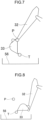
FIG. 8 is a side view of the arm and the bucket, and is a view illustrating a state where the opening surface of the bucket faces downward. - In the following, a preferred embodiment of the present invention will be described with reference to the drawings.
- A work machine according to an embodiment of the present invention automatically performs an operation of discharging a transport object held by a bucket. As illustrated in
FIG. 1 , which is a side view of awork machine 1, thework machine 1 is a machine that performs work with anattachment 30, and is, for example, a hydraulic excavator. Thework machine 1 has: amachine body 24 including alower travelling body 21 and anupper slewing body 22; theattachment 30; andcylinders 40. - The
lower travelling body 21 is a portion that causes thework machine 1 to travel, and includes, for example, a crawler. Theupper slewing body 22 is slewably attached to an upper part of thelower travelling body 21 via aslewing device 25. A cab (driver's cabin) 23 is located at a front part of theupper slewing body 22. - The
attachment 30 is attached to theupper slewing body 22 to be rotatable in an up-and-down direction. Theattachment 30 includes aboom 31, anarm 32, and abucket 33. Theboom 31 is attached to theupper slewing body 22 to be rotatable in an up-and-down direction (capable of rising and contracting). Thearm 32 is attached to theboom 31 to be rotatable in an up-and-down direction. Thebucket 33 is attached to thearm 32 so as to be rotatable in a front-and-rear direction. Thebucket 33 is a portion that performs work including excavation, leveling, and scooping of soil and sand (transport object). However, the transport object is not limited to soil and sand, and may be a stone or a waste (industrial waste or the like). - The
cylinders 40 can hydraulically move theattachment 30 rotationally. Thecylinders 40 are hydraulic telescopic cylinders. Thecylinders 40 include aboom cylinder 41, anarm cylinder 42, and abucket cylinder 43. - The
boom cylinder 41 rotationally moves theboom 31 with respect to theupper slewing body 22. Theboom cylinder 41 has a base end part rotatably attached to theupper slewing body 22. Theboom cylinder 41 has a leading end part rotatably attached to theboom 31. - The
arm cylinder 42 rotationally moves thearm 32 with respect to theboom 31. Thearm cylinder 42 has a base end part rotatably attached to theboom 31. Thearm cylinder 42 has a leading end part rotatably attached to thearm 32. - The
bucket cylinder 43 rotationally moves thebucket 33 with respect to thearm 32. Thebucket cylinder 43 has a base end part rotatably attached to thearm 32. Thebucket cylinder 43 has a leading end part rotatably attached to alink member 34 rotatably attached to thebucket 33. - The
work machine 1 further includes anangle sensor 52, andinclination angle sensors 60. - The
angle sensor 52 detects a slewing angle of theupper slewing body 22 with respect to thelower travelling body 21. Theangle sensor 52 is, for example, an encoder, a resolver, or a gyro sensor. In the present embodiment, the slewing angle of theupper slewing body 22 when a front side of theupper slewing body 22 coincides with a front side of thelower travelling body 21 is 0°. - The
inclination angle sensors 60 detect an orientation of theattachment 30. Theinclination angle sensors 60 includes a boominclination angle sensor 61, an arminclination angle sensor 62, and a bucketinclination angle sensor 63. - The boom
inclination angle sensor 61 is attached to theboom 31 and detects an attitude of theboom 31. The boominclination angle sensor 61 may be a sensor that acquires an inclination angle of theboom 31 with respect to the horizontal line, and may be, for example, an inclination (acceleration) sensor or the like. Note that the boominclination angle sensor 61 may be a rotation angle sensor that detects a rotation angle of a boom foot pin (a base end of the boom) or a stroke sensor that detects a stroke amount of theboom cylinder 41. - The arm
inclination angle sensor 62 is attached to thearm 32 to detect an orientation of thearm 32. The arminclination angle sensor 62 may be a sensor that acquires an inclination angle of thearm 32 with respect to the horizontal line, and may be, for example, an inclination (acceleration) sensor or the like. Note that the arminclination angle sensor 62 may be a rotation angle sensor that detects a rotation angle of an arm connection pin (a base end of the arm) or a stroke sensor that detects a stroke amount of thearm cylinder 42. - The bucket
inclination angle sensor 63 is attached to thelink member 34 to detect an orientation of thebucket 33. The bucketinclination angle sensor 63 may be a sensor that acquires an inclination angle of thebucket 33 with respect to the horizontal line, and may be, for example, an inclination (acceleration) sensor or the like. Note that the bucketinclination angle sensor 63 may be a rotation angle sensor that detects a rotation angle of a bucket connection pin (base end of the bucket) or a stroke sensor that detects a stroke amount of thebucket cylinder 43. - As illustrated in
FIG. 2 , which is a side view of thetransport vehicle 3, thetransport vehicle 3 is a vehicle having aloading bed 56, which is the loading target. Thetransport vehicle 3 is a vehicle for transporting soil and sand (load) loaded by thework machine 1, and may be a dump truck or a truck. - The
transport vehicle 3 includes amain body 55 and aloading bed 56. Themain body 55 can travel and supports theloading bed 56. Themain body 55 includes a driver'scabin 57. Theloading bed 56 is disposed on the rear side of thetransport vehicle 3 with respect to the driver'scabin 57. - Hereinafter, as for the directions related to the
transport vehicle 3, the side from the driver'scabin 57 toward theloading bed 56 is referred to as a "transport vehicle rear side", and a side from theloading bed 56 toward the driver'scabin 57 is referred to as a "transport vehicle front side". - The
loading bed 56 has no lid, and has, for example, a box shape. Theloading bed 56 includes afloor surface 56a, adrop tailgate surface 56b, side drop panel surfaces 56c on the right and left sides, and acab protector surface 56d. Thefloor surface 56a is a bottom surface (lower surface) of theloading bed 56. Thedrop tailgate surface 56b is a surface of theloading bed 56 on the transport vehicle rear side, and protrudes upward from a part of thefloor surface 56a on the transport vehicle rear side. The side drop panel surfaces 56c are right and left surfaces of theloading bed 56, and protrude upward from right and left end parts of thefloor surface 56a. Thecab protector surface 56d is a surface of theloading bed 56 on the front side of the transport vehicle, and protrudes upward from a part of thefloor surface 56a on the transport vehicle front side. Thecab protector surface 56d protrudes higher than the side drop panel surfaces 56c and protrudes higher than thedrop tailgate surface 56b. - The
loading bed 56 stores soil and sand (load). Theloading bed 56 may be movable with respect to themain body 55 or may be fixed to themain body 55. Note that the loading target on which thework machine 1 performs a loading work (soil discharging work) need not be theloading bed 56 of thetransport vehicle 3, and may be, for example, a container directly placed on the ground or the like. - As shown in
FIG. 1 , amobile terminal 5 is a terminal operated by a worker at a work site, and is, for example, a tablet terminal. Themobile terminal 5 is mutually communicable with thework machine 1. Note that themobile terminal 5 may be a smartphone or the like. - As shown in
FIG. 3 , which is circuit diagrams of thework machine 1 and themobile terminal 5, thework machine 1 includes acontroller 11, a work machineside communication device 12, and astorage 13. - The
controller 11 automatically controls thework machine 1. Thecontroller 11 causes thework machine 1 to automatically perform a series of operations from excavation of soil and sand to soil discharging. In other words, thework machine 1 is automatically operated. Specifically, thecontroller 11 automatically operates theslewing device 25 and theattachment 30 based on detection values by theangle sensor 52 and theinclination angle sensors 60. - The work machine
side communication device 12 is communicable with a mobile terminalside communication device 16 to be described later of themobile terminal 5. Thestorage 13 can store a target loading point to be described later. - The
mobile terminal 5 includes a mobileterminal side controller 15, the mobile terminalside communication device 16, adisplay 17, and atouch panel 18. - The mobile terminal
side communication device 16 can communicate with the work machineside communication device 12 of thework machine 1. The mobileterminal side controller 15 receives information on a position of the leading end of the arm 32 (a base end of the bucket 33) from thework machine 1 via the mobile terminalside communication device 16. - Here, as illustrated in
FIG. 4 , which is a top view of thework machine 1 and thetransport vehicle 3, a series of operations from excavation of soil and sand to soil discharging is performed in a state where thetransport vehicle 3 is disposed such that the longitudinal direction of thetransport vehicle 3 is along the slewing direction of theupper slewing body 22 of thework machine 1 and thetransport vehicle 3 is stopped. That is, after thebucket 33 scoops soil and sand from a soil-and-sand storage place 70, thecontroller 11 causes theupper slewing body 22 to slew so as to position thebucket 33 above theloading bed 56 of thetransport vehicle 3. Then, after soil is discharged into theloading bed 56, thecontroller 11 causes theupper slewing body 22 to slew in the direction opposite to the above direction so as to position thebucket 33 above the soil-and-sand storage place 70. Thecontroller 11 causes these operations to be automatically repeated. The soil-and-sand storage place 70 is a soil-and-sand pit or a soil-and-sand mound. - The
controller 11 of thework machine 1 sets a target loading point P above theloading bed 56. The target loading point P is a target position at which thework machine 1 performs loading work (soil discharging work) on thetransport vehicle 3. The loading work is work of discharging soil and sand held by thebucket 33 to theloading bed 56. The target loading point P is set by so-called teaching. - The teaching is performed as follows. First, the leading end of the arm 32 (the base end of the bucket 33) is disposed above the
loading bed 56 by a manual operation by an operator. When the operator carrying themobile terminal 5 checks the position of the leading end of thearm 32 at this time and determines that there is no problem, the operator operates thetouch panel 18 to establish the position. Information on the position is transmitted to thecontroller 11 of thework machine 1, and the position of the leading end of thearm 32 at this time is set as the target loading point P and stored in thestorage 13. - A plurality of target loading points P may be set in the longitudinal direction of the
loading bed 56 by teaching. The target loading point P is set at the central part of the width of theloading bed 56 in a direction orthogonal to each of the longitudinal direction and the vertical direction of the loading bed 56 (in other words, a transverse direction). - The
controller 11 controls the loading work based on the set target loading point P. At this time, after thecontroller 11 rotates thebucket 33 such that the opening surface of thebucket 33 becomes vertical at the target loading point P, thecontroller 11 drives theboom 31, thearm 32, and thebucket 33 such that the opening surface of thebucket 33 faces downward while maintaining the position, with respect to themachine body 24, of the leading end of thebucket 33 in the front-and-rear direction. - Specifically, as illustrated in
FIGS. 5 to 8 , which are side views of thearm 32 and thebucket 33, theboom 31, thearm 32, and thebucket 33 are driven. First, as illustrated inFIG. 5 , when the leading end of thearm 32 is disposed at the target loading point P in a state where thebucket 33 holds soil and sand, thecontroller 11 stops theboom 31, thearm 32, and thebucket 33 in that state. At this time, the opening surface of thebucket 33 is horizontal. - Next, as illustrated in
FIG. 6 , thecontroller 11 rotates thebucket 33 such that the opening surface of thebucket 33 becomes vertical. As a result, a part of the soil and sand held by thebucket 33 falls onto theloading bed 56. - Next, as illustrated in
FIGS. 7 and 8 , thecontroller 11 drives theboom 31, thearm 32, and thebucket 33 such that the opening surface of thebucket 33 faces downward while maintaining a position T, with respect to themachine body 24, of the leading end of thebucket 33 in the front-and-rear direction. Specifically, theboom 31 rotates and, at the same time, thearm 32 moves toward the upper slewing body 22 (an arm pulling operation is performed), so that the opening surface of thebucket 33 faces downward. With the rotation of theboom 31, soil and sand in thebucket 33 fall onto theloading bed 56. - As a result, as illustrated in
FIG. 8 , the opening surface of thebucket 33 is directed downward, and almost all of the soil and sand held by thebucket 33 falls onto theloading bed 56. - In the present embodiment, by directing the opening surface of the
bucket 33 downward while maintaining the position T of the leading end of thebucket 33 with respect to themachine body 24, the position at which the soil and sand are discharged can be kept substantially the same from the initial stage to the late stage of the rotation of thebucket 33. As a result, soil and sand can be loaded onto the fixed point of theloading bed 56. - In addition, by performing the operation of discharging soil and sand at the target loading point P set at the central part of the
loading bed 56 in the transverse direction of theloading bed 56, it is possible to suppress soil and sand from spilling from theloading bed 56. - On the other hand, it can be considered to drive the
boom 31, thearm 32, and thebucket 33 so as to maintain the position T of the leading end of thebucket 33 from the state where the opening surface of thebucket 33 is horizontal (the state illustrated inFIG. 5 ) to the state where the opening surface of thebucket 33 faces downward (the state illustrated inFIG. 8 ). However, in this case, because the leading end of thebucket 33 is closer to theupper slewing body 22 than the leading end of thearm 32 is, there is a possibility that, when thebucket 33 is rotated, thebucket 33 protrudes from theloading bed 56 in the region between theupper slewing body 22 and theloading bed 56 in plan view and soil and sand spill outside theloading bed 56. To address this issue, it can be considered to position the leading end of thebucket 33 at the target loading point P so that thebucket 33 does not protrude from theloading bed 56. However, in this case, there is a possibility that the leading end of thearm 32 is too distant from theupper slewing body 22 that the opening surface of thebucket 33 cannot be maintained to be horizontal due to the structure of theattachment 30. - In the present embodiment, the following operation makes it possible to maintain the opening surface of the
bucket 33 to be horizontal and to prevent thebucket 33 from protruding from theloading bed 56. The leading end of thearm 32 is positioned at the target loading point P in the state where the opening surface of thebucket 33 is horizontal, and after the opening surface of thebucket 33 is made vertical, thebucket 33 is rotated while maintaining the position T of the leading end of thebucket 33 with respect to themachine body 24. - As described above, in the
work machine 1 according to the present embodiment, after thebucket 33 is rotated such that the opening surface of thebucket 33 becomes vertical at the target loading point P, theboom 31, thearm 32, and thebucket 33 are driven such that the opening surface of thebucket 33 faces downward while the position T, with respect to themachine body 24, of the leading end of thebucket 33 in the front-and-rear direction is maintained. By directing the opening surface of thebucket 33 downward while maintaining the position of the leading end of thebucket 33 with respect to themachine body 24, the position where the soil and sand are discharged can be kept substantially the same from the initial stage to the late stage of the rotation of thebucket 33. As a result, soil and sand can be loaded onto the fixed point of theloading bed 56. - In addition, the target loading point P is set at the central part of the
loading bed 56 in the direction orthogonal to each of the longitudinal direction and the vertical direction of theloading bed 56. By performing the operation of discharging soil and sand at such a target loading point P, it is possible to suppress soil and sand from spilling from theloading bed 56. - Although the embodiment of the present invention has been described above, only a specific example has been described, and the present invention is not particularly limited to the embodiment; therefore, a specific configuration and the like can be modified in design as appropriate. In addition, the actions and effects described in the embodiment of the present invention merely recite the most suitable actions and effects resulting from the present invention, and the actions and effects according to the present invention are not limited to those described in the embodiment of the present invention.
Claims (2)
- A work machine comprising:a machine body;a boom attached to the machine body to be rotatable in an up-and-down direction;an arm attached to the boom to be rotatable in the up-and-down direction;a bucket attached to the arm to be rotatable in a front-and-rear direction; anda controller that causes the boom, the arm, and the bucket to automatically perform an operation of discharging a transport object held by the bucket by driving the boom, the arm, and the bucket, based on a target loading point set above a loading target,wherein after the controller causes the bucket to rotate such that an opening surface of the bucket becomes vertical at the target loading point, the controller drives the boom, the arm, and the bucket such that the opening surface of the bucket faces downward while maintaining a position, with respect to the machine body, of a leading end of the bucket in the front-and-rear direction.
- The work machine according to claim 1, wherein the target loading point is set at a central part of the loading target in a direction orthogonal to each of a longitudinal direction and a vertical direction of the loading target.
Applications Claiming Priority (2)
| Application Number | Priority Date | Filing Date | Title |
|---|---|---|---|
| JP2021064743A JP7707618B2 (en) | 2021-04-06 | 2021-04-06 | Work Machine |
| PCT/JP2022/009850 WO2022215413A1 (en) | 2021-04-06 | 2022-03-08 | Work machine |
Publications (3)
| Publication Number | Publication Date |
|---|---|
| EP4290016A1 true EP4290016A1 (en) | 2023-12-13 |
| EP4290016A4 EP4290016A4 (en) | 2024-08-21 |
| EP4290016B1 EP4290016B1 (en) | 2025-05-21 |
Family
ID=83546350
Family Applications (1)
| Application Number | Title | Priority Date | Filing Date |
|---|---|---|---|
| EP22784398.4A Active EP4290016B1 (en) | 2021-04-06 | 2022-03-08 | Work machine |
Country Status (5)
| Country | Link |
|---|---|
| US (1) | US12577752B2 (en) |
| EP (1) | EP4290016B1 (en) |
| JP (1) | JP7707618B2 (en) |
| CN (1) | CN116917579A (en) |
| WO (1) | WO2022215413A1 (en) |
Family Cites Families (18)
| Publication number | Priority date | Publication date | Assignee | Title |
|---|---|---|---|---|
| JPS55119838A (en) * | 1979-03-09 | 1980-09-13 | Sanyo Kiki Kk | Hydraulic control circuit in loader |
| US4753568A (en) | 1985-12-27 | 1988-06-28 | Westendorf Mfg. Co., Inc. | Material handling attachment for a tractor having a multiple-point hitch assembly |
| JPH0639794B2 (en) * | 1988-08-08 | 1994-05-25 | 住友建機株式会社 | Hydraulic excavator automatic operation pattern selection method |
| JP2922726B2 (en) | 1992-07-01 | 1999-07-26 | 株式会社フジタ | Excavator bucket guidance system |
| JPH1018339A (en) * | 1996-07-04 | 1998-01-20 | Komatsu Ltd | Arm position control method for construction machine and control device therefor |
| JP5358850B2 (en) | 2009-03-26 | 2013-12-04 | 株式会社小松製作所 | Method for determining cause of sensor failure in work vehicle |
| JP2012036645A (en) | 2010-08-06 | 2012-02-23 | Ohbayashi Corp | Loading amount management system and loading amount management method |
| JPWO2017010212A1 (en) | 2015-07-15 | 2018-02-15 | 株式会社日立製作所 | Work machine operation system and work machine having work machine operation system |
| JP6618072B2 (en) | 2015-08-28 | 2019-12-11 | キャタピラー エス エー アール エル | Work machine |
| CN113107046B (en) | 2015-12-28 | 2022-09-13 | 住友建机株式会社 | Shovel, shovel system, shovel control device, and shovel control method |
| CN111479967A (en) | 2017-12-15 | 2020-07-31 | 格特(私人)有限公司 | rear dump bucket loader |
| JP7383599B2 (en) | 2018-03-26 | 2023-11-20 | 住友建機株式会社 | excavator |
| JP7204366B2 (en) | 2018-07-31 | 2023-01-16 | 株式会社小松製作所 | Systems and methods for controlling work machines |
| JP2021011694A (en) | 2019-07-04 | 2021-02-04 | 株式会社小松製作所 | Work machine and control method of work machine |
| WO2021006349A1 (en) | 2019-07-11 | 2021-01-14 | 住友重機械工業株式会社 | Excavator |
| JP7469127B2 (en) * | 2020-04-17 | 2024-04-16 | 株式会社小松製作所 | Control system and control method |
| US12305368B2 (en) * | 2020-07-22 | 2025-05-20 | Deere &Company | Mobile machine control system |
| JP7702753B1 (en) | 2024-02-02 | 2025-07-04 | 栄建築株式会社 | Load-bearing wall structure of wooden houses, load-bearing wall construction method and load-bearing wall panel |
-
2021
- 2021-04-06 JP JP2021064743A patent/JP7707618B2/en active Active
-
2022
- 2022-03-08 CN CN202280019023.XA patent/CN116917579A/en active Pending
- 2022-03-08 WO PCT/JP2022/009850 patent/WO2022215413A1/en not_active Ceased
- 2022-03-08 US US18/553,780 patent/US12577752B2/en active Active
- 2022-03-08 EP EP22784398.4A patent/EP4290016B1/en active Active
Also Published As
| Publication number | Publication date |
|---|---|
| US12577752B2 (en) | 2026-03-17 |
| US20240183123A1 (en) | 2024-06-06 |
| JP2022160163A (en) | 2022-10-19 |
| EP4290016A4 (en) | 2024-08-21 |
| WO2022215413A1 (en) | 2022-10-13 |
| JP7707618B2 (en) | 2025-07-15 |
| CN116917579A (en) | 2023-10-20 |
| EP4290016B1 (en) | 2025-05-21 |
Similar Documents
| Publication | Publication Date | Title |
|---|---|---|
| CN111771031B (en) | System and method for controlling work machine | |
| JP7276046B2 (en) | Operation teaching system for work machines | |
| EP3333325A1 (en) | Work vehicle | |
| JP7484630B2 (en) | Loading point determination system | |
| CN114174599B (en) | work vehicle | |
| CN110352278A (en) | The control method of Work machine and Work machine | |
| CN103362159A (en) | Boom and Bucket Handle Assemblies for Industrial Machinery | |
| WO2023074175A1 (en) | Work machine | |
| CN118202118A (en) | Load discharge system | |
| EP4290016B1 (en) | Work machine | |
| JP7673470B2 (en) | Work Point Determination System | |
| JP2025123500A (en) | Work Area Setting System | |
| CN117916429A (en) | Operating machinery | |
| KR20160032898A (en) | forklift | |
| CN119923504A (en) | Operating machinery | |
| JP7585702B2 (en) | Attachment target trajectory change system | |
| JP7354978B2 (en) | Attachment target trajectory change system | |
| JP7786041B2 (en) | Work machinery | |
| JP2023074041A (en) | Work machine | |
| JP7559691B2 (en) | Work Machine | |
| JP3646441B2 (en) | Transporter | |
| JP2024172373A (en) | Work Machine | |
| JP3065599B1 (en) | Control device for continuous unloader | |
| US12630998B2 (en) | Work vehicle | |
| EP4502280A1 (en) | Work machine |
Legal Events
| Date | Code | Title | Description |
|---|---|---|---|
| STAA | Information on the status of an ep patent application or granted ep patent |
Free format text: STATUS: THE INTERNATIONAL PUBLICATION HAS BEEN MADE |
|
| PUAI | Public reference made under article 153(3) epc to a published international application that has entered the european phase |
Free format text: ORIGINAL CODE: 0009012 |
|
| STAA | Information on the status of an ep patent application or granted ep patent |
Free format text: STATUS: REQUEST FOR EXAMINATION WAS MADE |
|
| 17P | Request for examination filed |
Effective date: 20230906 |
|
| AK | Designated contracting states |
Kind code of ref document: A1 Designated state(s): AL AT BE BG CH CY CZ DE DK EE ES FI FR GB GR HR HU IE IS IT LI LT LU LV MC MK MT NL NO PL PT RO RS SE SI SK SM TR |
|
| DAV | Request for validation of the european patent (deleted) | ||
| DAX | Request for extension of the european patent (deleted) | ||
| A4 | Supplementary search report drawn up and despatched |
Effective date: 20240724 |
|
| RIC1 | Information provided on ipc code assigned before grant |
Ipc: E02F 9/26 20060101ALI20240718BHEP Ipc: E02F 9/20 20060101ALI20240718BHEP Ipc: E02F 3/43 20060101AFI20240718BHEP |
|
| GRAP | Despatch of communication of intention to grant a patent |
Free format text: ORIGINAL CODE: EPIDOSNIGR1 |
|
| STAA | Information on the status of an ep patent application or granted ep patent |
Free format text: STATUS: GRANT OF PATENT IS INTENDED |
|
| INTG | Intention to grant announced |
Effective date: 20250127 |
|
| GRAS | Grant fee paid |
Free format text: ORIGINAL CODE: EPIDOSNIGR3 |
|
| GRAA | (expected) grant |
Free format text: ORIGINAL CODE: 0009210 |
|
| STAA | Information on the status of an ep patent application or granted ep patent |
Free format text: STATUS: THE PATENT HAS BEEN GRANTED |
|
| AK | Designated contracting states |
Kind code of ref document: B1 Designated state(s): AL AT BE BG CH CY CZ DE DK EE ES FI FR GB GR HR HU IE IS IT LI LT LU LV MC MK MT NL NO PL PT RO RS SE SI SK SM TR |
|
| REG | Reference to a national code |
Ref country code: GB Ref legal event code: FG4D |
|
| REG | Reference to a national code |
Ref country code: CH Ref legal event code: EP |
|
| REG | Reference to a national code |
Ref country code: IE Ref legal event code: FG4D Ref country code: DE Ref legal event code: R096 Ref document number: 602022015031 Country of ref document: DE |
|
| REG | Reference to a national code |
Ref country code: NL Ref legal event code: MP Effective date: 20250521 |
|
| PG25 | Lapsed in a contracting state [announced via postgrant information from national office to epo] |
Ref country code: FI Free format text: LAPSE BECAUSE OF FAILURE TO SUBMIT A TRANSLATION OF THE DESCRIPTION OR TO PAY THE FEE WITHIN THE PRESCRIBED TIME-LIMIT Effective date: 20250521 Ref country code: ES Free format text: LAPSE BECAUSE OF FAILURE TO SUBMIT A TRANSLATION OF THE DESCRIPTION OR TO PAY THE FEE WITHIN THE PRESCRIBED TIME-LIMIT Effective date: 20250521 Ref country code: PT Free format text: LAPSE BECAUSE OF FAILURE TO SUBMIT A TRANSLATION OF THE DESCRIPTION OR TO PAY THE FEE WITHIN THE PRESCRIBED TIME-LIMIT Effective date: 20250922 |
|
| REG | Reference to a national code |
Ref country code: LT Ref legal event code: MG9D |
|
| PG25 | Lapsed in a contracting state [announced via postgrant information from national office to epo] |
Ref country code: GR Free format text: LAPSE BECAUSE OF FAILURE TO SUBMIT A TRANSLATION OF THE DESCRIPTION OR TO PAY THE FEE WITHIN THE PRESCRIBED TIME-LIMIT Effective date: 20250822 Ref country code: NO Free format text: LAPSE BECAUSE OF FAILURE TO SUBMIT A TRANSLATION OF THE DESCRIPTION OR TO PAY THE FEE WITHIN THE PRESCRIBED TIME-LIMIT Effective date: 20250821 |
|
| PG25 | Lapsed in a contracting state [announced via postgrant information from national office to epo] |
Ref country code: PL Free format text: LAPSE BECAUSE OF FAILURE TO SUBMIT A TRANSLATION OF THE DESCRIPTION OR TO PAY THE FEE WITHIN THE PRESCRIBED TIME-LIMIT Effective date: 20250521 Ref country code: NL Free format text: LAPSE BECAUSE OF FAILURE TO SUBMIT A TRANSLATION OF THE DESCRIPTION OR TO PAY THE FEE WITHIN THE PRESCRIBED TIME-LIMIT Effective date: 20250521 |
|
| PG25 | Lapsed in a contracting state [announced via postgrant information from national office to epo] |
Ref country code: BG Free format text: LAPSE BECAUSE OF FAILURE TO SUBMIT A TRANSLATION OF THE DESCRIPTION OR TO PAY THE FEE WITHIN THE PRESCRIBED TIME-LIMIT Effective date: 20250521 |
|
| PG25 | Lapsed in a contracting state [announced via postgrant information from national office to epo] |
Ref country code: HR Free format text: LAPSE BECAUSE OF FAILURE TO SUBMIT A TRANSLATION OF THE DESCRIPTION OR TO PAY THE FEE WITHIN THE PRESCRIBED TIME-LIMIT Effective date: 20250521 |
|
| PG25 | Lapsed in a contracting state [announced via postgrant information from national office to epo] |
Ref country code: RS Free format text: LAPSE BECAUSE OF FAILURE TO SUBMIT A TRANSLATION OF THE DESCRIPTION OR TO PAY THE FEE WITHIN THE PRESCRIBED TIME-LIMIT Effective date: 20250821 |
|
| PG25 | Lapsed in a contracting state [announced via postgrant information from national office to epo] |
Ref country code: IS Free format text: LAPSE BECAUSE OF FAILURE TO SUBMIT A TRANSLATION OF THE DESCRIPTION OR TO PAY THE FEE WITHIN THE PRESCRIBED TIME-LIMIT Effective date: 20250921 |
|
| PG25 | Lapsed in a contracting state [announced via postgrant information from national office to epo] |
Ref country code: LV Free format text: LAPSE BECAUSE OF FAILURE TO SUBMIT A TRANSLATION OF THE DESCRIPTION OR TO PAY THE FEE WITHIN THE PRESCRIBED TIME-LIMIT Effective date: 20250521 |
|
| REG | Reference to a national code |
Ref country code: AT Ref legal event code: MK05 Ref document number: 1796854 Country of ref document: AT Kind code of ref document: T Effective date: 20250521 |
|
| PG25 | Lapsed in a contracting state [announced via postgrant information from national office to epo] |
Ref country code: AT Free format text: LAPSE BECAUSE OF FAILURE TO SUBMIT A TRANSLATION OF THE DESCRIPTION OR TO PAY THE FEE WITHIN THE PRESCRIBED TIME-LIMIT Effective date: 20250521 Ref country code: SM Free format text: LAPSE BECAUSE OF FAILURE TO SUBMIT A TRANSLATION OF THE DESCRIPTION OR TO PAY THE FEE WITHIN THE PRESCRIBED TIME-LIMIT Effective date: 20250521 Ref country code: DK Free format text: LAPSE BECAUSE OF FAILURE TO SUBMIT A TRANSLATION OF THE DESCRIPTION OR TO PAY THE FEE WITHIN THE PRESCRIBED TIME-LIMIT Effective date: 20250521 |
|
| PG25 | Lapsed in a contracting state [announced via postgrant information from national office to epo] |
Ref country code: CZ Free format text: LAPSE BECAUSE OF FAILURE TO SUBMIT A TRANSLATION OF THE DESCRIPTION OR TO PAY THE FEE WITHIN THE PRESCRIBED TIME-LIMIT Effective date: 20250521 |
|
| PG25 | Lapsed in a contracting state [announced via postgrant information from national office to epo] |
Ref country code: EE Free format text: LAPSE BECAUSE OF FAILURE TO SUBMIT A TRANSLATION OF THE DESCRIPTION OR TO PAY THE FEE WITHIN THE PRESCRIBED TIME-LIMIT Effective date: 20250521 |
|
| PG25 | Lapsed in a contracting state [announced via postgrant information from national office to epo] |
Ref country code: SK Free format text: LAPSE BECAUSE OF FAILURE TO SUBMIT A TRANSLATION OF THE DESCRIPTION OR TO PAY THE FEE WITHIN THE PRESCRIBED TIME-LIMIT Effective date: 20250521 |
|
| PG25 | Lapsed in a contracting state [announced via postgrant information from national office to epo] |
Ref country code: IT Free format text: LAPSE BECAUSE OF FAILURE TO SUBMIT A TRANSLATION OF THE DESCRIPTION OR TO PAY THE FEE WITHIN THE PRESCRIBED TIME-LIMIT Effective date: 20250521 |
|
| REG | Reference to a national code |
Ref country code: DE Ref legal event code: R097 Ref document number: 602022015031 Country of ref document: DE |
|
| PLBE | No opposition filed within time limit |
Free format text: ORIGINAL CODE: 0009261 |
|
| STAA | Information on the status of an ep patent application or granted ep patent |
Free format text: STATUS: NO OPPOSITION FILED WITHIN TIME LIMIT |
|
| REG | Reference to a national code |
Ref country code: CH Ref legal event code: L10 Free format text: ST27 STATUS EVENT CODE: U-0-0-L10-L00 (AS PROVIDED BY THE NATIONAL OFFICE) Effective date: 20260402 |
|
| PGFP | Annual fee paid to national office [announced via postgrant information from national office to epo] |
Ref country code: GB Payment date: 20260202 Year of fee payment: 5 |
|
| PGFP | Annual fee paid to national office [announced via postgrant information from national office to epo] |
Ref country code: DE Payment date: 20260128 Year of fee payment: 5 |
|
| PGFP | Annual fee paid to national office [announced via postgrant information from national office to epo] |
Ref country code: FR Payment date: 20260209 Year of fee payment: 5 |
|
| 26N | No opposition filed |
Effective date: 20260224 |