EP4289660A1 - Control system for electric work vehicle - Google Patents
Control system for electric work vehicle Download PDFInfo
- Publication number
- EP4289660A1 EP4289660A1 EP23175375.7A EP23175375A EP4289660A1 EP 4289660 A1 EP4289660 A1 EP 4289660A1 EP 23175375 A EP23175375 A EP 23175375A EP 4289660 A1 EP4289660 A1 EP 4289660A1
- Authority
- EP
- European Patent Office
- Prior art keywords
- control device
- battery
- start switch
- switch
- vehicle
- Prior art date
- Legal status (The legal status is an assumption and is not a legal conclusion. Google has not performed a legal analysis and makes no representation as to the accuracy of the status listed.)
- Pending
Links
- 230000005856 abnormality Effects 0.000 claims description 3
- 230000005540 biological transmission Effects 0.000 description 14
- 238000010586 diagram Methods 0.000 description 12
- 229910052751 metal Inorganic materials 0.000 description 10
- 239000002184 metal Substances 0.000 description 10
- 238000001514 detection method Methods 0.000 description 9
- 238000000034 method Methods 0.000 description 8
- 230000000881 depressing effect Effects 0.000 description 7
- XEEYBQQBJWHFJM-UHFFFAOYSA-N Iron Chemical compound [Fe] XEEYBQQBJWHFJM-UHFFFAOYSA-N 0.000 description 6
- 230000007246 mechanism Effects 0.000 description 6
- 230000004044 response Effects 0.000 description 6
- 230000001186 cumulative effect Effects 0.000 description 5
- 230000000149 penetrating effect Effects 0.000 description 5
- 238000003825 pressing Methods 0.000 description 5
- 229910000838 Al alloy Inorganic materials 0.000 description 4
- 230000009471 action Effects 0.000 description 4
- 230000006870 function Effects 0.000 description 4
- 238000012423 maintenance Methods 0.000 description 4
- 229910000831 Steel Inorganic materials 0.000 description 3
- 230000000994 depressogenic effect Effects 0.000 description 3
- 229910052742 iron Inorganic materials 0.000 description 3
- 239000010959 steel Substances 0.000 description 3
- 238000012790 confirmation Methods 0.000 description 2
- 230000002950 deficient Effects 0.000 description 2
- 230000017525 heat dissipation Effects 0.000 description 2
- 230000006872 improvement Effects 0.000 description 2
- 230000009467 reduction Effects 0.000 description 2
- 238000009412 basement excavation Methods 0.000 description 1
- 230000008859 change Effects 0.000 description 1
- 238000005520 cutting process Methods 0.000 description 1
- 230000000694 effects Effects 0.000 description 1
- 230000002349 favourable effect Effects 0.000 description 1
- 238000007689 inspection Methods 0.000 description 1
- 238000009434 installation Methods 0.000 description 1
- 230000007257 malfunction Effects 0.000 description 1
- 238000004519 manufacturing process Methods 0.000 description 1
- 230000007935 neutral effect Effects 0.000 description 1
- 238000010079 rubber tapping Methods 0.000 description 1
- 238000003860 storage Methods 0.000 description 1
- 239000000725 suspension Substances 0.000 description 1
- 238000009423 ventilation Methods 0.000 description 1
Images



Classifications
-
- B—PERFORMING OPERATIONS; TRANSPORTING
- B60—VEHICLES IN GENERAL
- B60L—PROPULSION OF ELECTRICALLY-PROPELLED VEHICLES; SUPPLYING ELECTRIC POWER FOR AUXILIARY EQUIPMENT OF ELECTRICALLY-PROPELLED VEHICLES; ELECTRODYNAMIC BRAKE SYSTEMS FOR VEHICLES IN GENERAL; MAGNETIC SUSPENSION OR LEVITATION FOR VEHICLES; MONITORING OPERATING VARIABLES OF ELECTRICALLY-PROPELLED VEHICLES; ELECTRIC SAFETY DEVICES FOR ELECTRICALLY-PROPELLED VEHICLES
- B60L53/00—Methods of charging batteries, specially adapted for electric vehicles; Charging stations or on-board charging equipment therefor; Exchange of energy storage elements in electric vehicles
- B60L53/60—Monitoring or controlling charging stations
- B60L53/62—Monitoring or controlling charging stations in response to charging parameters, e.g. current, voltage or electrical charge
-
- B—PERFORMING OPERATIONS; TRANSPORTING
- B60—VEHICLES IN GENERAL
- B60L—PROPULSION OF ELECTRICALLY-PROPELLED VEHICLES; SUPPLYING ELECTRIC POWER FOR AUXILIARY EQUIPMENT OF ELECTRICALLY-PROPELLED VEHICLES; ELECTRODYNAMIC BRAKE SYSTEMS FOR VEHICLES IN GENERAL; MAGNETIC SUSPENSION OR LEVITATION FOR VEHICLES; MONITORING OPERATING VARIABLES OF ELECTRICALLY-PROPELLED VEHICLES; ELECTRIC SAFETY DEVICES FOR ELECTRICALLY-PROPELLED VEHICLES
- B60L58/00—Methods or circuit arrangements for monitoring or controlling batteries or fuel cells, specially adapted for electric vehicles
- B60L58/10—Methods or circuit arrangements for monitoring or controlling batteries or fuel cells, specially adapted for electric vehicles for monitoring or controlling batteries
-
- B—PERFORMING OPERATIONS; TRANSPORTING
- B60—VEHICLES IN GENERAL
- B60L—PROPULSION OF ELECTRICALLY-PROPELLED VEHICLES; SUPPLYING ELECTRIC POWER FOR AUXILIARY EQUIPMENT OF ELECTRICALLY-PROPELLED VEHICLES; ELECTRODYNAMIC BRAKE SYSTEMS FOR VEHICLES IN GENERAL; MAGNETIC SUSPENSION OR LEVITATION FOR VEHICLES; MONITORING OPERATING VARIABLES OF ELECTRICALLY-PROPELLED VEHICLES; ELECTRIC SAFETY DEVICES FOR ELECTRICALLY-PROPELLED VEHICLES
- B60L50/00—Electric propulsion with power supplied within the vehicle
- B60L50/50—Electric propulsion with power supplied within the vehicle using propulsion power supplied by batteries or fuel cells
- B60L50/51—Electric propulsion with power supplied within the vehicle using propulsion power supplied by batteries or fuel cells characterised by AC-motors
-
- B—PERFORMING OPERATIONS; TRANSPORTING
- B60—VEHICLES IN GENERAL
- B60L—PROPULSION OF ELECTRICALLY-PROPELLED VEHICLES; SUPPLYING ELECTRIC POWER FOR AUXILIARY EQUIPMENT OF ELECTRICALLY-PROPELLED VEHICLES; ELECTRODYNAMIC BRAKE SYSTEMS FOR VEHICLES IN GENERAL; MAGNETIC SUSPENSION OR LEVITATION FOR VEHICLES; MONITORING OPERATING VARIABLES OF ELECTRICALLY-PROPELLED VEHICLES; ELECTRIC SAFETY DEVICES FOR ELECTRICALLY-PROPELLED VEHICLES
- B60L53/00—Methods of charging batteries, specially adapted for electric vehicles; Charging stations or on-board charging equipment therefor; Exchange of energy storage elements in electric vehicles
- B60L53/20—Methods of charging batteries, specially adapted for electric vehicles; Charging stations or on-board charging equipment therefor; Exchange of energy storage elements in electric vehicles characterised by converters located in the vehicle
- B60L53/22—Constructional details or arrangements of charging converters specially adapted for charging electric vehicles
-
- B—PERFORMING OPERATIONS; TRANSPORTING
- B60—VEHICLES IN GENERAL
- B60L—PROPULSION OF ELECTRICALLY-PROPELLED VEHICLES; SUPPLYING ELECTRIC POWER FOR AUXILIARY EQUIPMENT OF ELECTRICALLY-PROPELLED VEHICLES; ELECTRODYNAMIC BRAKE SYSTEMS FOR VEHICLES IN GENERAL; MAGNETIC SUSPENSION OR LEVITATION FOR VEHICLES; MONITORING OPERATING VARIABLES OF ELECTRICALLY-PROPELLED VEHICLES; ELECTRIC SAFETY DEVICES FOR ELECTRICALLY-PROPELLED VEHICLES
- B60L58/00—Methods or circuit arrangements for monitoring or controlling batteries or fuel cells, specially adapted for electric vehicles
- B60L58/10—Methods or circuit arrangements for monitoring or controlling batteries or fuel cells, specially adapted for electric vehicles for monitoring or controlling batteries
- B60L58/18—Methods or circuit arrangements for monitoring or controlling batteries or fuel cells, specially adapted for electric vehicles for monitoring or controlling batteries of two or more battery modules
- B60L58/20—Methods or circuit arrangements for monitoring or controlling batteries or fuel cells, specially adapted for electric vehicles for monitoring or controlling batteries of two or more battery modules having different nominal voltages
-
- B—PERFORMING OPERATIONS; TRANSPORTING
- B60—VEHICLES IN GENERAL
- B60L—PROPULSION OF ELECTRICALLY-PROPELLED VEHICLES; SUPPLYING ELECTRIC POWER FOR AUXILIARY EQUIPMENT OF ELECTRICALLY-PROPELLED VEHICLES; ELECTRODYNAMIC BRAKE SYSTEMS FOR VEHICLES IN GENERAL; MAGNETIC SUSPENSION OR LEVITATION FOR VEHICLES; MONITORING OPERATING VARIABLES OF ELECTRICALLY-PROPELLED VEHICLES; ELECTRIC SAFETY DEVICES FOR ELECTRICALLY-PROPELLED VEHICLES
- B60L2200/00—Type of vehicles
- B60L2200/40—Working vehicles
-
- B—PERFORMING OPERATIONS; TRANSPORTING
- B60—VEHICLES IN GENERAL
- B60L—PROPULSION OF ELECTRICALLY-PROPELLED VEHICLES; SUPPLYING ELECTRIC POWER FOR AUXILIARY EQUIPMENT OF ELECTRICALLY-PROPELLED VEHICLES; ELECTRODYNAMIC BRAKE SYSTEMS FOR VEHICLES IN GENERAL; MAGNETIC SUSPENSION OR LEVITATION FOR VEHICLES; MONITORING OPERATING VARIABLES OF ELECTRICALLY-PROPELLED VEHICLES; ELECTRIC SAFETY DEVICES FOR ELECTRICALLY-PROPELLED VEHICLES
- B60L2210/00—Converter types
- B60L2210/10—DC to DC converters
-
- B—PERFORMING OPERATIONS; TRANSPORTING
- B60—VEHICLES IN GENERAL
- B60L—PROPULSION OF ELECTRICALLY-PROPELLED VEHICLES; SUPPLYING ELECTRIC POWER FOR AUXILIARY EQUIPMENT OF ELECTRICALLY-PROPELLED VEHICLES; ELECTRODYNAMIC BRAKE SYSTEMS FOR VEHICLES IN GENERAL; MAGNETIC SUSPENSION OR LEVITATION FOR VEHICLES; MONITORING OPERATING VARIABLES OF ELECTRICALLY-PROPELLED VEHICLES; ELECTRIC SAFETY DEVICES FOR ELECTRICALLY-PROPELLED VEHICLES
- B60L2210/00—Converter types
- B60L2210/10—DC to DC converters
- B60L2210/12—Buck converters
-
- B—PERFORMING OPERATIONS; TRANSPORTING
- B60—VEHICLES IN GENERAL
- B60L—PROPULSION OF ELECTRICALLY-PROPELLED VEHICLES; SUPPLYING ELECTRIC POWER FOR AUXILIARY EQUIPMENT OF ELECTRICALLY-PROPELLED VEHICLES; ELECTRODYNAMIC BRAKE SYSTEMS FOR VEHICLES IN GENERAL; MAGNETIC SUSPENSION OR LEVITATION FOR VEHICLES; MONITORING OPERATING VARIABLES OF ELECTRICALLY-PROPELLED VEHICLES; ELECTRIC SAFETY DEVICES FOR ELECTRICALLY-PROPELLED VEHICLES
- B60L2250/00—Driver interactions
-
- Y—GENERAL TAGGING OF NEW TECHNOLOGICAL DEVELOPMENTS; GENERAL TAGGING OF CROSS-SECTIONAL TECHNOLOGIES SPANNING OVER SEVERAL SECTIONS OF THE IPC; TECHNICAL SUBJECTS COVERED BY FORMER USPC CROSS-REFERENCE ART COLLECTIONS [XRACs] AND DIGESTS
- Y02—TECHNOLOGIES OR APPLICATIONS FOR MITIGATION OR ADAPTATION AGAINST CLIMATE CHANGE
- Y02T—CLIMATE CHANGE MITIGATION TECHNOLOGIES RELATED TO TRANSPORTATION
- Y02T10/00—Road transport of goods or passengers
- Y02T10/60—Other road transportation technologies with climate change mitigation effect
- Y02T10/70—Energy storage systems for electromobility, e.g. batteries
-
- Y—GENERAL TAGGING OF NEW TECHNOLOGICAL DEVELOPMENTS; GENERAL TAGGING OF CROSS-SECTIONAL TECHNOLOGIES SPANNING OVER SEVERAL SECTIONS OF THE IPC; TECHNICAL SUBJECTS COVERED BY FORMER USPC CROSS-REFERENCE ART COLLECTIONS [XRACs] AND DIGESTS
- Y02—TECHNOLOGIES OR APPLICATIONS FOR MITIGATION OR ADAPTATION AGAINST CLIMATE CHANGE
- Y02T—CLIMATE CHANGE MITIGATION TECHNOLOGIES RELATED TO TRANSPORTATION
- Y02T10/00—Road transport of goods or passengers
- Y02T10/60—Other road transportation technologies with climate change mitigation effect
- Y02T10/7072—Electromobility specific charging systems or methods for batteries, ultracapacitors, supercapacitors or double-layer capacitors
-
- Y—GENERAL TAGGING OF NEW TECHNOLOGICAL DEVELOPMENTS; GENERAL TAGGING OF CROSS-SECTIONAL TECHNOLOGIES SPANNING OVER SEVERAL SECTIONS OF THE IPC; TECHNICAL SUBJECTS COVERED BY FORMER USPC CROSS-REFERENCE ART COLLECTIONS [XRACs] AND DIGESTS
- Y02—TECHNOLOGIES OR APPLICATIONS FOR MITIGATION OR ADAPTATION AGAINST CLIMATE CHANGE
- Y02T—CLIMATE CHANGE MITIGATION TECHNOLOGIES RELATED TO TRANSPORTATION
- Y02T90/00—Enabling technologies or technologies with a potential or indirect contribution to GHG emissions mitigation
- Y02T90/10—Technologies relating to charging of electric vehicles
- Y02T90/14—Plug-in electric vehicles
Definitions
- the present invention relates to a control system for electric work vehicles.
- a work vehicle including a work implement has been known.
- a lawn mowing vehicle (work vehicle) including a lawn mowing device as a work implement which is driven to perform lawn mowing works has been known.
- an electric work vehicle whose wheels are driven by a traveling motor, which is an electric motor, is also considered.
- Patent Document 1 describes an agricultural tractor (electric work vehicle) which can charge a battery mounted on the vehicle from an external power-feed facility and can supply power from the battery to an electric motor for driving the rear wheels (traveling motor).
- a power-supply state switch is provided at a position which covers a charging connection portion connecting an external connection portion of the external power-feed facility, and the switch can be removed from the covered position by operating a key member.
- Patent Document 1 Japanese Unexamined Patent Application Publication No. 2013-66290
- An object of the present invention is to enlarge the space for a size increase of the other components such as a high-voltage battery and to reduce a labor for battery replacement by eliminating the need for mounting a low-voltage battery in the control system of an electric work vehicle.
- a control system for an electric work vehicle is a control system for an electric work vehicle, including a battery, a traveling motor to which power is fed from a battery via a main switch, a control device which controls an ON/OFF state of the main switch, a DC-DC converter which steps down a voltage of the battery and outputs the voltage to the control device, and a first start switch which is interposed and connected between an output side of the DC-DC converter and the control device and capable of manual energization, in which a primary side of the main switch is connected to an input side of the DC-DC converter with a second start switch capable of manual energization interposed therebetween, a secondary side of the main switch is directly connected to the input side of the DC-DC converter, and the control device is configured to be started by an output voltage of the DC-DC converter by an operation of the second start switch to an energized position of the second start switch, and the control device turns on the main switch when the second start switch is operated to the energized position and the first start switch is
- the control system for an electric work vehicle since only a battery with a voltage higher than the voltage input to the control device needs to be mounted on a vehicle as a battery, mounting of a low-voltage battery on the vehicle becomes unnecessary.
- the control device executes the predetermined end processing after the operation of the first start switch to the shut-off position, it can turn off the switch and can stop the power feeding from the battery to the traveling motor and the control device.
- the system can be stopped safely without providing a low-voltage battery.
- a space for the size increase of the other components such as a high-voltage battery can be enlarged, and the labor for battery charging can be reduced.
- control system for the electric work vehicle it may be so configured that a working motor for driving the work implement to which power is fed from the battery via the main switch is provided, and when the first start switch is operated to the shut-off position, after executing the predetermined end processing including setting of target rotation numbers of rotation speeds of the traveling motor and the working motor to 0, the control device turns off the main switch and stops the power feeding to the traveling motor, the working motor, and the control device from the battery.
- the system of the vehicle can be stopped more safely by operating the first start switch to the shut-off position without providing a low-voltage battery.
- control system for the electric work vehicle it may be so configured that a charging port which can be connected to an external power-feed facility via a charger and is connected to the battery via the main switch is provided, and when the second start switch is operated to the energized position, the first start switch is off, and the charger is connected to the charging port, the control device turns on the main switch and feeds power to the battery and the control device maintains the ON state of the main switch even after the operation of the second start switch to the shut-off position.
- the charging operation can be performed while starting the control device and thus, a stable charging work of the battery can be performed easily.
- the first start switch is a two-position switch and the second start switch is a push switch in which the state operated to the energized position is not self-retained.
- control system for the electric work vehicle it may be so configured that, when the charger is connected to the charging port, if the charging is not started within a predetermined time from the operation of the second start switch to the energized position, the control device turns off the main switch as abnormality occurrence processing.
- control system for the electric work vehicle According to the control system for the electric work vehicle according to the present invention, mounting of a low-voltage battery becomes unnecessary, a space for a size increase of the other components such as a high-voltage battery can be enlarged, and a labor for the battery replacement can be reduced.
- an electric work vehicle is a lawn mowing vehicle
- the electric work vehicle is not limited to a lawn mowing vehicle but may be any other work vehicles including a work implement that performs one or more of a snow removal work, an excavation work, a civil engineering work, and an agricultural work.
- a case in which a work vehicle has a steering wheel as a travel instruction tool and uses an accelerator pedal provided on a front side of a seat as the travel instruction tool will be basically explained below, but this is only an example, and regarding at least an invention related to disposition of a junction box or an inverter, it may be so configured that the present invention is applied to a vehicle having two operation levers, left and right, as the travel instruction tool also serving as a turning instruction portion.
- the term travel in the travel instruction tool is used as a meaning excluding turning.
- Shapes, numbers, disposition relationships of components and the like which will be explained below are only examples for explanation and can be changed as appropriate to comply with specifications of the work vehicle. In the following, the same signs are given to similar elements in all of the drawings, and duplicated explanation will be omitted or simplified.
- FIGs. 1 to 8 illustrate an embodiment of the present invention.
- FIG. 1 is a schematic diagram illustrating an electric work vehicle 10 including a control system of an embodiment, viewed from one side in a left-right direction, which is a width direction and partially sectioned.
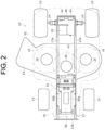
- FIG. 2 is a schematic diagram of an A-A section in FIG. 1 .
- FIG. 3 is a schematic diagram of a B-B section in FIG. 1 .
- the electric work vehicle 10 is referred to as the vehicle 10.
- the vehicle 10 is a passenger-type self-propelled lawn mowing vehicle suitable for lawn mowing.
- the vehicle 10 includes a vehicle-body frame 12, two front wheels 14, left and right, supported on the front side of the vehicle-body frame 12 and two rear wheels 16, left and right, supported on the rear side, a lawn mowing device 18, which is a work implement, a traveling motor 20 ( FIG. 2 ), which drives the rear wheels 16 among the front wheels 14 and the rear wheels 16, three deck motors 26, which are working motors, a steering handle 32, and an accelerator pedal (not shown).
- the vehicle 10 further includes a traveling inverter 42, three deck inverters 44, a control device (ECU) 46, which constitute a control portion 100 and a battery 90.
- Each of the traveling motor 20 and the deck motor 26 is an electric motor.
- the traveling inverter 42 corresponds to a first inverter
- the deck inverter 44 corresponds to a second inverter.
- the vehicle-body frame 12 is formed of metal such as steel into a beam structure or the like.
- the vehicle-body frame 12 includes two side frames 12a substantially along a front-back direction of the machine body at both left and right ends, a front-end connecting portion 12b that connects front ends of the two side frames 12a, and an inverter mounting member 48 that connects the rear ends.
- Each of the side frames 12a is formed by including a main-body plate portion along an up-down direction and the front-back direction and two lateral plate portions projecting outward in the left-right direction from both upper and lower end parts of the main-body plate portion, and an opening of the side frame 12a is directed toward a center in the left-right direction of the vehicle.
- the front-end connecting portion 12b has a plate shape projecting to the front end of the vehicle and extending in the left-right direction and has a function as a bumper.
- the inverter mounting member 48 will be described in more detail later.
- a driver's seat 51 On upper sides of the rear end parts of the two side frames 12a, a driver's seat 51, on which the driver as a user is seated, is fixed via the inverter mounting member 48 and a support member 52.
- the support member 52 is supported on the upper side of the left and right side frames 12a in the vehicle-body frame 12 and includes a front portion 52a on which the driver onboard the vehicle 10 places the driver's feet and a rear portion 52b that rises upward toward the rear and whose both left and right end parts on the rear side are fender portions covering the upper sides of the two rear wheels 16. That is, on the upper end part of the rear portion 52b of the support member 52, two shoulder portions project upward at intervals on both left and right sides, and the driver's seat 51 is fixed to a portion depressed downward between the two shoulder portions.
- a steering shaft 34 is rotatably supported by a steering column 36, and a steering handle 32 is fixed to the upper end of the steering shaft 34.
- the steering shaft 34 steers the two front wheels 14 by pushing and pulling the two front wheels 14, left and right, by the Ackermann type with rotation thereof.
- An accelerator pedal (not shown) is provided on the floor on a front right of the driver's seat 51.
- the accelerator pedal is a seesaw type with a substantially V-shaped section that can swing around an axis along the left-right direction of the vehicle.
- forward travel is instructed by depressing the front side, and the larger a depressing amount becomes, the higher a vehicle speed becomes in the forward travel.
- backward travel is instructed by depressing the rear side, and the larger the depressing amount becomes, the higher the vehicle speed becomes in the backward travel.
- the accelerator pedal is operated to set a moving direction of the vehicle by a depression side and an operation position of the depressing and to set a vehicle speed from zero to a predetermined value. It is configured such that, when the driver releases the driver's foot from the pedal tread, the accelerator pedal is maintained at a vehicle-speed zero position by a return spring, not shown, which is mechanically connected to the accelerator pedal.
- the depression side and the operation position of the accelerator pedal are detected by the accelerator pedal sensor 60 ( FIG. 5 ).
- the accelerator pedal sensor 60 corresponds to a traveling instruction sensor.
- a detection signal of the accelerator pedal sensor 60 is transmitted to the control device 46.
- the control device 46 controls a rotation direction and a rotation speed of the traveling motor 20 on the basis of the operation side and the operation position of the accelerator pedal.
- the accelerator pedal is not limited to a seesaw type but can be a two-pedal type with different pedals for a forward travel and a backward travel.
- the accelerator pedal may be a single pedal common to the forward and backward travels, and the vehicle may be provided with a forward/backward switching operation-tool for instructing switching between the forward and backward travels.
- the steering column 36 covers the lower side of the steering shaft 34.
- the steering column 36 includes two side plate portions 36a, left and right, that rise from the upper surface of the front portion 52a of the support member 52, and a rear-end plate portion 36b that connects the rear ends of the two side plate portions 36a and rises from the upper surface of the front portion 52a.
- the rear-end plate portion 36b is inclined upward to the rear.
- a steering panel 37 which is a plate portion having a substantially rectangular shape inclined upward to the front is provided.
- an upper-end plate portion 38 inclined to the lower side as it goes toward the front is provided.
- a charging port 39 capable of connecting a charging connector of a charging cable connected to an external power-feed facility is provided.
- the charging port 39 may be provided anywhere as long as it is in the vicinity of a junction box 71, which will be described later, such as the side plate portion 36a.
- a cylinder portion 40 protruding diagonally upward to the rear side from the center of the lower end part is provided on the steering panel 37.
- the upper end part of the steering shaft protrudes from the upper-end plate portion of the cylinder portion 40.
- an operation switch group 62 ( FIG. 4 ), described later, is provided on the steering panel 37.
- the traveling motor 20, together with a power transmission unit 22, is supported between the left and right rear wheels 16 on the lower side of the rear-end portion of the vehicle-body frame 12.
- a motor case of the traveling motor 20 is fixed to a unit case of the power transmission unit 22, whereby the power transmission unit 22 and the traveling motor 20 are integrated.
- a rotation shaft of the traveling motor 20 is disposed along the left-right direction.
- the traveling motor 20 is, for example, a 3-phase motor.
- the power transmission unit 22 includes a reduction gear mechanism and a differential mechanism in the unit case, reduces power of the traveling motor 20 and transmits the power to left and right axles 24 ( FIG. 2 ) connected to the left and right rear wheels 16.
- the traveling motor 20 and the power transmission unit 22 are disposed under the driver's seat 51.
- the traveling inverter 42 ( FIG. 3 ), described later, is also disposed under the driver's seat 51.
- the battery 90 is connected via the traveling inverter 42 and a main contactor 112 as a main switch installed in the junction box (J/B) 71, and power from the battery 90 is supplied to the traveling motor 20.
- the main contactor 112 is controlled by the control device 46 described later, whereby it switches electrical connection and disconnection between the battery 90 and the traveling inverter 42 (traveling motor 20).
- the main switch in the junction box (J/B) 71 may be a relay.
- the battery 90 is fixed to the upper side of the vehicle-body frame 12 in a state covered by the bonnet 91 on the front side of the driver's seat 51.
- the control device 46 controls a connection state of the main contactor 112 and the traveling inverter 42.
- the power of the traveling motor 20 is reduced by the reduction gear mechanism in the power transmission unit 22, and the reduced power is differentially transmitted to the left and right axles 24 by the differential mechanism to drive the left and right rear wheels 16 connected to the left and right axles 24. As a result, the vehicle 10 travels.
- the lawn mowing device 18 is supported on the lower side of an intermediate portion in the front-back direction of the vehicle-body frame 12. As a result, the lawn mowing device 18 is disposed between the front wheels 14 and the rear wheels 16 in the front-back direction.
- the lawn mowing device 18 includes three blades 18a that are rotary cutter disposed inside a mower deck 19, which is a cover.
- a circular trajectory of movement of a leading end of each of the lawn-mowing blades 18a is indicated by one-dotted chain lines a1, a2, and a3. Upper sides of the lawn-mowing blades 18a are covered by the mower deck 19.
- Each of the lawn-mowing blades 18a has a plurality of blade elements that rotate around an axis directed in the vertical direction (paper front-rear direction of FIG. 2 ). As a result, the blade elements rotate and can mow a lawn by cutting the lawn.
- a corresponding one of the deck motors 26 in the three deck motors 26 is connected.
- the battery 90 is connected via the deck inverter 44 ( FIG. 3 ) for the corresponding deck motor 26, and power is supplied from the battery 90 to the deck motor 26.
- Each of the deck motors 26 is a 3-phase motor, for example.
- the lawn mowing device may be configured to include, as a rotary lawn mowing tool, a lawn mowing reel in which a spiral blade is disposed on a rotation axis parallel to a ground surface, for example, having a function of mowing a lawn or the like, and driven by a deck motor.
- FIG. 4 is a diagram of the operation switch group 62 on the upper part of steering column 36 in the vehicle 10, viewed from above the vehicle.
- FIG. 5 is a circuit diagram of the control system 110 mounted on the vehicle 10.
- the operation switch group 62 is provided on the steering panel 37 of the steering column 36.
- the operation switch group 62 has a first start switch 63 and a second start switch 64 used to start the control system 110, a cruise switch 65, a working start switch 66, and an emergency stop switch 67.
- the first start switch 63 corresponds to an operation switch.
- the operation switch group 62 further has a load vehicle-speed control switch 68, a working speed select switch 69, and a backward-work permission switch 70.
- a circular indicator 72 is provided on an upper part of a center part in the left-right direction of the steering panel 37.
- the first start switch 63 has a knob portion and is a two-position type switch capable of a switching operation, that is, capable of an energization operation between on (energized position) and off (shut-off position) by being manually twisted.
- the second start switch 64 is a push switch capable of the switching operation between ON (energized position) and OFF (shut-off position), that is, capable of the energization operation, and is turned on by pressing down an operation portion 64a and is turned off by being returned upward by an internal spring force. Since the second start switch 64 does not have a function of self-retaining the ON state (energized position), the driver needs to manually keep the operation portion 64a pressed down when the driver wants to maintain the ON state.
- the second start switch 64 When the control system 110 is to be started during traveling, the second start switch 64 is turned on after the first start switch 63 is turned on. On the other hand, when the battery 90 is to be charged from an external charging facility, only the second start switch 64 is turned on and the first start switch 63 is not turned on. As shown in FIG. 5 , by turning on the second start switch 64, a voltage of the high-voltage battery 90, which holds a voltage for feeding power to various motors (such as 48 V) is input into the DC-DC converter 80, which is stepped down to the voltage for control signals (such as 12 V). An output-side terminal of the DC-DC converter 80 is connected to a power-supply terminal of the control device 46, and the output voltage generated by the DC-DC converter 80 starts the control device 46.
- control device 46 turns on the main contactor 112 connected between the battery 90 and the traveling motor 20, that is, it is closed, when the second start switch 64 is turned on, and the first start switch 63 is in the ON state, and even after the second start switch 64 is turned off, the ON state of the main contactor 112 is maintained, the secondary side of the main contactor 112 is brought into a power-feed state, and the high-voltage power-feed to the input port of the DC-DC converter 80 continues.
- the battery 90 provided in the vehicle can be only a high-voltage battery such as 48 V, which eliminates the need to provide a low-voltage battery such as 12 V in the bonnet for starting the control device 46 other than the high-voltage battery, and the limited space in the bonnet can be used for increasing a capacity of the battery 90. This will be explained in more detail later.
- the cruise switch 65 is provided to instruct execution of a cruise mode by the turning-on operation.
- the cruise mode is such a mode that the vehicle speed set at the accelerator pedal position when the cruise switch 65 is turned on is stored, and the rotation speed of the traveling motor 20 is controlled so that the traveling of the vehicle at that vehicle speed is maintained without operating the accelerator pedal.
- the working start switch 66 is a push-type switch provided to instruct switching between start and stop of the deck motor 26.
- the working start switch 66 is turned off and locked by pressing-down of the operation portion from the ON state.
- By twisting the operation portion in a predetermined direction while giving a force in a pressing-down direction from the OFF state the state is switched to the ON state and is locked.
- the operation portion returns to the OFF position by the internal spring force, resulting in the OFF state.
- the lawn mowing device 18 needs to be turned off in an emergency, it can be quickly switched from the ON state to the OFF state only by a simple pressing-down action of the operation portion, which leads to improvement of safety of the vehicle.
- the emergency stop switch 67 is provided for emergency stop of both the traveling motor 20 and the deck motor 26 by the pressing-down operation, which is the ON operation.
- the configuration of the emergency stop switch 67 is similar to that of the working start switch 66, except that the ON position and the OFF position of the emergency stop switch 67 are opposite to the ON position and the OFF position of the working start switch 66.
- the load vehicle-speed control switch 68 is a rocker-type switch and is provided to switch between an input for the load vehicle-speed control, that is, an execution state and shut-off, that is, a deactivated state.
- the load vehicle-speed control controls the traveling motor 20 so that the vehicle speed is automatically controlled in accordance with the load of the deck motor 26. For example, if a high load of the deck motor 26 is detected, the traveling motor 20 is controlled to reduce the vehicle speed in accordance with the detected load. On the other hand, if a low load of the deck motor 26 is detected, the traveling motor 20 is controlled to increase the vehicle speed in accordance with the detected load.
- the working speed select switch 69 is also a rocker-type switch and is provided to switch the speed of the deck motor 26 in two stages, that is, a predetermined speed on a high speed side and a predetermined speed on a low speed side.
- the backward-work permission switch 70 is provided to switch between an input for the backward work permission, that is, permitting the backward work to drive the lawn mowing device 18 while traveling backward and shut-off, that is, prohibiting the backward work. If the prohibition of the backward work is instructed, the control device 46 forcibly stops the drive of the lawn mowing device 18 during the backward travel of the vehicle by switching to the shut-off by operating the backward-work permission switch 70. If the permission of the backward work is instructed, the control device 46 invalidates the forced stop of the lawn mowing device 18 during the backward travel of the vehicle by switching to the input by operating the backward-work permission switch 70. As a result, the driver can perform the work while moving backward in a state where a safe situation is confirmed, whereby work efficiency can be improved.
- the indicator 72 has a remaining-charge display portion 73 and a cumulative start-time display portion 74.
- the remaining-charge display portion 73 indicates an allowable lower limit and an allowable upper limit of the residual charge of the battery 90 by E and F, respectively, and indicates that the residual charge is proper by lighting display located between E and F. In addition, as the lighting display gets closer to E, the driver can recognize that a traveling distance to insufficient charge is short.
- the cumulative start-time display portion 74 displays the cumulative start time of the vehicle after the shipment of the vehicle 10 from a manufacturing factory.
- a plurality of lamps 75 that display the system start or that a traveling action is capable by lighting up are also provided.
- the charging port 39 in a charging start state where an opening is exposed is shown, but in a case other than the charging, the charging port 39 is detachably covered by a lid that can be closed liquid-tightly.
- the control system 110 includes the aforementioned operation switch group 62, the accelerator pedal sensor 60, the brake pedal sensor 76, and the seat sensor 77.
- the control system 110 further includes the traveling motor 20 and the traveling inverter 42, the three deck motors 26 and the deck inverter 44, the battery 90, the charging port 39, the DC-DC converter 80, and the control device 46.
- a switching signal or a detection signal is input from the operation switch group 62, the accelerator pedal sensor 60, the brake pedal sensor 76, and the seat sensor 77.
- the second start switch 64 is interposed in a connection line on the primary side.
- the input side of the DC-DC converter 80 is directly connected.
- a power-supply terminal of the control device 46 is connected.
- the first start switch 63 is interposed and connected between the output-side terminal of the DC-DC converter 80 and the input terminal of the control device 46.
- the DC-DC converter 80 steps down the voltage input from the battery 90 via the second start switch 64 or the main contactor 112 to 12 V and outputs the voltage to a power-supply port of the control device 46 as indicated by arrows ⁇ 1 and ⁇ 2 in FIG. 5 .
- FIG. 5 only the first start switch 63, the second start switch 64, the cruise switch 65, and the working start switch 66 are shown among the operation switch group 62, but switching signals of the other switches in the operation switch group 62 are also input to the control device 46.
- the second start switch 64 inputs the high voltage from the battery 90 to the DC-DC converter 80 by its ON (to the energized position) operation, even in the OFF state (power-feeding stopped) state of the main contactor 112, and by causing the low voltage output from the DC-DC converter 80 to be input into the power-supply terminal of the control device 46, the control device 46 is started by the output voltage.
- the traveling inverter 42 as well as the deck inverter 44 and the traveling motor 20 as well as the deck motor 26 are shown as one element, respectively, but actually, the traveling inverter 42 and the three deck inverters 44 are connected in parallel on the power output side of junction box 71, and the traveling motor 20 and the deck motor 26 are connected to the traveling inverter 42 and the deck inverter 44, respectively.
- the brake pedal sensor 76 detects that the brake pedal (not shown) disposed on the floor on the front left of the driver's seat 51 was depressed and operated.
- the control device 46 cancels the aforementioned cruise mode and feeds power to the traveling motor 20 in a direction for generating a reverse torque.
- the brake pedal is mechanically connected via a link mechanism, not shown, so as to move an operating arm (not shown) of the brake device internally provided in the power transmission unit 22 to a brake operation position.
- the rotations of the rear wheels 16 are strongly stopped with both electrical and mechanical braking by depressing the brake pedal.
- the seat sensor 77 detects that the driver is seated in the driver's seat 51.
- the control device 46 is configured to include an input of a seating detection signal from the seat sensor 77 as a condition for driving the traveling motor 20 and the deck motor 26.
- the traveling inverter 42 drives the traveling motor 20.
- the traveling inverter 42 has, for example, a traveling inverter circuit including three arms each having two switching elements electrically connected in series, and a traveling-inverter control device that controls the traveling inverter circuit.
- the traveling inverter 42 converts DC power input from the battery 90 into AC power and outputs the voltage to the traveling motor 20.
- the traveling inverter 42 An operation of the traveling inverter 42 is controlled by the control device 46.
- the traveling motor 20 is controlled by the control device 46 via the traveling inverter 42, and power is supplied to the traveling motor 20 from the battery 90 via the traveling inverter 42.
- bold lines indicate the main contactor 112 and power supply lines with a high voltage such as 48 V via a sub contactor 118 described below, while thin lines indicate signal lines and power supply lines with a low voltage such as 12 V via only the main contactor 112.
- a detection value of a rotation number n(sec-1), which is a rotation speed of the traveling motor 20 is input from a motor speed sensor (not shown) provided in the traveling motor 20.
- the motor speed sensor detects the rotation number of the traveling motor 20. Detection values of the rotation numbers of the motor speed sensor are output to the control device 46.
- Each of the deck inverters 44 drives the corresponding deck motor 26.
- each of the deck inverters 44 also has a deck inverter circuit and a deck-inverter control device that controls the deck inverter circuit.
- Each of the deck motors 26 is controlled by the control device 46 via the deck inverter 44, and to the deck motor 26, power is supplied from the battery 90 via the deck inverter 44.
- each of the lawn-mowing blades 18a is rotated and driven by the corresponding deck motor 26, and each of the deck motors 26 is driven so as to maintain a predetermined target rotation number set by the working speed select switch 69 described above.
- the lawn cut by the lawn mowing device 18 is discharged to one side in the left-right direction of the vehicle 10 through a discharge duct provided on the one side in the left-right direction of the mower deck 19.
- a detection value of the rotation number n (sec-1), which is a rotation speed of the deck motor 26, is input from a deck-motor speed sensor (not shown).
- a deck-motor speed sensor detects the rotation number, which is the rotation speed of the corresponding deck motor 26.
- a detection value of the rotation number of the deck-motor speed sensor is output to the control device 46 via the corresponding deck inverter 44.
- the control device 46 includes a calculation portion such as a CPU and a storage portion such as a memory and is configured of, for example, a microcomputer.
- the charging port 39 is connected to the battery 90 via the main contactor 112 in the junction box 71.
- the charging port 39 can be connected to an external power-feed facility via a charger 115.
- the battery 90 can be charged from the external charging facility via the main contactor 112.
- a battery control device (BMS) 90a is fixed to an upper end of the battery 90, and when the battery control device 90a receives a signal indicating that the charging connector 114 is connected to the charging port 39, the battery control device 90a and the charger 115 provided on the charging cable 113 communicate, and if predetermined charging conditions are met, the battery control device 90a causes the external charging facility to start charging of the battery 90 via the charger 115.
- BMS battery control device
- the junction box 71 includes a fuse 116 connected between the battery 90 and the main contactor 112 and a sub contactor 118 connected between the main contactor 112 and the inverters 42, 44.
- the control system 110 includes a battery-malfunction response relay 120 and a battery start relay 122.
- the battery-malfunction response relay 120 is provided in the middle of the signal line that outputs control signals from the control device 46 to the main contactor 112 and is ON when the battery 90 is normal.
- the battery-malfunction response relay 120 is controlled by the battery control device 90a to switch between open and close.
- the battery control device 90a detects malfunction of the battery 90, it outputs a battery-malfunction detection signal and turns off the battery-malfunction response relay 120, whereby the control signal from the control device 46 is shut off, and the main contactor 112 is turned off.
- the battery start relay 122 is connected between the power-supply terminal of the battery control device 90a and the output-side terminal of the DC-DC converter 80.
- the control device 46 if the control device 46 is started when the second start switch 64 is turned on, the control device 46 turns on the battery start relay 122 and starts the battery control device 90a.
- the battery control device 90a can communicate with the charger 115 via CAN, and charging of the battery 90 from the external charging facility is started when the predetermined conditions are met.
- the battery-malfunction response relay 120 and the battery start relay 122 are included in a single relay unit (not shown), and the relay unit is fixed to a rear side surface of a second plate 88 made of metal that divides a space in the bonnet, which will be described later, together with the control device 46. This allows the relay unit to dissipate heat more easily, whereby a temperature rise of the relay unit can be suppressed.
- FIG. 6 is a diagram corresponding to a front part of FIG. 1 illustrating a state where the bonnet 91 is opened, and the junction box 71 and the DC-DC converter 80 are taken out.
- FIG. 7 is a perspective view illustrating a state immediately before a battery mount 81, the battery 90, the junction box 71, and the DC-DC converter 80 are mounted on the front part of the vehicle-body frame 12 of the vehicle.
- the battery 90 is provided on the front side of the steering column 36 and disposed from the front side of the space inside the bonnet covered by the bonnet 91 to an intermediate part in the front-back direction.
- the bonnet 91 is constituted by two side plate portions, left and right, a top plate portion connecting the upper ends of the two side plate portions, and a front plate portion that closes an opening formed by the top plate portion and the front ends of the two side plate portions.
- a lower end part on the front side of the bonnet 91 is mounted capable of swing along an axis in the left-right direction with respect to the front end part of the vehicle-body frame 12.
- the battery 90 is fixed to the vehicle-body frame 12 via the battery mount 81.
- a rectangular flat-plate shaped battery mount 81 is fixed to upper sides of the both side frames 12a, extending across the both side frames 12a.
- two shaft portions 82 in which threaded portions are formed at least on upper end portions are fixed separately in front and back by penetrating the battery mount 81 from below to above and standing upright on the upper side on each of the both left and right end portions of the battery mount 81.
- a mounting plate 90b extending in the front-back direction and protruding outward in a lateral direction is fixed to the both left and right end portions of the upper end of the battery 90.
- the battery 90 is disposed on the upper surface of the battery mount 81 so that the shaft portion 82 penetrates from below through holes formed in front and back of each of the mounting plates 90b. In this state, the battery 90 is fixed to the battery mount 81 by a nut 83 fixed to the threaded portion on the upper end of the shaft portion 82.
- FIG. 7 shows only the nut 83 coupled with the one shaft portion 82, but the same applies to the nuts coupled with the other shaft portions 82.
- a pair of first columns 84 are fixed to end parts on the rear side in the both left and right end parts of the battery mount 81 so as to stand upright, and a second column 86 standing upright is fixed via a connecting portion 85 extending in the front-back direction on a lower end part of the rear surface of each of the first columns 84.
- the pair of first columns 84 and the pair of second columns 86 are fixed to the rear side of the battery mount 81.
- the two first columns 84 are fixed on the upper side of the vehicle-body frame 12, separated from each other to left and right.
- the two second columns 86 are fixed on the upper side of the vehicle-body frame 12 on the rear side of the two first columns 84, separated from each other to left and right.
- the second column 86 and the connecting portion 85 are formed of a single member substantially having an L-shape as a whole.
- the second column and the connecting portion may be formed of separate members and may have substantially an L-shape as a whole by being fixed integrally by fastener such as bolt and nut.
- Each of the first columns 84 is made of metal such as steel, and it has a first groove 84a having a rectangular section and opened toward a center in the left-right direction formed along an entire length in the up-down direction in an inner side surface directed to a center in the left-right direction thereof.
- a width of the first groove 84a corresponds to a thickness of the first plate 87.
- Each of the first columns 84 is provided at the same position with respect to the front-back direction, and the first groove 84a of each of the first columns 84 is also provided at the same position with respect to the front-back direction.
- Each of the second columns 86 is made of metal such as steel, and it has a second groove 86a formed along an entire length in the up-down direction in an inner side surface directed to a center in the left-right direction thereof, similarly to the first column.
- a width of the second groove 86a corresponds to a thickness of the second plate 88.
- Each of the second columns 86 is provided at the same position with respect to the front-back direction, and the second groove 86a of each of the second columns 86 is also provided at the same position with respect to the front-back direction.
- Both left and right ends of the first plate 87 are inserted into the first groove 84a of each of the first columns 84.
- the first plate 87 has a flat plate shape, for example.
- bolts 89a which penetrate holes in the front-back direction at a plurality of positions in the up-down direction of the first column 84 also penetrate holes formed in both left and right ends of the first plate 87 in the first groove 84a.
- the both left and right ends of the first plate 87 are fixed to each of the first columns 84 by nuts (not shown) fixed to distal ends of the bolts 89a which penetrate the first column 84.
- FIG. 7 only the bolt 89a penetrating one hole in one first column 84 is shown, but the same applies to the bolts penetrating the other first columns 84 or other holes.
- the first plate 87 is disposed on the rear side of the battery 90 in the space inside the bonnet, divides a part of the space inside the bonnet into front and rear, and stands upright in space inside the bonnet.
- the first plate 87 is formed of metal such as iron, an aluminum alloy and the like.
- the battery 90 is disposed on the front of the front side surface of the first plate 87, and the junction box 71 is attached to the rear side surface of the first plate 87 by being fixed thereto.
- the junction box 71 accommodates electrical components such as the main contactor 112, busbars, and fuses 116 in a box-like case 71a formed of metal such as iron, an aluminum alloy and the like.
- a connector 71b for connecting wiring to electrical components in the case 71a from outside is provided on an upper end of the case 71a. Instead of the connector 71b, wiring can be connected to the electric components inside through an opening formed in an upper end of the case 71a.
- the case 71a is disposed vertically in the space inside the bonnet so that a length in the front-back direction becomes smaller than a length in the up-down direction and a length in the left-right direction. Heat generated from the various electrical components is dissipated from the case 71a and the first plate 87.
- Both left and right ends of the second plate 88 are inserted into the second groove 86a of each of the second columns 86.
- the second plate 88 has a flat plate shape, for example.
- bolts 89b which penetrate holes in the front-back direction at a plurality of positions in the up-down direction of the second column 86 also penetrate holes formed in both left and right ends of the second plate 88 in the second groove 86a.
- the both left and right ends of the second plate 88 are fixed to each of the second columns 86 by nuts (not shown) fixed to distal ends of the bolts 89b which penetrate the second columns 86.
- FIG. 7 only the bolt 89b penetrating one hole in one second column 86 is shown, but the same applies to the bolts penetrating the other second columns 86 or other holes.
- the second plate 88 divides a part of the space inside the bonnet on the rear side of the first plate 87 in the space inside the bonnet into front and rear and stands upright in the space inside the bonnet.
- the second plate 88 is also formed of metal similarly to the first plate 87.
- the DC-DC converter 80 is attached to the front side surface of the second plate 88.
- the DC-DC converter 80 has a converter circuit accommodated in a case 80a.
- the case 80a has a box shape and is formed of metal such as iron, an aluminum alloy and the like.
- connectors or openings for connecting wiring are formed similarly to the junction box 71.
- the control device 46 and heat sinks (not shown) of the DC-DC converter 80 are brought into close contact with an outer surface of the second plate 88.
- the control device 46 is attached to the rear side surface of the second plate 88.
- the control device 46 accommodates a control circuit in a case 46a.
- the case 46a also has a box shape formed of metal similarly to the case 80a.
- connectors or openings for connecting wiring are formed similarly to the DC-DC converter 80 and the junction box 71.
- the driver moves the rear end side of the bonnet 91 to the upper front side and opens the inside of the bonnet 91.
- the driver moves the rear end side of the bonnet 91 to the upper front side and opens the inside of the bonnet 91.
- the bolts and nuts which fix each of the first columns 84 as well as the first plate 87 and the second columns 86 and the second plate 88, and by pulling out each of the plates 87, 88 upward from each of the columns 84, 86
- the junction box 71, the DC-DC converter 80, and the control device 46 can be removed from the vehicle.
- the maintenance work can be performed efficiently in a large area with favorable workability.
- the first plate and the second plate do not have to be configured to be inserted into grooves along the up-down direction of the columns. Even in this case, in a state where the inside of the bonnet 91 is open, the junction box 71, the DC-DC converter 80, and the control device 46 are disposed on the upper side from the lower end of the battery 90 and thus, the maintenance work can be made easier than a case where a target component for the maintenance is disposed on the lower side of the battery 90.
- FIG. 8 is a perspective view illustrating a state immediately before the inverter mounting member 48 and the inverters 42, 44 are mounted on the upper side of the power transmission unit 22.
- the traveling inverter 42 is disposed below the driver's seat 51, in addition to the traveling motor 20 and the power transmission unit 22.
- the inverter mounting member 48 is stood upright on the upper surface of the power transmission unit 22.
- the inverter mounting member 48 has a main-body plate portion 48a which extends in the left-right direction and in the up-down direction and has a thickness direction facing the front-back direction and two side plate portions 48b which extend from the left and right end parts of the main-body plate portion 48a to the front side in the front-back direction.
- an upper flange 48c and a lower flange 48d extending outward in the left-right direction are formed.
- the inverter mounting member 48 is fixed to the rear end parts of the two side frames 12a, left and right, on the vehicle-body frame 12 so as to be sandwiched in the left-right direction.
- the inverter mounting member 48 serves as a strength member as the rear end part of the vehicle-body frame 12 and also functions as a suspension member for the power transmission unit 22 in the vehicle-body frame 12.
- the lower flange 48d of the inverter mounting member 48 is fixed by screw connection using a screw 97 to the upper end of a mounting plate 22b having a substantially rectangular cylindrical shape provided on both left and right end parts of the unit case 22a of the power transmission unit 22.
- the upper flange 48c of the inverter mounting member 48 is fixed by the screw connection to the support member 52 with the driver's seat 51 provided on the upper side.
- the driver's seat 51 is fixed indirectly to the upper end part of the inverter mounting member 48 via the support member 52.
- the driver's seat 51 may be fixed directly to the upper end part of the inverter mounting member 48.
- the traveling inverter 42 accommodates the traveling inverter circuit and the traveling-inverter control device in a the first case 42a.
- the deck inverter 44 accommodates the deck inverter circuit and the deck-inverter control device in a second case 44a.
- At least either one of the inverters, that is, the traveling inverter 42 and the deck inverter 44, is mounted on the front side surface of the main-body plate portion 48a of the inverter mounting member 48.
- either one of the traveling inverter 42 and the deck inverter 44 is mounted on the front side surface of the main-body plate portion 48a, and the other is mounted on the inner side surface of the side plate portion 48b.
- heat sinks 95, 96 made of metal with high heat dissipation characteristics such as an aluminum alloy are interposed between each of the traveling inverter 42 and the deck inverter 44 and the inverter mounting member 48.
- the heat sinks 95, 96 are brought into contact with heat sinks 42b, 44b provided on each of the traveling inverter 42 and the deck inverter 44.
- the heat sinks 95, 96 are fixed to the inverter mounting member 48, and the heat sinks 95, 96 and the heat sinks 42b, 44b are fixed by screw connection using screws.
- the traveling inverter 42 and the deck inverter 44 are disposed below the driver's seat 51.
- the main-body plate portion 48a and the side plate portion 48b may have an opening for air ventilation provided as appropriate.
- the two inverters 42 and 44 are fixed to the lower side of the main-body plate portion 48a of the inverter mounting member 48, and the deck inverter 44 is fixed one by one to each of the side plate portions 48b of the inverter mounting member 48.
- the disposition positions of the inverters 42, 44 relative to the inverter mounting member 48 can be changed in accordance with disposition relationship or the like of components around the inverter mounting member 48.
- the four inverters 42, 44 may be fixed only to an inner side surface of the main-body plate portion 48a. In FIG. 8 , some of the inverters are not shown.
- FIG. 9 is a flowchart illustrating a start control method (A) during traveling and a start control method (B) during charging in the control system 110 of the embodiment.
- the driver performs the ON operation of the first start switch 63 ( FIG. 4 , FIG. 5 ) at S10 in (A).
- the driver performs the ON operation of the second start switch 64 ( FIG. 4 , FIG. 5 ) by pressing it down with a finger.
- the driver keeps the operation portion 64a pressed down with the driver's finger.
- the control device (ECU) 46 ( FIG. 5 ) is started by an output voltage of the DC-DC converter 80, and at S14, all the lamps 75 of the indicator 72 are lighted by an instruction from the control device 46. As a result, normality of the lamps 75 is confirmed.
- the control device 46 detects the input of the first start switch 63, that is, the ON state. As a result, at S18, the control device 46 turns on the main contactor 112, and each of the inverters 42 and 44 is started. In other words, the system power supply is started.
- the lamp 75 of the indicator 72 is turned off by an instruction from the control device 46.
- the remaining-charge display portion 73 and the cumulative start-time display portion 74 are displayed as meter portions of the indicator 72 as being lighted at all times.
- the driver confirms a change in the display of the indicator 72 and then, releases the driver's finger from the second start switch 64, turns the second start switch 64 off, completes the start (S24), and ends the start control. Even in this state, the ON state of the main contactor 112 is maintained.
- the control device 46 turns on the main contactor 112, when the second start switch 64 is turned on and the first start switch 63 is in the ON state, and maintains the ON state of the main contactor 112 even after the second start switch 64 is turned off.
- the control device 46 is started, and the power feeding from the battery 90 to the DC-DC converter 80 continues, even after the second start switch 64 is turned off and thus, the start state of the control device 46 operated at a low voltage continues, the ON state of the main contactor 112 also continues, and the power can be fed to the traveling motor 20 and the deck motor 26 any time.
- the charger 115 is connected to the vehicle by connecting the charging connector 114 of the charging cable 113 to the charging port 39 of the vehicle at S30 in (B).
- the driver turns on the second start switch 64 by pressing it down with the driver's finger at S12 as in (A) without the ON operation of the first start switch 63.
- the control device 46 ECU is started by the output voltage of the DC-DC converter 80, and all the lamps 75 of the indicator 72 are lighted by the instruction from the control device 46.
- the control device 46 detects connection of the charger 115 to the vehicle.
- the current paths as indicated by arrows ⁇ 1, ⁇ 2, and ⁇ 3 are configured, and the output voltage of the DC-DC converter 80 is input from the current path ⁇ 3 into the terminal indicated by C1 in the control device 46.
- the control device 46 can determine the connection between the charging port 39 and the charging connector 114.
- the control device 46 turns on the main contactor 112, and as in (A), at S20, the control device 46 turns off the lamp 75 of the indicator 72, and at S22, the second start switch 64 is turned off by the driver releasing the driver's finger from the second start switch 64. Even in this state, the ON state of the main contactor 112 is maintained.
- the control device 46 turns on the main contactor 112 and maintains the ON state of the main contactor 112 even after the second start switch 64 is turned off.
- the current from the charger 115 is supplied to the battery 90 via the primary side from the secondary side of the main contactor 112.
- the control device 46 turns off the main contactor 112 (S38) as abnormality occurrence processing, which is processing of timeout determination. As a result, when there is a high possibility of defective charging, safety of the vehicle can be improved. After processing at S36 and S38, the start control is finished.
- FIG. 10 is a flowchart illustrating a control method of confirming that the traveling motor 20 and the deck motor 26 can operate in the control system 110 of the embodiment.
- the control device 46 determines whether the start at S24 in FIG. 9 has been completed. If a determination result at S40 is affirmative (YES), it is determined at S42 whether a predetermined condition for allowing the motor operation is satisfied.
- the predetermined condition for allowing the motor operation is, for example, all of that an angle of an operation position of the accelerator pedal is within a predetermined range, which is considered to be a neutral state, that the brake pedal is depressed and in the ON state, that the seat sensor 77 is in the ON state indicating seating, and that the deck-motor rotation speed sensor is at the 0 position and the rotation of the deck motor 26 is stopped are satisfied.
- the processing proceeds to S56, the control device 46 turns off the main contactor 112, and stops power feeding from the battery 90 to the traveling motor 20, each deck motor 26, and the control device 46.
- the determination result at S54 is negative (NO)
- the processing returns to before S52 and repeats the processing.
- the end control is finished.
- the control system 110 since only the battery 90 with a voltage higher than the voltage input to the control device 46 needs to be mounted as a battery on the vehicle, the mounting of a low-voltage battery on the vehicle becomes unnecessary.
- the control device 46 executes the predetermined end processing after the OFF operation of the first start switch 63 and then, it can turn off the main contactor 112 and can stop the power feeding from the battery 90 to the traveling motor 20 and the control device 46.
- the system can be stopped safely without providing a low-voltage battery.
- a space for the size increase of the other components such as the high-voltage battery 90 can be enlarged, and the labor for battery charging can be reduced.
- control system 110 has a deck motor to which power is fed from the battery via the main contactor, and when the first start switch 63 is turned off, the control device 46 executes the predetermined end processing including the setting of the target rotation numbers of the rotation speeds of the traveling motor 20 and the deck motor to 0 and then, it turns off the main contactor 112 and stops the power feeding from the battery 90 to the traveling motor 20, the deck motor 26, and the control device 46.
- the vehicle's system can be stopped more safely by the OFF operation of the first start switch 63 without providing a low-voltage battery.
- the control system 110 includes the charging port 39 that can be connected to an external power-feed facility via the charger 115, which is connected to the battery 90 via the main contactor 112.
- the control device 46 turns on the main contactor 112 and maintains the ON state of the main contactor 112 even after the second start switch 64 is turned off.
- the charging work can be performed while starting the control device 46 by turning on the second start switch 64 and thus, a stable charging work of the battery 90 can be performed easily.
- the operation portion which is a single operation portion that mechanically operates ON/OFF states of the first start switch and the second start switch is provided on a back side of the steering panel.
- the operation portion is of a rotary type that can rotate to four positions within a predetermined angle range, and when the operation portion is at a center position, the first start switch is turned off, and the second start switch is turned on at the maximum rotation angle rotated by a predetermined angle from the center position to both sides in the rotation direction, respectively.
- the ON state of the first start switch is maintained continuously from the center position to a middle position on a first rotation side to a position where the second start switch is turned on.
- the first start switch is not turned on and the second start switch is turned on at the maximum rotation angle.
- the operation portion is not self-retaining at the position where the second start switch 64 is turned on, and the driver continues to urge the operation portion to the second rotation side with a finger until the start is completed, as on the first rotation side, and after confirming the start, the start state is maintained even if the finger is released from the operation portion.
- the driver turns off the first start switch by returning the operation portion to the center position.
- the operation portion is configured capable of operating the first start switch and the second start switch by a mechanical link mechanism, for example.
- the driver can start the system by only one action of twisting the operation portion. This can improve the operability of the driver.
- the other configurations and actions are the same as the configurations in FIGs. 1 to 11 .
Landscapes
- Engineering & Computer Science (AREA)
- Power Engineering (AREA)
- Transportation (AREA)
- Mechanical Engineering (AREA)
- Life Sciences & Earth Sciences (AREA)
- Sustainable Development (AREA)
- Sustainable Energy (AREA)
- Electric Propulsion And Braking For Vehicles (AREA)
- Charge And Discharge Circuits For Batteries Or The Like (AREA)
- Harvester Elements (AREA)
Abstract
Description
- The present invention relates to a control system for electric work vehicles.
- A work vehicle including a work implement has been known. For example, a lawn mowing vehicle (work vehicle) including a lawn mowing device as a work implement which is driven to perform lawn mowing works has been known. In such a work vehicle, an electric work vehicle whose wheels are driven by a traveling motor, which is an electric motor, is also considered.
-
Patent Document 1 describes an agricultural tractor (electric work vehicle) which can charge a battery mounted on the vehicle from an external power-feed facility and can supply power from the battery to an electric motor for driving the rear wheels (traveling motor). In this vehicle, a power-supply state switch is provided at a position which covers a charging connection portion connecting an external connection portion of the external power-feed facility, and the switch can be removed from the covered position by operating a key member. - Patent Document 1:
Japanese Unexamined Patent Application Publication No. 2013-66290 - By the way, in the electric work vehicles, there are conventionally high-voltage driven electrical components such as a traveling motor and an inverter for driving the traveling motor, which are driven by a high voltage such as 50 V, and low-voltage driven electrical components such as a control device (ECU), which is driven by a low voltage such as 12 V, with an indicator or the like. Thus, in order to shut off the power supply from the battery to all the electrical components when the vehicle's control system is stopped, a high-voltage battery and a low-voltage battery are installed, and when the system stop is instructed by operating the start switch, it is considered that the control device executes predetermined end processing to ensure vehicle's safety and then, shuts off the power supply to all the electrical components.
- However, since two types of batteries, that is, a low-voltage battery and a high-voltage battery, are needed, a need to periodically replace the low-voltage battery arises. In addition, the installation of the low-voltage battery reduces a space for the high-voltage battery, and there is a room for improvement from the viewpoint of extending a cruising distance of the vehicle by mounting a high-capacity battery.
- An object of the present invention is to enlarge the space for a size increase of the other components such as a high-voltage battery and to reduce a labor for battery replacement by eliminating the need for mounting a low-voltage battery in the control system of an electric work vehicle.
- A control system for an electric work vehicle according to the present invention is a control system for an electric work vehicle, including a battery, a traveling motor to which power is fed from a battery via a main switch, a control device which controls an ON/OFF state of the main switch, a DC-DC converter which steps down a voltage of the battery and outputs the voltage to the control device, and a first start switch which is interposed and connected between an output side of the DC-DC converter and the control device and capable of manual energization, in which a primary side of the main switch is connected to an input side of the DC-DC converter with a second start switch capable of manual energization interposed therebetween, a secondary side of the main switch is directly connected to the input side of the DC-DC converter, and the control device is configured to be started by an output voltage of the DC-DC converter by an operation of the second start switch to an energized position of the second start switch, and the control device turns on the main switch when the second start switch is operated to the energized position and the first start switch is at the energized position, and maintains an ON state of the main switch even after the operation of the second start switch to a shut-off position.
- According to the control system for an electric work vehicle according to the present invention, since only a battery with a voltage higher than the voltage input to the control device needs to be mounted on a vehicle as a battery, mounting of a low-voltage battery on the vehicle becomes unnecessary. At the start of the system, by operating the second start switch to the energized position after the first start switch is operated to the energized position, power can be fed from the battery to the control device and the traveling motor via the switch even after the second start switch is operated to the shut-off position. When the system is stopped, the control device executes the predetermined end processing after the operation of the first start switch to the shut-off position, it can turn off the switch and can stop the power feeding from the battery to the traveling motor and the control device. As a result, the system can be stopped safely without providing a low-voltage battery. Thus, a space for the size increase of the other components such as a high-voltage battery can be enlarged, and the labor for battery charging can be reduced.
- In the control system for the electric work vehicle according to the present invention, it may be so configured that a working motor for driving the work implement to which power is fed from the battery via the main switch is provided, and when the first start switch is operated to the shut-off position, after executing the predetermined end processing including setting of target rotation numbers of rotation speeds of the traveling motor and the working motor to 0, the control device turns off the main switch and stops the power feeding to the traveling motor, the working motor, and the control device from the battery.
- According to the above configuration, the system of the vehicle can be stopped more safely by operating the first start switch to the shut-off position without providing a low-voltage battery.
- In the control system for the electric work vehicle according to the present invention, it may be so configured that a charging port which can be connected to an external power-feed facility via a charger and is connected to the battery via the main switch is provided, and when the second start switch is operated to the energized position, the first start switch is off, and the charger is connected to the charging port, the control device turns on the main switch and feeds power to the battery and the control device maintains the ON state of the main switch even after the operation of the second start switch to the shut-off position.
- According to the above configuration, when the battery is to be changed from an external power-feed facility, by operating the second start switch to the energized position, the charging operation can be performed while starting the control device and thus, a stable charging work of the battery can be performed easily.
- In the control system for the electric work vehicle according to the present invention, it may be so configured that the first start switch is a two-position switch and the second start switch is a push switch in which the state operated to the energized position is not self-retained.
- According to the above configuration, when a user operates the second start switch to the energized position at start of the system, such a state can be prevented that the state is unintentionally continues and hinders other control processing.
- In the control system for the electric work vehicle according to the present invention, it may be so configured that, when the charger is connected to the charging port, if the charging is not started within a predetermined time from the operation of the second start switch to the energized position, the control device turns off the main switch as abnormality occurrence processing.
- According to the above configuration, safety of the vehicle can be improved when there is a high possibility of defective charging.
- According to the control system for the electric work vehicle according to the present invention, mounting of a low-voltage battery becomes unnecessary, a space for a size increase of the other components such as a high-voltage battery can be enlarged, and a labor for the battery replacement can be reduced.
-
-
FIG. 1 is a schematic diagram illustrating an electric work vehicle including a control system of an embodiment according to the present invention, viewed from one side in a width direction and partially sectioned; -
FIG. 2 is a schematic diagram of an A-A section inFIG. 1 ; -
FIG. 3 is a schematic diagram of a B-B section inFIG. 1 ; -
FIG. 4 is a diagram of an operation switch group on an upper part of a steering column viewed from above in the electric work vehicle shown inFIG. 1 ; -
FIG. 5 is a circuit diagram of the control system mounted on the electric work vehicle inFIG. 1 ; -
FIG. 6 is a diagram corresponding to a front side part ofFIG. 1 illustrating a state where a bonnet is opened, and a junction box and a DC-DC converter are taken out; -
FIG. 7 is a perspective view illustrating a state immediately before a battery mount, a battery, the junction box, and the DC-DC converter are mounted on the front part of a vehicle-body frame of the electric work vehicle inFIG. 1 ; -
FIG. 8 is a perspective view illustrating a state immediately before an inverter mounting member and the inverter are mounted on an upper side of a power transmission unit of the electric work vehicle inFIG. 1 ; -
FIG. 9 is a flowchart illustrating a start control method (A) during traveling and a start control method (B) during charging in the control system of the embodiment; -
FIG. 10 is a flowchart illustrating a control method to confirm that the traveling motor and a working motor are operable in the control system of the embodiment; and -
FIG. 11 is a flowchart illustrating an end control method in the control system of the embodiment. - An embodiment of the present invention will be described later in detail with reference to the accompanying drawings. Although a case in which an electric work vehicle is a lawn mowing vehicle will be explained below, the electric work vehicle is not limited to a lawn mowing vehicle but may be any other work vehicles including a work implement that performs one or more of a snow removal work, an excavation work, a civil engineering work, and an agricultural work. Moreover, a case in which a work vehicle has a steering wheel as a travel instruction tool and uses an accelerator pedal provided on a front side of a seat as the travel instruction tool will be basically explained below, but this is only an example, and regarding at least an invention related to disposition of a junction box or an inverter, it may be so configured that the present invention is applied to a vehicle having two operation levers, left and right, as the travel instruction tool also serving as a turning instruction portion. In this case, the term travel in the travel instruction tool is used as a meaning excluding turning. Shapes, numbers, disposition relationships of components and the like which will be explained below are only examples for explanation and can be changed as appropriate to comply with specifications of the work vehicle. In the following, the same signs are given to similar elements in all of the drawings, and duplicated explanation will be omitted or simplified.
-
FIGs. 1 to 8 illustrate an embodiment of the present invention.FIG. 1 is a schematic diagram illustrating anelectric work vehicle 10 including a control system of an embodiment, viewed from one side in a left-right direction, which is a width direction and partially sectioned.FIG. 2 is a schematic diagram of an A-A section inFIG. 1 .FIG. 3 is a schematic diagram of a B-B section inFIG. 1 . Hereinafter, theelectric work vehicle 10 is referred to as thevehicle 10. - The
vehicle 10 is a passenger-type self-propelled lawn mowing vehicle suitable for lawn mowing. Thevehicle 10 includes a vehicle-body frame 12, twofront wheels 14, left and right, supported on the front side of the vehicle-body frame 12 and tworear wheels 16, left and right, supported on the rear side, alawn mowing device 18, which is a work implement, a traveling motor 20 (FIG. 2 ), which drives therear wheels 16 among thefront wheels 14 and therear wheels 16, threedeck motors 26, which are working motors, asteering handle 32, and an accelerator pedal (not shown). Thevehicle 10 further includes atraveling inverter 42, threedeck inverters 44, a control device (ECU) 46, which constitute a control portion 100 and abattery 90. Each of the travelingmotor 20 and thedeck motor 26 is an electric motor. Thetraveling inverter 42 corresponds to a first inverter, and thedeck inverter 44 corresponds to a second inverter. - The vehicle-
body frame 12 is formed of metal such as steel into a beam structure or the like. The vehicle-body frame 12 includes twoside frames 12a substantially along a front-back direction of the machine body at both left and right ends, a front-end connecting portion 12b that connects front ends of the twoside frames 12a, and aninverter mounting member 48 that connects the rear ends. Each of theside frames 12a is formed by including a main-body plate portion along an up-down direction and the front-back direction and two lateral plate portions projecting outward in the left-right direction from both upper and lower end parts of the main-body plate portion, and an opening of theside frame 12a is directed toward a center in the left-right direction of the vehicle. The front-end connecting portion 12b has a plate shape projecting to the front end of the vehicle and extending in the left-right direction and has a function as a bumper. Theinverter mounting member 48 will be described in more detail later. On upper sides of the rear end parts of the twoside frames 12a, a driver'sseat 51, on which the driver as a user is seated, is fixed via theinverter mounting member 48 and asupport member 52. - The
support member 52 is supported on the upper side of the left and right side frames 12a in the vehicle-body frame 12 and includes afront portion 52a on which the driver onboard thevehicle 10 places the driver's feet and arear portion 52b that rises upward toward the rear and whose both left and right end parts on the rear side are fender portions covering the upper sides of the tworear wheels 16. That is, on the upper end part of therear portion 52b of thesupport member 52, two shoulder portions project upward at intervals on both left and right sides, and the driver'sseat 51 is fixed to a portion depressed downward between the two shoulder portions. - On the front side of the driver's
seat 51, a steeringshaft 34 is rotatably supported by asteering column 36, and asteering handle 32 is fixed to the upper end of the steeringshaft 34. The steeringshaft 34 steers the twofront wheels 14 by pushing and pulling the twofront wheels 14, left and right, by the Ackermann type with rotation thereof. - An accelerator pedal (not shown) is provided on the floor on a front right of the driver's
seat 51. The accelerator pedal is a seesaw type with a substantially V-shaped section that can swing around an axis along the left-right direction of the vehicle. For the accelerator pedal, forward travel is instructed by depressing the front side, and the larger a depressing amount becomes, the higher a vehicle speed becomes in the forward travel. On the other hand, for the accelerator pedal, backward travel is instructed by depressing the rear side, and the larger the depressing amount becomes, the higher the vehicle speed becomes in the backward travel. - The accelerator pedal is operated to set a moving direction of the vehicle by a depression side and an operation position of the depressing and to set a vehicle speed from zero to a predetermined value. It is configured such that, when the driver releases the driver's foot from the pedal tread, the accelerator pedal is maintained at a vehicle-speed zero position by a return spring, not shown, which is mechanically connected to the accelerator pedal. The depression side and the operation position of the accelerator pedal are detected by the accelerator pedal sensor 60 (
FIG. 5 ). The accelerator pedal sensor 60 corresponds to a traveling instruction sensor. A detection signal of the accelerator pedal sensor 60 is transmitted to thecontrol device 46. Thecontrol device 46 controls a rotation direction and a rotation speed of the travelingmotor 20 on the basis of the operation side and the operation position of the accelerator pedal. - The accelerator pedal is not limited to a seesaw type but can be a two-pedal type with different pedals for a forward travel and a backward travel. Alternatively, the accelerator pedal may be a single pedal common to the forward and backward travels, and the vehicle may be provided with a forward/backward switching operation-tool for instructing switching between the forward and backward travels.
- The
steering column 36 covers the lower side of the steeringshaft 34. Specifically, thesteering column 36 includes twoside plate portions 36a, left and right, that rise from the upper surface of thefront portion 52a of thesupport member 52, and a rear-end plate portion 36b that connects the rear ends of the twoside plate portions 36a and rises from the upper surface of thefront portion 52a. The rear-end plate portion 36b is inclined upward to the rear. On the upper end of the rear-end plate portion 36b, asteering panel 37, which is a plate portion having a substantially rectangular shape inclined upward to the front is provided. On the upper end of thesteering panel 37, an upper-end plate portion 38 inclined to the lower side as it goes toward the front is provided. On the upper-end plate portion 38, a chargingport 39 capable of connecting a charging connector of a charging cable connected to an external power-feed facility is provided. The chargingport 39 may be provided anywhere as long as it is in the vicinity of ajunction box 71, which will be described later, such as theside plate portion 36a. - On the
steering panel 37, acylinder portion 40 protruding diagonally upward to the rear side from the center of the lower end part is provided. The upper end part of the steering shaft protrudes from the upper-end plate portion of thecylinder portion 40. On thesteering panel 37, an operation switch group 62 (FIG. 4 ), described later, is provided. - The traveling
motor 20, together with apower transmission unit 22, is supported between the left and rightrear wheels 16 on the lower side of the rear-end portion of the vehicle-body frame 12. A motor case of the travelingmotor 20 is fixed to a unit case of thepower transmission unit 22, whereby thepower transmission unit 22 and the travelingmotor 20 are integrated. In this state, a rotation shaft of the travelingmotor 20 is disposed along the left-right direction. The travelingmotor 20 is, for example, a 3-phase motor. Thepower transmission unit 22 includes a reduction gear mechanism and a differential mechanism in the unit case, reduces power of the travelingmotor 20 and transmits the power to left and right axles 24 (FIG. 2 ) connected to the left and rightrear wheels 16. The travelingmotor 20 and thepower transmission unit 22 are disposed under the driver'sseat 51. The traveling inverter 42 (FIG. 3 ), described later, is also disposed under the driver'sseat 51. As a result, a front-back weight balance can be improved in a configuration where thebattery 90 is mounted on the front side of thevehicle 10. - As shown in
FIG. 5 , which will be described later, to the travelingmotor 20, thebattery 90 is connected via the travelinginverter 42 and amain contactor 112 as a main switch installed in the junction box (J/B) 71, and power from thebattery 90 is supplied to the travelingmotor 20. Themain contactor 112 is controlled by thecontrol device 46 described later, whereby it switches electrical connection and disconnection between thebattery 90 and the traveling inverter 42 (traveling motor 20). The main switch in the junction box (J/B) 71 may be a relay. As will be explained in more detail later, thebattery 90 is fixed to the upper side of the vehicle-body frame 12 in a state covered by thebonnet 91 on the front side of the driver'sseat 51. - The
control device 46 controls a connection state of themain contactor 112 and the travelinginverter 42. The power of the travelingmotor 20 is reduced by the reduction gear mechanism in thepower transmission unit 22, and the reduced power is differentially transmitted to the left andright axles 24 by the differential mechanism to drive the left and rightrear wheels 16 connected to the left andright axles 24. As a result, thevehicle 10 travels. - The
lawn mowing device 18 is supported on the lower side of an intermediate portion in the front-back direction of the vehicle-body frame 12. As a result, thelawn mowing device 18 is disposed between thefront wheels 14 and therear wheels 16 in the front-back direction. Thelawn mowing device 18 includes threeblades 18a that are rotary cutter disposed inside amower deck 19, which is a cover. InFIG. 2 , a circular trajectory of movement of a leading end of each of the lawn-mowing blades 18a is indicated by one-dotted chain lines a1, a2, and a3. Upper sides of the lawn-mowing blades 18a are covered by themower deck 19. Each of the lawn-mowing blades 18a has a plurality of blade elements that rotate around an axis directed in the vertical direction (paper front-rear direction ofFIG. 2 ). As a result, the blade elements rotate and can mow a lawn by cutting the lawn. To each of the three lawn-mowing blades 18a, a corresponding one of thedeck motors 26 in the threedeck motors 26 is connected. To each of thedeck motors 26, thebattery 90 is connected via the deck inverter 44 (FIG. 3 ) for thecorresponding deck motor 26, and power is supplied from thebattery 90 to thedeck motor 26. Each of thedeck motors 26 is a 3-phase motor, for example. - The lawn mowing device may be configured to include, as a rotary lawn mowing tool, a lawn mowing reel in which a spiral blade is disposed on a rotation axis parallel to a ground surface, for example, having a function of mowing a lawn or the like, and driven by a deck motor.
-
FIG. 4 is a diagram of theoperation switch group 62 on the upper part ofsteering column 36 in thevehicle 10, viewed from above the vehicle.FIG. 5 is a circuit diagram of thecontrol system 110 mounted on thevehicle 10. Theoperation switch group 62 is provided on thesteering panel 37 of thesteering column 36. Theoperation switch group 62 has afirst start switch 63 and asecond start switch 64 used to start thecontrol system 110, acruise switch 65, a workingstart switch 66, and anemergency stop switch 67. Thefirst start switch 63 corresponds to an operation switch. Theoperation switch group 62 further has a load vehicle-speed control switch 68, a working speedselect switch 69, and a backward-work permission switch 70. In addition, acircular indicator 72 is provided on an upper part of a center part in the left-right direction of thesteering panel 37. - The
first start switch 63 has a knob portion and is a two-position type switch capable of a switching operation, that is, capable of an energization operation between on (energized position) and off (shut-off position) by being manually twisted. Thesecond start switch 64 is a push switch capable of the switching operation between ON (energized position) and OFF (shut-off position), that is, capable of the energization operation, and is turned on by pressing down anoperation portion 64a and is turned off by being returned upward by an internal spring force. Since thesecond start switch 64 does not have a function of self-retaining the ON state (energized position), the driver needs to manually keep theoperation portion 64a pressed down when the driver wants to maintain the ON state. - When the
control system 110 is to be started during traveling, thesecond start switch 64 is turned on after thefirst start switch 63 is turned on. On the other hand, when thebattery 90 is to be charged from an external charging facility, only thesecond start switch 64 is turned on and thefirst start switch 63 is not turned on. As shown inFIG. 5 , by turning on thesecond start switch 64, a voltage of the high-voltage battery 90, which holds a voltage for feeding power to various motors (such as 48 V) is input into the DC-DC converter 80, which is stepped down to the voltage for control signals (such as 12 V). An output-side terminal of the DC-DC converter 80 is connected to a power-supply terminal of thecontrol device 46, and the output voltage generated by the DC-DC converter 80 starts thecontrol device 46. Here, thecontrol device 46 turns on themain contactor 112 connected between thebattery 90 and the travelingmotor 20, that is, it is closed, when thesecond start switch 64 is turned on, and thefirst start switch 63 is in the ON state, and even after thesecond start switch 64 is turned off, the ON state of themain contactor 112 is maintained, the secondary side of themain contactor 112 is brought into a power-feed state, and the high-voltage power-feed to the input port of the DC-DC converter 80 continues. This completes the start of thecontrol device 46 and theinverters battery 90 provided in the vehicle can be only a high-voltage battery such as 48 V, which eliminates the need to provide a low-voltage battery such as 12 V in the bonnet for starting thecontrol device 46 other than the high-voltage battery, and the limited space in the bonnet can be used for increasing a capacity of thebattery 90. This will be explained in more detail later. - The
cruise switch 65 is provided to instruct execution of a cruise mode by the turning-on operation. The cruise mode is such a mode that the vehicle speed set at the accelerator pedal position when thecruise switch 65 is turned on is stored, and the rotation speed of the travelingmotor 20 is controlled so that the traveling of the vehicle at that vehicle speed is maintained without operating the accelerator pedal. - The working
start switch 66 is a push-type switch provided to instruct switching between start and stop of thedeck motor 26. The workingstart switch 66 is turned off and locked by pressing-down of the operation portion from the ON state. By twisting the operation portion in a predetermined direction while giving a force in a pressing-down direction from the OFF state, the state is switched to the ON state and is locked. When switching from ON to OFF, there is no need to twist the operation portion, but it is unlocked only by pressing it down, and the operation portion returns to the OFF position by the internal spring force, resulting in the OFF state. As a result, if thelawn mowing device 18 needs to be turned off in an emergency, it can be quickly switched from the ON state to the OFF state only by a simple pressing-down action of the operation portion, which leads to improvement of safety of the vehicle. - The
emergency stop switch 67 is provided for emergency stop of both the travelingmotor 20 and thedeck motor 26 by the pressing-down operation, which is the ON operation. The configuration of theemergency stop switch 67 is similar to that of the workingstart switch 66, except that the ON position and the OFF position of theemergency stop switch 67 are opposite to the ON position and the OFF position of the workingstart switch 66. When switching theemergency stop switch 67 from OFF to ON, there is no need to twist the operation portion, but only by tapping it with a first or a palm of the hand and by pressing it down, the power supply to the travelingmotor 20 and thedeck motor 26 can be quickly shut off so as to stop them, respectively, and unpredictable circumstances can be avoided. - The load vehicle-
speed control switch 68 is a rocker-type switch and is provided to switch between an input for the load vehicle-speed control, that is, an execution state and shut-off, that is, a deactivated state. The load vehicle-speed control controls the travelingmotor 20 so that the vehicle speed is automatically controlled in accordance with the load of thedeck motor 26. For example, if a high load of thedeck motor 26 is detected, the travelingmotor 20 is controlled to reduce the vehicle speed in accordance with the detected load. On the other hand, if a low load of thedeck motor 26 is detected, the travelingmotor 20 is controlled to increase the vehicle speed in accordance with the detected load. - The working speed
select switch 69 is also a rocker-type switch and is provided to switch the speed of thedeck motor 26 in two stages, that is, a predetermined speed on a high speed side and a predetermined speed on a low speed side. - The backward-
work permission switch 70 is provided to switch between an input for the backward work permission, that is, permitting the backward work to drive thelawn mowing device 18 while traveling backward and shut-off, that is, prohibiting the backward work. If the prohibition of the backward work is instructed, thecontrol device 46 forcibly stops the drive of thelawn mowing device 18 during the backward travel of the vehicle by switching to the shut-off by operating the backward-work permission switch 70. If the permission of the backward work is instructed, thecontrol device 46 invalidates the forced stop of thelawn mowing device 18 during the backward travel of the vehicle by switching to the input by operating the backward-work permission switch 70. As a result, the driver can perform the work while moving backward in a state where a safe situation is confirmed, whereby work efficiency can be improved. - The
indicator 72 has a remaining-charge display portion 73 and a cumulative start-time display portion 74. The remaining-charge display portion 73 indicates an allowable lower limit and an allowable upper limit of the residual charge of thebattery 90 by E and F, respectively, and indicates that the residual charge is proper by lighting display located between E and F. In addition, as the lighting display gets closer to E, the driver can recognize that a traveling distance to insufficient charge is short. - The cumulative start-
time display portion 74 displays the cumulative start time of the vehicle after the shipment of thevehicle 10 from a manufacturing factory. On theindicator 72, a plurality oflamps 75 that display the system start or that a traveling action is capable by lighting up are also provided. InFIG. 4 , the chargingport 39 in a charging start state where an opening is exposed is shown, but in a case other than the charging, the chargingport 39 is detachably covered by a lid that can be closed liquid-tightly. - As shown in
FIG. 5 , thecontrol system 110 includes the aforementionedoperation switch group 62, the accelerator pedal sensor 60, the brake pedal sensor 76, and the seat sensor 77. Thecontrol system 110 further includes the travelingmotor 20 and the travelinginverter 42, the threedeck motors 26 and thedeck inverter 44, thebattery 90, the chargingport 39, the DC-DC converter 80, and thecontrol device 46. Into thecontrol device 46, a switching signal or a detection signal is input from theoperation switch group 62, the accelerator pedal sensor 60, the brake pedal sensor 76, and the seat sensor 77. To the input port of the DC-DC converter 80, the primary side and the secondary side of themain contactor 112 are connected, respectively, but thesecond start switch 64 is interposed in a connection line on the primary side. To the secondary side of themain contactor 112, the input side of the DC-DC converter 80 is directly connected. To the output-side terminal of the DC-DC converter 80, a power-supply terminal of thecontrol device 46 is connected. Moreover, thefirst start switch 63 is interposed and connected between the output-side terminal of the DC-DC converter 80 and the input terminal of thecontrol device 46. The DC-DC converter 80 steps down the voltage input from thebattery 90 via thesecond start switch 64 or themain contactor 112 to 12 V and outputs the voltage to a power-supply port of thecontrol device 46 as indicated by arrows α1 and α2 inFIG. 5 . InFIG. 5 , only thefirst start switch 63, thesecond start switch 64, thecruise switch 65, and the workingstart switch 66 are shown among theoperation switch group 62, but switching signals of the other switches in theoperation switch group 62 are also input to thecontrol device 46. Moreover, thesecond start switch 64 inputs the high voltage from thebattery 90 to the DC-DC converter 80 by its ON (to the energized position) operation, even in the OFF state (power-feeding stopped) state of themain contactor 112, and by causing the low voltage output from the DC-DC converter 80 to be input into the power-supply terminal of thecontrol device 46, thecontrol device 46 is started by the output voltage. - In
FIG. 5 , the travelinginverter 42 as well as thedeck inverter 44 and the travelingmotor 20 as well as thedeck motor 26 are shown as one element, respectively, but actually, the travelinginverter 42 and the threedeck inverters 44 are connected in parallel on the power output side ofjunction box 71, and the travelingmotor 20 and thedeck motor 26 are connected to the travelinginverter 42 and thedeck inverter 44, respectively. - The brake pedal sensor 76 detects that the brake pedal (not shown) disposed on the floor on the front left of the driver's
seat 51 was depressed and operated. When a depressing detection signal was input into thecontrol device 46 from the brake pedal sensor 76, thecontrol device 46 cancels the aforementioned cruise mode and feeds power to the travelingmotor 20 in a direction for generating a reverse torque. In addition, the brake pedal is mechanically connected via a link mechanism, not shown, so as to move an operating arm (not shown) of the brake device internally provided in thepower transmission unit 22 to a brake operation position. Thus, the rotations of therear wheels 16 are strongly stopped with both electrical and mechanical braking by depressing the brake pedal. - The seat sensor 77 detects that the driver is seated in the driver's
seat 51. For example, thecontrol device 46 is configured to include an input of a seating detection signal from the seat sensor 77 as a condition for driving the travelingmotor 20 and thedeck motor 26. - The traveling
inverter 42 drives the travelingmotor 20. The travelinginverter 42 has, for example, a traveling inverter circuit including three arms each having two switching elements electrically connected in series, and a traveling-inverter control device that controls the traveling inverter circuit. The travelinginverter 42 converts DC power input from thebattery 90 into AC power and outputs the voltage to the travelingmotor 20. - An operation of the traveling
inverter 42 is controlled by thecontrol device 46. As a result, the travelingmotor 20 is controlled by thecontrol device 46 via the travelinginverter 42, and power is supplied to the travelingmotor 20 from thebattery 90 via the travelinginverter 42. InFIG. 5 , bold lines indicate themain contactor 112 and power supply lines with a high voltage such as 48 V via asub contactor 118 described below, while thin lines indicate signal lines and power supply lines with a low voltage such as 12 V via only themain contactor 112. Although not shown, to the traveling-inverter control device of the travelinginverter 42, a detection value of a rotation number n(sec-1), which is a rotation speed of the travelingmotor 20 is input from a motor speed sensor (not shown) provided in the travelingmotor 20. The motor speed sensor detects the rotation number of the travelingmotor 20. Detection values of the rotation numbers of the motor speed sensor are output to thecontrol device 46. - Each of the
deck inverters 44 drives thecorresponding deck motor 26. Similarly to the traveling inverter circuit and the traveling-inverter control device of the travelinginverter 42, each of thedeck inverters 44 also has a deck inverter circuit and a deck-inverter control device that controls the deck inverter circuit. Each of thedeck motors 26 is controlled by thecontrol device 46 via thedeck inverter 44, and to thedeck motor 26, power is supplied from thebattery 90 via thedeck inverter 44. Thus, each of the lawn-mowing blades 18a is rotated and driven by thecorresponding deck motor 26, and each of thedeck motors 26 is driven so as to maintain a predetermined target rotation number set by the working speedselect switch 69 described above. The lawn cut by thelawn mowing device 18 is discharged to one side in the left-right direction of thevehicle 10 through a discharge duct provided on the one side in the left-right direction of themower deck 19. - Furthermore, to the deck-inverter control device of each of the
deck inverters 44, a detection value of the rotation number n (sec-1), which is a rotation speed of thedeck motor 26, is input from a deck-motor speed sensor (not shown). Each of the deck-motor speed sensors detects the rotation number, which is the rotation speed of thecorresponding deck motor 26. A detection value of the rotation number of the deck-motor speed sensor is output to thecontrol device 46 via thecorresponding deck inverter 44. - The
control device 46 includes a calculation portion such as a CPU and a storage portion such as a memory and is configured of, for example, a microcomputer. - The charging
port 39 is connected to thebattery 90 via themain contactor 112 in thejunction box 71. The chargingport 39 can be connected to an external power-feed facility via acharger 115. As a result, in a state where a chargingconnector 114 of a chargingcable 113 connected to an external charging facility is connected to the chargingport 39, thebattery 90 can be charged from the external charging facility via themain contactor 112. At this time, a battery control device (BMS) 90a is fixed to an upper end of thebattery 90, and when thebattery control device 90a receives a signal indicating that the chargingconnector 114 is connected to the chargingport 39, thebattery control device 90a and thecharger 115 provided on the chargingcable 113 communicate, and if predetermined charging conditions are met, thebattery control device 90a causes the external charging facility to start charging of thebattery 90 via thecharger 115. - Moreover, the
junction box 71 includes afuse 116 connected between thebattery 90 and themain contactor 112 and asub contactor 118 connected between themain contactor 112 and theinverters main contactor 112 is turned on by the system start described above, low-voltage power and signals are supplied to the inverter. As a result, when thecontrol device 46 senses that the inverter was started, thecontrol device 46 turns on thesub contactor 118. Moreover, thecontrol system 110 includes a battery-malfunction response relay 120 and abattery start relay 122. The battery-malfunction response relay 120 is provided in the middle of the signal line that outputs control signals from thecontrol device 46 to themain contactor 112 and is ON when thebattery 90 is normal. The battery-malfunction response relay 120 is controlled by thebattery control device 90a to switch between open and close. When thebattery control device 90a detects malfunction of thebattery 90, it outputs a battery-malfunction detection signal and turns off the battery-malfunction response relay 120, whereby the control signal from thecontrol device 46 is shut off, and themain contactor 112 is turned off. - The
battery start relay 122 is connected between the power-supply terminal of thebattery control device 90a and the output-side terminal of the DC-DC converter 80. In a case where the chargingconnector 114 of the chargingcable 113 is connected to the chargingport 39 during charging, if thecontrol device 46 is started when thesecond start switch 64 is turned on, thecontrol device 46 turns on thebattery start relay 122 and starts thebattery control device 90a. As a result, thebattery control device 90a can communicate with thecharger 115 via CAN, and charging of thebattery 90 from the external charging facility is started when the predetermined conditions are met. - It may be so configured that the battery-
malfunction response relay 120 and thebattery start relay 122 are included in a single relay unit (not shown), and the relay unit is fixed to a rear side surface of asecond plate 88 made of metal that divides a space in the bonnet, which will be described later, together with thecontrol device 46. This allows the relay unit to dissipate heat more easily, whereby a temperature rise of the relay unit can be suppressed. - Subsequently, a disposition structure of each of the
battery 90, thejunction box 71, and theinverters vehicle 10 will be explained by usingFIGs. 6 to 8 .FIG. 6 is a diagram corresponding to a front part ofFIG. 1 illustrating a state where thebonnet 91 is opened, and thejunction box 71 and the DC-DC converter 80 are taken out.FIG. 7 is a perspective view illustrating a state immediately before abattery mount 81, thebattery 90, thejunction box 71, and the DC-DC converter 80 are mounted on the front part of the vehicle-body frame 12 of the vehicle. - First, with reference to
FIG. 1 , thebattery 90 is provided on the front side of thesteering column 36 and disposed from the front side of the space inside the bonnet covered by thebonnet 91 to an intermediate part in the front-back direction. Specifically, thebonnet 91 is constituted by two side plate portions, left and right, a top plate portion connecting the upper ends of the two side plate portions, and a front plate portion that closes an opening formed by the top plate portion and the front ends of the two side plate portions. A lower end part on the front side of thebonnet 91 is mounted capable of swing along an axis in the left-right direction with respect to the front end part of the vehicle-body frame 12. As a result, as shown inFIG. 6 , in a state where thebonnet 91 is moved to stand on the front side, the space having been covered by thebonnet 91 and the equipment or components such as thebattery 90 disposed in that space can be opened to the outside. - The
battery 90 is fixed to the vehicle-body frame 12 via thebattery mount 81. Specifically, with reference toFIG. 2 , a rectangular flat-plate shapedbattery mount 81 is fixed to upper sides of the bothside frames 12a, extending across the bothside frames 12a. As shown inFIG. 7 , twoshaft portions 82 in which threaded portions are formed at least on upper end portions are fixed separately in front and back by penetrating thebattery mount 81 from below to above and standing upright on the upper side on each of the both left and right end portions of thebattery mount 81. A mountingplate 90b extending in the front-back direction and protruding outward in a lateral direction is fixed to the both left and right end portions of the upper end of thebattery 90. Thebattery 90 is disposed on the upper surface of thebattery mount 81 so that theshaft portion 82 penetrates from below through holes formed in front and back of each of the mountingplates 90b. In this state, thebattery 90 is fixed to thebattery mount 81 by anut 83 fixed to the threaded portion on the upper end of theshaft portion 82.FIG. 7 shows only thenut 83 coupled with the oneshaft portion 82, but the same applies to the nuts coupled with theother shaft portions 82. - In addition, a pair of
first columns 84 are fixed to end parts on the rear side in the both left and right end parts of thebattery mount 81 so as to stand upright, and asecond column 86 standing upright is fixed via a connectingportion 85 extending in the front-back direction on a lower end part of the rear surface of each of thefirst columns 84. As a result, the pair offirst columns 84 and the pair ofsecond columns 86 are fixed to the rear side of thebattery mount 81. Moreover, the twofirst columns 84 are fixed on the upper side of the vehicle-body frame 12, separated from each other to left and right. The twosecond columns 86 are fixed on the upper side of the vehicle-body frame 12 on the rear side of the twofirst columns 84, separated from each other to left and right. - In this example, the
second column 86 and the connectingportion 85 are formed of a single member substantially having an L-shape as a whole. On the other hand, the second column and the connecting portion may be formed of separate members and may have substantially an L-shape as a whole by being fixed integrally by fastener such as bolt and nut. - Each of the
first columns 84 is made of metal such as steel, and it has afirst groove 84a having a rectangular section and opened toward a center in the left-right direction formed along an entire length in the up-down direction in an inner side surface directed to a center in the left-right direction thereof. A width of thefirst groove 84a corresponds to a thickness of thefirst plate 87. Each of thefirst columns 84 is provided at the same position with respect to the front-back direction, and thefirst groove 84a of each of thefirst columns 84 is also provided at the same position with respect to the front-back direction. - Each of the
second columns 86 is made of metal such as steel, and it has asecond groove 86a formed along an entire length in the up-down direction in an inner side surface directed to a center in the left-right direction thereof, similarly to the first column. A width of thesecond groove 86a corresponds to a thickness of thesecond plate 88. Each of thesecond columns 86 is provided at the same position with respect to the front-back direction, and thesecond groove 86a of each of thesecond columns 86 is also provided at the same position with respect to the front-back direction. - Both left and right ends of the
first plate 87 are inserted into thefirst groove 84a of each of thefirst columns 84. Thefirst plate 87 has a flat plate shape, for example. In this state,bolts 89a which penetrate holes in the front-back direction at a plurality of positions in the up-down direction of thefirst column 84 also penetrate holes formed in both left and right ends of thefirst plate 87 in thefirst groove 84a. The both left and right ends of thefirst plate 87 are fixed to each of thefirst columns 84 by nuts (not shown) fixed to distal ends of thebolts 89a which penetrate thefirst column 84. InFIG. 7 , only thebolt 89a penetrating one hole in onefirst column 84 is shown, but the same applies to the bolts penetrating the otherfirst columns 84 or other holes. - As a result, the
first plate 87 is disposed on the rear side of thebattery 90 in the space inside the bonnet, divides a part of the space inside the bonnet into front and rear, and stands upright in space inside the bonnet. Thefirst plate 87 is formed of metal such as iron, an aluminum alloy and the like. - The
battery 90 is disposed on the front of the front side surface of thefirst plate 87, and thejunction box 71 is attached to the rear side surface of thefirst plate 87 by being fixed thereto. Thejunction box 71 accommodates electrical components such as themain contactor 112, busbars, and fuses 116 in a box-like case 71a formed of metal such as iron, an aluminum alloy and the like. Moreover, on an upper end of thecase 71a, aconnector 71b for connecting wiring to electrical components in thecase 71a from outside is provided. Instead of theconnector 71b, wiring can be connected to the electric components inside through an opening formed in an upper end of thecase 71a. Thecase 71a is disposed vertically in the space inside the bonnet so that a length in the front-back direction becomes smaller than a length in the up-down direction and a length in the left-right direction. Heat generated from the various electrical components is dissipated from thecase 71a and thefirst plate 87. - Both left and right ends of the
second plate 88 are inserted into thesecond groove 86a of each of thesecond columns 86. Thesecond plate 88 has a flat plate shape, for example. In this state, bolts 89b which penetrate holes in the front-back direction at a plurality of positions in the up-down direction of thesecond column 86 also penetrate holes formed in both left and right ends of thesecond plate 88 in thesecond groove 86a. The both left and right ends of thesecond plate 88 are fixed to each of thesecond columns 86 by nuts (not shown) fixed to distal ends of the bolts 89b which penetrate thesecond columns 86. InFIG. 7 , only the bolt 89b penetrating one hole in onesecond column 86 is shown, but the same applies to the bolts penetrating the othersecond columns 86 or other holes. - As a result, the
second plate 88 divides a part of the space inside the bonnet on the rear side of thefirst plate 87 in the space inside the bonnet into front and rear and stands upright in the space inside the bonnet. Thesecond plate 88 is also formed of metal similarly to thefirst plate 87. - The DC-
DC converter 80 is attached to the front side surface of thesecond plate 88. The DC-DC converter 80 has a converter circuit accommodated in acase 80a. Thecase 80a has a box shape and is formed of metal such as iron, an aluminum alloy and the like. In thecase 80a, connectors or openings for connecting wiring are formed similarly to thejunction box 71. Thecontrol device 46 and heat sinks (not shown) of the DC-DC converter 80 are brought into close contact with an outer surface of thesecond plate 88. - The
control device 46 is attached to the rear side surface of thesecond plate 88. Thecontrol device 46 accommodates a control circuit in acase 46a. Thecase 46a also has a box shape formed of metal similarly to thecase 80a. In thecase 46a, connectors or openings for connecting wiring are formed similarly to the DC-DC converter 80 and thejunction box 71. - When a maintenance work such as inspection of the
junction box 71 and at least either one of the DC-DC converter 80 and thecontrol device 46 is to be performed, as shown inFIG. 6 , the driver moves the rear end side of thebonnet 91 to the upper front side and opens the inside of thebonnet 91. In this state, by removing the bolts and nuts which fix each of thefirst columns 84 as well as thefirst plate 87 and thesecond columns 86 and thesecond plate 88, and by pulling out each of theplates columns junction box 71, the DC-DC converter 80, and thecontrol device 46 can be removed from the vehicle. As a result, the maintenance work can be performed efficiently in a large area with favorable workability. The first plate and the second plate do not have to be configured to be inserted into grooves along the up-down direction of the columns. Even in this case, in a state where the inside of thebonnet 91 is open, thejunction box 71, the DC-DC converter 80, and thecontrol device 46 are disposed on the upper side from the lower end of thebattery 90 and thus, the maintenance work can be made easier than a case where a target component for the maintenance is disposed on the lower side of thebattery 90. -
FIG. 8 is a perspective view illustrating a state immediately before theinverter mounting member 48 and theinverters power transmission unit 22. With reference toFIGs. 1 ,3 , and8 , in this example, the travelinginverter 42 is disposed below the driver'sseat 51, in addition to the travelingmotor 20 and thepower transmission unit 22. Specifically, theinverter mounting member 48 is stood upright on the upper surface of thepower transmission unit 22. Theinverter mounting member 48 has a main-body plate portion 48a which extends in the left-right direction and in the up-down direction and has a thickness direction facing the front-back direction and twoside plate portions 48b which extend from the left and right end parts of the main-body plate portion 48a to the front side in the front-back direction. On the upper end part and the lower end part of each of theside plate portions 48b, anupper flange 48c and alower flange 48d extending outward in the left-right direction are formed. - The
inverter mounting member 48 is fixed to the rear end parts of the twoside frames 12a, left and right, on the vehicle-body frame 12 so as to be sandwiched in the left-right direction. As a result, theinverter mounting member 48 serves as a strength member as the rear end part of the vehicle-body frame 12 and also functions as a suspension member for thepower transmission unit 22 in the vehicle-body frame 12. - The
lower flange 48d of theinverter mounting member 48 is fixed by screw connection using ascrew 97 to the upper end of a mountingplate 22b having a substantially rectangular cylindrical shape provided on both left and right end parts of theunit case 22a of thepower transmission unit 22. Theupper flange 48c of theinverter mounting member 48 is fixed by the screw connection to thesupport member 52 with the driver'sseat 51 provided on the upper side. As a result, the driver'sseat 51 is fixed indirectly to the upper end part of theinverter mounting member 48 via thesupport member 52. The driver'sseat 51 may be fixed directly to the upper end part of theinverter mounting member 48. - The traveling
inverter 42 accommodates the traveling inverter circuit and the traveling-inverter control device in a thefirst case 42a. Thedeck inverter 44 accommodates the deck inverter circuit and the deck-inverter control device in asecond case 44a. At least either one of the inverters, that is, the travelinginverter 42 and thedeck inverter 44, is mounted on the front side surface of the main-body plate portion 48a of theinverter mounting member 48. Moreover, either one of the travelinginverter 42 and thedeck inverter 44 is mounted on the front side surface of the main-body plate portion 48a, and the other is mounted on the inner side surface of theside plate portion 48b. At this time, heat sinks 95, 96 made of metal with high heat dissipation characteristics such as an aluminum alloy are interposed between each of the travelinginverter 42 and thedeck inverter 44 and theinverter mounting member 48. The heat sinks 95, 96 are brought into contact withheat sinks inverter 42 and thedeck inverter 44. The heat sinks 95, 96 are fixed to theinverter mounting member 48, and the heat sinks 95, 96 and theheat sinks inverter 42 and thedeck inverter 44 are disposed below the driver'sseat 51. Wind flowing from the front to the rear of the vehicle during traveling is sent into the space enclosed by theinverter mounting member 48 and thus, heat dissipation from theinverter mounting member 48 is promoted. The main-body plate portion 48a and theside plate portion 48b may have an opening for air ventilation provided as appropriate. - In
FIG. 3 , the twoinverters body plate portion 48a of theinverter mounting member 48, and thedeck inverter 44 is fixed one by one to each of theside plate portions 48b of theinverter mounting member 48. On the other hand, not limited to this configuration, the disposition positions of theinverters inverter mounting member 48 can be changed in accordance with disposition relationship or the like of components around theinverter mounting member 48. For example, the fourinverters body plate portion 48a. InFIG. 8 , some of the inverters are not shown. - In the above, the case in which the
rear wheels 16 are driven by the travelingmotor 20 was described, but it may be such a configuration that the front wheels are driven by the traveling motor or that both the front wheels and the rear wheels are driven by the traveling motor. -
FIG. 9 is a flowchart illustrating a start control method (A) during traveling and a start control method (B) during charging in thecontrol system 110 of the embodiment. When thecontrol system 110 is to be started during traveling, the driver performs the ON operation of the first start switch 63 (FIG. 4 ,FIG. 5 ) at S10 in (A). Subsequently, at S12, the driver performs the ON operation of the second start switch 64 (FIG. 4 ,FIG. 5 ) by pressing it down with a finger. At this time, since thesecond start switch 64 is a push switch that does not self-retain the ON state, the driver keeps theoperation portion 64a pressed down with the driver's finger. - As the result of the energization of the DC-
DC converter 80 with thebattery 90 by the ON operation of thesecond start switch 64, the control device (ECU) 46 (FIG. 5 ) is started by an output voltage of the DC-DC converter 80, and at S14, all thelamps 75 of theindicator 72 are lighted by an instruction from thecontrol device 46. As a result, normality of thelamps 75 is confirmed. - Subsequently, at S16, the
control device 46 detects the input of thefirst start switch 63, that is, the ON state. As a result, at S18, thecontrol device 46 turns on themain contactor 112, and each of theinverters - Subsequently, at S20, the
lamp 75 of theindicator 72 is turned off by an instruction from thecontrol device 46. At this time, the remaining-charge display portion 73 and the cumulative start-time display portion 74 are displayed as meter portions of theindicator 72 as being lighted at all times. - Subsequently, at S22, the driver confirms a change in the display of the
indicator 72 and then, releases the driver's finger from thesecond start switch 64, turns thesecond start switch 64 off, completes the start (S24), and ends the start control. Even in this state, the ON state of themain contactor 112 is maintained. As described above, in the configuration of this example, thecontrol device 46 turns on themain contactor 112, when thesecond start switch 64 is turned on and thefirst start switch 63 is in the ON state, and maintains the ON state of themain contactor 112 even after thesecond start switch 64 is turned off. - As a result, without providing a low-voltage battery such as 12V, the
control device 46 is started, and the power feeding from thebattery 90 to the DC-DC converter 80 continues, even after thesecond start switch 64 is turned off and thus, the start state of thecontrol device 46 operated at a low voltage continues, the ON state of themain contactor 112 also continues, and the power can be fed to the travelingmotor 20 and thedeck motor 26 any time. - Subsequently, when the
control system 110 is to be started in order to charge thebattery 90 from an external charging facility, thecharger 115 is connected to the vehicle by connecting the chargingconnector 114 of the chargingcable 113 to the chargingport 39 of the vehicle at S30 in (B). - Subsequently, the driver turns on the
second start switch 64 by pressing it down with the driver's finger at S12 as in (A) without the ON operation of thefirst start switch 63. Subsequently, as in (A), at S14, the control device 46 (ECU) is started by the output voltage of the DC-DC converter 80, and all thelamps 75 of theindicator 72 are lighted by the instruction from thecontrol device 46. - Subsequently, at S32, the
control device 46 detects connection of thecharger 115 to the vehicle. At this time, for example, inFIG. 5 , since the chargingconnector 114 is connected to the chargingport 39, the current paths as indicated by arrows β1, β2, and β3 are configured, and the output voltage of the DC-DC converter 80 is input from the current path β3 into the terminal indicated by C1 in thecontrol device 46. As a result, thecontrol device 46 can determine the connection between the chargingport 39 and the chargingconnector 114. - After S32 in
FIG. 9 , at S18, thecontrol device 46 turns on themain contactor 112, and as in (A), at S20, thecontrol device 46 turns off thelamp 75 of theindicator 72, and at S22, thesecond start switch 64 is turned off by the driver releasing the driver's finger from thesecond start switch 64. Even in this state, the ON state of themain contactor 112 is maintained. As described above, in the configuration of this example, when thesecond start switch 64 is turned on, thefirst start switch 63 is off, and thecharger 115 is connected to the chargingport 39, thecontrol device 46 turns on themain contactor 112 and maintains the ON state of themain contactor 112 even after thesecond start switch 64 is turned off. Thus, the current from thecharger 115 is supplied to thebattery 90 via the primary side from the secondary side of themain contactor 112. - On the other hand, after S22, it is determined whether the charging was successfully started after S34. Specifically, at S34, the
control device 46 determines whether the charging was started within a predetermined time since the ON operation of thesecond start switch 64. If the determination result at S34 is affirmative (YES), thecontrol device 46 flashes the remaining-charge display portion 73, which is the meter portion of theindicator 72, during the charging (S36). As a result, the user can recognize that the charging is currently in progress and can recognize the end of the charging by the end of the flashing display. - On the other hand, if the determination result at S34 is negative (NO), the
control device 46 turns off the main contactor 112 (S38) as abnormality occurrence processing, which is processing of timeout determination. As a result, when there is a high possibility of defective charging, safety of the vehicle can be improved. After processing at S36 and S38, the start control is finished. -
FIG. 10 is a flowchart illustrating a control method of confirming that the travelingmotor 20 and thedeck motor 26 can operate in thecontrol system 110 of the embodiment. First, at S40, thecontrol device 46 determines whether the start at S24 inFIG. 9 has been completed. If a determination result at S40 is affirmative (YES), it is determined at S42 whether a predetermined condition for allowing the motor operation is satisfied. The predetermined condition for allowing the motor operation is, for example, all of that an angle of an operation position of the accelerator pedal is within a predetermined range, which is considered to be a neutral state, that the brake pedal is depressed and in the ON state, that the seat sensor 77 is in the ON state indicating seating, and that the deck-motor rotation speed sensor is at the 0 position and the rotation of thedeck motor 26 is stopped are satisfied. - On the other hand, if the determination result at S40 is negative, the confirmation control is finished. If the determination result at S42 is affirmative (YES), the processing proceeds to S44, while if the determination result is negative (NO), the processing returns to before S42 and repeats the processing.
- At S44, all the
lamps 75 of theindicator 72 indicating "operable" are turned on by the instruction from thecontrol device 46. At S46, thecontrol device 46 finishes the confirmation control, assuming that the state where the travelingmotor 20 and thedeck motor 26 are operable has been confirmed. As a result, the corresponding motor becomes operable by the driver's operation of the accelerator pedal or the operation of the workingstart switch 66. -
FIG. 11 is a flowchart illustrating an end control method in thecontrol system 110 of the embodiment. First, at S50, thecontrol device 46 determines whether thefirst start switch 63 was turned off. If the determination result at S50 is affirmative (YES), at S52, thecontrol device 46 executes the predetermined end processing, which includes setting of target rotation numbers of the travelingmotor 20 and each of thedeck motors 26 to 0. On the other hand, if the determination result at S50 is negative (NO), the end control is finished. - After S52, at S54, it is determined whether the detected actual rotation number of each motor of the traveling
motor 20 and each of thedeck motors 26 is 100 min-1 or whether the detected actual rotation number of each motor is in a state other than 0, that is, whether a state where it does not become 0 exceeds a predetermined time. - If the determination result at S54 is affirmative (YES), the processing proceeds to S56, the
control device 46 turns off themain contactor 112, and stops power feeding from thebattery 90 to the travelingmotor 20, eachdeck motor 26, and thecontrol device 46. On the other hand, if the determination result at S54 is negative (NO), the processing returns to before S52 and repeats the processing. When the processing at S56 is finished, the end control is finished. - According to the
control system 110 described above, since only thebattery 90 with a voltage higher than the voltage input to thecontrol device 46 needs to be mounted as a battery on the vehicle, the mounting of a low-voltage battery on the vehicle becomes unnecessary. At the start of the system, by turning on thesecond start switch 64 after the ON operation of thefirst start switch 63, power can be fed from thebattery 90 to thecontrol device 46 and the travelingmotor 20 even after the OFF operation of thesecond start switch 64. When the system is stopped, thecontrol device 46 executes the predetermined end processing after the OFF operation of thefirst start switch 63 and then, it can turn off themain contactor 112 and can stop the power feeding from thebattery 90 to the travelingmotor 20 and thecontrol device 46. As a result, the system can be stopped safely without providing a low-voltage battery. Thus, a space for the size increase of the other components such as the high-voltage battery 90 can be enlarged, and the labor for battery charging can be reduced. - Moreover, the
control system 110 has a deck motor to which power is fed from the battery via the main contactor, and when thefirst start switch 63 is turned off, thecontrol device 46 executes the predetermined end processing including the setting of the target rotation numbers of the rotation speeds of the travelingmotor 20 and the deck motor to 0 and then, it turns off themain contactor 112 and stops the power feeding from thebattery 90 to the travelingmotor 20, thedeck motor 26, and thecontrol device 46. As a result, the vehicle's system can be stopped more safely by the OFF operation of thefirst start switch 63 without providing a low-voltage battery. - Moreover, the
control system 110 includes the chargingport 39 that can be connected to an external power-feed facility via thecharger 115, which is connected to thebattery 90 via themain contactor 112. When thesecond start switch 64 is turned on, thefirst start switch 63 is off, and thecharger 115 is connected to the chargingport 39, thecontrol device 46 turns on themain contactor 112 and maintains the ON state of themain contactor 112 even after thesecond start switch 64 is turned off. As a result, when thebattery 90 is charged from the external power-feed facility, the charging work can be performed while starting thecontrol device 46 by turning on thesecond start switch 64 and thus, a stable charging work of thebattery 90 can be performed easily. - Moreover, in the
control system 110, thefirst start switch 63 is a two-position switch, and thesecond start switch 64 is a push switch such that the ON state, that is, the state operated to the energized position is not self-retained. As a result, at start of the system, when the driver turns on thesecond start switch 64, such a state can be prevented that the state continues unintentionally and interferes with other control processing. - Although not shown, as another example of the control system of the embodiment, it may be so configured that the operation portion, which is a single operation portion that mechanically operates ON/OFF states of the first start switch and the second start switch is provided on a back side of the steering panel. For example, the operation portion is of a rotary type that can rotate to four positions within a predetermined angle range, and when the operation portion is at a center position, the first start switch is turned off, and the second start switch is turned on at the maximum rotation angle rotated by a predetermined angle from the center position to both sides in the rotation direction, respectively. At this time, the ON state of the first start switch is maintained continuously from the center position to a middle position on a first rotation side to a position where the second start switch is turned on. Thus, when the driver twists the operation portion to the first rotation side, the system start during traveling can be performed. The operation portion is configured such that it is not self-retaining at the position where the second start switch is turned on, but it is urged to return in a counter-operating direction by the internal spring force by a slight angle from the maximum rotation angle, and the second start switch is turned off at this time. Therefore, the driver continues to urge the operation portion to the first rotation side with the driver's finger until the start is finished, and after confirming the start, the start state is maintained even if the driver releases the driver's finger from the operation portion.
- On the other hand, in the case of twisting to a second rotation side opposite to the first rotation side from the center position, the first start switch is not turned on and the second start switch is turned on at the maximum rotation angle. Thus, when the driver twists the operation portion to the second rotation side, the system start during charging can be performed. The operation portion is not self-retaining at the position where the
second start switch 64 is turned on, and the driver continues to urge the operation portion to the second rotation side with a finger until the start is completed, as on the first rotation side, and after confirming the start, the start state is maintained even if the finger is released from the operation portion. When the driver is to finish the system, the driver turns off the first start switch by returning the operation portion to the center position. The operation portion is configured capable of operating the first start switch and the second start switch by a mechanical link mechanism, for example. - According to the configuration of this example as above, the driver can start the system by only one action of twisting the operation portion. This can improve the operability of the driver. In this example, the other configurations and actions are the same as the configurations in
FIGs. 1 to 11 . -
- 10 Electric work vehicle (vehicle)
- 12 Vehicle-body frame
- 14 Front wheel
- 16 Rear wheel
- 18 Lawn mowing device (work implement)
- 19 Mower deck
- 20 Traveling motor
- 22 Power transmission unit
- 24 Axle
- 26 Deck motor (working motor)
- 32 Steering handle
- 34 Steering shaft
- 36 Steering column
- 37 Steering panel
- 38 Upper-end plate portion
- 39 Charging port
- 42 Traveling inverter
- 44 Deck inverter
- 46 Control device (ECU)
- 48 Inverter mounting member
- 51 Driver's seat
- 52 Support member
- 60 Accelerator pedal sensor
- 62 Operation switch group
- 63 First start switch
- 64 Second start switch
- 65 Cruise switch
- 66 Working start switch
- 67 Emergency stop switch
- 68 Load vehicle-speed control switch
- 69 Working speed select switch
- 70 Backward-work permission switch
- 71 Junction box
- 72 Indicator
- 73 Remaining-charge display portion
- 74 Cumulative start-time display portion
- 75 Lamp
- 76 Brake pedal sensor
- 77 Seat sensor
- 80 DC-DC converter
- 81 Battery mount
- 82 Shaft portion
- 83 Nut
- 84 First column
- 85 Connecting portion
- 86 Second column
- 87 First plate
- 88 Second plate
- 89a, 89b Bolt
- 90 Battery
- 91 Bonnet
- 95, 96 Heat sink
- 97, 98 Screw
- 100 Control portion
- 110 Control system
- 112 Main contactor (main switch)
- 113 Charging cable
- 114 Charging connector
- 115 Charger
- 116 Fuse
- 118 Sub contactor
- 120 Battery-malfunction response relay
- 122 Battery start relay
Claims (5)
- A control system for an electric work vehicle, comprising:a battery;a traveling motor to which power is fed from the battery via a main switch;a control device which controls an ON/OFF state of the main switch;a DC-DC converter which steps down a voltage of the battery and outputs the voltage to the control device, anda first start switch which is interposed and connected between an output side of the DC-DC converter and the control device and capable of manual energization, whereina primary side of the main switch is connected to an input side of the DC-DC converter with a second start switch capable of manual energization interposed therebetween, a secondary side of the main switch is directly connected to the input side of the DC-DC converter, and the control device is started by an output voltage of the DC-DC converter by an operation of the second start switch to an energized position; andwhen the second start switch is operated to the energized position and the first start switch is at the energized position, the control device turns on the main switch and maintains an ON state of the main switch even after the operation of the second start switch to a shut-off position.
- The control system for the electric work vehicle, according to claim 1, further comprising:a working motor for driving a work implement to which power is fed from the battery via the main switch, whereinwhen the first start switch is operated to a shut-off position, after executing predetermined end processing including setting of target rotation numbers of rotation speeds of the traveling motor and the working motor to 0, the control device turns off the main switch and stops power feeding to the traveling motor, the working motor, and the control device from the battery.
- The control system for the electric work vehicle, according to claim 1 or 2, further comprising:a charging port which is connectable to an external power-feed facility via a charger and is connected to the battery via the main switch, whereinwhen the second start switch is operated to the energized position, the first start switch is at a shut-off position, and the charger is connected to the charging port, the control device turns on the main switch, feeds power to the battery, and maintains the ON state of the main switch even after an operation of the second start switch to the shut-off position.
- The control system for the electric work vehicle, according to claim 1, whereinthe first start switch is a two-position switch; andthe second start switch is a push switch in which a state operated to an energized position is not self-retained.
- The control system for the electric work vehicle, according to claim 3, wherein
when the charger is connected to the charging port, if charging is not started within a predetermined time from an operation of the second start switch to an energized position, the control device turns off the main switch as abnormality occurrence processing.
Applications Claiming Priority (1)
| Application Number | Priority Date | Filing Date | Title |
|---|---|---|---|
| JP2022091895A JP2023178901A (en) | 2022-06-06 | 2022-06-06 | Electric work vehicle control system |
Publications (1)
| Publication Number | Publication Date |
|---|---|
| EP4289660A1 true EP4289660A1 (en) | 2023-12-13 |
Family
ID=86604032
Family Applications (1)
| Application Number | Title | Priority Date | Filing Date |
|---|---|---|---|
| EP23175375.7A Pending EP4289660A1 (en) | 2022-06-06 | 2023-05-25 | Control system for electric work vehicle |
Country Status (3)
| Country | Link |
|---|---|
| US (1) | US20230391220A1 (en) |
| EP (1) | EP4289660A1 (en) |
| JP (1) | JP2023178901A (en) |
Cited By (2)
| Publication number | Priority date | Publication date | Assignee | Title |
|---|---|---|---|---|
| WO2025259869A1 (en) * | 2024-06-12 | 2025-12-18 | Husqvarna Ab | Multi-purpose charging port |
| EP4609690A4 (en) * | 2023-01-17 | 2026-02-18 | Nanjing Chervon Ind Co Ltd | Riding lawn mower |
Families Citing this family (1)
| Publication number | Priority date | Publication date | Assignee | Title |
|---|---|---|---|---|
| US10813791B2 (en) | 2011-06-02 | 2020-10-27 | University Of Rochester | Method for modifying the refractive index of ocular tissues and applications thereof |
Citations (6)
| Publication number | Priority date | Publication date | Assignee | Title |
|---|---|---|---|---|
| EP2031134A1 (en) * | 2006-06-01 | 2009-03-04 | Takeuchi Mfg, Co., Ltd | Working vehicle |
| JP2013066290A (en) | 2011-09-16 | 2013-04-11 | Kubota Corp | Working vehicle |
| US20160164328A1 (en) * | 2014-12-03 | 2016-06-09 | Samsung Sdi Co., Ltd. | Battery pack |
| DE102015002357A1 (en) * | 2015-02-25 | 2016-08-25 | GM Global Technology Operations LLC (n. d. Ges. d. Staates Delaware) | Motor vehicle electrical system and battery assembly for it |
| DE102017000714A1 (en) * | 2017-01-26 | 2018-07-26 | Borgward Trademark Holdings Gmbh | Method, battery management system and vehicle for charge-wake-up mode |
| US20220131200A1 (en) * | 2019-03-01 | 2022-04-28 | Wacker Neuson Linz Gmbh | Accumulator System Having a High-Voltage Accumulator for Mobile Work Machines |
Family Cites Families (6)
| Publication number | Priority date | Publication date | Assignee | Title |
|---|---|---|---|---|
| JP6040360B2 (en) * | 2012-12-07 | 2016-12-07 | 株式会社 神崎高級工機製作所 | Control system for motor-driven vehicle |
| JP6142202B2 (en) * | 2012-09-10 | 2017-06-07 | 株式会社 神崎高級工機製作所 | Motor control system |
| CN104249630B (en) * | 2013-06-28 | 2017-08-04 | 比亚迪股份有限公司 | The system that electric automobile and external electric automobile are powered |
| JP6819193B2 (en) * | 2016-10-05 | 2021-01-27 | 三菱自動車工業株式会社 | Vehicle charging system |
| TWI621552B (en) * | 2016-12-02 | 2018-04-21 | 姚立和 | Emergency start device for electric vehicle |
| US11876395B2 (en) * | 2020-09-21 | 2024-01-16 | Deere & Company | Tractor battery charging module |
-
2022
- 2022-06-06 JP JP2022091895A patent/JP2023178901A/en active Pending
-
2023
- 2023-05-23 US US18/321,882 patent/US20230391220A1/en active Pending
- 2023-05-25 EP EP23175375.7A patent/EP4289660A1/en active Pending
Patent Citations (6)
| Publication number | Priority date | Publication date | Assignee | Title |
|---|---|---|---|---|
| EP2031134A1 (en) * | 2006-06-01 | 2009-03-04 | Takeuchi Mfg, Co., Ltd | Working vehicle |
| JP2013066290A (en) | 2011-09-16 | 2013-04-11 | Kubota Corp | Working vehicle |
| US20160164328A1 (en) * | 2014-12-03 | 2016-06-09 | Samsung Sdi Co., Ltd. | Battery pack |
| DE102015002357A1 (en) * | 2015-02-25 | 2016-08-25 | GM Global Technology Operations LLC (n. d. Ges. d. Staates Delaware) | Motor vehicle electrical system and battery assembly for it |
| DE102017000714A1 (en) * | 2017-01-26 | 2018-07-26 | Borgward Trademark Holdings Gmbh | Method, battery management system and vehicle for charge-wake-up mode |
| US20220131200A1 (en) * | 2019-03-01 | 2022-04-28 | Wacker Neuson Linz Gmbh | Accumulator System Having a High-Voltage Accumulator for Mobile Work Machines |
Cited By (2)
| Publication number | Priority date | Publication date | Assignee | Title |
|---|---|---|---|---|
| EP4609690A4 (en) * | 2023-01-17 | 2026-02-18 | Nanjing Chervon Ind Co Ltd | Riding lawn mower |
| WO2025259869A1 (en) * | 2024-06-12 | 2025-12-18 | Husqvarna Ab | Multi-purpose charging port |
Also Published As
| Publication number | Publication date |
|---|---|
| US20230391220A1 (en) | 2023-12-07 |
| JP2023178901A (en) | 2023-12-18 |
Similar Documents
| Publication | Publication Date | Title |
|---|---|---|
| US20230391220A1 (en) | Control system for electric work vehicle | |
| EP4289648A1 (en) | Electric work vehicle | |
| EP2110295B1 (en) | Electric ground working vehicle | |
| US11097607B2 (en) | Electric vehicle | |
| US10639983B2 (en) | Work vehicle | |
| JP5211081B2 (en) | Electric parts mounting structure for electric vehicles | |
| US10717361B2 (en) | Work vehicle and display device for the work vehicle | |
| US20140144719A1 (en) | Electric off-road wheeled vehicle | |
| CN110816445A (en) | Power distribution system for vehicle lighting | |
| EP4541617A1 (en) | Electric motor supporting arrangement for vehicles | |
| EP4289692A1 (en) | Control system for electric work vehicle | |
| JP2022147676A (en) | On-vehicle battery fitting structure | |
| JP2023178895A (en) | electric work vehicle | |
| JP6628616B2 (en) | Plug-in hybrid working vehicle | |
| EP4538077A1 (en) | Electric motor supporting arrangement for vehicles | |
| EP4538094A1 (en) | Emergency stop switches for electric vehicle | |
| JP3913910B2 (en) | Small electric car | |
| WO2024166640A1 (en) | Work vehicle | |
| SE522938C2 (en) | Serving trolley and drive part for one | |
| JP2024111430A5 (en) | ||
| EP3632762B1 (en) | An over ride system | |
| JP4008595B2 (en) | Small electric car | |
| US20250121705A1 (en) | Charge port cover for electric vehicle | |
| CN115122936B (en) | Vehicles and control devices | |
| EP4305944A1 (en) | Control system for work vehicle |
Legal Events
| Date | Code | Title | Description |
|---|---|---|---|
| PUAI | Public reference made under article 153(3) epc to a published international application that has entered the european phase |
Free format text: ORIGINAL CODE: 0009012 |
|
| STAA | Information on the status of an ep patent application or granted ep patent |
Free format text: STATUS: THE APPLICATION HAS BEEN PUBLISHED |
|
| AK | Designated contracting states |
Kind code of ref document: A1 Designated state(s): AL AT BE BG CH CY CZ DE DK EE ES FI FR GB GR HR HU IE IS IT LI LT LU LV MC ME MK MT NL NO PL PT RO RS SE SI SK SM TR |
|
| STAA | Information on the status of an ep patent application or granted ep patent |
Free format text: STATUS: REQUEST FOR EXAMINATION WAS MADE |
|
| 17P | Request for examination filed |
Effective date: 20240522 |
|
| RBV | Designated contracting states (corrected) |
Designated state(s): AL AT BE BG CH CY CZ DE DK EE ES FI FR GB GR HR HU IE IS IT LI LT LU LV MC ME MK MT NL NO PL PT RO RS SE SI SK SM TR |