EP4289641A1 - Vibration absorber - Google Patents
Vibration absorber Download PDFInfo
- Publication number
- EP4289641A1 EP4289641A1 EP23177907.5A EP23177907A EP4289641A1 EP 4289641 A1 EP4289641 A1 EP 4289641A1 EP 23177907 A EP23177907 A EP 23177907A EP 4289641 A1 EP4289641 A1 EP 4289641A1
- Authority
- EP
- European Patent Office
- Prior art keywords
- mass
- damper
- mass portion
- vibration absorption
- wheel assembly
- Prior art date
- Legal status (The legal status is an assumption and is not a legal conclusion. Google has not performed a legal analysis and makes no representation as to the accuracy of the status listed.)
- Withdrawn
Links
Images



Classifications
-
- B—PERFORMING OPERATIONS; TRANSPORTING
- B60—VEHICLES IN GENERAL
- B60G—VEHICLE SUSPENSION ARRANGEMENTS
- B60G13/00—Resilient suspensions characterised by arrangement, location or type of vibration dampers
- B60G13/16—Resilient suspensions characterised by arrangement, location or type of vibration dampers having dynamic absorbers as main damping means, i.e. spring-mass system vibrating out of phase
- B60G13/18—Resilient suspensions characterised by arrangement, location or type of vibration dampers having dynamic absorbers as main damping means, i.e. spring-mass system vibrating out of phase combined with energy-absorbing means
-
- B—PERFORMING OPERATIONS; TRANSPORTING
- B60—VEHICLES IN GENERAL
- B60G—VEHICLE SUSPENSION ARRANGEMENTS
- B60G13/00—Resilient suspensions characterised by arrangement, location or type of vibration dampers
- B60G13/16—Resilient suspensions characterised by arrangement, location or type of vibration dampers having dynamic absorbers as main damping means, i.e. spring-mass system vibrating out of phase
-
- F—MECHANICAL ENGINEERING; LIGHTING; HEATING; WEAPONS; BLASTING
- F16—ENGINEERING ELEMENTS AND UNITS; GENERAL MEASURES FOR PRODUCING AND MAINTAINING EFFECTIVE FUNCTIONING OF MACHINES OR INSTALLATIONS; THERMAL INSULATION IN GENERAL
- F16F—SPRINGS; SHOCK-ABSORBERS; MEANS FOR DAMPING VIBRATION
- F16F7/00—Vibration-dampers; Shock-absorbers
- F16F7/10—Vibration-dampers; Shock-absorbers using inertia effect
- F16F7/104—Vibration-dampers; Shock-absorbers using inertia effect the inertia member being resiliently mounted
- F16F7/108—Vibration-dampers; Shock-absorbers using inertia effect the inertia member being resiliently mounted on plastics springs
-
- B—PERFORMING OPERATIONS; TRANSPORTING
- B60—VEHICLES IN GENERAL
- B60G—VEHICLE SUSPENSION ARRANGEMENTS
- B60G2202/00—Indexing codes relating to the type of spring, damper or actuator
- B60G2202/20—Type of damper
- B60G2202/24—Fluid damper
-
- B—PERFORMING OPERATIONS; TRANSPORTING
- B60—VEHICLES IN GENERAL
- B60G—VEHICLE SUSPENSION ARRANGEMENTS
- B60G2202/00—Indexing codes relating to the type of spring, damper or actuator
- B60G2202/20—Type of damper
- B60G2202/25—Dynamic damper
-
- B—PERFORMING OPERATIONS; TRANSPORTING
- B60—VEHICLES IN GENERAL
- B60G—VEHICLE SUSPENSION ARRANGEMENTS
- B60G2204/00—Indexing codes related to suspensions per se or to auxiliary parts
- B60G2204/10—Mounting of suspension elements
- B60G2204/30—In-wheel mountings
-
- B—PERFORMING OPERATIONS; TRANSPORTING
- B60—VEHICLES IN GENERAL
- B60G—VEHICLE SUSPENSION ARRANGEMENTS
- B60G2206/00—Indexing codes related to the manufacturing of suspensions: constructional features, the materials used, procedures or tools
- B60G2206/01—Constructional features of suspension elements, e.g. arms, dampers, springs
- B60G2206/016—Constructional features of suspension elements, e.g. arms, dampers, springs allowing controlled deformation during collision
-
- B—PERFORMING OPERATIONS; TRANSPORTING
- B60—VEHICLES IN GENERAL
- B60G—VEHICLE SUSPENSION ARRANGEMENTS
- B60G2206/00—Indexing codes related to the manufacturing of suspensions: constructional features, the materials used, procedures or tools
- B60G2206/01—Constructional features of suspension elements, e.g. arms, dampers, springs
- B60G2206/40—Constructional features of dampers and/or springs
- B60G2206/41—Dampers
-
- F—MECHANICAL ENGINEERING; LIGHTING; HEATING; WEAPONS; BLASTING
- F16—ENGINEERING ELEMENTS AND UNITS; GENERAL MEASURES FOR PRODUCING AND MAINTAINING EFFECTIVE FUNCTIONING OF MACHINES OR INSTALLATIONS; THERMAL INSULATION IN GENERAL
- F16F—SPRINGS; SHOCK-ABSORBERS; MEANS FOR DAMPING VIBRATION
- F16F7/00—Vibration-dampers; Shock-absorbers
- F16F7/10—Vibration-dampers; Shock-absorbers using inertia effect
- F16F7/104—Vibration-dampers; Shock-absorbers using inertia effect the inertia member being resiliently mounted
- F16F7/112—Vibration-dampers; Shock-absorbers using inertia effect the inertia member being resiliently mounted on fluid springs
Definitions
- the present disclosure relates generally to the field of vibration absorption.
- a vibration absorption system reduces the transmission of vibrations between two components, typically a sprung mass and an unsprung mass such as a wheel assembly that can include a wheel, a tire, a tuned mass damper, or other components directly coupled to the wheel assembly.
- the tuned mass damper reduces the effects of vibration, such as wheel hop.
- the vibration absorption system includes a damper mass including a first mass portion and a second mass portion connected by a third mass portion.
- the first mass portion, the second mass portion, and the third mass portion form a U-shaped configuration of the damper mass.
- the damper mass is configured to separate within the third mass portion in response to a force transferred to the damper mass of the vibration absorption system to allow relative motion between the first mass portion and the second mass portion.
- the first mass portion is larger and has a greater mass than the second mass portion.
- the first mass portion has a first curved surface defined at a first end of the damper mass facing a first direction away from the second mass portion and the second mass portion has a second curved surface defined at a second end of the damper mass facing in a second and opposite direction away from the first mass portion, and the force transferred to the damper mass is applied at the first curved surface of the first mass portion and causes rotation of the damper mass.
- the force transferred to the damper mass includes a first force applied at the first curved surface of the damper mass and a second force applied at the second curved surface of the damper mass to induce rotation of the vibration absorption system.
- a vehicle assembly in another aspect of the disclosure, includes a brake system including a rotor connected to a wheel assembly that includes a wheel and a caliper coupled to a wheel support and configured to apply a braking force to the rotor.
- the vehicle assembly also includes a tuned mass damper coupled to the wheel support.
- the tuned mass damper includes a damper mass including a first mass portion, a second mass portion, and a third mass portion extending between the first mass portion and the second mass portion.
- the caliper is positioned relative to the damper mass such that the third mass portion of the damper mass is diametrically opposite the caliper.
- the vehicle assembly further includes a first engagement portion coupled to a vehicle body such that a force applied to the vehicle body causes the first engagement portion to transfer the force applied to the vehicle body to the first mass portion of the damper mass such that the tuned mass damper and the wheel assembly rotate relative to a longitudinal axis of the vehicle body.
- a first position of the caliper is a bottom position relative to the wheel support and a second position of the damper mass is a top position relative to the wheel support.
- the third mass portion includes a portion of stress concentration for the force applied at the first mass portion of the damper mass.
- the vibration absorption system includes a damper mass coupled to a wheel assembly and including a first mass portion and a second mass portion connected by a third mass portion and an engagement portion coupled to a vehicle body and extending toward the wheel assembly.
- the engagement portion has a geometric configuration that is configured to induce rotation of the wheel assembly away from a longitudinal axis of the vehicle during an impact to the vehicle body by interaction of the engagement portion with the damper mass.
- the engagement portion is a geometric feature of the vehicle body that extends toward the wheel assembly.
- the first mass portion has a first curved surface at a first end of the damper mass facing laterally inward relative to a lateral axis of the vehicle body
- the second mass portion has a second curved surface facing laterally outward relative to the lateral axis of the vehicle body, and the impact causes interaction between the engagement portion and the first curved surface to rotate the damper mass.
- the tuned mass damper systems included as part of a vehicle suspension system, include a damper mass that is coupled to an unsprung mass of the vehicle, such as a suspension knuckle (e.g., a hub retainer or wheel support) or vehicle wheel assembly.
- the damper mass of the tuned mass damper system is shaped such that a frontal force applied to the vehicle body, such as a side overlap impact, is transferred from the vehicle body to the damper mass by one or more engagement portions.
- the damper mass receives the transmitted force on one or more curved surfaces such that the damper mass and the attached wheel assembly rotate away from a longitudinal axis of the vehicle body.
- the same or similar reference numbers refer to the same or similar components.
- the vehicle assembly 100 also includes a tuned mass damper system 108 (e.g., a vibration absorption system) coupled to the unsprung mass 103.
- the tuned mass damper system 108 includes a damper mass 110, a spring 112, and a fluid-operated damper 114.
- the tuned mass damper system 108, or wheel hop damper is a passive device that is configured to reduce vibration of an external portion to which it is mounted, such as the unsprung mass 103.
- the tuned mass damper system 108 is connected to the unsprung mass 103.
- the damper mass 110 moves with respect to and in response to movement of the unsprung mass 103.
- the spring 112 supports the damper mass 110 so that the damper mass 110 can move in two directions with respect to the neutral position (e.g., positive and negative displacements with respect to an axis).
- the fluid-operated damper 114 is connected to the damper mass 110 and the unsprung mass 103 to resist movement of the damper mass 110 with respect to the unsprung mass 103 (e.g., by resisting movements toward and away from the neutral position).
- the vehicle assembly 100 may be a conventional road-traveling vehicle such as an automobile, SUV, truck, etc. that is supported by two or more wheel assemblies that each include a wheel and a tire.
- the vehicle assembly 100 may be a passenger vehicle.
- the vehicle assembly 100 may be a cargo vehicle.
- the vehicle assembly 100 may be any vehicle such as an airplane, etc. that includes a wheel assembly and for which reduced wheel hop is desired.
- the vehicle assembly 100 includes a vehicle body 102, a wheel assembly 104, a brake system 105 that includes a rotor 130 and a caliper 132, the suspension system 106, and the tuned mass damper system 108.
- the vehicle body 102 includes components that are part of the sprung mass 101 of the vehicle assembly 100.
- the vehicle body 102 may be a multi-part structure or a unibody structure.
- the vehicle body 102 includes, in some implementations, a frame, a subframe, a body, a monocoque, and/or other types of vehicle frame and body structures.
- Various support components such as frame rails, structural pillars, etc. that define internal structural aspects of the vehicle assembly 100 are also included as part of the vehicle body 102. Additionally, external body panels or other external portions of the vehicle are part of the vehicle body 102.
- the wheel assembly 104 includes a wheel 118, a tire 120, and a wheel hub 122 and each of the wheel 118, the tire 120, and the wheel hub 122 are conventional components.
- the wheel 118 in some implementations, is a steel or aluminum wheel that supports the tire 120, which may be a pneumatic tire.
- the wheel hub 122 is an interface between non-rotating components of the suspension system 106 of the vehicle assembly 100 and rotating components, such as the wheel 118 and the tire 120.
- the upper control arm 126 and the lower control arm 128 connect the suspension knuckle 124 to the vehicle body 102.
- the suspension knuckle 124 is movable relative to the vehicle body 102, primarily in a generally vertical direction (e.g., generally perpendicular to the direction of travel of the vehicle).
- the upper control arm 126 and the lower control arm 128 are each connected to the vehicle body 102 and to the suspension knuckle 124 by pivot joints that allow rotation in one or more rotational degrees of freedom.
- the suspension component 116 is a suspension damper that is configured to regulate motion of the wheel assembly 104 with respect to the vehicle body 102.
- the suspension component 116 is a shock, a strut, a spring, a linear actuator, or other active suspension component or passive suspension component.
- the brake system 105 provides deceleration torque for decelerating the vehicle assembly 100 using friction brake components, such as the rotor 130 and the caliper 132.
- the caliper 132 is configured to apply a braking force to the rotor 130.
- the caliper 132 is positioned at the top of the rotor 130 and above an axis of rotation R of the wheel 118 and the tire 120.
- the caliper 132 is positioned at the bottom of the rotor 130 and below the axis of rotation R of the wheel 118 and the tire 120.
- the position of the caliper 132 corresponds to the open end of the damper mass 110 of the tuned mass damper system 108.
- the damper mass 110 may be positioned below the caliper 132 in the implementation shown in FIG. 2A , and the damper mass 110 may be positioned above the caliper 132 in the implementation shown in FIG. 2B .
- the position of the damper mass 110 is shown in FIGS. 3 and 4 .
- the tuned mass damper system 108 is a passive suspension component that is part of the suspension system 106 of the vehicle assembly 100.
- the tuned mass damper system 108 is configured to damp vibration of the wheel assembly 104, such as, for example, reducing the occurrence of wheel hop.
- the tuned mass damper system 108 damps vibration of the wheel assembly 104 by regulating movement of the damper mass 110. By damping vibration of the wheel assembly 104, the tuned mass damper system 108 can reduce a transmission of vibration from the unsprung mass 103 to the sprung mass 101 of the vehicle assembly 100.
- FIG. 3 schematically illustrates a side view of the wheel assembly 104.
- the suspension knuckle 124 connects the upper control arm 126 and the lower control arm 128.
- the suspension knuckle 124 is also a support structure for the tuned mass damper system 108 and rotating and non-rotating components of the brake system 105, including the caliper 132 and the rotor 130.
- the tuned mass damper system 108 includes the damper mass 110, first spring 112a, second spring 112b, third spring 112c, fourth spring 112d, first fluid-operated damper 114a, and second fluid-operated damper 114b.
- the damper mass 110 has a first mass portion 142, a second mass portion 144, and a third mass portion 146 that connects the first mass portion 142 and the second mass portion 144.
- the first mass portion 142, the second mass portion 144, and the third mass portion 146 are geometric features of the tuned mass damper system 108 that promote rotation of the damper mass 110 relative to a longitudinal axis of the vehicle when the vehicle is subjected to impact loads.
- the upper shoulder of the first bore 143 and the lower shoulder of the first bore 143 act as bearing surfaces for the first spring 112a and the second spring 112b, respectively.
- the first spring 112a and the second spring 112b surround the first fluid-operated damper 114a and are configured to bias the damper mass 110 (i.e., a moving mass) toward a neutral or rest position of the damper mass 110 with respect to the external portion (e.g., the suspension knuckle 124 or other component of the unsprung mass 103) by acting against the bearing surfaces of the first shoulder and the second shoulder of the first bore 143, the first top mount 133, and the first bottom mount 135.
- the neutral position is a rest position for the damper mass 110 with respect to the suspension knuckle 124.
- the damper mass 110 will be located at the rest position absent application of an external force to the external portion (e.g., the suspension knuckle 124).
- the first fluid-operated damper 114a is configured to regulate motion of the damper mass 110 with respect to the external portion by movement of a fluid between first and second fluid chambers of the first fluid-operated damper 114a.
- the first fluid-operated damper 114a, the first spring 112a, and the second spring 112b define a first spring and fluid-operated damper assembly that extends at least partially through the first bore 143 in the first mass portion 142 of the damper mass 110 and is configured to regulate motion of the damper mass 110 with respect to an external portion, such as the suspension knuckle 124.
- the second mass portion 144 includes a second bore 145.
- the second bore 145 extends generally vertically through the second mass portion 144.
- the second fluid-operated damper 114b is located within the second bore 145.
- the third spring 112c and the fourth spring 112d are mounted coaxially with the second fluid-operated damper 114b.
- the third spring 112c, the fourth spring 112d, and the second fluid-operated damper 114b extend through the second bore 145.
- the third spring 112c extends from a second top mount 134 to an upper shoulder of the second bore 145.
- the fourth spring 112d extends from a lower shoulder of the second bore 145 to a second bottom mount 136.
- the upper shoulder of the second bore 145 and the lower shoulder of the second bore 145 act as bearing surfaces for the third spring 112c and the fourth spring 112d, respectively.
- the third spring 112c and the fourth spring 112d surround the second fluid-operated damper 114b are configured to bias the damper mass 110 toward the neutral position of the damper mass 110 relative to the externa structure by acting against the upper and lower bearing surfaces of the second bore 145, the second top mount 134 and the second bottom mount 136.
- the second fluid-operated damper 114b is configured to regulate motion of the damper mass 110 with respect to the external portion by movement of a fluid between first and second fluid chambers of the second fluid-operated damper 114b.
- the second fluid-operated damper 114b, the third spring 112c, and the fourth spring 112d define a second spring and fluid-operated damper assembly that extends at least partially through the second bore 145 in the second mass portion 144 and is configured to regulate motion of the damper mass 110 with respect to an external portion, such as the suspension knuckle 124.
- the third mass portion 146 connects the first mass portion 142 and the second mass portion 144 such that the first mass portion 142, the second mass portion 144, and the third mass portion 146 form a compact, U-shaped configuration of the damper mass 110 that minimizes the stack of hardware components in the wheel assembly 104.
- the third mass portion 146 forms a bottom of the U-shape with an open end opposite the third mass portion 146.
- the first mass portion 142 has a different shape and size than the second mass portion 144, that is, the first mass portion 142 is larger and has a greater mass than the second mass portion 144. In the implementation illustrated in FIG.
- the first mass portion 142 is disposed forward of the second mass portion 144 relative to a longitudinal axis A of the vehicle assembly 100. As shown in FIG. 3 , the first mass portion 142 is positioned forward of the axis of rotation R of the rotating components of the wheel assembly 104 and the second mass portion 144 is positioned rearward of the axis of rotation R of the rotating components of the wheel assembly 104.
- the third mass portion 146 is positioned below the axis of rotation R in FIG. 3 .
- the damper mass 110 may be formed in other configurations that preserve the position of the first mass portion 142 and the second mass portion 144 on opposite sides of the axis of rotation R of the rotating components of the wheel assembly 104 (e.g., the first mass portion 142 positioned forward of the axis of rotation R and the second mass portion 144 positioned rearward of the axis of rotation R) to facilitate the motion of the first mass portion 142 relative to the second mass portion 144 in response to an applied force to the vehicle body 102.
- the first engagement portion 150 is a geometric feature coupled to or extruded from the vehicle body 102 that extends from the vehicle body 102 such that a force applied to the vehicle body 102 causes the first engagement portion 150 to transfer the force applied to the vehicle body 102 to the first mass portion 142 of the damper mass 110.
- the tuned mass damper system 108 and the wheel assembly 104 rotate relative to the longitudinal axis of the vehicle body 102.
- the tuned mass damper system 108 Prior to an impact event, the tuned mass damper system 108 is a non-rotated and non-rotating component of the vehicle assembly 100 (e.g., the tuned mass damper system 108 does not rotate relative to a longitudinal axis of the vehicle).
- the second vehicle body portion 102b is located rearward of the wheel assembly 104 relative to a forward direction of travel of the vehicle and is, in some implementations, a rear portion of a wheel well enclosure of the vehicle body 102.
- a second engagement portion 152 is coupled to the second vehicle body portion 102b.
- the second engagement portion 152 is a geometric feature coupled to or extruded from the vehicle body 102 that extends from the vehicle body 102 such that the force applied to the vehicle body 102 causes the second engagement portion 152 to transfer the force applied to the vehicle body 102 to the second mass portion 144 of the damper mass 110.
- the second engagement portion 152 is configured to induce rotation of the wheel assembly 104 and the tuned mass damper system 108 during the impact event by interaction with the damper mass 110. Interaction includes the transfer of the force applied to the vehicle body 102 through intervening structures between the second engagement portion 152 and the damper mass 110 of the tuned mass damper system 108 (e.g., during deformation and/or breakage of the intervening structures).
- the intervening structures include components of the wheel assembly 104 such as the wheel 118 and the tire 120.
- the first engagement portion 150 and the second engagement portion 152 are portions of the tuned mass damper system 108 that cooperatively or together induce outward rotation of the wheel assembly 104 and the tuned mass damper system 108 and cooperatively rotate the wheel assembly 104 from a first position (shown in FIG. 5 ) to an outwardly rotated position (shown in FIG. 6 ) upon a frontal force applied to the vehicle body 102.
- the rotation of the tuned mass damper system 108 results in rotation of the damper mass 110.
- the caliper 132 is positioned relative to the damper mass 110 such that the third mass portion 146 of the damper mass 110 is diametrically opposite the caliper 132 relative to the axis of rotation R of the wheel assembly 104. In various implementations, the caliper 132 is positioned relative to the damper mass 110 such that the third mass portion 146 of the damper mass 110 is generally opposite the caliper 132 in a radial direction and is positioned on an opposite side of the axis of rotation R of the wheel assembly 104. As shown in FIG.
- the caliper 132 is in a first position that is an upward position relative to the suspension knuckle 124 and the caliper 132 is above the axis of rotation R of the wheel assembly 104.
- the damper mass 110 is in a second position that is a downward position relative to the suspension knuckle 124 such that the third mass portion 146 of the damper mass 110 is opposite from the caliper 132 and below the axis of rotation R of the wheel assembly 104, e.g., the damper mass 110 does not move relative to an external portion, such as the suspension knuckle 124.
- the caliper 132 is positioned between the first top mount 133 and the second top mount 134.
- a wheel assembly 204 includes the caliper 132 and the damper mass 110 in positions opposite the positions of these components shown in FIG. 4 .
- the caliper 132 is positioned at a bottom position relative to the suspension knuckle 124 and below the axis of rotation R of the wheel assembly 104.
- the third mass portion 146 of the damper mass 110 is positioned at a top position relative to the suspension knuckle 124 and above the axis of rotation R of the wheel assembly 104.
- the damper mass 110 is positioned in an upside-down U-shape such that the third mass portion 146 is above the caliper 132.
- the damper mass 110 is oriented such that the second mass portion 144 is forward of the first mass portion 142, that is, the second mass portion 144 is forward of the axis of rotation R of the wheel assembly 104 and the first mass portion 142 is rearward of the axis of rotation R of the wheel assembly 104. In other configurations, the damper mass 110 is oriented as shown in FIG.
- the first engagement portion 150 transfers an impact force to the wheel assembly 204 and through deformation and/or breakage of components of the wheel assembly 204 to the second mass portion 144 of the damper mass 110.
- the second engagement portion 152 transfers the impact force to the wheel assembly 204 and the first mass portion 142 of the damper mass 110.
- the first engagement portion 150 and the second engagement portion 152 cooperatively act to rotate the wheel assembly 204 away from the longitudinal axis of the vehicle assembly 100, that is to rotate the wheel assembly 204 outward and away from the longitudinal axis of the vehicle assembly 100.
- the wheel assembly 104 includes the wheel 118 and the tire 120, as well as a wheel hub (not shown) that acts as the interface between non-rotating components of the suspension system 106 of the vehicle assembly 100 and rotating components, such as the wheel 118 and the tire 120.
- a rotor 130 is connected to the wheel 118 for rotation with the wheel 118 (e.g., the rotor rotates in unison with the wheel 118).
- the force transferred to the damper mass 110 is applied at the first curved surface 162 of the first mass portion 142 and causes rotation between the first mass portion 142 and the second mass portion 144, that is, the first mass portion 142 rotates relative to the second mass portion 144.
- the second mass portion 144 includes a second curved surface 166 defined at a second end 149 of the damper mass 110.
- the second curved surface 166 faces a second direction and opposite direction from the first direction, which is a rearward direction as illustrated in FIG. 5 , and the second direction is generally away or an opposite direction from the first mass portion 142.
- the second curved surface 166 also faces laterally outward relative to the lateral axis B of the vehicle body 102.
- the second curved surface 166 extends vertically, that is, in a plane perpendicular to a lateral direction of the vehicle body 102, from the open end of the damper mass 110 toward the third mass portion 146 that forms the closed end, or bottom of the U-shaped configuration, of the damper mass 110.
- This orientation of the second curved surface 166 of the second mass portion 144 induces inward rotation of the damper mass 110 when the second mass portion 144 receives the force applied to the vehicle body 102 that is transferred through the second engagement portion 152 and the deformation and/or breakage of intervening components of the wheel assembly 104.
- the second curved surface 166 is configured to receive the force applied to the vehicle body 102, such as a force from a small overlap impact, and rotate the connected wheel assembly 104 laterally inward relative to the longitudinal axis A of the vehicle body 102.
- the third mass portion 146 has a width D in a lateral direction, that is, parallel to the lateral axis B of the vehicle body 102, that is smaller than a width of the first mass portion 142 and a width of the second mass portion 144 such that the third mass portion 146 is thinner in the lateral direction than the first mass portion 142 and the second mass portion 144.
- the width D of the third mass portion 146 is thinner than a minimum lateral dimension of the first mass portion 142 and a minimum lateral dimension of the second mass portion 144.
- the width D of the third mass portion 146 is thinner than an adjacent portion of the first mass portion 142 where the first mass portion 142 meets the third mass portion 146.
- the third mass portion 146 is designed to be a deformable and frangible component of the damper mass 110 such that, in the event of an impact, the damper mass 110 separates within the third mass portion 146.
- the damper mass 110 is configured to separate by fracturing within the third mass portion 146.
- the width D of the third mass portion 146 is designed to be at an area where a maximum concentration of stress resultant from the applied force results in separation of the first mass portion 142 from the second mass portion 144 such that there is relative motion between the first mass portion 142 and the second mass portion 144.
- the damper mass 110 from the force applied to the vehicle body 102 may be present at different points on the damper mass 110, such as, for example, the area of impact on the first curved surface 162 of the first mass portion 142 by the first engagement portion 150.
- the position within the third mass portion 146 that has a minimum cross-sectional area as compared to other the cross-sectional area of adjacent areas of the third mass portion 146 is one area of high stress concentration that can result in separation of the first mass portion 142 from the second mass portion 144 by fracture at the minimum cross-sectional area of the third mass portion 146 such that the first mass portion 142 moves relative to the second mass portion 144.
- the area of high stress concentration within the third mass portion 146 depends on the material selection and manufacturing process of the damper mass 110.
- the selection of the material and manufacturing process of the damper mass 110 is controlled such that the motion of the first mass portion 142 relative to the second mass portion 144 is achieved via separation or fracture at the minimum cross-sectional area of the third mass portion 146.
- the second engagement portion 152 is a geometric change to the underlying structure of the vehicle body 102.
- the second engagement portion 152 is coupled to or integrally formed with the vehicle body 102.
- the second engagement portion 152 protrudes from the underlying structure of the vehicle body 102 toward the second mass portion 144 of the damper mass 110 and is positioned such that the force applied to the vehicle body 102 is transferred to the area on the second curved surface 166 to induce inward rotation of the damper mass 110 and the attached wheel assembly 104.
- the second engagement portion 152 is positioned rearward of the wheel assembly 104 and tuned mass damper system 108 and may be inside the wheel well enclosure such that the second engagement portion 152 is not visible from a position exterior of the vehicle body 102.
- the third mass portion 146 includes a portion of stress concentration C that is positioned anywhere within the third mass portion 146.
- the portion of stress concentration C is generally where the lateral width D of the third mass portion 146 (shown in FIG. 5 ) is a minimum width such that a fracture of the damper mass 110 due to the impact force F is likely to occur within the portion of stress concentration C of the third mass portion 146.
- the portion of stress concentration C is the highest area of stress concentration between part of the first mass portion 142 and the second mass portion 144.
- the damper mass 110 may include multiple areas of stress concentration, but separation of the first mass portion 142 from the second mass portion 144 due to fracture of the third mass portion 146 is most likely to occur at the portion of stress concentration C.
- policies and practices should be adapted for the particular types of personal information data being collected and/or accessed and adapted to applicable laws and standards, including jurisdiction-specific considerations. For instance, in the US, collection of or access to certain health data may be governed by federal and/or state laws, such as the Health Insurance Portability and Accountability Act (HIPAA); whereas health data in other countries may be subject to other regulations and policies and should be handled accordingly. Hence different privacy practices should be maintained for different personal data types in each country.
- HIPAA Health Insurance Portability and Accountability Act
- the present disclosure also contemplates embodiments in which users selectively block the use of, or access to, personal information data. That is, the present disclosure contemplates that hardware and/or software elements can be provided to prevent or block access to such personal information data.
- the present technology can be configured to allow users to select to "opt in” or "opt out” of participation in the collection of personal information data during registration for services or anytime thereafter.
- users can select not to provide data regarding usage of specific applications.
- users can select to limit the length of time that application usage data is maintained or entirely prohibit the development of an application usage profile.
- the present disclosure contemplates providing notifications relating to the access or use of personal information. For instance, a user may be notified upon downloading an app that their personal information data will be accessed and then reminded again just before personal information data is accessed by the app.
- personal information data should be managed and handled in a way to minimize risks of unintentional or unauthorized access or use. Risk can be minimized by limiting the collection of data and deleting data once it is no longer needed.
- data de-identification can be used to protect a user's privacy. De-identification may be facilitated, when appropriate, by removing specific identifiers (e.g., date of birth, etc.), controlling the amount or specificity of data stored (e.g., collecting location data a city level rather than at an address level), controlling how data is stored (e.g., aggregating data across users), and/or other methods.
Landscapes
- Engineering & Computer Science (AREA)
- Mechanical Engineering (AREA)
- General Engineering & Computer Science (AREA)
- Vibration Prevention Devices (AREA)
- Vehicle Body Suspensions (AREA)
Abstract
Description
- This application claims priority to and the benefit of
U.S. Provisional Patent Application No. 63/351,070, filed June 10, 2022 - The present disclosure relates generally to the field of vibration absorption.
- A vibration absorption system reduces the transmission of vibrations between two components, typically a sprung mass and an unsprung mass such as a wheel assembly that can include a wheel, a tire, a tuned mass damper, or other components directly coupled to the wheel assembly. The tuned mass damper reduces the effects of vibration, such as wheel hop.
- One aspect of the disclosure is a vibration absorption system. The vibration absorption system includes a damper mass including a first mass portion and a second mass portion connected by a third mass portion. The first mass portion, the second mass portion, and the third mass portion form a U-shaped configuration of the damper mass. The damper mass is configured to separate within the third mass portion in response to a force transferred to the damper mass of the vibration absorption system to allow relative motion between the first mass portion and the second mass portion.
- In some implementations of the vibration absorption system, the third mass portion is thinner in a lateral direction than the first mass portion and the second mass portion.
- In some implementations of the vibration absorption system, the damper mass includes a portion of stress concentration within the third mass portion such that the third mass portion is configured to separate within the portion of stress concentration in response to the force transferred to the damper mass of the vibration absorption system to allow relative motion between the first mass portion and the second mass portion.
- In some implementations of the vibration absorption system, the first mass portion is larger and has a greater mass than the second mass portion.
- In some implementations of the vibration absorption system, the first mass portion has a first curved surface defined at a first end of the damper mass facing a first direction away from the second mass portion and the second mass portion has a second curved surface defined at a second end of the damper mass facing in a second and opposite direction away from the first mass portion, and the force transferred to the damper mass is applied at the first curved surface of the first mass portion and causes rotation of the damper mass.
- In some implementations of the vibration absorption system, the force transferred to the damper mass includes a first force applied at the first curved surface of the damper mass and a second force applied at the second curved surface of the damper mass to induce rotation of the vibration absorption system.
- In some implementations of the vibration absorption system, the vibration absorption system further includes a first spring and fluid-operated damper assembly that is configured to regulate motion of the damper mass with respect to an external portion and a second spring and fluid-operated damper assembly that is configured to regulate motion of the damper mass with respect to the external portion. The first mass portion includes a first bore and the second mass portion includes a second bore. The first spring and fluid-operated damper assembly extends at least partially through the first bore in the first mass portion and the second spring and fluid-operated damper assembly extends at least partially through the second bore in the second mass portion.
- In another aspect of the disclosure, a vehicle assembly includes a brake system including a rotor connected to a wheel assembly that includes a wheel and a caliper coupled to a wheel support and configured to apply a braking force to the rotor. The vehicle assembly also includes a tuned mass damper coupled to the wheel support. The tuned mass damper includes a damper mass including a first mass portion, a second mass portion, and a third mass portion extending between the first mass portion and the second mass portion. The caliper is positioned relative to the damper mass such that the third mass portion of the damper mass is diametrically opposite the caliper. The first mass portion has a first curved surface at a first end of the damper mass facing a first direction away from the second mass portion and the second mass portion has a second curved surface at a second end of the damper mass facing in a second and opposite direction away from the first mass portion. A force applied at the first curved surface of the first mass portion causes rotation of the first mass portion and the second mass portion.
- In some implementations of the vehicle assembly, the first mass portion, the second mass portion, and the third mass portion of the damper mass form a U-shaped configuration of the damper mass.
- In some implementations of the vehicle assembly, the vehicle assembly further includes a first engagement portion coupled to a vehicle body such that a force applied to the vehicle body causes the first engagement portion to transfer the force applied to the vehicle body to the first mass portion of the damper mass such that the tuned mass damper and the wheel assembly rotate relative to a longitudinal axis of the vehicle body.
- In some implementations of the vehicle assembly, the vehicle assembly further includes a second engagement portion coupled to the vehicle body such that the force applied to the vehicle body causes the second engagement portion to transfer the force applied to the vehicle body to the second mass portion of the damper mass such that the first engagement portion and the second engagement portion cooperatively rotate the wheel assembly from a first position to a rotated position relative to the longitudinal axis of the vehicle body.
- In some implementations of the vehicle assembly, a first position of the caliper is an upward position relative to the wheel support such that the caliper is above an axis of rotation of the wheel assembly and a second position of the damper mass is a downward position relative to the wheel support such that the third mass portion is diametrically opposite from the caliper relative to the axis of rotation of the wheel assembly.
- In some implementations of the vehicle assembly, a first position of the caliper is a bottom position relative to the wheel support and a second position of the damper mass is a top position relative to the wheel support.
- In some implementations of the vehicle assembly, the third mass portion includes a portion of stress concentration for the force applied at the first mass portion of the damper mass.
- Another aspect of the disclosure is a vibration absorption system. The vibration absorption system includes a damper mass coupled to a wheel assembly and including a first mass portion and a second mass portion connected by a third mass portion and an engagement portion coupled to a vehicle body and extending toward the wheel assembly. The engagement portion has a geometric configuration that is configured to induce rotation of the wheel assembly away from a longitudinal axis of the vehicle during an impact to the vehicle body by interaction of the engagement portion with the damper mass.
- In some implementations of the vibration absorption system, the third mass portion is thinner in a lateral direction than the first mass portion and the second mass portion such that the third mass portion includes a portion of stress concentration such that the third mass portion is configured to separate within the portion of stress concentration in response to the impact to allow relative motion between the first mass portion and the second mass portion.
- In some implementations of the vibration absorption system, the engagement portion is a geometric feature of the vehicle body that extends toward the wheel assembly.
- In some implementations of the vibration absorption system, the vehicle further includes a second engagement portion extending from the vehicle body. The second engagement portion functions as a reaction surface for the impact to the vehicle body such that the interaction between the second engagement portion and the second mass portion of the damper mass rotates the wheel assembly away from the longitudinal axis of the vehicle.
- In some implementations of the vibration absorption system, the engagement portion is a first engagement portion positioned forward of the wheel assembly and the second engagement portion is positioned rearward of the wheel assembly such that the first engagement portion and the second engagement portion cooperatively induce outward rotation of the wheel assembly upon a frontal force applied to the vehicle body.
- In some implementations of the vibration absorption system, the first mass portion has a first curved surface at a first end of the damper mass facing laterally inward relative to a lateral axis of the vehicle body, the second mass portion has a second curved surface facing laterally outward relative to the lateral axis of the vehicle body, and the impact causes interaction between the engagement portion and the first curved surface to rotate the damper mass.
-
-
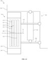
FIG. 1 is a block diagram of a vehicle that includes a tuned mass damper system. -
FIG. 2A is a block diagram that illustrates a portion of a vehicle, according to an implementation. -
FIG. 2B is a block diagram that illustrates a portion of a vehicle, according to an implementation. -
FIG. 3 is a schematic side view illustration of a wheel assembly for a vehicle, according to an implementation. -
FIG. 4 is a schematic side view illustration of a wheel assembly for a vehicle, according to another implementation. -
FIG. 5 is a schematic cross-sectional illustration of the wheel assembly ofFIG. 3 . -
FIG. 6 is a schematic cross-sectional illustration of the wheel assembly ofFIG. 3 in response to a force applied to the vehicle. - A tuned mass damper can be used to reduce unwanted vibration effects, such as wheel hop, which may be transmitted to a vehicle body. The tuned mass damper includes a damper mass coupled to a wheel assembly. The damper mass is smaller than the mass of a primary mass, such as the vehicle body, and oscillates to counter vibrations experienced by the wheel assembly. The oscillations of the damper mass result in a reduction of unwanted vibration effects.
- The tuned mass damper systems, included as part of a vehicle suspension system, include a damper mass that is coupled to an unsprung mass of the vehicle, such as a suspension knuckle (e.g., a hub retainer or wheel support) or vehicle wheel assembly. The damper mass of the tuned mass damper system is shaped such that a frontal force applied to the vehicle body, such as a side overlap impact, is transferred from the vehicle body to the damper mass by one or more engagement portions. The damper mass receives the transmitted force on one or more curved surfaces such that the damper mass and the attached wheel assembly rotate away from a longitudinal axis of the vehicle body. Throughout this disclosure, the same or similar reference numbers refer to the same or similar components.
-
FIG. 1 is a schematic block diagram of avehicle assembly 100 that includes asuspension system 106. A sprungmass 101 is coupled to anunsprung mass 103 with thesuspension system 106. The sprungmass 101 may include a vehicle body, unibody, frame, and/or related components. Theunsprung mass 103 may be a vehicle wheel assembly that includes, for example, a wheel, a tire, a wheel hub, a suspension knuckle, and friction braking components. Thesuspension system 106 includes asuspension component 116 that supports and/or regulates motion of the sprungmass 101 relative to theunsprung mass 103. Thesuspension component 116 may be a shock absorber, a spring, or a strut and may be one component of thesuspension system 106 of thevehicle assembly 100. - The
vehicle assembly 100 also includes a tuned mass damper system 108 (e.g., a vibration absorption system) coupled to theunsprung mass 103. The tunedmass damper system 108 includes adamper mass 110, aspring 112, and a fluid-operateddamper 114. The tunedmass damper system 108, or wheel hop damper, is a passive device that is configured to reduce vibration of an external portion to which it is mounted, such as theunsprung mass 103. In the illustrated implementation shown inFIG. 1 , the tunedmass damper system 108 is connected to theunsprung mass 103. Thedamper mass 110 moves with respect to and in response to movement of theunsprung mass 103. Selection of dynamic properties of thespring 112 and the fluid-operateddamper 114 can tune the movement of thedamper mass 110. The tuned movement of thedamper mass 110 is regulated by thespring 112 and the fluid-operateddamper 114 to counter vibration of theunsprung mass 103. Thespring 112 is connected to thedamper mass 110 and theunsprung mass 103 to resist motion of thedamper mass 110 away from a neutral position with respect to theunsprung mass 103. Thespring 112 also acts to bias thedamper mass 110 toward the neutral position with respect to theunsprung mass 103. The neutral position of thedamper mass 110 is a rest position with respect to theunsprung mass 103. Thedamper mass 110 will be located at the neutral position absent application of an external force to theunsprung mass 103. Thespring 112 supports thedamper mass 110 so that thedamper mass 110 can move in two directions with respect to the neutral position (e.g., positive and negative displacements with respect to an axis). The fluid-operateddamper 114 is connected to thedamper mass 110 and theunsprung mass 103 to resist movement of thedamper mass 110 with respect to the unsprung mass 103 (e.g., by resisting movements toward and away from the neutral position). - With reference to
FIGS. 2A and2B , a portion of thevehicle assembly 100 is schematically illustrated. Thevehicle assembly 100 may be a conventional road-traveling vehicle such as an automobile, SUV, truck, etc. that is supported by two or more wheel assemblies that each include a wheel and a tire. As an example, thevehicle assembly 100 may be a passenger vehicle. In another example, thevehicle assembly 100 may be a cargo vehicle. In yet another example, thevehicle assembly 100 may be any vehicle such as an airplane, etc. that includes a wheel assembly and for which reduced wheel hop is desired. - In the implementation shown in
FIGS. 2A and2B , thevehicle assembly 100 includes avehicle body 102, awheel assembly 104, abrake system 105 that includes arotor 130 and acaliper 132, thesuspension system 106, and the tunedmass damper system 108. Thevehicle body 102 includes components that are part of the sprungmass 101 of thevehicle assembly 100. In various implementations, thevehicle body 102 may be a multi-part structure or a unibody structure. Thevehicle body 102 includes, in some implementations, a frame, a subframe, a body, a monocoque, and/or other types of vehicle frame and body structures. Various support components such as frame rails, structural pillars, etc. that define internal structural aspects of thevehicle assembly 100 are also included as part of thevehicle body 102. Additionally, external body panels or other external portions of the vehicle are part of thevehicle body 102. - The
wheel assembly 104 includes awheel 118, atire 120, and awheel hub 122 and each of thewheel 118, thetire 120, and thewheel hub 122 are conventional components. Thewheel 118, in some implementations, is a steel or aluminum wheel that supports thetire 120, which may be a pneumatic tire. Thewheel hub 122 is an interface between non-rotating components of thesuspension system 106 of thevehicle assembly 100 and rotating components, such as thewheel 118 and thetire 120. - The
suspension system 106 includes, in some implementations, thesuspension component 116, a suspension knuckle 124 (e.g., a hub retainer or wheel support), anupper control arm 126, and alower control arm 128. Thesuspension knuckle 124 is located at least partially inside an internal space of thewheel 118 and serves as a support structure for components of thewheel assembly 104 and thebrake system 105. Thesuspension knuckle 124 is connected to thewheel hub 122 and supports thewheel 118 and thetire 120 to allow thewheel 118 and thetire 120 to rotate with respect to thesuspension knuckle 124. Thesuspension knuckle 124 is also connected to non-rotating components of thebrake system 105, such as thecaliper 132. Rotating components of thebrake system 105, such as therotor 130, are connected to thewheel hub 122 and/or thewheel 118. - The
upper control arm 126 and thelower control arm 128 connect thesuspension knuckle 124 to thevehicle body 102. Thesuspension knuckle 124 is movable relative to thevehicle body 102, primarily in a generally vertical direction (e.g., generally perpendicular to the direction of travel of the vehicle). In one example, theupper control arm 126 and thelower control arm 128 are each connected to thevehicle body 102 and to thesuspension knuckle 124 by pivot joints that allow rotation in one or more rotational degrees of freedom. Thesuspension component 116 is a suspension damper that is configured to regulate motion of thewheel assembly 104 with respect to thevehicle body 102. In various implementations, thesuspension component 116 is a shock, a strut, a spring, a linear actuator, or other active suspension component or passive suspension component. - The
brake system 105 provides deceleration torque for decelerating thevehicle assembly 100 using friction brake components, such as therotor 130 and thecaliper 132. Thecaliper 132 is configured to apply a braking force to therotor 130. In the implementation shown inFIG. 2A , thecaliper 132 is positioned at the top of therotor 130 and above an axis of rotation R of thewheel 118 and thetire 120. In the implementation shown inFIG. 2B , thecaliper 132 is positioned at the bottom of therotor 130 and below the axis of rotation R of thewheel 118 and thetire 120. The position of thecaliper 132 corresponds to the open end of thedamper mass 110 of the tunedmass damper system 108. For example, thedamper mass 110 may be positioned below thecaliper 132 in the implementation shown inFIG. 2A , and thedamper mass 110 may be positioned above thecaliper 132 in the implementation shown inFIG. 2B . The position of thedamper mass 110 is shown inFIGS. 3 and4 . - The tuned
mass damper system 108 is a passive suspension component that is part of thesuspension system 106 of thevehicle assembly 100. The tunedmass damper system 108 is configured to damp vibration of thewheel assembly 104, such as, for example, reducing the occurrence of wheel hop. The tunedmass damper system 108 damps vibration of thewheel assembly 104 by regulating movement of thedamper mass 110. By damping vibration of thewheel assembly 104, the tunedmass damper system 108 can reduce a transmission of vibration from theunsprung mass 103 to the sprungmass 101 of thevehicle assembly 100. -
FIG. 3 schematically illustrates a side view of thewheel assembly 104. Thesuspension knuckle 124 connects theupper control arm 126 and thelower control arm 128. Thesuspension knuckle 124 is also a support structure for the tunedmass damper system 108 and rotating and non-rotating components of thebrake system 105, including thecaliper 132 and therotor 130. - In the illustrated implementation, the tuned
mass damper system 108 includes thedamper mass 110,first spring 112a,second spring 112b,third spring 112c,fourth spring 112d, first fluid-operateddamper 114a, and second fluid-operateddamper 114b. Thedamper mass 110 has a firstmass portion 142, a secondmass portion 144, and a thirdmass portion 146 that connects the firstmass portion 142 and thesecond mass portion 144. The firstmass portion 142, thesecond mass portion 144, and the thirdmass portion 146 are geometric features of the tunedmass damper system 108 that promote rotation of thedamper mass 110 relative to a longitudinal axis of the vehicle when the vehicle is subjected to impact loads. - The first
mass portion 142 includes afirst bore 143 that extends generally vertically (e.g., perpendicular to the direction of travel of the vehicle ) through the firstmass portion 142. The first fluid-operateddamper 114a is located within thefirst bore 143. Thefirst spring 112a and thesecond spring 112b are mounted coaxially with the first fluid-operateddamper 114a. Thefirst spring 112a, thesecond spring 112b and the first fluid-operateddamper 114a extend through thefirst bore 143. Thefirst spring 112a extends from a firsttop mount 133 to an upper shoulder of thefirst bore 143. Thesecond spring 112b extends from a lower shoulder of thefirst bore 143 to afirst bottom mount 135. The upper shoulder of thefirst bore 143 and the lower shoulder of thefirst bore 143 act as bearing surfaces for thefirst spring 112a and thesecond spring 112b, respectively. Thefirst spring 112a and thesecond spring 112b surround the first fluid-operateddamper 114a and are configured to bias the damper mass 110 (i.e., a moving mass) toward a neutral or rest position of thedamper mass 110 with respect to the external portion (e.g., thesuspension knuckle 124 or other component of the unsprung mass 103) by acting against the bearing surfaces of the first shoulder and the second shoulder of thefirst bore 143, the firsttop mount 133, and the first bottom mount 135.The neutral position is a rest position for thedamper mass 110 with respect to thesuspension knuckle 124. Thedamper mass 110 will be located at the rest position absent application of an external force to the external portion (e.g., the suspension knuckle 124). The first fluid-operateddamper 114a is configured to regulate motion of thedamper mass 110 with respect to the external portion by movement of a fluid between first and second fluid chambers of the first fluid-operateddamper 114a. The first fluid-operateddamper 114a, thefirst spring 112a, and thesecond spring 112b define a first spring and fluid-operated damper assembly that extends at least partially through thefirst bore 143 in the firstmass portion 142 of thedamper mass 110 and is configured to regulate motion of thedamper mass 110 with respect to an external portion, such as thesuspension knuckle 124. - Similarly, the
second mass portion 144 includes asecond bore 145. Thesecond bore 145 extends generally vertically through thesecond mass portion 144. The second fluid-operateddamper 114b is located within thesecond bore 145. Thethird spring 112c and thefourth spring 112d are mounted coaxially with the second fluid-operateddamper 114b. Thethird spring 112c, thefourth spring 112d, and the second fluid-operateddamper 114b extend through thesecond bore 145. Thethird spring 112c extends from a secondtop mount 134 to an upper shoulder of thesecond bore 145. Thefourth spring 112d extends from a lower shoulder of thesecond bore 145 to asecond bottom mount 136. The upper shoulder of thesecond bore 145 and the lower shoulder of thesecond bore 145 act as bearing surfaces for thethird spring 112c and thefourth spring 112d, respectively. Thethird spring 112c and thefourth spring 112d surround the second fluid-operateddamper 114b are configured to bias thedamper mass 110 toward the neutral position of thedamper mass 110 relative to the externa structure by acting against the upper and lower bearing surfaces of thesecond bore 145, the secondtop mount 134 and thesecond bottom mount 136. The second fluid-operateddamper 114b is configured to regulate motion of thedamper mass 110 with respect to the external portion by movement of a fluid between first and second fluid chambers of the second fluid-operateddamper 114b. The second fluid-operateddamper 114b, thethird spring 112c, and thefourth spring 112d define a second spring and fluid-operated damper assembly that extends at least partially through thesecond bore 145 in thesecond mass portion 144 and is configured to regulate motion of thedamper mass 110 with respect to an external portion, such as thesuspension knuckle 124. - The third
mass portion 146 connects the firstmass portion 142 and thesecond mass portion 144 such that the firstmass portion 142, thesecond mass portion 144, and the thirdmass portion 146 form a compact, U-shaped configuration of thedamper mass 110 that minimizes the stack of hardware components in thewheel assembly 104. The thirdmass portion 146 forms a bottom of the U-shape with an open end opposite the thirdmass portion 146. In various implementations the firstmass portion 142 has a different shape and size than thesecond mass portion 144, that is, the firstmass portion 142 is larger and has a greater mass than thesecond mass portion 144. In the implementation illustrated inFIG. 3 , the firstmass portion 142 is disposed forward of thesecond mass portion 144 relative to a longitudinal axis A of thevehicle assembly 100. As shown inFIG. 3 , the firstmass portion 142 is positioned forward of the axis of rotation R of the rotating components of thewheel assembly 104 and thesecond mass portion 144 is positioned rearward of the axis of rotation R of the rotating components of thewheel assembly 104. The thirdmass portion 146 is positioned below the axis of rotation R inFIG. 3 . In various implementations, the firstmass portion 142, thesecond mass portion 144, and the thirdmass portion 146 are unitarily formed from a stiff and dense material, such as a metal, so that thedamper mass 110 has a mass that is sufficient to counteract vibrations experienced by thewheel assembly 104. While the implementation illustrated inFIG. 3 shows thedamper mass 110 as having a U-shaped configuration, it is understood that the damper mass may be formed in other configurations that preserve the position of the firstmass portion 142 and thesecond mass portion 144 on opposite sides of the axis of rotation R of the rotating components of the wheel assembly 104 (e.g., the firstmass portion 142 positioned forward of the axis of rotation R and thesecond mass portion 144 positioned rearward of the axis of rotation R) to facilitate the motion of the firstmass portion 142 relative to thesecond mass portion 144 in response to an applied force to thevehicle body 102. - With continued reference to
FIG. 3 , thewheel assembly 104 is disposed in a wheel opening defined in thevehicle body 102. Thevehicle body 102 includes a firstvehicle body portion 102a located forward of thewheel assembly 104 relative to the forward direction of travel of the vehicle and a secondvehicle body portion 102b located rearward of thewheel assembly 104 relative to the forward direction of travel of the vehicle. The firstvehicle body portion 102a is, in some implementations, a bumper or a forward portion of a wheel well. The firstvehicle body portion 102a includes afirst engagement portion 150. Thefirst engagement portion 150 is a geometric feature coupled to or extruded from thevehicle body 102 that extends from thevehicle body 102 such that a force applied to thevehicle body 102 causes thefirst engagement portion 150 to transfer the force applied to thevehicle body 102 to the firstmass portion 142 of thedamper mass 110. As a result of the force transferred to the firstmass portion 142 of thedamper mass 110, the tunedmass damper system 108 and thewheel assembly 104 rotate relative to the longitudinal axis of thevehicle body 102. Prior to an impact event, the tunedmass damper system 108 is a non-rotated and non-rotating component of the vehicle assembly 100 (e.g., the tunedmass damper system 108 does not rotate relative to a longitudinal axis of the vehicle). The force applied to thevehicle body 102 may be a side offset impact force such that the force transferred to the firstmass portion 142 of thedamper mass 110 causes thewheel assembly 104 and the tunedmass damper system 108 to rotate outward (i.e., the front of thewheel assembly 104 rotates away from the longitudinal axis of the vehicle body 102). Thefirst engagement portion 150 is configured to induce rotation of thewheel assembly 104 and the tunedmass damper system 108 during an impact event by interaction with thedamper mass 110. Interaction includes the transfer of the force applied to thevehicle body 102 through intervening structures between thefirst engagement portion 150 and thedamper mass 110 of the tuned mass damper system 108 (e.g., during deformation and/or breakage of the intervening structures). The intervening structures include components of thewheel assembly 104 such as thewheel 118 and thetire 120. - The second
vehicle body portion 102b is located rearward of thewheel assembly 104 relative to a forward direction of travel of the vehicle and is, in some implementations, a rear portion of a wheel well enclosure of thevehicle body 102. In some implementations, asecond engagement portion 152 is coupled to the secondvehicle body portion 102b. Thesecond engagement portion 152 is a geometric feature coupled to or extruded from thevehicle body 102 that extends from thevehicle body 102 such that the force applied to thevehicle body 102 causes thesecond engagement portion 152 to transfer the force applied to thevehicle body 102 to thesecond mass portion 144 of thedamper mass 110. Thesecond engagement portion 152 is configured to induce rotation of thewheel assembly 104 and the tunedmass damper system 108 during the impact event by interaction with thedamper mass 110. Interaction includes the transfer of the force applied to thevehicle body 102 through intervening structures between thesecond engagement portion 152 and thedamper mass 110 of the tuned mass damper system 108 (e.g., during deformation and/or breakage of the intervening structures). The intervening structures include components of thewheel assembly 104 such as thewheel 118 and thetire 120. In various implementations, thefirst engagement portion 150 and thesecond engagement portion 152 are portions of the tunedmass damper system 108 that cooperatively or together induce outward rotation of thewheel assembly 104 and the tunedmass damper system 108 and cooperatively rotate thewheel assembly 104 from a first position (shown inFIG. 5 ) to an outwardly rotated position (shown inFIG. 6 ) upon a frontal force applied to thevehicle body 102. The rotation of the tunedmass damper system 108 results in rotation of thedamper mass 110. - In the illustrated implementation, the
caliper 132 is positioned relative to thedamper mass 110 such that the thirdmass portion 146 of thedamper mass 110 is diametrically opposite thecaliper 132 relative to the axis of rotation R of thewheel assembly 104. In various implementations, thecaliper 132 is positioned relative to thedamper mass 110 such that the thirdmass portion 146 of thedamper mass 110 is generally opposite thecaliper 132 in a radial direction and is positioned on an opposite side of the axis of rotation R of thewheel assembly 104. As shown inFIG. 4 , thecaliper 132 is in a first position that is an upward position relative to thesuspension knuckle 124 and thecaliper 132 is above the axis of rotation R of thewheel assembly 104. Thedamper mass 110 is in a second position that is a downward position relative to thesuspension knuckle 124 such that the thirdmass portion 146 of thedamper mass 110 is opposite from thecaliper 132 and below the axis of rotation R of thewheel assembly 104, e.g., thedamper mass 110 does not move relative to an external portion, such as thesuspension knuckle 124. In various implementations, as shown inFIG. 4 , thecaliper 132 is positioned between the firsttop mount 133 and the secondtop mount 134. - In various implementations, as illustrated in
FIG. 5 , awheel assembly 204 includes thecaliper 132 and thedamper mass 110 in positions opposite the positions of these components shown inFIG. 4 . In this implementation, thecaliper 132 is positioned at a bottom position relative to thesuspension knuckle 124 and below the axis of rotation R of thewheel assembly 104. The thirdmass portion 146 of thedamper mass 110 is positioned at a top position relative to thesuspension knuckle 124 and above the axis of rotation R of thewheel assembly 104. In the illustrated implementation inFIG. 5 , thedamper mass 110 is positioned in an upside-down U-shape such that the thirdmass portion 146 is above thecaliper 132. - As shown in
FIG. 5 , thedamper mass 110 is oriented such that thesecond mass portion 144 is forward of the firstmass portion 142, that is, thesecond mass portion 144 is forward of the axis of rotation R of thewheel assembly 104 and the firstmass portion 142 is rearward of the axis of rotation R of thewheel assembly 104. In other configurations, thedamper mass 110 is oriented as shown inFIG. 4 with the firstmass portion 142 forward of thesecond mass portion 144 relative to the longitudinal axis A of the vehicle , that is, the firstmass portion 142 is forward of the axis of rotation R of thewheel assembly 104 and thesecond mass portion 144 is rearward of the axis of rotation R of the wheel assembly while the thirdmass portion 146 is below the axis of rotation R of the wheel assembly. In the illustrated configuration, thefirst engagement portion 150 transfers an impact force to thewheel assembly 204 and through deformation and/or breakage of components of thewheel assembly 204 to thesecond mass portion 144 of thedamper mass 110. Thesecond engagement portion 152 transfers the impact force to thewheel assembly 204 and the firstmass portion 142 of thedamper mass 110. Thefirst engagement portion 150 and thesecond engagement portion 152 cooperatively act to rotate thewheel assembly 204 away from the longitudinal axis of thevehicle assembly 100, that is to rotate thewheel assembly 204 outward and away from the longitudinal axis of thevehicle assembly 100. - With reference now to
FIG. 5 , thewheel assembly 104 is shown in cross-section. Thewheel assembly 104 includes thewheel 118 and thetire 120, as well as a wheel hub (not shown) that acts as the interface between non-rotating components of thesuspension system 106 of thevehicle assembly 100 and rotating components, such as thewheel 118 and thetire 120. Arotor 130 is connected to thewheel 118 for rotation with the wheel 118 (e.g., the rotor rotates in unison with the wheel 118). - The
damper mass 110 includes the firstmass portion 142, thesecond mass portion 144, and the thirdmass portion 146. The thirdmass portion 146 extends between the firstmass portion 142 and thesecond mass portion 144 and connects the firstmass portion 142 and thesecond mass portion 144. - The first
mass portion 142 has a firstcurved surface 162 defined at afirst end 148 of thedamper mass 110. The firstcurved surface 162 faces a first direction, which is a forward direction as illustrated inFIG. 5 , and the first direction is away from thesecond mass portion 144. The firstcurved surface 162 also faces laterally inward relative to a lateral axis B of thevehicle body 102. The firstcurved surface 162 extends vertically, that is, in a plane perpendicular to a lateral direction of thevehicle body 102, from the open end of thedamper mass 110 to the thirdmass portion 146 that forms the closed end, or bottom of the U-shaped configuration, of thedamper mass 110. This orientation of the firstcurved surface 162 of the firstmass portion 142 induces rotation of thedamper mass 110 and thewheel assembly 104 when the firstcurved surface 162 receives the force applied to thevehicle body 102 that is transferred through thefirst engagement portion 150 and the deformation and/or breakage of intervening components of thewheel assembly 104. Thefirst engagement portion 150 has a geometric configuration that is designed to interact, through the intervening components of thewheel assembly 104, with the firstcurved surface 162 and rotate the firstmass portion 142 laterally outward. The geometric configuration of thefirst engagement portion 150 is a configuration that directs the force applied to thevehicle body 102 to the area on the firstcurved surface 162 that induces lateral outward rotation of the firstmass portion 142 of thedamper mass 110. The firstcurved surface 162 is configured to receive a force applied to thevehicle body 102, such as during a small overlap impact where impact forces are concentrated on a front corner of thevehicle body 102 and rotate theconnected wheel assembly 104 outward relative to the longitudinal axis A of thevehicle body 102. The force from the impact event is transferred through thefirst engagement portion 150 and through the crushable components of thewheel assembly 104 to thedamper mass 110 such that the transferred force is applied at an area on the firstcurved surface 162 to rotate thewheel assembly 104 and tunedmass damper system 108 in a first or outward direction away from a center of thevehicle body 102. The force transferred to thedamper mass 110 is applied at the firstcurved surface 162 of the firstmass portion 142 and causes rotation between the firstmass portion 142 and thesecond mass portion 144, that is, the firstmass portion 142 rotates relative to thesecond mass portion 144. - The first
mass portion 142 includes a firstflat surface 164 that faces therotor 130. The firstflat surface 164 is part of a side surface of thedamper mass 110 and is generally planar with the thirdmass portion 146. The outward facing side surface partially defined by the firstflat surface 164 is generally planar and is adjacent to therotor 130. - The
second mass portion 144 includes a secondcurved surface 166 defined at asecond end 149 of thedamper mass 110. The secondcurved surface 166 faces a second direction and opposite direction from the first direction, which is a rearward direction as illustrated inFIG. 5 , and the second direction is generally away or an opposite direction from the firstmass portion 142. The secondcurved surface 166 also faces laterally outward relative to the lateral axis B of thevehicle body 102. The secondcurved surface 166 extends vertically, that is, in a plane perpendicular to a lateral direction of thevehicle body 102, from the open end of thedamper mass 110 toward the thirdmass portion 146 that forms the closed end, or bottom of the U-shaped configuration, of thedamper mass 110. This orientation of the secondcurved surface 166 of thesecond mass portion 144 induces inward rotation of thedamper mass 110 when thesecond mass portion 144 receives the force applied to thevehicle body 102 that is transferred through thesecond engagement portion 152 and the deformation and/or breakage of intervening components of thewheel assembly 104. The secondcurved surface 166 is configured to receive the force applied to thevehicle body 102, such as a force from a small overlap impact, and rotate theconnected wheel assembly 104 laterally inward relative to the longitudinal axis A of thevehicle body 102. The force from the impact event is transferred through thesecond engagement portion 152 and through the crushable components of thewheel assembly 104 to thedamper mass 110 such that the transferred force is applied at an area on the secondcurved surface 166 to rotate thewheel assembly 104 and the tunedmass damper system 108 in a second or laterally inward direction toward a center of thevehicle body 102. In various implementations, the force applied to thevehicle body 102 is transferred by thefirst engagement portion 150 through the deformable components of thewheel assembly 104 to the firstcurved surface 162 of the firstmass portion 142. The resultant translation and/or rotation of thewheel assembly 104 and thedamper mass 110 results in interaction between thesecond engagement portion 152 and the secondcurved surface 166 of thesecond mass portion 144 through the deformable components of thewheel assembly 104. Thesecond mass portion 144 includes a secondflat surface 168 positioned on an opposite side of thedamper mass 110 away from therotor 130. In various implementations, the curved and flat surfaces of the firstmass portion 142 and thesecond mass portion 144 are designed for packaging and force transfer considerations. - The third
mass portion 146 has a width D in a lateral direction, that is, parallel to the lateral axis B of thevehicle body 102, that is smaller than a width of the firstmass portion 142 and a width of thesecond mass portion 144 such that the thirdmass portion 146 is thinner in the lateral direction than the firstmass portion 142 and thesecond mass portion 144. In various implementations, the width D of the thirdmass portion 146 is thinner than a minimum lateral dimension of the firstmass portion 142 and a minimum lateral dimension of thesecond mass portion 144. In some implementations, the width D of the thirdmass portion 146 is thinner than an adjacent portion of the firstmass portion 142 where the firstmass portion 142 meets the thirdmass portion 146. In some implementations, the width D of the thirdmass portion 146 is thinner than an adjacent portion of thesecond mass portion 144 where thesecond mass portion 144 meets the thirdmass portion 146. The width D is, in some embodiments, a minimum lateral dimension of the thirdmass portion 146 at a position that is equidistant between the firstmass portion 142 and thesecond mass portion 144. In various implementations, the thirdmass portion 146 has a cross-sectional area at a position between the firstmass portion 142 and thesecond mass portion 144 that is smaller than other positions within the thirdmass portion 146 in a plane that extends perpendicular to the longitudinal axis of thevehicle body 102. - The third
mass portion 146 is designed to be a deformable and frangible component of thedamper mass 110 such that, in the event of an impact, thedamper mass 110 separates within the thirdmass portion 146. In one example, thedamper mass 110 is configured to separate by fracturing within the thirdmass portion 146. The width D of the thirdmass portion 146 is designed to be at an area where a maximum concentration of stress resultant from the applied force results in separation of the firstmass portion 142 from thesecond mass portion 144 such that there is relative motion between the firstmass portion 142 and thesecond mass portion 144. Stress on thedamper mass 110 from the force applied to thevehicle body 102 may be present at different points on thedamper mass 110, such as, for example, the area of impact on the firstcurved surface 162 of the firstmass portion 142 by thefirst engagement portion 150. However, the position within the thirdmass portion 146 that has a minimum cross-sectional area as compared to other the cross-sectional area of adjacent areas of the thirdmass portion 146 is one area of high stress concentration that can result in separation of the firstmass portion 142 from thesecond mass portion 144 by fracture at the minimum cross-sectional area of the thirdmass portion 146 such that the firstmass portion 142 moves relative to thesecond mass portion 144. The area of high stress concentration within the thirdmass portion 146 depends on the material selection and manufacturing process of thedamper mass 110. The selection of the material and manufacturing process of thedamper mass 110 is controlled such that the motion of the firstmass portion 142 relative to thesecond mass portion 144 is achieved via separation or fracture at the minimum cross-sectional area of the thirdmass portion 146. - In various implementations, the
first engagement portion 150 is a geometric change to the underlying structure of thevehicle body 102. Thefirst engagement portion 150 is coupled to or formed integrally with thevehicle body 102. Thefirst engagement portion 150 can have any shape, such as a hammer, wedge, or other protrusion configured to transfer an impact force applied to thevehicle body 102 to thewheel assembly 104 and thedamper mass 110 of the tunedmass damper system 108. Thefirst engagement portion 150 is positioned forward of thewheel assembly 104. Thefirst engagement portion 150 may be positioned inward of a vehicle bumper or inside a wheel well enclosure such that thefirst engagement portion 150 is not visible from a position exterior of thevehicle body 102. Thefirst engagement portion 150 is positioned such that the force applied to thevehicle body 102 is transferred to the area on the firstcurved surface 162 of the firstmass portion 142 to induce outward rotation of thedamper mass 110 and the attachedwheel assembly 104. - Similarly, the
second engagement portion 152 is a geometric change to the underlying structure of thevehicle body 102. Thesecond engagement portion 152 is coupled to or integrally formed with thevehicle body 102. Thesecond engagement portion 152 protrudes from the underlying structure of thevehicle body 102 toward thesecond mass portion 144 of thedamper mass 110 and is positioned such that the force applied to thevehicle body 102 is transferred to the area on the secondcurved surface 166 to induce inward rotation of thedamper mass 110 and the attachedwheel assembly 104. Thesecond engagement portion 152 is positioned rearward of thewheel assembly 104 and tunedmass damper system 108 and may be inside the wheel well enclosure such that thesecond engagement portion 152 is not visible from a position exterior of thevehicle body 102. - The
damper mass 110 is a generally rigid, noncrushable component, in contrast to the other components of the wheel assembly 104 (e.g., thewheel 118, tire 120) that crush or deform in response to the force applied to thevehicle body 102.FIG. 6 illustrates the reaction of thewheel assembly 104 and the tunedmass damper system 108 in response to an impact force F, such as a small overlap impact, applied to a front corner of thevehicle body 102. The force F is transferred from thefirst engagement portion 150 to the crushable components of the wheel assembly 104 (e.g., thewheel 118 and the tire 120). The force is applied at the area on the firstcurved surface 162 of the firstmass portion 142 to rotate thewheel assembly 104 and tunedmass damper system 108 in a generally outward direction relative to the longitudinal axis A of thevehicle body 102. The impact force F also translates thewheel assembly 104 rearward such that thesecond engagement portion 152 contacts the crushable components of thewheel assembly 104. The force from thesecond engagement portion 152 is transferred through the crushable components and is applied at the area on the secondcurved surface 166 to further induce rotation of thewheel assembly 104 and tunedmass damper system 108 such that thesecond end 149 of thedamper mass 110 rotates inward and toward the longitudinal axis A of thevehicle body 102. Thesecond engagement portion 152 may function as a reaction surface for the impact force F applied to thevehicle body 102 such that the interaction between thesecond engagement portion 152 and thesecond mass portion 144 of thedamper mass 110 rotates thewheel assembly 104 away from the longitudinal axis A of thevehicle body 102. - The third
mass portion 146 includes a portion of stress concentration C that is positioned anywhere within the thirdmass portion 146. The portion of stress concentration C is generally where the lateral width D of the third mass portion 146 (shown inFIG. 5 ) is a minimum width such that a fracture of thedamper mass 110 due to the impact force F is likely to occur within the portion of stress concentration C of the thirdmass portion 146. The portion of stress concentration C is the highest area of stress concentration between part of the firstmass portion 142 and thesecond mass portion 144. Thedamper mass 110 may include multiple areas of stress concentration, but separation of the firstmass portion 142 from thesecond mass portion 144 due to fracture of the thirdmass portion 146 is most likely to occur at the portion of stress concentration C. - As described above, one aspect of the present technology is suspension control, which may, in some implementations, include the gathering and use of data available from various sources to customize operation based on user preferences. As an example, such data may identify the user and include user-specific settings or preferences. The present disclosure contemplates that in some instances, this gathered data may include personal information data that uniquely identifies or can be used to contact or locate a specific person. Such personal information data can include demographic data, location-based data, telephone numbers, email addresses, twitter ID's, home addresses, data or records relating to a user's health or level of fitness (e.g., vital signs measurements, medication information, exercise information), date of birth, or any other identifying or personal information.
- The present disclosure recognizes that the use of such personal information data, in the present technology, can be used to the benefit of users. For example, a user profile may be established that stores user preferences for user comfort levels with regard to, for example suspension system stiffness. Accordingly, use of such personal information data enhances the user's experience.
- The present disclosure contemplates that the entities responsible for the collection, analysis, disclosure, transfer, storage, or other use of such personal information data will comply with well-established privacy policies and/or privacy practices. In particular, such entities should implement and consistently use privacy policies and practices that are generally recognized as meeting or exceeding industry or governmental requirements for maintaining personal information data private and secure. Such policies should be easily accessible by users, and should be updated as the collection and/or use of data changes. Personal information from users should be collected for legitimate and reasonable uses of the entity and not shared or sold outside of those legitimate uses. Further, such collection/sharing should occur after receiving the informed consent of the users. Additionally, such entities should consider taking any needed steps for safeguarding and securing access to such personal information data and ensuring that others with access to the personal information data adhere to their privacy policies and procedures. Further, such entities can subject themselves to evaluation by third parties to certify their adherence to widely accepted privacy policies and practices. In addition, policies and practices should be adapted for the particular types of personal information data being collected and/or accessed and adapted to applicable laws and standards, including jurisdiction-specific considerations. For instance, in the US, collection of or access to certain health data may be governed by federal and/or state laws, such as the Health Insurance Portability and Accountability Act (HIPAA); whereas health data in other countries may be subject to other regulations and policies and should be handled accordingly. Hence different privacy practices should be maintained for different personal data types in each country.
- Despite the foregoing, the present disclosure also contemplates embodiments in which users selectively block the use of, or access to, personal information data. That is, the present disclosure contemplates that hardware and/or software elements can be provided to prevent or block access to such personal information data. For example, in the case of storing a user profile for identifying user comfort levels and preferences, the present technology can be configured to allow users to select to "opt in" or "opt out" of participation in the collection of personal information data during registration for services or anytime thereafter. In another example, users can select not to provide data regarding usage of specific applications. In yet another example, users can select to limit the length of time that application usage data is maintained or entirely prohibit the development of an application usage profile. In addition to providing "opt in" and "opt out" options, the present disclosure contemplates providing notifications relating to the access or use of personal information. For instance, a user may be notified upon downloading an app that their personal information data will be accessed and then reminded again just before personal information data is accessed by the app.
- Moreover, it is the intent of the present disclosure that personal information data should be managed and handled in a way to minimize risks of unintentional or unauthorized access or use. Risk can be minimized by limiting the collection of data and deleting data once it is no longer needed. In addition, and when applicable, including in certain health related applications, data de-identification can be used to protect a user's privacy. De-identification may be facilitated, when appropriate, by removing specific identifiers (e.g., date of birth, etc.), controlling the amount or specificity of data stored (e.g., collecting location data a city level rather than at an address level), controlling how data is stored (e.g., aggregating data across users), and/or other methods.
- Therefore, although the present disclosure broadly covers use of personal information data to implement one or more various disclosed embodiments, the present disclosure also contemplates that the various embodiments can also be implemented without the need for accessing such personal information data. That is, the various embodiments of the present technology are not rendered inoperable due to the lack of all or a portion of such personal information data. For example, suspension control can be performed using non-personal information data or a bare minimum amount of personal information, other non-personal information available to the devices, or publicly available information.
Claims (15)
- A vibration absorption system, comprising:a damper mass including a first mass portion and a second mass portion connected by a third mass portion such that the first mass portion, the second mass portion, and the third mass portion form a U-shaped configuration of the damper mass,wherein the damper mass is configured to separate within the third mass portion in response to a force transferred to the damper mass of the vibration absorption system to allow relative motion between the first mass portion and the second mass portion.
- The vibration absorption system according to claim 1, wherein the third mass portion is thinner in a lateral direction than the first mass portion and the second mass portion.
- The vibration absorption system according to any of claims 1 and 2, wherein the damper mass includes a portion of stress concentration within the third mass portion such that the third mass portion is configured to separate within the portion of stress concentration in response to the force transferred to the damper mass of the vibration absorption system to allow relative motion between the first mass portion and the second mass portion.
- The vibration absorption system according to any of claims 1-3, wherein the first mass portion is larger and has a greater mass than the second mass portion.
- The vibration absorption system according to any of claims 1-4, wherein the first mass portion has a first curved surface defined at a first end of the damper mass facing a first direction away from the second mass portion and the second mass portion has a second curved surface defined at a second end of the damper mass facing in a second and opposite direction away from the first mass portion, the force transferred to the damper mass is applied at the first curved surface of the first mass portion, and the damper mass is configured to rotate in response to the force applied at the first curved surface.
- The vibration absorption system according to claim 5, wherein the force transferred to the damper mass includes a first force applied at the first curved surface of the damper mass and a second force applied at the second curved surface of the damper mass, and the vibration absorption system is configured to rotate in response to the first force applied at the first curved surface and the second force applied at the second curved surface.
- The vibration absorption system according to any of claims 1-5, further comprising:a first spring and fluid-operated damper assembly that is configured to regulate motion of the damper mass with respect to an external portion; anda second spring and fluid-operated damper assembly that is configured to regulate motion of the damper mass with respect to the external portion,wherein the first mass portion includes a first bore and the second mass portion includes a second bore, the first spring and fluid-operated damper assembly extends at least partially through the first bore in the first mass portion, and the second spring and fluid-operated damper assembly extends at least partially through the second bore in the second mass portion.
- The vibration absorption system according to any of claims 1-5, wherein the damper mass is positioned relative to a caliper of a brake system coupled to a wheel assembly such that the third mass portion of the damper mass is diametrically opposite the caliper.
- The vibration absorption system according to claim 8, wherein a first position of the caliper is an upward position relative to a wheel support such that the caliper is above an axis of rotation of the wheel assembly and a second position of the damper mass is a downward position relative to the wheel support such that the third mass portion is opposite from the caliper relative to the axis of rotation of the wheel assembly.
- The vibration absorption system according to claim 8, wherein a first position of the caliper is a bottom position relative to a wheel support and a second position of the damper mass is a top position relative to the wheel support.
- The vibration absorption system according to claim 8, further comprising an engagement portion coupled to a vehicle body and extending toward the wheel assembly, the engagement portion having a geometric configuration that is configured to induce rotation of the wheel assembly away from a longitudinal axis of a vehicle during an impact to the vehicle body by interaction of the engagement portion with the damper mass.
- The vibration absorption system according to claim 8, further comprising an engagement portion coupled to a vehicle body, wherein the engagement portion is a geometric feature of the vehicle body that extends toward the damper mass and the engagement portion is configured to transfer a force to the damper mass.
- The vibration absorption system according to claim 12, wherein the engagement portion is a first engagement portion and the vibration absorption system and the wheel assembly are configured to rotate relative to a longitudinal axis of the vehicle body in response to a force transferred from the first engagement portion to the first mass portion of the damper mass.
- The vibration absorption system according to claim 13, further comprising a second engagement portion extending from the vehicle body, wherein the second engagement portion functions as a reaction surface for the impact to the vehicle body and the wheel assembly is configured to rotate away from the longitudinal axis of the vehicle in response to an interaction between the second engagement portion and the second mass portion of the damper mass.
- The vibration absorption system according to claim 14, wherein the first engagement portion is positioned forward of the wheel assembly and the second engagement portion is positioned rearward of the wheel assembly, and the first engagement portion and the second engagement portion are configured to cooperatively induce outward rotation of the wheel assembly upon a frontal force applied to the vehicle body.
Applications Claiming Priority (1)
| Application Number | Priority Date | Filing Date | Title |
|---|---|---|---|
| US202263351070P | 2022-06-10 | 2022-06-10 |
Publications (1)
| Publication Number | Publication Date |
|---|---|
| EP4289641A1 true EP4289641A1 (en) | 2023-12-13 |
Family
ID=86731928
Family Applications (1)
| Application Number | Title | Priority Date | Filing Date |
|---|---|---|---|
| EP23177907.5A Withdrawn EP4289641A1 (en) | 2022-06-10 | 2023-06-07 | Vibration absorber |
Country Status (4)
| Country | Link |
|---|---|
| US (1) | US12251973B2 (en) |
| EP (1) | EP4289641A1 (en) |
| JP (1) | JP2023181106A (en) |
| CN (1) | CN117212377A (en) |
Citations (1)
| Publication number | Priority date | Publication date | Assignee | Title |
|---|---|---|---|---|
| US20130341143A1 (en) * | 2012-06-26 | 2013-12-26 | Bose Corporation | Tuned vibration absorber for active vehicle suspension |
Family Cites Families (365)
| Publication number | Priority date | Publication date | Assignee | Title |
|---|---|---|---|---|
| US2537479A (en) | 1946-02-12 | 1951-01-09 | Motte Charles Marius | Combined suspension hub and shock absorber for vehicle wheels |
| US2757938A (en) | 1954-04-09 | 1956-08-07 | Charles W Crowder | Hydraulic motor vehicle stabilizer |
| US2955841A (en) | 1956-05-31 | 1960-10-11 | Gen Motors Corp | Wheel hop damper |
| US2901239A (en) | 1956-09-10 | 1959-08-25 | Bendix Aviat Corp | Suspension system |
| US2913252A (en) | 1957-08-02 | 1959-11-17 | Pacific Car & Foundry Co | Vehicle suspension using air spring |
| DE1183805B (en) | 1958-02-21 | 1964-12-17 | Daimler Benz Ag | Device for influencing the curve inclination of vehicles, in particular motor vehicles |
| US3231058A (en) | 1962-02-19 | 1966-01-25 | Raybestos Manhattan Inc | Friction device |
| US3236334A (en) | 1964-01-06 | 1966-02-22 | Lord Mfg Co | Vibration suppressor |
| US3322379A (en) | 1964-11-03 | 1967-05-30 | Kaman Aircraft Corp | Dynamic antiresonant vibration isolator |
| FR1439054A (en) | 1965-02-02 | 1966-05-20 | Commerciale Paulstra Soc | Improvements to vehicle suspension systems |
| US3441238A (en) | 1967-05-26 | 1969-04-29 | Kaman Corp | Dynamic antiresonant vibration isolator |
| US3781032A (en) | 1972-04-24 | 1973-12-25 | V Jones | Trailing arm suspension system |
| FR2265565B1 (en) | 1974-03-28 | 1977-06-17 | Peugeot & Renault | |
| GB2006131A (en) | 1977-10-21 | 1979-05-02 | Vauxhall Motors Ltd | Motor vehicle roll control system |
| US4379572A (en) | 1980-05-12 | 1983-04-12 | Hedenberg William E | Universal air suspension system |
| US4537420A (en) | 1981-07-28 | 1985-08-27 | Nissan Motor Company, Limited | Swing-arm-type suspension with a lateral rod for an automotive vehicle |
| JPS58185306A (en) | 1982-04-26 | 1983-10-29 | Nissan Motor Co Ltd | Trailing arm type suspension with lateral link |
| US4634142A (en) | 1983-08-15 | 1987-01-06 | C & K Venture Income I-Coast | Computer optimized adaptive suspension system |
| US4893832A (en) | 1983-08-22 | 1990-01-16 | Suspension Group, Ltd. | Dihedral composite vehicle suspension |
| JPS60179317A (en) | 1984-02-25 | 1985-09-13 | Honda Motor Co Ltd | vehicle suspension device |
| US4656409A (en) | 1984-06-22 | 1987-04-07 | Honda Giken Kogyo Kabushiki Kaisha | Electromagnetic servo unit |
| US4589678A (en) | 1985-03-19 | 1986-05-20 | Allan J. Kuebler | Anti-roll system for a vehicle |
| JPH0530483Y2 (en) | 1985-03-20 | 1993-08-04 | ||
| US4614359A (en) | 1985-03-21 | 1986-09-30 | General Motors Corporation | Vehicle wheel with height adjustment |
| DE3510335A1 (en) | 1985-03-22 | 1986-10-16 | Adam Opel AG, 6090 Rüsselsheim | MOTOR VEHICLE |
| US4613152A (en) | 1985-05-01 | 1986-09-23 | Booher Benjamin V | Composite transverse beam and spring system for an automobile |
| US4784378A (en) | 1985-11-14 | 1988-11-15 | Ford Motor Company | Vibrating body mounting assembly |
| US4637628A (en) | 1985-12-02 | 1987-01-20 | Chrysler Motors Corporation | Anti-roll torsion bar arrangement for vehicle rear suspension |
| DE3707162A1 (en) | 1986-03-11 | 1987-10-01 | Mazda Motor | REAR SUSPENSION FOR VEHICLES |
| JPS63284067A (en) | 1987-05-13 | 1988-11-21 | Honda Motor Co Ltd | Wheel steering device |
| DE3738949A1 (en) | 1987-11-17 | 1989-05-24 | Textar Gmbh | BRAKE FOR ROAD, RAIL AND AIRCRAFT |
| US4922159A (en) | 1988-05-09 | 1990-05-01 | Harris Corporation | Linear precision actuator with accelerometer feedback |
| US4991698A (en) | 1988-05-16 | 1991-02-12 | Bose Corporation | Damping with damping mass inside wheel |
| DE68903245T2 (en) | 1988-05-16 | 1993-09-16 | Bose Corp | VEHICLE SUSPENSION SYSTEM. |
| GB8815694D0 (en) | 1988-07-01 | 1988-08-10 | Lotus Group Plc | Vehicle suspension system |
| US5027048A (en) | 1988-10-05 | 1991-06-25 | Ford Motor Company | Field oriented motor controller for electrically powered active suspension for a vehicle |
| US5060959A (en) | 1988-10-05 | 1991-10-29 | Ford Motor Company | Electrically powered active suspension for a vehicle |
| US6470248B2 (en) | 1989-01-11 | 2002-10-22 | Narton Corporation | Vehicle suspension control system |
| US4960290A (en) | 1989-05-10 | 1990-10-02 | Bose Corporation | Wheel assembly suspending |
| US4926978A (en) | 1989-05-25 | 1990-05-22 | Honda Giken Kogyo Kabushiki Kaisha | Friction pad for use with disc brake |
| US4981309A (en) | 1989-08-31 | 1991-01-01 | Bose Corporation | Electromechanical transducing along a path |
| US5033028A (en) | 1989-12-27 | 1991-07-16 | At&T Bell Laboratories | Reaction mass actuator |
| DE4037223A1 (en) | 1990-04-24 | 1991-10-31 | Bosch Gmbh Robert | VEHICLE SUPPORT SYSTEM |
| JP3132511B2 (en) | 1991-01-10 | 2001-02-05 | マツダ株式会社 | Car suspension support structure |
| DE4102787C2 (en) | 1991-01-31 | 1998-07-30 | Daimler Benz Ag | Suspension system, in particular for motor vehicles |
| US5172930A (en) | 1991-03-06 | 1992-12-22 | Boye Brian A | Load leveling attachment for leaf spring suspension and method therefor |
| GB9119103D0 (en) | 1991-09-07 | 1991-10-23 | Motor Ind Res Ass | Suspension system |
| US5409254A (en) | 1992-05-11 | 1995-04-25 | A. O. Smith Corporation | Rear suspension with aligned coil springs and twist beam axle |
| US5251926A (en) | 1992-07-06 | 1993-10-12 | General Motors Corporation | Ratchet assembly for an adjustable stabilizer bar |
| DE4231641C2 (en) | 1992-09-22 | 1996-12-12 | Daimler Benz Ag | Suspension strut for automotive suspension systems |
| JPH06183365A (en) | 1992-12-17 | 1994-07-05 | Kenji Mimura | Suspension device for vehicle |
| US5392882A (en) | 1993-02-03 | 1995-02-28 | General Motors Corporation | Dynamic absorber suspension strut |
| US6032770A (en) | 1993-04-12 | 2000-03-07 | Raytheon Company | Low force actuator for suspension control |
| FR2705418B1 (en) | 1993-05-14 | 1995-08-04 | Hutchinson | Vehicle noise attenuation device. |
| US5645250A (en) | 1993-08-26 | 1997-07-08 | Gevers; David E. | Multi-purpose aircraft |
| US5507518A (en) | 1993-12-24 | 1996-04-16 | Yorozu Corporation | Torsion beam type suspension and method for production thereof |
| FR2717874B1 (en) | 1994-03-25 | 1996-04-26 | Gec Alsthom Transport Sa | Multimaterial disc for high energy braking. |
| US5517414A (en) | 1994-10-03 | 1996-05-14 | Ford Motor Company | Traction control system with active suspension |
| JPH08197931A (en) | 1995-01-23 | 1996-08-06 | Honda Motor Co Ltd | Active suspension |
| GB9514974D0 (en) | 1995-07-21 | 1995-09-20 | Rover Group | A semi-trailing arm suspension for a vehicle |
| US5785345A (en) | 1995-10-16 | 1998-07-28 | The Boler Company | Means for and method of controlling frame rise in vehicle suspensions |
| DE19606991C2 (en) | 1996-02-24 | 1998-11-12 | Daimler Benz Ag | Spring vibration damper device of a motor vehicle |
| US6940248B2 (en) | 1996-07-05 | 2005-09-06 | Bose Corporation | Motion controlling |
| US6398251B1 (en) | 1997-01-31 | 2002-06-04 | Dallas Smith Corporation | Axleless vehicle suspension system |
| FR2763300A1 (en) | 1997-05-16 | 1998-11-20 | Conception & Dev Michelin Sa | VEHICLE HAVING A SUSPENSION HAVING AN ACTIVE BODY VARIATION |
| FR2763284A1 (en) | 1997-05-16 | 1998-11-20 | Conception & Dev Michelin Sa | PACKAGE INCLUDING A WHEEL AND INTEGRATED WHEEL SUSPENSION |
| US5880542A (en) | 1997-05-30 | 1999-03-09 | Satcon Technology Corporation | Light reaction mass actuator |
| US6260869B1 (en) | 1997-07-31 | 2001-07-17 | Excelsior-Henderson Motorcyle Co. | Motorcycle front suspension system |
| JP3425745B2 (en) | 1997-08-04 | 2003-07-14 | トヨタ自動車株式会社 | Vehicle suspension |
| US6152267A (en) | 1997-09-23 | 2000-11-28 | Honda Giken Kogyo Kabushiki Kaisha | Caliper structure for link-type front suspension |
| US6364078B1 (en) | 1998-08-27 | 2002-04-02 | Bose Corporation | Wheel damping |
| JP3787038B2 (en) | 1998-09-10 | 2006-06-21 | トヨタ自動車株式会社 | Elastic support device, vehicle elastic support device, and control device for vehicle suspension device |
| DE19850169C1 (en) | 1998-10-30 | 2000-07-27 | Heynau Antriebstechnik Gmbh | Drive unit has electric motor with external teeth with which it is supported on inner teeth of common housing forming ring gear teeth of planetary gear |
| WO2000027659A1 (en) | 1998-11-11 | 2000-05-18 | Kenmar Company Trust | Enhanced computer optimized adaptive air spring suspension |
| DE19853876A1 (en) | 1998-11-23 | 2000-05-25 | Zahnradfabrik Friedrichshafen | Suspension and rolling motion stabilizer for motor vehicles with pressure medium-charged conduit containing transfer medium to connect suspension systems of both vehicle sides |
| DE19855310C2 (en) | 1998-12-01 | 2000-10-05 | Daimler Chrysler Ag | Active suspension system for vehicles |
| US6357770B1 (en) | 1999-10-07 | 2002-03-19 | CARPIAUX ANDRé | In-wheel suspension |
| US6233510B1 (en) | 1999-10-15 | 2001-05-15 | Meritor Heavy Vehicle Technology, Llc | Method and system for predicting road profile |
| US6637561B1 (en) | 1999-11-11 | 2003-10-28 | Raytheon Company | Vehicle suspension system |
| US7195250B2 (en) | 2000-03-27 | 2007-03-27 | Bose Corporation | Surface vehicle vertical trajectory planning |
| US6276710B1 (en) | 2000-04-19 | 2001-08-21 | Inernational Truck And Engine Corporation | Articulating air spring suspension for tandem axle |
| US6865466B2 (en) | 2000-04-27 | 2005-03-08 | American Axle & Manufacturing, Inc. | Active vibration cancellation of gear mesh vibration |
| DE10025493B4 (en) | 2000-05-23 | 2008-05-29 | Daimler Ag | Method and device for coordinating a plurality of driving system devices of a vehicle |
| US7017690B2 (en) | 2000-09-25 | 2006-03-28 | Its Bus, Inc. | Platforms for sustainable transportation |
| US6513819B1 (en) | 2000-11-28 | 2003-02-04 | Delphi Technologies, Inc. | Hydraulically actuated sway bar latch |
| US6443436B1 (en) | 2001-05-29 | 2002-09-03 | Tenneco Automotive Inc. | Air spring assembly on shock absorber with combined seal |
| US6517089B2 (en) | 2001-06-14 | 2003-02-11 | Delphi Technologies, Inc. | Torsion bar actuator for suspension trim height and roll control |
| US20030030241A1 (en) | 2001-08-13 | 2003-02-13 | Lawson Robert Christian | Intergrated cross-car suspension system with damper strut |
| US6752250B2 (en) | 2001-09-27 | 2004-06-22 | Northrop Grumman Corporation | Shock, vibration and acoustic isolation system |
| AUPR801301A0 (en) | 2001-09-28 | 2001-10-25 | Kinetic Pty Limited | Vehicle suspension system |
| US6832772B2 (en) | 2001-10-26 | 2004-12-21 | Peterson & Erb | Vehicle center section adjustable anti-roll bar |
| US7597169B2 (en) | 2001-12-07 | 2009-10-06 | Gm Global Technology Operations, Inc. | Wheel module |
| US6634445B2 (en) | 2001-12-27 | 2003-10-21 | Case Corporation | Skid steer vehicle having suspensions that are locked based on vehicle speed |
| MXPA04007361A (en) | 2002-02-01 | 2005-03-31 | Holland Group Inc | Trailing arm suspension with optimized i-beam. |
| US7484744B2 (en) | 2002-02-01 | 2009-02-03 | Saf-Holland, Inc. | Trailing arm suspension with optimized I-beam |
| US20040074720A1 (en) | 2002-05-07 | 2004-04-22 | Thieltges Gary Peter | Motion stabilized mounts |
| GB2388827B (en) | 2002-05-23 | 2004-05-26 | Edwin Robinson | A suspension system for vehicles |
| US20050211516A1 (en) | 2002-06-06 | 2005-09-29 | Takuhiro Kondo | Electromagnetic damper |
| US7551749B2 (en) | 2002-08-23 | 2009-06-23 | Bose Corporation | Baffle vibration reducing |
| CN1684851B (en) | 2002-08-29 | 2010-05-05 | 株式会社普利司通 | In-wheel motor system |
| JP4348934B2 (en) | 2002-09-25 | 2009-10-21 | アイシン・エィ・ダブリュ株式会社 | Vehicle suspension control device |
| US7032723B2 (en) | 2002-10-22 | 2006-04-25 | Ford Global Technologies, Llc | Brake assembly with tuned mass damper |
| US7051851B2 (en) | 2002-11-04 | 2006-05-30 | Volvo Trucks North America Inc. | Locking suspension system |
| JP2004155258A (en) | 2002-11-05 | 2004-06-03 | Nissan Motor Co Ltd | Suspension device |
| DE10254344A1 (en) | 2002-11-21 | 2004-06-03 | Daimlerchrysler Ag | Radtilger for a pneumatic tire |
| US7502589B2 (en) | 2002-12-06 | 2009-03-10 | Bose Corporation | Supplemental broadcast data processing |
| US6945541B2 (en) | 2003-01-21 | 2005-09-20 | Bose Corporation | Vehicle suspension |
| US6926288B2 (en) | 2003-06-02 | 2005-08-09 | Bose Corporation | Electromagnetic interference filter |
| DE10328979B4 (en) | 2003-06-27 | 2021-07-22 | Robert Bosch Gmbh | Method for coordinating a vehicle dynamics control system with an active normal force adjustment system |
| US6973781B2 (en) | 2003-10-29 | 2005-12-13 | Zf Friedrichshafen Ag | Method and apparatus for maintaining hydraulic pressure when a vehicle is stopped |
| JP2005206140A (en) | 2003-12-24 | 2005-08-04 | Bridgestone Corp | In-wheel motor system |
| DE102004011632B3 (en) | 2004-03-10 | 2005-08-25 | Zf Friedrichshafen Ag | Shock strut e.g. for motor vehicles, lateral structure and lateral wheel attachment connection between structure and wheel stored coil spring with shock-mount having actuator fastened at piston rod with absorption valves and balancing area |
| US7229139B2 (en) | 2004-03-18 | 2007-06-12 | Ford Global Technologies, Llc | Control system for brake-steer assisted parking and method therefor |
| US20050206231A1 (en) | 2004-03-18 | 2005-09-22 | Ford Global Technologies, Llc | Method and apparatus for controlling an automotive vehicle using brake-steer and normal load adjustment |
| JP2005289324A (en) | 2004-04-05 | 2005-10-20 | Bridgestone Corp | Vehicle with rear wheel auxiliary drive motor |
| JP4287319B2 (en) | 2004-04-05 | 2009-07-01 | 株式会社ブリヂストン | In-wheel motor system |
| JP2005289321A (en) | 2004-04-05 | 2005-10-20 | Bridgestone Corp | In-wheel motor installation all-wheel-drive vehicle |
| JP4276579B2 (en) | 2004-05-17 | 2009-06-10 | トヨタ自動車株式会社 | Mounting structure of components installed in in-wheel motor |
| JP4139353B2 (en) | 2004-05-25 | 2008-08-27 | トヨタ自動車株式会社 | Wheel support device |
| US8757309B2 (en) | 2004-06-15 | 2014-06-24 | Massachusetts Institute Of Technology | Autonomous modular vehicle wheel assembly |
| US7202577B2 (en) | 2004-06-17 | 2007-04-10 | Bose Corporation | Self-cooling actuator |
| US7427072B2 (en) | 2004-06-18 | 2008-09-23 | Bose Corporation | Active vehicle suspension |
| US7654540B2 (en) | 2004-06-18 | 2010-02-02 | Bose Corporation | Electromechanical transducing |
| US7421954B2 (en) | 2004-06-18 | 2008-09-09 | Bose Corporation | Active suspension controller |
| FR2873061B1 (en) | 2004-07-15 | 2008-12-05 | Conception & Dev Michelin Sa | VEHICLE COMPRISING A GROUND CONNECTION PROVIDING THE INDIVIDUAL SUSPENSION OF THE WHEELS, AND AN ACTIVE CONTROL OF THE HEIGHT OF THE BODY |
| US7140601B2 (en) | 2004-08-06 | 2006-11-28 | General Motors Corporation | Independent and integrated compact air-bump stops |
| JP4584651B2 (en) | 2004-08-25 | 2010-11-24 | カヤバ工業株式会社 | Shock absorber |
| FR2875439B1 (en) | 2004-09-21 | 2007-03-02 | Conception & Dev Michelin Sa | GROUND CONNECTION FOR A VEHICLE COMPRISING A WHEEL AND AN INTEGRATED SUSPENSION WITH A WHEEL |
| JP4455974B2 (en) | 2004-10-22 | 2010-04-21 | トヨタ自動車株式会社 | Vehicle suspension system |
| US7983813B2 (en) | 2004-10-29 | 2011-07-19 | Bose Corporation | Active suspending |
| US8095268B2 (en) | 2004-10-29 | 2012-01-10 | Bose Corporation | Active suspending |
| US7497423B2 (en) | 2004-11-04 | 2009-03-03 | Bfs Diversified Products, Llc | Extensible end member for gas spring assembly |
| JP4464798B2 (en) | 2004-11-24 | 2010-05-19 | トヨタ自動車株式会社 | Vehicle suspension system |
| JP4254701B2 (en) | 2004-12-03 | 2009-04-15 | トヨタ自動車株式会社 | Vehicle suspension system |
| KR20060064917A (en) | 2004-12-09 | 2006-06-14 | 현대자동차주식회사 | Vibration Absorption Device of Vehicle |
| JP4455431B2 (en) | 2004-12-21 | 2010-04-21 | 特許機器株式会社 | Vibration absorber |
| JP2006188153A (en) | 2005-01-06 | 2006-07-20 | Toyota Motor Corp | In-wheel motor |
| US7416189B2 (en) | 2005-02-17 | 2008-08-26 | Spartan Motors Chassis, Inc. | Vehicle ride control system |
| DE102005008126A1 (en) | 2005-02-21 | 2006-09-07 | Continental Aktiengesellschaft | Air strut with centrally arranged damper |
| US7472914B2 (en) | 2005-02-28 | 2009-01-06 | Anderson Brian K | Suspension system |
| US20060266599A1 (en) | 2005-05-26 | 2006-11-30 | Eric Denys | Control of brake noise by tuned mass dampers |
| DE102005026047A1 (en) | 2005-06-03 | 2006-12-14 | Benteler Automobiltechnik Gmbh | Suspension, |
| FR2888553B1 (en) | 2005-07-13 | 2009-01-16 | Conception & Dev Michelin Sa | ELECTRIC DIRECTION FOR VEHICLE |
| JP4305429B2 (en) | 2005-08-18 | 2009-07-29 | トヨタ自動車株式会社 | In-wheel suspension |
| JP4636256B2 (en) | 2005-08-24 | 2011-02-23 | 株式会社ジェイテクト | Steering device |
| US7302825B2 (en) | 2005-08-26 | 2007-12-04 | Bose Corporation | Vehicle suspension testing and demonstrating |
| WO2007026199A1 (en) | 2005-08-31 | 2007-03-08 | Toyota Jidosha Kabushiki Kaisha | In-wheel suspension |
| US20070069496A1 (en) | 2005-09-27 | 2007-03-29 | Rinehart Ronald A | Torsion beam suspension member |
| JP4396611B2 (en) | 2005-10-07 | 2010-01-13 | トヨタ自動車株式会社 | Suspension cylinder device for vehicle |
| EP2151337B1 (en) | 2005-10-26 | 2011-05-18 | Toyota Jidosha Kabushiki Kaisha | Suspension system for vehicle |
| US7823891B2 (en) | 2005-11-29 | 2010-11-02 | Bose Corporation | Active vehicle suspension system |
| US7922181B2 (en) | 2006-03-09 | 2011-04-12 | Honda Motor Co., Ltd. | Vehicle height adjusting system |
| US8191874B2 (en) | 2006-03-22 | 2012-06-05 | Toyota Jidosha Kabushiki Kaisha | Vehicle suspension system |
| WO2007127783A1 (en) | 2006-04-26 | 2007-11-08 | Vectrix Corporation | Vehicle with lockable tilt system |
| US7571044B2 (en) | 2006-04-27 | 2009-08-04 | Ford Global Technologies, Llc | Vehicle and suspension system for negotiating low traction situations |
| JP4500786B2 (en) | 2006-04-27 | 2010-07-14 | カヤバ工業株式会社 | Shock absorber |
| EP2080928B1 (en) | 2006-05-08 | 2014-11-19 | Shinko Electric Co., Ltd | Damping apparatus for reducing vibration of automobile body |
| US7392997B2 (en) | 2006-05-25 | 2008-07-01 | Textron Inc. | Front suspension strut |
| WO2007139973A1 (en) | 2006-05-26 | 2007-12-06 | University Of Virginia Patent Foundation | Viscoelastic and dilatant composition, device and method of use and manufacture |
| US7734384B2 (en) | 2006-09-05 | 2010-06-08 | Ford Global Technologies, Llc | Tuned battery pack damper for a hybrid electric vehicle |
| JP4519113B2 (en) | 2006-09-12 | 2010-08-04 | トヨタ自動車株式会社 | Vehicle suspension system |
| JP4207075B2 (en) | 2006-09-15 | 2009-01-14 | トヨタ自動車株式会社 | In-wheel motor car |
| JP4667338B2 (en) | 2006-10-11 | 2011-04-13 | カヤバ工業株式会社 | Shock absorber |
| US8067863B2 (en) | 2007-01-18 | 2011-11-29 | Bose Corporation | Detent force correcting |
| DE102007015888A1 (en) | 2007-04-02 | 2008-10-09 | Bayerische Motoren Werke Aktiengesellschaft | Spring arrangement with adjustable spring rate and strut |
| US7841608B2 (en) | 2007-07-31 | 2010-11-30 | Hendrickson Usa, L.L.C. | Pneumatic proportioning system for vehicle air springs |
| US20090064808A1 (en) | 2007-09-06 | 2009-03-12 | Bose Corporation | Flexure pivots |
| US7818109B2 (en) | 2007-10-23 | 2010-10-19 | Bose Corporation | Methods and apparatus for securing an active vehicle seat |
| JP5260936B2 (en) | 2007-10-25 | 2013-08-14 | トヨタ自動車株式会社 | Electromagnetic shock absorber for vehicles |
| US7962261B2 (en) | 2007-11-12 | 2011-06-14 | Bose Corporation | Vehicle suspension |
| US7899607B2 (en) | 2007-11-28 | 2011-03-01 | GM Global Technology Operations LLC | Open-loop control method for cancelling engine induced noise and vibration |
| US8511440B2 (en) | 2008-01-03 | 2013-08-20 | Material Sciences Corporation | Brake rotor with embedded loose-mass damper system |
| WO2009100089A1 (en) | 2008-02-04 | 2009-08-13 | Hendrickson Usa, L.L.C. | Multi-stage height control valve including position sensitive pilot signal and pressure boost for vehicle air springs |
| US20090198419A1 (en) | 2008-02-05 | 2009-08-06 | Bose Corporation | Suspended seat autolocking |
| EP2246205B1 (en) | 2008-02-08 | 2014-09-03 | Kayaba Industry Co., Ltd. | Suspension device |
| JP5086830B2 (en) | 2008-02-08 | 2012-11-28 | 株式会社キーエンス | Image inspection apparatus, image inspection method, and computer program |
| US20090218867A1 (en) | 2008-02-28 | 2009-09-03 | Bose Corporation | Plant Suspension System with Weight Compensation |
| US7804210B2 (en) | 2008-03-25 | 2010-09-28 | Bose Corporation | Position measurement using magnetic fields |
| US7932684B2 (en) | 2008-03-25 | 2011-04-26 | Bose Corporation | Absolute position sensing |
| US7994742B2 (en) | 2008-03-25 | 2011-08-09 | Bose Corporation | Position measurement using magnetic fields |
| US8112198B2 (en) | 2008-03-31 | 2012-02-07 | Bose Corporation | Loading and unloading stabilization in an active suspension system |
| JP4737222B2 (en) | 2008-04-18 | 2011-07-27 | トヨタ自動車株式会社 | Vehicle suspension system |
| US8428305B2 (en) | 2008-04-24 | 2013-04-23 | GM Global Technology Operations LLC | Method for detecting a clear path through topographical variation analysis |
| JP5142810B2 (en) | 2008-05-09 | 2013-02-13 | カヤバ工業株式会社 | Suspension device |
| CA2668082C (en) | 2008-06-03 | 2012-11-27 | Peerless Limited | Trailing arm vehicle suspension system |
| JP4750827B2 (en) | 2008-06-25 | 2011-08-17 | カヤバ工業株式会社 | Suspension device |
| ITTO20080521A1 (en) | 2008-07-08 | 2010-01-08 | Sistemi Sospensioni Spa | CROSSBEAM FOR A REAR BRIDGE SUSPENSION WITH TORCH FOR MOTOR VEHICLES AND PROCEDURE FOR ITS MANUFACTURING |
| US8099213B2 (en) | 2008-07-18 | 2012-01-17 | GM Global Technology Operations LLC | Road-edge detection |
| US7963529B2 (en) | 2008-09-08 | 2011-06-21 | Bose Corporation | Counter-rotating motors with linear output |
| KR20100029463A (en) | 2008-09-08 | 2010-03-17 | 현대자동차주식회사 | Torsion beam type suspension system of vehicle |
| US9033121B2 (en) | 2008-09-26 | 2015-05-19 | Tenneco Automotive Operating Company Inc. | High velocity compression damping valve |
| JP4786700B2 (en) | 2008-12-24 | 2011-10-05 | 三菱重工業株式会社 | Battery module |
| JP5526717B2 (en) | 2009-02-27 | 2014-06-18 | 日産自動車株式会社 | Vehicle operation assistance device, vehicle operation assistance method, and automobile |
| US8474801B2 (en) | 2009-03-27 | 2013-07-02 | Honda Motor Co., Ltd. | Solenoid driving device and active vibration isolating support device equipped with the same |
| US20100252376A1 (en) | 2009-04-02 | 2010-10-07 | Ford Global Technologies Llc | Vehicle Braking Assembly |
| CN101980878B (en) | 2009-04-06 | 2012-12-12 | 丰田自动车株式会社 | Stabilizer device for vehicle |
| CN102414037B (en) | 2009-07-08 | 2014-11-05 | 丰田自动车株式会社 | Vehicle shock absorber system |
| EP2452841B1 (en) | 2009-07-08 | 2017-10-18 | Toyota Jidosha Kabushiki Kaisha | Vehicular damper system |
| JP5424751B2 (en) | 2009-07-10 | 2014-02-26 | カヤバ工業株式会社 | Suspension device |
| DE102009060213B4 (en) | 2009-12-23 | 2012-06-14 | Audi Ag | Method for operating a motor vehicle as a travel simulator and motor vehicle |
| US8466639B2 (en) | 2009-12-23 | 2013-06-18 | Bose Corporation | Motion control system self-calibrating |
| US20130032442A1 (en) | 2010-01-25 | 2013-02-07 | Lotus FI Team Limited | Fluid Inerter |
| US8356861B2 (en) | 2010-01-26 | 2013-01-22 | Bose Corporation | Active suspension seat skirt |
| US8282149B2 (en) | 2010-01-26 | 2012-10-09 | Bose Corporation | Active suspension seat floor plate |
| CN102933868B (en) | 2010-02-05 | 2015-09-16 | 剑桥企业有限公司 | For controlling the equipment of mechanical force and comprising system and the shock-dampening method of this equipment |
| DE112010005255T5 (en) | 2010-02-12 | 2013-05-02 | Hitachi Automotive Systems, Ltd. | Vehicle suspension device |
| US8746383B2 (en) | 2010-03-01 | 2014-06-10 | Victor Basadzishvili | Vehicle suspension and drive system |
| DE102010011093A1 (en) | 2010-03-11 | 2011-09-15 | Daimler Ag | Method for determining a vehicle body movement |
| DE202010003882U1 (en) | 2010-03-19 | 2010-07-22 | Rex Industrie-Produkte Graf Von Rex Gmbh | brake rotor |
| US8360387B2 (en) | 2010-03-26 | 2013-01-29 | Bose Corporation | Actuator including mechanism for converting rotary motion to linear motion |
| CN102883899B (en) | 2010-05-11 | 2015-11-25 | 丰田自动车株式会社 | Draft hitch |
| US20130060423A1 (en) | 2010-05-14 | 2013-03-07 | Lord Corporation | Land vehicles and systems with controllable suspension systems |
| US8746710B2 (en) | 2010-05-17 | 2014-06-10 | Linet Spol S.R.O. | Patient support apparatus having an auxiliary wheel |
| JP2011247338A (en) | 2010-05-26 | 2011-12-08 | Nhk Spring Co Ltd | Stabilizer link and method for producing the same |
| US8336319B2 (en) | 2010-06-04 | 2012-12-25 | Tesla Motors, Inc. | Thermal management system with dual mode coolant loops |
| JP2012002300A (en) | 2010-06-18 | 2012-01-05 | Jtekt Corp | Linear guide apparatus and electromagnetic shock absorber with the same |
| DE102010030700A1 (en) | 2010-06-30 | 2012-01-05 | Bayerische Motoren Werke Aktiengesellschaft | Active oscillation damper for arranging at structure of motor car, has spring elements, where spring stiffness of spring elements of spring mass system of damper and natural frequency of spring mass system of damper are slightly changed |
| US9156323B2 (en) | 2010-07-07 | 2015-10-13 | Ahmet Bugra Koku | Suspension device for a vehicle |
| US8417417B2 (en) | 2010-07-28 | 2013-04-09 | GM Global Technology Operations LLC | Architecture and methodology for holistic vehicle control |
| GB201014276D0 (en) | 2010-08-26 | 2010-10-13 | Imp Innovations Ltd | Variable-geometry suspension apparatus and vehicle comprising such apparatus |
| DE102010044263A1 (en) | 2010-09-03 | 2012-03-08 | Daimler Ag | Device and method for controlling an active chassis of a vehicle |
| US8315764B2 (en) | 2010-09-07 | 2012-11-20 | GM Global Technology Operations LLC | Optimal corner control for vehicles |
| DE102010041404A1 (en) | 2010-09-27 | 2012-03-29 | Zf Friedrichshafen Ag | Active torsion staggering stabilizer for reducing skewness of motor car during driving at curved path, has coupling element connected with vehicle bodywork such that change of effective length of torsion bars is adjustable |
| US9199639B2 (en) | 2010-09-28 | 2015-12-01 | Hitachi Automotive Systems, Ltd. | Motion control system of vehicle |
| US8428840B2 (en) | 2010-10-29 | 2013-04-23 | GM Global Technology Operations LLC | Method for controlling torque at one or more wheels of a vehicle |
| US9030063B2 (en) | 2010-12-17 | 2015-05-12 | Tesla Motors, Inc. | Thermal management system for use with an integrated motor assembly |
| DE102010056388A1 (en) | 2010-12-28 | 2012-06-28 | GM Global Technology Operations LLC | Vehicle with a leaf spring element for suspension of the vehicle |
| JP2012167757A (en) | 2011-02-15 | 2012-09-06 | Kyb Co Ltd | Electromagnetic shock absorber |
| JP5796315B2 (en) | 2011-03-18 | 2015-10-21 | マツダ株式会社 | Vehicle driving support device |
| US8579311B2 (en) | 2011-05-12 | 2013-11-12 | GM Global Technology Operations LLC | Wheel mass damper assembly |
| US8448952B2 (en) | 2011-05-31 | 2013-05-28 | GM Global Technology Operations LLC | Vehicle with active-regenerative suspension |
| GB2492757B (en) | 2011-07-07 | 2015-12-23 | David Andrew Gale | A vehicle |
| US20130087420A1 (en) | 2011-09-02 | 2013-04-11 | Century, Inc. | Brake rotor assembly |
| US9533539B2 (en) | 2011-10-20 | 2017-01-03 | GM Global Technology Operations LLC | Vehicle suspension system and method of using the same |
| US9016445B2 (en) | 2011-11-09 | 2015-04-28 | GM Global Technology Operations LLC | Light-weight and sound-damped brake rotor and method of manufacturing the same |
| US8641053B2 (en) | 2012-02-27 | 2014-02-04 | Bose Corporation | Actuator assembly |
| US9061576B2 (en) | 2012-02-27 | 2015-06-23 | Lit Motors Corporation | Hub motor and steering solution |
| US8941276B2 (en) | 2012-03-02 | 2015-01-27 | Bose Corporation | Rotor assembly having ball nut cartridge |
| DE202012002846U1 (en) | 2012-03-05 | 2012-07-20 | Deutsches Forschungszentrum für künstliche Intelligenz GmbH | Electric motor vehicle, in particular electric passenger motor vehicle, or hybrid electric motor vehicle, in particular Hybrideletro-Personen-Kraftfahrzeug, unddStraßenzug from the same |
| DE102012004682A1 (en) * | 2012-03-12 | 2013-09-12 | Daimler Ag | Protective device for protecting body of passenger car against impact during collision, has gliding wedge including support surface, which outwardly deflects vehicle wheel during backshift of catch bracket in vehicle transverse direction |
| US8890461B2 (en) | 2012-03-22 | 2014-11-18 | Bose Corporation | Actuator assembly with preloaded ball screws |
| JP2013193717A (en) | 2012-03-23 | 2013-09-30 | Nissan Motor Co Ltd | Control apparatus for vehicle and control method for vehicle |
| US8744694B2 (en) | 2012-04-17 | 2014-06-03 | Bose Corporation | Active suspension seat and vehicle operation interlocks |
| US9038271B2 (en) | 2012-04-18 | 2015-05-26 | Xiaodi Huang | High thermal conductivity disk brakes |
| JP2013244841A (en) | 2012-05-25 | 2013-12-09 | Ntn Corp | Vehicular suspension device |
| US9062737B2 (en) | 2012-06-04 | 2015-06-23 | Mclaren Automotive Limited | Shock absorber with four chambers |
| US9102209B2 (en) | 2012-06-27 | 2015-08-11 | Bose Corporation | Anti-causal vehicle suspension |
| US8938333B2 (en) | 2012-06-27 | 2015-01-20 | Bose Corporation | Active wheel damping |
| US20140001687A1 (en) | 2012-06-29 | 2014-01-02 | Honeywell International Inc. | Annular isolator with secondary features |
| EP2888503B1 (en) | 2012-08-21 | 2016-10-26 | Continental Teves AG&Co. Ohg | Air spring module |
| ES2489341B1 (en) | 2012-09-07 | 2015-03-17 | Microelectronica Maser, S.L. | ASSISTED STEERING SYSTEM FOR VEHICLES |
| KR20150047553A (en) | 2012-09-11 | 2015-05-04 | 닛폰 하츠죠 가부시키가이샤 | Semi-finished good of motion regulating member, stabilizer having motion regulating member, and method for attaching semi-finished good of motion regulating member to stabilizer bar |
| US8725351B1 (en) | 2012-10-31 | 2014-05-13 | Bose Corporation | Active suspension system |
| US9316667B2 (en) | 2012-11-14 | 2016-04-19 | Bose Corporation | Accelerometer leveling in an actively controlled vehicle suspension |
| JP2014100949A (en) | 2012-11-16 | 2014-06-05 | Nhk Spring Co Ltd | Suspension system and helical compression spring for the same |
| DE102012024970A1 (en) | 2012-12-20 | 2013-07-04 | Daimler Ag | Method for determining target curve inclination of motor vehicle i.e. motor car, while driving on curvilinear lane section, involves determining road curvature in accordance with acceleration determination using vehicle navigation system |
| MX385590B (en) | 2012-12-21 | 2025-03-18 | Freni Brembo Spa | A method of making a brake disc, brake disc for disc brake and a disc brake |
| US9349304B2 (en) | 2013-02-04 | 2016-05-24 | Bose Corporation | Demonstrating an active vibration isolation system |
| US10137965B2 (en) | 2013-02-28 | 2018-11-27 | Thomas W. Melcher | Snowmobile with leaning capability and improvements therefor |
| US9062983B2 (en) | 2013-03-08 | 2015-06-23 | Oshkosh Defense, Llc | Terrain classification system for a vehicle |
| US9291300B2 (en) | 2013-03-15 | 2016-03-22 | Bose Corporation | Rotary actuator driven vibration isolation |
| US9702349B2 (en) | 2013-03-15 | 2017-07-11 | ClearMotion, Inc. | Active vehicle suspension system |
| US9809078B2 (en) | 2013-03-15 | 2017-11-07 | ClearMotion, Inc. | Multi-path fluid diverter valve |
| DE102013204713A1 (en) | 2013-03-18 | 2014-09-18 | Zf Friedrichshafen Ag | Tilgerschwingungsdämpfer |
| WO2014146763A1 (en) | 2013-03-19 | 2014-09-25 | Fm Energie Gmbh & Co.Kg | Adaptive elastic bearing and tuned mass damper containing same |
| US10046677B2 (en) | 2013-04-23 | 2018-08-14 | Clearmotion Acquisition I Llc | Seat system for a vehicle |
| US9783086B2 (en) | 2013-04-23 | 2017-10-10 | Bose Corporation | Seat system for a vehicle |
| US9199563B2 (en) | 2013-06-04 | 2015-12-01 | Bose Corporation | Active suspension of a motor vehicle passenger seat |
| DE112014003754B4 (en) | 2013-08-14 | 2023-10-05 | Tenneco Automotive Operating Company Inc. | Method for assembling a low-pressure, high-rebound monotube shock absorber |
| TWI507307B (en) | 2013-08-23 | 2015-11-11 | Nat Univ Tsing Hua | Device of building real-time road contour for suspension control system |
| KR101461920B1 (en) | 2013-11-04 | 2014-11-19 | 현대자동차 주식회사 | Coupled torsion beam axle type suspension system |
| US20160339823A1 (en) | 2013-12-18 | 2016-11-24 | Dallas Smith Corp. | Suspension for a multiple height vehicle |
| CA2875251A1 (en) | 2013-12-18 | 2015-06-18 | Dallas Smith Corp. | Suspension for a multiple height vehicle |
| KR101509600B1 (en) | 2014-01-29 | 2015-04-07 | 서울대학교산학협력단 | Motor Type Actuator Active Damping System |
| US20150231942A1 (en) | 2014-02-15 | 2015-08-20 | GM Global Technology Operations LLC | Method and apparatus for suspension damping |
| US9625902B2 (en) | 2014-03-31 | 2017-04-18 | Bose Corporation | Method and system for detecting integrity of a control loop of a physical system |
| WO2015153811A1 (en) | 2014-04-02 | 2015-10-08 | Levant Power Corporation | Active safety suspension system |
| DE102014208323A1 (en) | 2014-05-05 | 2015-11-05 | Bayerische Motoren Werke Aktiengesellschaft | Damping control arrangement and actuator arrangement for controlling an adaptive suspension damper |
| CN106795937B (en) | 2014-08-28 | 2019-01-22 | 本田技研工业株式会社 | Shock absorber and shock absorber manufacturing method |
| JP5937159B2 (en) | 2014-08-28 | 2016-06-22 | 本田技研工業株式会社 | damper |
| US9718382B2 (en) | 2014-10-02 | 2017-08-01 | Bose Corporation | Seat suspension |
| US20160102726A1 (en) * | 2014-10-10 | 2016-04-14 | Nbjx Usa, Inc. | Mass damper |
| US9643467B2 (en) | 2014-11-10 | 2017-05-09 | Bose Corporation | Variable tracking active suspension system |
| KR101500415B1 (en) | 2014-11-12 | 2015-03-09 | 현대자동차 주식회사 | Coupled torsion beam axle type suspension system |
| US9855813B2 (en) | 2014-12-04 | 2018-01-02 | Ford Global Technologies, Llc | System and methods for preventing wheel hop during a burnout event in a motor vehicle |
| JP6194902B2 (en) | 2015-01-13 | 2017-09-13 | トヨタ自動車株式会社 | Stabilizer device |
| DE102015201317B4 (en) | 2015-01-27 | 2025-03-20 | Bayerische Motoren Werke Aktiengesellschaft | Measuring a dimension on a surface |
| GB2539866A (en) | 2015-02-09 | 2017-01-04 | Victor Newson Kenneth | Wheel within the wheel |
| DE102015003530B4 (en) | 2015-03-18 | 2017-12-14 | Audi Ag | Method for outputting an image signal in a motor vehicle and storage medium, output device and motor vehicle for this purpose. |
| US10300760B1 (en) | 2015-03-18 | 2019-05-28 | Apple Inc. | Fully-actuated suspension system |
| US9550495B2 (en) | 2015-03-27 | 2017-01-24 | Intel Corporation | Technologies for assisting vehicles with changing road conditions |
| US9846425B2 (en) | 2015-03-31 | 2017-12-19 | Bose Corporation | Retrieving pre-determined controller parameters to isolate vibrations in an authorized payload |
| CN104773045B (en) | 2015-04-27 | 2017-11-14 | 席玉林 | Cluster spring compensates suspension arrangement |
| EP3088230B1 (en) | 2015-04-28 | 2018-12-05 | Atieva, Inc. | Electric vehicle multi-mode thermal control system |
| US9669677B2 (en) | 2015-05-28 | 2017-06-06 | Ford Global Technologies, Llc | Vehicle active suspension system and method of control |
| KR102484148B1 (en) | 2015-06-03 | 2023-01-03 | 클리어모션, 아이엔씨. | Methods and systems for controlling vehicle body motion and occupant experience |
| US9855887B1 (en) | 2015-07-28 | 2018-01-02 | Apple Inc. | Dynamic control of projected light relative to a scene |
| US9923433B2 (en) | 2015-08-10 | 2018-03-20 | Bose Corporation | Encoder for a rotary motor |
| DE102015218830B4 (en) | 2015-09-30 | 2025-11-13 | Bayerische Motoren Werke Aktiengesellschaft | Method for a motor vehicle for detecting poor road conditions and a related system and motor vehicle |
| JP6347248B2 (en) | 2015-10-07 | 2018-06-27 | トヨタ自動車株式会社 | Suspension control device for vehicle |
| US9975391B2 (en) | 2015-10-22 | 2018-05-22 | Ford Global Technologies, Llc | Vehicle handling dynamics control using fully active suspension |
| US10315481B2 (en) | 2015-11-05 | 2019-06-11 | Ford Global Technologies, Llc | Systems and methods for vehicle dynamics assignment |
| US9758073B2 (en) | 2015-11-06 | 2017-09-12 | Bose Corporation | Variable gain control in roll compensating seat |
| US9944206B2 (en) | 2015-11-06 | 2018-04-17 | Clearmotion Acquisition I Llc | Controlling active isolation platform in a moving vehicle |
| US10029586B2 (en) | 2015-11-06 | 2018-07-24 | Clearmotion Acquisition I Llc | Vehicle seat with angle trajectory planning during large events |
| US9902300B2 (en) | 2015-11-06 | 2018-02-27 | Clearmotion Acquisition I Llc | Lean-in cornering platform for a moving vehicle |
| US10076940B2 (en) | 2015-11-23 | 2018-09-18 | Reyco Granning, Llc | Trailer suspension including tubes and wires support system |
| EP3393831A4 (en) | 2015-12-24 | 2019-09-04 | Clearmotion, Inc. | ELECTROHYDRAULIC UNITS WITH MULTIPLE INTEGRATED ACTUATORS |
| DE102016000686A1 (en) | 2016-01-22 | 2017-07-27 | Audi Ag | Haptic feedback of digital content via active suspension components |
| KR102449420B1 (en) | 2016-02-12 | 2022-09-30 | 주식회사 만도 | car stabilizer |
| US9902229B2 (en) | 2016-02-19 | 2018-02-27 | GM Global Technology Operations LLC | Methods and systems for optimizing vehicle ride using road preview |
| MX2018008017A (en) | 2016-02-23 | 2018-11-09 | Hendrickson Usa Llc | Damping air spring with dynamically variable orifice. |
| US10035439B2 (en) | 2016-03-02 | 2018-07-31 | Clearmotion Acquisition I Llc | Vehicle seat active suspension control based on vehicle position |
| JP6449187B2 (en) | 2016-03-16 | 2019-01-09 | 本田技研工業株式会社 | Vehicle suspension system |
| JP2017172777A (en) | 2016-03-25 | 2017-09-28 | 株式会社ショーワ | Air spring structure |
| CN106051022B (en) | 2016-05-09 | 2018-06-26 | 江苏大学 | A kind of fluid power recalls used case and its application |
| WO2017210492A1 (en) | 2016-06-02 | 2017-12-07 | ClearMotion, Inc. | Systems and methods for managing noise in compact high speed and high force hydraulic actuators |
| CN205936941U (en) * | 2016-07-01 | 2017-02-08 | 无锡雨德智能物联网科技有限公司 | Automobile engine's starting drive |
| DE102016112240B4 (en) | 2016-07-05 | 2025-05-08 | WEGU GmbH Schwingungsdämpfung | Vibration damper with a tubular damper mass, an annular elastomer spring and a tubular base |
| US10828954B2 (en) | 2016-07-13 | 2020-11-10 | Ford Global Technologies, Llc | Ride performance optimization systems and devices, and related methods |
| JP2018020599A (en) | 2016-08-01 | 2018-02-08 | トヨタ自動車株式会社 | Vehicle control device and vehicle |
| US10919520B1 (en) | 2016-08-03 | 2021-02-16 | Apple Inc. | Integrated chassis control |
| US10099530B2 (en) | 2016-08-23 | 2018-10-16 | Matthew Ethan Grimes | Vehicle suspension pan hard bar (track bar) tensioning and damping technique |
| RU2633129C1 (en) | 2016-08-24 | 2017-10-11 | Общество с ограниченной ответственностью "Полимагнит Санкт-Петербург" | Vehicle motor wheel and vehicle with such motor wheel |
| US10076942B2 (en) | 2016-09-06 | 2018-09-18 | Toyota Jidosha Kabushiki Kaisha | Suspension device |
| US20180079272A1 (en) | 2016-09-20 | 2018-03-22 | Apple Inc. | Motion minimization systems and methods |
| US10643391B2 (en) | 2016-09-23 | 2020-05-05 | Apple Inc. | Immersive virtual display |
| US10675999B2 (en) | 2016-10-17 | 2020-06-09 | Clearmotion Acquisition I Llc | Active vibration isolation system |
| DE102016221206B4 (en) | 2016-10-27 | 2018-05-09 | Schaeffler Technologies AG & Co. KG | Electromechanical suspension actuator |
| US9884545B1 (en) | 2016-11-01 | 2018-02-06 | Ford Global Technologies, Llc | Traction battery mounting assembly and securing method |
| JP6475217B2 (en) | 2016-11-04 | 2019-02-27 | 本田技研工業株式会社 | Spring seat rubber |
| US10054203B2 (en) | 2016-11-04 | 2018-08-21 | Toyota Motor Engineering & Manufacturing North America, Inc. | Rotational inerters |
| US10065474B2 (en) | 2016-12-09 | 2018-09-04 | GM Global Technology Operations LLC | Vehicle with suspension force decoupling system |
| US10245987B2 (en) | 2016-12-22 | 2019-04-02 | GM Global Technology Operations LLC | Active vehicle seat architecture for inertial compensation in motor vehicles |
| US10260586B2 (en) | 2017-01-12 | 2019-04-16 | Hrl Laboratories, Llc | Adjustable negative stiffness systems |
| US10414234B2 (en) | 2017-01-26 | 2019-09-17 | GM Global Technology Operations LLC | Damper with tuned vibration absorber |
| US10543730B2 (en) | 2017-02-08 | 2020-01-28 | Link Mfg., Ltd. | Auxiliary suspension air damping systems and associated methods of manufacture and use |
| US10589739B2 (en) | 2017-04-13 | 2020-03-17 | GM Global Technology Operations LLC | Automated driving commands interpretation for stability control |
| CN110997362B (en) | 2017-05-08 | 2023-07-28 | 苹果公司 | active suspension system |
| US10358010B2 (en) | 2017-06-05 | 2019-07-23 | Tenneco Automotive Operating Company Inc. | Interlinked active suspension |
| HUE070935T2 (en) | 2017-06-16 | 2025-07-28 | Base Air Man Limited | Symmetrically dynamic equalized volume and pressure air management system |
| DE102017113971B4 (en) | 2017-06-23 | 2024-09-05 | Dr. Ing. H.C. F. Porsche Aktiengesellschaft | Transverse leaf spring arrangement of a chassis axle of a motor vehicle |
| US10378599B2 (en) | 2017-07-06 | 2019-08-13 | GM Global Technology Operations LLC | Brake rotor with decorative insert |
| US10737544B2 (en) | 2017-07-24 | 2020-08-11 | Ford Global Technologies, Llc | Systems and methods to control a suspension of a vehicle |
| US10960723B1 (en) | 2017-09-26 | 2021-03-30 | Apple Inc. | Wheel-mounted suspension actuators |
| US10457108B2 (en) | 2017-10-23 | 2019-10-29 | GM Global Technology Operations LLC | Non-linear stiffness actuator for vehicle suspension |
| CN208439009U (en) | 2018-04-08 | 2019-01-29 | 杨晓东 | A kind of suspension frame structure of no bridge type automobile |
| GB201805838D0 (en) | 2018-04-09 | 2018-05-23 | Dtr Vms Ltd | Bush |
| DE102018208774A1 (en) | 2018-06-05 | 2019-12-05 | Audi Ag | Method for controlling at least one actuator in at least two motor vehicles, transmitting and control device, and motor vehicle |
| US11999214B2 (en) | 2018-06-14 | 2024-06-04 | ClearMotion, Inc. | Accumulators for a distributed active suspension system |
| US11285773B1 (en) | 2018-09-12 | 2022-03-29 | Apple Inc. | Control system |
| US11634167B1 (en) * | 2018-09-14 | 2023-04-25 | Apple Inc. | Transmitting axial and rotational movement to a hub |
| JP7147528B2 (en) | 2018-12-11 | 2022-10-05 | トヨタ自動車株式会社 | Stabilizer device and stabilizer system including the same |
| WO2020146420A1 (en) | 2019-01-07 | 2020-07-16 | Future Motion, Inc. | Self-balancing systems for electric vehicles |
| CN109955704B (en) | 2019-03-28 | 2021-08-03 | 江苏大学 | An electric vehicle battery pack suspension device |
| US11345209B1 (en) * | 2019-06-03 | 2022-05-31 | Apple Inc. | Suspension systems |
| FR3100240B1 (en) | 2019-09-03 | 2021-09-10 | Haulotte Group | Oscillating axle for a lifting device, lifting device comprising such an axle and method of controlling |
| US20210070129A1 (en) | 2019-09-05 | 2021-03-11 | DRiV Automotive Inc. | Shock absorber |
| CN111139730B (en) | 2020-02-11 | 2021-06-15 | 东南大学 | Low-frequency vertical tuned mass damper with negative-stiffness nonlinear energy trap |
| US11828339B1 (en) | 2020-07-07 | 2023-11-28 | Apple Inc. | Vibration control system |
| US11981176B2 (en) | 2021-02-10 | 2024-05-14 | Gene Hawkins | Active suspension control system for a motor vehicle |
| CN117396339A (en) | 2021-06-07 | 2024-01-12 | 苹果公司 | mass damper system |
| CN115560031A (en) | 2022-09-26 | 2023-01-03 | 上海交通大学 | Ball screw type tuned mass damping inertial container suitable for fan tower |
| CN115637638B (en) | 2022-10-26 | 2024-01-12 | 哈尔滨工业大学 | Inertial container of variable inertial semi-active tuning mass damper and frequency tuning method |
| US12168375B1 (en) | 2023-01-26 | 2024-12-17 | Apple Inc. | Motion control system |
-
2023
- 2023-05-16 US US18/198,033 patent/US12251973B2/en active Active
- 2023-05-24 JP JP2023085477A patent/JP2023181106A/en active Pending
- 2023-06-07 EP EP23177907.5A patent/EP4289641A1/en not_active Withdrawn
- 2023-06-09 CN CN202310678173.8A patent/CN117212377A/en active Pending
Patent Citations (1)
| Publication number | Priority date | Publication date | Assignee | Title |
|---|---|---|---|---|
| US20130341143A1 (en) * | 2012-06-26 | 2013-12-26 | Bose Corporation | Tuned vibration absorber for active vehicle suspension |
Also Published As
| Publication number | Publication date |
|---|---|
| US20230398826A1 (en) | 2023-12-14 |
| JP2023181106A (en) | 2023-12-21 |
| CN117212377A (en) | 2023-12-12 |
| US12251973B2 (en) | 2025-03-18 |
Similar Documents
| Publication | Publication Date | Title |
|---|---|---|
| US12054028B1 (en) | Motion control systems | |
| US12017498B2 (en) | Mass damper system | |
| JPWO2002083446A1 (en) | In-wheel motor mounting method and in-wheel motor system | |
| US11731476B1 (en) | Motion control systems | |
| US12215747B1 (en) | Vibration control system | |
| BRPI0709839A2 (en) | steering wheel steering device for active drive mechanism | |
| JP2008202722A (en) | Stopper structure and anti-vibration structure for vehicle | |
| US11707961B1 (en) | Actuator with reinforcing structure for torsion resistance | |
| JPH02275130A (en) | Upper support for suspension | |
| US12168375B1 (en) | Motion control system | |
| EP4289641A1 (en) | Vibration absorber | |
| US10295010B2 (en) | Fluid-filled engine mounting apparatus | |
| CN112780723B (en) | Shock absorber for vehicle wheels | |
| JP2006349068A (en) | Liquid-sealed bush and vibration control link device using it | |
| WO2024081166A1 (en) | Joint assembly | |
| US11938922B1 (en) | Motion control system | |
| JPH02231208A (en) | Upper support for suspension | |
| EP3831624A1 (en) | Suspension structure for in-wheel motor drive device | |
| JPH09296844A (en) | Liquid-filled mount | |
| US10189327B2 (en) | Spring module with negative and positive stiffness springs | |
| JP4680150B2 (en) | Vibration isolator | |
| CN214499900U (en) | a vibration damping device | |
| JPH0524833Y2 (en) | ||
| JPH0351265Y2 (en) | ||
| JPS62196434A (en) | Vibro-isolating support device |
Legal Events
| Date | Code | Title | Description |
|---|---|---|---|
| PUAI | Public reference made under article 153(3) epc to a published international application that has entered the european phase |
Free format text: ORIGINAL CODE: 0009012 |
|
| STAA | Information on the status of an ep patent application or granted ep patent |
Free format text: STATUS: THE APPLICATION HAS BEEN PUBLISHED |
|
| AK | Designated contracting states |
Kind code of ref document: A1 Designated state(s): AL AT BE BG CH CY CZ DE DK EE ES FI FR GB GR HR HU IE IS IT LI LT LU LV MC ME MK MT NL NO PL PT RO RS SE SI SK SM TR |
|
| STAA | Information on the status of an ep patent application or granted ep patent |
Free format text: STATUS: REQUEST FOR EXAMINATION WAS MADE |
|
| 17P | Request for examination filed |
Effective date: 20240529 |
|
| RBV | Designated contracting states (corrected) |
Designated state(s): AL AT BE BG CH CY CZ DE DK EE ES FI FR GB GR HR HU IE IS IT LI LT LU LV MC ME MK MT NL NO PL PT RO RS SE SI SK SM TR |
|
| STAA | Information on the status of an ep patent application or granted ep patent |
Free format text: STATUS: EXAMINATION IS IN PROGRESS |
|
| 17Q | First examination report despatched |
Effective date: 20250624 |
|
| STAA | Information on the status of an ep patent application or granted ep patent |
Free format text: STATUS: THE APPLICATION IS DEEMED TO BE WITHDRAWN |
|
| 18D | Application deemed to be withdrawn |
Effective date: 20251025 |