EP4289621A1 - Printing device, printing system, and frame exchanging unit - Google Patents
Printing device, printing system, and frame exchanging unit Download PDFInfo
- Publication number
- EP4289621A1 EP4289621A1 EP21924543.8A EP21924543A EP4289621A1 EP 4289621 A1 EP4289621 A1 EP 4289621A1 EP 21924543 A EP21924543 A EP 21924543A EP 4289621 A1 EP4289621 A1 EP 4289621A1
- Authority
- EP
- European Patent Office
- Prior art keywords
- section
- printing
- accommodation rack
- printing device
- frame
- Prior art date
- Legal status (The legal status is an assumption and is not a legal conclusion. Google has not performed a legal analysis and makes no representation as to the accuracy of the status listed.)
- Pending
Links
Images


Classifications
-
- B—PERFORMING OPERATIONS; TRANSPORTING
- B41—PRINTING; LINING MACHINES; TYPEWRITERS; STAMPS
- B41F—PRINTING MACHINES OR PRESSES
- B41F15/00—Screen printers
- B41F15/08—Machines
-
- B—PERFORMING OPERATIONS; TRANSPORTING
- B41—PRINTING; LINING MACHINES; TYPEWRITERS; STAMPS
- B41F—PRINTING MACHINES OR PRESSES
- B41F15/00—Screen printers
- B41F15/08—Machines
- B41F15/12—Machines with auxiliary equipment, e.g. for drying printed articles
-
- B—PERFORMING OPERATIONS; TRANSPORTING
- B41—PRINTING; LINING MACHINES; TYPEWRITERS; STAMPS
- B41F—PRINTING MACHINES OR PRESSES
- B41F15/00—Screen printers
- B41F15/08—Machines
- B41F15/0881—Machines for printing on polyhedral articles
-
- B—PERFORMING OPERATIONS; TRANSPORTING
- B41—PRINTING; LINING MACHINES; TYPEWRITERS; STAMPS
- B41F—PRINTING MACHINES OR PRESSES
- B41F15/00—Screen printers
- B41F15/14—Details
- B41F15/34—Screens, Frames; Holders therefor
-
- B—PERFORMING OPERATIONS; TRANSPORTING
- B41—PRINTING; LINING MACHINES; TYPEWRITERS; STAMPS
- B41F—PRINTING MACHINES OR PRESSES
- B41F15/00—Screen printers
- B41F15/14—Details
- B41F15/34—Screens, Frames; Holders therefor
- B41F15/36—Screens, Frames; Holders therefor flat
-
- B—PERFORMING OPERATIONS; TRANSPORTING
- B41—PRINTING; LINING MACHINES; TYPEWRITERS; STAMPS
- B41F—PRINTING MACHINES OR PRESSES
- B41F27/00—Devices for attaching printing elements or formes to supports
-
- B—PERFORMING OPERATIONS; TRANSPORTING
- B41—PRINTING; LINING MACHINES; TYPEWRITERS; STAMPS
- B41F—PRINTING MACHINES OR PRESSES
- B41F33/00—Indicating, counting, warning, control or safety devices
- B41F33/16—Programming systems for automatic control of sequence of operations
Definitions
- a printing device of the present disclosure includes:
- the accommodation rack is received which has the multiple shelf sections for accommodating the frames configured to support the exchangeable members for the printing process executed at the printing section.
- the accommodation rack accommodating the multiple exchangeable members can be exchanged altogether, the exchangeable members can be exchanged more efficiently.
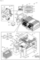
- Fig. 1 is a schematic explanatory diagram illustrating an example of mounting system 10 including printing device 11 constituting an example of the present disclosure and printing system 12.
- Fig. 2 is a schematic explanatory diagram of printing device 11, frame exchanging unit 40, and accommodation rack 50.
- Fig. 3 is a block diagram showing an electrical connection relationship of mounting system 10.
- Mounting system 10 is a system for mounting, for example, a component on board S as a processing target.
- Mounting system 10 includes printing device 11, mounting device 13, automatic conveyance vehicle 18, and management computer (PC) 60.
- Mounting system 10 is configured as a mounting line in which multiple mounting devices 13 for mounting a component on board S are arranged on a downstream side of printing device 11.
- Mounting device 13 is a device for mounting a component on board S on which a viscous fluid such as a solder paste or the like is printed by printing device 11.
- Automatic conveyance vehicle 18 moves between warehouse area 15 for storing and preparing for use a member for use in a mounting process and the mounting line, and automatically conveys accommodation rack 50 accommodating, for example, members such as screen masks M.
- Frame exchanging unit 40 for receiving accommodation rack 50 is connected to printing device 11, and automatic conveyance vehicle 18 transfers accommodation rack 50 that has been conveyed thereby to frame exchanging unit 40.
- This automatic conveyance vehicle 18 may be AGV configured to move along a line formed on a floor surface or AMR configured to travel autonomously based on a signal obtained from a sensor, a camera, or the like.
- Automatic conveyance vehicle 18 includes a controller, a driving section, a communication section, and a placement section. The controller controls the whole of the device.
- the driving section is a motor for rotationally driving wheels, and is controlled by the controller.
- the communication section is a wireless interface configured to communicate with an external device such as printing device 11 or management PC 60.
- Automatic conveyance vehicle 18 transmits and receives commands and signals to and from management PC 60 and printing device 11 via this communication section.
- Automatic conveyance vehicle 18 has the placement section for placing a member such as accommodation rack 50 on an upper surface thereof. This automatic conveyance vehicle 18 enters lifting and lowering space 48 defined in the center of frame exchanging unit 40 to receive and transfer accommodation rack 50 from and to frame exchanging unit 40.
- printing device 11 is a device for pushing a solder as a viscous fluid placed on screen mask M using squeegees 25 into a pattern hole formed in the screen mask M in question to thereby apply (print) the solder to board S as a processing target which lies below that screen mask M via the pattern hole.
- processing target there are raised, for example, board S on which a component is to be mounted, a substrate which is a three-dimensional object, and the like.
- viscous fluid there are raised a solder paste or a conductive paste, an adhesive, and the like.
- Print device 11 includes printing control section 21, printing section 22, mask work section 26, board processing section 30, cleaning section 33, supply section 35, and frame exchanging unit 40.
- Printing control section 21 is configured as a microprocessor mainly including CPU, and controls the whole of printing device 11.
- Printing control section 21 outputs a signal to management PC 60 as an external device, printing section 22, mask work section 26, board processing section 30, cleaning section 33, supply section 35, and frame exchanging unit 40 and receives signals from these sections as inputs therefrom.
- printing control section 21 outputs request information for requesting the movement of accommodation rack 50 to management PC 60 as a management device in accordance with a use state of exchangeable members in printing section 22.
- printing control section 21 receives a receipt signal notifying that accommodation rack 50 has been installed in frame exchanging unit 40 from automatic conveyance vehicle 18 as an input therefrom.
- printing control section 21 causes exchanging section 27 to exchange screen masks M between accommodation rack 50 and printing section 22.
- This printing control section 21 has a storage section where to store information on board S on which a printing process is executed, a printing process program for executing a printing process on board S, a member exchanging process program for executing an exchanging process of frames 29 by exchanging section 27, and the like.
- Printing section 22 is a unit installed at an upper stage of printing device 11 and configured to execute a printing process of printing a viscous fluid on board S using screen mask M. As shown in Figs. 1 and 4 , printing section 22 includes printing head 23, print moving section 24, a squeegee lifting and lowering section, and squeegees 25.
- Print moving section 24 moves printing head 23 in a predetermined printing direction (here, the front-rear direction), and includes a guide formed in the front-rear direction, a slider configured to move along the guide, and a motor for driving the slider.
- Squeegee 25 is installed on a lower surface side of printing head 23 and is lifted and lowered by the squeegee lifting and lowering section.
- Printing section 22 has two squeegees 25 which are both used in the front-rear direction.
- Mask work section 26 is a unit installed between printing section 22 and board processing section 30 in the up-down direction as shown in Fig. 2 and configured to fixedly hold screen mask M.
- mask work section 26 includes exchanging section 27 and mask fixing section 28.
- Exchanging section 27 is a conveyance rod provided on printing head 23 and is lowered to a position where it is brought into abutment with screen mask M by an air cylinder, not shown, and an abutting section thereof configured to be brought into abutment with frame 29 moves also in the front-rear direction as a result of being rotated (refer to dashed lines in Fig. 2 ).
- Printing head 23 and exchanging section 27 are brought into engagement with frame 29 between shelf section 51 in accommodation rack 50 which is positioned at a predetermined height and printing section 22 so as to move frame 29.
- Mask fixing section 28 positions and fixedly supports screen mask M in a horizontal posture. Screen mask M is pushed by exchanging section 27 so as to be moved in the front-rear direction along the guide of mask work section 26 and is fixed in place by mask fixing section 28.
- board processing section 30 is a unit installed below mask work section 26 and configured to convey in board S, position conveyed board S in for support, and move that board S towards screen mask M for contact and away from the screen mask M.
- Board processing section 30 includes board conveyance section 31 for conveying board S in the left-right direction, support member 32 for supporting board S from below, and a board lifting and lowering section for lifting and lowering the whole of board processing section 30 and support member 32.
- Cleaning section 33 is a unit installed between mask work section 26 and board processing section 30 in the up-down direction and configured to execute a cleaning process of cleaning a rear face of screen mask M.
- Cleaning section 33 has cleaning member 34 and cleans screen mask M with cleaning member 34.
- Supply section 35 is a unit for supplying a solder accommodated in cartridge 36 on to screen mask M.
- Supply section 35 is installed ahead of printing head 23.
- Supply section 35 applies a pressure to cartridge 36 so as to discharge the solder from cartridge 36.
- Cleaning member 34 and cartridge 36 are consumables and are exchanged as required.
- Frame exchanging unit 40 is configured as a device for receiving accommodation rack 50 accommodating exchangeable members such as screen mask M fixed to frame 29 and lifting and lowering accommodation rack 50.
- Frame exchanging unit 40 includes left unit 41 and right unit 45 which function as the lifting and lowering section of the present disclosure.
- left unit 41 and right unit 45 have receiving section 42 and receiving section 46, respectively, where accommodation rack 50 is received.
- Left unit 41 is installed at a front left side of a housing of printing device 11.
- Right unit 45 is installed at a front right side of the housing of printing device 11.
- These left unit 41 and right unit 45 are formed such that length A along a movement direction of frame 29 is shorter than length B of accommodation rack 50 (refer to Fig. 2 ).
- Accommodation rack 50 is an accommodation body for accommodating frames 29 which can support screen masks M as exchangeable members for a printing process that is executed at printing section 22.
- This accommodation rack 50 has multiple shelf sections 51 and one opening section 52. Shelf sections 51 are installed in such a manner as to be aligned at predetermined intervals in the up-down direction so as to enable frames 29 supporting screen mask M to be placed thereon in the up-down direction.
- opening section 52 communicates with an outside such as printing section 22, and frame 29 is conveyed in and out through opening section 52.
- Accommodation rack 50 has no driving section for moving frame 29. With this accommodation rack 50, the configuration can be simplified more. Shelf section 51 has a size which can correspond to sizes of frames for exchangeable members of various types.
- shelf section 51 is formed in a size capable of accommodating largest frame 29.
- This accommodation rack 50 may be accommodation rack 50 having shelf sections 51 corresponding individually to sizes of frames for exchangeable members of various types or may be accommodation rack 50 having multiple shelf sections 51 all having the same size.
- multiple accommodation racks 50 having the same external size may be prepared, so that shelf sections 51 of each accommodation rack 50 correspond to any one of sizes of frames for exchangeable members of various types.
- the number of types of accommodation rack 50 increases, since the external sizes of multiple accommodation racks 50 are the same, even in the case that sizes of frames for exchangeable members which are dealt with differ, multiple accommodation racks 50 in question can share receiving portions 42, 46.
- Management PC 60 is a device for managing information on the individual constituent devices of mounting system 10.
- This management PC 60 includes management control section 61, storage section 62, and communication section 63.
- Management control section 61 is configured as a microprocessor mainly including CPU, and controls the whole of the device. Upon acquisition of request information for requesting the movement of accommodation rack 50 from printing device 11, management control section 61 outputs a command to cause automatic conveyance vehicle 18 for conveying accommodation rack 50 to move accommodation rack 50 to the control PC or automatic conveyance vehicle 18 in warehouse area 15.
- Storage section 62 is a large-capacity storage medium such as HDD or a flash memory, and manages the progress status of each device on the mounting line, a member which is being conveyed by automatic conveyance vehicle 18 or the current position of automatic conveyance vehicle 18, and the like.
- Communication section 63 is an interface for use in communication with an external device. Each device of mounting system 10 exchanges information with management PC 60 via communication section 63.
- a printing process routine for executing a printing process is stored in the storage section of printing control section 21 and is executed after printing control section 21 receives an execution command to execute a printing process as an input from the operator.
- the CPU of printing control section 21 first causes board processing section 30 to convey, fix and lift board S to thereby execute a process of bringing that board S into abutment with screen mask S.
- the CPU causes mask work section 26 to adjust the position of screen mask M for a position alignment between a pattern hole and board S.
- the CPU moves cartridge 36 to above screen mask M and then causes the cartridge 36 to discharge the solder stored therein.
- the CPU not only moves printing head 23 but also lowers squeegees 25 so as to bring squeegees 25 into abutment with an upper surface of the screen mask M and then moves squeegees 25 in the front-rear direction so as to apply the solder on to board S.
- printing control section 21 executes the printing process including the board conveyance and fixation process, the solder supply process, and the squeegee moving process to thereby execute printing on board S.
- the CPU repeatedly executes this printing process while exchanging screen masks M until the production process of producing all types of boards S described in a production plan is completed.
- the CPU determines that it is a moving timing of accommodation rack 50 when accommodation rack 50 is moved from warehouse area 15 to frame exchanging unit 40, for example, in such a state that no accommodation rack 50 is installed in frame exchanging unit 40 or when accommodation rack 50 is moved from frame exchanging unit 40 to warehouse area 15, for example, in such a state that all screen masks M accommodated in that accommodation rack 50 have been used up.
- the CPU determines that it is a moving timing of accommodation rack 50
- the CPU outputs request information for requesting the movement of accommodation rack 50 to management PC 60 (S 110).
- management PC 60 Upon acquisition of the request information, management PC 60 transmits a command to move accommodation rack 50 to the control PC or automatic conveyance vehicle 18 in warehouse area 15. In response to the request, automatic conveyance vehicle 18 moves accommodation rack 50 between accommodation rack 50 and warehouse area 15.
- the CPU determines whether a receiving process in which frame exchanging unit 40 receives accommodation rack 50 from automatic conveyance vehicle 18 is to be executed (S120). The CPU determines that the receiving process is to be executed when no accommodation rack 50 exists in frame exchanging unit 40 and after request information is outputted. On the other hand, the CPU determines that the receiving process is not to be executed when accommodation rack 50 exists in frame exchanging unit 40. For execution of the receiving process, the CPU drives driving sections 43, 47 so as to move receiving sections 42, 46 to the lowermost portions respectively (S130).
- automatic conveyance vehicle 18 moves to the front of frame exchanging unit 40 with accommodation rack 50 placed thereon, automatic conveyance vehicle 18 inserts accommodation rack 50 in lifting and lowering space 48 and transmits a receipt signal to printing control section 21.
- the CPU determines that accommodation rack 50 exists in a receiving position in frame exchanging unit 40 and causes receiving sections 42, 46 to be lifted, so that accommodation rack 50 is received in frame exchanging unit 40 (S140).
- the CPU may be configured to specify accommodation rack 50 received in frame exchanging unit 40 by reading an identifier affixed to accommodation rack 50 so received by a reading section not shown.
- Fig. 5 is an explanatory diagram showing an example of receiving accommodation rack 50 by frame exchanging unit 40, in which Fig. 5A is a diagram showing a state in which accommodation rack 50 is waiting to be received (S130), Fig. 5B is a diagram showing a state in which accommodation rack 50 is inserted into lifting and lowering space 48, and Fig. 5C is a diagram showing a state in which accommodation rack 50 is received accordingly (S140).
- Printing device 11 causes receiving sections 42, 46 of frame exchanging unit 40 to move to the lowermost portions ( Fig. 5A ), and causes receiving sections 42, 46 to be lifted up when automatic conveyance vehicle 18 inserts accommodation rack 50 into lifting and lowering space 48 ( Fig. 5B ) to thereby receive accommodation rack 50 ( Fig. 5C ). In this way, printing device 11 receives accommodation rack 50.
- the CPU determines whether a transfer process of transferring accommodation rack 50 from frame exchanging unit 40 to automatic conveyance vehicle 18 is to be executed (S150). The CPU determines that the transfer process is to be executed when accommodation rack 50 accommodating only screen masks M that have been used up exists in frame exchanging unit 40. On the other hand, the CPU determines that no transfer process is to be executed when accommodation rack 50 staying in frame exchanging unit 40 accommodates frames 29 for use for a subsequent printing process or when no accommodation rack 50 exists in frame exchanging unit 40.
- the CPU waits until it receives a transfer signal from automatic conveyance vehicle 18, and upon receipt of a transfer signal, determining that automatic conveyance vehicle 18 arrives at lifting and lowering space 48, the CPU drives driving sections 43, 47 so as to cause them to move corresponding receiving sections 42, 46 to the lowermost portions, causing accommodation rack 50 to be transferred from frame exchanging unit 40 to automatic conveyance vehicle 18 (S160).
- Automatic conveyance vehicle 18 then moves accommodation rack 50 placed thereon to warehouse area 15.
- printing device 11 waits for automatic conveyance vehicle 18 to arrive ( Fig. 5C ), moves receiving sections 42, 46 of frame exchanging unit 40 to the lowermost portions ( Fig. 5A ) when automatic conveyance vehicle 18 enters lifting and lowering space 48 ( Fig. 5B ), and transfers accommodation rack 50 to automatic conveyance vehicle 18.
- Fig. 6 is an explanatory diagram illustrating an example of exchanging screen masks M between printing section 22 and accommodation rack 50, in which Fig. 6A is a diagram showing a state in which frames 29 are transferred out into vacant shelf sections 51, Fig. 6B is a diagram showing a state in which frames 29 are inserted into shelf sections 51, and Fig.
- the CPU drives driving sections 43, 47 so as to cause them to lift up or lower accommodation rack 50 to position shelf section 51 installing screen mask M for a subsequent use in an exchanging position at a predetermined height (S200). Then, the CPU executes a convey-in process of moving screen mask M residing in shelf section 51 into printing section 22 (S210).
- the CPU lowers and rotates the abutting section of exchanging section 27 so that the abutting section comes into engagement with an edge portion of frame 29, causes print moving section 24 to move printing head 23 to the rear, and causes that frame 29 to move into printing section 22 by, for example, rotating exchanging section 27 ( Fig. 6C ).
- the CPU may be configured to specify screen mask M conveyed into printing section 22 by reading an identifier affixed to frame 29 by a reading section not shown.
- the CPU determines whether all printing processes of printing device 11 have been completed (S220), and if the CPU determines that the printing processes have not yet been completed, the CPU executes the processing from S100 onward. On the other hand, if the CPU determines in S220 that all the printing processes have been completed, the routine ends.
- Printing section 22 of the present embodiment corresponds to a printing section
- receiving sections 42, 46 correspond to a receiving section
- left unit 41 and right unit 45 correspond to a lifting and lowering section
- exchanging section 27 corresponds to an exchanging section
- printing control section 21 corresponds to a printing control section.
- printing system 12 corresponds to a printing system
- frame exchanging unit 40 corresponds to a frame exchanging unit
- management PC 60 corresponds to a management device
- management control section 61 corresponds to a management control section.
- Printing device 11 of the present embodiment includes printing section 22 configured to execute the printing process of the solder paste as the viscous fluid on board S as the processing target using screen mask M as the exchangeable member for use in the printing process executed in printing section 22, and receiving sections 42, 46 configured to receive accommodation rack 50 having multiple shelf sections 51 accommodating frames 29 configured to support screen masks M.
- Fig. 8 is an explanatory diagram illustrating an example of printing device 110 including storage device 140.
- Printing device 110 is configured such that storage device 140 is configured to accommodate multiple exchangeable members and that frames 29 to which exchangeable members are fixed are conveyed into storage device 140 from automatic conveyance vehicle 18 or printing section 22 and are conveyed out from storage device 140 on to automatic conveyance vehicle 18 or printing section 22.
- Storage device 140 has a moving mechanism for moving frames 29 and a lifting and lowering mechanism for moving shelf sections 51 vertically.
- this printing device 110 in the case that automatic conveyance vehicle 18 conveys exchangeable members for exchange of exchangeable members to and from printing section 22, there are needed at least two spaces of a space for frame 29 to be separated apart from automatic conveyance vehicle 18 completely and a space for frame 29 to be separated apart from storage device 140 completely, and hence, the space efficiency is not good.
- exchangeable members are exchanged while adjusting the vertical position by storage device 140, resulting in, for example, a problem in that much time is needed for exchange.
- printing device 11 since printing device 11 includes left unit 41 and right unit 45 which function as the lifting and lowering section for lifting and lowering accommodation rack 50, exchangeable members can be exchanged by lifting up and lowering entire accommodation rack 50 by means of the lifting and lowering section. Further, in printing device 11, the lifting and lowering section is formed such that length A along the movement direction is shorter than length B of accommodation rack 50. With this printing device 11, the size of the device can be made more compact with accommodation rack 50 detached. In addition, with printing device 11, the lifting and lowering section includes left unit 41 installed on the left side of the housing and right unit 45 installed on the right side of the housing of printing device 11, and lifting and lowering space 48 where accommodation rack 50 is lifted up and lowered is provided in the center of the lifting and lowering section. With this printing device 11, since accommodation rack 50 is inserted into lifting and lowering space 48 defined between the lifting and lowering sections for exchange of accommodation racks 50, the exchange of accommodation racks 50 is facilitated.
- Printing device 11 includes exchanging section 27 for moving frame 29 between shelf section 51 of accommodation rack 50 which is positioned at the predetermined height and printing section 22. With this printing device 11, exchangeable members can be exchanged by exchanging section 27. With printing device 11, since exchanging section 27 constitutes a mechanism configured to be brought into engagement with frame 29 so as to move an exchangeable member, printing device 11 can be configured relatively simple.
- printing device 11 includes exchanging section 27 for moving frame 29 between shelf section 51 of accommodation rack 50 which is positioned at the predetermined height and printing section 22 and printing control section 21 for controlling printing section 22 and exchanging section 27.
- exchanging section 27 for moving frame 29 between shelf section 51 of accommodation rack 50 which is positioned at the predetermined height and printing section 22 and printing control section 21 for controlling printing section 22 and exchanging section 27.
- Printing device 11 includes the lifting and lowering sections for lifting and lowering accommodation rack 50, and exchanging section 27 for moving frame 29, and when there exists frame 29 supporting used screen mask M in printing section 22, printing control section 21 causes the lifting and lowering sections and the exchanging section 27 to lift up or lower accommodation rack 50, to move frame 29 supporting the used screen mask M into vacant shelf section 51 of accommodation rack 50, and to move frame 29 supporting screen mask M for a subsequent use into printing section 22.
- printing control section 21 outputs request information for requesting the movement of accommodation rack 50 in accordance with the use state of exchangeable members at printing section 22 to management PC 60 as the management device for managing printing device 11.
- the exchange of accommodation racks 50 can be executed more smoothly via management PC 60.
- Accommodation rack 50 has multiple shelf sections 51 configured to install frames 29 supporting an exchangeable member in such a manner as to be placed in the up-down direction and opening section 52 which communicates with printing section 22.
- exchangeable members can be exchanged more efficiently via opening section 52 by receiving accommodation rack 50 accommodating exchangeable members in the up-down direction using shelf sections 51 into printing device 11.
- accommodation rack 50 has no driving section, the configuration of the device can be simplified more.
- printing device 11 since accommodation rack 50 has shelf sections 51 corresponding to frames of various sizes for various types of exchangeable members, printing device 11 can deal with various types of exchangeable members while reducing the number of types of accommodation racks 50 by using single-type general purpose accommodation rack 50.
- Frame exchanging unit 40 is provided on printing device 11 including printing section 22 for executing the printing process of the viscous fluid on board S as the processing target using screen mask M, and has the lifting and lowering sections for lifting and lowering accommodation rack 50 having multiple shelf sections 51 accommodating frames 29 configured to support exchangeable members for use in printing device 11. With this frame exchanging unit 40, exchangeable members can be exchanged by lifting and lowering entire accommodation rack 50 by the lifting and lowering sections, and therefore exchangeable members can be exchanged more efficiently.
- the storage device and the printing system of the present disclosure are not limited to those described in the embodiment at all, and hence, it goes without saying that the accommodation device and the printing system can be executed in various forms without departing from the scope of the present disclosure.
- printing device 11 is described as including frame exchanging unit 40 having the lifting and lowering sections; however, as long as printing device 11 includes a receiving section for receiving accommodation rack 50, printing device 11 need not have the lifting and lowering sections.
- printing device 11 is described as having exchanging section 27; however, exchanging section 27 may be omitted.
- printing device 11 is described as having printing control section 21; however, printing control section 21 may be omitted.
- frame exchanging unit 40 is described as being formed such that length A along the movement direction of frame 29 is shorter than length B of accommodation rack 50; however, the present invention is not particularly limited thereto.
- frame exchanging unit 40 is preferably configured such that length A is shorter than length B, whereby the device can be made compact in size.
- frame exchanging unit 40 is described as including left unit 41 and right unit 45 so that the main bodies of frame exchanging unit 40 are disposed individually at the left and right of the housing of printing device 11; however, the present invention is not limited thereto, and hence, as long as a space for accommodating accommodation rack 50 is provided, frame exchanging unit 40 may be formed into an integrated structure.
- frame exchanging unit 40 is described as being installed ahead of printing device 11; however, the present invention is not particularly limited thereto, and hence, frame exchanging unit 40 may be installed to the rear or side of printing device 11.
- receiving sections 42, 46 are described as receiving accommodation rack 50 by supporting the left and right end portions of accommodation rack 50 from the lower surface side; however, the present invention is not particularly limited thereto as long as accommodation rack 50 can be received accordingly, and hence, for example, receiving sections 42, 46 may be configured to support the whole of a lower surface of accommodation rack 50, or may be configured to receive accommodation rack 50 by supporting accommodation rack 50 from side surfaces or an upper surface of accommodation rack 50.
- frame exchanging unit 40 is described as receiving accommodation rack 50 from automatic conveyance vehicle 18 by lifting up accommodation rack 50 upwards and transferring accommodation rack 50 to automatic conveyance vehicle 18 by lowering accommodation rack 50 downwards; however, the present invention is not particularly limited thereto as long as accommodation rack 50 can be received and transferred accordingly.
- exchanging section 27 is described as being made into the rod structure installed on printing head 23 and having the abutting section; however, the present invention is not particularly limited thereto, and hence exchanging section 27 may be an independent mechanism installed on parts other than printing head 23.
- exchanging section 27 is described as being made into the rod mechanism configured to be brought into engagement with frame 29; however, exchanging section 27 may be made into, for example, a conveyor mechanism for moving frame 29 including an exchangeable member with frame 29 placed thereon.
- printing control section 21 is described as outputting request information to management PC 60; however, the present invention is not limited thereto, and hence, this process may be omitted.
- management control section 61 is described as outputting the command to move accommodation rack 50 to warehouse area 15 or automatic conveyance vehicle 18 when it acquires request information; however, this process may be omitted.
- management control section 61 may be configured to output a movement instruction to the control PC in warehouse area 15 for display thereon.
- mounting system 10 is described as having automatic conveyance vehicle 18; however, the present invention is not particularly limited thereto, and hence, the operator may convey accommodation rack 50 with automatic conveyance vehicle 18 omitted.
- warehouse area 15 is described as having arm robot 16 and the control PC; however, either of arm robot 16 and the control PC may be omitted.
- accommodation rack 50 is described as including shelf sections 51 configured to accommodate frame 29 for placement therein; however, the present invention is not particularly limited thereto as long as accommodation rack 50 can accommodate multiple frames 29.
- Fig. 7 is an explanatory diagram showing an example of another type of accommodation rack 50B.
- This accommodation rack 50B includes shelf sections 51B provided on the left and right of an interior thereof so as to receive and support end portions of frame 29 inserted. With this accommodation rack 50B, the shelf sections 51 can be simplified more.
- accommodation rack 50 is described as having no driving section for moving frame 29; however, the present invention is not particularly limited thereto, and hence, accommodation rack 50 may have a driving section for moving frame 29.
- the present disclosure is applicable to the technical field of devices for use for a component mounting process.
Landscapes
- Engineering & Computer Science (AREA)
- Mechanical Engineering (AREA)
- Warehouses Or Storage Devices (AREA)
- Electric Connection Of Electric Components To Printed Circuits (AREA)
- Screen Printers (AREA)
Abstract
Description
- The present description discloses a printing device, a printing system, and a frame exchanging unit.
- Conventionally, there has been known, for example, a printing device for executing a printing process of a viscous fluid on a printing target such as a board using a screen mask in which exchangeable members for use in the printing device including screen masks is automatically exchanged. For example, Patent Literature 1 describes a printing device in which a printing device is installed in front of another printing device for an automatic exchange of exchangeable members between the printing device and the printing device.
- Patent Literature 1: International Publication
2018/105016 - In the printing device described above, however, for example, in the case that an automatic conveyance vehicle conveys exchangeable members such as screen masks for exchange of the exchangeable members at the printing device, there are needed at least two spaces of a space for complete separation of an exchangeable member from the automatic conveyance vehicle and a space for complete separation of an exchangeable member from an accommodation device, and the exchange is executed while adjusting the vertical position of the accommodating device, causing a problem in that much time is needed for the exchange.
- The present disclosure has been made in view of the problem described above, and a main object of the present disclosure is to provide a printing device, a printing system, and a frame exchanging unit for exchanging exchangeable members for use in the printing device with good efficiency.
- A printing device, a printing system, and a frame exchanging unit disclosed in the present description take the following means with a view to attaining the main object.
- A printing device of the present disclosure includes:
- a printing section configured to execute a printing process of a viscous fluid on a processing target using a screen mask; and
- a receiving section configured to receive an accommodation rack having multiple shelf sections for accommodating frames configured to support exchangeable members for a printing process that is executed at the printing section.
- In this printing device, the accommodation rack is received which has the multiple shelf sections for accommodating the frames configured to support the exchangeable members for the printing process executed at the printing section. With this printing device, since the accommodation rack accommodating the multiple exchangeable members can be exchanged altogether, the exchangeable members can be exchanged more efficiently.
-
-
Fig. 1 is a schematic explanatory diagram illustrating an example ofmounting system 10 andprinting system 12. -
Fig. 2 is a schematic explanatory diagram ofprinting device 11,frame exchanging unit 40, andaccommodation rack 50. -
Fig. 3 is a block diagram showing an electrical connection relationship ofmounting system 10. -
Fig. 4 is a flowchart showing an example of a member exchanging process routine. -
Fig. 5 is an explanatory diagram illustrating receipt ofaccommodation rack 50 byframe exchanging unit 40. -
Fig. 6 is an explanatory diagram illustrating an example of exchange of screen masks M. -
Fig. 7 is an explanatory diagram illustrating an example of anotheraccommodation rack 50B. -
Fig. 8 is an explanatory diagram illustrating an example ofprinting device 110 includingstorage device 140. - Hereinafter, the present embodiment will be described while referring to drawings.
Fig. 1 is a schematic explanatory diagram illustrating an example ofmounting system 10 includingprinting device 11 constituting an example of the present disclosure andprinting system 12.Fig. 2 is a schematic explanatory diagram ofprinting device 11,frame exchanging unit 40, andaccommodation rack 50.Fig. 3 is a block diagram showing an electrical connection relationship ofmounting system 10.Mounting system 10 is a system for mounting, for example, a component on board S as a processing target.Mounting system 10 includesprinting device 11,mounting device 13,automatic conveyance vehicle 18, and management computer (PC) 60.Mounting system 10 is configured as a mounting line in whichmultiple mounting devices 13 for mounting a component on board S are arranged on a downstream side ofprinting device 11.Printing system 12 includesprinting device 11 and management PC 60 functioning mainly to manageprinting device 11. Here, in the present embodiment, a left-right direction (an X axis), front-rear direction (a Y axis), and an up-down direction (a Z axis) are as shown inFigs. 1 ,2 ,5 , and6 . -
Warehouse area 15 is an area for preparing an exchangeable member (hereinafter, also simply referred to as a member) or the like for use inmounting system 10. There are raised as a member for use inmounting system 10, for example, inprinting device 11, screen mask M,support member 32 for fixing a processing target, squeegee 25 for applying a solder paste as a viscous fluid in a printing process,cartridge 36 for accommodating a viscous fluid, cleaningmember 34 for cleaning screen mask M, and the like.Arm robot 16 and preparation table 17 are disposed in thiswarehouse area 15.Arm robot 16 performs an operation of placingaccommodation rack 50 prepared for subsequent use from preparation table 17 toautomatic conveyance vehicle 18, and an operation of moving usedaccommodation rack 50 collected byautomatic conveyance vehicle 18 to preparation table 17. Preparation table 17 is a working table on which new accommodation rack 50 and usedaccommodation rack 50 are placed.Arm robot 16 is controlled by a control PC, not shown. This control PC receives an exchange command from management PC 60 via a network line, and outputs information on a work status ofarm robot 16 to management PC 60. Inwarehouse area 15, an operator may move and prepareaccommodation rack 50. -
Mounting device 13 is a device for mounting a component on board S on which a viscous fluid such as a solder paste or the like is printed byprinting device 11. -
Automatic conveyance vehicle 18 moves betweenwarehouse area 15 for storing and preparing for use a member for use in a mounting process and the mounting line, and automatically conveysaccommodation rack 50 accommodating, for example, members such as screen masks M.Frame exchanging unit 40 for receivingaccommodation rack 50 is connected toprinting device 11, andautomatic conveyance vehicle 18transfers accommodation rack 50 that has been conveyed thereby to frame exchangingunit 40. Thisautomatic conveyance vehicle 18 may be AGV configured to move along a line formed on a floor surface or AMR configured to travel autonomously based on a signal obtained from a sensor, a camera, or the like.Automatic conveyance vehicle 18 includes a controller, a driving section, a communication section, and a placement section. The controller controls the whole of the device. The driving section is a motor for rotationally driving wheels, and is controlled by the controller. The communication section is a wireless interface configured to communicate with an external device such asprinting device 11 or management PC 60.Automatic conveyance vehicle 18 transmits and receives commands and signals to and from management PC 60 andprinting device 11 via this communication section.Automatic conveyance vehicle 18 has the placement section for placing a member such asaccommodation rack 50 on an upper surface thereof. Thisautomatic conveyance vehicle 18 enters lifting and loweringspace 48 defined in the center offrame exchanging unit 40 to receive and transferaccommodation rack 50 from and toframe exchanging unit 40. - As shown in
Figs. 1 to 3 ,printing device 11 is a device for pushing a solder as a viscous fluid placed on screen maskM using squeegees 25 into a pattern hole formed in the screen mask M in question to thereby apply (print) the solder to board S as a processing target which lies below that screen mask M via the pattern hole. Here, as the "processing target", there are raised, for example, board S on which a component is to be mounted, a substrate which is a three-dimensional object, and the like. As the "viscous fluid", there are raised a solder paste or a conductive paste, an adhesive, and the like. Here, the following description will be made based on the understanding that the processing target is board S and the viscous fluid is solder. Screen mask M is fixed to an inner side offrame 29.Frame 29 is such that several kinds or sizes of screen masks M can be fixed thereto and is sized to be accommodated inshelf section 51 of accommodation rack 50 (refer toFig. 1 ). As shown inFig. 3 ,printing device 11 includesprinting control section 21,printing section 22,mask work section 26,board processing section 30,cleaning section 33,supply section 35, andframe exchanging unit 40. -
Printing control section 21 is configured as a microprocessor mainly including CPU, and controls the whole ofprinting device 11.Printing control section 21 outputs a signal tomanagement PC 60 as an external device,printing section 22,mask work section 26,board processing section 30,cleaning section 33,supply section 35, andframe exchanging unit 40 and receives signals from these sections as inputs therefrom. For example,printing control section 21 outputs request information for requesting the movement ofaccommodation rack 50 to management PC 60 as a management device in accordance with a use state of exchangeable members inprinting section 22. In addition,printing control section 21 receives a receipt signal notifying thataccommodation rack 50 has been installed inframe exchanging unit 40 fromautomatic conveyance vehicle 18 as an input therefrom. Further,printing control section 21causes exchanging section 27 to exchange screen masks M betweenaccommodation rack 50 andprinting section 22. Thisprinting control section 21 has a storage section where to store information on board S on which a printing process is executed, a printing process program for executing a printing process on board S, a member exchanging process program for executing an exchanging process offrames 29 by exchangingsection 27, and the like. -
Printing section 22 is a unit installed at an upper stage ofprinting device 11 and configured to execute a printing process of printing a viscous fluid on board S using screen mask M. As shown inFigs. 1 and4 , printingsection 22 includesprinting head 23,print moving section 24, a squeegee lifting and lowering section, and squeegees 25.Print moving section 24moves printing head 23 in a predetermined printing direction (here, the front-rear direction), and includes a guide formed in the front-rear direction, a slider configured to move along the guide, and a motor for driving the slider.Squeegee 25 is installed on a lower surface side ofprinting head 23 and is lifted and lowered by the squeegee lifting and lowering section.Printing section 22 has twosqueegees 25 which are both used in the front-rear direction.Mask work section 26 is a unit installed betweenprinting section 22 andboard processing section 30 in the up-down direction as shown inFig. 2 and configured to fixedly hold screen mask M. As shown inFig. 3 ,mask work section 26 includes exchangingsection 27 andmask fixing section 28. Exchangingsection 27 is a conveyance rod provided onprinting head 23 and is lowered to a position where it is brought into abutment with screen mask M by an air cylinder, not shown, and an abutting section thereof configured to be brought into abutment withframe 29 moves also in the front-rear direction as a result of being rotated (refer to dashed lines inFig. 2 ).Printing head 23 and exchangingsection 27 are brought into engagement withframe 29 betweenshelf section 51 inaccommodation rack 50 which is positioned at a predetermined height andprinting section 22 so as to moveframe 29. Mask fixingsection 28 positions and fixedly supports screen mask M in a horizontal posture. Screen mask M is pushed by exchangingsection 27 so as to be moved in the front-rear direction along the guide ofmask work section 26 and is fixed in place bymask fixing section 28. As shown inFig. 2 ,board processing section 30 is a unit installed belowmask work section 26 and configured to convey in board S, position conveyed board S in for support, and move that board S towards screen mask M for contact and away from the screen mask M.Board processing section 30 includesboard conveyance section 31 for conveying board S in the left-right direction,support member 32 for supporting board S from below, and a board lifting and lowering section for lifting and lowering the whole ofboard processing section 30 andsupport member 32.Cleaning section 33 is a unit installed betweenmask work section 26 andboard processing section 30 in the up-down direction and configured to execute a cleaning process of cleaning a rear face of screen maskM. Cleaning section 33 has cleaningmember 34 and cleans screen mask M with cleaningmember 34.Supply section 35 is a unit for supplying a solder accommodated incartridge 36 on to screen maskM. Supply section 35 is installed ahead of printinghead 23.Supply section 35 applies a pressure tocartridge 36 so as to discharge the solder fromcartridge 36.Cleaning member 34 andcartridge 36 are consumables and are exchanged as required. -
Frame exchanging unit 40 is configured as a device for receivingaccommodation rack 50 accommodating exchangeable members such as screen mask M fixed to frame 29 and lifting and loweringaccommodation rack 50.Frame exchanging unit 40 includes leftunit 41 andright unit 45 which function as the lifting and lowering section of the present disclosure. In addition, leftunit 41 andright unit 45 have receivingsection 42 and receivingsection 46, respectively, whereaccommodation rack 50 is received.Left unit 41 is installed at a front left side of a housing ofprinting device 11.Right unit 45 is installed at a front right side of the housing ofprinting device 11. Theseleft unit 41 andright unit 45 are formed such that length A along a movement direction offrame 29 is shorter than length B of accommodation rack 50 (refer toFig. 2 ). Thisframe exchanging unit 40 has lifting and loweringspace 48 where to lift andlower accommodation rack 50 in the center betweenleft unit 41 andright unit 45.Left unit 41 includes receivingsection 42 and drivingsection 43.Right unit 45 includes receivingsection 46 and drivingsection 47. Receivingsection 42 receivesaccommodation rack 50accommodating frames 29 for supporting screen masks M and supports thisaccommodation rack 50 from a lower surface side thereof. Receivingsection 42 may fixaccommodation rack 50 by means of, for example, a magnetic force or the like. Drivingsection 43 is configured to lift andlower accommodation rack 50 by lifting and lowering receivingsection 42. This drivingsection 43 may be such as to have a ball screw having a lifting and lowering shaft and a driving motor or may be a linear motor. Here, since receivingsection 46 and drivingsection 47 are the same as receivingsection 42 and drivingsection 43, the description thereof will be omitted. -
Accommodation rack 50 is an accommodation body for accommodatingframes 29 which can support screen masks M as exchangeable members for a printing process that is executed atprinting section 22. Thisaccommodation rack 50 hasmultiple shelf sections 51 and oneopening section 52.Shelf sections 51 are installed in such a manner as to be aligned at predetermined intervals in the up-down direction so as to enableframes 29 supporting screen mask M to be placed thereon in the up-down direction. In addition, openingsection 52 communicates with an outside such asprinting section 22, andframe 29 is conveyed in and out throughopening section 52.Accommodation rack 50 has no driving section for movingframe 29. With thisaccommodation rack 50, the configuration can be simplified more.Shelf section 51 has a size which can correspond to sizes of frames for exchangeable members of various types. That is,shelf section 51 is formed in a size capable of accommodatinglargest frame 29. Thisaccommodation rack 50 may beaccommodation rack 50 havingshelf sections 51 corresponding individually to sizes of frames for exchangeable members of various types or may beaccommodation rack 50 havingmultiple shelf sections 51 all having the same size. In the case ofaccommodation rack 50 having the latter configuration,multiple accommodation racks 50 having the same external size may be prepared, so thatshelf sections 51 of eachaccommodation rack 50 correspond to any one of sizes of frames for exchangeable members of various types. In this case, although the number of types ofaccommodation rack 50 increases, since the external sizes ofmultiple accommodation racks 50 are the same, even in the case that sizes of frames for exchangeable members which are dealt with differ,multiple accommodation racks 50 in question can share receivingportions -
Management PC 60 is a device for managing information on the individual constituent devices of mountingsystem 10. Thismanagement PC 60 includesmanagement control section 61,storage section 62, andcommunication section 63.Management control section 61 is configured as a microprocessor mainly including CPU, and controls the whole of the device. Upon acquisition of request information for requesting the movement ofaccommodation rack 50 fromprinting device 11,management control section 61 outputs a command to causeautomatic conveyance vehicle 18 for conveyingaccommodation rack 50 to moveaccommodation rack 50 to the control PC orautomatic conveyance vehicle 18 inwarehouse area 15.Storage section 62 is a large-capacity storage medium such as HDD or a flash memory, and manages the progress status of each device on the mounting line, a member which is being conveyed byautomatic conveyance vehicle 18 or the current position ofautomatic conveyance vehicle 18, and the like.Communication section 63 is an interface for use in communication with an external device. Each device of mountingsystem 10 exchanges information withmanagement PC 60 viacommunication section 63. - Firstly, a printing process executed by printing
device 11 configured as described above will be described. A printing process routine for executing a printing process is stored in the storage section ofprinting control section 21 and is executed after printingcontrol section 21 receives an execution command to execute a printing process as an input from the operator. When the printing process routine is started, the CPU ofprinting control section 21 first causesboard processing section 30 to convey, fix and lift board S to thereby execute a process of bringing that board S into abutment with screen mask S. As this occurs, the CPU causesmask work section 26 to adjust the position of screen mask M for a position alignment between a pattern hole and board S. Subsequently, the CPU movescartridge 36 to above screen mask M and then causes thecartridge 36 to discharge the solder stored therein. Subsequently, the CPU not only movesprinting head 23 but also lowerssqueegees 25 so as to bringsqueegees 25 into abutment with an upper surface of the screen mask M and then movessqueegees 25 in the front-rear direction so as to apply the solder on to board S. In this way,printing control section 21 executes the printing process including the board conveyance and fixation process, the solder supply process, and the squeegee moving process to thereby execute printing on board S. The CPU repeatedly executes this printing process while exchanging screen masks M until the production process of producing all types of boards S described in a production plan is completed. - Next, operations performed by printing
device 11 forframe exchanging unit 40 will be described.Fig. 4 is a flowchart showing an example of a member exchanging process routine executed by printingcontrol section 21 ofprinting device 11. This routine is stored in the storage section ofprinting control section 21 and is executed after printingdevice 11 is activated. If this routine is executed, the CPU ofprinting control section 21 determines whether it is a moving timing of accommodation rack 50 (S100). The CPU determines that it is a moving timing ofaccommodation rack 50 whenaccommodation rack 50 is moved fromwarehouse area 15 to frame exchangingunit 40, for example, in such a state that noaccommodation rack 50 is installed inframe exchanging unit 40 or whenaccommodation rack 50 is moved fromframe exchanging unit 40 towarehouse area 15, for example, in such a state that all screen masks M accommodated in thataccommodation rack 50 have been used up. If the CPU determines that it is a moving timing ofaccommodation rack 50, the CPU outputs request information for requesting the movement ofaccommodation rack 50 to management PC 60 (S 110). Upon acquisition of the request information,management PC 60 transmits a command to moveaccommodation rack 50 to the control PC orautomatic conveyance vehicle 18 inwarehouse area 15. In response to the request,automatic conveyance vehicle 18 movesaccommodation rack 50 betweenaccommodation rack 50 andwarehouse area 15. - After S110 or if the CPU determines in S100 that it is not a moving timing of
accommodation rack 50, the CPU determines whether a receiving process in whichframe exchanging unit 40 receivesaccommodation rack 50 fromautomatic conveyance vehicle 18 is to be executed (S120). The CPU determines that the receiving process is to be executed when noaccommodation rack 50 exists inframe exchanging unit 40 and after request information is outputted. On the other hand, the CPU determines that the receiving process is not to be executed whenaccommodation rack 50 exists inframe exchanging unit 40. For execution of the receiving process, the CPU drives drivingsections sections automatic conveyance vehicle 18 moves to the front offrame exchanging unit 40 withaccommodation rack 50 placed thereon,automatic conveyance vehicle 18 insertsaccommodation rack 50 in lifting and loweringspace 48 and transmits a receipt signal toprinting control section 21. Upon acquisition of the receipt signal fromautomatic conveyance vehicle 18, the CPU determines thataccommodation rack 50 exists in a receiving position inframe exchanging unit 40 andcauses receiving sections accommodation rack 50 is received in frame exchanging unit 40 (S140). For example, the CPU may be configured to specifyaccommodation rack 50 received inframe exchanging unit 40 by reading an identifier affixed toaccommodation rack 50 so received by a reading section not shown. -
Fig. 5 is an explanatory diagram showing an example of receivingaccommodation rack 50 byframe exchanging unit 40, in whichFig. 5A is a diagram showing a state in whichaccommodation rack 50 is waiting to be received (S130),Fig. 5B is a diagram showing a state in whichaccommodation rack 50 is inserted into lifting and loweringspace 48, andFig. 5C is a diagram showing a state in whichaccommodation rack 50 is received accordingly (S140).Printing device 11causes receiving sections frame exchanging unit 40 to move to the lowermost portions (Fig. 5A ), and causes receivingsections automatic conveyance vehicle 18 insertsaccommodation rack 50 into lifting and lowering space 48 (Fig. 5B ) to thereby receive accommodation rack 50 (Fig. 5C ). In this way,printing device 11 receivesaccommodation rack 50. - After S140 or after the CPU determines in S120 that no receiving process is to be executed, the CPU determines whether a transfer process of transferring
accommodation rack 50 fromframe exchanging unit 40 toautomatic conveyance vehicle 18 is to be executed (S150). The CPU determines that the transfer process is to be executed whenaccommodation rack 50 accommodating only screen masks M that have been used up exists inframe exchanging unit 40. On the other hand, the CPU determines that no transfer process is to be executed whenaccommodation rack 50 staying inframe exchanging unit 40 accommodatesframes 29 for use for a subsequent printing process or when noaccommodation rack 50 exists inframe exchanging unit 40. In execution of the transfer process, the CPU waits until it receives a transfer signal fromautomatic conveyance vehicle 18, and upon receipt of a transfer signal, determining thatautomatic conveyance vehicle 18 arrives at lifting and loweringspace 48, the CPU drives drivingsections sections accommodation rack 50 to be transferred fromframe exchanging unit 40 to automatic conveyance vehicle 18 (S160).Automatic conveyance vehicle 18 then movesaccommodation rack 50 placed thereon towarehouse area 15. Here, in the transfer process, as shown inFig. 5 ,printing device 11 waits forautomatic conveyance vehicle 18 to arrive (Fig. 5C ), moves receivingsections frame exchanging unit 40 to the lowermost portions (Fig. 5A ) whenautomatic conveyance vehicle 18 enters lifting and lowering space 48 (Fig. 5B ), and transfersaccommodation rack 50 toautomatic conveyance vehicle 18. - After S160 or after the CPU determines in
S 150 that no transfer process is to be executed, the CPU determines whether it is a timing when screen masks M, which are exchangeable members, are exchanged (S170). The CPU determines that it is an exchanging timing when screen masks M existing inprinting section 22 have been used completely. If the CPU determines that it is an exchanging timing, the CPU executes an exchanging process of members.Fig. 6 is an explanatory diagram illustrating an example of exchanging screen masks M betweenprinting section 22 andaccommodation rack 50, in whichFig. 6A is a diagram showing a state in which frames 29 are transferred out intovacant shelf sections 51,Fig. 6B is a diagram showing a state in which frames 29 are inserted intoshelf sections 51, andFig. 6C is a diagram showing a state in which frames 29 are conveyed in fromshelf sections 51. In the exchanging process, firstly, the CPU drives drivingsections lower accommodation rack 50 to positionvacant shelf section 51 in an exchanging position at a predetermined height (S180). Subsequently, the CPU executes a convey-out process of moving screen masks M staying inprinting section 22 to vacant shelf sections 51 (S190). In the convey-out process, the CPU lowers the abutting section of exchangingsection 27 so that the abutting section comes into abutment with an edge portion offrame 29 so as to moveprinting head 23 to the front by means of print moving section 24 (Fig. 6A ), and causesframe 29 to move intoshelf section 51 by, for example, rotating exchanging section 27 (Fig. 6B ). Subsequently, the CPU drives drivingsections lower accommodation rack 50 to positionshelf section 51 installing screen mask M for a subsequent use in an exchanging position at a predetermined height (S200). Then, the CPU executes a convey-in process of moving screen mask M residing inshelf section 51 into printing section 22 (S210). In the convey-in process, the CPU lowers and rotates the abutting section of exchangingsection 27 so that the abutting section comes into engagement with an edge portion offrame 29, causesprint moving section 24 to moveprinting head 23 to the rear, and causes thatframe 29 to move intoprinting section 22 by, for example, rotating exchanging section 27 (Fig. 6C ). Here, the CPU may be configured to specify screen mask M conveyed intoprinting section 22 by reading an identifier affixed to frame 29 by a reading section not shown. - After S210, or if the CPU determines in S170 that it is not an exchanging timing of members, the CPU determines whether all printing processes of
printing device 11 have been completed (S220), and if the CPU determines that the printing processes have not yet been completed, the CPU executes the processing from S100 onward. On the other hand, if the CPU determines in S220 that all the printing processes have been completed, the routine ends. - Here, a correspondence relationship between the constituent elements of the present embodiment and constituent elements of the present disclosure will be clarified.
Printing section 22 of the present embodiment corresponds to a printing section, receivingsections unit 41 andright unit 45 correspond to a lifting and lowering section, exchangingsection 27 corresponds to an exchanging section, andprinting control section 21 corresponds to a printing control section. In addition,printing system 12 corresponds to a printing system,frame exchanging unit 40 corresponds to a frame exchanging unit,management PC 60 corresponds to a management device, andmanagement control section 61 corresponds to a management control section. -
Printing device 11 of the present embodiment that has been described heretofore includesprinting section 22 configured to execute the printing process of the solder paste as the viscous fluid on board S as the processing target using screen mask M as the exchangeable member for use in the printing process executed inprinting section 22, and receivingsections accommodation rack 50 havingmultiple shelf sections 51accommodating frames 29 configured to support screen masks M.Fig. 8 is an explanatory diagram illustrating an example ofprinting device 110 includingstorage device 140.Printing device 110 is configured such thatstorage device 140 is configured to accommodate multiple exchangeable members and thatframes 29 to which exchangeable members are fixed are conveyed intostorage device 140 fromautomatic conveyance vehicle 18 orprinting section 22 and are conveyed out fromstorage device 140 on toautomatic conveyance vehicle 18 orprinting section 22.Storage device 140 has a moving mechanism for movingframes 29 and a lifting and lowering mechanism for movingshelf sections 51 vertically. With thisprinting device 110, in the case thatautomatic conveyance vehicle 18 conveys exchangeable members for exchange of exchangeable members to and from printingsection 22, there are needed at least two spaces of a space forframe 29 to be separated apart fromautomatic conveyance vehicle 18 completely and a space forframe 29 to be separated apart fromstorage device 140 completely, and hence, the space efficiency is not good. In addition, withprinting device 110, exchangeable members are exchanged while adjusting the vertical position bystorage device 140, resulting in, for example, a problem in that much time is needed for exchange. In this regard, withprinting device 11, sinceentire accommodation rack 50 accommodating multiple exchangeable members can be exchanged, the space needed for exchange can be reduced further, thereby making it possible to provide good space efficiency. Further, withprinting device 11, sinceframes 29 do not have to be exchanged one by one, good exchanging time efficiency can be provided. In this way, withprinting device 11, exchangeable members can be exchanged more efficiently. - In addition, since printing
device 11 includes leftunit 41 andright unit 45 which function as the lifting and lowering section for lifting and loweringaccommodation rack 50, exchangeable members can be exchanged by lifting up and loweringentire accommodation rack 50 by means of the lifting and lowering section. Further, inprinting device 11, the lifting and lowering section is formed such that length A along the movement direction is shorter than length B ofaccommodation rack 50. With thisprinting device 11, the size of the device can be made more compact withaccommodation rack 50 detached. In addition, withprinting device 11, the lifting and lowering section includes leftunit 41 installed on the left side of the housing andright unit 45 installed on the right side of the housing ofprinting device 11, and lifting and loweringspace 48 whereaccommodation rack 50 is lifted up and lowered is provided in the center of the lifting and lowering section. With thisprinting device 11, sinceaccommodation rack 50 is inserted into lifting and loweringspace 48 defined between the lifting and lowering sections for exchange ofaccommodation racks 50, the exchange ofaccommodation racks 50 is facilitated. -
Printing device 11 includes exchangingsection 27 for movingframe 29 betweenshelf section 51 ofaccommodation rack 50 which is positioned at the predetermined height andprinting section 22. With thisprinting device 11, exchangeable members can be exchanged by exchangingsection 27. Withprinting device 11, since exchangingsection 27 constitutes a mechanism configured to be brought into engagement withframe 29 so as to move an exchangeable member,printing device 11 can be configured relatively simple. - In addition,
printing device 11 includes exchangingsection 27 for movingframe 29 betweenshelf section 51 ofaccommodation rack 50 which is positioned at the predetermined height andprinting section 22 andprinting control section 21 for controllingprinting section 22 and exchangingsection 27. With thisprinting device 11, an automatic exchange of exchangeable members can be executed by printingcontrol section 21 using exchangingsection 27.Printing device 11 includes the lifting and lowering sections for lifting and loweringaccommodation rack 50, and exchangingsection 27 for movingframe 29, and when there existsframe 29 supporting used screen mask M inprinting section 22,printing control section 21 causes the lifting and lowering sections and the exchangingsection 27 to lift up orlower accommodation rack 50, to moveframe 29 supporting the used screen mask M intovacant shelf section 51 ofaccommodation rack 50, and to moveframe 29 supporting screen mask M for a subsequent use intoprinting section 22. With thisprinting device 11, exchangeable members can be exchanged more reliably. Additionally, withprinting device 11,printing control section 21 outputs request information for requesting the movement ofaccommodation rack 50 in accordance with the use state of exchangeable members at printingsection 22 tomanagement PC 60 as the management device for managingprinting device 11. With thisprinting device 11, the exchange ofaccommodation racks 50 can be executed more smoothly viamanagement PC 60. -
Accommodation rack 50 hasmultiple shelf sections 51 configured to installframes 29 supporting an exchangeable member in such a manner as to be placed in the up-down direction andopening section 52 which communicates withprinting section 22. With thisprinting device 11, exchangeable members can be exchanged more efficiently viaopening section 52 by receivingaccommodation rack 50 accommodating exchangeable members in the up-down direction usingshelf sections 51 intoprinting device 11. In addition, sinceaccommodation rack 50 has no driving section, the configuration of the device can be simplified more. With thisprinting device 11, sinceaccommodation rack 50 hasshelf sections 51 corresponding to frames of various sizes for various types of exchangeable members,printing device 11 can deal with various types of exchangeable members while reducing the number of types ofaccommodation racks 50 by using single-type generalpurpose accommodation rack 50. -
Printing system 12 includesprinting device 11 described above, andmanagement PC 60 as the management device includingmanagement control section 61 for managing information onprinting device 11. With thisprinting system 12, as in the case withprinting device 11 described above, sinceentire accommodation rack 50 accommodating multiple exchangeable members can be exchanged, exchangeable members can be exchanged more efficiently. Upon acquisition of request information for requesting the movement ofaccommodation rack 50 fromprinting device 11,management control section 61 outputs a command to moveaccommodation rack 50 toautomatic conveyance vehicle 18 for conveyingaccommodation rack 50 to and from printingdevice 11. With thisprinting system 12, sinceaccommodation rack 50 can be moved toprinting device 11 by means ofautomatic conveyance vehicle 18, exchangeable members can be exchanged more smoothly. -
Frame exchanging unit 40 is provided onprinting device 11 includingprinting section 22 for executing the printing process of the viscous fluid on board S as the processing target using screen mask M, and has the lifting and lowering sections for lifting and loweringaccommodation rack 50 havingmultiple shelf sections 51accommodating frames 29 configured to support exchangeable members for use inprinting device 11. With thisframe exchanging unit 40, exchangeable members can be exchanged by lifting and loweringentire accommodation rack 50 by the lifting and lowering sections, and therefore exchangeable members can be exchanged more efficiently. - Here, the storage device and the printing system of the present disclosure are not limited to those described in the embodiment at all, and hence, it goes without saying that the accommodation device and the printing system can be executed in various forms without departing from the scope of the present disclosure.
- For example, in the embodiment described above,
printing device 11 is described as includingframe exchanging unit 40 having the lifting and lowering sections; however, as long as printingdevice 11 includes a receiving section for receivingaccommodation rack 50,printing device 11 need not have the lifting and lowering sections. In the embodiment described above,printing device 11 is described as having exchangingsection 27; however, exchangingsection 27 may be omitted. In the embodiment described above,printing device 11 is described as havingprinting control section 21; however,printing control section 21 may be omitted. - In the embodiment described above,
frame exchanging unit 40 is described as being formed such that length A along the movement direction offrame 29 is shorter than length B ofaccommodation rack 50; however, the present invention is not particularly limited thereto. Here, since the printing process can be executed even thoughaccommodation rack 50 is detached,frame exchanging unit 40 is preferably configured such that length A is shorter than length B, whereby the device can be made compact in size. - In the embodiment described above,
frame exchanging unit 40 is described as includingleft unit 41 andright unit 45 so that the main bodies offrame exchanging unit 40 are disposed individually at the left and right of the housing ofprinting device 11; however, the present invention is not limited thereto, and hence, as long as a space foraccommodating accommodation rack 50 is provided,frame exchanging unit 40 may be formed into an integrated structure. In addition,frame exchanging unit 40 is described as being installed ahead ofprinting device 11; however, the present invention is not particularly limited thereto, and hence,frame exchanging unit 40 may be installed to the rear or side ofprinting device 11. - In the embodiment described above, receiving
sections accommodation rack 50 by supporting the left and right end portions ofaccommodation rack 50 from the lower surface side; however, the present invention is not particularly limited thereto as long asaccommodation rack 50 can be received accordingly, and hence, for example, receivingsections accommodation rack 50, or may be configured to receiveaccommodation rack 50 by supportingaccommodation rack 50 from side surfaces or an upper surface ofaccommodation rack 50. In addition, in the embodiment described above,frame exchanging unit 40 is described as receivingaccommodation rack 50 fromautomatic conveyance vehicle 18 by lifting upaccommodation rack 50 upwards and transferringaccommodation rack 50 toautomatic conveyance vehicle 18 by loweringaccommodation rack 50 downwards; however, the present invention is not particularly limited thereto as long asaccommodation rack 50 can be received and transferred accordingly. Additionally,automatic conveyance vehicle 18 is described as executing the receipt and transfer ofaccommodation rack 50 by entering lifting and loweringspace 48; however, the present invention is not particularly limited thereto. For example, a configuration may be adopted in which a conveyor or the like is provided on any of the placement section ofautomatic conveyance vehicle 18 and receivingsections automatic conveyance vehicle 18 is stopped in front offrame exchanging unit 40 for receipt and transfer ofaccommodation rack 50. - In the embodiment described above, exchanging
section 27 is described as being made into the rod structure installed onprinting head 23 and having the abutting section; however, the present invention is not particularly limited thereto, and hence exchangingsection 27 may be an independent mechanism installed on parts other than printinghead 23. In addition, in the embodiment described above, exchangingsection 27 is described as being made into the rod mechanism configured to be brought into engagement withframe 29; however, exchangingsection 27 may be made into, for example, a conveyor mechanism for movingframe 29 including an exchangeable member withframe 29 placed thereon. - In the embodiment described above,
printing control section 21 is described as outputting request information tomanagement PC 60; however, the present invention is not limited thereto, and hence, this process may be omitted. In addition,management control section 61 is described as outputting the command to moveaccommodation rack 50 towarehouse area 15 orautomatic conveyance vehicle 18 when it acquires request information; however, this process may be omitted. At this time,management control section 61 may be configured to output a movement instruction to the control PC inwarehouse area 15 for display thereon. In addition, mountingsystem 10 is described as havingautomatic conveyance vehicle 18; however, the present invention is not particularly limited thereto, and hence, the operator may conveyaccommodation rack 50 withautomatic conveyance vehicle 18 omitted. In the embodiment described above,warehouse area 15 is described as havingarm robot 16 and the control PC; however, either ofarm robot 16 and the control PC may be omitted. - In the embodiment described above,
accommodation rack 50 is described as includingshelf sections 51 configured to accommodateframe 29 for placement therein; however, the present invention is not particularly limited thereto as long asaccommodation rack 50 can accommodatemultiple frames 29.Fig. 7 is an explanatory diagram showing an example of another type ofaccommodation rack 50B. Thisaccommodation rack 50B includesshelf sections 51B provided on the left and right of an interior thereof so as to receive and support end portions offrame 29 inserted. With thisaccommodation rack 50B, theshelf sections 51 can be simplified more. - In the embodiment described above,
accommodation rack 50 is described as having no driving section for movingframe 29; however, the present invention is not particularly limited thereto, and hence,accommodation rack 50 may have a driving section for movingframe 29. - In the embodiment described above, the exchangeable member is described as being screen mask M; however, the present invention is not limited thereto as long as the exchangeable member is a member needing to be exchanged, and hence the exchangeable member may be any one or more of parts other than screen mask
M including cartridge 36 for accommodating the viscous fluid,squeegee 25, cleaningmember 34 for use in cleaning screen mask M,support member 32 for supporting board S as the processing target, and the like. In addition, the processing target is described as being board S; the present invention is not particularly limited thereto as long as the processing target constitutes a member on which the viscous fluid is printed, and hence, the processing target may be a three-dimensional object or the like. In addition, the viscous fluid is described as being the solder paste; however, the viscous fluid may be a conductive paste, an adhesive, or the like. - In the embodiment described above, the present invention is described as being applied to
printing device 11 includingframe exchanging unit 40; however, the present invention is not particularly limited thereto, and hence, the present invention may be applied to frame exchangingunit 40. The same advantageous effect as that provided by the embodiment described above can also be provided by connectingframe exchanging unit 40 toprinting device 11 in such a manner as to communicate therewith. - The present disclosure is applicable to the technical field of devices for use for a component mounting process.
- 10 mounting system, 11 printing device, 12 printing system, 13 mounting device, 15 warehouse area, 16 arm robot, 17 preparation table, 18 automatic conveyance vehicle, 21 printing control section, 22 printing section, 23 printing head, 24 print moving section, 25 squeegee, 26 mask work section, 27 exchanging section, 28 mask fixing section, 29 frame, 30 board processing section, 31 board conveyance section, 32 support member, 33 cleaning section, 34 cleaning member, 35 supply section, 36 cartridge, 40 frame exchanging unit, 41 left unit (lifting and lowering section), 42 receiving section, 43 driving section, 45 right unit (lifting and lowering section), 46 receiving section, 47 driving section, 48 lifting and lowering space, 50 accommodation rack, 51 shelf section, 52 opening section, 60 management PC, 61 management control section, 62 storage section, 63 communication section, 140 storage device, A, B length, M screen mask, S board.
Claims (13)
- A printing device comprising:a printing section configured to execute a printing process of a viscous fluid on a processing target using a screen mask; anda receiving section configured to receive an accommodation rack having multiple shelf sections for accommodating frames configured to support exchangeable members for a printing process that is executed at the printing section.
- The printing device according to claim 1, further comprising:
a lifting and lowering section configured to lift up and lower the accommodation rack. - The printing device according to claim 2,
wherein the lifting and lowering section is formed such that a length along a movement direction of the frame is shorter than a size of the accommodation rack. - The printing device according to claim 2 or 3,
wherein the lifting and lowering section includes, as the receiving section, a left unit installed on a left side of a housing of the printing device and a right unit installed on a right side of the housing, and has a lifting and lowering space where the accommodation rack is lifted up and lowered at a center of the lifting and lowering section. - The printing device according to any one of claims 1 to 4, further comprising:
an exchanging section configured to move the frame between a shelf section of the accommodation rack at a predetermined height and the printing section. - The printing device according to any one of claims 1 to 5, further comprising:
a printing control section configured to control the printing section. - The printing device according to claim 6, further comprising:an exchanging section configured to move the frame between a shelf section of the accommodation rack at a predetermined height and the printing section,wherein the printing control section is configured to control the exchanging section.
- The printing device according to claim 6 or 7, further comprising:a lifting and lowering section configured to lift up and lower the accommodation rack; andan exchanging section configured to move the frame between a shelf section of the accommodation rack at a predetermined height and the printing section,wherein when a frame supporting a screen mask, as the exchangeable member, that has been used up exists in the printing section, the printing control section causes the lifting and lowering section and the exchanging section to lift up or lower the accommodation rack so as not only to move the frame supporting the screen mask that has been used up to a vacant shelf in the accommodation rack but also to move a frame supporting a screen mask for subsequent use to the printing section.
- The printing device according to any one of claims 6 to 8,
wherein the printing control section outputs request information for requesting a movement of the accommodation rack to a management device for managing the printing device in accordance with a use state of the exchangeable member at the printing section. - The printing device according to any one of claims 1 to 9,wherein the multiple shelf sections of the accommodation rack enable frames supporting the exchangeable member to be placed in an up-down direction, andwherein the accommodation rack has an opening section configured to communicate with the printing section.
- A printing system comprising:the printing device according to any one of claims 1 to 10; anda management device comprising a management control section configured to manage information on the printing device.
- The printing system according to claim 11,
wherein upon acquisition of request information for requesting a movement of the accommodation rack from the printing device, the management control section outputs a command to move the accommodation rack to an automatic conveyance vehicle for conveying the accommodation rack to and from the printing device. - A frame exchanging unit to be provided on a printing device including a printing section configured to execute a printing process of a viscous fluid on a processing target using a screen mask, the frame exchanging unit comprising:
a lifting and lowering section configured to lift up and lower an accommodation rack comprising multiple shelf sections for accommodating frames configured to support exchangeable members for use in the printing device.
Applications Claiming Priority (1)
| Application Number | Priority Date | Filing Date | Title |
|---|---|---|---|
| PCT/JP2021/003678 WO2022168145A1 (en) | 2021-02-02 | 2021-02-02 | Printing device, printing system, and frame exchanging unit |
Publications (2)
| Publication Number | Publication Date |
|---|---|
| EP4289621A1 true EP4289621A1 (en) | 2023-12-13 |
| EP4289621A4 EP4289621A4 (en) | 2024-05-29 |
Family
ID=82741206
Family Applications (1)
| Application Number | Title | Priority Date | Filing Date |
|---|---|---|---|
| EP21924543.8A Pending EP4289621A4 (en) | 2021-02-02 | 2021-02-02 | PRINTING DEVICE, PRINTING SYSTEM AND FRAME EXCHANGE UNIT |
Country Status (5)
| Country | Link |
|---|---|
| US (2) | US12122141B2 (en) |
| EP (1) | EP4289621A4 (en) |
| JP (2) | JP7764412B2 (en) |
| CN (1) | CN116745131A (en) |
| WO (1) | WO2022168145A1 (en) |
Families Citing this family (2)
| Publication number | Priority date | Publication date | Assignee | Title |
|---|---|---|---|---|
| JP7630110B1 (en) * | 2023-03-17 | 2025-02-17 | パナソニックIpマネジメント株式会社 | Mask exchange device |
| WO2025197141A1 (en) * | 2024-03-22 | 2025-09-25 | パナソニックIpマネジメント株式会社 | Member replacement device |
Family Cites Families (16)
| Publication number | Priority date | Publication date | Assignee | Title |
|---|---|---|---|---|
| US2206176A (en) * | 1939-03-13 | 1940-07-02 | Robert F Foard | Screen printing apparatus |
| US2610577A (en) * | 1948-10-05 | 1952-09-16 | Teximpex Ab | Screen printing machine |
| JPH04197684A (en) * | 1990-11-28 | 1992-07-17 | Fujitsu Ltd | Metal mask and automatic screen printing press using the same mask |
| US5107760A (en) * | 1990-12-17 | 1992-04-28 | Pratt Gordon D | Multiple screen screen-printing apparatus |
| JPH0671847A (en) * | 1992-08-31 | 1994-03-15 | Taiyo Yuden Co Ltd | Screen printing machine |
| JP3533417B2 (en) | 1994-05-30 | 2004-05-31 | 谷電機工業株式会社 | Screen plate automatic changer |
| US5715749A (en) * | 1996-05-30 | 1998-02-10 | Stevens International | Apparatus for facilitating printing cassette replacement |
| US6247769B1 (en) * | 2000-03-15 | 2001-06-19 | Christopher G. Spitzer | Modular book/computer shelf moving cart |
| JP5440479B2 (en) * | 2010-11-26 | 2014-03-12 | パナソニック株式会社 | Component mounting apparatus and tray replacement method in tray feeder |
| JP6596649B2 (en) * | 2014-11-14 | 2019-10-30 | パナソニックIpマネジメント株式会社 | Tray feeder and component mounting apparatus |
| CN109982852B (en) | 2016-12-05 | 2021-05-11 | 株式会社富士 | Printing equipment and printing systems |
| EP3549767B1 (en) | 2016-12-05 | 2021-08-11 | Fuji Corporation | Printing apparatus and accommodation apparatus |
| JP6965273B2 (en) | 2016-12-05 | 2021-11-10 | 株式会社Fuji | Printing equipment |
| WO2019244265A1 (en) * | 2018-06-20 | 2019-12-26 | 株式会社Fuji | Automatic mask replacement method and automatic mask replacement system |
| US20200396843A1 (en) * | 2019-06-13 | 2020-12-17 | Illinois Tool Works Inc. | Method and system for automated single changeover within a stencil printer |
| JP7210741B2 (en) * | 2019-07-22 | 2023-01-23 | 株式会社Fuji | Tray type parts feeder |
-
2021
- 2021-02-02 US US18/263,824 patent/US12122141B2/en active Active
- 2021-02-02 WO PCT/JP2021/003678 patent/WO2022168145A1/en not_active Ceased
- 2021-02-02 EP EP21924543.8A patent/EP4289621A4/en active Pending
- 2021-02-02 CN CN202180091708.0A patent/CN116745131A/en active Pending
- 2021-02-02 JP JP2022579170A patent/JP7764412B2/en active Active
-
2024
- 2024-09-06 US US18/827,419 patent/US20240424781A1/en active Pending
-
2025
- 2025-10-23 JP JP2025178308A patent/JP2026010173A/en active Pending
Also Published As
| Publication number | Publication date |
|---|---|
| EP4289621A4 (en) | 2024-05-29 |
| JP7764412B2 (en) | 2025-11-05 |
| US20240092075A1 (en) | 2024-03-21 |
| US12122141B2 (en) | 2024-10-22 |
| WO2022168145A1 (en) | 2022-08-11 |
| JP2026010173A (en) | 2026-01-21 |
| US20240424781A1 (en) | 2024-12-26 |
| CN116745131A (en) | 2023-09-12 |
| JPWO2022168145A1 (en) | 2022-08-11 |
Similar Documents
| Publication | Publication Date | Title |
|---|---|---|
| US20240424781A1 (en) | Printing device, printing system, and frame exchanging unit | |
| CN109982853B (en) | Printing device and storage device | |
| EP3549766B1 (en) | Printing apparatus and printing system | |
| JP7436608B2 (en) | printing system | |
| CN117279785B (en) | Replacement unit, printing device, housing bracket, and printing system | |
| US12108538B2 (en) | Component type management device | |
| EP3923690B1 (en) | Management device, moving work device, mounting device, mounting system, and management method | |
| JP7707287B2 (en) | REPLACEMENT UNIT, PRINTING APPARATUS, MOUNTING SYSTEM, AND REPLACEMENT UNIT CONTROL METHOD | |
| EP4329452B1 (en) | Mounting system | |
| JP6420578B2 (en) | Tool assignment method, tool assignment apparatus, and substrate work machine | |
| EP3804994B1 (en) | Cleaning unit and printing device | |
| WO2017187513A1 (en) | Substrate support device, screen printing device, coating device, surface mounting machine, and backup pin arrangement method | |
| US20240381604A1 (en) | Information processing device, mounting system, and information processing method | |
| WO2025181865A1 (en) | Nozzle management device, feeder storage system, nozzle management system, and nozzle management method |
Legal Events
| Date | Code | Title | Description |
|---|---|---|---|
| STAA | Information on the status of an ep patent application or granted ep patent |
Free format text: STATUS: THE INTERNATIONAL PUBLICATION HAS BEEN MADE |
|
| PUAI | Public reference made under article 153(3) epc to a published international application that has entered the european phase |
Free format text: ORIGINAL CODE: 0009012 |
|
| STAA | Information on the status of an ep patent application or granted ep patent |
Free format text: STATUS: REQUEST FOR EXAMINATION WAS MADE |
|
| 17P | Request for examination filed |
Effective date: 20230720 |
|
| AK | Designated contracting states |
Kind code of ref document: A1 Designated state(s): AL AT BE BG CH CY CZ DE DK EE ES FI FR GB GR HR HU IE IS IT LI LT LU LV MC MK MT NL NO PL PT RO RS SE SI SK SM TR |
|
| REG | Reference to a national code |
Ref country code: DE Ref legal event code: R079 Free format text: PREVIOUS MAIN CLASS: B41F0015080000 Ipc: B41F0015440000 |
|
| DAV | Request for validation of the european patent (deleted) | ||
| DAX | Request for extension of the european patent (deleted) | ||
| A4 | Supplementary search report drawn up and despatched |
Effective date: 20240502 |
|
| RIC1 | Information provided on ipc code assigned before grant |
Ipc: B41F 15/12 20060101ALI20240426BHEP Ipc: H05K 3/12 20060101ALI20240426BHEP Ipc: B41F 15/08 20060101ALI20240426BHEP Ipc: B41F 15/40 20060101ALI20240426BHEP Ipc: B41F 15/34 20060101ALI20240426BHEP Ipc: B41F 15/44 20060101AFI20240426BHEP |
|
| STAA | Information on the status of an ep patent application or granted ep patent |
Free format text: STATUS: EXAMINATION IS IN PROGRESS |
|
| 17Q | First examination report despatched |
Effective date: 20260202 |