EP4289561A1 - Pneumatic nailing gun with adjustable nailing force - Google Patents
Pneumatic nailing gun with adjustable nailing force Download PDFInfo
- Publication number
- EP4289561A1 EP4289561A1 EP22748843.4A EP22748843A EP4289561A1 EP 4289561 A1 EP4289561 A1 EP 4289561A1 EP 22748843 A EP22748843 A EP 22748843A EP 4289561 A1 EP4289561 A1 EP 4289561A1
- Authority
- EP
- European Patent Office
- Prior art keywords
- air
- hole
- ventilation
- end cover
- pneumatic
- Prior art date
- Legal status (The legal status is an assumption and is not a legal conclusion. Google has not performed a legal analysis and makes no representation as to the accuracy of the status listed.)
- Granted
Links
Images



Classifications
-
- B—PERFORMING OPERATIONS; TRANSPORTING
- B25—HAND TOOLS; PORTABLE POWER-DRIVEN TOOLS; MANIPULATORS
- B25C—HAND-HELD NAILING OR STAPLING TOOLS; MANUALLY OPERATED PORTABLE STAPLING TOOLS
- B25C1/00—Hand-held nailing tools; Nail feeding devices
- B25C1/04—Hand-held nailing tools; Nail feeding devices operated by fluid pressure, e.g. by air pressure
- B25C1/041—Hand-held nailing tools; Nail feeding devices operated by fluid pressure, e.g. by air pressure with fixed main cylinder
- B25C1/043—Trigger valve and trigger mechanism
-
- B—PERFORMING OPERATIONS; TRANSPORTING
- B25—HAND TOOLS; PORTABLE POWER-DRIVEN TOOLS; MANIPULATORS
- B25C—HAND-HELD NAILING OR STAPLING TOOLS; MANUALLY OPERATED PORTABLE STAPLING TOOLS
- B25C1/00—Hand-held nailing tools; Nail feeding devices
- B25C1/04—Hand-held nailing tools; Nail feeding devices operated by fluid pressure, e.g. by air pressure
-
- B—PERFORMING OPERATIONS; TRANSPORTING
- B25—HAND TOOLS; PORTABLE POWER-DRIVEN TOOLS; MANIPULATORS
- B25C—HAND-HELD NAILING OR STAPLING TOOLS; MANUALLY OPERATED PORTABLE STAPLING TOOLS
- B25C1/00—Hand-held nailing tools; Nail feeding devices
- B25C1/04—Hand-held nailing tools; Nail feeding devices operated by fluid pressure, e.g. by air pressure
- B25C1/047—Mechanical details
-
- B—PERFORMING OPERATIONS; TRANSPORTING
- B25—HAND TOOLS; PORTABLE POWER-DRIVEN TOOLS; MANIPULATORS
- B25C—HAND-HELD NAILING OR STAPLING TOOLS; MANUALLY OPERATED PORTABLE STAPLING TOOLS
- B25C1/00—Hand-held nailing tools; Nail feeding devices
- B25C1/06—Hand-held nailing tools; Nail feeding devices operated by electric power
Definitions
- the present invention belongs to the technical field of machinery, and relates to a pneumatic nailing gun, and particularly to a pneumatic nailing gun with an adjustable nailing force.
- a pneumatic nailing gun is a tool driven by high pressure air to realize nailing.
- Existing pneumatic nailing guns are divided into a single air cylinder nailing gun and a double air cylinder nailing gun.
- the single air cylinder nailing gun is mainly driven by an external high pressure air source to realize nailing, wherein the external high pressure air is generally high pressure air output by a high pressure air tank or a compressor. Therefore, the single air cylinder pneumatic nailing gun needs to be connected to the high pressure air source through an air pipe, and can only move to use around the high pressure gas source.
- the double air cylinder nailing gun produces high pressure air by adding one air cylinder based on the single air cylinder and is driven by arranging a built-in power source. Therefore, the double air cylinder nailing gun is a portable nailing gun, and may move in any range.
- the nailing force adjustment of the single air cylinder pneumatic nailing gun refers to adjusting a pressure input into the single air cylinder by arranging a balance valve on an air path between the single air cylinder and the external high pressure air source, which is mainly performed in an internal air path isolated from the outside, without leaking the high pressure air source to the outside.
- the nailing force adjustment of the double air cylinder nailing gun mainly refers to spring force adjustment and sensor program control adjustment.
- the spring force adjustment such as a nailing gun disclosed by the Chinese patent with the publication number of CN109693210A
- the nailing gun is provided with a spring and an adjusting knob at a piston fixedly connected to a firing pin, when the piston is contracted, the spring is compressed to exert an acting force of the spring on the piston, and the adjusting knob is capable of adjusting an initial position of the spring to change the acting force of the spring, and when the piston is released, different acting forces of the spring can produce different nailing forces.
- a preset nailing position is set through several sensors, when the piston of the air cylinder with a high pressure generated by the compressed air reaches the preset position, it is sensed by the sensors and the nailing is performed by program control, or an initial position and a stroke are sensed by the sensors to calculate a nailing position and the nailing is performed by program control.
- the present invention provides a pneumatic nailing gun with an adjustable nailing force, and the technical problem to be solved is how to precisely adjust the nailing force for a long time.
- a pneumatic nailing gun with an adjustable nailing force comprises a shell and a firing pin arranged on the shell and capable of reciprocating to nail, a locking member capable of locking or unlocking the firing pin is arranged on the shell, a first air cylinder and a second air cylinder are further arranged in the shell, a first piston capable of performing a compression stroke and a return stroke is arranged in the first air cylinder, a first air chamber capable of storing air in the first air cylinder is divided for the first piston, the first piston is driven by a motor to reciprocate linearly, a second piston capable of reciprocating between a first position and a second position is arranged in the second air cylinder, the above firing pin is fixedly connected to the second piston, a second air chamber in the second air cylinder is divided for the second piston, and the first air chamber and the second air chamber are communicated with each other through a ventilation channel, so that the first air chamber, the ventilation channel and the second air chamber form a pneumatic structure closed relative
- a working principle of the pneumatic nailing machine is as follows: the first air chamber, the ventilation channel and the second air chamber form the pneumatic structure, and during nailing, the air hole in the pneumatic structure keeps the determined ventilation capacity with the outside when the handle is adjusted in advance, and the piston is contracted at a bottom portion of the second air cylinder when the second piston is located in the first position; because the firing pin is locked by the locking member and the firing pin is fixedly connected with the second piston, the second piston is confined to the bottom portion of the second air cylinder and cannot move, a volume of the second air chamber is fixed, and the first piston performs the compression stroke, so that air in the first air cylinder is compressed to produce high pressure air, thus forming a high pressure state in the whole pneumatic structure; because the air hole is kept in communication with the outside, a part of the high pressure air is discharged from the pneumatic mechanism, so that a pressure value of actual high pressure air is smaller than a pressure value produced by a predetermined stroke of the first piston; the handle is located in different positions by operating the
- the second air cylinder is coaxially located outside the first air cylinder in parallel, a cylinder body end portion of the first air cylinder and a cylinder body end portion of the second air cylinder are provided with an air cylinder end cover capable of sealing with a cylinder body of the first air cylinder and a cylinder body of the second air cylinder, so as to form the first air chamber and the second air chamber located on the same side, the above ventilation channel is located in the air cylinder end cover, the above air hole is arranged in the air cylinder end cover or the cylinder body of the first air cylinder or the cylinder body of the second air cylinder, and the air hole is communicated with the ventilation channel or communicated with the first air chamber or the second air chamber.
- a single air hole is provided, with an aperture of 0.5 mm to 5 mm, or a plurality of air holes are provided.
- a total ventilation capacity of the plurality of air holes is the same as that of the single air hole with the aperture of 0.5 mm to 5 mm.
- the handle comprises a threaded rod, the threaded rod is connected with the air cylinder end cover through a thread, an end portion of the threaded rod is provided with a blocking end, and the blocking end is capable of being located in different positions in the air hole after adjusting the handle, thus changing an air output of the air hole.
- the handle comprises a swinging rod hinged on the shell, an end portion of the swinging rod is provided with a shielding plate, and the shielding plate is capable of shielding a part of air hole after adjusting the handle, thus changing an air output of the air hole.
- the handle comprises a turntable connected to an outer end of the threaded rod, a steel ball for positioning and a spring acting on the steel ball are further arranged on an edge of the turntable, a plurality of positioning holes uniformly distributed in a circumferential direction are arranged on an outer side surface of the air cylinder end cover, and the steel ball abuts in a hole opening of one of positioning holes under an action of the spring.
- the turntable When rotating the turntable, the turntable rotates with an axial direction of the threaded rod as a center of circle, and because the steel ball abuts in one hole opening under an action of the spring, during rotation, the steel ball may be separated from the original hole opening to enter the next hole opening along a track and make an impact sound to prompt a user to rotate the turntable to the next adjustment position to be positioned.
- a cylindrical mounting seat is arranged on the air cylinder end cover, a threaded hole is arranged in one end of the mounting seat, the above air hole is arranged in the other end of the mounting seat and a ventilation hole is arranged in the other end of the mounting seat, the threaded rod of the handle is connected in the threaded hole through a thread, an inner end of the threaded rod extends to the hole opening of the air hole and is located between the air hole and the ventilation hole, a lower half portion of the air cylinder end cover is further provided with an air path communicated with the air hole, and the air path is communicated with the outside. Air discharge and intake with the outside are realized by this structure, and this structure can also play a role in dust prevention.
- the mounting seat is fixedly connected to the air cylinder end cover, the air hole is arranged in the mounting seat, a ventilation hole communicated with the air hole is further arranged in the mounting seat, the ventilation hole is capable of keeping in communication with the outside, the air hole is movably connected with a ventilation column, the ventilation column comprises a ventilation rod, the ventilation rod comprises a ventilation hole and an inner air hole communicated with the ventilation hole, the ventilation hole is communicated with the first air chamber, the ventilation column is connected with the handle, and under the adjustment of the handle, the inner air hole moves in the air hole, and an inner peripheral surface of the air hole and the ventilation hole form a conducting or closing state through the inner air hole.
- the ventilation capacity of the pneumatic structure with the outside starts to be changed when the handle is rotated for a certain number of turns to form a partially conducting state between an inner peripheral surface of a through hole and an outer air hole, thus avoiding the situation that when an operator touches the handle unintentionally, the handle rotates change the position of the blocking portion, so that the pneumatic structure is communicated with the outside; and meanwhile, the ventilation rod is located in the through hole of the mounting seat, so that a sealing performance in the mounting seat is ensured, and the adjustment precision of the nailing force of the nailing gun is improved.
- the air cylinder end cover comprises an inner end cover and an outer end cover, the outer end cover is attached to an outer side surface of the inner end cover to form the above ventilation channel between the inner end cover and the outer end cover, and the air path is arranged below the ventilation channel.
- the external air can enter the first air chamber from a lower side of the first air cylinder upwards by this structure, so that the entered air is kept clean.
- the air path comprises a cylindrical fixed seat arranged on an outer side surface of the inner end cover, the above mounting seat is inserted in the fixed seat and sealed with the fixed seat, a ventilation groove communicated with the above ventilation hole is arranged on the fixed seat, a plurality of ribs are arranged outside the fixed seat on the outer side surface of the inner end cover, a concave cavity is formed between the ribs, a pore communicated with the outside is arranged at an outer edge of the inner end cover, and the ventilation groove, the concave cavity and the pore are communicated with each other.
- an inner side surface of the inner end cover is provided with a first convex portion inserted and hermetically connected in the cylinder body of the first air cylinder and a second convex portion inserted and hermetically connected in the cylinder body of the second sir cylinder respectively, a first through hole penetrating through the inner end cover is arranged in the first convex portion, a second through hole penetrating through the inner end cover is arranged in the second convex portion, a sealing ring is arranged between the outer end cover and the inner end cover, the sealing ring encloses the first through hole and the second through hole in the sealing ring, and a groove communicating the first through hole with the second through hole is arranged on the outer end cover.
- the mounting seat comprises a ventilation ring communicated with the air hole, the ventilation hole is formed in the ventilation ring, the ventilation column comprises a screw, the mounting seat further comprises a threaded hole, the screw is mounted in the threaded hole through a thread, the ventilation column is connected with the handle through a boss, the ventilation column moves in the air hole through relative rotation of the screw and the threaded hole, and the air hole forms a conducting or closing state with the ventilation ring through the inner air hole.
- an end portion of the mounting seat is provided with a flange
- the fixed seat comprises a mounting groove matched with the flange in shape
- the flange is located in the mounting groove
- an annular groove is further formed on an outer wall of the mounting seat, and the annular groove is communicated with the ventilation groove.
- the nailing gun further comprises an outer shell, a fixed groove is arranged on the outer shell, a cover plate is mounted on a groove opening of the fixed groove, a movable rod is arranged in the fixed groove, one end of the movable rod is provided with a spring groove for mounting a second spring, the second spring abuts against the air cylinder end cover, the other end of the movable rod is a spherical boss, the handle comprises a connecting rod and a boss turntable connected to an outer end of the connecting rod, the connecting rod is connected with the boss, a spherical groove matched with the spherical boss in shape is formed on the boss turntable, and the spherical boss passes through a U-shaped opening of the fixed groove and abuts against the spherical groove.
- a rotating groove with an opening is further arranged on the outer shell, the boss turntable rotates in the rotating groove, numbers corresponding to the spherical groove are further arranged on an end surface of the boss turntable, and the numbers are arranged on a touch table of the boss turntable at intervals.
- the pneumatic nailing gun has the following advantages.
- a pneumatic nailing gun comprises a shell 1 and a firing pin 2 arranged on the shell 1 and capable of reciprocating to nail, a locking member 3 capable of locking or unlocking the firing pin 2 is arranged on the shell 1, the locking member 3 is provided with a locking hook, and a side portion of the firing pin 2 is provided with a clamping groove.
- the locking hook is clamped in the clamping groove to keep the firing pin 2 locked and unable to move.
- a first air cylinder 4 and a second air cylinder 5 are further arranged in the shell 1, a first piston 41 capable of performing a compression stroke and a return stroke is arranged in the first air cylinder 4, and a first air chamber 42 capable of storing air in the first air cylinder 4 is divided for the first piston 41.
- a piston rod 411 is connected to the first piston 41, and a crank 412 is connected to the piston rod 411.
- a motor 6 arranged in the shell 1 is connected to a gear reducer 61, an output shaft of the gear reducer 61 is connected to the crank 412, and the piston rod 411 and the crank 412 form a crank connecting rod structure, which changes rotating power of the motor 6 into power for driving the first piston 41 to reciprocate linearly.
- a second piston 51 capable of reciprocating between a first position and a second position is arranged in the second air cylinder 5, the first position refers to a position where the second piston 51 is located when the firing pin 2 is locked, the second position refers to a position where the second piston 51 is located after the firing pin performs nailing, and the firing pin 2 is fixedly connected to the second piston 51.
- a second air chamber 52 in the second air cylinder 5 is divided for the second piston 51, and the first air chamber 42 and the second air chamber 52 are communicated with each other through a fully-closed ventilation channel 8, so that the first air chamber 42, the ventilation channel 8 and the second air chamber 52 form a pneumatic structure closed relative to the outside,
- a lower end of a holding portion of the shell 1 is further provided with a detachable battery 10, and the battery 10 supplies power to a motor control panel 11.
- the lower end of the holding portion of the shell 1 is further provided with a button 12, and the button 12 is also connected to the motor control panel 11. After the button 12 is pressed, the motor control panel 11 controls the motor 6 to drive the first piston 41 to perform the compression stroke and the return stroke.
- a front end of the shell 1 is provided with a nail box 13, and a nail in the nail box 13 may automatically rise to a position in front of the firing pin 2 under an action of a spring.
- the locking hook is removed from the locking groove of the firing pin 2 by an unlocking mechanism, so that the firing pin 2 and the second piston 51 are both in an unlocked state.
- the second piston 51 moves at a high speed under an action of a high pressure to drive the firing pin 2 to hit the nail in front of the firing pin 2, thus completing a nailing action once.
- the first piston 41 performs the return stroke, and under an action of a negative pressure, the second piston 51 returns from the first position to the second position, and the firing pin 2 is locked again by the locking hook. In the case of circulation, continuous nailing is realized.
- FIG. 2 is a stereoscopic exploded view of the pneumatic nailing gun.
- the air second cylinder 5 is located above the first air cylinder 4, and the first air cylinder 4 and the second air cylinder 5 are coaxially arranged in parallel.
- a cylinder body end portion of the first air cylinder 4 and a cylinder body end portion of the second air cylinder 5 are provided with an air cylinder end cover 9 capable of sealing with a cylinder body of the first air cylinder 4 and a cylinder body of the second air cylinder 5, the first air cylinder 4 and the second air cylinder 5 share the same air cylinder end cover 9, which is mounted on one sides of the first air cylinder 4 and the second air cylinder 5, thus forming the first air chamber 42 and the second air chamber 52 located on the same side, and the ventilation channel 8 is located in the air cylinder end cover 9.
- the air cylinder end cover 9 comprises an inner end cover 91 and an outer end cover 92, an inner side surface of the inner end cover 91 is provided with a first convex portion 911 inserted and hermetically connected in the cylinder body of the first air cylinder 4 and a second convex portion 912 inserted and hermetically connected in the cylinder body of the second sir cylinder 5 respectively, a first through hole 913 penetrating through the inner end cover 91 is arranged in the first convex portion 911, a second through hole 914 penetrating through the inner end cover 91 is arranged in the second convex portion 912, a sealing ring 915 is arranged between the outer end cover 92 and the inner end cover 91, the sealing ring 915 encloses the first through hole 913 and the second through hole 914 in the sealing ring 915, and a groove 921 communicating the first through hole 913 with the second through hole 914 is arranged on an inner side surface of the outer end cover 92.
- the outer end cover 92 is attached to an outer side surface of the inner end cover and fixed to the cylinder body of the first air cylinder 4 and the cylinder body of the second air cylinder 5 by bolts, and after the inner end cover 91 and the outer end cover 92 are fixedly attached, the above ventilation channel 8 is formed between the inner end cover 91 and the outer end cover 92.
- a single air hole 7 communicated with the ventilation channel 8 is arranged in the air cylinder end cover 9, and an aperture of the air hole 7 is 0.5 mm to 5 mm.
- a handle 14 capable of adjusting a ventilation capacity between the air hole 7 and the outside is arranged on the shell 1, the handle 14 comprises a threaded rod 141, the threaded rod 141 is connected with the air cylinder end cover 9 through a thread, an inner end of the threaded rod 141 is a blocking end, and the blocking end is capable of being located in different positions in the air hole 7 after adjusting the handle, thus changing an air output of the air hole 7.
- the air hole 7 may be arranged in the cylinder body of the first air cylinder 4 or the cylinder body of the second air cylinder 5, and the air hole 7 is communicated with the first air chamber 42 or the second air chamber 52.
- a plurality of air holes 7 may also be provided, and a total ventilation capacity of the plurality of air holes is the same as or similar to that of the single air hole with the aperture of 0.5 mm to 5 mm.
- a cylindrical mounting seat 94 made of metal copper and other materials is arranged on the inner end cover 91 and the outer end cover 92 of the air cylinder end cover 9, and the mounting seat 94 is embedded in the air cylinder end cover 9 made of plastic.
- a threaded hole is arranged in one end of the mounting seat 94, the air hole 7 is arranged in the other end of the mounting seat and an air inlet hole 145a is arranged in the other end of the mounting seat, the threaded rod 141 of the handle 14 is connected in the threaded hole through a thread, an inner end of the threaded rod 141 extends to the hole opening of the air hole 7 and is located between the air hole 7 and the air inlet hole 145a.
- the handle 14 comprises a turntable 142 connected to an outer end of the threaded rod 141, a steel ball 143 for positioning and a spring 144 acting on the steel ball 143 are further arranged at an edge of the turntable 142, a plurality of positioning holes 922 uniformly distributed in a circumferential direction are arranged on an outer side surface of the air cylinder end cover 9, and the steel ball 143 abuts in a hole opening of one of positioning holes 922 under an action of the spring 144.
- the turntable 142 When rotating the turntable, the turntable 142 rotates with an axial direction of the threaded rod 141 as a center of circle, and because the steel ball 143 abuts in one hole opening under an action of the spring 144, during rotation, the steel ball 143 may be separated from the original hole opening to enter the next hole opening along a track and make an impact sound to prompt a user to rotate the turntable to the next adjustment position to be positioned.
- the air hole 7 keeps the pneumatic structure in communication with the outside through an air path 93 arranged in the air cylinder end cover 9, and the air path 93 is arranged in a lower half portion of the air cylinder end cover 9 and located below the ventilation channel 8.
- the air path 93 comprises a cylindrical fixed seat 916 arranged on an outer side surface of the inner end cover 91, the mounting seat 94 is inserted in the fixed seat 916 and sealed with the fixed seat 916, a ventilation groove 917 communicated with the air inlet hole 145a is arranged on the fixed seat 916, a plurality of ribs 918 are arranged outside the fixed seat 916 on the outer side surface of the inner end cover 91, a concave cavity 95 is formed between the ribs 918, a pore 919 communicated with the outside is arranged at an outer edge of the inner end cover 91, and the ventilation groove 917, the concave cavity 95 and the pore 919 are communicated with each other.
- FIG. 5 to FIG. 9 A working process of the present invention is shown in FIG. 5 to FIG. 9 .
- the first air chamber 42, the ventilation channel 8 and the second air chamber 52 form the pneumatic structure, positions of the first piston 41 and the second piston 51 shown in FIG. 1 are in an initial state, and the air hole 7 in the pneumatic structure keeps the determined ventilation capacity with the outside when the handle 14 is adjusted in advance.
- the second piston 51 is located in the first position, which means that the first piston 51 retracts at a bottom portion of the second air cylinder 5, the locking member 3 with the locking hook locks the firing pin 2.
- the first piston 41 performs the compression stroke, so that air in the first air cylinder 4 is compressed to produce high pressure air, thus forming a high pressure state in the whole pneumatic structure. Because the air hole 7 is kept in communication with the outside through the air path 93, a part of the high pressure air is discharged to the outside through the ventilation groove 917, the concave cavity 95 and the pore 919, so that a pressure value of actual high pressure air is smaller than a pressure value produced by a predetermined stroke of the first piston 41, so as to adjust the nailing force.
- the locking hook is removed from the locking groove of the firing pin 2 by an unlocking mechanism, and the locking member 3 is in a release state, so that the firing pin 2 and the second piston 51 are both in an unlocked state.
- the second piston 51 moves at a high speed under an action of a high pressure to drive the firing pin 2 to hit the nail in front of the firing pin 2, thus completing a nailing action once.
- the second piston 51 is located in the second position.
- the first piston 41 performs the return stroke. Because the pneumatic structure formed by the first air chamber 42, the ventilation channel 8 and the second air chamber 52 is closed except the air hole 7, and during the return stroke, the first air chamber 42 produces a negative pressure relative to the second air chamber 52, and the second piston 51 in the second air cylinder 5 moves to the first position. In the return process, the air hole 7 is kept in communication with the outside, and a pressure of the first air chamber 42 is also lower than an atmospheric pressure, so that the first air chamber 42 is filled with a part of air in advance through the ventilation groove 917, the concave cavity 95 and the pore 919, and air needed by the first air chamber 42 is replenished in advance.
- Second Embodiment is basically the same as First Embodiment in structure, with a difference in that, in Second embodiment, the mounting seat 94 and the fixed seat 916 in the nailing gun are of another structure.
- the mounting seat 94 comprises a flange 943, the flange 943 has a hexagonal structure, and the flange 943 is mounted in the mounting groove 96 of the inner end cover 91.
- the mounting seat 94 comprises the air hole 7, the air hole 7 is communicated with a ventilation ring 941, the ventilation hole 71 is formed in the ventilation ring 941, the ventilation hole 71 is communicated with the air inlet hole 145a, and an annular groove 944 is formed on an outer wall of the mounting seat 94.
- the ventilation groove 917 of another structure is further arranged on the inner end cover 91, and the annular groove 944 is communicated with the ventilation groove 917.
- a ventilation column 145 is located in the mounting seat 94, the ventilation column 145 comprises a ventilation rod, the air inlet hole 145a and an inner air hole 145b communicated with the air inlet hole 145a are arranged in the ventilation rod, and the air inlet hole 145a is communicated with the first air chamber 42.
- a screw 145c is arranged on the ventilation column 145, the mounting seat 94 is further provided with a threaded hole 942, the screw 145c is mounted in the threaded hole 942 through a thread, and the ventilation column 145 is connected with the handle 14 through a boss 145d. When the handle 14 rotates, the screw 145c and the threaded hole 942 rotate relatively, and the ventilation column 145 moves in the air hole 7.
- a working principle of this embodiment is as shown in FIG. 13 to FIG. 16 , and is specifically as follows.
- the nailing force adjustment of the nailing gun is realized by adjusting the handle 14 to change a ventilation capacity between the pneumatic structure and external atmosphere, and the ventilation capacity adjustment is mainly determined by changing an overlapping degree of the inner air hole 145b and the ventilation ring 941. As shown in FIG. 13 to FIG. 16 , and is specifically as follows.
- the nailing force adjustment of the nailing gun is realized by adjusting the handle 14 to change a ventilation capacity between the pneumatic structure and external atmosphere, and the ventilation capacity adjustment is mainly determined by changing an overlapping degree of the inner air hole 145b and the ventilation ring 941. As shown in FIG.
- the handle 14 needs to rotate for a certain number of turns to partially align the inner air hole 145b with the ventilation ring 941, and then a ventilation capacity between the pneumatic structure and the outside starts to be changed, thus avoiding the situation that when an operator touches the handle 14 unintentionally, the handle 14 rotates to change the position of the blocking portion, so that the pneumatic structure is communicated with the outside.
- the ventilation rod is located in the through hole 7 of the mounting seat 94, so that a sealing performance in the mounting seat 94 is ensured, and the adjustment precision of the nailing force of the nailing gun is improved.
- Second Embodiment is basically the same as First Embodiment in structure, with a difference in that, the boss 145d has a structure as shown in FIG. 19 , the handle 14 comprises a connecting rod 14a connected with the boss 145d and a boss turntable 14b connected to an outer end of the connecting rod 14a, a fixed groove 15a is arranged on an outer shell 15 of the nailing gun, a cover plate 16 is mounted on a groove opening of the fixed groove 15a, a movable rod 17 is arranged in the fixed groove 15a, one end of the movable rod 17 is provided with a spring groove 17a, the spring groove 17a is provided with a second spring 18, the second spring 18 abuts against the air cylinder end cover 9, and the other end of the movable rod 17 is a spherical boss 17b.
- a spherical groove 14c matched with the spherical boss 17b in shape is formed on the boss turntable 14b, and the spherical boss 17b passes through a U-shaped opening 15a1 of the fixed groove 15a and abuts against the spherical groove 14c.
- a rotating groove 15b is further arranged on the outer shell 15, the boss turntable 14b rotates in the rotating groove 15b, numbers corresponding to the spherical groove 14c are further arranged on an end surface of the boss turntable 14b, the corresponding herein means that each number represents one spherical groove 14c, and the numbers are arranged on a touch table 14b1 of the boss turntable 14c at intervals.
- the rotating groove 15b is provided with an opening 15b1, and when adjusting the boss turntable 14b, a user places the boss turntable on the touch table 14b1 through the opening 15b1 to make the boss turntable 14c rotate, and a rotation mark is further arranged on the boss turntable 14c for prompting a direction of rotation.
Landscapes
- Engineering & Computer Science (AREA)
- Mechanical Engineering (AREA)
- Physics & Mathematics (AREA)
- Fluid Mechanics (AREA)
- Portable Nailing Machines And Staplers (AREA)
- Compressor (AREA)
Abstract
Description
- The present invention belongs to the technical field of machinery, and relates to a pneumatic nailing gun, and particularly to a pneumatic nailing gun with an adjustable nailing force.
- A pneumatic nailing gun is a tool driven by high pressure air to realize nailing. Existing pneumatic nailing guns are divided into a single air cylinder nailing gun and a double air cylinder nailing gun. The single air cylinder nailing gun is mainly driven by an external high pressure air source to realize nailing, wherein the external high pressure air is generally high pressure air output by a high pressure air tank or a compressor. Therefore, the single air cylinder pneumatic nailing gun needs to be connected to the high pressure air source through an air pipe, and can only move to use around the high pressure gas source. The double air cylinder nailing gun produces high pressure air by adding one air cylinder based on the single air cylinder and is driven by arranging a built-in power source. Therefore, the double air cylinder nailing gun is a portable nailing gun, and may move in any range.
- The nailing force adjustment of the single air cylinder pneumatic nailing gun refers to adjusting a pressure input into the single air cylinder by arranging a balance valve on an air path between the single air cylinder and the external high pressure air source, which is mainly performed in an internal air path isolated from the outside, without leaking the high pressure air source to the outside.
- The nailing force adjustment of the double air cylinder nailing gun mainly refers to spring force adjustment and sensor program control adjustment. According to a structure of the spring force adjustment, such as a nailing gun disclosed by the Chinese patent with the publication number of
CN109693210A , the nailing gun is provided with a spring and an adjusting knob at a piston fixedly connected to a firing pin, when the piston is contracted, the spring is compressed to exert an acting force of the spring on the piston, and the adjusting knob is capable of adjusting an initial position of the spring to change the acting force of the spring, and when the piston is released, different acting forces of the spring can produce different nailing forces. - According to the sensor program control adjustment, a preset nailing position is set through several sensors, when the piston of the air cylinder with a high pressure generated by the compressed air reaches the preset position, it is sensed by the sensors and the nailing is performed by program control, or an initial position and a stroke are sensed by the sensors to calculate a nailing position and the nailing is performed by program control.
- The above ways to adjust the nailing force are all very effective, but long-term precision cannot be kept in the adjustment of nailing force precision. Whether the spring or the sensor is used for a long time, the precision will be reduced gradually, thus being difficult to keep the long-term precision.
- In view of the above problems in the prior art, the present invention provides a pneumatic nailing gun with an adjustable nailing force, and the technical problem to be solved is how to precisely adjust the nailing force for a long time.
- The present invention is realized by the following technical solution: a pneumatic nailing gun with an adjustable nailing force comprises a shell and a firing pin arranged on the shell and capable of reciprocating to nail, a locking member capable of locking or unlocking the firing pin is arranged on the shell, a first air cylinder and a second air cylinder are further arranged in the shell, a first piston capable of performing a compression stroke and a return stroke is arranged in the first air cylinder, a first air chamber capable of storing air in the first air cylinder is divided for the first piston, the first piston is driven by a motor to reciprocate linearly, a second piston capable of reciprocating between a first position and a second position is arranged in the second air cylinder, the above firing pin is fixedly connected to the second piston, a second air chamber in the second air cylinder is divided for the second piston, and the first air chamber and the second air chamber are communicated with each other through a ventilation channel, so that the first air chamber, the ventilation channel and the second air chamber form a pneumatic structure closed relative to the outside, wherein an air hole capable of keeping the pneumatic structure in communication with the outside is arranged in the pneumatic structure, a handle capable of adjusting a ventilation capacity between the air hole and the outside is arranged on the shell, when the second piston is located in the first position and the firing pin is locked by the locking member, the first piston performs the compression stroke to compress air in the first air chamber, and a part of the compressed air is discharged to the outside through the air hole, and when the second piston is located in the second position and the firing pin is unlocked by the locking member, the first piston performs the return stroke to make the second piston return to the first position to be locked by the locking member, and a part of external air is sucked into the pneumatic structure through the air hole.
- A working principle of the pneumatic nailing machine is as follows: the first air chamber, the ventilation channel and the second air chamber form the pneumatic structure, and during nailing, the air hole in the pneumatic structure keeps the determined ventilation capacity with the outside when the handle is adjusted in advance, and the piston is contracted at a bottom portion of the second air cylinder when the second piston is located in the first position; because the firing pin is locked by the locking member and the firing pin is fixedly connected with the second piston, the second piston is confined to the bottom portion of the second air cylinder and cannot move, a volume of the second air chamber is fixed, and the first piston performs the compression stroke, so that air in the first air cylinder is compressed to produce high pressure air, thus forming a high pressure state in the whole pneumatic structure; because the air hole is kept in communication with the outside, a part of the high pressure air is discharged from the pneumatic mechanism, so that a pressure value of actual high pressure air is smaller than a pressure value produced by a predetermined stroke of the first piston; the handle is located in different positions by operating the handle in advance to adjust the pressure value of the actual high pressure air in the first air chamber, so as to adjust the nailing force, and after the first piston completes the compression stroke, the locking member is unlocked, the second piston moves at a high speed under an action of the high pressure air to drive the firing pin to nail, and then the first piston performs the return stroke; because the pneumatic structure formed by the first air chamber, the ventilation channel and the second air chamber is closed except the air hole, the first air chamber produces a negative pressure relative to the second air chamber during the return stroke, the second piston in the second air cylinder is pulled back to the first position and locked by the locking member, the air hole is kept in communication with the outside during the return process, and a pressure of the first air chamber is also lower than an atmospheric pressure, so that the first air chamber is filled with a part of air in advance, and air needed by the first air chamber is replenished in advance. Because only a certain amount of external atmosphere enters the first air chamber after the air hole is matched with the handle, it is insufficient to affect the negative pressure produced by the first air chamber relative to the second air chamber, and a gradually increased torque of the motor can be smoothed when the first piston returns, so that the motor runs steadily and the motor keeps running precisely; and moreover, because the air hole is a static ventilation structure and does not move dynamically like the spring, the precision of adjustment can be kept for a long time.
- In the above pneumatic nailing gun, the second air cylinder is coaxially located outside the first air cylinder in parallel, a cylinder body end portion of the first air cylinder and a cylinder body end portion of the second air cylinder are provided with an air cylinder end cover capable of sealing with a cylinder body of the first air cylinder and a cylinder body of the second air cylinder, so as to form the first air chamber and the second air chamber located on the same side, the above ventilation channel is located in the air cylinder end cover, the above air hole is arranged in the air cylinder end cover or the cylinder body of the first air cylinder or the cylinder body of the second air cylinder, and the air hole is communicated with the ventilation channel or communicated with the first air chamber or the second air chamber.
- In the above pneumatic nailing gun, a single air hole is provided, with an aperture of 0.5 mm to 5 mm, or a plurality of air holes are provided. A total ventilation capacity of the plurality of air holes is the same as that of the single air hole with the aperture of 0.5 mm to 5 mm.
- In the above pneumatic nailing gun, the handle comprises a threaded rod, the threaded rod is connected with the air cylinder end cover through a thread, an end portion of the threaded rod is provided with a blocking end, and the blocking end is capable of being located in different positions in the air hole after adjusting the handle, thus changing an air output of the air hole.
- In the above pneumatic nailing gun, the handle comprises a swinging rod hinged on the shell, an end portion of the swinging rod is provided with a shielding plate, and the shielding plate is capable of shielding a part of air hole after adjusting the handle, thus changing an air output of the air hole.
- In the above pneumatic nailing gun, the handle comprises a turntable connected to an outer end of the threaded rod, a steel ball for positioning and a spring acting on the steel ball are further arranged on an edge of the turntable, a plurality of positioning holes uniformly distributed in a circumferential direction are arranged on an outer side surface of the air cylinder end cover, and the steel ball abuts in a hole opening of one of positioning holes under an action of the spring. When rotating the turntable, the turntable rotates with an axial direction of the threaded rod as a center of circle, and because the steel ball abuts in one hole opening under an action of the spring, during rotation, the steel ball may be separated from the original hole opening to enter the next hole opening along a track and make an impact sound to prompt a user to rotate the turntable to the next adjustment position to be positioned.
- In the above pneumatic nailing gun, a cylindrical mounting seat is arranged on the air cylinder end cover, a threaded hole is arranged in one end of the mounting seat, the above air hole is arranged in the other end of the mounting seat and a ventilation hole is arranged in the other end of the mounting seat, the threaded rod of the handle is connected in the threaded hole through a thread, an inner end of the threaded rod extends to the hole opening of the air hole and is located between the air hole and the ventilation hole, a lower half portion of the air cylinder end cover is further provided with an air path communicated with the air hole, and the air path is communicated with the outside. Air discharge and intake with the outside are realized by this structure, and this structure can also play a role in dust prevention.
- In the above pneumatic nailing gun, the mounting seat is fixedly connected to the air cylinder end cover, the air hole is arranged in the mounting seat, a ventilation hole communicated with the air hole is further arranged in the mounting seat, the ventilation hole is capable of keeping in communication with the outside, the air hole is movably connected with a ventilation column, the ventilation column comprises a ventilation rod, the ventilation rod comprises a ventilation hole and an inner air hole communicated with the ventilation hole, the ventilation hole is communicated with the first air chamber, the ventilation column is connected with the handle, and under the adjustment of the handle, the inner air hole moves in the air hole, and an inner peripheral surface of the air hole and the ventilation hole form a conducting or closing state through the inner air hole. The ventilation capacity of the pneumatic structure with the outside starts to be changed when the handle is rotated for a certain number of turns to form a partially conducting state between an inner peripheral surface of a through hole and an outer air hole, thus avoiding the situation that when an operator touches the handle unintentionally, the handle rotates change the position of the blocking portion, so that the pneumatic structure is communicated with the outside; and meanwhile, the ventilation rod is located in the through hole of the mounting seat, so that a sealing performance in the mounting seat is ensured, and the adjustment precision of the nailing force of the nailing gun is improved.
- In the above pneumatic nailing gun, the air cylinder end cover comprises an inner end cover and an outer end cover, the outer end cover is attached to an outer side surface of the inner end cover to form the above ventilation channel between the inner end cover and the outer end cover, and the air path is arranged below the ventilation channel. The external air can enter the first air chamber from a lower side of the first air cylinder upwards by this structure, so that the entered air is kept clean.
- In the above pneumatic nailing gun, the air path comprises a cylindrical fixed seat arranged on an outer side surface of the inner end cover, the above mounting seat is inserted in the fixed seat and sealed with the fixed seat, a ventilation groove communicated with the above ventilation hole is arranged on the fixed seat, a plurality of ribs are arranged outside the fixed seat on the outer side surface of the inner end cover, a concave cavity is formed between the ribs, a pore communicated with the outside is arranged at an outer edge of the inner end cover, and the ventilation groove, the concave cavity and the pore are communicated with each other. By arranging the concave cavity with a large volume between the ventilation groove and the pore, the high pressure air discharged from the first air chamber can form a buffer and reduce noise.
- In the above pneumatic nailing gun, an inner side surface of the inner end cover is provided with a first convex portion inserted and hermetically connected in the cylinder body of the first air cylinder and a second convex portion inserted and hermetically connected in the cylinder body of the second sir cylinder respectively, a first through hole penetrating through the inner end cover is arranged in the first convex portion, a second through hole penetrating through the inner end cover is arranged in the second convex portion, a sealing ring is arranged between the outer end cover and the inner end cover, the sealing ring encloses the first through hole and the second through hole in the sealing ring, and a groove communicating the first through hole with the second through hole is arranged on the outer end cover.
- In the above pneumatic nailing gun, the mounting seat comprises a ventilation ring communicated with the air hole, the ventilation hole is formed in the ventilation ring, the ventilation column comprises a screw, the mounting seat further comprises a threaded hole, the screw is mounted in the threaded hole through a thread, the ventilation column is connected with the handle through a boss, the ventilation column moves in the air hole through relative rotation of the screw and the threaded hole, and the air hole forms a conducting or closing state with the ventilation ring through the inner air hole.
- In the above pneumatic nailing gun, an end portion of the mounting seat is provided with a flange, the fixed seat comprises a mounting groove matched with the flange in shape, the flange is located in the mounting groove, an annular groove is further formed on an outer wall of the mounting seat, and the annular groove is communicated with the ventilation groove.
- In the above pneumatic nailing gun, the nailing gun further comprises an outer shell, a fixed groove is arranged on the outer shell, a cover plate is mounted on a groove opening of the fixed groove, a movable rod is arranged in the fixed groove, one end of the movable rod is provided with a spring groove for mounting a second spring, the second spring abuts against the air cylinder end cover, the other end of the movable rod is a spherical boss, the handle comprises a connecting rod and a boss turntable connected to an outer end of the connecting rod, the connecting rod is connected with the boss, a spherical groove matched with the spherical boss in shape is formed on the boss turntable, and the spherical boss passes through a U-shaped opening of the fixed groove and abuts against the spherical groove.
- In the above pneumatic nailing gun, a rotating groove with an opening is further arranged on the outer shell, the boss turntable rotates in the rotating groove, numbers corresponding to the spherical groove are further arranged on an end surface of the boss turntable, and the numbers are arranged on a touch table of the boss turntable at intervals.
- Compared with the prior art, the pneumatic nailing gun has the following advantages.
- 1. According to the pneumatic nailing gun, one air hole communicated with the outside is arranged in the pneumatic structure to adjust the nailing force, so that the nailing force can be adjusted, and a gradually increased torque of the motor can be smoothed when the first piston returns, so that the motor runs steadily and the motor keeps running precisely; and moreover, because the air hole is a static ventilation structure and does not move dynamically like the spring, the precision of adjustment can be kept for a long time.
- 2. According to the pneumatic nailing gun, when air is discharged and replenished through the air hole, the outer side of the air hole is provided with the air paths such as the air groove, the inner cavity and the pore, so that the air discharge is noiseless, and an ash-free layer during the air replenishment can enter the first air chamber, thus keeping long-term precision.
-
-
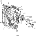
FIG. 1 is a schematic diagram of a sectional structure of a pneumatic nailing gun. -
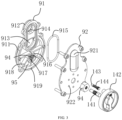
FIG. 2 is a schematic diagram of a partial stereoscopic exploded structure of the pneumatic nailing gun. -
FIG. 3 is a schematic diagram of an enlarged stereoscopic structure of an air cylinder end cover of the pneumatic nailing gun inFIG. 2 . -
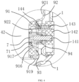
FIG. 4 is a schematic diagram of an enlarged stereoscopic structure of a part A inFIG. 1 . -
FIG. 5 is a schematic structural diagram of a state of a pneumatic structure when a first piston performs a compression stroke. -
FIG. 6 is a schematic structural diagram of a state of the pneumatic structure when the first piston completes the compression stroke. -
FIG. 7 is a schematic structural diagram of a state of the pneumatic structure after nailing. -
FIG. 8 is a schematic structural diagram of a state of the pneumatic structure when the first piston performs a return stroke. -
FIG. 9 is a schematic structural diagram of the pneumatic structure returning to an initial state when the first piston completes the return stroke. -
FIG. 10 is a schematic diagram of a partial stereoscopic exploded structure in Second Embodiment of the pneumatic nailing gun. -
FIG. 11 is a schematic diagram of a partial enlarged stereoscopic structure of an air cylinder end cover of the pneumatic nailing gun inFIG. 10 . -
FIG. 12 is a schematic diagram of an enlarged stereoscopic structure of a mounting seat and a ventilation column in Second Embodiment of the pneumatic nailing gun. -
FIG. 13 is a schematic diagram of an enlarged sectional structure of the air cylinder end cover in Second Embodiment. -
FIG. 14 is a schematic diagram of a sectional structure of an inner air hole and a ventilation hole in Second Embodiment of the nailing gun which are not conducted. -
FIG. 15 is a schematic diagram of a sectional structure of the inner air hole and the ventilation hole in Second Embodiment of the nailing gun which are partially conducted. -
FIG. 16 is a schematic diagram of a sectional structure of the inner air hole and the ventilation hole in Second Embodiment of the nailing gun which are wholly conducted. -
FIG. 17 is a schematic diagram of a stereoscopic structure of Third Embodiment of the nailing gun. -
FIG. 18 is a schematic diagram of an exploded structure of Third Embodiment. -
FIG. 19 is a schematic breakdown diagram of a partial structure in Third Embodiment. -
FIG. 20 is a schematic breakdown diagram of a partial structure in Third Embodiment. - In the drawing, 1 refers to shell; 2 refers to firing pin; 3 refers to locking member; 4 refers to first air cylinder; 41 refers to first piston; 411 refers to piston rod; 412 refers to crank; 42 refers to first air chamber; 5 refers to second air cylinder; 51 refers to second piston; 52 refers to second air chamber; 6 refers to motor; 61 refers to gear reducer; 7 refers to air hole; 71 refers to ventilation hole; 8 refers to ventilation channel; 9 refers to air cylinder end cover; 91 refers to inner end cover; 911 refers to first convex portion; 912 refers to second convex portion; 913 refers to first through hole; 914 refers to second through hole; 915 refers to sealing ring; 916 refers to fixed seat; 917 refers to ventilation groove; 918 refers to rib; 919 refers to pore; 92 refers to outer end cover; 921 refers to groove; 922 refers to positioning hole; 93 refers to air path; 94 refers to mounting seat; 941 refers to ventilation ring; 942 refers to threaded hole; 943 refers to flange; 944 refers to annular groove; 95 refers to concave cavity; 96 refers to mounting groove; 10 refers to battery, 11 refers to motor control panel; 12 refers to button; 13 refers to nail box; 14 refers to handle; 141 refers to threaded rod; 142 refers to turntable; 143 refers to steel ball; 144 refers to spring; 14a refers to connecting rod; 14b refers to boss turntable; 14b1 refers to touch table; 14c refers to spherical groove; 145 refers to ventilation column; 145a refers to air inlet hole; 145b refers to inner air hole; 145c refers to screw; 145d refers to boss; 15 refers to outer shell; 15a refers to fixed groove; 15a1 refers to U-shaped opening; 15b refers to rotating groove; 15b1 refers to opening; 16 refers to cover plate; 17 refers to movable rod; 17a refers to spring groove; 17b refers to spherical boss; and 18 refers to second spring.
- The present invention is further described hereinafter with reference to the accompanying drawings by the embodiments.
- As shown in
FIG. 1 , a pneumatic nailing gun comprises ashell 1 and afiring pin 2 arranged on theshell 1 and capable of reciprocating to nail, a lockingmember 3 capable of locking or unlocking thefiring pin 2 is arranged on theshell 1, the lockingmember 3 is provided with a locking hook, and a side portion of thefiring pin 2 is provided with a clamping groove. When in a locked state, the locking hook is clamped in the clamping groove to keep thefiring pin 2 locked and unable to move. Afirst air cylinder 4 and asecond air cylinder 5 are further arranged in theshell 1, afirst piston 41 capable of performing a compression stroke and a return stroke is arranged in thefirst air cylinder 4, and afirst air chamber 42 capable of storing air in thefirst air cylinder 4 is divided for thefirst piston 41. Apiston rod 411 is connected to thefirst piston 41, and a crank 412 is connected to thepiston rod 411. Amotor 6 arranged in theshell 1 is connected to agear reducer 61, an output shaft of thegear reducer 61 is connected to the crank 412, and thepiston rod 411 and the crank 412 form a crank connecting rod structure, which changes rotating power of themotor 6 into power for driving thefirst piston 41 to reciprocate linearly. Asecond piston 51 capable of reciprocating between a first position and a second position is arranged in thesecond air cylinder 5, the first position refers to a position where thesecond piston 51 is located when thefiring pin 2 is locked, the second position refers to a position where thesecond piston 51 is located after the firing pin performs nailing, and thefiring pin 2 is fixedly connected to thesecond piston 51. Asecond air chamber 52 in thesecond air cylinder 5 is divided for thesecond piston 51, and thefirst air chamber 42 and thesecond air chamber 52 are communicated with each other through a fully-closedventilation channel 8, so that thefirst air chamber 42, theventilation channel 8 and thesecond air chamber 52 form a pneumatic structure closed relative to the outside, A lower end of a holding portion of theshell 1 is further provided with adetachable battery 10, and thebattery 10 supplies power to amotor control panel 11. The lower end of the holding portion of theshell 1 is further provided with abutton 12, and thebutton 12 is also connected to themotor control panel 11. After thebutton 12 is pressed, themotor control panel 11 controls themotor 6 to drive thefirst piston 41 to perform the compression stroke and the return stroke. A front end of theshell 1 is provided with anail box 13, and a nail in thenail box 13 may automatically rise to a position in front of thefiring pin 2 under an action of a spring. After thefirst piston 41 completes the compression stroke, the locking hook is removed from the locking groove of thefiring pin 2 by an unlocking mechanism, so that thefiring pin 2 and thesecond piston 51 are both in an unlocked state. Thesecond piston 51 moves at a high speed under an action of a high pressure to drive thefiring pin 2 to hit the nail in front of thefiring pin 2, thus completing a nailing action once. Then, thefirst piston 41 performs the return stroke, and under an action of a negative pressure, thesecond piston 51 returns from the first position to the second position, and thefiring pin 2 is locked again by the locking hook. In the case of circulation, continuous nailing is realized. - With reference to
FIG. 1 , as shown inFIG. 2, FIG. 2 is a stereoscopic exploded view of the pneumatic nailing gun. The airsecond cylinder 5 is located above thefirst air cylinder 4, and thefirst air cylinder 4 and thesecond air cylinder 5 are coaxially arranged in parallel. A cylinder body end portion of thefirst air cylinder 4 and a cylinder body end portion of thesecond air cylinder 5 are provided with an aircylinder end cover 9 capable of sealing with a cylinder body of thefirst air cylinder 4 and a cylinder body of thesecond air cylinder 5, thefirst air cylinder 4 and thesecond air cylinder 5 share the same aircylinder end cover 9, which is mounted on one sides of thefirst air cylinder 4 and thesecond air cylinder 5, thus forming thefirst air chamber 42 and thesecond air chamber 52 located on the same side, and theventilation channel 8 is located in the aircylinder end cover 9. The aircylinder end cover 9 comprises aninner end cover 91 and anouter end cover 92, an inner side surface of theinner end cover 91 is provided with a firstconvex portion 911 inserted and hermetically connected in the cylinder body of thefirst air cylinder 4 and a secondconvex portion 912 inserted and hermetically connected in the cylinder body of thesecond sir cylinder 5 respectively, a first throughhole 913 penetrating through theinner end cover 91 is arranged in the firstconvex portion 911, a second throughhole 914 penetrating through theinner end cover 91 is arranged in the secondconvex portion 912, a sealingring 915 is arranged between theouter end cover 92 and theinner end cover 91, the sealingring 915 encloses the first throughhole 913 and the second throughhole 914 in thesealing ring 915, and agroove 921 communicating the first throughhole 913 with the second throughhole 914 is arranged on an inner side surface of theouter end cover 92. By this structure, theouter end cover 92 is attached to an outer side surface of the inner end cover and fixed to the cylinder body of thefirst air cylinder 4 and the cylinder body of thesecond air cylinder 5 by bolts, and after theinner end cover 91 and theouter end cover 92 are fixedly attached, theabove ventilation channel 8 is formed between theinner end cover 91 and theouter end cover 92. - As shown in
FIG. 3 andFIG. 4 , asingle air hole 7 communicated with theventilation channel 8 is arranged in the aircylinder end cover 9, and an aperture of theair hole 7 is 0.5 mm to 5 mm. Ahandle 14 capable of adjusting a ventilation capacity between theair hole 7 and the outside is arranged on theshell 1, thehandle 14 comprises a threadedrod 141, the threadedrod 141 is connected with the aircylinder end cover 9 through a thread, an inner end of the threadedrod 141 is a blocking end, and the blocking end is capable of being located in different positions in theair hole 7 after adjusting the handle, thus changing an air output of theair hole 7. As an alternative structure, theair hole 7 may be arranged in the cylinder body of thefirst air cylinder 4 or the cylinder body of thesecond air cylinder 5, and theair hole 7 is communicated with thefirst air chamber 42 or thesecond air chamber 52. Alternatively, a plurality ofair holes 7 may also be provided, and a total ventilation capacity of the plurality of air holes is the same as or similar to that of the single air hole with the aperture of 0.5 mm to 5 mm. In order to improve a strength, acylindrical mounting seat 94 made of metal copper and other materials is arranged on theinner end cover 91 and the outer end cover 92 of the aircylinder end cover 9, and the mountingseat 94 is embedded in the aircylinder end cover 9 made of plastic. A threaded hole is arranged in one end of the mountingseat 94, theair hole 7 is arranged in the other end of the mounting seat and anair inlet hole 145a is arranged in the other end of the mounting seat, the threadedrod 141 of thehandle 14 is connected in the threaded hole through a thread, an inner end of the threadedrod 141 extends to the hole opening of theair hole 7 and is located between theair hole 7 and theair inlet hole 145a. Thehandle 14 comprises aturntable 142 connected to an outer end of the threadedrod 141, asteel ball 143 for positioning and aspring 144 acting on thesteel ball 143 are further arranged at an edge of theturntable 142, a plurality ofpositioning holes 922 uniformly distributed in a circumferential direction are arranged on an outer side surface of the aircylinder end cover 9, and thesteel ball 143 abuts in a hole opening of one ofpositioning holes 922 under an action of thespring 144. When rotating the turntable, theturntable 142 rotates with an axial direction of the threadedrod 141 as a center of circle, and because thesteel ball 143 abuts in one hole opening under an action of thespring 144, during rotation, thesteel ball 143 may be separated from the original hole opening to enter the next hole opening along a track and make an impact sound to prompt a user to rotate the turntable to the next adjustment position to be positioned. - The
air hole 7 keeps the pneumatic structure in communication with the outside through anair path 93 arranged in the aircylinder end cover 9, and theair path 93 is arranged in a lower half portion of the aircylinder end cover 9 and located below theventilation channel 8. Specifically, theair path 93 comprises a cylindricalfixed seat 916 arranged on an outer side surface of theinner end cover 91, the mountingseat 94 is inserted in the fixedseat 916 and sealed with the fixedseat 916, aventilation groove 917 communicated with theair inlet hole 145a is arranged on the fixedseat 916, a plurality ofribs 918 are arranged outside the fixedseat 916 on the outer side surface of theinner end cover 91, aconcave cavity 95 is formed between theribs 918, apore 919 communicated with the outside is arranged at an outer edge of theinner end cover 91, and theventilation groove 917, theconcave cavity 95 and thepore 919 are communicated with each other. - A working process of the present invention is shown in
FIG. 5 to FIG. 9 . Thefirst air chamber 42, theventilation channel 8 and thesecond air chamber 52 form the pneumatic structure, positions of thefirst piston 41 and thesecond piston 51 shown inFIG. 1 are in an initial state, and theair hole 7 in the pneumatic structure keeps the determined ventilation capacity with the outside when thehandle 14 is adjusted in advance. When thesecond piston 51 is located in the first position, which means that thefirst piston 51 retracts at a bottom portion of thesecond air cylinder 5, the lockingmember 3 with the locking hook locks thefiring pin 2. - As shown in
FIG. 5 , thefirst piston 41 performs the compression stroke, so that air in thefirst air cylinder 4 is compressed to produce high pressure air, thus forming a high pressure state in the whole pneumatic structure. Because theair hole 7 is kept in communication with the outside through theair path 93, a part of the high pressure air is discharged to the outside through theventilation groove 917, theconcave cavity 95 and thepore 919, so that a pressure value of actual high pressure air is smaller than a pressure value produced by a predetermined stroke of thefirst piston 41, so as to adjust the nailing force. - As shown in
FIG. 6 andFIG. 7 , after thefirst piston 41 completes the compression stroke, the locking hook is removed from the locking groove of thefiring pin 2 by an unlocking mechanism, and the lockingmember 3 is in a release state, so that thefiring pin 2 and thesecond piston 51 are both in an unlocked state. Thesecond piston 51 moves at a high speed under an action of a high pressure to drive thefiring pin 2 to hit the nail in front of thefiring pin 2, thus completing a nailing action once. At the moment, thesecond piston 51 is located in the second position. - As shown in
FIG. 8 , thefirst piston 41 performs the return stroke. Because the pneumatic structure formed by thefirst air chamber 42, theventilation channel 8 and thesecond air chamber 52 is closed except theair hole 7, and during the return stroke, thefirst air chamber 42 produces a negative pressure relative to thesecond air chamber 52, and thesecond piston 51 in thesecond air cylinder 5 moves to the first position. In the return process, theair hole 7 is kept in communication with the outside, and a pressure of thefirst air chamber 42 is also lower than an atmospheric pressure, so that thefirst air chamber 42 is filled with a part of air in advance through theventilation groove 917, theconcave cavity 95 and thepore 919, and air needed by thefirst air chamber 42 is replenished in advance. Because only a certain amount of external air enters thefirst air chamber 42 after the air hole is matched with the handle, it is insufficient to affect the negative pressure produced by thefirst air chamber 42 relative to thesecond air chamber 52, and a gradually increased torque of themotor 6 can be smoothed when thefirst piston 41 returns, so that themotor 6 runs steadily and themotor 6 keeps running precisely. - As shown in
FIG. 9 , when thefirst piston 41 returns to the initial position, thesecond piston 51 also returns to the first position under an action of the negative pressure, and the firing pin is locked again by the lockingmember 3 to complete one nailing circulation. - As shown in
FIG. 10 to FIG. 13 , Second Embodiment is basically the same as First Embodiment in structure, with a difference in that, in Second embodiment, the mountingseat 94 and the fixedseat 916 in the nailing gun are of another structure. The mountingseat 94 comprises aflange 943, theflange 943 has a hexagonal structure, and theflange 943 is mounted in the mounting groove 96 of theinner end cover 91. The mountingseat 94 comprises theair hole 7, theair hole 7 is communicated with aventilation ring 941, theventilation hole 71 is formed in theventilation ring 941, theventilation hole 71 is communicated with theair inlet hole 145a, and anannular groove 944 is formed on an outer wall of the mountingseat 94. In this embodiment, theventilation groove 917 of another structure is further arranged on theinner end cover 91, and theannular groove 944 is communicated with theventilation groove 917. - A
ventilation column 145 is located in the mountingseat 94, theventilation column 145 comprises a ventilation rod, theair inlet hole 145a and aninner air hole 145b communicated with theair inlet hole 145a are arranged in the ventilation rod, and theair inlet hole 145a is communicated with thefirst air chamber 42. Ascrew 145c is arranged on theventilation column 145, the mountingseat 94 is further provided with a threadedhole 942, thescrew 145c is mounted in the threadedhole 942 through a thread, and theventilation column 145 is connected with thehandle 14 through aboss 145d. When thehandle 14 rotates, thescrew 145c and the threadedhole 942 rotate relatively, and theventilation column 145 moves in theair hole 7. - A working principle of this embodiment is as shown in
FIG. 13 to FIG. 16 , and is specifically as follows. The nailing force adjustment of the nailing gun is realized by adjusting thehandle 14 to change a ventilation capacity between the pneumatic structure and external atmosphere, and the ventilation capacity adjustment is mainly determined by changing an overlapping degree of theinner air hole 145b and theventilation ring 941. As shown inFIG. 14 , when the nailing gun is in an initial state, air in thefirst air chamber 42 diffuses into theair inlet hole 145a of theventilation column 145, and because theinner air hole 145b is located in theair hole 7 at the moment, theinner air hole 145b and theventilation ring 941 are completely staggered, so that the pneumatic structure is isolated from the external atmosphere, and after the piston in thefirst cylinder 4 completes the compression stroke, a pressure value of actual high pressure air in thefirst air chamber 42 is equal to a pressure value produced by a predetermined stroke of thefirst piston 41 at the moment. As shown inFIG. 15 , when thehandle 14 is adjusted, theventilation column 145 rotates in the mountingseat 94, and when theinner air hole 145b in the ventilation rod and theventilation ring 941 are partially overlapped, air in the pneumatic structure is communicated with the external atmosphere through theair inlet hole 145a, theinner air hole 145b, theventilation ring 941 and theventilation hole 71, and the pressure value of the actual high pressure air in thefirst air chamber 42 is smaller than the pressure value produced by the predetermined stroke of thefirst piston 41 at the moment. As shown inFIG. 16 , when theinner air hole 145b and theventilation ring 941 are completely overlapped by adjusting thehandle 14, the pressure value of the actual high pressure air in thefirst air chamber 42 is smaller than the pressure value produced by the predetermined stroke of thefirst piston 41 at the moment. In this embodiment, thehandle 14 needs to rotate for a certain number of turns to partially align theinner air hole 145b with theventilation ring 941, and then a ventilation capacity between the pneumatic structure and the outside starts to be changed, thus avoiding the situation that when an operator touches thehandle 14 unintentionally, thehandle 14 rotates to change the position of the blocking portion, so that the pneumatic structure is communicated with the outside. Meanwhile, the ventilation rod is located in the throughhole 7 of the mountingseat 94, so that a sealing performance in the mountingseat 94 is ensured, and the adjustment precision of the nailing force of the nailing gun is improved. - As shown in
FIG. 17 to FIG. 20 , Second Embodiment is basically the same as First Embodiment in structure, with a difference in that, theboss 145d has a structure as shown inFIG. 19 , thehandle 14 comprises a connectingrod 14a connected with theboss 145d and aboss turntable 14b connected to an outer end of the connectingrod 14a, a fixedgroove 15a is arranged on anouter shell 15 of the nailing gun, acover plate 16 is mounted on a groove opening of the fixedgroove 15a, amovable rod 17 is arranged in the fixedgroove 15a, one end of themovable rod 17 is provided with aspring groove 17a, thespring groove 17a is provided with asecond spring 18, thesecond spring 18 abuts against the aircylinder end cover 9, and the other end of themovable rod 17 is aspherical boss 17b. Aspherical groove 14c matched with thespherical boss 17b in shape is formed on theboss turntable 14b, and thespherical boss 17b passes through a U-shaped opening 15a1 of the fixedgroove 15a and abuts against thespherical groove 14c. Arotating groove 15b is further arranged on theouter shell 15, theboss turntable 14b rotates in therotating groove 15b, numbers corresponding to thespherical groove 14c are further arranged on an end surface of theboss turntable 14b, the corresponding herein means that each number represents onespherical groove 14c, and the numbers are arranged on a touch table 14b1 of theboss turntable 14c at intervals. Therotating groove 15b is provided with an opening 15b1, and when adjusting theboss turntable 14b, a user places the boss turntable on the touch table 14b1 through the opening 15b1 to make theboss turntable 14c rotate, and a rotation mark is further arranged on theboss turntable 14c for prompting a direction of rotation. - The specific embodiments described herein are only illustrative to the spirit of the present invention. Those skilled in the technical field to which the present invention belongs may make various modifications or supplements to the specific embodiments described or make substitutions in a similar way, without departing from the spirit of the present invention or exceeding the scope defined by the appended claims.
- Although many terms such as the shell, the firing pin, the crank and the first air cylinder are used herein, the possibility of using other terms is not excluded. These terms are only used to describe and explain the essence of the present invention more conveniently; and the explanation of the terms as any additional restrictions is against the spirit of the present invention.
Claims (15)
- A pneumatic nailing gun with an adjustable nailing force, comprising a shell (1) and a firing pin (2) arranged on the shell (1) and capable of reciprocating to nail, a first air cylinder (4) and a second air cylinder (5) being further arranged in the shell (1), a first piston (41) capable of performing a compression stroke and a return stroke being arranged in the first air cylinder (4), a first air chamber (42) capable of storing air in the first air cylinder (4) being divided for the first piston (41), the first piston (41) being driven by a motor (6) to reciprocate linearly, a second piston (51) capable of reciprocating between a first position and a second position being arranged in the second air cylinder (5), the above firing pin (2) being fixedly connected to the second piston (51), a second air chamber (52) in the second air cylinder (5) being divided for the second piston (51), and the first air chamber (42) and the second air chamber (52) being communicated with each other through a ventilation channel (8), so that the first air chamber (42), the ventilation channel (8) and the second air chamber (52) form a pneumatic structure closed relative to the outside, characterized in that, an air hole (7) capable of keeping the pneumatic structure in communication with the outside is arranged in the pneumatic structure, a handle (14) capable of adjusting a ventilation capacity between the air hole (7) and the outside is arranged on the shell (1), when the second piston (51) is located in the first position and the firing pin (2) is locked, the first piston (41) performs the compression stroke to compress air in the first air chamber (42), and a part of the compressed air is discharged to the outside through the air hole (7), and when the second piston (51) is located in the second position and the firing pin (2) is unlocked, the first piston (41) performs the return stroke to make the second piston (51) return to the first position to be locked, and a part of external air is sucked into the pneumatic structure through the air hole (7).
- The pneumatic nailing gun with the adjustable nailing force according to claim 1, wherein the second air cylinder (5) is coaxially located outside the first air cylinder (4) in parallel, a cylinder body end portion of the first air cylinder (4) and a cylinder body end portion of the second air cylinder (5) are provided with an air cylinder end cover (9) capable of sealing with a cylinder body of the first air cylinder (4) and a cylinder body of the second air cylinder (5), the above ventilation channel (8) is located in the air cylinder end cover (9), the above air hole (7) is arranged in the air cylinder end cover (9) or the cylinder body of the first air cylinder (4) or the cylinder body of the second air cylinder (5), and the air hole (7) is communicated with the ventilation channel (8) or communicated with the first air chamber (42) or the second air chamber (52).
- The pneumatic nailing gun with the adjustable nailing force according to claim 2, wherein a single air hole (7) is provided, with an aperture of 0.5 mm to 5 mm, or a plurality of air holes (7) are provided.
- The pneumatic nailing gun with the adjustable nailing force according to claim 2, wherein the handle (14) comprises a threaded rod (141), the threaded rod (141) is connected with the air cylinder end cover (9) through a thread, an inner end of the threaded rod (141) is a blocking end, and the blocking end is capable of being located in different positions and blocking the air hole (7) after adjusting the handle (14), thus changing an air output of the air hole (7).
- The pneumatic nailing gun with the adjustable nailing force according to claim 3, wherein the handle (14) comprises a swinging rod hinged on the shell (1), an end portion of the swinging rod is provided with a shielding plate, and the shielding plate is capable of shielding a part of air hole (7) after adjusting the handle (14), thus changing an air output of the air hole (7).
- The pneumatic nailing gun with the adjustable nailing force according to claim 4, wherein the handle (14) comprises a turntable (142) fixedly connected to an outer end of the threaded rod (141), a steel ball (143) for positioning and a spring (144) acting on the steel ball (143) are further arranged on the turntable (142), a plurality of positioning holes (922) uniformly distributed in a circumferential direction are arranged on an outer side surface of the air cylinder end cover (9), and the steel ball (143) abuts in a hole opening of one of positioning holes (922) under an action of the spring (144).
- The pneumatic nailing gun with the adjustable nailing force according to claim 6, wherein a cylindrical mounting seat (94) is arranged on the air cylinder end cover (9), a threaded hole is arranged in one end of the mounting seat (94), the above air hole (7) is arranged in the other end of the mounting seat and a ventilation hole (71) is arranged in the other end of the mounting seat, the threaded rod (141) of the handle (14) is connected in the threaded hole through a thread, an inner end of the threaded rod (141) extends to the hole opening of the air hole (7) and is located between the air hole (7) and the ventilation hole (71), a lower half portion of the air cylinder end cover (9) is further provided with an air path (93) communicated with the air hole (71), and the air path (93) is communicated with the outside.
- The pneumatic nailing gun with the adjustable nailing force according to claim 6, wherein the mounting seat (94) is fixedly connected to the air cylinder end cover (9), the air hole (7) is arranged in the mounting seat (94), a ventilation hole (71) communicated with the air hole is further arranged in the mounting seat (94), the ventilation hole (71) is capable of keeping in communication with the outside, the air hole (7) is movably connected with a ventilation column (145), the ventilation column (145) comprises a ventilation rod, the ventilation rod comprises an air inlet hole (145a) and an inner air hole (145b) communicated with the air inlet hole (145a), the air inlet hole (145a) is communicated with the first air chamber (42), the ventilation column (145) is connected with the handle (14), and under the adjustment of the handle (14), the inner air hole (145b) moves in the air hole (7), and an inner peripheral surface of the air hole (7) and the ventilation hole (71) form a conducting or closing state through the inner air hole (145b).
- The pneumatic nailing gun with the adjustable nailing force according to claim 8, wherein the air cylinder end cover (9) comprises an inner end cover (91) and an outer end cover (92), the outer end cover (92) is attached to an outer side surface of the inner end cover (91) to form the above ventilation channel (8) between the inner end cover (91) and the outer end cover (92), and the air path (93) is arranged below the ventilation channel (8).
- The pneumatic nailing gun with the adjustable nailing force according to claim 9, wherein the air path (93) comprises a cylindrical fixed seat (916) arranged on an outer side surface of the inner end cover (91), the above mounting seat (94) is inserted in the fixed seat (916) and sealed with the fixed seat (916), a ventilation groove (917) communicated with the above ventilation hole (71) is arranged on the fixed seat (916), a plurality of ribs (918) are arranged outside the fixed seat (916) on the outer side surface of the inner end cover (91), a concave cavity (95) is formed between the ribs (918), a pore (919) communicated with the outside is arranged at an outer edge of the inner end cover (91), and the ventilation groove (917), the concave cavity (95) and the pore (919) are communicated with each other.
- The pneumatic nailing gun with the adjustable nailing force according to claim 10, wherein an inner side surface of the inner end cover (91) is provided with a first convex portion (911) inserted and hermetically connected in the cylinder body of the first air cylinder (4) and a second convex portion (912) inserted and hermetically connected in the cylinder body of the second sir cylinder (5) respectively, a first through hole (913) penetrating through the inner end cover (91) is arranged in the first convex portion (911), a second through hole (914) penetrating through the inner end cover (91) is arranged in the second convex portion (912), a sealing ring (915) is arranged between the outer end cover (92) and the inner end cover (91), the sealing ring (915) encloses the first through hole (913) and the second through hole (914) in the sealing ring (915), and a groove (921) communicating the first through hole (913) with the second through hole (914) is arranged on the outer end cover (92).
- The pneumatic nailing gun with the adjustable nailing force according to claim 8, wherein the mounting seat (94) comprises a ventilation ring (941) communicated with the air hole (7), the ventilation hole (71) is formed in the ventilation ring (941), the ventilation column (145) comprises a screw (145c), the mounting seat (94) further comprises a threaded hole (942), the screw (145c) is mounted in the threaded hole (942) through a thread, the ventilation column (145) is connected with the handle through a boss (145d), the ventilation column (145) moves in the air hole (7) through relative rotation of the screw (145c) and the threaded hole (942), and the air hole (7) forms a conducting or closing state with the ventilation ring (941) through the inner air hole (145b).
- The pneumatic nailing gun with the adjustable nailing force according to claim 12, wherein an end portion of the mounting seat (94) is provided with a flange (943), the fixed seat (916) comprises a mounting groove (96) matched with the flange (943) in shape, the flange (943) is located in the mounting groove (96), an annular groove (944) is further formed on an outer wall of the mounting seat (94), and the annular groove (944) is communicated with the above ventilation groove (917).
- The pneumatic nailing gun with the adjustable nailing force according to claim 13, wherein the nailing gun further comprises an outer shell (15), a fixed groove (15a) is arranged on the outer shell (15), a cover plate (16) is mounted on a groove opening of the fixed groove (15a), a movable rod (17) is arranged in the fixed groove (15a), one end of the movable rod (17) is provided with a spring groove (17a) for mounting a second spring (18), the second spring (18) abuts against the air cylinder end cover (9), the other end of the movable rod (17) is a spherical boss (17b), the handle (14) comprises a connecting rod (14a) and a boss turntable (14b) connected to an outer end of the connecting rod (14a), the connecting rod (14a) is connected with the boss (145d), a spherical groove (14c) matched with the spherical boss (17b) in shape is formed on the boss turntable (14b), and the spherical boss (17b) passes through a U-shaped opening (15a1) of the fixed groove (15a) and abuts against the spherical groove (14c).
- The pneumatic nailing gun with the adjustable nailing force according to claim 14, wherein a rotating groove (15b) with an opening (15b1) is further arranged on the outer shell (15), the boss turntable (14b) rotates in the rotating groove (15b), numbers corresponding to the spherical groove (14c) are further arranged on an end surface of the boss turntable (14b), and the numbers are arranged on a touch table (14b1) of the boss turntable (14b) at intervals.
Applications Claiming Priority (3)
| Application Number | Priority Date | Filing Date | Title |
|---|---|---|---|
| CN202110143489.8A CN112828827B (en) | 2021-02-02 | 2021-02-02 | Pneumatic nailing gun with adjustable nailing force |
| CN202122238613.7U CN215942802U (en) | 2021-09-15 | 2021-09-15 | Nailing gun with adjustable nail ejecting force |
| PCT/CN2022/072211 WO2022166564A1 (en) | 2021-02-02 | 2022-01-17 | Pneumatic nailing gun with adjustable nailing force |
Publications (4)
| Publication Number | Publication Date |
|---|---|
| EP4289561A1 true EP4289561A1 (en) | 2023-12-13 |
| EP4289561A4 EP4289561A4 (en) | 2025-01-01 |
| EP4289561B1 EP4289561B1 (en) | 2026-02-18 |
| EP4289561C0 EP4289561C0 (en) | 2026-02-18 |
Family
ID=82741903
Family Applications (1)
| Application Number | Title | Priority Date | Filing Date |
|---|---|---|---|
| EP22748843.4A Active EP4289561B1 (en) | 2021-02-02 | 2022-01-17 | Pneumatic nailing gun with adjustable nailing force |
Country Status (7)
| Country | Link |
|---|---|
| US (1) | US12350797B2 (en) |
| EP (1) | EP4289561B1 (en) |
| JP (1) | JP7790751B2 (en) |
| KR (1) | KR102809522B1 (en) |
| AU (1) | AU2022215680B2 (en) |
| CA (1) | CA3207317A1 (en) |
| WO (1) | WO2022166564A1 (en) |
Families Citing this family (1)
| Publication number | Priority date | Publication date | Assignee | Title |
|---|---|---|---|---|
| CN115383684B (en) * | 2022-09-06 | 2024-11-19 | 浙江荣鹏气动工具股份有限公司 | Double-cylinder electric nailing gun with simplified locking mechanism |
Family Cites Families (12)
| Publication number | Priority date | Publication date | Assignee | Title |
|---|---|---|---|---|
| JP3654099B2 (en) * | 1999-12-03 | 2005-06-02 | 日立工機株式会社 | Driving machine |
| JP2012187640A (en) * | 2009-07-24 | 2012-10-04 | Makita Corp | Hammering tool |
| US8079504B1 (en) * | 2010-11-04 | 2011-12-20 | Tricord Solutions, Inc. | Fastener driving apparatus |
| US8800834B2 (en) * | 2011-05-11 | 2014-08-12 | Tricord Solutions, Inc. | Fastener driving apparatus |
| CN102814795A (en) * | 2011-06-08 | 2012-12-12 | 大里兴业有限公司 | Rotational speed control device of pneumatic tool and rotational speed control method of rotational speed control device |
| JP5859372B2 (en) * | 2012-04-27 | 2016-02-10 | 株式会社マキタ | Driving tool |
| DE102012210347A1 (en) * | 2012-06-19 | 2013-12-19 | Hilti Aktiengesellschaft | Setting tool and control method |
| CN206795737U (en) * | 2017-03-28 | 2017-12-26 | 南京德朔实业有限公司 | Nail gun |
| CN109693210B (en) * | 2017-10-20 | 2021-05-11 | 南京德朔实业有限公司 | Nailing gun |
| CN108527255B (en) * | 2018-03-10 | 2021-03-26 | 南京腾亚精工科技股份有限公司 | Nailing power adjustable mosquito nail gun |
| CN112828827B (en) * | 2021-02-02 | 2025-05-23 | 台州市钉霸电动工具有限公司 | Pneumatic nailing gun with adjustable nailing force |
| CN116175489A (en) * | 2021-11-29 | 2023-05-30 | 台州市大江实业有限公司 | Force supply unit for nail gun, nail driving mechanism and nail gun |
-
2022
- 2022-01-17 WO PCT/CN2022/072211 patent/WO2022166564A1/en not_active Ceased
- 2022-01-17 CA CA3207317A patent/CA3207317A1/en active Pending
- 2022-01-17 AU AU2022215680A patent/AU2022215680B2/en active Active
- 2022-01-17 EP EP22748843.4A patent/EP4289561B1/en active Active
- 2022-01-17 KR KR1020237027553A patent/KR102809522B1/en active Active
- 2022-01-17 JP JP2023570329A patent/JP7790751B2/en active Active
-
2023
- 2023-08-01 US US18/363,721 patent/US12350797B2/en active Active
Also Published As
| Publication number | Publication date |
|---|---|
| JP7790751B2 (en) | 2025-12-23 |
| US20230373070A1 (en) | 2023-11-23 |
| EP4289561B1 (en) | 2026-02-18 |
| KR102809522B1 (en) | 2025-05-16 |
| EP4289561C0 (en) | 2026-02-18 |
| AU2022215680B2 (en) | 2024-09-05 |
| AU2022215680A9 (en) | 2024-07-18 |
| WO2022166564A1 (en) | 2022-08-11 |
| EP4289561A4 (en) | 2025-01-01 |
| KR20230129540A (en) | 2023-09-08 |
| CA3207317A1 (en) | 2022-08-11 |
| JP2024504874A (en) | 2024-02-01 |
| US12350797B2 (en) | 2025-07-08 |
| AU2022215680A1 (en) | 2023-08-17 |
Similar Documents
| Publication | Publication Date | Title |
|---|---|---|
| CN112828827B (en) | Pneumatic nailing gun with adjustable nailing force | |
| US11559876B2 (en) | Electric nail gun | |
| US20190126452A1 (en) | Pneumatic Nail Gun | |
| US7896101B2 (en) | Pneumatically operated power tool having mechanism for changing compressed air pressure | |
| US20210205969A1 (en) | Fastener driving tool | |
| US11034006B2 (en) | Pneumatic linear fastener driving tool | |
| JP3618286B2 (en) | Smooth exhaust valve | |
| US12350797B2 (en) | Pneumatic nailing gun with adjustable nailing force | |
| US20080308287A1 (en) | Impact tool | |
| CN102059680A (en) | Nailing gun | |
| TW201313406A (en) | Driver | |
| CN215942802U (en) | Nailing gun with adjustable nail ejecting force | |
| CN215148783U (en) | Pneumatic nailing gun with adjustable nailing force | |
| CN114654429A (en) | Firing pin locking structure of nailing gun | |
| US20110174858A1 (en) | Adjusting Mechanism for Nailing Power of Nailing Gun | |
| KR101983698B1 (en) | Swash plate type compressor | |
| JP6169727B2 (en) | Air compressor equipment | |
| JP2016043445A (en) | Driver | |
| CN201693520U (en) | Nail gun | |
| CN210135063U (en) | Piston type compressor | |
| KR102067137B1 (en) | Swash plate type compressor | |
| JP4434848B2 (en) | Fixing device driving device with switchable driving force | |
| JP2001105337A (en) | Screwdriver | |
| JP5110301B2 (en) | Pneumatic tool | |
| JPH0753901Y2 (en) | Operating mode switching mechanism for driving machine |
Legal Events
| Date | Code | Title | Description |
|---|---|---|---|
| STAA | Information on the status of an ep patent application or granted ep patent |
Free format text: STATUS: THE INTERNATIONAL PUBLICATION HAS BEEN MADE |
|
| PUAI | Public reference made under article 153(3) epc to a published international application that has entered the european phase |
Free format text: ORIGINAL CODE: 0009012 |
|
| STAA | Information on the status of an ep patent application or granted ep patent |
Free format text: STATUS: REQUEST FOR EXAMINATION WAS MADE |
|
| 17P | Request for examination filed |
Effective date: 20230802 |
|
| AK | Designated contracting states |
Kind code of ref document: A1 Designated state(s): AL AT BE BG CH CY CZ DE DK EE ES FI FR GB GR HR HU IE IS IT LI LT LU LV MC MK MT NL NO PL PT RO RS SE SI SK SM TR |
|
| DAV | Request for validation of the european patent (deleted) | ||
| DAX | Request for extension of the european patent (deleted) | ||
| A4 | Supplementary search report drawn up and despatched |
Effective date: 20241202 |
|
| RIC1 | Information provided on ipc code assigned before grant |
Ipc: B25C 1/04 20060101AFI20241126BHEP |
|
| GRAP | Despatch of communication of intention to grant a patent |
Free format text: ORIGINAL CODE: EPIDOSNIGR1 |
|
| STAA | Information on the status of an ep patent application or granted ep patent |
Free format text: STATUS: GRANT OF PATENT IS INTENDED |
|
| INTG | Intention to grant announced |
Effective date: 20251022 |
|
| GRAS | Grant fee paid |
Free format text: ORIGINAL CODE: EPIDOSNIGR3 |
|
| GRAA | (expected) grant |
Free format text: ORIGINAL CODE: 0009210 |
|
| STAA | Information on the status of an ep patent application or granted ep patent |
Free format text: STATUS: THE PATENT HAS BEEN GRANTED |
|
| AK | Designated contracting states |
Kind code of ref document: B1 Designated state(s): AL AT BE BG CH CY CZ DE DK EE ES FI FR GB GR HR HU IE IS IT LI LT LU LV MC MK MT NL NO PL PT RO RS SE SI SK SM TR |
|
| REG | Reference to a national code |
Ref country code: CH Ref legal event code: F10 Free format text: ST27 STATUS EVENT CODE: U-0-0-F10-F00 (AS PROVIDED BY THE NATIONAL OFFICE) Effective date: 20260218 Ref country code: GB Ref legal event code: FG4D |
|
| REG | Reference to a national code |
Ref country code: DE Ref legal event code: R096 Ref document number: 602022030670 Country of ref document: DE |
|
| REG | Reference to a national code |
Ref country code: IE Ref legal event code: FG4D |
|
| U01 | Request for unitary effect filed |
Effective date: 20260313 |
|
| U07 | Unitary effect registered |
Designated state(s): AT BE BG DE DK EE FI FR IT LT LU LV MT NL PT RO SE SI Effective date: 20260319 |