EP4289333A1 - Endoscope device - Google Patents
Endoscope device Download PDFInfo
- Publication number
- EP4289333A1 EP4289333A1 EP23174044.0A EP23174044A EP4289333A1 EP 4289333 A1 EP4289333 A1 EP 4289333A1 EP 23174044 A EP23174044 A EP 23174044A EP 4289333 A1 EP4289333 A1 EP 4289333A1
- Authority
- EP
- European Patent Office
- Prior art keywords
- balloon
- controller
- endoscope
- remote controller
- image
- Prior art date
- Legal status (The legal status is an assumption and is not a legal conclusion. Google has not performed a legal analysis and makes no representation as to the accuracy of the status listed.)
- Granted
Links
Images






Classifications
-
- A—HUMAN NECESSITIES
- A61—MEDICAL OR VETERINARY SCIENCE; HYGIENE
- A61B—DIAGNOSIS; SURGERY; IDENTIFICATION
- A61B1/00—Instruments for performing medical examinations of the interior of cavities or tubes of the body by visual or photographical inspection, e.g. endoscopes; Illuminating arrangements therefor
- A61B1/00064—Constructional details of the endoscope body
- A61B1/00071—Insertion part of the endoscope body
- A61B1/0008—Insertion part of the endoscope body characterised by distal tip features
- A61B1/00082—Balloons
-
- A—HUMAN NECESSITIES
- A61—MEDICAL OR VETERINARY SCIENCE; HYGIENE
- A61B—DIAGNOSIS; SURGERY; IDENTIFICATION
- A61B1/00—Instruments for performing medical examinations of the interior of cavities or tubes of the body by visual or photographical inspection, e.g. endoscopes; Illuminating arrangements therefor
- A61B1/00002—Operational features of endoscopes
- A61B1/00004—Operational features of endoscopes characterised by electronic signal processing
- A61B1/00006—Operational features of endoscopes characterised by electronic signal processing of control signals
-
- A—HUMAN NECESSITIES
- A61—MEDICAL OR VETERINARY SCIENCE; HYGIENE
- A61B—DIAGNOSIS; SURGERY; IDENTIFICATION
- A61B1/00—Instruments for performing medical examinations of the interior of cavities or tubes of the body by visual or photographical inspection, e.g. endoscopes; Illuminating arrangements therefor
- A61B1/00002—Operational features of endoscopes
- A61B1/00039—Operational features of endoscopes provided with input arrangements for the user
- A61B1/0004—Operational features of endoscopes provided with input arrangements for the user for electronic operation
-
- A—HUMAN NECESSITIES
- A61—MEDICAL OR VETERINARY SCIENCE; HYGIENE
- A61B—DIAGNOSIS; SURGERY; IDENTIFICATION
- A61B1/00—Instruments for performing medical examinations of the interior of cavities or tubes of the body by visual or photographical inspection, e.g. endoscopes; Illuminating arrangements therefor
- A61B1/00002—Operational features of endoscopes
- A61B1/00039—Operational features of endoscopes provided with input arrangements for the user
- A61B1/00042—Operational features of endoscopes provided with input arrangements for the user for mechanical operation
-
- A—HUMAN NECESSITIES
- A61—MEDICAL OR VETERINARY SCIENCE; HYGIENE
- A61B—DIAGNOSIS; SURGERY; IDENTIFICATION
- A61B1/00—Instruments for performing medical examinations of the interior of cavities or tubes of the body by visual or photographical inspection, e.g. endoscopes; Illuminating arrangements therefor
- A61B1/00002—Operational features of endoscopes
- A61B1/00043—Operational features of endoscopes provided with output arrangements
- A61B1/00045—Display arrangement
-
- A—HUMAN NECESSITIES
- A61—MEDICAL OR VETERINARY SCIENCE; HYGIENE
- A61B—DIAGNOSIS; SURGERY; IDENTIFICATION
- A61B1/00—Instruments for performing medical examinations of the interior of cavities or tubes of the body by visual or photographical inspection, e.g. endoscopes; Illuminating arrangements therefor
- A61B1/00002—Operational features of endoscopes
- A61B1/00043—Operational features of endoscopes provided with output arrangements
- A61B1/00045—Display arrangement
- A61B1/0005—Display arrangement combining images e.g. side-by-side, superimposed or tiled
-
- A—HUMAN NECESSITIES
- A61—MEDICAL OR VETERINARY SCIENCE; HYGIENE
- A61B—DIAGNOSIS; SURGERY; IDENTIFICATION
- A61B1/00—Instruments for performing medical examinations of the interior of cavities or tubes of the body by visual or photographical inspection, e.g. endoscopes; Illuminating arrangements therefor
- A61B1/00002—Operational features of endoscopes
- A61B1/00043—Operational features of endoscopes provided with output arrangements
- A61B1/00055—Operational features of endoscopes provided with output arrangements for alerting the user
-
- A—HUMAN NECESSITIES
- A61—MEDICAL OR VETERINARY SCIENCE; HYGIENE
- A61B—DIAGNOSIS; SURGERY; IDENTIFICATION
- A61B1/00—Instruments for performing medical examinations of the interior of cavities or tubes of the body by visual or photographical inspection, e.g. endoscopes; Illuminating arrangements therefor
- A61B1/00131—Accessories for endoscopes
- A61B1/00135—Oversleeves mounted on the endoscope prior to insertion
-
- H—ELECTRICITY
- H04—ELECTRIC COMMUNICATION TECHNIQUE
- H04N—PICTORIAL COMMUNICATION, e.g. TELEVISION
- H04N23/00—Cameras or camera modules comprising electronic image sensors; Control thereof
- H04N23/50—Constructional details
- H04N23/555—Constructional details for picking-up images in sites, inaccessible due to their dimensions or hazardous conditions, e.g. endoscopes or borescopes
-
- H—ELECTRICITY
- H04—ELECTRIC COMMUNICATION TECHNIQUE
- H04N—PICTORIAL COMMUNICATION, e.g. TELEVISION
- H04N7/00—Television systems
- H04N7/18—Closed-circuit television [CCTV] systems, i.e. systems in which the video signal is not broadcast
- H04N7/183—Closed-circuit television [CCTV] systems, i.e. systems in which the video signal is not broadcast for receiving images from a single remote source
-
- A—HUMAN NECESSITIES
- A61—MEDICAL OR VETERINARY SCIENCE; HYGIENE
- A61M—DEVICES FOR INTRODUCING MEDIA INTO, OR ONTO, THE BODY; DEVICES FOR TRANSDUCING BODY MEDIA OR FOR TAKING MEDIA FROM THE BODY; DEVICES FOR PRODUCING OR ENDING SLEEP OR STUPOR
- A61M25/00—Catheters; Hollow probes
- A61M25/10—Balloon catheters
- A61M25/1018—Balloon inflating or inflation-control devices
- A61M25/10184—Means for controlling or monitoring inflation or deflation
- A61M25/10187—Indicators for the level of inflation or deflation
- A61M25/10188—Inflation or deflation data displays
Definitions
- the present invention relates to an endoscope device that controls inflation and deflation of a balloon of an endoscope.
- switching between inflation and deflation of each balloon can be performed individually by operating a remote controller connected to the balloon controller by an operator (including an assistant, the same applies hereinafter).
- a switch controller operation switch
- the balloon controller is provided in an operating part of the endoscope of the endoscope device disclosed in JP2005-261781A . By operating this switch by the operator, switching between inflation and deflation of each balloon can be performed individually.
- a balloon state image showing whether each balloon is in an inflated state or a deflated state is displayed on a monitor.
- the present invention has been made in view of such circumstances, and an object of the present invention is to provide an endoscope device that enables an operator to easily grasp which operation is being operated in a case in which the operator operates a controller operation switch provided in an endoscope.
- An endoscope device for achieving the object of the present invention comprises: a balloon; a balloon controller that controls inflation and deflation of the balloon; a remote controller that is connected to the balloon controller and operates the balloon controller, the remote controller being capable of inputting a plurality of types of balloon operations including an inflation operation and a deflation operation of the balloon; a controller operation switch for operating the balloon controller, the controller operation switch being provided in an endoscope and capable of inputting a plurality of types of the balloon operations that are common to the remote controller; and a processor, in which the processor is configured to: cause a monitor to display an endoscope image captured by the endoscope and a remote controller image which is an image of the remote controller; and in a case in which the balloon operation is input to the controller operation switch, reflect a type of the balloon operation input to the controller operation switch on the remote controller image displayed on the monitor.
- an operator can easily grasp what kind of balloon operation has been performed on the controller operation switch even in a state in which the operator gazes at the monitor.
- the remote controller includes a plurality of types of individual operation switches corresponding to the plurality of types of balloon operations
- the remote controller image includes images of the plurality of types of individual operation switches
- the processor is configured to, in a case in which the balloon operation is input to the controller operation switch, change a display mode of an image of the individual operation switch corresponding to the type of the balloon operation. Accordingly, it is possible to easily grasp which operation the operator is performing in a case in which the operator performs the balloon operation using the controller operation switch.
- the balloon is provided at at least one of a distal end portion of an insertion part of the endoscope or a distal end portion of an overtube through which the insertion part is inserted.
- the balloon is provided at the distal end portion of the insertion part and the distal end portion of the overtube, the balloon controller controls inflation and deflation of the balloon for each of the balloons, the remote controller is capable of inputting the balloon operation for each of the balloons, and the processor is configured to reflect the type of the balloon operation input to the controller operation switch on the remote controller image, for each of the balloons. Accordingly, even with a double-balloon type endoscope device, in a case in which the operator performs the balloon operation using the controller operation switch, it is possible to easily grasp which operation the operator is performing.
- the endoscope device further comprises: an emergency stop switch for bringing the balloon controller to an emergency stop, in which the processor is configured to, in a case in which the emergency stop switch is operated, cause the monitor to display information indicating that the balloon controller has been brought to an emergency stop. Accordingly, it is possible to notify the operator that the balloon controller has been brought to an emergency stop.
- the emergency stop switch is a foot switch connected to the balloon controller. Accordingly, even in a case in which both hands of the operator are full, it is possible to quickly perform an emergency stop operation of the balloon controller.
- the endoscope device further comprises: a pressure detection sensor that repeatedly detects a pressure inside the balloon, in which the processor is configured to cause the monitor to display information indicating the pressure each time the pressure detection sensor detects the pressure. Accordingly, it is possible to easily grasp the pressure in the balloon in a state in which the operator gazes at the monitor.
- the balloon is provided at a distal end portion of an insertion part of the endoscope and a distal end portion of an overtube through which the insertion part is inserted, the pressure detection sensor repeatedly detects the pressure for each of the balloons, and the processor is configured to cause the monitor to display the information indicating the pressure for each of the balloons. Accordingly, it is possible to easily grasp the pressure in each balloon in a state in which the operator gazes at the monitor.
- the controller operation switch is provided in an operating part provided on a base end side of an insertion part of the endoscope.
- the remote controller includes a plurality of types of individual operation switches corresponding to the plurality of types of balloon operations, the operating part is provided with a plurality of multifunctional switches to which a plurality of types of operations are capable of being selectively assigned, and the controller operation switch is the plurality of multifunctional switches to which functions of the plurality of types of individual operation switches are individually assigned. Accordingly, the present invention can be applied to an existing endoscope device comprising a multifunctional switch.
- Fig. 1 is a configuration diagram of a double-balloon type endoscope device 2 according to a first embodiment.
- an endoscope device 2 comprises an endoscope 10 which is an electronic endoscope with a balloon, an overtube 11 with a balloon, a light source device 12, a processor device 13, a balloon controller 14, a remote controller 15, and a monitor 16.
- the endoscope 10 comprises a flexible insertion part 17 and an operating part 18 provided consecutively to a base end side of the insertion part 17.
- the operating part 18 is used for an operator to perform an operation, and is also referred to as a hand operating part.
- a universal cable 19 is connected to the operating part 18.
- the universal cable 19 includes a signal cable (not shown), a light guide (not shown), a first supply/discharge pipe line 31 (see Fig. 2 ), and the like.
- a light source connector 20 is provided at a distal end of the universal cable 19.
- a cable 21 is branched from the light source connector 20, and the processor connector 22 is provided at a distal end the cable 21.
- the light source connector 20 is attachably and detachably connected to the light source device 12, and the processor connector 22 is attachably and detachably connected to the processor device 13.
- the operating part 18 is provided with a plurality of multifunctional switches 29 in addition to a pair of known angle knobs 23, an air supply/water supply button 27, a suction button 28, and a treatment tool insertion part 18a.
- Each of the multifunctional switches 29, which will be described in detail below, can selectively assign a plurality of types of operations of the endoscope device 2, such as imaging of an area to be observed, switching of special light observation, and inflation and deflation of the respective balloons 30 and 37, which will be described below (see Fig. 5 ).
- the term "switch" in the present specification includes various known operating parts and operating members such as a button type, a lever type, and a touch sensor type.
- the insertion part 17 is inserted into a lumen (for example, a small intestine or a large intestine) of a subject.
- the insertion part 17 comprises a distal end portion 24, a bendable portion 25, and a soft portion 26 from a distal end side to a base end side.
- the distal end portion 24 comprises a known observation window, an illumination window for emitting illumination light supplied from the light source device 12, a nozzle for air and water supplying, and a forceps port communicating with the treatment tool insertion part 18a via a treatment tool channel (not shown) in the insertion part 17, although not shown.
- the imaging unit 24a is provided behind the observation window, and captures an observation image of the area to be observed through the observation window.
- a signal cable (not shown) is connected to the imaging unit 24a, and this signal cable is connected to the processor device 13 via the aforementioned insertion part 17, operating part 18, universal cable 19, light source connector 20, cable 21, processor connector 22, and the like. Accordingly, an imaging signal of the area to be observed imaged by the imaging unit 24a is output to the processor device 13 via the signal cable.
- the bendable portion 25 is remotely bent (angle operation) by rotating the pair of angle knobs 23 provided in the operating part 18. Accordingly, a distal end surface (observation window and illumination window) of the distal end portion 24 can be directed in a desired direction.
- the soft portion 26 is provided consecutively to a base end of the bendable portion 25 and has flexibility.
- the soft portion 26 has a length of several meters to make the distal end portion 24 reach a target position in the body.
- a first balloon 30 corresponding to the balloon of the present invention is attachably and detachably attached to the distal end portion 24.
- the first balloon 30 is formed in a substantially tubular shape of which an end portion is narrowed by an elastic material such as rubber, and has a balloon distal end portion and a balloon base end portion each having a small diameter, and a central swollen portion.
- the distal end portion 24 is inserted into the first balloon 30 such that the first balloon 30 is located at a predetermined position of the distal end portion 24, and then, for example, a rubber ring is fitted into the balloon distal end portion and the balloon base end portion.
- the first balloon 30 is fixed to the distal end portion 24.
- the overtube 11 attachably and detachably covers the insertion part 17.
- the overtube 11 comprises a grip portion 35 gripped by the operator, a main body portion 36, and a second balloon 37 corresponding to the balloon of the present invention.
- the grip portion 35 is a tubular body made of a hard material such as plastic.
- the main body portion 36 is formed in a substantially tubular shape by a flexible material such as polyurethane, and is externally fitted and fixed to a distal end side of the grip portion 35.
- the second balloon 37 is formed in a substantially tubular shape of which an end portion is narrowed by an elastic material such as rubber, and has a balloon distal end portion and a balloon base end portion each having a small diameter, and a central swollen portion.
- the second balloon 37 covers an outer peripheral surface of a distal end of the main body portion 36, and is fixed to the main body portion 36 by, for example, winding a thread around the balloon distal end portion and the balloon base end portion and applying an adhesive thereon.
- Fig. 2 is a pipe line diagram of the endoscope device 2.
- the endoscope 10 and the overtube 11 are shown in a simplified manner.
- the endoscope 10 is provided with a first supply/discharge pipe line 31 for supplying and sucking air into the inside of the first balloon 30.
- the first supply/discharge pipe line 31 is a flexible tube, and is inserted into the insertion part 17, the operating part 18, the universal cable 19, and the light source connector 20.
- a distal end side of the first supply/discharge pipe line 31 communicates with an opening 32 for a balloon formed on an outer peripheral surface of the distal end portion 24.
- the opening 32 is formed at an attaching/detaching position of the first balloon 30 on the outer peripheral surface of the distal end portion 24.
- an endoscope-side cap 33 is provided on a base end side of the first supply/discharge pipe line 31.
- the endoscope-side cap 33 is formed integrally with the light source connector 20.
- the endoscope-side cap 33 is connected to the balloon controller 14 via a tube 34. Accordingly, by the balloon controller 14 described below, air can be supplied to the inside of the first balloon 30 to inflate the first balloon 30 or, conversely, air can be sucked from the inside of the first balloon 30 to deflate the first balloon 30, via the tube 34, the endoscope-side cap 33, the first supply/discharge pipe line 31, and the opening 32.
- air as used herein is gas for inflating the first balloon 30 (also including the second balloon 37 described below), and a type (component) thereof is not particularly limited.
- various fluids including a liquid such as water may be used instead of "air".
- a supply pipe line 38 and a second supply/discharge pipe line 39 are formed inside the main body portion 36 of the overtube 11 in an axial direction thereof.
- the supply pipe line 38 is a hole through which the insertion part 17 of the endoscope 10 is inserted, and an inner diameter thereof is formed to be slightly larger than an outer diameter of the insertion part 17.
- a lubricant such as water is supplied to an inner peripheral surface (gap between the insertion part 17 and the main body portion 36) of the supply pipe line 38 to reduce friction between the insertion part 17 and the main body portion 36.
- the lubricant is injected from a connector 40 (see Fig. 1 ) communicating with the supply pipe line 38 by a syringe (not shown) or the like.
- the second supply/discharge pipe line 39 is a pipe line for supplying and sucking air to the second balloon 37, and is provided in a pipe wall of the supply pipe line 38.
- a distal end side of the second supply/discharge pipe line 39 communicates with an opening 41 for a balloon formed on an outer peripheral surface of the main body portion 36.
- the opening 41 is formed at an attaching/detaching position of the second balloon 37 on the outer peripheral surface of the main body portion 36.
- a tube 42 having a small diameter is provided consecutively to a base end side of the second supply/discharge pipe line 39, and a connector 43 is provided consecutively to a base end side of the tube 42.
- a tube 44 is connected to the connector 43, and the tube 44 is further connected to the balloon controller 14. Accordingly, by the balloon controller 14 described below, air can be supplied to the inside of the second balloon 37 to inflate the second balloon 37 or, conversely, air can be sucked from the inside of the second balloon 37 to deflate the second balloon 37, via the tube 44, the connector 43, the tube 42, the second supply/discharge pipe line 39, and the opening 41.
- the balloon controller 14 supplies and sucks air to and from the respective balloons 30 and 37 independently in order to alternately inflate and deflate the first balloon 30 of the endoscope 10 and the second balloon 37 of the overtube 11.
- the balloon controller 14 is provided with a pump, a solenoid valve, and the like.
- a remote controller 15 is electrically connected to the balloon controller 14 via a cable 45.
- some of a plurality of multifunctional switches 29 provided in the operating part 18 are electrically connected to the balloon controller 14 via a signal cable (not shown).
- the balloon controller 14 individually controls the inflation and deflation of the respective balloons 30 and 37 in accordance with an operation input with respect to the remote controller 15 or the multifunctional switch 29 by the operator. For example, the balloon controller 14 individually supplies air to the respective balloons 30 and 37 to individually inflate the respective balloons 30 and 37, or controls the air pressure to a certain value to individually maintain the respective balloons 30 and 37 in an inflated state. In addition, the balloon controller 14 individually sucks air from the respective balloons 30 and 37 to individually deflate the respective balloons 30 and 37, or controls the air pressure to a certain value to individually maintain the respective balloons 30 and 37 in a deflated state.
- a display part 46, a power switch 47, an emergency stop switch 48, a tube connecting portion 49, and the like are provided on a front surface of the balloon controller 14.
- the display part 46 displays a pressure value of the balloons 30 and 37 and information indicating an inflation and deflation state (whether the inflated state or the deflated state) of the respective balloons 30 and 37.
- an error code is displayed on the display part 46 in a case in which an abnormality, such as tear in the respective balloons 30 or 37, occurs.
- the balloon controller 14 outputs a buzzer sound from a speaker (not shown).
- the power switch 47 is used to turn on and off the power of the balloon controller 14.
- the emergency stop switch 48 is used for an emergency stop of the balloon controller 14 (an emergency stop of the inflation and deflation operation of the respective balloons 30 and 37).
- the emergency stop referred to here includes, for example, stopping the inflation and deflation operation of the respective balloons 30 and 37, or deflating the respective balloons 30 and 37. Note that the emergency stop may be executed individually for the respective balloons 30 and 37.
- the aforementioned tubes 34 and 44 are each connected to the tube connecting portion 49.
- the tube connecting portion 49 is provided with a backflow prevention unit.
- the backflow prevention unit prevents a body fluid or the like from flowing into the balloon controller 14 in a case in which the respective balloons 30 and 37 are torn.
- Fig. 3 is a front view of the remote controller 15. As shown in Fig. 3 , the remote controller 15 is used for the input of a plurality of types of balloon operations including an inflation operation and a deflation operation of the respective balloons 30 and 37.
- the remote controller 15 has a shape appropriate for being gripped by the operator, and is provided with, on a front surface, a first balloon operating part 51, a second balloon operating part 52, a first balloon state display part 53, a second balloon state display part 54, a first balloon pause button 55, a second balloon pause button 56, a stop button 57, and the like.
- the first balloon operating part 51, the second balloon operating part 52, the first balloon pause button 55, the second balloon pause button 56, and the stop button 57 are used for the plurality of types of balloon operations described above, and correspond to a plurality of types of individual operation switches of the present invention.
- the first balloon operating part 51 is positioned on a right side of the remote controller 15 in a case in which the remote controller 15 is viewed from the front, and is a circular toggle switch for performing the inflation operation and the deflation operation of the first balloon 30 with respect to the balloon controller 14.
- the first balloon operating part 51 is also formed to be black (indicated by hatching in the figure) in accordance with the general color (black) of the endoscope 10.
- the balloon controller 14 supplies air to the first balloon 30 to inflate the first balloon 30, and, conversely, in a case in which the deflation operation of the first balloon 30 is input, the balloon controller 14 sucks air from the first balloon 30 to deflate the first balloon 30.
- the first balloon state display part 53 is provided in the first balloon operating part 51, and has an inflated state display part 53A and a deflated state display part 53B.
- the inflated state display part 53A displays an inflated state in which the first balloon 30 is inflated by supplying air from the balloon controller 14 to the first balloon 30.
- the deflated state display part 53B displays a deflated state in which the first balloon 30 is deflated by sucking air from the first balloon 30.
- the inflated state display part 53A is disposed along an outer periphery of the first balloon operating part 51, and is a ring-shaped state display part that indicates an inflated state of the first balloon 30.
- the deflated state display part 53B is disposed inside the inflated state display part 53A (on the first balloon operating part 51), and is a flat-shape state display part that indicates a deflated state of the first balloon 30. Since the detailed configuration of the inflated state display part 53A and the deflated state display part 53B is a known technology (see JP2016-137206A above), specific description thereof will be omitted here.
- the inflated state display part 53A switches to a display state (light emitting state) in a case in which the first balloon 30 is in an inflated state, and switches to a non-display state (non-light emitting state) in a case in which the first balloon 30 is in a deflated state.
- the deflated state display part 53B switches to a display state (light emitting state) in a case in which the first balloon 30 is in a deflated state, and switches to a non-display state (non-light emitting state) in a case in which the first balloon 30 is in an inflated state. Therefore, any one of the inflated state display part 53A or the deflated state display part 53B is in a display state, and the other is in a non-display state.
- the second balloon operating part 52 is provided on a left side of the remote controller 15 in a case in which the remote controller 15 is viewed from the front, and located at a position symmetrical to the first balloon operating part 51 with respect to a center line of the remote controller 15.
- the second balloon operating part 52 is a circular toggle switch for performing the inflation operation and the deflation operation of the second balloon 37 with respect to the balloon controller 14.
- the second balloon operating part 52 is also formed to be white in accordance with the general color (white) of the overtube 11.
- the balloon controller 14 supplies air to the second balloon 37 to inflate the second balloon 37, and, conversely, in a case in which the deflation operation of the second balloon 37 is input, the balloon controller 14 sucks air from the second balloon 37 to deflate the second balloon 37.
- the second balloon state display part 54 has an inflated state display part 54A and a deflated state display part 54B.
- the inflated state display part 54A is provided along an outer periphery of the second balloon operating part 52, and is a ring-shaped state display part that indicates an inflated state in which the second balloon 37 is inflated.
- the deflated state display part 54B is provided inside the inflated state display part 54A (on the second balloon operating part 52), and is a flat-shape state display part that indicates a deflated state in which the second balloon 37 is deflated.
- the inflated state display part 54A switches to a display state (light emitting state) in a case in which the second balloon 37 is in an inflated state, and switches to a non-display state (non-light emitting state) in a case in which the second balloon 37 is in a deflated state.
- the deflated state display part 54B switches to a display state (light emitting state) in a case in which the second balloon 37 is in a deflated state, and switches to a non-display state (non-light emitting state) in a case in which the second balloon 37 is in an inflated state. Therefore, any one of the inflated state display part 54A or the deflated state display part 54B is in a display state, and the other is in a non-display state.
- the operator can discriminate whether the respective balloons 30 and 37 are in an inflated state or in a deflated state.
- Fig. 3 shows an example of the remote controller 15, in which a shape of the remote controller 15, a shape and arrangement of each button (switch), and a function of each button (switch) can be appropriately changed.
- Figs. 4A to 4D are explanatory diagrams for describing a display pattern of the first balloon state display part 53 and the second balloon state display part 54 of the remote controller 15.
- the deflated state display part 53B is in a display state
- the inflated state display part 54A is in a display state
- the deflated state display part 54B is in a non-display state
- the operator can discriminate that the first balloon 30 is in a deflated state and the second balloon 37 is in an inflated state.
- the operator can discriminate that the first balloon 30 is in an inflated state and the second balloon 37 is in a deflated state.
- both of the inflated state display parts 53A and 54A are in a display state and both of the deflated state display parts 53B and 54B are in a non-display state
- the operator can discriminate that both the balloons 30 and 37 are in an inflated state.
- Fig. 4D in a case in which both of the inflated state display parts 53A and 54A are in a non-display state and both of the deflated state display parts 53B and 54B are in a display state, the operator can discriminate that both the balloons 30 and 37 are in a deflated state.
- ENDOSCOPE meaning the endoscope 10 is attached below the first balloon operating part 51
- OVERTUBE meaning the overtube 11 is below the second balloon operating part 52.
- the first balloon pause button 55 is provided below the character string of "ENDOSCOPE", and the second balloon pause button 56 is provided below the character string of "OVERTUBE".
- the first balloon pause button 55 and the second balloon pause button 56 are rectangular push buttons.
- a character string of "PAUSE” meaning a pause is attached between the first balloon pause button 55 and the second balloon pause button 56.
- the first balloon pause button 55 inputs a pause operation of an inflated state and a deflated state of the first balloon 30 to the balloon controller 14.
- the balloon controller 14 that has received the input of the pause operation maintains the first balloon 30 in an inflated state by maintaining the pressure of the air supplied to the first balloon 30 at a constant value, or maintains the first balloon 30 in a deflated state by maintaining the pressure of the air sucked from the first balloon 30 at a constant value.
- the second balloon pause button 56 inputs a pause operation of an inflated state and a deflated state of the second balloon 37 to the balloon controller 14.
- the balloon controller 14 that has received the input of the pause operation maintains the second balloon 37 in an inflated state by maintaining the pressure of the air supplied to the second balloon 37 at a constant value, or maintains the second balloon 37 in a deflated state by maintaining the pressure of the air sucked from the second balloon 37 at a constant value.
- the stop button 57 is provided below the first balloon pause button 55 and the second balloon pause button 56 and on the center line of the remote controller 15.
- the stop button 57 is a rectangular push button.
- a character string of "STOP" meaning a stop is attached above the stop button 57.
- the stop button 57 outputs a stop operation of the aforementioned buzzer sound (including an error code display) to the balloon controller 14.
- the balloon controller 14 stops the output of the buzzer sound in a case in which the stop operation is input while the buzzer sound is being output.
- the stop button 57 may be used for the aforementioned emergency stop of the inflation and deflation operation of the respective balloons 30 and 37.
- Fig. 5 is an explanatory diagram for describing assignment of functions of some switches of the remote controller 15 to the multifunctional switches 29.
- Reference numerals 5A and 5B in Fig. 5 are enlarged views of the operating part 18 viewed from different directions, and reference numeral 5C is a front view of the remote controller 15.
- the operating part 18 is provided with five (or other than five) multifunctional switches 29 (hereinafter, referred to as multifunctional switches 29a to 29e as appropriate).
- the multifunctional switch 29 can input a plurality of types of balloon operations common to the remote controller 15.
- a function of the first balloon operating part 51 is assigned to the multifunctional switch 29e
- a function of the second balloon operating part 52 is assigned to the multifunctional switch 29d.
- the multifunctional switch 29e functions as a toggle switch similar to the aforementioned first balloon operating part 51
- the multifunctional switch 29d functions as a toggle switch similar to the aforementioned second balloon operating part 52.
- each time the multifunctional switch 29e is pushed the inflation operation of the first balloon 30 and the deflation operation of the first balloon 30 are alternately input to the balloon controller 14 via a signal cable (not shown).
- each time the multifunctional switch 29d is pushed the inflation operation of the second balloon 37 and the deflation operation of the second balloon 37 are alternately input to the balloon controller 14 via a signal cable (not shown). Accordingly, by pushing the multifunctional switches 29e and 29d, the respective balloons 30 and 37 can be individually switched between the inflation state and the deflation state.
- Operation information of the multifunctional switch 29e (inflation operation and deflation operation of the first balloon 30) and operation information of the multifunctional switch 29d (inflation operation and deflation operation of the second balloon 37) are alto sequentially input to the processor device 13 via a signal cable (not shown).
- a function of the stop button 57 may be assigned to the multifunctional switch 29c.
- a function as an imaging button for executing the capturing of an image of the area to be observed by the imaging unit 24a (see Fig. 6 ) is assigned to the multifunctional switch 29a.
- a function as a changeover switch for switching observation modes such as normal observation and special light observation is assigned to the multifunctional switch 29b.
- the processor device 13 causes the monitor 16 to display an endoscopy screen 100 including an endoscope image 70 (see Fig. 6 ) of the area to be observed based on the imaging signal of the observed part sequentially input from the imaging unit 24a (see Fig. 6 ) via a signal cable (not shown) and the processor connector 22.
- the processor device 13 comprises an arithmetic circuit configured of various processors, a memory, and the like.
- processors include a central processing unit (CPU), a graphics processing unit (GPU), an application specific integrated circuit (ASIC), and a programmable logic device [for example, simple programmable logic devices (SPLD), complex programmable logic device (CPLD), and field programmable gate arrays (FPGA)].
- SPLD simple programmable logic devices
- CPLD complex programmable logic device
- FPGA field programmable gate arrays
- various functions of the processor device 13 may be realized by one processor or may be realized by a plurality of processors of the same type or different types.
- the processor device 13 has a normal mode and a balloon operation presentation mode as a display mode for displaying the endoscopy screen 100 on the monitor 16.
- the normal mode is a display mode selected in a case in which the remote controller 15 is used for the input of the balloon operations (inflation operation, deflation operation, and the like) of the respective balloons 30 and 37. Since the normal mode is the same as the mode in the related art, the description thereof will be omitted here.
- the balloon operation presentation mode is a display mode selected in a case in which the multifunctional switch 29 (here, in particular, the multifunctional switches 29e and 29d) is used for the input of the balloon operations of the respective balloons 30 and 37.
- the multifunctional switch 29 here, in particular, the multifunctional switches 29e and 29d
- the processor device 13 causes the monitor 16 to display, together with the endoscope image 70, a remote controller image 72 in which the operator can easily identify the type of the balloon operation input to the multifunctional switch 29.
- Fig. 6 is an explanatory diagram showing an example of the endoscopy screen 100 (the endoscope image 70 and the remote controller image 72) displayed on the monitor 16 in a balloon operation presentation mode by the processor device 13.
- a processor 13a of the processor device 13 functions as a display control unit 80 by executing a program read out from a memory (not shown).
- the display control unit 80 sequentially generates the endoscopy screen 100 and sequentially outputs it to the monitor 16 based on the imaging signal sequentially input from the imaging unit 24a via a signal cable (not shown) and the operation information of the multifunctional switches 29e and 29d sequentially input from the operating part 18 via a signal cable (not shown).
- the endoscopy screen 100 is broadly divided into a first display region 100a and a second display region 100b.
- the first display region 100a displays the endoscope image 70 of a known area to be observed, which is generated by the display control unit 80 based on the imaging signal.
- the second display region 100b displays the remote controller image 72 generated by the display control unit 80 based on the operation information of the multifunctional switches 29e and 29d.
- the endoscope image 70 and the remote controller image 72 are displayed in the first display region 100a and the second display region 100b, which are different from each other, in the endoscopy screen 100, but for example, the remote controller image 72 may be superimposed (superposed) on the endoscope image 70.
- the remote controller image 72 may be displayed in a display window different from a display window of the endoscope image 70 by a picture-in-picture method.
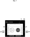
- Fig. 7 is an enlarged view of the remote controller image 72 in the second display region 100b.
- the remote controller image 72 is an image showing the remote controller 15.
- the remote controller image 72 may be an entire image of the remote controller 15, but may be a partial image of the remote controller 15 as in the present embodiment.
- the remote controller image 72 may be a partial image of the remote controller 15 in a case in which the remote controller image 72 includes an image of an individual operation switch of the remote controller 15 corresponding to the multifunctional switch 29 to which the balloon operation is assigned, here, images of the respective balloon operating parts 51 and 52 corresponding to the multifunctional switches 29e and 29d.
- the remote controller image 72 includes at least a first balloon operating part image 51P corresponding to the first balloon operating part 51 and a second balloon operating part image 52P corresponding to the second balloon operating part 52.
- the first balloon operating part 51 is provided with the first balloon state display part 53
- the second balloon operating part 52 is provided with the second balloon state display part 54. Therefore, the remote controller image 72 includes a first balloon state display part image 53P corresponding to the first balloon state display part 53, and a second balloon state display part image 54P corresponding to the second balloon state display part 54.
- the first balloon state display part image 53P includes an inflated state display part image 53AP corresponding to the inflated state display part 53A and a deflated state display part image 53BP corresponding to the deflated state display part 53B.
- the second balloon state display part image 54P includes an inflated state display part image 54AP corresponding to the inflated state display part 54A and a deflated state display part image 54BP corresponding to the deflated state display part 54B.
- a character string or an illustration indicating the endoscope 10 (that is, the first balloon 30) is displayed at a position near the first balloon operating part image 51P, and a character string or an illustration indicating the overtube 11 is displayed at a position near the second balloon operating part image 52P.
- the display control unit 80 reflects the type of the input operation on the remote controller image 72. For example, the display control unit 80 changes a display mode of the inflated state display part image 53AP in a case in which the inflation operation is performed with respect to the multifunctional switch 29e, and changes a display mode of the deflated state display part image 53BP in a case in which the deflation operation is performed with respect to the multifunctional switch 29e, based on the operation information input from the operating part 18.
- the display control unit 80 changes a display mode of the inflated state display part image 54AP in a case in which the inflation operation is performed with respect to the multifunctional switch 29d, and changes a display mode of the deflated state display part image 54BP in a case in which the deflation operation is performed with respect to the multifunctional switch 29d, based on the operation information input from the operating part 18.
- the change in the display modes of the inflated state display part images 53AP and 54AP and the deflated state display part images 53BP and 54BP referred to here means, for example, blinking individual images or changing a color, shape, or size of the individual images.
- Figs. 8A to 8D are explanatory diagrams for describing an example of changing the display modes of the inflated state display part images 53AP and 54AP and the deflated state display part images 53BP and 54BP in accordance with the inflation operation or the deflation operation with respect to the multifunctional switches 29e and 29d.
- the display control unit 80 changes the display modes of the deflated state display part image 53BP (the first balloon operating part image 51P) and the inflated state display part image 54AP (the second balloon operating part image 52P) in accordance with the deflation operation of the first balloon 30 with respect to the multifunctional switch 29e and the inflation operation of the second balloon 37 with respect to the multifunctional switch 29d.
- the display control unit 80 changes the display modes of the inflated state display part image 53AP (the first balloon operating part image 51P) and the deflated state display part image 54BP (the second balloon operating part image 52P) in accordance with the inflation operation of the first balloon 30 with respect to the multifunctional switch 29e and the deflation operation of the second balloon 37 with respect to the multifunctional switch 29d.
- the display control unit 80 changes the display modes of the inflated state display part images 53AP and 54AP (the first balloon operating part image 51P and the second balloon operating part image 52P) in accordance with the inflation operation of the respective balloons 30 and 37 with respect to the multifunctional switches 29e and 29d. Furthermore, as shown in Fig. 8D , the display control unit 80 changes the display modes of the deflated state display part images 53BP and 54BP (the first balloon operating part image 51P and the second balloon operating part image 52P) in accordance with the deflation operation of the respective balloons 30 and 37 with respect to the multifunctional switches 29e and 29d.
- the change in the display modes of the first balloon operating part image 51P (the inflated state display part image 53AP or the deflated state display part image 53BP) and the second balloon operating part image 52P (the inflated state display part image 54AP or the deflated state display part image 54BP) by the display control unit 80 is repeatedly executed.
- the change in the display mode of the first balloon operating part image 51P corresponding to the inflation operation and the deflation operation of the first balloon 30 with respect to the multifunctional switch 29e and the change in the display mode of the second balloon operating part image 52P corresponding to the inflation operation and the deflation operation of the second balloon 37 with respect to the multifunctional switch 29d are executed.
- the inflation operation and the deflation operation of the first balloon 30 with respect to the multifunctional switch 29e are individually reflected on the remote controller image 72
- the inflation operation and the deflation operation of the second balloon 37 with respect to the multifunctional switch 29d are individually reflected on the remote controller image 72. Accordingly, the operator can easily grasp what kind of operation has been performed on the multifunctional switches 29e and 29d in a state in which the operator gazes at the monitor 16.
- the operation with respect to the multifunctional switches 29e and 29d is reflected on the remote controller image 72 of the remote controller 15 used for the inflation operation and the deflation operation of the respective balloons 30 and 37. Accordingly, the operator can more intuitively grasp which switch of the remote controller 15 the operation with respect to the multifunctional switches 29e and 29d corresponds to, as compared with the case in which only the character string or the illustration indicating the inflation operation and the deflation operation of the respective balloons 30 and 37 is displayed on the monitor 16.
- Fig. 9 is an explanatory diagram showing an example of the endoscopy screen 100 displayed on the monitor 16 by the processor device 13 of the endoscope device 2 according to a second embodiment.
- the endoscope device 2 of the second embodiment displays information indicating pressure in the first balloon 30 and pressure in the second balloon 37 on the endoscopy screen 100.
- the endoscope device 2 according to the second embodiment has basically the same configuration as the endoscope device 2 according to the first embodiment except that the balloon controller 14 is provided with a pressure sensor 81 and the processor 13a of the processor device 13 functions as a pressure information acquisition unit 82. Therefore, the same reference numerals are given to those having the same function or configuration as those of the first embodiment, and the description thereof will be omitted.
- the pressure sensor 81 corresponds to a pressure detection sensor of the present invention, and is provided corresponding to the respective balloons 30 and 37 in the balloon controller 14.
- the pressure sensor 81 repeatedly executes detection of the pressure in the first balloon 30 and detection of the pressure in the second balloon 37 while the balloon controller 14 is being operated. Since a method of detecting the pressure in the respective balloons 30 and 37 by the pressure sensor 81 is a known technology (for example, see JP2005-261781A above), specific description thereof will be omitted here.
- the pressure sensor 81 may be provided in the endoscope 10 instead of being provided in the balloon controller 14. Then, each time the pressure sensor 81 detects the pressure in the respective balloons 30 and 37, a pressure detection result of the respective balloons 30 and 37 is repeatedly output to the processor device 13 via a communication cable (not shown).
- the pressure information acquisition unit 82 repeatedly executes acquisition of the pressure detection results of the respective balloons 30 and 37 from the pressure sensor 81 and output of the pressure detection results of the respective balloons 30 and 37 to the display control unit 80.
- the display control unit 80 sequentially generates the endoscopy screen 100 and sequentially outputs it to the monitor 16 based on the imaging signal sequentially input from the imaging unit 24a, the operation information of the multifunctional switches 29e and 29d sequentially input from the operating part 18, and the output of the pressure detection results of the respective balloons 30 and 37 input from the pressure information acquisition unit 82.
- the endoscopy screen 100 according to the second embodiment is basically the same as the endoscopy screen 100 according to the first embodiment except that the second display region 100b includes, in addition to the remote controller image 72, first pressure information 74 indicating the pressure in the first balloon 30 and the second pressure information 75 indicating the pressure in the second balloon 37.
- Fig. 10 is an enlarged view of the remote controller image 72, the first pressure information 74, and the second pressure information 75 according to the second embodiment.
- the display control unit 80 generates the first pressure information 74 based on the pressure detection result of the first balloon 30 input from the pressure information acquisition unit 82, and displays the first pressure information 74 at a position near the first balloon operating part image 51P.
- the display control unit 80 generates the second pressure information 75 based on the pressure detection result of the second balloon 37 input from the pressure information acquisition unit 82, and displays the second pressure information 75 at a position near the second balloon operating part image 52P.
- the first pressure information 74 includes an indicator 74A indicating magnitude of the pressure in the first balloon 30, and a pressure numerical value 74B indicating a numerical value of the pressure in the first balloon 30.
- the second pressure information 75 includes an indicator 75A indicating magnitude of the pressure in the second balloon 37, and a pressure numerical value 75B indicating a numerical value of the pressure in the second balloon 37.
- both the indicator 74A and the pressure numerical value 74B are displayed in the remote controller image 72 as the first pressure information 74, but only any one of the indicator 74A or the pressure numerical value 74B may be displayed.
- a display changeover switch (a function may be assigned to the multifunctional switch 29) (not shown) provided in the balloon controller 14, it is possible to switch between displaying both the indicator 74A and the pressure numerical value 74B, displaying only the indicator 74A, and displaying only the pressure numerical value 74B.
- the second pressure information 75 it may be possible to switch between displaying both the indicator 75A and the pressure numerical value 75B, displaying only the indicator 75A, and displaying only the pressure numerical value 75B.
- the display control unit 80 updates the display of the first pressure information 74 and the second pressure information 75 each time new pressure detection results of the respective balloons 30 and 37 are input from the pressure information acquisition unit 82.
- the operator can easily grasp the pressure in the respective balloons 30 and 37 in a state in which the operator gazes at the monitor 16.
- the operator can easily distinguish between the pressure in the first balloon 30 and the pressure in the second balloon 37.
- the first pressure information 74 and the second pressure information 75 are displayed at positions near the remote controller image 72, but the first pressure information 74 may be superimposed on the first balloon operating part image 51P, and the second pressure information 75 may be superimposed on the second balloon operating part image 52P. In addition, the first pressure information 74 and the second pressure information 75 may be displayed at any positions in the endoscopy screen 100.
- Fig. 11 is a configuration diagram of the endoscope device 2 according to a third embodiment.
- the emergency stop switch 48 provided on the front surface of the balloon controller 14 in a case of executing an emergency stop of the balloon controller 14 (an emergency stop of the inflation and deflation operation of the respective balloons 30 and 37), but the emergency stop operation may take time because both hands of the operator are full.
- a foot switch 110 for emergency stop is connected to the balloon controller 14.
- the endoscope device 2 according to the third embodiment has basically the same configuration as the endoscope device 2 according to each of the above-described embodiments except that the foot switch 110 is provided and the functions of the display control unit 80 are partially different. Therefore, the same reference numerals are given to those having the same function or configuration as those of each of the above-described embodiments, and the description thereof will be omitted.
- the foot switch 110 corresponds to the emergency stop switch of the present invention, and receives a foot operation (foot-step operation) by an operator's foot.
- the balloon controller 14 according to the third embodiment executes an emergency stop (a stop of the inflation and deflation operation of the respective balloons 30 and 37 or deflation of the respective balloons 30 and 37) in a case in which the foot operation is performed with respect to the foot switch 110.
- Two foot switches 110 may be connected to the balloon controller 14 so that the balloon controller 14 can individually execute the emergency stop of the respective balloons 30 and 37.
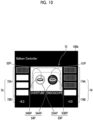
- Fig. 12 is an explanatory diagram for describing a display of warning information 79 by the monitor 16.
- the display control unit 80 causes the monitor 16 to display the warning information 79 indicating that the balloon controller 14 has been brought to an emergency stop in a case in which the foot operation is performed with respect to the foot switch 110, for example, superimposes the warning information 79 on the endoscopy screen 100. Accordingly, it is possible to notify that the balloon controller 14 has been brought to an emergency stop.
- the warning information 79 described above may be output as audio from a speaker (not shown).
- the emergency stop of the balloon controller 14 can be quickly executed even in a case in which both hands of the operator are full.
- the emergency stop of the balloon controller 14 is made possible by the foot switch 110, but for example, the function of the emergency stop switch may be provided in the remote controller 15 or the multifunctional switch 29.
- the change in the display modes of the first balloon operating part image 51P and the second balloon operating part image 52P is given as an example, the present invention is not limited thereto.
- the method of reflecting the type of the balloon operation on the remote controller image 72 is not particularly limited.
- a character string or an illustration indicating the type of the balloon operation input to the multifunctional switch 29 may be displayed on the remote controller image 72 or at a position near the remote controller image 72.
- the functions of the respective balloon operating parts 51 and 52 of the remote controller 15 are assigned to each multifunctional switch 29, but the functions of the stop button 57 as shown in Fig. 5 or the functions of other buttons and switches may be assigned to the multifunctional switches 29.
- the remote controller image 72 includes an image of the individual operation switch of the remote controller 15 corresponding to the multifunctional switch 29 to which the balloon operation is assigned.
- the functions of some individual operation switches of the remote controller 15 are assigned to the multifunctional switches 29 provided in the operating part 18, but the controller operation switch of the present invention is not limited to the multifunctional switch 29.
- the operating part 18 may be provided with dedicated operation switches having the functions of at least some individual operation switches of the remote controller 15.
- the multifunctional switch 29 or the dedicated operation switch may be provided in addition to the operating part 18 of the endoscope 10.
- the remote controller image 72, the first pressure information 74, and the second pressure information 75 are displayed on the endoscopy screen 100 only in the balloon operation presentation mode in which the multifunctional switch 29 is used, but the remote controller image 72, the first pressure information 74, and the second pressure information 75 may be displayed on the endoscopy screen 100 even in the normal mode. In this case, the operation on the remote controller 15 is reflected on the remote controller image 72.
- the present invention can also be applied to a single-balloon type endoscope device 2 (endoscope 10).
Landscapes
- Health & Medical Sciences (AREA)
- Life Sciences & Earth Sciences (AREA)
- Surgery (AREA)
- Engineering & Computer Science (AREA)
- Biomedical Technology (AREA)
- Molecular Biology (AREA)
- Pathology (AREA)
- Radiology & Medical Imaging (AREA)
- Nuclear Medicine, Radiotherapy & Molecular Imaging (AREA)
- Biophysics (AREA)
- Physics & Mathematics (AREA)
- Heart & Thoracic Surgery (AREA)
- Medical Informatics (AREA)
- Optics & Photonics (AREA)
- Animal Behavior & Ethology (AREA)
- General Health & Medical Sciences (AREA)
- Public Health (AREA)
- Veterinary Medicine (AREA)
- Signal Processing (AREA)
- Multimedia (AREA)
- Mechanical Engineering (AREA)
- Endoscopes (AREA)
Abstract
Description
- The present invention relates to an endoscope device that controls inflation and deflation of a balloon of an endoscope.
- In the related art, in a medical field, a procedure of inserting an insertion part of an endoscope into an intestinal tract (lumen) such as a large intestine and a small intestine to observe, diagnose, and treat an inner wall surface of the intestinal tract has been performed. Since the intestinal tract is complicatedly bent, it is difficult to transmit force to a distal end of the insertion part simply by pushing the insertion part of the endoscope, and it is difficult to insert the endoscope into a deep portion.
- Therefore, there is known a double-balloon type endoscope device in which balloons capable of inflating and deflating are respectively attached to the insertion part of the endoscope and a distal end portion of an overtube covering the insertion part (see
JP2016-137206A JP2005-296258A JP2006-149999A JP2007-111542A JP2005-261781A - In the endoscope device disclosed in
JP2016-137206A JP2005-296258A JP2006-149999A JP2007-111542A JP2005-261781A - In addition, in the endoscope device disclosed in
JP2006-149999A JP2007-111542A - Incidentally, in a case in which the switch provided in the operating part of the endoscope is operated to switch between inflation and deflation of each balloon as in the endoscope device disclosed in
JP2005-261781A - In addition, even in a case in which the balloon state image of each balloon is displayed on the monitor as in the endoscope device disclosed in
JP2006-149999A JP2007-111542A - The present invention has been made in view of such circumstances, and an object of the present invention is to provide an endoscope device that enables an operator to easily grasp which operation is being operated in a case in which the operator operates a controller operation switch provided in an endoscope.
- An endoscope device for achieving the object of the present invention comprises: a balloon; a balloon controller that controls inflation and deflation of the balloon; a remote controller that is connected to the balloon controller and operates the balloon controller, the remote controller being capable of inputting a plurality of types of balloon operations including an inflation operation and a deflation operation of the balloon; a controller operation switch for operating the balloon controller, the controller operation switch being provided in an endoscope and capable of inputting a plurality of types of the balloon operations that are common to the remote controller; and a processor, in which the processor is configured to: cause a monitor to display an endoscope image captured by the endoscope and a remote controller image which is an image of the remote controller; and in a case in which the balloon operation is input to the controller operation switch, reflect a type of the balloon operation input to the controller operation switch on the remote controller image displayed on the monitor.
- With the endoscope device, an operator can easily grasp what kind of balloon operation has been performed on the controller operation switch even in a state in which the operator gazes at the monitor.
- In the endoscope device according to another aspect of the present invention, the remote controller includes a plurality of types of individual operation switches corresponding to the plurality of types of balloon operations, the remote controller image includes images of the plurality of types of individual operation switches, and the processor is configured to, in a case in which the balloon operation is input to the controller operation switch, change a display mode of an image of the individual operation switch corresponding to the type of the balloon operation. Accordingly, it is possible to easily grasp which operation the operator is performing in a case in which the operator performs the balloon operation using the controller operation switch.
- In the endoscope device according to another aspect of the present invention, the balloon is provided at at least one of a distal end portion of an insertion part of the endoscope or a distal end portion of an overtube through which the insertion part is inserted.
- In the endoscope device according to another aspect of the present invention, the balloon is provided at the distal end portion of the insertion part and the distal end portion of the overtube, the balloon controller controls inflation and deflation of the balloon for each of the balloons, the remote controller is capable of inputting the balloon operation for each of the balloons, and the processor is configured to reflect the type of the balloon operation input to the controller operation switch on the remote controller image, for each of the balloons. Accordingly, even with a double-balloon type endoscope device, in a case in which the operator performs the balloon operation using the controller operation switch, it is possible to easily grasp which operation the operator is performing.
- In the endoscope device according to another aspect of the present invention, the endoscope device further comprises: an emergency stop switch for bringing the balloon controller to an emergency stop, in which the processor is configured to, in a case in which the emergency stop switch is operated, cause the monitor to display information indicating that the balloon controller has been brought to an emergency stop. Accordingly, it is possible to notify the operator that the balloon controller has been brought to an emergency stop.
- In the endoscope device according to another aspect of the present invention, the emergency stop switch is a foot switch connected to the balloon controller. Accordingly, even in a case in which both hands of the operator are full, it is possible to quickly perform an emergency stop operation of the balloon controller.
- In the endoscope device according to another aspect of the present invention, the endoscope device further comprises: a pressure detection sensor that repeatedly detects a pressure inside the balloon, in which the processor is configured to cause the monitor to display information indicating the pressure each time the pressure detection sensor detects the pressure. Accordingly, it is possible to easily grasp the pressure in the balloon in a state in which the operator gazes at the monitor.
- In the endoscope device according to another aspect of the present invention, the balloon is provided at a distal end portion of an insertion part of the endoscope and a distal end portion of an overtube through which the insertion part is inserted, the pressure detection sensor repeatedly detects the pressure for each of the balloons, and the processor is configured to cause the monitor to display the information indicating the pressure for each of the balloons. Accordingly, it is possible to easily grasp the pressure in each balloon in a state in which the operator gazes at the monitor.
- In the endoscope device according to another aspect of the present invention, the controller operation switch is provided in an operating part provided on a base end side of an insertion part of the endoscope.
- In the endoscope device according to another aspect of the present invention, the remote controller includes a plurality of types of individual operation switches corresponding to the plurality of types of balloon operations, the operating part is provided with a plurality of multifunctional switches to which a plurality of types of operations are capable of being selectively assigned, and the controller operation switch is the plurality of multifunctional switches to which functions of the plurality of types of individual operation switches are individually assigned. Accordingly, the present invention can be applied to an existing endoscope device comprising a multifunctional switch.
- According to the present invention, it is possible to easily grasp which operation an operator is performing in a case in which the operator operates a controller operation switch provided in an endoscope.
-
-
Fig. 1 is a configuration diagram of a double-balloon type endoscope device according to a first embodiment. -
Fig. 2 is a pipe line diagram of an endoscope device. -
Fig. 3 is a front view of a remote controller. -
Figs. 4A to 4D are explanatory diagrams for describing a display pattern of a first balloon state display part and a second balloon state display part of the remote controller. -
Fig. 5 is an explanatory diagram for describing assignment of functions of some switches of the remote controller to multifunctional switches. -
Fig. 6 is an explanatory diagram showing an example of an endoscopy screen displayed on a monitor in a balloon operation presentation mode by a processor device. -
Fig. 7 is an enlarged view of a remote controller image in a second display region. -
Figs. 8A to 8D are explanatory diagrams for describing an example of changing a display mode of an inflated state display part image and a deflated state display part image in accordance with an inflation operation or a deflation operation with respect to the multifunctional switches. -
Fig. 9 is an explanatory diagram showing an example of an endoscopy screen displayed on a monitor by a processor device of an endoscope device according to a second embodiment. -
Fig. 10 is an enlarged view of a remote controller image, first pressure information, and second pressure information according to the second embodiment. -
Fig. 11 is a configuration diagram of an endoscope device according to a third embodiment. -
Fig. 12 is an explanatory diagram for describing a display of warning information by a monitor. -
Fig. 1 is a configuration diagram of a double-balloontype endoscope device 2 according to a first embodiment. As shown inFig. 1 , anendoscope device 2 comprises anendoscope 10 which is an electronic endoscope with a balloon, anovertube 11 with a balloon, alight source device 12, aprocessor device 13, aballoon controller 14, aremote controller 15, and amonitor 16. - The
endoscope 10 comprises aflexible insertion part 17 and anoperating part 18 provided consecutively to a base end side of theinsertion part 17. - The
operating part 18 is used for an operator to perform an operation, and is also referred to as a hand operating part. Auniversal cable 19 is connected to theoperating part 18. Theuniversal cable 19 includes a signal cable (not shown), a light guide (not shown), a first supply/discharge pipe line 31 (seeFig. 2 ), and the like. Alight source connector 20 is provided at a distal end of theuniversal cable 19. - A
cable 21 is branched from thelight source connector 20, and theprocessor connector 22 is provided at a distal end thecable 21. Thelight source connector 20 is attachably and detachably connected to thelight source device 12, and theprocessor connector 22 is attachably and detachably connected to theprocessor device 13. - The
operating part 18 is provided with a plurality ofmultifunctional switches 29 in addition to a pair of knownangle knobs 23, an air supply/water supply button 27, asuction button 28, and a treatmenttool insertion part 18a. Each of themultifunctional switches 29, which will be described in detail below, can selectively assign a plurality of types of operations of theendoscope device 2, such as imaging of an area to be observed, switching of special light observation, and inflation and deflation of therespective balloons Fig. 5 ). The term "switch" in the present specification includes various known operating parts and operating members such as a button type, a lever type, and a touch sensor type. - The
insertion part 17 is inserted into a lumen (for example, a small intestine or a large intestine) of a subject. Theinsertion part 17 comprises adistal end portion 24, abendable portion 25, and asoft portion 26 from a distal end side to a base end side. - In addition to an
imaging unit 24a (seeFig. 6 ) that captures an image of an area to be observed in the lumen, thedistal end portion 24 comprises a known observation window, an illumination window for emitting illumination light supplied from thelight source device 12, a nozzle for air and water supplying, and a forceps port communicating with the treatmenttool insertion part 18a via a treatment tool channel (not shown) in theinsertion part 17, although not shown. Theimaging unit 24a is provided behind the observation window, and captures an observation image of the area to be observed through the observation window. In addition, a signal cable (not shown) is connected to theimaging unit 24a, and this signal cable is connected to theprocessor device 13 via theaforementioned insertion part 17, operatingpart 18,universal cable 19,light source connector 20,cable 21,processor connector 22, and the like. Accordingly, an imaging signal of the area to be observed imaged by theimaging unit 24a is output to theprocessor device 13 via the signal cable. - The
bendable portion 25 is remotely bent (angle operation) by rotating the pair of angle knobs 23 provided in the operatingpart 18. Accordingly, a distal end surface (observation window and illumination window) of thedistal end portion 24 can be directed in a desired direction. - The
soft portion 26 is provided consecutively to a base end of thebendable portion 25 and has flexibility. Thesoft portion 26 has a length of several meters to make thedistal end portion 24 reach a target position in the body. - A
first balloon 30 corresponding to the balloon of the present invention is attachably and detachably attached to thedistal end portion 24. Thefirst balloon 30 is formed in a substantially tubular shape of which an end portion is narrowed by an elastic material such as rubber, and has a balloon distal end portion and a balloon base end portion each having a small diameter, and a central swollen portion. Thedistal end portion 24 is inserted into thefirst balloon 30 such that thefirst balloon 30 is located at a predetermined position of thedistal end portion 24, and then, for example, a rubber ring is fitted into the balloon distal end portion and the balloon base end portion. Thus, thefirst balloon 30 is fixed to thedistal end portion 24. - The
overtube 11 attachably and detachably covers theinsertion part 17. Theovertube 11 comprises agrip portion 35 gripped by the operator, amain body portion 36, and asecond balloon 37 corresponding to the balloon of the present invention. - The
grip portion 35 is a tubular body made of a hard material such as plastic. Themain body portion 36 is formed in a substantially tubular shape by a flexible material such as polyurethane, and is externally fitted and fixed to a distal end side of thegrip portion 35. - The
second balloon 37 is formed in a substantially tubular shape of which an end portion is narrowed by an elastic material such as rubber, and has a balloon distal end portion and a balloon base end portion each having a small diameter, and a central swollen portion. Thesecond balloon 37 covers an outer peripheral surface of a distal end of themain body portion 36, and is fixed to themain body portion 36 by, for example, winding a thread around the balloon distal end portion and the balloon base end portion and applying an adhesive thereon. -
Fig. 2 is a pipe line diagram of theendoscope device 2. InFig. 2 , theendoscope 10 and theovertube 11 are shown in a simplified manner. - As shown in
Fig. 2 andFig. 1 described above, theendoscope 10 is provided with a first supply/discharge pipe line 31 for supplying and sucking air into the inside of thefirst balloon 30. The first supply/discharge pipe line 31 is a flexible tube, and is inserted into theinsertion part 17, the operatingpart 18, theuniversal cable 19, and thelight source connector 20. - A distal end side of the first supply/
discharge pipe line 31 communicates with anopening 32 for a balloon formed on an outer peripheral surface of thedistal end portion 24. Theopening 32 is formed at an attaching/detaching position of thefirst balloon 30 on the outer peripheral surface of thedistal end portion 24. In addition, an endoscope-side cap 33 is provided on a base end side of the first supply/discharge pipe line 31. - The endoscope-
side cap 33 is formed integrally with thelight source connector 20. The endoscope-side cap 33 is connected to theballoon controller 14 via atube 34. Accordingly, by theballoon controller 14 described below, air can be supplied to the inside of thefirst balloon 30 to inflate thefirst balloon 30 or, conversely, air can be sucked from the inside of thefirst balloon 30 to deflate thefirst balloon 30, via thetube 34, the endoscope-side cap 33, the first supply/discharge pipe line 31, and theopening 32. Note that the term "air" as used herein is gas for inflating the first balloon 30 (also including thesecond balloon 37 described below), and a type (component) thereof is not particularly limited. In addition, various fluids including a liquid such as water may be used instead of "air". - A
supply pipe line 38 and a second supply/discharge pipe line 39 are formed inside themain body portion 36 of theovertube 11 in an axial direction thereof. Thesupply pipe line 38 is a hole through which theinsertion part 17 of theendoscope 10 is inserted, and an inner diameter thereof is formed to be slightly larger than an outer diameter of theinsertion part 17. - In a case in which the
overtube 11 is used, a lubricant such as water is supplied to an inner peripheral surface (gap between theinsertion part 17 and the main body portion 36) of thesupply pipe line 38 to reduce friction between theinsertion part 17 and themain body portion 36. The lubricant is injected from a connector 40 (seeFig. 1 ) communicating with thesupply pipe line 38 by a syringe (not shown) or the like. - The second supply/
discharge pipe line 39 is a pipe line for supplying and sucking air to thesecond balloon 37, and is provided in a pipe wall of thesupply pipe line 38. A distal end side of the second supply/discharge pipe line 39 communicates with anopening 41 for a balloon formed on an outer peripheral surface of themain body portion 36. Theopening 41 is formed at an attaching/detaching position of thesecond balloon 37 on the outer peripheral surface of themain body portion 36. In addition, atube 42 having a small diameter is provided consecutively to a base end side of the second supply/discharge pipe line 39, and aconnector 43 is provided consecutively to a base end side of thetube 42. - A
tube 44 is connected to theconnector 43, and thetube 44 is further connected to theballoon controller 14. Accordingly, by theballoon controller 14 described below, air can be supplied to the inside of thesecond balloon 37 to inflate thesecond balloon 37 or, conversely, air can be sucked from the inside of thesecond balloon 37 to deflate thesecond balloon 37, via thetube 44, theconnector 43, thetube 42, the second supply/discharge pipe line 39, and theopening 41. - Returning to
Fig. 1 , theballoon controller 14 supplies and sucks air to and from therespective balloons first balloon 30 of theendoscope 10 and thesecond balloon 37 of theovertube 11. Theballoon controller 14 is provided with a pump, a solenoid valve, and the like. In addition, aremote controller 15 is electrically connected to theballoon controller 14 via acable 45. - Further, some of a plurality of
multifunctional switches 29 provided in the operatingpart 18 are electrically connected to theballoon controller 14 via a signal cable (not shown). - The
balloon controller 14 individually controls the inflation and deflation of therespective balloons remote controller 15 or themultifunctional switch 29 by the operator. For example, theballoon controller 14 individually supplies air to therespective balloons respective balloons respective balloons balloon controller 14 individually sucks air from therespective balloons respective balloons respective balloons - A
display part 46, apower switch 47, anemergency stop switch 48, atube connecting portion 49, and the like are provided on a front surface of theballoon controller 14. - In a case in which the
respective balloons display part 46 displays a pressure value of theballoons respective balloons display part 46 in a case in which an abnormality, such as tear in therespective balloons display part 46, theballoon controller 14 outputs a buzzer sound from a speaker (not shown). - The
power switch 47 is used to turn on and off the power of theballoon controller 14. Theemergency stop switch 48 is used for an emergency stop of the balloon controller 14 (an emergency stop of the inflation and deflation operation of therespective balloons 30 and 37). The emergency stop referred to here includes, for example, stopping the inflation and deflation operation of therespective balloons respective balloons respective balloons - The
aforementioned tubes tube connecting portion 49. Although not shown, thetube connecting portion 49 is provided with a backflow prevention unit. The backflow prevention unit prevents a body fluid or the like from flowing into theballoon controller 14 in a case in which therespective balloons -
Fig. 3 is a front view of theremote controller 15. As shown inFig. 3 , theremote controller 15 is used for the input of a plurality of types of balloon operations including an inflation operation and a deflation operation of therespective balloons - The
remote controller 15 has a shape appropriate for being gripped by the operator, and is provided with, on a front surface, a firstballoon operating part 51, a secondballoon operating part 52, a first balloonstate display part 53, a second balloonstate display part 54, a firstballoon pause button 55, a secondballoon pause button 56, astop button 57, and the like. The firstballoon operating part 51, the secondballoon operating part 52, the firstballoon pause button 55, the secondballoon pause button 56, and thestop button 57 are used for the plurality of types of balloon operations described above, and correspond to a plurality of types of individual operation switches of the present invention. - The first
balloon operating part 51 is positioned on a right side of theremote controller 15 in a case in which theremote controller 15 is viewed from the front, and is a circular toggle switch for performing the inflation operation and the deflation operation of thefirst balloon 30 with respect to theballoon controller 14. In the present embodiment, the firstballoon operating part 51 is also formed to be black (indicated by hatching in the figure) in accordance with the general color (black) of theendoscope 10. - Each time the first
balloon operating part 51 is pushed, the inflation operation of thefirst balloon 30 and the deflation operation of thefirst balloon 30 are alternately input to theballoon controller 14. Accordingly, in a case in which the inflation operation of thefirst balloon 30 is input, theballoon controller 14 supplies air to thefirst balloon 30 to inflate thefirst balloon 30, and, conversely, in a case in which the deflation operation of thefirst balloon 30 is input, theballoon controller 14 sucks air from thefirst balloon 30 to deflate thefirst balloon 30. - The first balloon
state display part 53 is provided in the firstballoon operating part 51, and has an inflatedstate display part 53A and a deflatedstate display part 53B. The inflatedstate display part 53A displays an inflated state in which thefirst balloon 30 is inflated by supplying air from theballoon controller 14 to thefirst balloon 30. The deflatedstate display part 53B displays a deflated state in which thefirst balloon 30 is deflated by sucking air from thefirst balloon 30. - The inflated
state display part 53A is disposed along an outer periphery of the firstballoon operating part 51, and is a ring-shaped state display part that indicates an inflated state of thefirst balloon 30. The deflatedstate display part 53B is disposed inside the inflatedstate display part 53A (on the first balloon operating part 51), and is a flat-shape state display part that indicates a deflated state of thefirst balloon 30. Since the detailed configuration of the inflatedstate display part 53A and the deflatedstate display part 53B is a known technology (seeJP2016-137206A - The inflated
state display part 53A switches to a display state (light emitting state) in a case in which thefirst balloon 30 is in an inflated state, and switches to a non-display state (non-light emitting state) in a case in which thefirst balloon 30 is in a deflated state. On the other hand, the deflatedstate display part 53B switches to a display state (light emitting state) in a case in which thefirst balloon 30 is in a deflated state, and switches to a non-display state (non-light emitting state) in a case in which thefirst balloon 30 is in an inflated state. Therefore, any one of the inflatedstate display part 53A or the deflatedstate display part 53B is in a display state, and the other is in a non-display state. - The second
balloon operating part 52 is provided on a left side of theremote controller 15 in a case in which theremote controller 15 is viewed from the front, and located at a position symmetrical to the firstballoon operating part 51 with respect to a center line of theremote controller 15. The secondballoon operating part 52 is a circular toggle switch for performing the inflation operation and the deflation operation of thesecond balloon 37 with respect to theballoon controller 14. In the present embodiment, the secondballoon operating part 52 is also formed to be white in accordance with the general color (white) of theovertube 11. - Each time the second
balloon operating part 52 is pushed, the inflation operation of thesecond balloon 37 and the deflation operation of thesecond balloon 37 are alternately input to theballoon controller 14. Accordingly, in a case in which the inflation operation of thesecond balloon 37 is input, theballoon controller 14 supplies air to thesecond balloon 37 to inflate thesecond balloon 37, and, conversely, in a case in which the deflation operation of thesecond balloon 37 is input, theballoon controller 14 sucks air from thesecond balloon 37 to deflate thesecond balloon 37. - The second balloon
state display part 54 has an inflatedstate display part 54A and a deflatedstate display part 54B. The inflatedstate display part 54A is provided along an outer periphery of the secondballoon operating part 52, and is a ring-shaped state display part that indicates an inflated state in which thesecond balloon 37 is inflated. The deflatedstate display part 54B is provided inside the inflatedstate display part 54A (on the second balloon operating part 52), and is a flat-shape state display part that indicates a deflated state in which thesecond balloon 37 is deflated. - The inflated
state display part 54A switches to a display state (light emitting state) in a case in which thesecond balloon 37 is in an inflated state, and switches to a non-display state (non-light emitting state) in a case in which thesecond balloon 37 is in a deflated state. On the other hand, the deflatedstate display part 54B switches to a display state (light emitting state) in a case in which thesecond balloon 37 is in a deflated state, and switches to a non-display state (non-light emitting state) in a case in which thesecond balloon 37 is in an inflated state. Therefore, any one of the inflatedstate display part 54A or the deflatedstate display part 54B is in a display state, and the other is in a non-display state. - In this way, by referring to the display of the inflated
state display part 53A and the deflatedstate display part 53B and the display of the inflatedstate display part 54A and the deflatedstate display part 54B, the operator can discriminate whether therespective balloons -
Fig. 3 shows an example of theremote controller 15, in which a shape of theremote controller 15, a shape and arrangement of each button (switch), and a function of each button (switch) can be appropriately changed. -
Figs. 4A to 4D are explanatory diagrams for describing a display pattern of the first balloonstate display part 53 and the second balloonstate display part 54 of theremote controller 15. For example, as shown inFig. 4A , in a case in which the inflatedstate display part 53A is in a non-display state, the deflatedstate display part 53B is in a display state, the inflatedstate display part 54A is in a display state, and the deflatedstate display part 54B is in a non-display state, the operator can discriminate that thefirst balloon 30 is in a deflated state and thesecond balloon 37 is in an inflated state. - In addition, as shown in
Fig. 4B , in a case in which the inflatedstate display part 53A is in a display state, the deflatedstate display part 53B is in a non-display state, the inflatedstate display part 54A is in a non-display state, and the deflatedstate display part 54B is in a display state, the operator can discriminate that thefirst balloon 30 is in an inflated state and thesecond balloon 37 is in a deflated state. - Further, as shown in
Fig. 4C , in a case in which both of the inflatedstate display parts state display parts balloons Fig. 4D , in a case in which both of the inflatedstate display parts state display parts balloons - Returning to
Fig. 3 , a character string of "ENDOSCOPE" meaning theendoscope 10 is attached below the firstballoon operating part 51, and a character string of "OVERTUBE" meaning theovertube 11 is below the secondballoon operating part 52. Note that the present invention is not limited to this, and illustrations or the like showing theendoscope 10 and theovertube 11 may be attached. - The first
balloon pause button 55 is provided below the character string of "ENDOSCOPE", and the secondballoon pause button 56 is provided below the character string of "OVERTUBE". The firstballoon pause button 55 and the secondballoon pause button 56 are rectangular push buttons. A character string of "PAUSE" meaning a pause is attached between the firstballoon pause button 55 and the secondballoon pause button 56. - The first
balloon pause button 55 inputs a pause operation of an inflated state and a deflated state of thefirst balloon 30 to theballoon controller 14. Theballoon controller 14 that has received the input of the pause operation maintains thefirst balloon 30 in an inflated state by maintaining the pressure of the air supplied to thefirst balloon 30 at a constant value, or maintains thefirst balloon 30 in a deflated state by maintaining the pressure of the air sucked from thefirst balloon 30 at a constant value. - The second
balloon pause button 56 inputs a pause operation of an inflated state and a deflated state of thesecond balloon 37 to theballoon controller 14. Theballoon controller 14 that has received the input of the pause operation maintains thesecond balloon 37 in an inflated state by maintaining the pressure of the air supplied to thesecond balloon 37 at a constant value, or maintains thesecond balloon 37 in a deflated state by maintaining the pressure of the air sucked from thesecond balloon 37 at a constant value. - The
stop button 57 is provided below the firstballoon pause button 55 and the secondballoon pause button 56 and on the center line of theremote controller 15. Thestop button 57 is a rectangular push button. A character string of "STOP" meaning a stop is attached above thestop button 57. - The
stop button 57 outputs a stop operation of the aforementioned buzzer sound (including an error code display) to theballoon controller 14. Theballoon controller 14 stops the output of the buzzer sound in a case in which the stop operation is input while the buzzer sound is being output. In addition, instead of using thestop button 57 for the stop operation of the buzzer sound, thestop button 57 may be used for the aforementioned emergency stop of the inflation and deflation operation of therespective balloons -
Fig. 5 is an explanatory diagram for describing assignment of functions of some switches of theremote controller 15 to the multifunctional switches 29.Reference numerals Fig. 5 are enlarged views of the operatingpart 18 viewed from different directions, andreference numeral 5C is a front view of theremote controller 15. - As shown in
Fig. 5 , the operatingpart 18 is provided with five (or other than five) multifunctional switches 29 (hereinafter, referred to asmultifunctional switches 29a to 29e as appropriate). Themultifunctional switch 29 can input a plurality of types of balloon operations common to theremote controller 15. In the present embodiment, in a simulating manner, a function of the firstballoon operating part 51 is assigned to themultifunctional switch 29e, and a function of the secondballoon operating part 52 is assigned to themultifunctional switch 29d. Accordingly, themultifunctional switch 29e functions as a toggle switch similar to the aforementioned firstballoon operating part 51, and themultifunctional switch 29d functions as a toggle switch similar to the aforementioned secondballoon operating part 52. - Therefore, each time the
multifunctional switch 29e is pushed, the inflation operation of thefirst balloon 30 and the deflation operation of thefirst balloon 30 are alternately input to theballoon controller 14 via a signal cable (not shown). In addition, each time themultifunctional switch 29d is pushed, the inflation operation of thesecond balloon 37 and the deflation operation of thesecond balloon 37 are alternately input to theballoon controller 14 via a signal cable (not shown). Accordingly, by pushing themultifunctional switches respective balloons multifunctional switch 29e (inflation operation and deflation operation of the first balloon 30) and operation information of themultifunctional switch 29d (inflation operation and deflation operation of the second balloon 37) are alto sequentially input to theprocessor device 13 via a signal cable (not shown). - A function of the
stop button 57 may be assigned to themultifunctional switch 29c. In addition, a function as an imaging button for executing the capturing of an image of the area to be observed by theimaging unit 24a (seeFig. 6 ) is assigned to themultifunctional switch 29a. In addition, a function as a changeover switch for switching observation modes such as normal observation and special light observation is assigned to the multifunctional switch 29b. - Returning to
Fig. 1 , theprocessor device 13 causes themonitor 16 to display anendoscopy screen 100 including an endoscope image 70 (seeFig. 6 ) of the area to be observed based on the imaging signal of the observed part sequentially input from theimaging unit 24a (seeFig. 6 ) via a signal cable (not shown) and theprocessor connector 22. - The
processor device 13 comprises an arithmetic circuit configured of various processors, a memory, and the like. Various processors include a central processing unit (CPU), a graphics processing unit (GPU), an application specific integrated circuit (ASIC), and a programmable logic device [for example, simple programmable logic devices (SPLD), complex programmable logic device (CPLD), and field programmable gate arrays (FPGA)]. Note that various functions of theprocessor device 13 may be realized by one processor or may be realized by a plurality of processors of the same type or different types. - The
processor device 13 has a normal mode and a balloon operation presentation mode as a display mode for displaying theendoscopy screen 100 on themonitor 16. The normal mode is a display mode selected in a case in which theremote controller 15 is used for the input of the balloon operations (inflation operation, deflation operation, and the like) of therespective balloons - The balloon operation presentation mode is a display mode selected in a case in which the multifunctional switch 29 (here, in particular, the
multifunctional switches respective balloons first balloon 30 are performed by using themultifunctional switch 29e, or the inflation operation and the deflation operation of thesecond balloon 37 are performed by using themultifunctional switch 29d, it is difficult to instantly grasp which balloon operation is being performed because the operator gazes at themonitor 16. Therefore, in a case in which the balloon operation presentation mode is selected, theprocessor device 13 causes themonitor 16 to display, together with theendoscope image 70, aremote controller image 72 in which the operator can easily identify the type of the balloon operation input to themultifunctional switch 29. -
Fig. 6 is an explanatory diagram showing an example of the endoscopy screen 100 (theendoscope image 70 and the remote controller image 72) displayed on themonitor 16 in a balloon operation presentation mode by theprocessor device 13. InFig. 6 , a case in which only themultifunctional switches Fig. 6 , in a balloon operation presentation mode, aprocessor 13a of theprocessor device 13 functions as adisplay control unit 80 by executing a program read out from a memory (not shown). - The
display control unit 80 sequentially generates theendoscopy screen 100 and sequentially outputs it to themonitor 16 based on the imaging signal sequentially input from theimaging unit 24a via a signal cable (not shown) and the operation information of themultifunctional switches part 18 via a signal cable (not shown). - The
endoscopy screen 100 is broadly divided into afirst display region 100a and asecond display region 100b. Thefirst display region 100a displays theendoscope image 70 of a known area to be observed, which is generated by thedisplay control unit 80 based on the imaging signal. Thesecond display region 100b displays theremote controller image 72 generated by thedisplay control unit 80 based on the operation information of themultifunctional switches - In the present embodiment, the
endoscope image 70 and theremote controller image 72 are displayed in thefirst display region 100a and thesecond display region 100b, which are different from each other, in theendoscopy screen 100, but for example, theremote controller image 72 may be superimposed (superposed) on theendoscope image 70. Alternatively, theremote controller image 72 may be displayed in a display window different from a display window of theendoscope image 70 by a picture-in-picture method. -
Fig. 7 is an enlarged view of theremote controller image 72 in thesecond display region 100b. As shown inFig. 7 , theremote controller image 72 is an image showing theremote controller 15. Here, theremote controller image 72 may be an entire image of theremote controller 15, but may be a partial image of theremote controller 15 as in the present embodiment. Specifically, theremote controller image 72 may be a partial image of theremote controller 15 in a case in which theremote controller image 72 includes an image of an individual operation switch of theremote controller 15 corresponding to themultifunctional switch 29 to which the balloon operation is assigned, here, images of the respectiveballoon operating parts multifunctional switches - The
remote controller image 72 includes at least a first balloon operatingpart image 51P corresponding to the firstballoon operating part 51 and a second balloon operatingpart image 52P corresponding to the secondballoon operating part 52. Here, in the present embodiment, the firstballoon operating part 51 is provided with the first balloonstate display part 53, and the secondballoon operating part 52 is provided with the second balloonstate display part 54. Therefore, theremote controller image 72 includes a first balloon statedisplay part image 53P corresponding to the first balloonstate display part 53, and a second balloon statedisplay part image 54P corresponding to the second balloonstate display part 54. - The first balloon state
display part image 53P includes an inflated state display part image 53AP corresponding to the inflatedstate display part 53A and a deflated state display part image 53BP corresponding to the deflatedstate display part 53B. In addition, the second balloon statedisplay part image 54P includes an inflated state display part image 54AP corresponding to the inflatedstate display part 54A and a deflated state display part image 54BP corresponding to the deflatedstate display part 54B. - In the
remote controller image 72, similarly to theremote controller 15, a character string or an illustration indicating the endoscope 10 (that is, the first balloon 30) is displayed at a position near the first balloon operatingpart image 51P, and a character string or an illustration indicating theovertube 11 is displayed at a position near the second balloon operatingpart image 52P. - Each time the inflation operation or the deflation operation is input to the
multifunctional switches display control unit 80 reflects the type of the input operation on theremote controller image 72. For example, thedisplay control unit 80 changes a display mode of the inflated state display part image 53AP in a case in which the inflation operation is performed with respect to themultifunctional switch 29e, and changes a display mode of the deflated state display part image 53BP in a case in which the deflation operation is performed with respect to themultifunctional switch 29e, based on the operation information input from the operatingpart 18. - In addition, for example, the
display control unit 80 changes a display mode of the inflated state display part image 54AP in a case in which the inflation operation is performed with respect to themultifunctional switch 29d, and changes a display mode of the deflated state display part image 54BP in a case in which the deflation operation is performed with respect to themultifunctional switch 29d, based on the operation information input from the operatingpart 18. - The change in the display modes of the inflated state display part images 53AP and 54AP and the deflated state display part images 53BP and 54BP referred to here means, for example, blinking individual images or changing a color, shape, or size of the individual images.
-
Figs. 8A to 8D are explanatory diagrams for describing an example of changing the display modes of the inflated state display part images 53AP and 54AP and the deflated state display part images 53BP and 54BP in accordance with the inflation operation or the deflation operation with respect to themultifunctional switches - As shown in
Fig. 8A , thedisplay control unit 80 changes the display modes of the deflated state display part image 53BP (the first balloon operatingpart image 51P) and the inflated state display part image 54AP (the second balloon operatingpart image 52P) in accordance with the deflation operation of thefirst balloon 30 with respect to themultifunctional switch 29e and the inflation operation of thesecond balloon 37 with respect to themultifunctional switch 29d. - In addition, as shown in
Fig. 8B , thedisplay control unit 80 changes the display modes of the inflated state display part image 53AP (the first balloon operatingpart image 51P) and the deflated state display part image 54BP (the second balloon operatingpart image 52P) in accordance with the inflation operation of thefirst balloon 30 with respect to themultifunctional switch 29e and the deflation operation of thesecond balloon 37 with respect to themultifunctional switch 29d. - Further, as shown in
Fig. 8C , thedisplay control unit 80 changes the display modes of the inflated state display part images 53AP and 54AP (the first balloon operatingpart image 51P and the second balloon operatingpart image 52P) in accordance with the inflation operation of therespective balloons multifunctional switches Fig. 8D , thedisplay control unit 80 changes the display modes of the deflated state display part images 53BP and 54BP (the first balloon operatingpart image 51P and the second balloon operatingpart image 52P) in accordance with the deflation operation of therespective balloons multifunctional switches - Hereinafter, each time the operator inputs the inflation operation or the deflation operation of the
respective balloons multifunctional switches part image 51P (the inflated state display part image 53AP or the deflated state display part image 53BP) and the second balloon operatingpart image 52P (the inflated state display part image 54AP or the deflated state display part image 54BP) by thedisplay control unit 80 is repeatedly executed. - As described above, in the first embodiment, the change in the display mode of the first balloon operating
part image 51P corresponding to the inflation operation and the deflation operation of thefirst balloon 30 with respect to themultifunctional switch 29e and the change in the display mode of the second balloon operatingpart image 52P corresponding to the inflation operation and the deflation operation of thesecond balloon 37 with respect to themultifunctional switch 29d are executed. As a result, the inflation operation and the deflation operation of thefirst balloon 30 with respect to themultifunctional switch 29e are individually reflected on theremote controller image 72, and the inflation operation and the deflation operation of thesecond balloon 37 with respect to themultifunctional switch 29d are individually reflected on theremote controller image 72. Accordingly, the operator can easily grasp what kind of operation has been performed on themultifunctional switches monitor 16. - In addition, in the present embodiment, the operation with respect to the
multifunctional switches remote controller image 72 of theremote controller 15 used for the inflation operation and the deflation operation of therespective balloons remote controller 15 the operation with respect to themultifunctional switches respective balloons monitor 16. -
Fig. 9 is an explanatory diagram showing an example of theendoscopy screen 100 displayed on themonitor 16 by theprocessor device 13 of theendoscope device 2 according to a second embodiment. Theendoscope device 2 of the second embodiment displays information indicating pressure in thefirst balloon 30 and pressure in thesecond balloon 37 on theendoscopy screen 100. - As shown in
Fig. 9 , theendoscope device 2 according to the second embodiment has basically the same configuration as theendoscope device 2 according to the first embodiment except that theballoon controller 14 is provided with apressure sensor 81 and theprocessor 13a of theprocessor device 13 functions as a pressure information acquisition unit 82. Therefore, the same reference numerals are given to those having the same function or configuration as those of the first embodiment, and the description thereof will be omitted. - The
pressure sensor 81 corresponds to a pressure detection sensor of the present invention, and is provided corresponding to therespective balloons balloon controller 14. Thepressure sensor 81 repeatedly executes detection of the pressure in thefirst balloon 30 and detection of the pressure in thesecond balloon 37 while theballoon controller 14 is being operated. Since a method of detecting the pressure in therespective balloons pressure sensor 81 is a known technology (for example, seeJP2005-261781A pressure sensor 81 may be provided in theendoscope 10 instead of being provided in theballoon controller 14. Then, each time thepressure sensor 81 detects the pressure in therespective balloons respective balloons processor device 13 via a communication cable (not shown). - The pressure information acquisition unit 82 repeatedly executes acquisition of the pressure detection results of the
respective balloons pressure sensor 81 and output of the pressure detection results of therespective balloons display control unit 80. - The
display control unit 80 according to the second embodiment sequentially generates theendoscopy screen 100 and sequentially outputs it to themonitor 16 based on the imaging signal sequentially input from theimaging unit 24a, the operation information of themultifunctional switches part 18, and the output of the pressure detection results of therespective balloons - The
endoscopy screen 100 according to the second embodiment is basically the same as theendoscopy screen 100 according to the first embodiment except that thesecond display region 100b includes, in addition to theremote controller image 72,first pressure information 74 indicating the pressure in thefirst balloon 30 and thesecond pressure information 75 indicating the pressure in thesecond balloon 37. -
Fig. 10 is an enlarged view of theremote controller image 72, thefirst pressure information 74, and thesecond pressure information 75 according to the second embodiment. As shown inFig. 10 , thedisplay control unit 80 generates thefirst pressure information 74 based on the pressure detection result of thefirst balloon 30 input from the pressure information acquisition unit 82, and displays thefirst pressure information 74 at a position near the first balloon operatingpart image 51P. In addition, thedisplay control unit 80 generates thesecond pressure information 75 based on the pressure detection result of thesecond balloon 37 input from the pressure information acquisition unit 82, and displays thesecond pressure information 75 at a position near the second balloon operatingpart image 52P. - The
first pressure information 74 includes anindicator 74A indicating magnitude of the pressure in thefirst balloon 30, and a pressurenumerical value 74B indicating a numerical value of the pressure in thefirst balloon 30. Thesecond pressure information 75 includes anindicator 75A indicating magnitude of the pressure in thesecond balloon 37, and a pressurenumerical value 75B indicating a numerical value of the pressure in thesecond balloon 37. - In the second embodiment, both the
indicator 74A and the pressurenumerical value 74B are displayed in theremote controller image 72 as thefirst pressure information 74, but only any one of theindicator 74A or the pressurenumerical value 74B may be displayed. For example, by operating a display changeover switch (a function may be assigned to the multifunctional switch 29) (not shown) provided in theballoon controller 14, it is possible to switch between displaying both theindicator 74A and the pressurenumerical value 74B, displaying only theindicator 74A, and displaying only the pressurenumerical value 74B. Similarly, for thesecond pressure information 75, it may be possible to switch between displaying both theindicator 75A and the pressurenumerical value 75B, displaying only theindicator 75A, and displaying only the pressurenumerical value 75B. - Hereinafter, the
display control unit 80 updates the display of thefirst pressure information 74 and thesecond pressure information 75 each time new pressure detection results of therespective balloons - As described above, in the second embodiment, by displaying the
first pressure information 74 and thesecond pressure information 75 on themonitor 16, the operator can easily grasp the pressure in therespective balloons monitor 16. In addition, by displaying thefirst pressure information 74 at a position near the first balloon operatingpart image 51P and displaying thesecond pressure information 75 at a position near the second balloon operatingpart image 52P, the operator can easily distinguish between the pressure in thefirst balloon 30 and the pressure in thesecond balloon 37. - In the second embodiment, the
first pressure information 74 and thesecond pressure information 75 are displayed at positions near theremote controller image 72, but thefirst pressure information 74 may be superimposed on the first balloon operatingpart image 51P, and thesecond pressure information 75 may be superimposed on the second balloon operatingpart image 52P. In addition, thefirst pressure information 74 and thesecond pressure information 75 may be displayed at any positions in theendoscopy screen 100. -
Fig. 11 is a configuration diagram of theendoscope device 2 according to a third embodiment. In each of the above-described embodiments, it is necessary to operate theemergency stop switch 48 provided on the front surface of theballoon controller 14 in a case of executing an emergency stop of the balloon controller 14 (an emergency stop of the inflation and deflation operation of therespective balloons 30 and 37), but the emergency stop operation may take time because both hands of the operator are full. - Therefore, in the
endoscope device 2 according to the third embodiment, afoot switch 110 for emergency stop is connected to theballoon controller 14. Theendoscope device 2 according to the third embodiment has basically the same configuration as theendoscope device 2 according to each of the above-described embodiments except that thefoot switch 110 is provided and the functions of thedisplay control unit 80 are partially different. Therefore, the same reference numerals are given to those having the same function or configuration as those of each of the above-described embodiments, and the description thereof will be omitted. - The
foot switch 110 corresponds to the emergency stop switch of the present invention, and receives a foot operation (foot-step operation) by an operator's foot. Theballoon controller 14 according to the third embodiment executes an emergency stop (a stop of the inflation and deflation operation of therespective balloons respective balloons 30 and 37) in a case in which the foot operation is performed with respect to thefoot switch 110. Two foot switches 110 may be connected to theballoon controller 14 so that theballoon controller 14 can individually execute the emergency stop of therespective balloons -
Fig. 12 is an explanatory diagram for describing a display of warninginformation 79 by themonitor 16. As shown inFig. 12 , thedisplay control unit 80 according to the third embodiment causes themonitor 16 to display the warninginformation 79 indicating that theballoon controller 14 has been brought to an emergency stop in a case in which the foot operation is performed with respect to thefoot switch 110, for example, superimposes the warninginformation 79 on theendoscopy screen 100. Accordingly, it is possible to notify that theballoon controller 14 has been brought to an emergency stop. In addition to or instead of displaying the warninginformation 79 on themonitor 16, the warninginformation 79 described above may be output as audio from a speaker (not shown). - As described above, in the third embodiment, since an emergency stop of the
balloon controller 14 can be performed by thefoot switch 110, the emergency stop of theballoon controller 14 can be quickly executed even in a case in which both hands of the operator are full. - In the third embodiment, the emergency stop of the
balloon controller 14 is made possible by thefoot switch 110, but for example, the function of the emergency stop switch may be provided in theremote controller 15 or themultifunctional switch 29. - In each of the above-described embodiments, as a method of reflecting the type of the balloon operation (inflation operation, deflation operation) input to the
multifunctional switches remote controller image 72, the change in the display modes of the first balloon operatingpart image 51P and the second balloon operatingpart image 52P is given as an example, the present invention is not limited thereto. As long as the operator can grasp the type of the balloon operation input to themultifunctional switch 29, the method of reflecting the type of the balloon operation on theremote controller image 72 is not particularly limited. For example, a character string or an illustration indicating the type of the balloon operation input to themultifunctional switch 29 may be displayed on theremote controller image 72 or at a position near theremote controller image 72. - In each of the above-described embodiments, the functions of the respective
balloon operating parts remote controller 15 are assigned to eachmultifunctional switch 29, but the functions of thestop button 57 as shown inFig. 5 or the functions of other buttons and switches may be assigned to the multifunctional switches 29. In this case, theremote controller image 72 includes an image of the individual operation switch of theremote controller 15 corresponding to themultifunctional switch 29 to which the balloon operation is assigned. - In each of the above-described embodiments, the functions of some individual operation switches of the
remote controller 15 are assigned to themultifunctional switches 29 provided in the operatingpart 18, but the controller operation switch of the present invention is not limited to themultifunctional switch 29. For example, the operatingpart 18 may be provided with dedicated operation switches having the functions of at least some individual operation switches of theremote controller 15. Further, themultifunctional switch 29 or the dedicated operation switch may be provided in addition to the operatingpart 18 of theendoscope 10. - In each of the above-described embodiments, the
remote controller image 72, thefirst pressure information 74, and thesecond pressure information 75 are displayed on theendoscopy screen 100 only in the balloon operation presentation mode in which themultifunctional switch 29 is used, but theremote controller image 72, thefirst pressure information 74, and thesecond pressure information 75 may be displayed on theendoscopy screen 100 even in the normal mode. In this case, the operation on theremote controller 15 is reflected on theremote controller image 72. - Although the double-balloon
type endoscope device 2 has been described in each of the above-described embodiments, the present invention can also be applied to a single-balloon type endoscope device 2 (endoscope 10). -
- 2: endoscope device
- 10: endoscope
- 11: overtube
- 12: light source device
- 13: processor device
- 13a: processor
- 14: balloon controller
- 15: remote controller
- 16: monitor
- 17: insertion part
- 18: operating part
- 18a: treatment tool insertion part
- 19: universal cable
- 20: light source connector
- 21: cable
- 22: processor connector
- 23: angle knob
- 24: distal end portion
- 24a: imaging unit
- 25: bendable portion
- 26: soft portion
- 27: air supply/water supply button
- 28: suction button
- 29: multifunctional switch
- 29a, 29b, 29c, 29d, 29e: multifunctional switch
- 30: first balloon
- 31: first supply/discharge pipe line
- 32: opening
- 33: endoscope-side cap
- 34: tube
- 35: grip portion
- 36: main body portion
- 37: second balloon
- 38: supply pipe line
- 39: second supply/discharge pipe line
- 40: connector
- 41: opening
- 42: tube
- 43: connector
- 44: tube
- 45: cable
- 46: display part
- 47: power switch
- 48: emergency stop switch
- 49: tube connecting portion
- 51: first balloon operating part
- 5 IP: first balloon operating part image
- 52: second balloon operating part
- 52P: second balloon operating part image
- 53: first balloon state display part
- 53A: inflated state display part
- 53AP: inflated state display part image
- 53B: deflated state display part
- 53BP: deflated state display part image
- 53P: first balloon state display part image
- 54: second balloon state display part
- 54A: inflated state display part
- 54AP: inflated state display part image
- 54B: deflated state display part
- 54BP: deflated state display part image
- 54P: second balloon state display part image
- 55: first balloon pause button
- 56: second balloon pause button
- 57: stop button
- 70: endoscope image
- 72: remote controller image
- 74: first pressure information
- 74A: indicator
- 74B: pressure numerical value
- 75: second pressure information
- 75A: indicator
- 75B: pressure numerical value
- 79: warning information
- 80: display control unit
- 81: pressure sensor
- 82: pressure information acquisition unit
- 100: endoscopy screen
- 100a: first display region
- 100b: second display region
- 110: foot switch
Claims (10)
- An endoscope device comprising:a balloon;a balloon controller that controls inflation and deflation of the balloon;a remote controller that is connected to the balloon controller and operates the balloon controller, the remote controller being capable of inputting a plurality of types of balloon operations including an inflation operation and a deflation operation of the balloon;a controller operation switch for operating the balloon controller, the controller operation switch being provided in an endoscope and capable of inputting a plurality of types of the balloon operations that are common to the remote controller; anda processor,wherein the processor is configured to:cause a monitor to display an endoscope image captured by the endoscope and a remote controller image which is an image of the remote controller; andin a case in which the balloon operation is input to the controller operation switch, reflect a type of the balloon operation input to the controller operation switch on the remote controller image displayed on the monitor.
- The endoscope device according to claim 1,wherein the remote controller includes a plurality of types of individual operation switches corresponding to the plurality of types of balloon operations,the remote controller image includes images of the plurality of types of individual operation switches, andthe processor is configured to, in a case in which the balloon operation is input to the controller operation switch, change a display mode of an image of the individual operation switch corresponding to the type of the balloon operation.
- The endoscope device according to claim 1 or 2,
wherein the balloon is provided at at least one of a distal end portion of an insertion part of the endoscope or a distal end portion of an overtube through which the insertion part is inserted. - The endoscope device according to claim 3,wherein the balloon is provided at the distal end portion of the insertion part and the distal end portion of the overtube,the balloon controller controls inflation and deflation of the balloon for each of the balloons,the remote controller is capable of inputting the balloon operation for each of the balloons, andthe processor is configured to reflect the type of the balloon operation input to the controller operation switch on the remote controller image, for each of the balloons.
- The endoscope device according to any one of claims 1 to 4, further comprising:an emergency stop switch for bringing the balloon controller to an emergency stop,wherein the processor is configured to, in a case in which the emergency stop switch is operated, cause the monitor to display information indicating that the balloon controller has been brought to an emergency stop.
- The endoscope device according to claim 5,
wherein the emergency stop switch is a foot switch connected to the balloon controller. - The endoscope device according to any one of claims 1 to 6, further comprising:a pressure detection sensor that repeatedly detects a pressure inside the balloon,wherein the processor is configured to cause the monitor to display information indicating the pressure each time the pressure detection sensor detects the pressure.
- The endoscope device according to claim 7,wherein the balloon is provided at a distal end portion of an insertion part of the endoscope and a distal end portion of an overtube through which the insertion part is inserted,the pressure detection sensor repeatedly detects the pressure for each of the balloons,
andthe processor is configured to cause the monitor to display the information indicating the pressure for each of the balloons. - The endoscope device according to any one of claims 1 to 8,
wherein the controller operation switch is provided in an operating part provided on a base end side of an insertion part of the endoscope. - The endoscope device according to claim 9,wherein the remote controller includes a plurality of types of individual operation switches corresponding to the plurality of types of balloon operations,the operating part is provided with a plurality of multifunctional switches to which a plurality of types of operations are capable of being selectively assigned, andthe controller operation switch is the plurality of multifunctional switches to which functions of the plurality of types of individual operation switches are individually assigned.
Applications Claiming Priority (1)
| Application Number | Priority Date | Filing Date | Title |
|---|---|---|---|
| JP2022093823A JP7764320B2 (en) | 2022-06-09 | 2022-06-09 | Endoscopic Devices |
Publications (2)
| Publication Number | Publication Date |
|---|---|
| EP4289333A1 true EP4289333A1 (en) | 2023-12-13 |
| EP4289333B1 EP4289333B1 (en) | 2026-01-14 |
Family
ID=86387154
Family Applications (1)
| Application Number | Title | Priority Date | Filing Date |
|---|---|---|---|
| EP23174044.0A Active EP4289333B1 (en) | 2022-06-09 | 2023-05-17 | Endoscope device |
Country Status (4)
| Country | Link |
|---|---|
| US (1) | US20230397796A1 (en) |
| EP (1) | EP4289333B1 (en) |
| JP (1) | JP7764320B2 (en) |
| CN (1) | CN117204802A (en) |
Families Citing this family (2)
| Publication number | Priority date | Publication date | Assignee | Title |
|---|---|---|---|---|
| JP7076561B2 (en) * | 2018-09-04 | 2022-05-27 | 富士フイルム株式会社 | Overtube |
| USD1066659S1 (en) * | 2021-09-24 | 2025-03-11 | Adaptivendo Llc | Endoscope handle |
Citations (6)
| Publication number | Priority date | Publication date | Assignee | Title |
|---|---|---|---|---|
| JP2005007030A (en) * | 2003-06-20 | 2005-01-13 | Fuji Photo Optical Co Ltd | Endoscope instrument |
| JP2005261781A (en) | 2004-03-19 | 2005-09-29 | Olympus Corp | Double balloon type endoscope system |
| JP2005296258A (en) | 2004-04-09 | 2005-10-27 | Olympus Corp | Endoscope balloon controller |
| US20060116586A1 (en) * | 2004-11-05 | 2006-06-01 | Fujinon Corporation | Balloon controller for endoscopic apparatus |
| JP2007111542A (en) | 2006-11-28 | 2007-05-10 | Fujinon Corp | Endoscope apparatus |
| JP2016137206A (en) | 2015-01-29 | 2016-08-04 | 富士フイルム株式会社 | Remote controller for balloon control device and endoscope system |
Family Cites Families (1)
| Publication number | Priority date | Publication date | Assignee | Title |
|---|---|---|---|---|
| JP3874299B2 (en) | 2005-02-07 | 2007-01-31 | フジノン株式会社 | Balloon control device for endoscope apparatus |
-
2022
- 2022-06-09 JP JP2022093823A patent/JP7764320B2/en active Active
-
2023
- 2023-05-16 US US18/317,929 patent/US20230397796A1/en active Pending
- 2023-05-17 EP EP23174044.0A patent/EP4289333B1/en active Active
- 2023-05-31 CN CN202310638526.1A patent/CN117204802A/en active Pending
Patent Citations (9)
| Publication number | Priority date | Publication date | Assignee | Title |
|---|---|---|---|---|
| JP2005007030A (en) * | 2003-06-20 | 2005-01-13 | Fuji Photo Optical Co Ltd | Endoscope instrument |
| JP2005261781A (en) | 2004-03-19 | 2005-09-29 | Olympus Corp | Double balloon type endoscope system |
| JP2005296258A (en) | 2004-04-09 | 2005-10-27 | Olympus Corp | Endoscope balloon controller |
| US20070055101A1 (en) * | 2004-04-09 | 2007-03-08 | Olympus Corporation | Endoscope balloon control device |
| US20060116586A1 (en) * | 2004-11-05 | 2006-06-01 | Fujinon Corporation | Balloon controller for endoscopic apparatus |
| JP2006149999A (en) | 2004-11-05 | 2006-06-15 | Fujinon Corp | Balloon control device for endoscope apparatus |
| JP2007111542A (en) | 2006-11-28 | 2007-05-10 | Fujinon Corp | Endoscope apparatus |
| JP2016137206A (en) | 2015-01-29 | 2016-08-04 | 富士フイルム株式会社 | Remote controller for balloon control device and endoscope system |
| US20160220097A1 (en) * | 2015-01-29 | 2016-08-04 | Fujifilm Corporation | Remote controller for balloon controlling device and endoscope system |
Also Published As
| Publication number | Publication date |
|---|---|
| EP4289333B1 (en) | 2026-01-14 |
| JP2023180472A (en) | 2023-12-21 |
| JP7764320B2 (en) | 2025-11-05 |
| CN117204802A (en) | 2023-12-12 |
| US20230397796A1 (en) | 2023-12-14 |
Similar Documents
| Publication | Publication Date | Title |
|---|---|---|
| CN1946330B (en) | Endoscopic Balloon Control Device | |
| JP6374327B2 (en) | Remote controller for balloon control device and endoscope system | |
| EP4289333B1 (en) | Endoscope device | |
| EP1804642B1 (en) | Automated control of irrigation and aspiration in a single-use endoscope | |
| JP5563852B2 (en) | Overtube with balloon and endoscope system | |
| JP3834820B2 (en) | Balloon control device for endoscope apparatus | |
| CN102469930B (en) | Endoscope system | |
| JP3874298B2 (en) | Balloon control device for endoscope apparatus | |
| JP5422634B2 (en) | Endoscope insertion aid and endoscope system | |
| JP2005205181A (en) | Balloon control device | |
| CN102469912A (en) | Endoscope system | |
| US8409078B2 (en) | Endoscope | |
| JP2016055103A (en) | Hood for endoscope and endoscope system | |
| JP4727224B2 (en) | Air supply device | |
| JP2006174882A (en) | Air sending device | |
| JP2003010105A (en) | Endoscope system | |
| JP3874299B2 (en) | Balloon control device for endoscope apparatus | |
| JP2008206693A (en) | Balloon for medical instrument | |
| JP2006167299A (en) | Air sending device | |
| JP2006129948A (en) | Gas feeding device | |
| JP2005334472A (en) | Medical system | |
| JP2007330628A (en) | Balloon for medical equipment, and medical equipment provided with the same | |
| JP2024017278A (en) | Endoscope connection structure | |
| WO2024257236A1 (en) | Endoscope, endoscope cap | |
| KR100848771B1 (en) | Endoscope balloon control device |
Legal Events
| Date | Code | Title | Description |
|---|---|---|---|
| PUAI | Public reference made under article 153(3) epc to a published international application that has entered the european phase |
Free format text: ORIGINAL CODE: 0009012 |
|
| STAA | Information on the status of an ep patent application or granted ep patent |
Free format text: STATUS: THE APPLICATION HAS BEEN PUBLISHED |
|
| AK | Designated contracting states |
Kind code of ref document: A1 Designated state(s): AL AT BE BG CH CY CZ DE DK EE ES FI FR GB GR HR HU IE IS IT LI LT LU LV MC ME MK MT NL NO PL PT RO RS SE SI SK SM TR |
|
| STAA | Information on the status of an ep patent application or granted ep patent |
Free format text: STATUS: REQUEST FOR EXAMINATION WAS MADE |
|
| 17P | Request for examination filed |
Effective date: 20240612 |
|
| RBV | Designated contracting states (corrected) |
Designated state(s): AL AT BE BG CH CY CZ DE DK EE ES FI FR GB GR HR HU IE IS IT LI LT LU LV MC ME MK MT NL NO PL PT RO RS SE SI SK SM TR |
|
| GRAP | Despatch of communication of intention to grant a patent |
Free format text: ORIGINAL CODE: EPIDOSNIGR1 |
|
| STAA | Information on the status of an ep patent application or granted ep patent |
Free format text: STATUS: GRANT OF PATENT IS INTENDED |
|
| INTG | Intention to grant announced |
Effective date: 20250826 |
|
| RAP3 | Party data changed (applicant data changed or rights of an application transferred) |
Owner name: FUJIFILM CORPORATION |
|
| GRAS | Grant fee paid |
Free format text: ORIGINAL CODE: EPIDOSNIGR3 |
|
| GRAA | (expected) grant |
Free format text: ORIGINAL CODE: 0009210 |
|
| STAA | Information on the status of an ep patent application or granted ep patent |
Free format text: STATUS: THE PATENT HAS BEEN GRANTED |
|
| P01 | Opt-out of the competence of the unified patent court (upc) registered |
Free format text: CASE NUMBER: UPC_APP_0012917_4289333/2025 Effective date: 20251111 |
|
| AK | Designated contracting states |
Kind code of ref document: B1 Designated state(s): AL AT BE BG CH CY CZ DE DK EE ES FI FR GB GR HR HU IE IS IT LI LT LU LV MC ME MK MT NL NO PL PT RO RS SE SI SK SM TR |
|
| REG | Reference to a national code |
Ref country code: CH Ref legal event code: F10 Free format text: ST27 STATUS EVENT CODE: U-0-0-F10-F00 (AS PROVIDED BY THE NATIONAL OFFICE) Effective date: 20260114 Ref country code: GB Ref legal event code: FG4D |
|
| REG | Reference to a national code |
Ref country code: DE Ref legal event code: R096 Ref document number: 602023010630 Country of ref document: DE |
|
| REG | Reference to a national code |
Ref country code: IE Ref legal event code: FG4D |