EP4288767B1 - Testvorrichtung und testverfahren - Google Patents
Testvorrichtung und testverfahren Download PDFInfo
- Publication number
- EP4288767B1 EP4288767B1 EP23703616.5A EP23703616A EP4288767B1 EP 4288767 B1 EP4288767 B1 EP 4288767B1 EP 23703616 A EP23703616 A EP 23703616A EP 4288767 B1 EP4288767 B1 EP 4288767B1
- Authority
- EP
- European Patent Office
- Prior art keywords
- light sources
- stripe
- image acquisition
- light
- preferably less
- Prior art date
- Legal status (The legal status is an assumption and is not a legal conclusion. Google has not performed a legal analysis and makes no representation as to the accuracy of the status listed.)
- Active
Links
Images


Classifications
-
- G—PHYSICS
- G01—MEASURING; TESTING
- G01N—INVESTIGATING OR ANALYSING MATERIALS BY DETERMINING THEIR CHEMICAL OR PHYSICAL PROPERTIES
- G01N21/00—Investigating or analysing materials by the use of optical means, i.e. using sub-millimetre waves, infrared, visible or ultraviolet light
- G01N21/84—Systems specially adapted for particular applications
- G01N21/88—Investigating the presence of flaws or contamination
- G01N21/95—Investigating the presence of flaws or contamination characterised by the material or shape of the object to be examined
- G01N21/958—Inspecting transparent materials or objects, e.g. windscreens
-
- G—PHYSICS
- G01—MEASURING; TESTING
- G01M—TESTING STATIC OR DYNAMIC BALANCE OF MACHINES OR STRUCTURES; TESTING OF STRUCTURES OR APPARATUS, NOT OTHERWISE PROVIDED FOR
- G01M11/00—Testing of optical apparatus; Testing structures by optical methods not otherwise provided for
- G01M11/02—Testing optical properties
- G01M11/0207—Details of measuring devices
-
- G—PHYSICS
- G01—MEASURING; TESTING
- G01M—TESTING STATIC OR DYNAMIC BALANCE OF MACHINES OR STRUCTURES; TESTING OF STRUCTURES OR APPARATUS, NOT OTHERWISE PROVIDED FOR
- G01M11/00—Testing of optical apparatus; Testing structures by optical methods not otherwise provided for
- G01M11/02—Testing optical properties
- G01M11/0242—Testing optical properties by measuring geometrical properties or aberrations
- G01M11/0257—Testing optical properties by measuring geometrical properties or aberrations by analyzing the image formed by the object to be tested
-
- G—PHYSICS
- G01—MEASURING; TESTING
- G01M—TESTING STATIC OR DYNAMIC BALANCE OF MACHINES OR STRUCTURES; TESTING OF STRUCTURES OR APPARATUS, NOT OTHERWISE PROVIDED FOR
- G01M11/00—Testing of optical apparatus; Testing structures by optical methods not otherwise provided for
- G01M11/02—Testing optical properties
- G01M11/0242—Testing optical properties by measuring geometrical properties or aberrations
- G01M11/0257—Testing optical properties by measuring geometrical properties or aberrations by analyzing the image formed by the object to be tested
- G01M11/0264—Testing optical properties by measuring geometrical properties or aberrations by analyzing the image formed by the object to be tested by using targets or reference patterns
-
- G—PHYSICS
- G01—MEASURING; TESTING
- G01M—TESTING STATIC OR DYNAMIC BALANCE OF MACHINES OR STRUCTURES; TESTING OF STRUCTURES OR APPARATUS, NOT OTHERWISE PROVIDED FOR
- G01M11/00—Testing of optical apparatus; Testing structures by optical methods not otherwise provided for
- G01M11/02—Testing optical properties
- G01M11/0242—Testing optical properties by measuring geometrical properties or aberrations
- G01M11/0278—Detecting defects of the object to be tested, e.g. scratches or dust
-
- G—PHYSICS
- G01—MEASURING; TESTING
- G01N—INVESTIGATING OR ANALYSING MATERIALS BY DETERMINING THEIR CHEMICAL OR PHYSICAL PROPERTIES
- G01N21/00—Investigating or analysing materials by the use of optical means, i.e. using sub-millimetre waves, infrared, visible or ultraviolet light
- G01N21/84—Systems specially adapted for particular applications
- G01N21/88—Investigating the presence of flaws or contamination
- G01N21/8806—Specially adapted optical and illumination features
- G01N2021/8829—Shadow projection or structured background, e.g. for deflectometry
- G01N2021/8832—Structured background, e.g. for transparent objects
-
- G—PHYSICS
- G01—MEASURING; TESTING
- G01N—INVESTIGATING OR ANALYSING MATERIALS BY DETERMINING THEIR CHEMICAL OR PHYSICAL PROPERTIES
- G01N21/00—Investigating or analysing materials by the use of optical means, i.e. using sub-millimetre waves, infrared, visible or ultraviolet light
- G01N21/84—Systems specially adapted for particular applications
- G01N21/88—Investigating the presence of flaws or contamination
- G01N21/8806—Specially adapted optical and illumination features
- G01N2021/8835—Adjustable illumination, e.g. software adjustable screen
-
- G—PHYSICS
- G01—MEASURING; TESTING
- G01N—INVESTIGATING OR ANALYSING MATERIALS BY DETERMINING THEIR CHEMICAL OR PHYSICAL PROPERTIES
- G01N21/00—Investigating or analysing materials by the use of optical means, i.e. using sub-millimetre waves, infrared, visible or ultraviolet light
- G01N21/84—Systems specially adapted for particular applications
- G01N21/88—Investigating the presence of flaws or contamination
- G01N21/95—Investigating the presence of flaws or contamination characterised by the material or shape of the object to be examined
- G01N21/958—Inspecting transparent materials or objects, e.g. windscreens
- G01N2021/9583—Lenses
Definitions
- the invention relates to a Testing device for detecting defects of transparent test specimens, in particular of ophthalmological lenses, with an illumination device for transilluminating test specimens to be examined and with an image acquisition device for imaging the test specimen transilluminated by the illumination device.
- the invention further relates to a testing method for detecting a defect of a transparent specimen, in particular of an ophthalmological lens; comprising:
- test specimens especially those that have an optical effect, such as ophthalmic lenses like spectacle lenses
- quality control is often very time-consuming and is carried out visually in the absence of automated processes that would be suitable for detecting defects safely and reliably.
- This manual or visual inspection of the test specimens is carried out by trained employees who have to check each test specimen individually for the presence of defects during production.
- Typical defects that appear on and/or in the test specimens can be divided into three different classes according to their visual effect. These are light-absorbing defects, light-refracting defects and light-diffracting defects.
- the defects contained in the test specimens can also belong to several of the aforementioned classes.
- the problem associated with manual or visual testing is that the result of such testing is subjective and can be influenced by various factors.
- the quality and thus the result of the quality control strongly depends on the daily form of the test person, his or her state of mind, the time of the check or other factors.
- the examination is very tiring for the employee due to the monotony of the task, so that the result is often not reproducible.
- it has proven to be disadvantageous that the result of the review varies from employee to employee, making it difficult to achieve uniform results. In order to further homogenize the results of the review, a not inconsiderable amount of training is therefore necessary, the results of which have to be verified within the framework of measurement system analyses. In addition, a very long period of several months is often required to train the inspecting staff, which means that an expansion of production capacities at short notice is not possible.
- a transparent test specimen is understood to mean in particular a test specimen made of a material that can be used for the production of optical components, i.e. in particular a test specimen made of an optical material according to DIN EN ISO 13666:2019-12, section 3.3.1.
- a transparent test specimen can be a blank according to DIN EN ISO 13666:2019-12, section 3.8.1, i.e. a piece of an optical material with an optically finished surface for the manufacture of an ophthalmic lens, or it can also be a finished ophthalmic lens according to DIN EN ISO 13666:2019-12, section 3.8.7, i.e. an ophthalmic lens with two optically finished surfaces, in which the edge processing has already been carried out or still has to be carried out.
- the transparent test specimens can also be other blanks or pressed parts or also precision-ground parts.
- a comparable testing device is also known from US 8,081,840 B2 , in which stripe patterns are shown by means of a display, which also serves as an illumination device, and which shine through the transparent test specimen, which is arranged between the illumination device and the camera, and are recorded by the camera.
- the content depicted on the display is controlled in order to change the position of the stripes between the individual images.
- EP 1 016 860 B1 describes an inspection device in which only the outer edge of contact lenses is inspected for defects.
- the other areas of the contact lenses to be examined are shaded for this purpose, so that the light from the light source only penetrates the contact lens in the area of the outermost edge area and is guided from there to the camera.
- a testing device for the examination of contact lenses is known from EP 1 248 092 A1 , in which two images are recorded with different illumination situations. These images are then evaluated in a downstream step in order to be able to draw conclusions about any defects present in or on the contact lenses.
- a testing device and a testing method according to the type mentioned at the beginning is already known from WO 2019/243568 A1 , which is considered to be the closest prior art.
- a display is used as the illumination device, on which geometric patterns with different brightness values, more precisely stripe patterns with alternating bright or white and dark stripes, are shown, which are then detected by means of a camera, wherein the transparent test specimen is arranged between the display serving as the illumination device and the camera.
- the display transilluminates the test specimen, and the camera captures a corresponding image of the transilluminated test specimen.
- the position of the light and dark stripes on the monitor is then changed between the individual images.
- the captured stripe recording - or stripe images - can then be combined in a recombination step to form an overall image and evaluated for defect detection, as described in detail in WO 2019/243568 A1 , for example.
- WO 2019/243568 A1 has shown that it is disadvantageous that the individual pixels of the display are also imaged by the camera, which has a negative influence on the automatic detection of defects and thus has a disadvantageous effect on the inspection result.
- the testing device for detecting defects of transparent test specimens, in particular of ophthalmological lenses, comprises an illumination device for transilluminating test specimens to be examined and an image acquisition device for imaging the test specimen transilluminated by the illumination device.
- the illumination device comprises a plurality of light sources, which are linearly moveable by a first drive in a first direction for generating a stripe pattern.
- the acquisition duration of the image acquisition device can be adjusted in such a way that the light emitted by each of the light sources, moved linearly by the first drive in the first directions, is detected as a light stripe.
- the light sources are moved linearly in a common direction while the image of the test specimen illuminated by the light sources is captured by the image acquisition device.
- the acquisition duration of the image acquisition device is adapted to the velocity of the linear adjustment of the light sources in such a way that the light sources are not captured or imaged by the image acquisition device as individual points, but rather as light stripes, whereby adjacent light stripes are each separated by a dark strip. Since each light stripe is ultimately generated by a single light source, it is simultaneously ensured that when the stripe patterns are generated, the stripes each have a homogeneous and for test specimen with a rather flat curvature- at a constant speed, especially within the light stripe - a consistently bright light distribution, which improves the detection of defects of the test specimen.
- the test specimen is positioned between the illumination device and the image acquisition device so that the transparent test specimen is transilluminated by the illumination device from one side - for example, from the rear surface- and the other side - for example, the front surface - is captured by the image acquisition device.
- the front surface of the test specimen is according to DIN EN ISO 13666:2019-12, section 3.2.13, the surface of the lens intended to be fitted away from the eye which, when used as intended, and the back surface is according to DIN EN ISO 13666:2019-12, section 3.2.14, the surface of the lens intended to be fitted nearer to the eye side.
- the testing device comprises an illumination device for transilluminating test specimens to be examined and an image acquisition device for imaging the test specimen transilluminated by the illumination device.
- the illumination device comprises a plurality of light sources, which are arranged on a light carrier which is linearly moveable in a first direction for generating a stripe pattern.
- the acquisition duration of the image acquisition device can be adjusted in such a way that the light emitted by each of the light sources arranged on the light carrier and moved linearly in the first direction is detected as a light stripe.
- the testing device for detecting defects of transparent test specimens, in particular of ophthalmological lenses, which is not covered by the claims comprises an illumination device for transilluminating test specimens to be examined and an image acquisition device for imaging the test specimen transilluminated by the illumination device.
- the illumination device comprises a plurality of point light sources, which are designed as LEDs and which are linearly moveable in a first direction for generating a stripe pattern.
- the acquisition duration of the image acquisition device can be adjusted in such a way that the light emitted by each of the light sources moved linearly in the first direction is detected as a light stripe.
- a first drive is provided for linear adjustment, i.e. movement of the light sources in a first direction and/or in that a second drive is provided for linear adjustment of the light sources in a second direction substantially perpendicular to the first direction, which are in each case substantially perpendicular to an observation path of the image acquisition device.
- the first drive which linearly adjusts, i.e. moves, the light sources in the first direction, serves to generate the stripe pattern.
- the second drive which adjusts the light sources in the second direction, which is perpendicular to the first direction, serves to reposition the light sources between the individual stripe recordings.
- a stripe recording means an image captured by the image acquisition device, which might be a camera, of the transilluminated test specimen while the light sources are linearly adjusted in the first direction.
- the first drive also ensures that the light sources of the illumination device can be adjusted as uniformly as possible in a linear manner, thereby ensuring that the light stripes are generated uniformly.
- the change in the position of the light stripes in the second direction between two stripe recordings is affected by the fact that the distances between adjacent light sources are ultimately very small.
- the linear adjustment of the light sources in the second direction between the stripe recordings is then solved by deactivating the previously activated - i.e. illuminating - light sources during the next stripe recording and activating one of the adjacent light sources in each case.
- deactivating the previously activated - i.e. illuminating - light sources during the next stripe recording and activating one of the adjacent light sources in each case.
- only every x th light source is operated when creating the first stripe recording and the x+1 th light source is operated when creating the second stripe recording. This has the advantage that there is no need for the second drive.
- the light sources are arranged on a light carrier.
- the light carrier extends along the second direction.
- the light sources can be positioned on the light carrier in a particularly simple but at the same time precise manner.
- the light carrier is formed as a cuboid whose longitudinal axis extends parallel to the second direction.
- the light carrier can be designed as a one-dimensional grid, i.e., as a thin and narrow structure or cuboid.
- the light sources are arranged at an equidistant distance from one another.
- the stripe recordings captured are as uniform as possible, which simplifies the downstream evaluation for defect detection.
- the equidistant distance between the light sources results in an equidistant distance also for the light stripes originating from the light sources.
- knowing the distance between the light stripes allows to linearly adjust the position of the light sources in the second direction in an appropriate manner between each stripe recording in order to ensure the covering of the whole test specimen with the different light stripes.
- the distance D between adjacent light sources is greater than 3 mm, preferably greater than 5 mm and further preferably less than 12 mm, preferably less than 10 mm and particularly preferably 7 mm. If the distance between adjacent light sources is too small or too large, this has a negative effect on the testing device according to the invention and on the detection of the defects in the test specimen. For example, if the distance is too large, the number of required stripe recordings increases. If, on the other hand, the distance between adjacent light sources is too small, the dark stripes between two light stripes are over-illuminated and a separation of neighboring light stripes is no longer possible. Also, there might be a superposition of light from two different spatial directions, so that defects may no longer be visible. In addition, the number of light sources must be increased in a detrimental manner.
- the number of light sources is greater than 1, preferably greater than 8 and particularly preferably greater than 12 and further preferably less than 50, preferably less than 30 and most preferably 23.
- the number of light sources is greater than 1, preferably greater than 8 and particularly preferably greater than 12 and further preferably less than 50, preferably less than 30 and most preferably 23.
- the velocity of the first drive for moving the light sources in the first direction and/or the velocity of the second drive for moving the light sources in the second direction is greater than 1,000 mm/s, preferably greater than 2,000 mm/s, particularly preferably greater than 2,500 mm/s and further preferably less than 5,000 mm/s, preferably less than 4,000 mm/s, particularly preferably less than 3,500 mm/s and most preferably 3,000 mm/s.
- the velocity of the first drive for moving the light sources in the first direction and/or the velocity of the second drive for moving the light sources in the second direction is greater than 1,000 mm/s, preferably greater than 2,000 mm/s, particularly preferably greater than 2,500 mm/s and further preferably less than 5,000 mm/s, preferably less than 4,000 mm/s, particularly preferably less than 3,500 mm/s and most preferably 3,000 mm/s.
- the complexity of the equipment so that a velocity of 3,000 mm/s has proved to be a very good compromise.
- the velocity of the second drive is lower than the velocity of the first drive used for the linear adjustment of the light sources in the first direction.
- the linear displacement of the light sources in the second direction is significantly lower than the linear displacement in the first direction, so that a lower velocity in the linear displacement of the light sources in the second direction between the stripe recordings does not entail a significantly longer duration of the defect detection.
- the acceleration of the first and/or the acceleration of the second drive is greater than 10,000 mm/s 2 , preferably greater than 15,000 mm/s 2 , particularly preferably greater than 18,000 mm/s 2 and further preferably less than 30,000 mm/s 2 , preferably less than 25,000 mm/s 2 , particularly preferably less than 22,000 mm/s 2 and most preferably 20,000 mm/s 2 .
- an acceleration of 20,000 mm/s 2 has proven to be a good compromise. At these high acceleration values, it is particularly ensured that the capture of the stripe recordings is not adversely affected by areas where the speed of the light sources in the first direction would be too low, causing the brightness to increase locally.
- the image acquisition device comprises a camera with a telecentric lens.
- a telecentric lens provides a limited acceptance angle to facilitate to visualize the differences in brightness caused by the defects, especially by weakly refractive defects. Furthermore, this ensures that the image captures are still accurate even if the test specimen should move out of focus. In addition, the depth of field is increased and even less distortion is achieved.
- a collimator lens is arranged between the illumination device and the test specimen, whereby the light impinging on the test specimen is directed in a preferred way.
- the method comprises (a) an image acquisition step in which a plurality of stripe recordings are captured by an image acquisition device and are generated with the aid of an illumination device; (b) a reconstruction step, in which an overall image is reconstructed from the stripe recordings; and (c) a defect detection step in which a possible defect is detected from the overall image.
- the illumination device for generating a stripe pattern comprises a plurality of light sources, which are linearly moved in a first direction by a first drive in the image acquisition step. In order to capture the stripe pattern the acquisition duration of the image acquisition device is set in such a way that the light emitted by the linearly moved light sources is respectively detected as a light stripe.
- the method comprises (a) an image acquisition step in which a plurality of stripe recordings are captured by an image acquisition device and are generated with the aid of an illumination device; (b) a reconstruction step, in which an overall image is reconstructed from the stripe recordings; and (c) a defect detection step in which a possible defect is detected from the overall image.
- the illumination device for generating a stripe pattern comprises a plurality of light sources, arranged on a light carrier, which is linearly moved in a first direction in the image acquisition step. In order to capture the stripe pattern the acquisition duration of the image acquisition device is set in such a way that the light emitted by the linearly moved light sources is respectively detected as a light stripe.
- the method comprises (a) an image acquisition step in which a plurality of stripe recordings are captured by an image acquisition device and are generated with the aid of an illumination device; (b) a reconstruction step, in which an overall image is reconstructed from the stripe recordings; and (c) a defect detection step in which a possible defect is detected from the overall image.
- the illumination device for generating a stripe pattern comprises a plurality of point light sources, which are designed as LEDs and which are linearly moved in a first direction in the image acquisition step. In order to capture the stripe pattern the acquisition duration of the image acquisition device is set in such a way that the light emitted by the linearly moved light sources is respectively detected as a light stripe.
- the present method differs from the present prior art precisely by the image acquisition step.
- the light sources are linearly adjusted in the image acquisition step, and the acquisition duration of the image acquisition device is adapted in such a way that the linear adjustment of the light sources can be detected as a stripe pattern.
- the light sources are displaced in a second direction oriented substantially perpendicular to the first direction.
- the position of the detected defects is recorded during or after the defect detection step.
- the position of the detected defects can be determined, for example, in relation to permanent engravings that are deliberately worked into the test specimen during the manufacturing process.
- By detecting the position of the defects on the test specimen and preferably storing them in a database or storage it is possible to decide how to proceed with the test specimen, in particular in a downstream evaluation step.
- a decision can be made as to whether the test specimen concerned must be discarded if, for example, the detected defect is located in the center of the test specimen or can be used only for certain production processes.
- the defect is located in the peripheral area of the test specimen, it may be possible to cut it off during downstream processing, for example in the case of a spectacle lens, so that the test specimen does not have to be discarded, which results in a considerable cost saving.
- the type of defect can also be recorded and, if necessary, stored in a database or storage, so that it is possible to make the decision as to whether the test specimen should be discarded or not dependent on the type of defect, i.e. whether, for example, the defect can be rectified by post-processing.
- Figure 1 shows a perspective view of a testing device 1 for detecting defects in a transparent test specimen 5, which in the present exemplary embodiment is formed by an ophthalmic lens.
- the testing device 1 comprises an illumination device 2 with which the test specimens 5 to be examined are transilluminated.
- the light penetrating the test specimen 5 is thereby detected by an image acquisition device 3, which in the present embodiment example is designed as a camera 4.
- an image acquisition device 3 which in the present embodiment example is designed as a camera 4.
- it is positioned in an observation path 6 of the image acquisition device 3 by means of a handling system, which is not displayed in Figure 1 for reasons of clarity.
- the test specimen 5 is not illuminated over its entire surface, but with a stripe pattern 7.
- This stripe pattern 7 is achieved in the embodiment shown in Figure 1 in that the illumination device 2 comprises a plurality of light sources 8, which are formed as LEDs that can be adjusted linearly in a first direction 9.
- the light sources 8, each of which has an equidistant distance D between them, are arranged on a light carrier 11 which can be moved linearly in the first direction 9 by means of a first drive 12, as indicated by the double arrow in Figure 1 .
- the light carrier 11 extends along a second direction 10, which is oriented essentially perpendicular to the first direction 9.
- the image acquisition device 3 which in the example shown is designed as a camera 4
- only light points would be captured by the camera 4.
- Only adapting the acquisition duration of the image acquisition device 3 - or the exposure duration of the camera 4 - to the velocity of the linear adjustment of the light carrier 11 in the first direction 9 will ultimately result in a stripe recording 19.
- further stripe recording 19 are required in which the stripes have a different positioning with regard to the second direction 10. In the embodiment shown in Figure 1 , this is achieved by providing a second drive 13 that linearly adjusts the light carrier 11 in the second direction 10, as indicated by the double arrow in Figure 1 .
- the adjustment of the light carrier 11 in the first direction 9 and/or in the second direction 10 explicitly includes the linear adjustment in both opposite directions, as indicated by the double arrow in the first direction 9 and in the second direction 10. This can be used to further reduce the time for capturing the required stripe recordings 19.
- the light carrier 11 can be adjusted alternately in the first direction 9 and in the opposite direction linearly.
- the light carrier 11 can be adjusted in the first direction 9 for detecting a first stripe recording 19 and in the opposite direction for detecting a second stripe recording 19.
- the first direction 9 and the second direction 10 are both perpendicular to each other and also to the observation path 6.
- the light sources 8 between adjacent light sources 8 all have an equidistant distance D from each other, which is usually greater than 3 mm, preferably greater than 5 mm and further preferably less than 12 mm, preferably less than 10 mm and is - in the present embodiment - 7 mm.
- the number of light sources 8 is greater than 1, preferably greater than 8 and more preferably greater than 12 and further preferably less than 50, preferably less than 30 and most preferably 23. Hence, in the present embodiment displayed in Figure 1 in total 23 light sources 8 are used.
- the velocity of the first drive 12 is greater than 1,000 mm/s, preferably greater than 2,000 mm/s, more preferably greater than 2,500 mm/s and further preferably less than 5,000 mm/s, preferably less than 4,000 mm/s, more preferably less than 3,500 mm/s and is - in the displayed embodiment - 3,000 mm/s. Due to the acceleration of the first drive 12, which is in the present embodiment greater than 10,000 mm/s 2 , preferably greater than 15,000 mm/s 2 , particularly preferably greater than 18,000 mm/s 2 and further preferably less than 30,000 mm/s 2 , preferably less than 25.
- the time until the light carrier 11 has reached the predetermined velocity is negligibly small and does not adversely affect the acquisition of the stripe recording 19. Therefore, as soon as the light carrier 11 is moved in the first direction 9, the acquisition of the stripe recording 19 by the camera 4 can be started.
- the recording of the stripe recording 19 ends when the linear adjustment of the light carrier 11 has ended. Therefore, as soon as the light carrier 11 is moved in the first direction 9, the acquisition of the stripe recording 19 by the camera 4 can be started.
- the acquisition of the stripe recording 19 ends when the linear adjustment of the light carrier 11 has ended.
- a collimator lens 14 is arranged between the illumination device 2 and the handling system 5.
- the camera 4 also has a telecentric lens 15 and is connected to a control device 16 which enables image acquisition adapted to the linear displacement of the light carrier 11 in the first direction 9 and/or the second direction 10 and which prescribes the start of the image acquisition and its duration.
- the control device 16 also controls the first drive 12 and the second drive 13.
- the control device 16 comprises a memory 17 in which the individual stripe recordings 19 can be stored, and an evaluation device 18 with which the captured stripe recordings 19 are evaluated.
- the testing device 1 is mounted on a stand 20.
- Figures 2a) to 2e show a schematic view of the light carrier 11 according to a first embodiment which is ultimately also used in the testing device 1 shown in Figure 1 . Only the number of light sources 8 arranged on the light carrier 11 is reduced in Figure 2 compared to Figure 1 for reasons of clarity.
- the light carrier 11 is shown in each figure on the upper part of the figure and the lower part of the figure shows in each figure a section of a stripe recording 19 taken by the camera 4, which is achieved by the linear displacement of the light carrier 11 along the first direction 9 and the adjusted acquisition duration of the camera 4.
- the stripe recording 19 has alternating light stripes 19.1 and dark stripes 19.2.
- the position of the light carrier 11 is adjusted between the individual stripe recordings 19 in the second direction 10 by the second drive 13.
- the next stripe recording 19 can be captured by linearly adjusting the light carrier 11 in the first direction 9 and simultaneously capture a further stripe recording 19 by the camera 4.
- a comparison of the Figure 2a) to 2e ) further reveals that the position of the light stripes 19.1 is then shifted relative to the previously recorded stripe recording 19.
- the number of light sources 8, which are formed by LEDs, is significantly increased and the distance D between the individual light sources 8 is shorter compared to the first embodiment of the light carrier 11 shown in Figures 2a) to 2e ).
- the remaining light sources 8.2 remain deactivated during the corresponding image. This is indicated in Figures 3a to 3e by the rays at the activated light sources 8.1 and by the deactivated light sources 8.2 shown in dark.
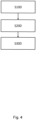
- FIG 4 shows a flow chart of the testing method according to the invention for detecting a defect of a transparent test specimen 5, in particular of an ophthalmic lens.
- the method comprises an image acquisition step S100, in which a plurality of stripe recordings 19 are captured by an image acquisition device 3, which are generated with the aid of an illumination device 2.
- the illumination device 2 for generating a stripe pattern 7, as already explained in detail with reference to Figure 1 and Figures 2a ) to 2e) comprises a plurality of light sources 8 which are linearly displaced in a first direction 9 by means of a first drive 12 in the image acquisition step S100.
- the acquisition duration of the image acquisition device 3 is set such that the light emitted from each of the linearly adjusted light sources 8 is captured as a light stripe 19.1 in each case.
- the illumination device 2 is, in a preferred embodiment, linearly adjusted by means of a second drive 13 in a second direction 10 which is substantially perpendicular to the first direction 9.
- the method according to the invention comprises a reconstruction step S200 in which an overall image is reconstructed from the stripe recordings 19, and a defect detection step S300 in which a defect is detected from the overall image.
- the detected defects are the further characterized especially by their nature and by their position with respect to a coordinate system, which might be defined by permanent engravings or other markings on the test specimen 5.
Landscapes
- Physics & Mathematics (AREA)
- Chemical & Material Sciences (AREA)
- Analytical Chemistry (AREA)
- General Physics & Mathematics (AREA)
- Geometry (AREA)
- Life Sciences & Earth Sciences (AREA)
- Health & Medical Sciences (AREA)
- Biochemistry (AREA)
- General Health & Medical Sciences (AREA)
- Immunology (AREA)
- Pathology (AREA)
- Investigating Materials By The Use Of Optical Means Adapted For Particular Applications (AREA)
- Eye Examination Apparatus (AREA)
Claims (14)
- Testvorrichtung (1) zum Detektieren von Defekten von transparenten Testmustern (5), insbesondere von Augengläsern, mit einer Beleuchtungsvorrichtung (2) zum Durchleuchten von zu untersuchenden Testmustern (5) und mit einer Bildererfassungsvorrichtung (3) zum Abbilden der durch die Beleuchtungsvorrichtung (2) durchleuchteten Testmuster (5), dadurch gekennzeichnet, dass die Beleuchtungsvorrichtung (2) eine Vielzahl von Lichtquellen (8) umfasst, die durch einen ersten Antrieb (12) in einer ersten Richtung (9) linear bewegbar sind, zum Erzeugen eines Streifenmusters (7), und dass, um das Streifenmuster (7) aufzunehmen, die Erfassungsdauer der Bildererfassungsvorrichtung (3) derart angepasst werden kann, dass das durch jede der Lichtquellen (8), durch den ersten Antrieb (12) in der ersten Richtung (9) linear bewegt, emittierte Licht als ein Lichtstreifen (19.1) detektiert wird.
- Testvorrichtung (1) nach Anspruch 1, dadurch gekennzeichnet, dass ein zweiter Antrieb (13) zur Neupositionierung der Lichtquellen (8) zwischen einzelnen Streifenaufzeichnungen in einer zweiten Richtung (10), im Wesentlichen senkrecht zu der ersten Richtung (9), vorgesehen ist.
- Testvorrichtung (1) nach Anspruch 2, dadurch gekennzeichnet, dass die erste Richtung (9) und die zweite Richtung (10) in jedem Fall im Wesentlichen senkrecht zu einem Beobachtungspfad (6) der Bildererfassungsvorrichtung (3) liegen.
- Testvorrichtung (1) nach einem der vorhergehenden Ansprüche, dadurch gekennzeichnet, dass die Lichtquellen (8) auf einem Lichtträger (11) angeordnet sind.
- Testvorrichtung (1) nach einem der vorhergehenden Ansprüche, dadurch gekennzeichnet, dass die Lichtquellen (8) unter einer äquidistanten Distanz (D) voneinander angeordnet sind.
- Testvorrichtung (1) nach einem der vorhergehenden Ansprüche, dadurch gekennzeichnet, dass die Distanz (D) zwischen benachbarten Lichtquellen (8) größer als 3 mm ist, bevorzugt größer als 5 mm ist und weiter bevorzugt kleiner als 12 mm ist, bevorzugt kleiner als 10 mm und besonders bevorzugt 7 mm ist.
- Testvorrichtung (1) nach einem der vorhergehenden Ansprüche, dadurch gekennzeichnet, dass die Anzahl von Lichtquellen (8) größer als 1 ist, bevorzugt größer als 8 ist und besonders bevorzugt größer als 12 ist und weiter bevorzugt kleiner als 50, bevorzugt kleiner als 30 und höchstbevorzugt 23 ist.
- Testvorrichtung (1) nach einem der vorhergehenden Ansprüche, dadurch gekennzeichnet, dass die Geschwindigkeit des ersten Antriebs (12) zum Bewegen der Lichtquellen (8) in der ersten Richtung (9) und/oder die Geschwindigkeit des zweiten Antriebs (13) zum Bewegen der Lichtquellen (8) in der zweiten Richtung (10) größer als 1000 mm/s ist, bevorzugt größer als 2000 mm/s ist, besonders bevorzugt größer als 2500 mm/s ist und stärker bevorzugt kleiner als 5000 mm/s ist, bevorzugt kleiner als 4000 mm/s ist, besonders bevorzugt kleiner als 3500 mm/s ist und höchstbevorzugt 3000 mm/s ist.
- Testvorrichtung (1) nach einem der vorhergehenden Ansprüche, dadurch gekennzeichnet, dass die Beschleunigung des ersten Antriebs (12) und/oder die Beschleunigung des zweiten Antriebs (13) größer als 10000 mm/s2 ist, bevorzugt größer als 15000 mm/s2 ist, besonders bevorzugt größer als 18000 mm/s2 ist und stärker bevorzugt kleiner als 30000 mm/s2 ist, bevorzugt kleiner als 25000 mm/s2 ist, besonders bevorzugt kleiner als 22000 mm/s2 ist und höchstbevorzugt 20000 mm/s2 ist.
- Testvorrichtung (1) nach einem der vorhergehenden Ansprüche, dadurch gekennzeichnet, dass die Bildererfassungsvorrichtung (3) eine Kamera (4) mit einem telezentrischen Objektiv (15) umfasst.
- Testverfahren zum Detektieren eines Defekts in einem transparenten Muster, insbesondere von einem Augenglas; umfassend:(a) einen Bilderfassungsschritt (S100), in dem eine Vielzahl von Streifenaufzeichnungen (19) durch eine Bildererfassungsvorrichtung (3) aufgenommen wird und mit der Hilfe einer Beleuchtungsvorrichtung (2) erzeugt wird;(b) einen Rekonstruktionsschritt (S200), in dem ein Gesamtbild aus den Streifenaufzeichnungen (19) rekonstruiert wird; und(c) einen Defektdetektionsschritt (S300), in dem ein möglicher Defekt anhand des Gesamtbilds detektiert wird;dadurch gekennzeichnet, dass
die Beleuchtungsvorrichtung (2) zum Erzeugen eines Streifenmusters (7) eine Vielzahl von Lichtquellen (8) umfasst, die in einer ersten Richtung (9) durch einen ersten Antrieb (12) in dem Bilderfassungsschritt (S100) linear bewegt werden, und dass, um das Streifenmuster (7) aufzunehmen, die Erfassungsdauer der Bildererfassungsvorrichtung (3) derart eingestellt wird, dass das durch die linear bewegten Lichtquellen (8) emittierte Licht jeweils als ein Lichtstreifen (19.1) detektiert wird. - Testverfahren nach Anspruch 11, dadurch gekennzeichnet, dass in dem Bilderfassungsschritt (S100), zum Verlagern des Streifenmusters (7) zwischen den einzelnen Streifenaufzeichnungen (19), die Lichtquellen (8) in einer zweiten Richtung (10) verlagert werden, die im Wesentlichen senkrecht zu der ersten Richtung (9) orientiert ist.
- Testverfahren nach Anspruch 11, dadurch gekennzeichnet, dass in dem Bilderfassungsschritt (S100), in jedem Fall verschiedene Lichtquellen (8) zum Erzeugen des Streifenmusters (7) in den einzelnen Streifenaufzeichnungen (19) verwendet werden.
- Testverfahren nach einem der Ansprüche 11 bis 13, dadurch gekennzeichnet, dass der Defektdetektionsschritt (S300) die Position der identifizierten Defekte aufnimmt.
Applications Claiming Priority (2)
| Application Number | Priority Date | Filing Date | Title |
|---|---|---|---|
| EP22157064.1A EP4231001A1 (de) | 2022-02-16 | 2022-02-16 | Testvorrichtung und testverfahren |
| PCT/EP2023/053464 WO2023156329A1 (en) | 2022-02-16 | 2023-02-13 | Testing device and testing method |
Publications (2)
| Publication Number | Publication Date |
|---|---|
| EP4288767A1 EP4288767A1 (de) | 2023-12-13 |
| EP4288767B1 true EP4288767B1 (de) | 2024-08-21 |
Family
ID=80682236
Family Applications (2)
| Application Number | Title | Priority Date | Filing Date |
|---|---|---|---|
| EP22157064.1A Withdrawn EP4231001A1 (de) | 2022-02-16 | 2022-02-16 | Testvorrichtung und testverfahren |
| EP23703616.5A Active EP4288767B1 (de) | 2022-02-16 | 2023-02-13 | Testvorrichtung und testverfahren |
Family Applications Before (1)
| Application Number | Title | Priority Date | Filing Date |
|---|---|---|---|
| EP22157064.1A Withdrawn EP4231001A1 (de) | 2022-02-16 | 2022-02-16 | Testvorrichtung und testverfahren |
Country Status (5)
| Country | Link |
|---|---|
| US (1) | US11885751B2 (de) |
| EP (2) | EP4231001A1 (de) |
| CN (1) | CN117677838B (de) |
| MX (1) | MX2024001198A (de) |
| WO (1) | WO2023156329A1 (de) |
Family Cites Families (25)
| Publication number | Priority date | Publication date | Assignee | Title |
|---|---|---|---|---|
| JPS5766345A (en) * | 1980-10-09 | 1982-04-22 | Hitachi Ltd | Inspection device for defect |
| DE3237511A1 (de) * | 1982-10-09 | 1984-04-12 | Fraunhofer-Gesellschaft zur Förderung der angewandten Forschung e.V., 8000 München | Verfahren zur pruefung von glaserzeugnissen |
| JPS60119404A (ja) * | 1983-12-01 | 1985-06-26 | Nippon Sheet Glass Co Ltd | 板ガラスの歪検査装置 |
| DE3620108A1 (de) * | 1986-06-14 | 1987-12-17 | Zeiss Carl Fa | Vorrichtung zum beleuchten von bauteilen aus transparentem material bei der fehlerpruefung |
| EP0344617B1 (de) * | 1988-05-30 | 1995-08-02 | Kabushiki Kaisha Kirin Techno System | Verfahren und Vorrichtung zur Prüfung der Seitenwände von Flaschen |
| DE4003699A1 (de) * | 1990-02-07 | 1991-08-22 | Wild Heerbrugg Ag | Verfahren und anordnung zur pruefung optischer komponenten oder systeme |
| NZ250042A (en) | 1992-12-21 | 1997-01-29 | Johnson & Johnson Vision Prod | Robotic inspection of ophthalmic lenses |
| JP3185599B2 (ja) * | 1995-04-17 | 2001-07-11 | 日産自動車株式会社 | 表面欠陥検査装置 |
| JP3736080B2 (ja) * | 1997-11-12 | 2006-01-18 | 旭硝子株式会社 | 透視歪の測定方法及び装置 |
| EP1248092B1 (de) | 2001-03-09 | 2010-09-15 | Novartis AG | Linsenprüfung |
| DE102004014532B3 (de) * | 2004-03-23 | 2005-03-03 | Koenig & Bauer Ag | Optisches System zur Erzeugung eines beleuchteten Gebildes |
| EP1605241A1 (de) | 2004-06-09 | 2005-12-14 | Automation & Robotics | Apparat zur optischen Kontrolle von transparenten oder reflektierenden Proben |
| JP4613086B2 (ja) * | 2005-03-25 | 2011-01-12 | 倉敷紡績株式会社 | 欠陥検査装置 |
| EP2126552A4 (de) * | 2007-02-16 | 2016-04-20 | 3M Innovative Properties Co | Verfahren und vorrichtung für die beleuchtung von material zur automatischen inspektion |
| EP2325625A1 (de) * | 2008-08-07 | 2011-05-25 | Kde Corporation | Inspektionssystem |
| DE102008064104B4 (de) * | 2008-12-19 | 2014-06-18 | Aimess Services Gmbh | Vorrichtung und Verfahren zum dreidimensionalen optischen Vermessen von stark reflektierenden oder durchsichtigen Objekten |
| US8976250B2 (en) * | 2012-05-01 | 2015-03-10 | Apple Inc. | Lens inspection system |
| CN102937425B (zh) * | 2012-10-18 | 2015-04-29 | 北京航空航天大学 | 一种基于高动态条纹投射器的强反射表面三维形貌测量系统 |
| FR3016699B1 (fr) * | 2014-01-22 | 2016-02-12 | Msc & Sgcc | Procede et dispositif pour la detection notamment de defauts refractants |
| JP6316068B2 (ja) * | 2014-03-31 | 2018-04-25 | 国立大学法人 東京大学 | 検査システムおよび検査方法 |
| CN105067639B (zh) * | 2015-07-20 | 2018-03-27 | 丹阳市精通眼镜技术创新服务中心有限公司 | 一种光栅调制的镜片疵病自动检测装置和方法 |
| EP3588048A1 (de) * | 2018-06-21 | 2020-01-01 | Essilor International (Compagnie Generale D'optique) | Verfahren zur detektion eines defekts in einem bereich einer optischen linse |
| GB2598283A (en) * | 2020-07-07 | 2022-03-02 | Eyoto Group Ltd | Method and apparatus for inspecting the surface of a transparent object |
| US11226293B1 (en) * | 2020-08-07 | 2022-01-18 | Seagate Technology Llc | Structured illumination optical inspection platform for transparent materials |
| CN113567342A (zh) * | 2021-08-20 | 2021-10-29 | 安徽顺鼎阿泰克科技有限公司 | 透明物缺陷检测方法及装置 |
-
2022
- 2022-02-16 EP EP22157064.1A patent/EP4231001A1/de not_active Withdrawn
-
2023
- 2023-02-13 CN CN202380010811.7A patent/CN117677838B/zh active Active
- 2023-02-13 WO PCT/EP2023/053464 patent/WO2023156329A1/en not_active Ceased
- 2023-02-13 EP EP23703616.5A patent/EP4288767B1/de active Active
- 2023-02-13 MX MX2024001198A patent/MX2024001198A/es unknown
- 2023-09-18 US US18/468,867 patent/US11885751B2/en active Active
Also Published As
| Publication number | Publication date |
|---|---|
| EP4288767A1 (de) | 2023-12-13 |
| US20240003829A1 (en) | 2024-01-04 |
| CN117677838B (zh) | 2025-07-08 |
| WO2023156329A1 (en) | 2023-08-24 |
| CN117677838A (zh) | 2024-03-08 |
| MX2024001198A (es) | 2024-02-12 |
| US11885751B2 (en) | 2024-01-30 |
| EP4231001A1 (de) | 2023-08-23 |
Similar Documents
| Publication | Publication Date | Title |
|---|---|---|
| DE112014004645B4 (de) | System und Verfahren zur Inspektion feuchter Kontaktlinsen | |
| US6201600B1 (en) | Method and apparatus for the automatic inspection of optically transmissive objects having a lens portion | |
| DE102012101377B4 (de) | Verfahren bei der Vorbereitung von Proben zum Mikroskopieren und Vorrichtung zum Überprüfen der Eindeckqualität von Proben | |
| KR101343277B1 (ko) | 표면 검사 장치 | |
| DE112007002949T5 (de) | Fehlerdetektionsvorrichtung, Fehlerdetektionsverfahren, Informationsverarbeitungsvorrichtung, Informationsverarbeitungsverfahren und Programm | |
| JP6430532B2 (ja) | ステント状物体を光学的に検査・分析する装置および方法 | |
| JP2019215321A (ja) | 溶液に浸された眼用レンズの屈折力および厚さを検査するためのシステムおよび方法 | |
| AT504940B1 (de) | Verfahren und apparat zur optischen messung der topografie einer probe | |
| DE102015110456B4 (de) | Purkinjemeter und Verfahren zur automatischen Auswertung | |
| DE10297337T5 (de) | Automatischer Inspektionsapparat und Verfahren zur Erkennung von Anomalien in einem 3-dimensionalen transluzenten Objekt | |
| DE102020109945A1 (de) | Verfahren und Inspektionseinrichtung zur optischen Inspektion einer Oberfläche | |
| DE102018206376B4 (de) | Prüfvorrichtung zum Prüfung von Intraokularlinsen | |
| JP2009506813A (ja) | ステントの自動検査装置及び自動検査方法 | |
| US12336760B2 (en) | Method for evaluating the stability of a tear film | |
| DE102008041135B4 (de) | Inspektionsvorrichtung- und Verfahren für die optische Untersuchung von Objektoberflächen, insbesondere einer Wafernotch | |
| EP4231001A1 (de) | Testvorrichtung und testverfahren | |
| DE102021131492A1 (de) | Vorrichtung zur Prüfung von Innenflächen sowie Beleuchtungseinrichtung dafür | |
| DE112009001936B4 (de) | Inspektionsvorrichtung- und Verfahren für die optische Untersuchung von Objektoberflächen, insbesondere von Waferkanten | |
| EP3388780B1 (de) | Verfahren und vorrichtung für das referenzieren der lage wenigstens eines punkts auf oder in einem transparenten gegenstand | |
| JP7306620B2 (ja) | 表面欠陥検査装置及び表面欠陥検査方法 | |
| US20170267965A1 (en) | Method and device for detecting inoculation and automated inoculation facility provided with such a detection device | |
| EP1563467A1 (de) | Verfahren zur fotografischen aufnahme eines zylinderförmigen, insbesondere plattenförmigen gegenstandes | |
| CN114199766B (zh) | 一种表面缺陷检测装置及检测方法 | |
| CN110907470A (zh) | 滤光片检测设备及滤光片检测方法 | |
| JP2007163315A (ja) | 透明材料中の欠陥の形状及び位置の計測方法 |
Legal Events
| Date | Code | Title | Description |
|---|---|---|---|
| STAA | Information on the status of an ep patent application or granted ep patent |
Free format text: STATUS: UNKNOWN |
|
| STAA | Information on the status of an ep patent application or granted ep patent |
Free format text: STATUS: THE INTERNATIONAL PUBLICATION HAS BEEN MADE |
|
| PUAI | Public reference made under article 153(3) epc to a published international application that has entered the european phase |
Free format text: ORIGINAL CODE: 0009012 |
|
| STAA | Information on the status of an ep patent application or granted ep patent |
Free format text: STATUS: REQUEST FOR EXAMINATION WAS MADE |
|
| 17P | Request for examination filed |
Effective date: 20230905 |
|
| AK | Designated contracting states |
Kind code of ref document: A1 Designated state(s): AL AT BE BG CH CY CZ DE DK EE ES FI FR GB GR HR HU IE IS IT LI LT LU LV MC ME MK MT NL NO PL PT RO RS SE SI SK SM TR |
|
| GRAP | Despatch of communication of intention to grant a patent |
Free format text: ORIGINAL CODE: EPIDOSNIGR1 |
|
| STAA | Information on the status of an ep patent application or granted ep patent |
Free format text: STATUS: GRANT OF PATENT IS INTENDED |
|
| DAV | Request for validation of the european patent (deleted) | ||
| DAX | Request for extension of the european patent (deleted) | ||
| INTG | Intention to grant announced |
Effective date: 20240315 |
|
| GRAS | Grant fee paid |
Free format text: ORIGINAL CODE: EPIDOSNIGR3 |
|
| GRAA | (expected) grant |
Free format text: ORIGINAL CODE: 0009210 |
|
| STAA | Information on the status of an ep patent application or granted ep patent |
Free format text: STATUS: THE PATENT HAS BEEN GRANTED |
|
| AK | Designated contracting states |
Kind code of ref document: B1 Designated state(s): AL AT BE BG CH CY CZ DE DK EE ES FI FR GB GR HR HU IE IS IT LI LT LU LV MC ME MK MT NL NO PL PT RO RS SE SI SK SM TR |
|
| RAP1 | Party data changed (applicant data changed or rights of an application transferred) |
Owner name: CARL ZEISS VISION INTERNATIONAL GMBH |
|
| REG | Reference to a national code |
Ref country code: GB Ref legal event code: FG4D |
|
| REG | Reference to a national code |
Ref country code: CH Ref legal event code: EP |
|
| REG | Reference to a national code |
Ref country code: IE Ref legal event code: FG4D |
|
| REG | Reference to a national code |
Ref country code: DE Ref legal event code: R096 Ref document number: 602023000430 Country of ref document: DE |
|
| REG | Reference to a national code |
Ref country code: LT Ref legal event code: MG9D |
|
| REG | Reference to a national code |
Ref country code: NL Ref legal event code: MP Effective date: 20240821 |
|
| PG25 | Lapsed in a contracting state [announced via postgrant information from national office to epo] |
Ref country code: NO Free format text: LAPSE BECAUSE OF FAILURE TO SUBMIT A TRANSLATION OF THE DESCRIPTION OR TO PAY THE FEE WITHIN THE PRESCRIBED TIME-LIMIT Effective date: 20241121 |
|
| REG | Reference to a national code |
Ref country code: AT Ref legal event code: MK05 Ref document number: 1715940 Country of ref document: AT Kind code of ref document: T Effective date: 20240821 |
|
| PG25 | Lapsed in a contracting state [announced via postgrant information from national office to epo] |
Ref country code: NL Free format text: LAPSE BECAUSE OF FAILURE TO SUBMIT A TRANSLATION OF THE DESCRIPTION OR TO PAY THE FEE WITHIN THE PRESCRIBED TIME-LIMIT Effective date: 20240821 Ref country code: GR Free format text: LAPSE BECAUSE OF FAILURE TO SUBMIT A TRANSLATION OF THE DESCRIPTION OR TO PAY THE FEE WITHIN THE PRESCRIBED TIME-LIMIT Effective date: 20241122 Ref country code: PT Free format text: LAPSE BECAUSE OF FAILURE TO SUBMIT A TRANSLATION OF THE DESCRIPTION OR TO PAY THE FEE WITHIN THE PRESCRIBED TIME-LIMIT Effective date: 20241223 Ref country code: FI Free format text: LAPSE BECAUSE OF FAILURE TO SUBMIT A TRANSLATION OF THE DESCRIPTION OR TO PAY THE FEE WITHIN THE PRESCRIBED TIME-LIMIT Effective date: 20240821 Ref country code: PL Free format text: LAPSE BECAUSE OF FAILURE TO SUBMIT A TRANSLATION OF THE DESCRIPTION OR TO PAY THE FEE WITHIN THE PRESCRIBED TIME-LIMIT Effective date: 20240821 |
|
| PG25 | Lapsed in a contracting state [announced via postgrant information from national office to epo] |
Ref country code: BG Free format text: LAPSE BECAUSE OF FAILURE TO SUBMIT A TRANSLATION OF THE DESCRIPTION OR TO PAY THE FEE WITHIN THE PRESCRIBED TIME-LIMIT Effective date: 20240821 |
|
| PG25 | Lapsed in a contracting state [announced via postgrant information from national office to epo] |
Ref country code: LV Free format text: LAPSE BECAUSE OF FAILURE TO SUBMIT A TRANSLATION OF THE DESCRIPTION OR TO PAY THE FEE WITHIN THE PRESCRIBED TIME-LIMIT Effective date: 20240821 |
|
| PG25 | Lapsed in a contracting state [announced via postgrant information from national office to epo] |
Ref country code: AT Free format text: LAPSE BECAUSE OF FAILURE TO SUBMIT A TRANSLATION OF THE DESCRIPTION OR TO PAY THE FEE WITHIN THE PRESCRIBED TIME-LIMIT Effective date: 20240821 Ref country code: IS Free format text: LAPSE BECAUSE OF FAILURE TO SUBMIT A TRANSLATION OF THE DESCRIPTION OR TO PAY THE FEE WITHIN THE PRESCRIBED TIME-LIMIT Effective date: 20241221 |
|
| PG25 | Lapsed in a contracting state [announced via postgrant information from national office to epo] |
Ref country code: HR Free format text: LAPSE BECAUSE OF FAILURE TO SUBMIT A TRANSLATION OF THE DESCRIPTION OR TO PAY THE FEE WITHIN THE PRESCRIBED TIME-LIMIT Effective date: 20240821 |
|
| PG25 | Lapsed in a contracting state [announced via postgrant information from national office to epo] |
Ref country code: RS Free format text: LAPSE BECAUSE OF FAILURE TO SUBMIT A TRANSLATION OF THE DESCRIPTION OR TO PAY THE FEE WITHIN THE PRESCRIBED TIME-LIMIT Effective date: 20241121 Ref country code: ES Free format text: LAPSE BECAUSE OF FAILURE TO SUBMIT A TRANSLATION OF THE DESCRIPTION OR TO PAY THE FEE WITHIN THE PRESCRIBED TIME-LIMIT Effective date: 20240821 |
|
| PG25 | Lapsed in a contracting state [announced via postgrant information from national office to epo] |
Ref country code: RS Free format text: LAPSE BECAUSE OF FAILURE TO SUBMIT A TRANSLATION OF THE DESCRIPTION OR TO PAY THE FEE WITHIN THE PRESCRIBED TIME-LIMIT Effective date: 20241121 Ref country code: PT Free format text: LAPSE BECAUSE OF FAILURE TO SUBMIT A TRANSLATION OF THE DESCRIPTION OR TO PAY THE FEE WITHIN THE PRESCRIBED TIME-LIMIT Effective date: 20241223 Ref country code: PL Free format text: LAPSE BECAUSE OF FAILURE TO SUBMIT A TRANSLATION OF THE DESCRIPTION OR TO PAY THE FEE WITHIN THE PRESCRIBED TIME-LIMIT Effective date: 20240821 Ref country code: NO Free format text: LAPSE BECAUSE OF FAILURE TO SUBMIT A TRANSLATION OF THE DESCRIPTION OR TO PAY THE FEE WITHIN THE PRESCRIBED TIME-LIMIT Effective date: 20241121 Ref country code: NL Free format text: LAPSE BECAUSE OF FAILURE TO SUBMIT A TRANSLATION OF THE DESCRIPTION OR TO PAY THE FEE WITHIN THE PRESCRIBED TIME-LIMIT Effective date: 20240821 Ref country code: LV Free format text: LAPSE BECAUSE OF FAILURE TO SUBMIT A TRANSLATION OF THE DESCRIPTION OR TO PAY THE FEE WITHIN THE PRESCRIBED TIME-LIMIT Effective date: 20240821 Ref country code: IS Free format text: LAPSE BECAUSE OF FAILURE TO SUBMIT A TRANSLATION OF THE DESCRIPTION OR TO PAY THE FEE WITHIN THE PRESCRIBED TIME-LIMIT Effective date: 20241221 Ref country code: HR Free format text: LAPSE BECAUSE OF FAILURE TO SUBMIT A TRANSLATION OF THE DESCRIPTION OR TO PAY THE FEE WITHIN THE PRESCRIBED TIME-LIMIT Effective date: 20240821 Ref country code: GR Free format text: LAPSE BECAUSE OF FAILURE TO SUBMIT A TRANSLATION OF THE DESCRIPTION OR TO PAY THE FEE WITHIN THE PRESCRIBED TIME-LIMIT Effective date: 20241122 Ref country code: FI Free format text: LAPSE BECAUSE OF FAILURE TO SUBMIT A TRANSLATION OF THE DESCRIPTION OR TO PAY THE FEE WITHIN THE PRESCRIBED TIME-LIMIT Effective date: 20240821 Ref country code: ES Free format text: LAPSE BECAUSE OF FAILURE TO SUBMIT A TRANSLATION OF THE DESCRIPTION OR TO PAY THE FEE WITHIN THE PRESCRIBED TIME-LIMIT Effective date: 20240821 Ref country code: BG Free format text: LAPSE BECAUSE OF FAILURE TO SUBMIT A TRANSLATION OF THE DESCRIPTION OR TO PAY THE FEE WITHIN THE PRESCRIBED TIME-LIMIT Effective date: 20240821 Ref country code: AT Free format text: LAPSE BECAUSE OF FAILURE TO SUBMIT A TRANSLATION OF THE DESCRIPTION OR TO PAY THE FEE WITHIN THE PRESCRIBED TIME-LIMIT Effective date: 20240821 |
|
| PG25 | Lapsed in a contracting state [announced via postgrant information from national office to epo] |
Ref country code: SM Free format text: LAPSE BECAUSE OF FAILURE TO SUBMIT A TRANSLATION OF THE DESCRIPTION OR TO PAY THE FEE WITHIN THE PRESCRIBED TIME-LIMIT Effective date: 20240821 Ref country code: RO Free format text: LAPSE BECAUSE OF FAILURE TO SUBMIT A TRANSLATION OF THE DESCRIPTION OR TO PAY THE FEE WITHIN THE PRESCRIBED TIME-LIMIT Effective date: 20240821 Ref country code: DK Free format text: LAPSE BECAUSE OF FAILURE TO SUBMIT A TRANSLATION OF THE DESCRIPTION OR TO PAY THE FEE WITHIN THE PRESCRIBED TIME-LIMIT Effective date: 20240821 |
|
| PG25 | Lapsed in a contracting state [announced via postgrant information from national office to epo] |
Ref country code: EE Free format text: LAPSE BECAUSE OF FAILURE TO SUBMIT A TRANSLATION OF THE DESCRIPTION OR TO PAY THE FEE WITHIN THE PRESCRIBED TIME-LIMIT Effective date: 20240821 |
|
| PG25 | Lapsed in a contracting state [announced via postgrant information from national office to epo] |
Ref country code: CZ Free format text: LAPSE BECAUSE OF FAILURE TO SUBMIT A TRANSLATION OF THE DESCRIPTION OR TO PAY THE FEE WITHIN THE PRESCRIBED TIME-LIMIT Effective date: 20240821 |
|
| PG25 | Lapsed in a contracting state [announced via postgrant information from national office to epo] |
Ref country code: SK Free format text: LAPSE BECAUSE OF FAILURE TO SUBMIT A TRANSLATION OF THE DESCRIPTION OR TO PAY THE FEE WITHIN THE PRESCRIBED TIME-LIMIT Effective date: 20240821 Ref country code: IT Free format text: LAPSE BECAUSE OF FAILURE TO SUBMIT A TRANSLATION OF THE DESCRIPTION OR TO PAY THE FEE WITHIN THE PRESCRIBED TIME-LIMIT Effective date: 20240821 |
|
| REG | Reference to a national code |
Ref country code: DE Ref legal event code: R097 Ref document number: 602023000430 Country of ref document: DE |
|
| PLBE | No opposition filed within time limit |
Free format text: ORIGINAL CODE: 0009261 |
|
| STAA | Information on the status of an ep patent application or granted ep patent |
Free format text: STATUS: NO OPPOSITION FILED WITHIN TIME LIMIT |
|
| 26N | No opposition filed |
Effective date: 20250522 |
|
| PG25 | Lapsed in a contracting state [announced via postgrant information from national office to epo] |
Ref country code: SE Free format text: LAPSE BECAUSE OF FAILURE TO SUBMIT A TRANSLATION OF THE DESCRIPTION OR TO PAY THE FEE WITHIN THE PRESCRIBED TIME-LIMIT Effective date: 20240821 |
|
| PG25 | Lapsed in a contracting state [announced via postgrant information from national office to epo] |
Ref country code: MC Free format text: LAPSE BECAUSE OF FAILURE TO SUBMIT A TRANSLATION OF THE DESCRIPTION OR TO PAY THE FEE WITHIN THE PRESCRIBED TIME-LIMIT Effective date: 20240821 |
|
| PG25 | Lapsed in a contracting state [announced via postgrant information from national office to epo] |
Ref country code: LU Free format text: LAPSE BECAUSE OF NON-PAYMENT OF DUE FEES Effective date: 20250213 |
|
| REG | Reference to a national code |
Ref country code: BE Ref legal event code: MM Effective date: 20250228 |
|
| PG25 | Lapsed in a contracting state [announced via postgrant information from national office to epo] |
Ref country code: FR Free format text: LAPSE BECAUSE OF NON-PAYMENT OF DUE FEES Effective date: 20250228 |
|
| PG25 | Lapsed in a contracting state [announced via postgrant information from national office to epo] |
Ref country code: BE Free format text: LAPSE BECAUSE OF NON-PAYMENT OF DUE FEES Effective date: 20250228 |
|
| PG25 | Lapsed in a contracting state [announced via postgrant information from national office to epo] |
Ref country code: IE Free format text: LAPSE BECAUSE OF NON-PAYMENT OF DUE FEES Effective date: 20250213 |
|
| PGFP | Annual fee paid to national office [announced via postgrant information from national office to epo] |
Ref country code: DE Payment date: 20260218 Year of fee payment: 4 |