EP4287584A1 - Method and apparatus for transmitting call audio data - Google Patents
Method and apparatus for transmitting call audio data Download PDFInfo
- Publication number
- EP4287584A1 EP4287584A1 EP22918383.5A EP22918383A EP4287584A1 EP 4287584 A1 EP4287584 A1 EP 4287584A1 EP 22918383 A EP22918383 A EP 22918383A EP 4287584 A1 EP4287584 A1 EP 4287584A1
- Authority
- EP
- European Patent Office
- Prior art keywords
- call
- audio
- pcm
- electronic device
- pcm device
- Prior art date
- Legal status (The legal status is an assumption and is not a legal conclusion. Google has not performed a legal analysis and makes no representation as to the accuracy of the status listed.)
- Pending
Links
- 238000000034 method Methods 0.000 title claims abstract description 63
- 230000004044 response Effects 0.000 claims abstract description 22
- 238000004891 communication Methods 0.000 claims description 38
- 230000006854 communication Effects 0.000 claims description 38
- 238000004590 computer program Methods 0.000 claims description 11
- 230000005540 biological transmission Effects 0.000 abstract description 15
- 230000005236 sound signal Effects 0.000 abstract description 7
- 230000006870 function Effects 0.000 description 48
- 101000581507 Homo sapiens Methyl-CpG-binding domain protein 1 Proteins 0.000 description 27
- 101001134861 Homo sapiens Pericentriolar material 1 protein Proteins 0.000 description 27
- 102100027383 Methyl-CpG-binding domain protein 1 Human genes 0.000 description 27
- 101150033318 pcm2 gene Proteins 0.000 description 26
- 101150103044 pcm3 gene Proteins 0.000 description 25
- 238000010586 diagram Methods 0.000 description 11
- 230000008569 process Effects 0.000 description 10
- 238000012545 processing Methods 0.000 description 10
- 238000010079 rubber tapping Methods 0.000 description 10
- 230000010267 cellular communication Effects 0.000 description 9
- 238000010295 mobile communication Methods 0.000 description 9
- 238000012544 monitoring process Methods 0.000 description 5
- 230000001413 cellular effect Effects 0.000 description 3
- 230000008878 coupling Effects 0.000 description 3
- 238000010168 coupling process Methods 0.000 description 3
- 238000005859 coupling reaction Methods 0.000 description 3
- 238000012546 transfer Methods 0.000 description 3
- 238000013528 artificial neural network Methods 0.000 description 2
- 230000009286 beneficial effect Effects 0.000 description 2
- 238000011161 development Methods 0.000 description 2
- -1 ... Proteins 0.000 description 1
- 230000001133 acceleration Effects 0.000 description 1
- 230000003321 amplification Effects 0.000 description 1
- 230000007175 bidirectional communication Effects 0.000 description 1
- 210000000988 bone and bone Anatomy 0.000 description 1
- 230000000295 complement effect Effects 0.000 description 1
- 238000013461 design Methods 0.000 description 1
- 230000000694 effects Effects 0.000 description 1
- 238000005516 engineering process Methods 0.000 description 1
- 238000001914 filtration Methods 0.000 description 1
- 230000006872 improvement Effects 0.000 description 1
- 238000003199 nucleic acid amplification method Methods 0.000 description 1
- 230000005855 radiation Effects 0.000 description 1
- 230000001960 triggered effect Effects 0.000 description 1
Images


Classifications
-
- H—ELECTRICITY
- H04—ELECTRIC COMMUNICATION TECHNIQUE
- H04L—TRANSMISSION OF DIGITAL INFORMATION, e.g. TELEGRAPHIC COMMUNICATION
- H04L65/00—Network arrangements, protocols or services for supporting real-time applications in data packet communication
- H04L65/1066—Session management
- H04L65/1083—In-session procedures
- H04L65/1094—Inter-user-equipment sessions transfer or sharing
-
- H—ELECTRICITY
- H04—ELECTRIC COMMUNICATION TECHNIQUE
- H04M—TELEPHONIC COMMUNICATION
- H04M1/00—Substation equipment, e.g. for use by subscribers
- H04M1/253—Telephone sets using digital voice transmission
- H04M1/2535—Telephone sets using digital voice transmission adapted for voice communication over an Internet Protocol [IP] network
-
- H—ELECTRICITY
- H04—ELECTRIC COMMUNICATION TECHNIQUE
- H04M—TELEPHONIC COMMUNICATION
- H04M1/00—Substation equipment, e.g. for use by subscribers
- H04M1/64—Automatic arrangements for answering calls; Automatic arrangements for recording messages for absent subscribers; Arrangements for recording conversations
- H04M1/65—Recording arrangements for recording a message from the calling party
- H04M1/656—Recording arrangements for recording a message from the calling party for recording conversations
-
- H—ELECTRICITY
- H04—ELECTRIC COMMUNICATION TECHNIQUE
- H04M—TELEPHONIC COMMUNICATION
- H04M1/00—Substation equipment, e.g. for use by subscribers
- H04M1/72—Mobile telephones; Cordless telephones, i.e. devices for establishing wireless links to base stations without route selection
- H04M1/724—User interfaces specially adapted for cordless or mobile telephones
- H04M1/72403—User interfaces specially adapted for cordless or mobile telephones with means for local support of applications that increase the functionality
- H04M1/72409—User interfaces specially adapted for cordless or mobile telephones with means for local support of applications that increase the functionality by interfacing with external accessories
- H04M1/72412—User interfaces specially adapted for cordless or mobile telephones with means for local support of applications that increase the functionality by interfacing with external accessories using two-way short-range wireless interfaces
-
- H—ELECTRICITY
- H04—ELECTRIC COMMUNICATION TECHNIQUE
- H04W—WIRELESS COMMUNICATION NETWORKS
- H04W72/00—Local resource management
- H04W72/12—Wireless traffic scheduling
- H04W72/1263—Mapping of traffic onto schedule, e.g. scheduled allocation or multiplexing of flows
- H04W72/1268—Mapping of traffic onto schedule, e.g. scheduled allocation or multiplexing of flows of uplink data flows
-
- H—ELECTRICITY
- H04—ELECTRIC COMMUNICATION TECHNIQUE
- H04W—WIRELESS COMMUNICATION NETWORKS
- H04W72/00—Local resource management
- H04W72/12—Wireless traffic scheduling
- H04W72/1263—Mapping of traffic onto schedule, e.g. scheduled allocation or multiplexing of flows
- H04W72/1273—Mapping of traffic onto schedule, e.g. scheduled allocation or multiplexing of flows of downlink data flows
-
- H—ELECTRICITY
- H04—ELECTRIC COMMUNICATION TECHNIQUE
- H04W—WIRELESS COMMUNICATION NETWORKS
- H04W88/00—Devices specially adapted for wireless communication networks, e.g. terminals, base stations or access point devices
- H04W88/02—Terminal devices
- H04W88/04—Terminal devices adapted for relaying to or from another terminal or user
-
- Y—GENERAL TAGGING OF NEW TECHNOLOGICAL DEVELOPMENTS; GENERAL TAGGING OF CROSS-SECTIONAL TECHNOLOGIES SPANNING OVER SEVERAL SECTIONS OF THE IPC; TECHNICAL SUBJECTS COVERED BY FORMER USPC CROSS-REFERENCE ART COLLECTIONS [XRACs] AND DIGESTS
- Y02—TECHNOLOGIES OR APPLICATIONS FOR MITIGATION OR ADAPTATION AGAINST CLIMATE CHANGE
- Y02D—CLIMATE CHANGE MITIGATION TECHNOLOGIES IN INFORMATION AND COMMUNICATION TECHNOLOGIES [ICT], I.E. INFORMATION AND COMMUNICATION TECHNOLOGIES AIMING AT THE REDUCTION OF THEIR OWN ENERGY USE
- Y02D30/00—Reducing energy consumption in communication networks
- Y02D30/70—Reducing energy consumption in communication networks in wireless communication networks
Definitions
- This application relates to the field of communication technologies, and in particular, to a method for transmitting call audio data and an apparatus.
- Call functions based on a cellular communication network is a common function of mobile phones, but electronic devices not supporting a cellular network do not have this function.
- a second electronic device in collaboration with a first electronic device such as a mobile phone that supports cellular communication can implement the call function based on the cellular communication network.
- Embodiments of this application provide a method for transmitting call audio data and an apparatus, to implement call audio data transmission between different electronic devices.
- this application provides a method for transmitting call audio data.
- the method is applied to a first electronic device.
- the first electronic device includes a first PCM device, a second PCM device and a third PCM device.
- the first PCM device, the second PCM device and the third PCM device are configured to cache PCM audio data.
- the method includes: establishing a call with a peer electronic device in response to a call operation, where the first electronic device and the second electronic device are in a multi-screen collaboration mode, receiving call audio downlink data transmitted by the peer electronic device, storing the call audio downlink data transmitted in the first PCM device, transmitting the call audio downlink data in the first PCM device to the second electronic device, receiving call audio uplink data transmitted by the second electronic device, storing the call audio uplink data transmitted by the second electronic device in the second PCM device, transmitting the call audio uplink data in the second PCM device to the peer electronic device, and storing the call audio uplink data and the call audio downlink data in the third PCM device in response to an incall record operation.
- the first PCM device, the second PCM device and the third PCM device are different. It can be learned that, different PCM devices are used to respectively implement transmission and recording of the call audio uplink data and call audio downlink data, so that a possibility of cache data conflicts in a PCM device caused by multiplexing a PCM device can be reduced. Furthermore, a problem of increased power consumption caused by solving conflicts for an electronic device can further be avoided.
- the establishing a call with a peer electronic device includes establishing a call with the peer electronic device through a modulator-demodulator Modem.
- the storing the call audio downlink data in the first PCM device includes opening the first PCM device and a collaboration call downlink path by opening a first PCM device file.
- the collaboration call downlink path is configured to connect the first PCM device and the Modem. Opening the first PCM device through the first PCM device file can simplify operations, correspond to operation logics of a software system and have good compatibility.
- the collaboration call downlink path is configured to connect the first PCM device to the Modem. Therefore, opening the path can implement a function of transmitting the call audio downlink data from the Modem to the first PCM device through the collaboration call downlink path, and further to the second electronic device, to further reduce complexity of implementation.
- the transmitting the call audio downlink data to the second electronic device includes reading the call audio downlink data from the first PCM device by performing a read operation on the first PCM device file; and transmitting the call audio downlink data to the second electronic device.
- Performing the operation on the first PCM device to read the data in the first PCM device can simplify operations, and have good compatibility.
- the establishing a call with a peer electronic device includes establishing a call with the peer electronic device through the Modem.
- the storing the call audio uplink data in the second PCM device and transmitting the call audio uplink data in the second PCM device to the peer electronic device includes opening the second PCM device and a collaboration call uplink path by opening a second PCM device file, receiving the call audio uplink data transmitted by the second electronic device; and storing the call audio uplink data in the second PCM device by performing a write operation on the second PCM device file. Opening the second PCM device file to open the second PCM device and the collaboration call uplink path. Performing the operation on the second PCM device file to write the call audio uplink data into the second PCM device. Because the collaboration call uplink path is configured to connect the second PCM device and the Modem, the call audio uplink data is transmitted from the second PCM device to the Modem through the collaboration call uplink path, and further to a peer mobile phone, to further reduce complexity to implement.
- the establishing a call with a peer electronic device includes: establishing the call with the peer electronic device through the Modem.
- the storing the call audio uplink data and the call audio downlink data in the third PCM device includes: opening the third PCM device and an incall record Incall Record path by opening a third PCM device file.
- the incall record Incall Record path is configured to connect the third PCM device and the Modem, to further reduce complexity to implement.
- the method further includes: obtaining the call audio uplink data and the call audio downlink data from the third PCM device by reading the third PCM device file, and recording the call audio downlink data and the call audio uplink data. It can be learned that the third PCM device can provide the call audio uplink data and the call audio downlink data for a subsequent recording, to avoid operations including audio mixing, to reduce power consumption.
- the method further includes: closing, in response to an incall record end operation or a call end operation, the third PCM device by closing the third PCM device file. Closing the PCM device through the PCM device file can simplify operations, and have good compatibility.
- the method further includes: in response to the call end operation, closing the first PCM device by closing the first PCM device file, and closing the second PCM device by closing the second PCM device file. Closing the PCM device through the PCM device file can simplify operations, and have good compatibility.
- the method before the storing the call audio downlink data transmitted by the peer electronic device in the first PCM device, and the storing the call audio uplink data transmitted by the second electronic device in the second PCM device, the method further includes: determining the PCM device corresponding to the downlink call scenario in the multi-screen collaboration mode as the first PCM device, and the PCM device corresponding to the uplink call scenario in the multi-screen collaboration mode as the second PCM device, by querying a correspondence between a USECASE and a PCM device. It can be learned that the method can pre-configure a correspondence and modify the correspondence through the configuration, to modify a PCM device used in a scenario, to improve flexibility of the audio data transmission method.
- the method before the establishing a call with a peer electronic device in response to a call operation, the method further includes displaying a collaboration window.
- the collaboration window includes a dialing interface or an incoming call interface displayed on the second electronic device.
- the establishing a call with a peer electronic device in response to a call operation includes establishing a call with the peer electronic device in response to the call operation on the dialing interface or the incoming call interface. Implementing a call function based on the collaboration window operation can improve user experience.
- the method before the displaying a collaboration window, the method further includes starting the multi-screen collaboration mode with the second electronic device through near field communication NFC, Bluetooth, or in a wired manner. Diversity in implementations of the multi-screen collaboration mode can further improve user experience.
- this application provides an electronic device, including a memory and at least one processor.
- the memory is configured to store a program.
- the processor is configured to execute the program, to implement the method for transmitting call audio data according to the first aspect of this application.
- this application provides a computer storage medium configured to store a computer program.
- the computer program when executed is configured to implement the method for transmitting call audio data according to the first aspect of this application.
- this application provides a computer program product. When operated on the computer, the computer program product is configured to implement the method for transmitting call audio data according to the first aspect of this application.
- a and/or B may represent the following three cases: Only A exists, both A and B exist, and only B exists, where A and B each may be in a singular or plural form.
- the character "/" in this specification generally indicates an "or" relationship between the associated objects.
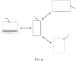
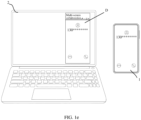
- FIG. 1a shows an example of a scenario of multi-device collaboration.
- a mobile phone 1 and a notebook computer 2, a personal digital assistant (Personal Digital Assistant, PDA) 3 and a large screen 4 can respectively enter a multi-screen collaboration mode.
- PDA Personal Digital Assistant
- the notebook computer 2 the PAD 3 and the large screen 4 that have no cellular communication capability, through a cellular communication capability of the mobile phone 1, can perform cellular network-based communication, including but not limited to making a call, answering a call, and making a cellular network-based video call.
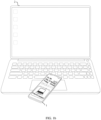
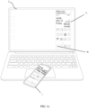
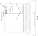
- FIG. 1b in a case that the mobile phone 1 enables a near field communication (Near Field Communication, NFC) function, after approaching a touchpad of the notebook computer 2 that enables the NFC function, the mobile phone 1 displays a connection interface with the notebook computer 2. As shown in FIG. 1c , after a "connect" control on the connection interface is tapped, the mobile phone 1 and the notebook computer 2 enters the multi-screen collaboration mode.
- NFC Near Field Communication
- a collaboration window A of the mobile phone 1 is displayed on the notebook computer 2, and displayed content of the collaboration window A and content currently displayed on the mobile phone 1 are the same.
- the mobile phone 1 currently displays a desktop, and a collaboration window A of the notebook computer 2 displays a same desktop.
- an operation that is the same as the operation on the mobile phone 1 can be performed by clicking a mouse or by tapping.
- a cursor of the mouse is placed in the collaboration window A of the notebook computer 2, and two fingers slide on the touchpad of the notebook computer 2, so that a plurality of desktops of the mobile phone can be switched in the collaboration window A.
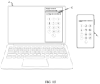
- an icon B of a telephone application displayed in the collaboration window A is tapped or is clicked by using a mouse to enter a collaboration dialing interface C.
- a call can be made on the collaboration dialing interface C by tapping or by clicking the mouse.
- a collaboration incoming call interface D is displayed in a collaboration desktop A of the notebook computer 2, and a call can be answered on the collaboration incoming call interface D by tapping or by clicking a mouse.
- the notebook computer 2 makes or answers a call through a cellular communication network of the mobile phone 1, after the call is connected, the mobile phone 1 and the notebook computer 2 need to exchange call audio data.
- Embodiments of this application provide a method for transmitting call audio data, to resolve a problem of audio data transmission between devices in the multi-screen collaboration mode in a multi-screen collaboration scenario.
- Embodiments of this application are applied to an electronic device with a cellular communication function.
- the electronic device may be a mobile phone (as shown in FIG. 2 ), a tablet computer, a desktop computer, a laptop computer, a notebook computer, an ultra-mobile personal computer (Ultra-mobile Personal Computer, UMPC), a handheld computer, a netbook, a personal digital assistant (Personal Digital Assistant, PDA), a wearable electronic device, a smart watch, or the like.
- the mobile phone shown in FIG. 2 includes a processor 110, an external memory interface 120, an internal memory 121, a universal serial bus (universal serial bus, USB) interface 130, a charging management module 140, a power management module 141, a battery 142, an antenna 1, an antenna 2, a mobile communication module 150, a wireless communication module 160, and an audio module 170, a speaker 170A, a phone receiver 170B, a microphone 170C, a headset jack 170D, a sensor module 180, a key 190, a motor 191, an indicator 192, a camera 193, a display screen 194, a subscriber identity module (subscriber identity module, SIM) card interface 195, and the like.
- a processor 110 an external memory interface 120, an internal memory 121, a universal serial bus (universal serial bus, USB) interface 130, a charging management module 140, a power management module 141, a battery 142, an antenna 1, an antenna 2, a mobile communication module 150, a wireless communication module 160, and
- the sensor module 180 may include a pressure sensor 180A, a gyroscope sensor 180B, a barometric pressure sensor 180C, a magnetic sensor 180D, an acceleration sensor 180E, a range sensor 180F, a proximity light sensor 180G, a fingerprint sensor 180H, a temperature sensor 180J, a touch sensor 180K, an ambient light sensor 180L, a bone conduction sensor 180M, and the like. It may be understood that the schematic structure in this embodiment constitutes no specific limitation on the electronic device. In some other embodiments, the electronic device may include more or fewer components than those shown in the figure, or some components may be combined, or some components may be split, or components are arranged in different manners. The components in the portrait may be implemented by hardware, software, or a combination of software and hardware.
- the processor 110 may include one or more processing units.
- the processor 110 may include an application processor (application processor, AP), a modem processor, a graphics processing unit (graphics processing unit, GPU), an image signal processor (image signal processor, ISP), a controller, a video codec, a digital signal processor (digital signal processor, DSP), an audio signal processor (audio signal processor, ADSP), a baseband processor, and/or a neural-network processing unit (neural-network processing unit, NPU).
- Different processing units may be separate devices, or may be integrated into one or more processors.
- a memory may also be disposed in the processor 110, configured to store instructions and data.
- the memory in processor 110 is a cache memory.
- the memory may store instructions or data recently used or cyclically used by the processor 110. If the processor 110 needs to use the instruction or the data again, the processor may directly invoke the instruction or the data from the memory. Repeated access is avoided, and waiting time of the processor 110 is reduced, thereby improving system efficiency.
- the processor 110 may include one or more interfaces.
- the interface may include an inter-integrated circuit (inter-integrated circuit, I2C) interface, an inter-integrated circuit sound (inter-integrated circuit sound, I2S) interface, a pulse code modulation (pulse code modulation, PCM) interface, a universal asynchronous receiver/transmitter (universal asynchronous receiver/transmitter, UART) interface, a mobile industry processor interface (mobile industry processor interface, MIPI), a general-purpose input/output (general-purpose input/output, GPIO) interface, a subscriber identity module (subscriber identity module, SIM) interface, and/or a universal serial bus (universal serial bus, USB) interface, and the like.
- I2C inter-integrated circuit
- I2S inter-integrated circuit sound
- PCM pulse code modulation
- PCM pulse code modulation
- UART universal asynchronous receiver/transmitter
- MIPI mobile industry processor interface
- GPIO general-purpose input/output
- the I2S interface may be configured to perform audio communication.
- the processor 110 may include a plurality of I2S buses.
- the processor 110 may be coupled to the audio module 170 through the I2S bus to implement communication between the processor 110 and the audio module 170.
- the audio module 170 may transmit an audio signal to the wireless communication module 160 through the I2S interface, to perform a function of answering a call through a Bluetooth headset.
- the PCM interface may also be configured to perform audio communication, to sample, quantize, and encode an analog signal.
- the audio module 170 may be coupled to the wireless communication module 160 through a PCM bus interface.
- the audio module 170 may also transfer an audio signal to the wireless communication module 160 through the PCM interface, to perform the function of answering a call through the Bluetooth headset. Both the I2S interface and the PCM interface may be configured to perform audio communication.
- the UART interface is a universal serial data bus and is configured to perform asynchronous communication.
- the bus may be a bidirectional communication bus.
- the bus converts data to be transmitted between serial communication and parallel communication.
- the UART interface is usually configured to connect the processor 110 to the wireless communication module 160.
- the processor 110 communicates with a Bluetooth module in the wireless communication module 160 through the UART interface, to perform a Bluetooth function.
- the audio module 170 may transfer an audio signal to the wireless communication module 160 through the UART interface, to perform a function of playing music through the Bluetooth headset.
- an interface connection relationship between the modules illustrated in this embodiment is merely an example for description, and does not constitute a limitation on a structure of the electronic device.
- the electronic device may alternatively use an interface connection manner different from that in the foregoing embodiment, or use a combination of a plurality of interface connection manners.
- a wireless communication function of the electronic device may be implemented by using the antenna 1, the antenna 2, the mobile communication module 150, the wireless communication module 160, the modem processor, the baseband processor, and the like.
- the antenna 1 and the antenna 2 are configured to transmit and receive an electromagnetic wave signal.
- Each antenna in the electronic device may be configured to cover one or more communication frequency bands. Different antennas may further be multiplexed to improve utilization of the antennas.
- an antenna 1 may be multiplexed as a diversity antenna of a wireless local area network.
- the antennas may be used with a tuning switch.
- the mobile communication module 150 can provide a wireless communication solution including such as 2G/3G/4G/5G applied on the electronic device.
- the mobile communication module 150 may include at least one filter, a switch, a power amplifier, a low noise amplifier (low noise amplifier, LNA), and the like.
- the mobile communication module 150 may receive an electromagnetic wave by using the antenna 1, perform processing such as filtering and amplification on the received electromagnetic wave, and send the electromagnetic wave to the modem processor for demodulation.
- the mobile communication module 150 may further amplify a signal modulated by the modem processor, and convert the signal into an electromagnetic wave by using the antenna 1 for radiation.
- at least some functional modules of the mobile communication module 150 may be disposed in the processor 110.
- at least some of the functional modules of the mobile communication module 150 may be disposed in a same device as at least some of modules of the processor 110.
- the modulation and demodulation processor may include a modulator and a demodulator.
- the modulator is configured to modulate a low frequency baseband signal to be sent into a medium and high frequency signal.
- the demodulator is configured to demodulate the received electromagnetic wave signal into a low-frequency baseband signal. Then the demodulator transfers the low-frequency baseband signal obtained through demodulation to the baseband processor for processing.
- the low-frequency baseband signal is processed by the baseband processor and then transferred to an application processor.
- the application processor outputs a sound signal through an audio device (which is not limited to the speaker 170A, the telephone receiver 170B, and the like), or displays an image or a video through the display screen 194.
- the modulation and demodulation processor may be an independent device.
- the modem processor may be independent of the processor 110, and is disposed in a same device as the mobile communication module 150 or another functional module.
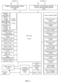
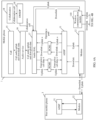
- the electronic device shown in FIG. 2 device operates a software framework as shown in FIG. 3a .
- the software framework is a layered architecture.
- software is divided into several layers, and each layer has a clear role and task.
- the layers communicate with each other through a software interface.
- embodiments of this application take an Android (Android) system as an example to describe a software structure of the mobile phone 1 with the Android system.
- Android Android
- the Android system is divided into five layers, which include an application layer, an application framework layer (or referred to as a system framework layer), a system library and Android runtime, a hardware abstraction layer (hardware abstraction layer, HAL), and a kernel layer from top to bottom.
- an application layer an application framework layer (or referred to as a system framework layer)
- a system library and Android runtime a hardware abstraction layer (hardware abstraction layer, HAL)
- HAL hardware abstraction layer
- kernel layer from top to bottom.
- the application layer includes an application.
- An application related to embodiments of this application includes a call application.
- the call application has a function of making a call in response to a user's operation of making a call or answering a call (for example, tapping an answering key on an incoming call interface), a function of performing incall recording in response to a user's operation of starting recording (for example, tapping a recording key on a call interface), and a function of making an emergency call in response to a user's operation of making an emergency call (for example, selecting an emergency contact to call on an emergency call interface).
- the call application When the user answers a call, or makes a call, or records a call, or makes an emergency call based on the mobile phone 1, the call application generates a corresponding instruction in response to an operation performed by the user, and transmits the instruction to the application framework layer.
- the application layer may further include a collaboration module.
- the collaboration module is enabled and mainly responsible for monitoring a call state and controlling call logic.
- the application framework layer provides an application programming interface (Application Programming Interface, API) and a programming framework for the applications at the application layer.
- the application framework layer further includes some predefined functions.
- the framework layer may include a window manager, a content provider, a view system, a resource manager, a notification manager, a camera service, and the like.
- Modules related to embodiments of this application include a distributed mobile sensing development platform (Distributed Mobile Sensing development platform, DMSDP) and a phone manager.
- DMSDP distributed Mobile Sensing development platform
- the DMSDP assigns identifiers to a speaker and a microphone of the notebook computer 2, so that the speaker and the microphone of the notebook computer 2 serve as virtual devices of the mobile phone 1.
- the DMSDP is further configured to trigger the opening and closing of the transmission path for audio data, which will be described in detail in the following process.
- the phone manager is configured to provide a call function for the mobile phone 1, for example, management of a call state (including connected and hang-up).
- the phone manager provides a service related to a call, including an audio service (Audio Service).
- an audio service Audio Service
- the call application When the user operates on the mobile phone 1 to answer a call, or make a call, or record a call, or make an emergency call, the call application generates a corresponding instruction in response to an operation performed by the user, and transmits the instruction to an audio service of the application framework layer.
- a system library and an Android runtime includes the system library and Android runtime (Android Runtime).
- the system library may include a plurality of functional modules.
- the android runtime is responsible for scheduling and management of the android system, including a kernel library and a virtual machine.
- the system library may include a plurality of functional modules, Modules related to embodiments of this application include audio libraries (Audio Libraries).
- the phone manager merely provides a bridge to access the kernel library for the call application.
- An actual function implementation is completed in the audio libraries.
- audio libraries include an audio service (Audio Service) corresponding to the audio service of the application framework layer.
- the collaboration module may be deployed in the system library, rather than the application layer.
- the Hardware abstraction layer HAL is an interface layer that is between an operating system kernel and a hardware circuit. Modules related to embodiments of this application include an Audio HAL.
- the Audio HAL defines a standard interface that should be implemented by the audio service to invoke the mobile phone to ensure normal running of an audio hardware function.
- the Audio HAL is responsible for truly associating an Audio Ffinger/Audio Policy Service with a hardware device.
- a correspondence between a usage scenario (USECASE) and a pulse code modulation (pulse code modulation, PCM) device identifier is pre-configured in the Audio HAL.
- the USECASE refers to some predefined audio scenarios. For example, record is a common recording scenario, and Voice_call is a voice call scenario.
- the USECASE further has uplink and/or downlink attributes. For example, record is uplink and downlink, that is, a normal recording scene needs to obtain uplink and downlink audio data.
- each USECASE corresponds to an identifier of a PCM device used to implement the scenario.
- the PCM device is considered as a software node configured to cache PCM data (for example, audio data).
- the PCM device is abstracted as a PCM device file, that is, a PCM device file represents a PCM device.
- the Audio HAL can create, open, or close the PCM device file to implement creation, opening or closing of the PCM device.
- the opened PCM device can cache the PCM data, and the Audio HAL can also read PCM data herein.
- the Audio HAL also includes a virtual Modem.
- the virtual Modem is a program written in the Audio HAL. When the program is run, an operation such as opening or closing the PCM device and the path during a collaboration call can be implemented. The details will be described as follows.
- the kernel layer is a layer between hardware and software.
- the PCM device file is stored in the kernel layer.
- the kernel layer further includes at least a display driver, a camera driver, an audio driver, a sensor driver, an ADSP driver, and the like.
- the components included in the application framework layer, the system library, and the runtime layer shown in FIG. 3a do not constitute a specific limitation on the electronic device.
- the electronic device may include more or fewer components than those shown in the figure, or some components may be combined, or some components may be split, or a different component deployment may be used.
- a call process of the mobile phone 1 is as follows.
- the call application When the user answers a call, the call application responds to a user's operation of answering a call on the mobile phone 1 (for example, tapping the answering key on the incoming call interface), generates a call start instruction, and invokes the audio service of the phone manager and the audio service of the audio library.
- the call start instruction is delivered to the Audio HAL, and then is further delivered to the ADSP.
- the ADSP receives the call start instruction, call downlink data transmitted by a call peer mobile phone is received through the Modem and is transmitted to the speaker for playback, and call uplink data is collected by using the microphone and is transmitted to a call peer device through the Modem.
- the call application When the user makes a call, the call application responds to a user's operation of making a call on the mobile phone 1 (for example, entering Phone on a main interface, selecting a related contact, tapping to dial, or the like), and generates a call start instruction after the call peer device is connected.
- the call application invokes the audio service of the phone manager and the audio service of the audio library, the call start instruction is delivered to the Audio HAL, and then is further delivered to the ADSP.
- the ADSP receives the call start instruction, the call downlink data transmitted by the call peer mobile device is received and is transmitted to the speaker for playback, and the call uplink data is collected by using the microphone and is transmitted to the call peer device.
- the ADSP can further transmit the call downlink data to the telephone receiver for playback, or transmit the call downlink data to a wired headset through the headset interface for playback, or transmit the call downlink data to a wireless headset through Bluetooth for playback.
- the call uplink data obtained by the ADSP may further be collected by using a wireless headset or a wired headset connected to the mobile phone 1. This is not limited in embodiments of this application.
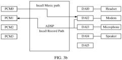
- the ADSP is digital signal processor for processing audio.
- PCM0, PCM1, ..., and PCM3 are PCM devices.
- DAI0 ..., and DAI5 are interfaces, and a headset, a speaker and the like are audio devices.
- the ADSP is configured to connect the PCM device to the interface.
- the path connecting the PCM device and the audio device is referred to as an audio path. It can be understood that the audio path includes a communication part and an interface in the ADSP
- the PCM1 is configured to cache call audio uplink data and call audio downlink data.
- An example of the audio path is an Incall Record path.
- the Incall Record path is an audio path connecting the PCM1 to the microphone and the Modem.
- the PCM0 is configured to cache emergency call data (that is, a piece of fixed audio data)
- the Incall Music path is an audio path connecting the PCMP0 to the Modem.
- the audio path in the ADSP is configured to exchange data with the PCM device, and the interface and the audio device are generally in an opened state after the electronic device is started, the audio path is also opened when the PCM device is opened through the PCM device file.
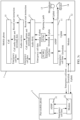
- FIG. 3c shows a process of implementing an incall record function by the mobile phone 1.
- Call audio downlink data transmitted by a peer mobile phone 3 is received by an ADSP 11 of the mobile phone 1 through a Modem12, and is transmitted to a speaker 14 for playback.
- Call audio uplink data collected by using a microphone 13 is obtained and transmitted to the peer mobile phone 3 through the Modem12.
- An ADSP31 and a Modem32 exchange call audio data in the peer mobile phone 3.
- the call application 15 After a recording control is tapped in the incoming call interface displayed by a call application 15 in the mobile phone 1, the call application 15 generates a record start instruction, invokes the audio service in the phone manager and the audio service in the audio libraries (collectively referred to as an audio service 16 in FIG. 3c ), and delivers the record start instruction to an Audio HAL17.
- the Audio HAL17 determines a USECASE corresponding to a call record instruction as a USECASE1 (uplink and downlink), and determines, through a correspondence between the USECASE1 and the PCM1, the PCM device obtaining call audio as the PCM1.
- the Audio HAL17 opens the PCM1 and the Incall Record path by opening a PCM1 device file.
- the Incall Record path transmits the call audio uplink data and the call audio downlink data to the PCM1 for cache.
- the Audio HAL17 reads (read) the PCM1 device file to obtain the call audio uplink data and the call audio downlink data from the PCM1.
- the Audio HAL17 transmits the obtained call audio uplink data and the call audio downlink data to the call application 15 through the audio service in the audio libraries and the audio service in the phone manager (collectively referred to as the audio service 16 in FIG. 3c ).
- the call application 15 stores the call audio uplink data and the call audio downlink data in a preset format, to complete the incall record function.
- 3c shows a process in which the mobile phone 1 implements an emergency call (where the emergency call refers to transmitting fixed audio to a designated phone number, to remind a user hereof to call the police for the user of the mobile phone 1) based on FIG. 3a and FIG. 3b .
- the call application 15 responds to a user's operation of making an emergency call (for example, tapping an emergency call key on a lock screen interface, tapping personal emergency information, and selecting an emergency contact to dial), and writes emergency call data (where the emergency call data is a piece of fixed audio data) into the audio service of the phone manager.
- emergency call data is written from the audio service of the phone manager into the audio service of the audio libraries, and then is written from the audio service of the audio libraries (collectively referred to as the audio service 16 in FIG. 3c ) into the Audio HAL17.
- the Audio HAL17 opens a PCM0 device file, to open the PCM0 and the Incall Music path, and writes the emergency call data into the PCM0.
- the Incall Music path transmits the emergency call data to the Modem12.
- the Modem12 transmits the emergency call data to the peer mobile phone, so that the user of the peer mobile phone as an emergency contact can help the user of the mobile phone 1 to make a call for help.
- the Audio HAL17 in the mobile phone 1 multiplexes the PCM device and the audio path, and exchanges the call audio data with the notebook computer 2.
- Being multiplexed in the multi-screen collaboration scenario means that there is originally a data transmission function to be realized, but in the multi-screen collaboration scenario, the function of call audio data transmission is also to be undertaken.
- the PCM1 is multiplexed to transmit the call audio downlink data to the notebook computer 2.
- a collaboration module 18 and a DMSDP module 19 monitor a call in multi-screen collaboration, and deliver a collaboration call instruction to the Audio HAL17.
- the Audio HAL17 determines the USECASE as an audio call downlink scenario corresponding to PCM1.
- the Audio HAL17 opens the PCM1.
- the PCM1 caches the call audio downlink data transmitted through the Incall Record path, and the call audio uplink data is no longer transmitted.
- the Audio HAL17 transmits the call audio downlink data in the PCM1 to the notebook computer 2 through a wireless communication module 110.
- the Audio HAL17 needs to obtain the downlink data and the uplink data from the PCM1.
- the PCM1 only caches the downlink data in a collaboration call scenario. It can be learned that the record function conflicts with a collaboration call function.
- One way to address the conflict is to perform audio mixing on the uplink data and the downlink data in the Audio HAL17, and then transmit mixed data to the call application 15. It can be understood that addressing the conflict will increase power consumption of the mobile phone 1.
- the PCM0 is multiplexed to receive the call audio uplink data transmitted by the notebook computer 2.
- the Audio HAL17 receives, through the wireless communication module 110, the uplink data transmitted by the notebook computer 2, the uplink data is cached in the PCM0.
- the Incall Music path transmits the uplink data to the Modem 12, and the Modem 12 transmits the uplink data to the peer mobile phone 3.
- embodiments of this application provide the following improvement manners.
- the Audio HAL In addition to configuring the correspondence between the audio call USECASE and the PCM1 (that is, a third PCM device), the Audio HAL also configures correspondences as follows.
- PCM3 that is, the second PCM device.
- the PCM2 device and the PCM3 device are different PCM devices.
- PCM2 and PCM3 are PCM devices different from PCM1.
- the PCM1 is configured to obtain the call audio uplink data and the call audio downlink data.
- the PCM2 is configured to obtain the call audio downlink data.
- the PCM3 is configured to obtain the call audio uplink data.
- the path configured to transmit the call audio downlink data is referred to as a collaboration call downlink path for short
- the path configured to transmit the call audio uplink data is referred to as a collaboration call uplink path for short.
- collaboration call downlink path connects the PCM2 to the Modem.
- collaboration call uplink path connects the PCM3 to the Modem.
- a built-in or external speaker and a microphone of the notebook computer 2 are configured as virtual devices of the mobile phone 1 by the DMSDP.
- the built-in or external speaker of the notebook computer 2 is referred to as a virtual speaker.
- the built-in or external microphone of the notebook computer 2 is referred to as a virtual microphone.
- the USECASE is not a required parameter to be configured. In other words, the USECASE may not be configured, but the correspondence between the collaboration call and the PCM2 and PCM3 is configured.
- correspondence can be configured by using acdb files, XML configuration files, and the like.
- FIG. 1a shows an example of a multi-screen collaboration scenario.
- the mobile phone 1 with a cellular communication capability can enter the multi-screen collaboration mode with 2, 3 and 4 shown in FIG. 1a .
- the mobile phone 1 and the notebook computer 2 enter the multi-screen collaboration mode in an NFC manner.
- NFC manner is only an example of entering the multi-screen collaboration mode, and the multi-screen collaboration mode may also be entered through Bluetooth, wired connection, or the like. Details are not repeated herein.
- the interface for making a call can be entered by operating an interface of the mobile phone 1 or an interface displayed in the collaboration window of the notebook computer 2 as shown in an interface C shown in FIG. 1d , or when there is an incoming call, both the mobile phone 1 and the notebook computer 2 display an incoming call reminder interface, for example, an interface D shown in FIG. 1e .
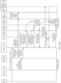
- FIG. 5b(1) and FIG. 5b(2) After the user makes a call on the notebook computer 2, or after the user answers a call on the notebook computer 2, the process shown in FIG. 5b(1) and FIG. 5b(2) is triggered to be implemented, including the following steps: S01: The call application transmits a call operation notification to the Audio HAL.
- the call application responds to an operation of making a call or answering a call, and transmits the call operation notification to the Audio HAL.
- the call application displays as the dialing interface shown in FIG. 1d .
- the user makes a call on the dialing interface.
- the call application responds to the operation of making a call, and transmits, to the Audio HAL, a notification that indicates the operation of making a call.
- the user taps an answering control on the incoming call reminder interface shown in FIG. 1e .
- the call application responds to a tapping operation on the answering control, switches the dialing interface to the call interface, and transmits, to the Audio HAL, a notification of answering a call.
- the call application 15 transmits a notification of the call operation notification to the Audio HAL17, through the audio service in the phone manager and the audio service in the audio libraries (collectively referred to as the audio service 16 in FIG. 6A ).
- the Audio HAL delivers a call establishment instruction to the ADSP in response to the call operation notification.
- the Audio HAL delivers the call establishment instruction to the ADSP through the ADSP driver shown in FIG. 3a .
- S03 Establish a call downlink path and a call uplink path between the ADSP and the Modem.
- the ADSP11 and the Modem12 of the mobile phone 1, and the ADSP31 and the Modem32 of the peer mobile phone establish a call process between the mobile phone 1 and the peer mobile phone 3 based on a cellular communication protocol.
- the call downlink path and the call uplink path are established between the ADSP11 and the Modem12.
- the call audio data can be transmitted on the paths.
- the collaboration module delivers collaboration call instructions to the DMSDP.
- the collaboration module 18 delivers collaboration call instructions to the DMSDP19.
- instructions that instruct the USECASE2 and the USECASE3 can be included in the collaboration call instructions delivered to the Audio HAL17 by the DMSDP19 shown in FIG. 6A .
- the DMSDP16 can deliver instructions that invoke the PCM2 and the PCM3 to the Audio HAL17.
- the instructions that invoke the PCM2 and the PCM3 can be included in the collaboration call instructions delivered to the Audio HAL17 by the DMSDP19.
- the DMSDP monitors the call state to complement and verify a monitoring result of the collaboration module. This can ensure an accuracy of the monitoring result.
- the Audio HAL opens the PCM2 based on the USECASE2 and the pre-configured correspondence.
- the virtual Modem opens (open) the PCM2 device file to open the PCM2. After the PCM2 is opened, as shown in FIG. 5a , the collaboration call downlink path connected between the PCM2 and the Modem is opened.
- S06 is performed by the virtual Modem in the Audio HAL.
- the Audio HAL opens the PCM3 based on the USECASE3 and the pre-configured correspondence.
- the PCM3 device file is opened (open) to open the PCM3.
- the collaboration call uplink path connected between the PCM3 and the Modem is opened.
- S07 is performed by the virtual Modem in the Audio HAL.
- the Audio HAL opens, based on instructions that invoke the PCM2 and the PCM3, the PCM2 device file and the PCM3 device file, to open the PCM2, the PCM3, the collaboration call downlink path and the collaboration call uplink path.
- the PCM2 caches the call audio downlink data transmitted to the ADSP11 by the Modem12.
- the Audio HAL performs a read (read) operation on the PCM2 device to read the call audio downlink data from the PCM2.
- S08 is executed by the virtual Modem in the Audio HAL.
- the Audio Hal transmits the call audio downlink data to the wireless communication module.
- the Audio HAL invokes the wireless communication module 110 and transmits the call audio downlink data to the notebook computer 2.
- the speaker of the notebook computer 2 plays the call audio downlink data.
- S09 is performed by the virtual Modem in the Audio HAL. In some other implementations, S09 is performed by an audio hardware management module in the Audio HAL.
- S10 The Audio HALreceives the call audio uplink data from the wireless communication module. It can be understood that, the user voice (that is, the call audio uplink data) collected by the notebook computer 2 is cached, and transmitted to the wireless communication module 110.
- the Audio HAL17 invokes the wireless communication module to receive the call audio uplink data.
- the Audio HAL performs a write (write) operation on the PCM3 device file to cache data in the PCM3.
- S10 and S11 are performed by the virtual Modem in the Audio HAL. In some other implementations, S10 and S11 are performed by the audio hardware management module in the Audio HAL.
- the call application delivers a recording operation notification to the Audio HAL.
- the user taps a recording control F in a collaboration call interface E of the notebook computer 2. Then the notebook computer 2 transmits the recording operation notification to the collaboration module 18 through the wireless communication module 110 of the mobile phone 1. The collaboration module 18 transmits the recording operation notification to the call application 15 of the mobile phone 1. The call application 15 delivers the recording operation notification to the Audio HAL17 through the audio service 16, as shown in FIG. 5b(1) and FIG. 5b(2) .
- the user taps the recording control F in the collaboration call interface E of the notebook computer 2. Then the notebook computer 2 transmits the recording operation notification to the collaboration module 18 through the wireless communication module 110 of the mobile phone 1. The collaboration module 18 of the mobile phone 1 delivers the recording operation notification to the Audio HAL17 through the DMSDP19 (not shown in FIG. FIG. 5b(1) and FIG. 5b(2) ).
- the Audio HAL determines the USECASE as the USECASE1 based on the recording operation notification and the pre-configured correspondence.
- the Audio HAL performs a read (read) operation on the PCM1 device file to read the call audio uplink data and the call audio downlink data from the PCM1.
- the Audio HAL transmits the call audio uplink data and the call audio downlink data to the call application.
- the Audio HAL17 transmits the call audio uplink data and the call audio downlink data to the call application 15 through the audio service in the audio libraries and the audio service in the phone manager (collectively referred to as the audio service 16 in FIG. 6A ).
- the user taps the recording control F (pressed) in the collaboration call interface E of the notebook computer 2 to disable the recording function, or the user taps a call end control G in the collaboration call interface E to end the call. Then the notebook computer 2 transmits a record end notification or a call end notification to the collaboration module 18 of the mobile phone 1 through the wireless communication module 110.
- the collaboration module 18 of the mobile phone 1 transmits the recording operation notification to the call application 15 of the mobile phone 1.
- the call application 15 delivers the incall record end notification or the call end notification to the Audio HAL17 through the audio service 16.
- the user taps the recording control F (pressed) in the collaboration call interface E of the notebook computer 2 to disable the recording function, or the user taps the call end control G in the collaboration call interface E to end the call.
- the notebook computer 2 transmits the record end notification or the call end notification to the collaboration module 18 of the mobile phone 1 through the wireless communication module 110.
- the collaboration module 18 delivers the incall record end notification or the call end notification to the Audio HAL17 through the DMSDP19.
- the user can further tap the recording control F (pressed) in the call interface of the mobile phone 1 (the same as the call interface E in FIG. 6B ) to disable the recording function, or the user taps the call end control G to end the call.
- the call application 15 responds to the incall record end operation or the call end operation, and transmits the incall record end notification or the call end notification to the Audio HAL17.
- S12 to S17 are optional steps, and are not performed in a call process when the call record function is not enabled.
- an execution body of S12 to S17 is the audio hardware management module in the Audio HAL.
- the collaboration module before S18, notifies the DMSDP after the end of a call is monitored. After receiving the notification and monitoring the end of the call, the DMSDP delivers the call end notification to the Audio HAL.
- the PCM2 is closed by closing (close) the PCM2 FILE. After the PCM2 is closed, the collaboration downlink path cannot transmit data to the PCM2. This means that the collaboration call downlink path is closed.
- the PCM3 and the collaboration call uplink path are closed by closing the PCM3 file.
- a PCM device and a path with a function occupied are not multiplexed to transmit the call audio data between collaboration devices. Therefore, the conflicts caused by multiplexing a PCM device and a path can be avoided, and further avoid operations including audio mixing and forwarding caused by conflicts, thereby reducing power consumption of the electronic device.
- Described in detail are examples of a transmission method for call audio data according to embodiments of this application. It may be understood that to implement the foregoing functions, the electronic device includes corresponding hardware and/or software modules for performing the functions.
- the electronic device includes corresponding hardware and/or software modules for performing the functions.
- a person skilled in the art should be easily aware that, in combination with the units and algorithm steps of the examples described in the embodiments disclosed in this specification, this application can be implemented by hardware or a combination of hardware and computer software. Whether a function is performed by hardware or computer software driving hardware depends on particular applications and design constraints of the technical solutions. A person of skill in the art may use different methods to implement the described functions with reference to embodiments for each particular application, but it should not be considered that the implementation goes beyond the scope of this application.
- functional modules of the electronic device may be divided based on the foregoing method examples.
- functional modules may be divided based on functions, such as ADSP and Modem, or two or more functions may be integrated into one module.
- the integrated module may be implemented in a form of hardware, or may be implemented in a form of a software functional module. It should be noted that module division in this embodiment of this application is an example and is merely logical function division. During actual implementation, there may be another division manner.
- the electronic device is configured to perform the call audio device data transmission method, and therefore may achieve the same effect as the foregoing method Embodiments of this application further provide a computer-readable storage medium.
- a computer program is stored in the computer-readable storage medium. When the computer program is executed by a processor, the method for transmitting the call audio data according to any one of the embodiments is performed by the processor.
- Embodiments of this application further provide a computer program product.
- a computer is enabled to perform the related steps, to implement the method for transmitting the call audio data in the foregoing embodiments.
- an embodiment of this application further provides an apparatus.
- the apparatus may specifically be a chip, an assembly or a module.
- the apparatus may include a processor and a memory connected to each other.
- the memory is configured to store computer-executable instructions.
- the processor may execute the computer-executable instructions stored in the memory to cause a chip to implement method for transmitting the call audio data in the above method embodiments.
- the electronic device, the computer-readable storage medium, the computer program product, or the chip provided in the embodiments may be configured to perform the corresponding method provided above. Therefore, for beneficial effects that can be achieved, refer to the beneficial effects of the corresponding method provided above. Details are not described herein again.
- the disclosed apparatus and method may be implemented in other manners.
- the described apparatus embodiment is merely exemplary.
- the module or the unit division is merely a logical function division and may be other division during actual implementation.
- a plurality of units or components may be combined or integrated into another apparatus, or some features may be ignored or not performed.
- the shown or discussed mutual couplings or direct couplings or communication connections may be implemented through some interfaces.
- the indirect couplings or communication connections between the apparatus or units may be implemented in electronic, mechanical, or other forms.
- the units described as separate parts may or may not be physically separate, and parts displayed as units may be one or more physical units, may be located in one place, or may be distributed in multiple different places. Some or all of the units may be selected based on actual requirements to achieve the objectives of the solutions of the embodiments.
- function units in the embodiments of this application may be integrated into one processing unit, or each of the units may exist alone physically, or two or more units may be integrated into one unit.
- the integrated unit may be implemented in the form of hardware, or may be implemented in the form of a software function unit.
- the integrated unit may be stored in a readable storage medium.
- the software product is stored in a storage medium and includes several instructions for instructing a device (which may be a single-chip microcomputer, a chip, or the like) or a processor (processor) to perform all or some of the steps of the methods described in the embodiments of the present invention.
- the foregoing storage medium includes: any medium that can store program code, such as a USB flash drive, a removable hard disk, a read-only memory (read only memory, ROM), a random access memory (random access memory, RAM), a magnetic disk, a compact disc, or the like.
- program code such as a USB flash drive, a removable hard disk, a read-only memory (read only memory, ROM), a random access memory (random access memory, RAM), a magnetic disk, a compact disc, or the like.
Abstract
Description
- This application claims priority to
Chinese Patent Application No. 202210023402.8, filed with the China National Intellectual Property Administration on January 10, 2022 - This application relates to the field of communication technologies, and in particular, to a method for transmitting call audio data and an apparatus.
- Call functions based on a cellular communication network is a common function of mobile phones, but electronic devices not supporting a cellular network do not have this function.
- However, in a multi-screen collaboration mode, a second electronic device in collaboration with a first electronic device such as a mobile phone that supports cellular communication can implement the call function based on the cellular communication network.
- Embodiments of this application provide a method for transmitting call audio data and an apparatus, to implement call audio data transmission between different electronic devices.
- To achieve the foregoing objective, this application provides the following technical solutions. According to a first aspect, this application provides a method for transmitting call audio data. The method is applied to a first electronic device. The first electronic device includes a first PCM device, a second PCM device and a third PCM device. The first PCM device, the second PCM device and the third PCM device are configured to cache PCM audio data. The method includes: establishing a call with a peer electronic device in response to a call operation, where the first electronic device and the second electronic device are in a multi-screen collaboration mode, receiving call audio downlink data transmitted by the peer electronic device, storing the call audio downlink data transmitted in the first PCM device, transmitting the call audio downlink data in the first PCM device to the second electronic device, receiving call audio uplink data transmitted by the second electronic device, storing the call audio uplink data transmitted by the second electronic device in the second PCM device, transmitting the call audio uplink data in the second PCM device to the peer electronic device, and storing the call audio uplink data and the call audio downlink data in the third PCM device in response to an incall record operation. The first PCM device, the second PCM device and the third PCM device are different. It can be learned that, different PCM devices are used to respectively implement transmission and recording of the call audio uplink data and call audio downlink data, so that a possibility of cache data conflicts in a PCM device caused by multiplexing a PCM device can be reduced. Furthermore, a problem of increased power consumption caused by solving conflicts for an electronic device can further be avoided.
- In some implementations, the establishing a call with a peer electronic device includes establishing a call with the peer electronic device through a modulator-demodulator Modem. The storing the call audio downlink data in the first PCM device includes opening the first PCM device and a collaboration call downlink path by opening a first PCM device file. The collaboration call downlink path is configured to connect the first PCM device and the Modem. Opening the first PCM device through the first PCM device file can simplify operations, correspond to operation logics of a software system and have good compatibility. The collaboration call downlink path is configured to connect the first PCM device to the Modem. Therefore, opening the path can implement a function of transmitting the call audio downlink data from the Modem to the first PCM device through the collaboration call downlink path, and further to the second electronic device, to further reduce complexity of implementation.
- In some implementations, the transmitting the call audio downlink data to the second electronic device includes reading the call audio downlink data from the first PCM device by performing a read operation on the first PCM device file; and transmitting the call audio downlink data to the second electronic device. Performing the operation on the first PCM device to read the data in the first PCM device can simplify operations, and have good compatibility.
- In some implementations, the establishing a call with a peer electronic device includes establishing a call with the peer electronic device through the Modem. The storing the call audio uplink data in the second PCM device and transmitting the call audio uplink data in the second PCM device to the peer electronic device includes opening the second PCM device and a collaboration call uplink path by opening a second PCM device file, receiving the call audio uplink data transmitted by the second electronic device; and storing the call audio uplink data in the second PCM device by performing a write operation on the second PCM device file. Opening the second PCM device file to open the second PCM device and the collaboration call uplink path. Performing the operation on the second PCM device file to write the call audio uplink data into the second PCM device. Because the collaboration call uplink path is configured to connect the second PCM device and the Modem, the call audio uplink data is transmitted from the second PCM device to the Modem through the collaboration call uplink path, and further to a peer mobile phone, to further reduce complexity to implement.
- In some implementations, the establishing a call with a peer electronic device includes: establishing the call with the peer electronic device through the Modem. The storing the call audio uplink data and the call audio downlink data in the third PCM device includes: opening the third PCM device and an incall record Incall Record path by opening a third PCM device file. The incall record Incall Record path is configured to connect the third PCM device and the Modem, to further reduce complexity to implement.
- In some implementations, the method further includes: obtaining the call audio uplink data and the call audio downlink data from the third PCM device by reading the third PCM device file, and recording the call audio downlink data and the call audio uplink data. It can be learned that the third PCM device can provide the call audio uplink data and the call audio downlink data for a subsequent recording, to avoid operations including audio mixing, to reduce power consumption. In some implementations, the method further includes: closing, in response to an incall record end operation or a call end operation, the third PCM device by closing the third PCM device file. Closing the PCM device through the PCM device file can simplify operations, and have good compatibility.
- In some implementations, the method further includes: in response to the call end operation, closing the first PCM device by closing the first PCM device file, and closing the second PCM device by closing the second PCM device file. Closing the PCM device through the PCM device file can simplify operations, and have good compatibility.
- In some implementations, before the storing the call audio downlink data transmitted by the peer electronic device in the first PCM device, and the storing the call audio uplink data transmitted by the second electronic device in the second PCM device, the method further includes: determining the PCM device corresponding to the downlink call scenario in the multi-screen collaboration mode as the first PCM device, and the PCM device corresponding to the uplink call scenario in the multi-screen collaboration mode as the second PCM device, by querying a correspondence between a USECASE and a PCM device. It can be learned that the method can pre-configure a correspondence and modify the correspondence through the configuration, to modify a PCM device used in a scenario, to improve flexibility of the audio data transmission method.
- In some implementations, before the establishing a call with a peer electronic device in response to a call operation, the method further includes displaying a collaboration window. The collaboration window includes a dialing interface or an incoming call interface displayed on the second electronic device. The establishing a call with a peer electronic device in response to a call operation includes establishing a call with the peer electronic device in response to the call operation on the dialing interface or the incoming call interface. Implementing a call function based on the collaboration window operation can improve user experience.
- In some implementations, before the displaying a collaboration window, the method further includes starting the multi-screen collaboration mode with the second electronic device through near field communication NFC, Bluetooth, or in a wired manner. Diversity in implementations of the multi-screen collaboration mode can further improve user experience.
- According to a second aspect, this application provides an electronic device, including a memory and at least one processor. The memory is configured to store a program. The processor is configured to execute the program, to implement the method for transmitting call audio data according to the first aspect of this application.
- According to a third aspect, this application provides a computer storage medium configured to store a computer program. The computer program when executed is configured to implement the method for transmitting call audio data according to the first aspect of this application. According to a fourth aspect, this application provides a computer program product. When operated on the computer, the computer program product is configured to implement the method for transmitting call audio data according to the first aspect of this application.
-
-
FIG. 1a is an exemplary diagram of a scenario of performing multi-screen collaboration on a plurality of electronic devices; -
FIG. 1b is an exemplary diagram of a manner of opening multi-screen collaboration between a mobile phone and a notebook computer; -
FIG. 1c is an exemplary diagram in which a notebook computer enters a multi-screen collaboration mode; -
FIG. 1d is an exemplary diagram of a dialing interface when a mobile phone and a notebook computer are in a multi-screen collaboration mode; -
FIG. 1e is an exemplary diagram of an incoming call interface when a mobile phone and a notebook computer are in a multi-screen collaboration mode; -
FIG. 2 is an exemplary diagram of a structure of an electronic device according to an embodiment of this application; -
FIG. 3a is an exemplary diagram of a software framework run in an electronic device according to an embodiment of this application; -
FIG. 3b is an exemplary diagram of audio paths; -
FIG. 3c is an exemplary diagram of audio data transmission when the audio paths shown inFIG. 3b during a call and making an emergency call; -
FIG. 4A andFIG. 4B is an exemplary diagram of another call audio data transmission in a multi-screen collaboration mode according to an embodiment of this application; -
FIG. 5a is an exemplary diagram of audio paths according to an embodiment of this application; -
FIG. 5b(1) andFIG. 5b(2) is a flowchart of a method for transmitting call audio data according to an embodiment of this application; and -
FIG. 6A andFIG. 6B is still another audio data transmission in a multi-screen collaboration mode according to an embodiment of this application. - The following clearly and completely describes technical solutions in embodiments of the present application with reference to the accompanying drawings in the embodiments of the present application. Terms used in the following embodiments are only intended to describe particular embodiments, and are not intended to limit this application. As used in this specification and the claims of this application, a singular expression form, "one", "a/an", "the", "foregoing", or "this", is intended to also include "one or more" expression form, unless clearly indicated to the contrary in the context. It should be further understood that, in embodiments of this application, the term "and/or" describes an association relationship for describing associated objects and represents that three relationships may exist. For example, A and/or B may represent the following three cases: Only A exists, both A and B exist, and only B exists, where A and B each may be in a singular or plural form. The character "/" in this specification generally indicates an "or" relationship between the associated objects.
- Reference to "one embodiment" or "some embodiments" described in this specification means that a specific characteristic, structure or feature described in combination with this embodiment is included in one or more embodiments of this application. Therefore, the statements "in one embodiment", "in some embodiments", "in some other embodiments", "in other embodiments", and the like in the differences in this specification do not necessarily refer to the same embodiment, but mean "one or more but not all embodiments", unless otherwise specially emphasized in other ways. The terms "include", "contain", "have" and their variations mean "including but not limited to", unless otherwise specially emphasized in other ways.
- A plurality of involved in the embodiments of this application refers to two or more. It should be noted that, in descriptions of the embodiments of this application, terms such as "first" and "second" are merely used for distinguishing descriptions, and cannot be understood as an indication or implication of relative importance, or an indication or implication of a sequence.
FIG. 1a shows an example of a scenario of multi-device collaboration. Amobile phone 1 and anotebook computer 2, a personal digital assistant (Personal Digital Assistant, PDA) 3 and alarge screen 4 can respectively enter a multi-screen collaboration mode. - In the multi-screen collaboration mode, the
notebook computer 2, thePAD 3 and thelarge screen 4 that have no cellular communication capability, through a cellular communication capability of themobile phone 1, can perform cellular network-based communication, including but not limited to making a call, answering a call, and making a cellular network-based video call. - Taking
FIG. 1b as an example, in a case that themobile phone 1 enables a near field communication (Near Field Communication, NFC) function, after approaching a touchpad of thenotebook computer 2 that enables the NFC function, themobile phone 1 displays a connection interface with thenotebook computer 2. As shown inFIG. 1c , after a "connect" control on the connection interface is tapped, themobile phone 1 and thenotebook computer 2 enters the multi-screen collaboration mode. - As shown in
FIG. 1c , in the multi-screen collaboration mode, a collaboration window A of themobile phone 1 is displayed on thenotebook computer 2, and displayed content of the collaboration window A and content currently displayed on themobile phone 1 are the same. TakingFIG. 1c as an example, themobile phone 1 currently displays a desktop, and a collaboration window A of thenotebook computer 2 displays a same desktop. - In the collaboration window A of the
notebook computer 2, an operation that is the same as the operation on themobile phone 1 can be performed by clicking a mouse or by tapping. For example, as shown inFIG. 1c , in a case that a desktop of themobile phone 1 is displayed in the collaboration window A, a cursor of the mouse is placed in the collaboration window A of thenotebook computer 2, and two fingers slide on the touchpad of thenotebook computer 2, so that a plurality of desktops of the mobile phone can be switched in the collaboration window A. - In another example, on the
notebook computer 2, an icon B of a telephone application displayed in the collaboration window A is tapped or is clicked by using a mouse to enter a collaboration dialing interface C. As shown inFIG. 1d , on thenotebook computer 2, a call can be made on the collaboration dialing interface C by tapping or by clicking the mouse. - As shown in
FIG. 1e , in the multi-screen collaboration mode, when themobile phone 1 is called, a collaboration incoming call interface D is displayed in a collaboration desktop A of thenotebook computer 2, and a call can be answered on the collaboration incoming call interface D by tapping or by clicking a mouse. - In the multi-screen collaboration mode, because the
notebook computer 2 makes or answers a call through a cellular communication network of themobile phone 1, after the call is connected, themobile phone 1 and thenotebook computer 2 need to exchange call audio data. - Embodiments of this application provide a method for transmitting call audio data, to resolve a problem of audio data transmission between devices in the multi-screen collaboration mode in a multi-screen collaboration scenario.
- Embodiments of this application are applied to an electronic device with a cellular communication function. In some embodiments, the electronic device may be a mobile phone (as shown in
FIG. 2 ), a tablet computer, a desktop computer, a laptop computer, a notebook computer, an ultra-mobile personal computer (Ultra-mobile Personal Computer, UMPC), a handheld computer, a netbook, a personal digital assistant (Personal Digital Assistant, PDA), a wearable electronic device, a smart watch, or the like. - The mobile phone shown in
FIG. 2 includes aprocessor 110, anexternal memory interface 120, aninternal memory 121, a universal serial bus (universal serial bus, USB)interface 130, acharging management module 140, apower management module 141, abattery 142, anantenna 1, anantenna 2, amobile communication module 150, awireless communication module 160, and anaudio module 170, aspeaker 170A, aphone receiver 170B, amicrophone 170C, a headset jack 170D, asensor module 180, a key 190, amotor 191, anindicator 192, a camera 193, adisplay screen 194, a subscriber identity module (subscriber identity module, SIM)card interface 195, and the like. Thesensor module 180 may include apressure sensor 180A, agyroscope sensor 180B, a barometric pressure sensor 180C, amagnetic sensor 180D, anacceleration sensor 180E, arange sensor 180F, aproximity light sensor 180G, afingerprint sensor 180H, atemperature sensor 180J, atouch sensor 180K, an ambientlight sensor 180L, abone conduction sensor 180M, and the like. It may be understood that the schematic structure in this embodiment constitutes no specific limitation on the electronic device. In some other embodiments, the electronic device may include more or fewer components than those shown in the figure, or some components may be combined, or some components may be split, or components are arranged in different manners. The components in the portrait may be implemented by hardware, software, or a combination of software and hardware. - The
processor 110 may include one or more processing units. For example, theprocessor 110 may include an application processor (application processor, AP), a modem processor, a graphics processing unit (graphics processing unit, GPU), an image signal processor (image signal processor, ISP), a controller, a video codec, a digital signal processor (digital signal processor, DSP), an audio signal processor (audio signal processor, ADSP), a baseband processor, and/or a neural-network processing unit (neural-network processing unit, NPU). Different processing units may be separate devices, or may be integrated into one or more processors. - A memory may also be disposed in the
processor 110, configured to store instructions and data. In some embodiments, the memory inprocessor 110 is a cache memory. The memory may store instructions or data recently used or cyclically used by theprocessor 110. If theprocessor 110 needs to use the instruction or the data again, the processor may directly invoke the instruction or the data from the memory. Repeated access is avoided, and waiting time of theprocessor 110 is reduced, thereby improving system efficiency. - In some embodiments, the
processor 110 may include one or more interfaces. The interface may include an inter-integrated circuit (inter-integrated circuit, I2C) interface, an inter-integrated circuit sound (inter-integrated circuit sound, I2S) interface, a pulse code modulation (pulse code modulation, PCM) interface, a universal asynchronous receiver/transmitter (universal asynchronous receiver/transmitter, UART) interface, a mobile industry processor interface (mobile industry processor interface, MIPI), a general-purpose input/output (general-purpose input/output, GPIO) interface, a subscriber identity module (subscriber identity module, SIM) interface, and/or a universal serial bus (universal serial bus, USB) interface, and the like. - The I2S interface may be configured to perform audio communication. In some embodiments, the
processor 110 may include a plurality of I2S buses. Theprocessor 110 may be coupled to theaudio module 170 through the I2S bus to implement communication between theprocessor 110 and theaudio module 170. In some embodiments, theaudio module 170 may transmit an audio signal to thewireless communication module 160 through the I2S interface, to perform a function of answering a call through a Bluetooth headset. - The PCM interface may also be configured to perform audio communication, to sample, quantize, and encode an analog signal. In some embodiments, the
audio module 170 may be coupled to thewireless communication module 160 through a PCM bus interface. In some embodiments, theaudio module 170 may also transfer an audio signal to thewireless communication module 160 through the PCM interface, to perform the function of answering a call through the Bluetooth headset. Both the I2S interface and the PCM interface may be configured to perform audio communication. - The UART interface is a universal serial data bus and is configured to perform asynchronous communication. The bus may be a bidirectional communication bus. The bus converts data to be transmitted between serial communication and parallel communication. In some embodiments, the UART interface is usually configured to connect the
processor 110 to thewireless communication module 160. For example, theprocessor 110 communicates with a Bluetooth module in thewireless communication module 160 through the UART interface, to perform a Bluetooth function. In some embodiments, theaudio module 170 may transfer an audio signal to thewireless communication module 160 through the UART interface, to perform a function of playing music through the Bluetooth headset. - It can be understood that an interface connection relationship between the modules illustrated in this embodiment is merely an example for description, and does not constitute a limitation on a structure of the electronic device. In some other embodiments of this application, the electronic device may alternatively use an interface connection manner different from that in the foregoing embodiment, or use a combination of a plurality of interface connection manners.
- A wireless communication function of the electronic device may be implemented by using the
antenna 1, theantenna 2, themobile communication module 150, thewireless communication module 160, the modem processor, the baseband processor, and the like. - The
antenna 1 and theantenna 2 are configured to transmit and receive an electromagnetic wave signal. Each antenna in the electronic device may be configured to cover one or more communication frequency bands. Different antennas may further be multiplexed to improve utilization of the antennas. For example, anantenna 1 may be multiplexed as a diversity antenna of a wireless local area network. In some other embodiments, the antennas may be used with a tuning switch. - The
mobile communication module 150 can provide a wireless communication solution including such as 2G/3G/4G/5G applied on the electronic device. Themobile communication module 150 may include at least one filter, a switch, a power amplifier, a low noise amplifier (low noise amplifier, LNA), and the like. Themobile communication module 150 may receive an electromagnetic wave by using theantenna 1, perform processing such as filtering and amplification on the received electromagnetic wave, and send the electromagnetic wave to the modem processor for demodulation. Themobile communication module 150 may further amplify a signal modulated by the modem processor, and convert the signal into an electromagnetic wave by using theantenna 1 for radiation. In some embodiments, at least some functional modules of themobile communication module 150 may be disposed in theprocessor 110. In some embodiments, at least some of the functional modules of themobile communication module 150 may be disposed in a same device as at least some of modules of theprocessor 110. - The modulation and demodulation processor may include a modulator and a demodulator. The modulator is configured to modulate a low frequency baseband signal to be sent into a medium and high frequency signal. The demodulator is configured to demodulate the received electromagnetic wave signal into a low-frequency baseband signal. Then the demodulator transfers the low-frequency baseband signal obtained through demodulation to the baseband processor for processing. The low-frequency baseband signal is processed by the baseband processor and then transferred to an application processor. The application processor outputs a sound signal through an audio device (which is not limited to the
speaker 170A, thetelephone receiver 170B, and the like), or displays an image or a video through thedisplay screen 194. In some embodiments, the modulation and demodulation processor may be an independent device. In some other embodiments, the modem processor may be independent of theprocessor 110, and is disposed in a same device as themobile communication module 150 or another functional module. - The electronic device shown in
FIG. 2 device operates a software framework as shown inFIG. 3a . The software framework is a layered architecture. In the layered architecture, software is divided into several layers, and each layer has a clear role and task. The layers communicate with each other through a software interface. - For convenience of description, embodiments of this application take an Android (Android) system as an example to describe a software structure of the
mobile phone 1 with the Android system. - Specifically, in some embodiments, the Android system is divided into five layers, which include an application layer, an application framework layer (or referred to as a system framework layer), a system library and Android runtime, a hardware abstraction layer (hardware abstraction layer, HAL), and a kernel layer from top to bottom.
- The application layer includes an application. An application related to embodiments of this application includes a call application.
- The call application has a function of making a call in response to a user's operation of making a call or answering a call (for example, tapping an answering key on an incoming call interface), a function of performing incall recording in response to a user's operation of starting recording (for example, tapping a recording key on a call interface), and a function of making an emergency call in response to a user's operation of making an emergency call (for example, selecting an emergency contact to call on an emergency call interface).
- When the user answers a call, or makes a call, or records a call, or makes an emergency call based on the
mobile phone 1, the call application generates a corresponding instruction in response to an operation performed by the user, and transmits the instruction to the application framework layer. In some implementations, the application layer may further include a collaboration module. When themobile phone 1 and thenotebook computer 2 are in a multi-screen collaboration connection, the collaboration module is enabled and mainly responsible for monitoring a call state and controlling call logic. - The application framework layer provides an application programming interface (Application Programming Interface, API) and a programming framework for the applications at the application layer. The application framework layer further includes some predefined functions. As shown in
FIG. 3a , the framework layer may include a window manager, a content provider, a view system, a resource manager, a notification manager, a camera service, and the like. Modules related to embodiments of this application include a distributed mobile sensing development platform (Distributed Mobile Sensing development platform, DMSDP) and a phone manager. - With reference to a multi-screen collaboration scenario shown in
FIG. 1c to FIG. 1e , the DMSDP assigns identifiers to a speaker and a microphone of thenotebook computer 2, so that the speaker and the microphone of thenotebook computer 2 serve as virtual devices of themobile phone 1. In addition, the DMSDP is further configured to trigger the opening and closing of the transmission path for audio data, which will be described in detail in the following process. - The phone manager is configured to provide a call function for the
mobile phone 1, for example, management of a call state (including connected and hang-up). - Specifically, the phone manager provides a service related to a call, including an audio service (Audio Service). When the user operates on the
mobile phone 1 to answer a call, or make a call, or record a call, or make an emergency call, the call application generates a corresponding instruction in response to an operation performed by the user, and transmits the instruction to an audio service of the application framework layer. - A system library and an Android runtime includes the system library and Android runtime (Android Runtime). The system library may include a plurality of functional modules. The android runtime is responsible for scheduling and management of the android system, including a kernel library and a virtual machine.
- The system library may include a plurality of functional modules, Modules related to embodiments of this application include audio libraries (Audio Libraries). The phone manager merely provides a bridge to access the kernel library for the call application. An actual function implementation is completed in the audio libraries. For example, audio libraries include an audio service (Audio Service) corresponding to the audio service of the application framework layer.
- In some other implementations, the collaboration module may be deployed in the system library, rather than the application layer.
- The Hardware abstraction layer HAL is an interface layer that is between an operating system kernel and a hardware circuit. Modules related to embodiments of this application include an Audio HAL. The Audio HAL defines a standard interface that should be implemented by the audio service to invoke the mobile phone to ensure normal running of an audio hardware function. The Audio HAL is responsible for truly associating an Audio Ffinger/Audio Policy Service with a hardware device.
- As shown in
FIG. 3a , a correspondence between a usage scenario (USECASE) and a pulse code modulation (pulse code modulation, PCM) device identifier is pre-configured in the Audio HAL. The USECASE refers to some predefined audio scenarios. For example, record is a common recording scenario, and Voice_call is a voice call scenario. The USECASE further has uplink and/or downlink attributes. For example, record is uplink and downlink, that is, a normal recording scene needs to obtain uplink and downlink audio data. In the correspondence between the USECASE and the PCM device identifier, each USECASE corresponds to an identifier of a PCM device used to implement the scenario. - Generally, the PCM device is considered as a software node configured to cache PCM data (for example, audio data). The PCM device is abstracted as a PCM device file, that is, a PCM device file represents a PCM device. The Audio HAL can create, open, or close the PCM device file to implement creation, opening or closing of the PCM device. The opened PCM device can cache the PCM data, and the Audio HAL can also read PCM data herein.
- As shown in
FIG. 3a , the Audio HAL also includes a virtual Modem. The virtual Modem is a program written in the Audio HAL. When the program is run, an operation such as opening or closing the PCM device and the path during a collaboration call can be implemented. The details will be described as follows. - The kernel layer is a layer between hardware and software. The PCM device file is stored in the kernel layer. The kernel layer further includes at least a display driver, a camera driver, an audio driver, a sensor driver, an ADSP driver, and the like.
- It is to be understood that the components included in the application framework layer, the system library, and the runtime layer shown in
FIG. 3a do not constitute a specific limitation on the electronic device. In an actual application, the electronic device may include more or fewer components than those shown in the figure, or some components may be combined, or some components may be split, or a different component deployment may be used. - In an implementation, based on the software framework shown in
FIG. 3a and a structure ofhardware 1 of the mobile phone, a call process of themobile phone 1 is as follows. - When the user answers a call, the call application responds to a user's operation of answering a call on the mobile phone 1 (for example, tapping the answering key on the incoming call interface), generates a call start instruction, and invokes the audio service of the phone manager and the audio service of the audio library. The call start instruction is delivered to the Audio HAL, and then is further delivered to the ADSP. After the ADSP receives the call start instruction, call downlink data transmitted by a call peer mobile phone is received through the Modem and is transmitted to the speaker for playback, and call uplink data is collected by using the microphone and is transmitted to a call peer device through the Modem.
- When the user makes a call, the call application responds to a user's operation of making a call on the mobile phone 1 (for example, entering Phone on a main interface, selecting a related contact, tapping to dial, or the like), and generates a call start instruction after the call peer device is connected. After the call application invokes the audio service of the phone manager and the audio service of the audio library, the call start instruction is delivered to the Audio HAL, and then is further delivered to the ADSP. After the ADSP receives the call start instruction, the call downlink data transmitted by the call peer mobile device is received and is transmitted to the speaker for playback, and the call uplink data is collected by using the microphone and is transmitted to the call peer device.
- In some scenarios, the ADSP can further transmit the call downlink data to the telephone receiver for playback, or transmit the call downlink data to a wired headset through the headset interface for playback, or transmit the call downlink data to a wireless headset through Bluetooth for playback. In this case, the call uplink data obtained by the ADSP may further be collected by using a wireless headset or a wired headset connected to the
mobile phone 1. This is not limited in embodiments of this application. - The ADSP is digital signal processor for processing audio.
- As shown in
FIG. 3b , PCM0, PCM1, ..., and PCM3 are PCM devices. DAI0 ..., and DAI5 are interfaces, and a headset, a speaker and the like are audio devices. The ADSP is configured to connect the PCM device to the interface. The path connecting the PCM device and the audio device is referred to as an audio path. It can be understood that the audio path includes a communication part and an interface in the ADSP - It is assumed that the PCM1 is configured to cache call audio uplink data and call audio downlink data. An example of the audio path is an Incall Record path. The Incall Record path is an audio path connecting the PCM1 to the microphone and the Modem. It is assumed that the PCM0 is configured to cache emergency call data (that is, a piece of fixed audio data), the Incall Music path is an audio path connecting the PCMP0 to the Modem.
- It can be understood that, because the audio path in the ADSP is configured to exchange data with the PCM device, and the interface and the audio device are generally in an opened state after the electronic device is started, the audio path is also opened when the PCM device is opened through the PCM device file.
- Based on
FIG. 3a andFIG. 3b ,FIG. 3c shows a process of implementing an incall record function by themobile phone 1. - Call audio downlink data transmitted by a peer
mobile phone 3 is received by anADSP 11 of themobile phone 1 through a Modem12, and is transmitted to aspeaker 14 for playback. Call audio uplink data collected by using amicrophone 13 is obtained and transmitted to the peermobile phone 3 through the Modem12. An ADSP31 and a Modem32 exchange call audio data in the peermobile phone 3. - After a recording control is tapped in the incoming call interface displayed by a
call application 15 in themobile phone 1, thecall application 15 generates a record start instruction, invokes the audio service in the phone manager and the audio service in the audio libraries (collectively referred to as anaudio service 16 inFIG. 3c ), and delivers the record start instruction to an Audio HAL17. - The Audio HAL17 determines a USECASE corresponding to a call record instruction as a USECASE1 (uplink and downlink), and determines, through a correspondence between the USECASE1 and the PCM1, the PCM device obtaining call audio as the PCM1.
- The Audio HAL17 opens the PCM1 and the Incall Record path by opening a PCM1 device file. The Incall Record path transmits the call audio uplink data and the call audio downlink data to the PCM1 for cache. The Audio HAL17 reads (read) the PCM1 device file to obtain the call audio uplink data and the call audio downlink data from the PCM1. The Audio HAL17 transmits the obtained call audio uplink data and the call audio downlink data to the
call application 15 through the audio service in the audio libraries and the audio service in the phone manager (collectively referred to as theaudio service 16 inFIG. 3c ). Thecall application 15 stores the call audio uplink data and the call audio downlink data in a preset format, to complete the incall record function.FIG. 3c shows a process in which themobile phone 1 implements an emergency call (where the emergency call refers to transmitting fixed audio to a designated phone number, to remind a user hereof to call the police for the user of the mobile phone 1) based onFIG. 3a andFIG. 3b . When the user makes an emergency call, thecall application 15 responds to a user's operation of making an emergency call (for example, tapping an emergency call key on a lock screen interface, tapping personal emergency information, and selecting an emergency contact to dial), and writes emergency call data (where the emergency call data is a piece of fixed audio data) into the audio service of the phone manager. Then emergency call data is written from the audio service of the phone manager into the audio service of the audio libraries, and then is written from the audio service of the audio libraries (collectively referred to as theaudio service 16 inFIG. 3c ) into the Audio HAL17. The Audio HAL17 opens a PCM0 device file, to open the PCM0 and the Incall Music path, and writes the emergency call data into the PCM0. The Incall Music path transmits the emergency call data to the Modem12. The Modem12 transmits the emergency call data to the peer mobile phone, so that the user of the peer mobile phone as an emergency contact can help the user of themobile phone 1 to make a call for help. - To meet a requirement of transmitting the call audio data between the
mobile phone 1 and thenotebook computer 2 in a multi-screen collaboration scenario, in some implementations, the Audio HAL17 in themobile phone 1 multiplexes the PCM device and the audio path, and exchanges the call audio data with thenotebook computer 2. Being multiplexed in the multi-screen collaboration scenario means that there is originally a data transmission function to be realized, but in the multi-screen collaboration scenario, the function of call audio data transmission is also to be undertaken. TakingFIG. 4A andFIG. 4B as an example, the PCM1 is multiplexed to transmit the call audio downlink data to thenotebook computer 2. Acollaboration module 18 and aDMSDP module 19 monitor a call in multi-screen collaboration, and deliver a collaboration call instruction to the Audio HAL17. The Audio HAL17 determines the USECASE as an audio call downlink scenario corresponding to PCM1. The Audio HAL17 opens the PCM1. The PCM1 caches the call audio downlink data transmitted through the Incall Record path, and the call audio uplink data is no longer transmitted. The Audio HAL17 transmits the call audio downlink data in the PCM1 to thenotebook computer 2 through awireless communication module 110. - In this case, if the user enables the incall record function in the
mobile phone 1, as shown inFIG. 3c , the Audio HAL17 needs to obtain the downlink data and the uplink data from the PCM1. However, as shown inFIG. 4A andFIG. 4B , the PCM1 only caches the downlink data in a collaboration call scenario. It can be learned that the record function conflicts with a collaboration call function. - One way to address the conflict is to perform audio mixing on the uplink data and the downlink data in the Audio HAL17, and then transmit mixed data to the
call application 15. It can be understood that addressing the conflict will increase power consumption of themobile phone 1. - Taking
FIG. 4A andFIG. 4B as an example, the PCM0 is multiplexed to receive the call audio uplink data transmitted by thenotebook computer 2. To be specific, after the Audio HAL17 receives, through thewireless communication module 110, the uplink data transmitted by thenotebook computer 2, the uplink data is cached in the PCM0. The Incall Music path transmits the uplink data to theModem 12, and theModem 12 transmits the uplink data to the peermobile phone 3. - It can be understood that, in the collaboration call scenario, if the user enables the emergency call function, the two functions cause a conflict of the data cached in the PCM0.
- It can be learned that in the multi-screen collaboration mode, multiplexing the PCM device and the audio path, and exchanging call audio data with a collaboration device may cause a conflict in some cases.
- To resolve the foregoing conflicts, embodiments of this application provide the following improvement manners.
- In addition to configuring the correspondence between the audio call USECASE and the PCM1 (that is, a third PCM device), the Audio HAL also configures correspondences as follows.
- A correspondence between the scenario of call audio downlink data transmission in a multi-screen collaboration, referred to as USECASE2 in short, and a PCM2 (that is, the first PCM device).
- A correspondence between the scenario of call audio uplink data transmission in the multi-screen collaboration, referred to as USECASE3 in short, and a PCM3 (that is, the second PCM device). The PCM2 device and the PCM3 device are different PCM devices. PCM2 and PCM3 are PCM devices different from PCM1. With reference to the incall record process, it can be learned that the PCM1 is configured to obtain the call audio uplink data and the call audio downlink data. The PCM2 is configured to obtain the call audio downlink data. The PCM3 is configured to obtain the call audio uplink data.
- As shown in
FIG. 5a , the path configured to transmit the call audio downlink data is referred to as a collaboration call downlink path for short, and the path configured to transmit the call audio uplink data is referred to as a collaboration call uplink path for short. - It can be understood that the collaboration call downlink path connects the PCM2 to the Modem. The collaboration call uplink path connects the PCM3 to the Modem.
- It can be understood that, in some implementations, a built-in or external speaker and a microphone of the
notebook computer 2 are configured as virtual devices of themobile phone 1 by the DMSDP. The built-in or external speaker of thenotebook computer 2 is referred to as a virtual speaker. The built-in or external microphone of thenotebook computer 2 is referred to as a virtual microphone. It should be noted that the USECASE is not a required parameter to be configured. In other words, the USECASE may not be configured, but the correspondence between the collaboration call and the PCM2 and PCM3 is configured. - It can be understood that the correspondence can be configured by using acdb files, XML configuration files, and the like.
- Based on the configuration, the audio data can be transmitted between devices in the multi-screen collaboration mode in the multi-screen collaboration scenario.
FIG. 1a shows an example of a multi-screen collaboration scenario. Themobile phone 1 with a cellular communication capability can enter the multi-screen collaboration mode with 2, 3 and 4 shown inFIG. 1a . - According to
FIG. 1b andFIG. 1c , themobile phone 1 and thenotebook computer 2 enter the multi-screen collaboration mode in an NFC manner. It can be understood that the NFC manner is only an example of entering the multi-screen collaboration mode, and the multi-screen collaboration mode may also be entered through Bluetooth, wired connection, or the like. Details are not repeated herein. - In the multi-screen collaboration mode, the interface for making a call can be entered by operating an interface of the
mobile phone 1 or an interface displayed in the collaboration window of thenotebook computer 2 as shown in an interface C shown inFIG. 1d , or when there is an incoming call, both themobile phone 1 and thenotebook computer 2 display an incoming call reminder interface, for example, an interface D shown inFIG. 1e . - After the user makes a call on the
notebook computer 2, or after the user answers a call on thenotebook computer 2, the process shown inFIG. 5b(1) andFIG. 5b(2) is triggered to be implemented, including the following steps:
S01: The call application transmits a call operation notification to the Audio HAL. - The call application responds to an operation of making a call or answering a call, and transmits the call operation notification to the Audio HAL.
- In some implementations, the call application displays as the dialing interface shown in
FIG. 1d . The user makes a call on the dialing interface. The call application responds to the operation of making a call, and transmits, to the Audio HAL, a notification that indicates the operation of making a call. - In some other implementations, the user taps an answering control on the incoming call reminder interface shown in
FIG. 1e . The call application responds to a tapping operation on the answering control, switches the dialing interface to the call interface, and transmits, to the Audio HAL, a notification of answering a call. - It can be understood that, as shown in
FIG. 6A , thecall application 15 transmits a notification of the call operation notification to the Audio HAL17, through the audio service in the phone manager and the audio service in the audio libraries (collectively referred to as theaudio service 16 inFIG. 6A ). - S02: The Audio HAL delivers a call establishment instruction to the ADSP in response to the call operation notification.
- In some implementations, the Audio HAL delivers the call establishment instruction to the ADSP through the ADSP driver shown in
FIG. 3a . - S03: Establish a call downlink path and a call uplink path between the ADSP and the Modem.
- It can be understood that, with reference to
FIG. 6A , the ADSP11 and the Modem12 of themobile phone 1, and the ADSP31 and the Modem32 of the peer mobile phone establish a call process between themobile phone 1 and the peermobile phone 3 based on a cellular communication protocol. In this way, the call downlink path and the call uplink path are established between the ADSP11 and the Modem12. - It can be understood that after the call downlink path and the call uplink path are established, if the call audio data has been generated, the call audio data can be transmitted on the paths.
- S04: The collaboration module delivers collaboration call instructions to the DMSDP.
- With reference to
FIG. 6A , after the multi-screen collaboration mode is enabled, if a call state is monitored in the multi-screen collaboration mode, thecollaboration module 18 delivers collaboration call instructions to the DMSDP19. - S05: After receiving the collaboration call instructions, if the call state is monitored, the DMSDP delivers, to the Audio HAL, instructions that instruct the USECASE2 and the USECASE3.
- In some implementations, as shown in
FIG. 6A , instructions that instruct the USECASE2 and the USECASE3 can be included in the collaboration call instructions delivered to the Audio HAL17 by the DMSDP19 shown inFIG. 6A . - It can be understood that, in some implementations, in a case that the USECASE2 and the USECASE3 are not configured, the DMSDP16 can deliver instructions that invoke the PCM2 and the PCM3 to the Audio HAL17. As shown in
FIG. 6A , the instructions that invoke the PCM2 and the PCM3 can be included in the collaboration call instructions delivered to the Audio HAL17 by the DMSDP19. - The DMSDP monitors the call state to complement and verify a monitoring result of the collaboration module. This can ensure an accuracy of the monitoring result.
- S06: The Audio HAL opens the PCM2 based on the USECASE2 and the pre-configured correspondence.
- In some implementations, the virtual Modem opens (open) the PCM2 device file to open the PCM2. After the PCM2 is opened, as shown in
FIG. 5a , the collaboration call downlink path connected between the PCM2 and the Modem is opened. - In some implementations, S06 is performed by the virtual Modem in the Audio HAL.
- S07: The Audio HAL opens the PCM3 based on the USECASE3 and the pre-configured correspondence.
- It can be understood that the sequence of S06 and S07 is not limited herein.
- In some implementations, the PCM3 device file is opened (open) to open the PCM3. After the PCM3 is opened, the collaboration call uplink path connected between the PCM3 and the Modem is opened.
- In some implementations, S07 is performed by the virtual Modem in the Audio HAL.
- In a case that the USECASE2 and the USECASE3 are not configured, the Audio HAL opens, based on instructions that invoke the PCM2 and the PCM3, the PCM2 device file and the PCM3 device file, to open the PCM2, the PCM3, the collaboration call downlink path and the collaboration call uplink path.
- Because the call paths are established between the Modem12 and the ADSP11 in S03, as shown in
FIG. 6A , after the PCM2 is opened, the PCM2 caches the call audio downlink data transmitted to the ADSP11 by the Modem12. - S08: The Audio Hal reads the call audio downlink data from the PCM2.
- In some implementations, the Audio HAL performs a read (read) operation on the PCM2 device to read the call audio downlink data from the PCM2.
- In some implementations, S08 is executed by the virtual Modem in the Audio HAL.
- S09: The Audio Hal transmits the call audio downlink data to the wireless communication module. With reference to
FIG. 6A , the Audio HAL invokes thewireless communication module 110 and transmits the call audio downlink data to thenotebook computer 2. The speaker of thenotebook computer 2 plays the call audio downlink data. - In some implementations, S09 is performed by the virtual Modem in the Audio HAL. In some other implementations, S09 is performed by an audio hardware management module in the Audio HAL.
- S10: The Audio HALreceives the call audio uplink data from the wireless communication module. It can be understood that, the user voice (that is, the call audio uplink data) collected by the
notebook computer 2 is cached, and transmitted to thewireless communication module 110. The Audio HAL17 invokes the wireless communication module to receive the call audio uplink data. S11: The Audio HAL caches the call audio uplink data in the PCM3. - In some implementations, the Audio HAL performs a write (write) operation on the PCM3 device file to cache data in the PCM3.
- It can be understood that, because call paths are established between the Modem and the ADSP in S03, as shown in
FIG. 6A , after the PCM3 is opened, the call audio uplink data cached in the PCM3 is transmitted to the ADSP11, and further transmitted to the Modem12, and then transmitted to the peermobile phone 3 through theModem 12. - In some implementations, S10 and S11 are performed by the virtual Modem in the Audio HAL. In some other implementations, S10 and S11 are performed by the audio hardware management module in the Audio HAL.
- In the call process, if the user taps the recording control on the call interface to enable the call record function, S12 to S17 are performed.
- S12: The call application delivers a recording operation notification to the Audio HAL.
- In some applications, with reference to
FIG. 6B , the user taps a recording control F in a collaboration call interface E of thenotebook computer 2. Then thenotebook computer 2 transmits the recording operation notification to thecollaboration module 18 through thewireless communication module 110 of themobile phone 1. Thecollaboration module 18 transmits the recording operation notification to thecall application 15 of themobile phone 1. Thecall application 15 delivers the recording operation notification to the Audio HAL17 through theaudio service 16, as shown inFIG. 5b(1) andFIG. 5b(2) . In some other applications, with reference toFIG. 6B , the user taps the recording control F in the collaboration call interface E of thenotebook computer 2. Then thenotebook computer 2 transmits the recording operation notification to thecollaboration module 18 through thewireless communication module 110 of themobile phone 1. Thecollaboration module 18 of themobile phone 1 delivers the recording operation notification to the Audio HAL17 through the DMSDP19 (not shown in FIG.FIG. 5b(1) andFIG. 5b(2) ). - S13: The Audio HAL determines a USECASE1.
- It can be understood that the Audio HAL determines the USECASE as the USECASE1 based on the recording operation notification and the pre-configured correspondence.
- S14: The Audio HAL opens the PCM1 corresponding to the USECASE1.
- It can be understood that, as shown in
FIG. 6A , after the PCM1 is opened, the call audio uplink data and the call audio downlink data are cached in the PCM1 through the incall record Incall Record path shown inFIG. 5a . - S15: The Audio Hal reads the call audio uplink data and the call audio downlink data from the PCM1.
- In some implementations, the Audio HAL performs a read (read) operation on the PCM1 device file to read the call audio uplink data and the call audio downlink data from the PCM1.
- S16: The Audio HAL transmits the call audio uplink data and the call audio downlink data to the call application.
- With reference to
FIG. 6A , the Audio HAL17 transmits the call audio uplink data and the call audio downlink data to thecall application 15 through the audio service in the audio libraries and the audio service in the phone manager (collectively referred to as theaudio service 16 inFIG. 6A ). - S17: The Audio HAL closes the PCM1 after the incall record ends or the call ends.
- In some implementations, with reference to
FIG. 6B , the user taps the recording control F (pressed) in the collaboration call interface E of thenotebook computer 2 to disable the recording function, or the user taps a call end control G in the collaboration call interface E to end the call. Then thenotebook computer 2 transmits a record end notification or a call end notification to thecollaboration module 18 of themobile phone 1 through thewireless communication module 110. Thecollaboration module 18 of themobile phone 1 transmits the recording operation notification to thecall application 15 of themobile phone 1. Thecall application 15 delivers the incall record end notification or the call end notification to the Audio HAL17 through theaudio service 16. - In another implementation, the user taps the recording control F (pressed) in the collaboration call interface E of the
notebook computer 2 to disable the recording function, or the user taps the call end control G in the collaboration call interface E to end the call. Then thenotebook computer 2 transmits the record end notification or the call end notification to thecollaboration module 18 of themobile phone 1 through thewireless communication module 110. Thecollaboration module 18 delivers the incall record end notification or the call end notification to the Audio HAL17 through the DMSDP19. - In still another implementation, as shown in
FIG. 1c to FIG. 1e , because the collaboration interface displayed in thenotebook computer 2, for example, A, C, and D, and E that is shown inFIG. 6B are the same as the interface displayed in themobile phone 1, the user can further tap the recording control F (pressed) in the call interface of the mobile phone 1 (the same as the call interface E inFIG. 6B ) to disable the recording function, or the user taps the call end control G to end the call. Thecall application 15 responds to the incall record end operation or the call end operation, and transmits the incall record end notification or the call end notification to the Audio HAL17. - It can be understood that S12 to S17 are optional steps, and are not performed in a call process when the call record function is not enabled.
- In some implementations, an execution body of S12 to S17 is the audio hardware management module in the Audio HAL.
- S18: The call end notification is delivered to the Audio HAL after the DMSDP monitors the end of a call.
- In some implementations, before S18, the collaboration module notifies the DMSDP after the end of a call is monitored. After receiving the notification and monitoring the end of the call, the DMSDP delivers the call end notification to the Audio HAL.
- It can be understood that, for a manner of monitoring the end of the call by the collaboration module, refer to the manner of obtaining the end of the call by the collaboration module in S17. S19: The Audio HAL closes the PCM2.
- In some implementations, the PCM2 is closed by closing (close) the PCM2 FILE. After the PCM2 is closed, the collaboration downlink path cannot transmit data to the PCM2. This means that the collaboration call downlink path is closed.
- S20: The Audio HAL closes the PCM3.
- In some implementations, the PCM3 and the collaboration call uplink path are closed by closing the PCM3 file.
- As can be seen from
FIG. 5b(1) andFIG. 5b(2) andFIG. 6A andFIG. 6B , in the multi-screen collaboration mode, a PCM device and a path with a function occupied are not multiplexed to transmit the call audio data between collaboration devices. Therefore, the conflicts caused by multiplexing a PCM device and a path can be avoided, and further avoid operations including audio mixing and forwarding caused by conflicts, thereby reducing power consumption of the electronic device. - It can be understood that the PCM0 and the emergency call scenario are not drawn in
FIG. 6A andFIG. 6B . However, in a collaboration call scenario, because the PCM0 is not occupied, the emergency call process can be referred toFIG. 3c . - Described in detail are examples of a transmission method for call audio data according to embodiments of this application. It may be understood that to implement the foregoing functions, the electronic device includes corresponding hardware and/or software modules for performing the functions. A person skilled in the art should be easily aware that, in combination with the units and algorithm steps of the examples described in the embodiments disclosed in this specification, this application can be implemented by hardware or a combination of hardware and computer software. Whether a function is performed by hardware or computer software driving hardware depends on particular applications and design constraints of the technical solutions. A person of skill in the art may use different methods to implement the described functions with reference to embodiments for each particular application, but it should not be considered that the implementation goes beyond the scope of this application.
- In the embodiments of this application, functional modules of the electronic device may be divided based on the foregoing method examples. For example, functional modules may be divided based on functions, such as ADSP and Modem, or two or more functions may be integrated into one module. The integrated module may be implemented in a form of hardware, or may be implemented in a form of a software functional module. It should be noted that module division in this embodiment of this application is an example and is merely logical function division. During actual implementation, there may be another division manner.
- It should be noted that the related content of the steps related to the foregoing method embodiments may be quoted to the functional description of the corresponding functional modules, and details will not be repeated herein.
- The electronic device according to this embodiment is configured to perform the call audio device data transmission method, and therefore may achieve the same effect as the foregoing method Embodiments of this application further provide a computer-readable storage medium. A computer program is stored in the computer-readable storage medium. When the computer program is executed by a processor, the method for transmitting the call audio data according to any one of the embodiments is performed by the processor.
- Embodiments of this application further provide a computer program product. When the computer program product runs on a computer, a computer is enabled to perform the related steps, to implement the method for transmitting the call audio data in the foregoing embodiments.
- In addition, an embodiment of this application further provides an apparatus. The apparatus may specifically be a chip, an assembly or a module. The apparatus may include a processor and a memory connected to each other. The memory is configured to store computer-executable instructions. When the apparatus operates, the processor may execute the computer-executable instructions stored in the memory to cause a chip to implement method for transmitting the call audio data in the above method embodiments.
- The electronic device, the computer-readable storage medium, the computer program product, or the chip provided in the embodiments may be configured to perform the corresponding method provided above. Therefore, for beneficial effects that can be achieved, refer to the beneficial effects of the corresponding method provided above. Details are not described herein again.
- Based on the foregoing descriptions of the implementations, a person skilled in the art may clearly understand that, for the purpose of convenient and brief description, division of the foregoing functional modules is taken as an example for illustration. In actual application, the foregoing functions can be allocated to different functional modules and implemented according to a requirement, that is, an inner structure of an apparatus is divided into different functional modules to implement all or some of the functions described above.
- In the several embodiments provided in this application, it should be understood that the disclosed apparatus and method may be implemented in other manners. For example, the described apparatus embodiment is merely exemplary. For example, the module or the unit division is merely a logical function division and may be other division during actual implementation. For example, a plurality of units or components may be combined or integrated into another apparatus, or some features may be ignored or not performed. In addition, the shown or discussed mutual couplings or direct couplings or communication connections may be implemented through some interfaces. The indirect couplings or communication connections between the apparatus or units may be implemented in electronic, mechanical, or other forms.
- The units described as separate parts may or may not be physically separate, and parts displayed as units may be one or more physical units, may be located in one place, or may be distributed in multiple different places. Some or all of the units may be selected based on actual requirements to achieve the objectives of the solutions of the embodiments.
- In addition, function units in the embodiments of this application may be integrated into one processing unit, or each of the units may exist alone physically, or two or more units may be integrated into one unit. The integrated unit may be implemented in the form of hardware, or may be implemented in the form of a software function unit.
- If the integrated unit is implemented in the form of a software functional unit and sold or used as an independent product, the integrated unit may be stored in a readable storage medium. Based on such an understanding, the technical solutions in the embodiments of this application essentially, or the part contributing to the prior art, or all or some of the technical solutions may be implemented in the form of a software product. The software product is stored in a storage medium and includes several instructions for instructing a device (which may be a single-chip microcomputer, a chip, or the like) or a processor (processor) to perform all or some of the steps of the methods described in the embodiments of the present invention. The foregoing storage medium includes: any medium that can store program code, such as a USB flash drive, a removable hard disk, a read-only memory (read only memory, ROM), a random access memory (random access memory, RAM), a magnetic disk, a compact disc, or the like.
- The foregoing descriptions are merely specific implementations of this application, but are not intended to limit the protection scope of this application. Any variation or replacement readily figured out by a person skilled in the art within the technical scope disclosed in this application shall fall within the protection scope of this application. Therefore, the protection scope of this application shall be subject to the protection scope of the claims.
Claims (13)
- A method for transmitting call audio data, applied to a first electronic device, wherein the first electronic device comprises a first PCM device, a second PCM device and a third PCM device, the first PCM device, the second PCM device and the third PCM device are configured to cache PCM audio data, and the method comprises:establishing a call with a peer electronic device in response to a call operation, wherein the first electronic device and a second electronic device are in a multi-screen collaboration mode;receiving call audio downlink data transmitted by the peer electronic device;storing the call audio downlink data in the first PCM device, and transmitting the call audio uplink data in the first PCM device to the second electronic device;receiving call audio uplink data transmitted by the second electronic device;storing the call audio uplink data in the second PCM device, and transmitting the call audio uplink data in the second PCM device to the peer electronic device; andstoring the call audio uplink data and the call audio downlink data in the third PCM device in response to an incall record operation.
- The method according to claim 1, wherein the establishing a call with a peer electronic device comprises:establishing a call with the peer electronic device through a modulator-demodulator Modem; andthe storing the call audio downlink data in the first PCM device comprises:
opening the first PCM device and a collaboration call downlink path by opening a first PCM device file, wherein the collaboration call downlink path is configured to connect the first PCM device and the Modem. - The method according to claim 1 or 2, wherein the transmitting the call audio downlink data in the first PCM device to the second electronic device comprises:reading the call audio downlink data from the first PCM device by performing a read operation on the first PCM device file; andtransmitting the call audio downlink data to the second electronic device.
- The method according to any one of claims 1 to 3, wherein the establishing a call with a peer electronic device comprises:establishing the call with the peer electronic device through the Modem; andthe storing the call audio uplink data in the second PCM device, and transmitting the call audio uplink data in the second PCM device to the peer electronic device comprises:opening the second PCM device and a collaboration call uplink path by opening a second PCM device file, wherein the collaboration call uplink path is configured to connect the second PCM device and the Modem;receiving the call audio uplink data transmitted by the second electronic device; andstoring the call audio uplink data in the second PCM device by performing a write operation on the second PCM device file.
- The method according to any one of claims 1 to 4, wherein the establishing a call with a peer electronic device comprises:establishing the call with the peer electronic device through the Modem; andthe storing the call audio uplink data and the call audio downlink data in the third PCM device comprises:
opening the third PCM device and an incall record Incall Record path by opening a third PCM device file, wherein the incall record Incall Record path is configured to connect the third PCM device and the Modem. - The method according to claim 5, further comprising:obtaining the call audio uplink data and the call audio downlink data from the third PCM device by reading the third PCM device file; andrecording the call audio downlink data and the call audio uplink data.
- The method according to any one of claims 1 to 6, further comprising:
closing, in response to an incall record end operation or a call end operation, the third PCM device by closing the third PCM device file. - The method according to any one of claims 1 to 7, further comprising:
in response to the call end operation, closing the first PCM device by closing the first PCM device file, and closing the second PCM device by closing the second PCM device file. - The method according to any one of claims 1 to 8, wherein before the storing the call audio downlink data in the first PCM device and the storing the call audio uplink data in the second PCM device, the method further comprises:
determining a PCM device corresponding to the downlink call scenario in the multi-screen collaboration mode as the first PCM device, and determining a PCM device corresponding to the uplink call scenario in the multi-screen collaboration mode as the second PCM device, by querying a correspondence between an audio scenario USECASE and the PCM device. - The method according to any one of claims 1 to 9, wherein before the establishing a call with a peer electronic device in response to a call operation, the method further comprises:displaying a collaboration window, wherein the collaboration window comprises a dialing interface or an incoming call interface displayed on the second electronic device; andthe establishing a call with a peer electronic device in response to a call operation comprises:
establishing the call with the peer electronic device in response to a call operation on the dialing interface or the incoming call interface. - The method according to claim 10, wherein before the displaying a collaboration window, the method further comprises:
starting the multi-screen collaboration mode with the second electronic device through near field communication NFC, Bluetooth, or in a wired manner. - An electronic device, comprising:a memory and at least one processor, whereinthe memory is configured to store a program, andthe processor is configured to execute the program, to implement the method for transmitting call audio data according to any one of claims 1 to 11.
- A computer storage medium, configured to store a computer program, wherein the computer program, when executed, is configured to implement the method for transmitting call audio data according to any one of claims 1 to 11.
Applications Claiming Priority (2)
| Application Number | Priority Date | Filing Date | Title |
|---|---|---|---|
| CN202210023402.8A CN116471351B (en) | 2022-01-10 | 2022-01-10 | Method and device for transmitting call audio data |
| PCT/CN2022/139455 WO2023130938A1 (en) | 2022-01-10 | 2022-12-16 | Method and apparatus for transmitting call audio data |
Publications (2)
| Publication Number | Publication Date |
|---|---|
| EP4287584A1 true EP4287584A1 (en) | 2023-12-06 |
| EP4287584A4 EP4287584A4 (en) | 2024-04-03 |
Family
ID=87073094
Family Applications (1)
| Application Number | Title | Priority Date | Filing Date |
|---|---|---|---|
| EP22918383.5A Pending EP4287584A4 (en) | 2022-01-10 | 2022-12-16 | Method and apparatus for transmitting call audio data |
Country Status (3)
| Country | Link |
|---|---|
| EP (1) | EP4287584A4 (en) |
| CN (1) | CN116471351B (en) |
| WO (1) | WO2023130938A1 (en) |
Family Cites Families (9)
| Publication number | Priority date | Publication date | Assignee | Title |
|---|---|---|---|---|
| CN105245741A (en) * | 2015-09-28 | 2016-01-13 | 努比亚技术有限公司 | Method and device for call transfer |
| CN111787496B (en) * | 2016-02-25 | 2021-07-30 | 创新先进技术有限公司 | Method and equipment for switching calls between mobile phones |
| CN106790030B (en) * | 2016-12-15 | 2020-05-19 | 四川长虹电器股份有限公司 | Multi-screen cooperative audio transmission server, client, system and processing method thereof |
| CN108446092B (en) * | 2018-03-06 | 2021-10-08 | 京东方科技集团股份有限公司 | Audio output method, audio output device, audio output apparatus, and storage medium |
| WO2020077512A1 (en) * | 2018-10-15 | 2020-04-23 | 华为技术有限公司 | Voice communication method, electronic device, and system |
| CN110035167B (en) * | 2019-04-15 | 2021-03-09 | Oppo广东移动通信有限公司 | Recording method and related device |
| CN113438354B (en) * | 2020-03-06 | 2022-09-02 | 华为技术有限公司 | Data transmission method and device, electronic equipment and storage medium |
| CN113556421B (en) * | 2020-04-24 | 2023-01-24 | 成都鼎桥通信技术有限公司 | Recording data processing method, recording data processing device and storage medium |
| CN113286280A (en) * | 2021-04-12 | 2021-08-20 | 沈阳中科创达软件有限公司 | Audio data processing method and device, electronic equipment and computer readable medium |
-
2022
- 2022-01-10 CN CN202210023402.8A patent/CN116471351B/en active Active
- 2022-12-16 EP EP22918383.5A patent/EP4287584A4/en active Pending
- 2022-12-16 WO PCT/CN2022/139455 patent/WO2023130938A1/en active Application Filing
Also Published As
| Publication number | Publication date |
|---|---|
| WO2023130938A1 (en) | 2023-07-13 |
| CN116471351B (en) | 2024-04-09 |
| CN116471351A (en) | 2023-07-21 |
| EP4287584A4 (en) | 2024-04-03 |
Similar Documents
| Publication | Publication Date | Title |
|---|---|---|
| JP7473101B2 (en) | Application display method and electronic device | |
| CN110351422B (en) | Notification message preview method, electronic equipment and related products | |
| EP3668253B1 (en) | Data transmission methods and devices | |
| CN110602315B (en) | Electronic device with foldable screen, display method and computer-readable storage medium | |
| WO2019222954A1 (en) | Method for receiving signal and terminal device | |
| EP3846402B1 (en) | Voice communication method, electronic device, and system | |
| WO2020132839A1 (en) | Audio data transmission method and device applied to monaural and binaural modes switching of tws earphone | |
| WO2023130991A1 (en) | Collaborative calling method and apparatus, device, storage medium, and program product | |
| WO2020078332A1 (en) | Negotiation method based on voice call translation capability, and electronic devices | |
| EP4243556A1 (en) | Method for monitoring link and terminal device | |
| WO2022048500A1 (en) | Display method, and device | |
| US20230054451A1 (en) | Communication Connection Method and Electronic Device | |
| EP4287584A1 (en) | Method and apparatus for transmitting call audio data | |
| JP2022501968A (en) | File transfer method and electronic device | |
| CN111062224B (en) | Content transmission method and terminal equipment | |
| WO2023071540A1 (en) | Recording synchronization method based on distributed call, and electronic device and readable storage medium | |
| WO2022206848A1 (en) | Method and device for displaying application widget | |
| CN113709720B (en) | SIM dual-mode card abnormity optimization method and electronic equipment | |
| CN115238299A (en) | Access control method based on security level, related device and system | |
| CN116055632B (en) | Incoming call processing method, electronic equipment and storage medium | |
| EP4203391A1 (en) | Interaction method and apparatus for terminal device | |
| CN116737049B (en) | Audio playing method and terminal equipment | |
| WO2024087807A1 (en) | Cooperative control method and apparatus, and electronic device and readable storage medium | |
| CN114006969B (en) | Window starting method and electronic equipment | |
| CN114245060B (en) | Path processing method, device, equipment and storage medium |
Legal Events
| Date | Code | Title | Description |
|---|---|---|---|
| STAA | Information on the status of an ep patent application or granted ep patent |
Free format text: STATUS: THE INTERNATIONAL PUBLICATION HAS BEEN MADE |
|
| PUAI | Public reference made under article 153(3) epc to a published international application that has entered the european phase |
Free format text: ORIGINAL CODE: 0009012 |
|
| STAA | Information on the status of an ep patent application or granted ep patent |
Free format text: STATUS: REQUEST FOR EXAMINATION WAS MADE |
|
| 17P | Request for examination filed |
Effective date: 20230829 |
|
| AK | Designated contracting states |
Kind code of ref document: A1 Designated state(s): AL AT BE BG CH CY CZ DE DK EE ES FI FR GB GR HR HU IE IS IT LI LT LU LV MC ME MK MT NL NO PL PT RO RS SE SI SK SM TR |
|
| A4 | Supplementary search report drawn up and despatched |
Effective date: 20240229 |
|
| RIC1 | Information provided on ipc code assigned before grant |
Ipc: H04W 72/1273 20230101ALI20240223BHEP Ipc: H04W 72/1268 20230101ALI20240223BHEP Ipc: H04M 1/253 20060101ALI20240223BHEP Ipc: H04M 1/656 20060101ALI20240223BHEP Ipc: H04M 1/72412 20210101ALI20240223BHEP Ipc: H04W 88/04 20090101ALI20240223BHEP Ipc: H04L 65/1094 20220101AFI20240223BHEP |
|
| STAA | Information on the status of an ep patent application or granted ep patent |
Free format text: STATUS: EXAMINATION IS IN PROGRESS |