EP4287409A1 - Elektrischer verbinder zur verbindung eines hochspannungsstromkabels mit einem elektrischen leiter mit einer elektrischen klemme - Google Patents
Elektrischer verbinder zur verbindung eines hochspannungsstromkabels mit einem elektrischen leiter mit einer elektrischen klemme Download PDFInfo
- Publication number
- EP4287409A1 EP4287409A1 EP22177180.1A EP22177180A EP4287409A1 EP 4287409 A1 EP4287409 A1 EP 4287409A1 EP 22177180 A EP22177180 A EP 22177180A EP 4287409 A1 EP4287409 A1 EP 4287409A1
- Authority
- EP
- European Patent Office
- Prior art keywords
- connector
- electrical
- conductor
- conduit
- coolant
- Prior art date
- Legal status (The legal status is an assumption and is not a legal conclusion. Google has not performed a legal analysis and makes no representation as to the accuracy of the status listed.)
- Pending
Links
- 239000004020 conductor Substances 0.000 title claims abstract description 232
- 238000001816 cooling Methods 0.000 claims abstract description 107
- 239000012809 cooling fluid Substances 0.000 claims abstract description 43
- 230000008878 coupling Effects 0.000 claims abstract description 31
- 238000010168 coupling process Methods 0.000 claims abstract description 31
- 238000005859 coupling reaction Methods 0.000 claims abstract description 31
- 238000012546 transfer Methods 0.000 claims abstract description 22
- 239000002826 coolant Substances 0.000 claims description 130
- 239000012530 fluid Substances 0.000 claims description 17
- RYGMFSIKBFXOCR-UHFFFAOYSA-N Copper Chemical compound [Cu] RYGMFSIKBFXOCR-UHFFFAOYSA-N 0.000 claims description 11
- 229910052802 copper Inorganic materials 0.000 claims description 11
- 239000010949 copper Substances 0.000 claims description 11
- 230000005611 electricity Effects 0.000 claims description 9
- 230000013011 mating Effects 0.000 claims description 9
- 238000004891 communication Methods 0.000 claims description 6
- 239000007769 metal material Substances 0.000 claims description 6
- 239000004411 aluminium Substances 0.000 claims description 5
- 229910052782 aluminium Inorganic materials 0.000 claims description 5
- XAGFODPZIPBFFR-UHFFFAOYSA-N aluminium Chemical compound [Al] XAGFODPZIPBFFR-UHFFFAOYSA-N 0.000 claims description 5
- 229910000838 Al alloy Inorganic materials 0.000 claims description 4
- 229910000881 Cu alloy Inorganic materials 0.000 claims description 4
- 238000009826 distribution Methods 0.000 description 15
- 230000002093 peripheral effect Effects 0.000 description 10
- 239000007788 liquid Substances 0.000 description 5
- 238000010438 heat treatment Methods 0.000 description 3
- 238000013021 overheating Methods 0.000 description 3
- 238000003466 welding Methods 0.000 description 3
- 230000001154 acute effect Effects 0.000 description 2
- 238000005219 brazing Methods 0.000 description 2
- 230000003247 decreasing effect Effects 0.000 description 2
- 238000010586 diagram Methods 0.000 description 2
- 230000000694 effects Effects 0.000 description 2
- 230000006872 improvement Effects 0.000 description 2
- 238000009413 insulation Methods 0.000 description 2
- 238000004519 manufacturing process Methods 0.000 description 2
- 239000000463 material Substances 0.000 description 2
- 229910052751 metal Inorganic materials 0.000 description 2
- 239000002184 metal Substances 0.000 description 2
- 238000000034 method Methods 0.000 description 2
- RVZRBWKZFJCCIB-UHFFFAOYSA-N perfluorotributylamine Chemical compound FC(F)(F)C(F)(F)C(F)(F)C(F)(F)N(C(F)(F)C(F)(F)C(F)(F)C(F)(F)F)C(F)(F)C(F)(F)C(F)(F)C(F)(F)F RVZRBWKZFJCCIB-UHFFFAOYSA-N 0.000 description 2
- 230000004044 response Effects 0.000 description 2
- 238000005476 soldering Methods 0.000 description 2
- 238000012360 testing method Methods 0.000 description 2
- 229910000831 Steel Inorganic materials 0.000 description 1
- 238000013459 approach Methods 0.000 description 1
- 230000001419 dependent effect Effects 0.000 description 1
- 230000009977 dual effect Effects 0.000 description 1
- 238000005516 engineering process Methods 0.000 description 1
- 238000009422 external insulation Methods 0.000 description 1
- 230000037361 pathway Effects 0.000 description 1
- 238000004080 punching Methods 0.000 description 1
- 239000010959 steel Substances 0.000 description 1
Images


Classifications
-
- H—ELECTRICITY
- H01—ELECTRIC ELEMENTS
- H01R—ELECTRICALLY-CONDUCTIVE CONNECTIONS; STRUCTURAL ASSOCIATIONS OF A PLURALITY OF MUTUALLY-INSULATED ELECTRICAL CONNECTING ELEMENTS; COUPLING DEVICES; CURRENT COLLECTORS
- H01R11/00—Individual connecting elements providing two or more spaced connecting locations for conductive members which are, or may be, thereby interconnected, e.g. end pieces for wires or cables supported by the wire or cable and having means for facilitating electrical connection to some other wire, terminal, or conductive member, blocks of binding posts
- H01R11/11—End pieces or tapping pieces for wires, supported by the wire and for facilitating electrical connection to some other wire, terminal or conductive member
- H01R11/28—End pieces consisting of a ferrule or sleeve
- H01R11/281—End pieces consisting of a ferrule or sleeve for connections to batteries
-
- H—ELECTRICITY
- H01—ELECTRIC ELEMENTS
- H01R—ELECTRICALLY-CONDUCTIVE CONNECTIONS; STRUCTURAL ASSOCIATIONS OF A PLURALITY OF MUTUALLY-INSULATED ELECTRICAL CONNECTING ELEMENTS; COUPLING DEVICES; CURRENT COLLECTORS
- H01R4/00—Electrically-conductive connections between two or more conductive members in direct contact, i.e. touching one another; Means for effecting or maintaining such contact; Electrically-conductive connections having two or more spaced connecting locations for conductors and using contact members penetrating insulation
- H01R4/28—Clamped connections, spring connections
- H01R4/30—Clamped connections, spring connections utilising a screw or nut clamping member
- H01R4/34—Conductive members located under head of screw
-
- B—PERFORMING OPERATIONS; TRANSPORTING
- B60—VEHICLES IN GENERAL
- B60L—PROPULSION OF ELECTRICALLY-PROPELLED VEHICLES; SUPPLYING ELECTRIC POWER FOR AUXILIARY EQUIPMENT OF ELECTRICALLY-PROPELLED VEHICLES; ELECTRODYNAMIC BRAKE SYSTEMS FOR VEHICLES IN GENERAL; MAGNETIC SUSPENSION OR LEVITATION FOR VEHICLES; MONITORING OPERATING VARIABLES OF ELECTRICALLY-PROPELLED VEHICLES; ELECTRIC SAFETY DEVICES FOR ELECTRICALLY-PROPELLED VEHICLES
- B60L53/00—Methods of charging batteries, specially adapted for electric vehicles; Charging stations or on-board charging equipment therefor; Exchange of energy storage elements in electric vehicles
- B60L53/10—Methods of charging batteries, specially adapted for electric vehicles; Charging stations or on-board charging equipment therefor; Exchange of energy storage elements in electric vehicles characterised by the energy transfer between the charging station and the vehicle
- B60L53/14—Conductive energy transfer
- B60L53/18—Cables specially adapted for charging electric vehicles
-
- B—PERFORMING OPERATIONS; TRANSPORTING
- B60—VEHICLES IN GENERAL
- B60L—PROPULSION OF ELECTRICALLY-PROPELLED VEHICLES; SUPPLYING ELECTRIC POWER FOR AUXILIARY EQUIPMENT OF ELECTRICALLY-PROPELLED VEHICLES; ELECTRODYNAMIC BRAKE SYSTEMS FOR VEHICLES IN GENERAL; MAGNETIC SUSPENSION OR LEVITATION FOR VEHICLES; MONITORING OPERATING VARIABLES OF ELECTRICALLY-PROPELLED VEHICLES; ELECTRIC SAFETY DEVICES FOR ELECTRICALLY-PROPELLED VEHICLES
- B60L53/00—Methods of charging batteries, specially adapted for electric vehicles; Charging stations or on-board charging equipment therefor; Exchange of energy storage elements in electric vehicles
- B60L53/30—Constructional details of charging stations
- B60L53/302—Cooling of charging equipment
-
- H—ELECTRICITY
- H01—ELECTRIC ELEMENTS
- H01R—ELECTRICALLY-CONDUCTIVE CONNECTIONS; STRUCTURAL ASSOCIATIONS OF A PLURALITY OF MUTUALLY-INSULATED ELECTRICAL CONNECTING ELEMENTS; COUPLING DEVICES; CURRENT COLLECTORS
- H01R11/00—Individual connecting elements providing two or more spaced connecting locations for conductive members which are, or may be, thereby interconnected, e.g. end pieces for wires or cables supported by the wire or cable and having means for facilitating electrical connection to some other wire, terminal, or conductive member, blocks of binding posts
- H01R11/01—Individual connecting elements providing two or more spaced connecting locations for conductive members which are, or may be, thereby interconnected, e.g. end pieces for wires or cables supported by the wire or cable and having means for facilitating electrical connection to some other wire, terminal, or conductive member, blocks of binding posts characterised by the form or arrangement of the conductive interconnection between the connecting locations
-
- H—ELECTRICITY
- H01—ELECTRIC ELEMENTS
- H01R—ELECTRICALLY-CONDUCTIVE CONNECTIONS; STRUCTURAL ASSOCIATIONS OF A PLURALITY OF MUTUALLY-INSULATED ELECTRICAL CONNECTING ELEMENTS; COUPLING DEVICES; CURRENT COLLECTORS
- H01R11/00—Individual connecting elements providing two or more spaced connecting locations for conductive members which are, or may be, thereby interconnected, e.g. end pieces for wires or cables supported by the wire or cable and having means for facilitating electrical connection to some other wire, terminal, or conductive member, blocks of binding posts
- H01R11/11—End pieces or tapping pieces for wires, supported by the wire and for facilitating electrical connection to some other wire, terminal or conductive member
- H01R11/12—End pieces terminating in an eye, hook, or fork
-
- H—ELECTRICITY
- H01—ELECTRIC ELEMENTS
- H01R—ELECTRICALLY-CONDUCTIVE CONNECTIONS; STRUCTURAL ASSOCIATIONS OF A PLURALITY OF MUTUALLY-INSULATED ELECTRICAL CONNECTING ELEMENTS; COUPLING DEVICES; CURRENT COLLECTORS
- H01R13/00—Details of coupling devices of the kinds covered by groups H01R12/70 or H01R24/00 - H01R33/00
- H01R13/005—Electrical coupling combined with fluidic coupling
-
- H—ELECTRICITY
- H01—ELECTRIC ELEMENTS
- H01R—ELECTRICALLY-CONDUCTIVE CONNECTIONS; STRUCTURAL ASSOCIATIONS OF A PLURALITY OF MUTUALLY-INSULATED ELECTRICAL CONNECTING ELEMENTS; COUPLING DEVICES; CURRENT COLLECTORS
- H01R2201/00—Connectors or connections adapted for particular applications
- H01R2201/26—Connectors or connections adapted for particular applications for vehicles
-
- H—ELECTRICITY
- H01—ELECTRIC ELEMENTS
- H01R—ELECTRICALLY-CONDUCTIVE CONNECTIONS; STRUCTURAL ASSOCIATIONS OF A PLURALITY OF MUTUALLY-INSULATED ELECTRICAL CONNECTING ELEMENTS; COUPLING DEVICES; CURRENT COLLECTORS
- H01R4/00—Electrically-conductive connections between two or more conductive members in direct contact, i.e. touching one another; Means for effecting or maintaining such contact; Electrically-conductive connections having two or more spaced connecting locations for conductors and using contact members penetrating insulation
- H01R4/58—Electrically-conductive connections between two or more conductive members in direct contact, i.e. touching one another; Means for effecting or maintaining such contact; Electrically-conductive connections having two or more spaced connecting locations for conductors and using contact members penetrating insulation characterised by the form or material of the contacting members
- H01R4/64—Connections between or with conductive parts having primarily a non-electric function, e.g. frame, casing, rail
- H01R4/643—Connections between or with conductive parts having primarily a non-electric function, e.g. frame, casing, rail for rigid cylindrical bodies
-
- Y—GENERAL TAGGING OF NEW TECHNOLOGICAL DEVELOPMENTS; GENERAL TAGGING OF CROSS-SECTIONAL TECHNOLOGIES SPANNING OVER SEVERAL SECTIONS OF THE IPC; TECHNICAL SUBJECTS COVERED BY FORMER USPC CROSS-REFERENCE ART COLLECTIONS [XRACs] AND DIGESTS
- Y02—TECHNOLOGIES OR APPLICATIONS FOR MITIGATION OR ADAPTATION AGAINST CLIMATE CHANGE
- Y02T—CLIMATE CHANGE MITIGATION TECHNOLOGIES RELATED TO TRANSPORTATION
- Y02T10/00—Road transport of goods or passengers
- Y02T10/60—Other road transportation technologies with climate change mitigation effect
- Y02T10/70—Energy storage systems for electromobility, e.g. batteries
-
- Y—GENERAL TAGGING OF NEW TECHNOLOGICAL DEVELOPMENTS; GENERAL TAGGING OF CROSS-SECTIONAL TECHNOLOGIES SPANNING OVER SEVERAL SECTIONS OF THE IPC; TECHNICAL SUBJECTS COVERED BY FORMER USPC CROSS-REFERENCE ART COLLECTIONS [XRACs] AND DIGESTS
- Y02—TECHNOLOGIES OR APPLICATIONS FOR MITIGATION OR ADAPTATION AGAINST CLIMATE CHANGE
- Y02T—CLIMATE CHANGE MITIGATION TECHNOLOGIES RELATED TO TRANSPORTATION
- Y02T10/00—Road transport of goods or passengers
- Y02T10/60—Other road transportation technologies with climate change mitigation effect
- Y02T10/7072—Electromobility specific charging systems or methods for batteries, ultracapacitors, supercapacitors or double-layer capacitors
Definitions
- the present application relates in general to high voltage power cables, and more particularly, to a power cable assembly configured for coupling to a cooling system, and a power distribution system incorporating an integrated cooling system.
- HV high voltage
- the HV power cables used in battery charging applications and/or power distribution applications are usually provided with a cooling system to ensure that the heat generated at the electrical conductor due to the high current flow is dissipated away, thereby increasing the efficiency and safety of the charging operation.
- passive cooling solutions may be applied to reduce the temperature dissipated by a HV power cable.
- passive cooling solutions are limited due to manufacturing and weight constraints. For example, changing the dimensions of the components, e.g. increase the electrical conductor gauges, to reduce temperature would increase the weight and cost of the power cable assembly, while reducing its flexibility.
- portions that are active in conduction of power within the assembly are susceptible to heating, such portions include a conductor of a power cable or a bus bar, and connectors that provide delivery of power to the conductor or bus bar.
- new arrangements for a power cable assembly configured for coupling to a cooling system and a power distribution system incorporating an integrated cooling system. These advantageously provide for a direct cooling of the conductor.
- the specification provides an electrical connector for connecting a high voltage power cable comprising an electrical conductor to an electrical terminal, the electrical connector comprising:
- the arrangements of the specification provide for targeted and improved cooling that can be directed to critical points of an electrical connector.
- the connector is configured for connecting a high voltage power cable comprising an electrical conductor to an electrical terminal.
- the connector has a terminal connection portion and a conductor connector portion and is configured to provide the required electrical connection between an electrical terminal and conductor.
- the connector is further configured for connection to a cooling system.
- the connector includes a conduit for receiving a cooling fluid to provide a direct cooling of the connector.
- the electrical connector is configured such that the coolant directly contacts a heat transfer surface of the connector.
- the connector is provided as a single integrated connector comprising a connector body.
- the connector comprises a connector body and the conduit is formed integrally within the connector body and wherein the inlet opening and the outlet opening are located on an external surface of the connector.
- the provision of a conduit for circulation of coolant internally through the body of the connector provides a localised and targeted cooling.
- the conduit is located embedded internally within the connector body and the inlet opening.
- the connector is advantageously configured for connection to the conductor and to the cooling system.
- the connector is a single integrated connector that provides in common electrical coupling between a terminal and the conductor and coupling of the connector to the cooling system.
- the electrical connector configured for coupling the inlet opening and the outlet opening of the conduit at openings in the cooling system pipe such that the conduit of the connector is arranged in parallel with an internal channel of the cooling system ppe and the cooling fluid circulated through the internal channel of the cooling system pipe is circulated through the conduit of the connector in parallel.
- the connector is configured for connection to a cooling system pipe.
- a cooling fluid in normally pumped through a cooling system and the arrangement of the conduit provides that it would also be circulated between the inlet and outlet of a connector conduit.
- the connector may be connected to the same cooling pipe that also provides cooling to the conductor.
- the electrical connector comprises two parts configured to be attached together to form the connector and wherein the conduit is formed between the two parts when attached together.
- the connector is formed as a two-part device. This advantageously provides ease manufacturing and allows control of the location the conduits and the heat transfer surfaces.
- the connector comprises:
- the first plate portion has an external surface and an opposing internal surface
- the conduit may be advantageously located internally in the single integrated body of the connector. These arrangements advantageously provide for flexibility in defining the location, form and extent of the conduit and pathway for the cooling fluid in the connector.
- the connector comprises a conducting body for conduction of electricity from an electrical terminal to the electrical conductor of the high power cable and for conduction of heat from the connector body to the heat transfer surface and cooling fluid.
- the arrangements of specification are advantageously configured for use and operation across a wide range of current loads for example from 100 A to 1000 A, or even higher, the form, structure and dimensions of the power cable assembly may be adjusted as required for load and to provide the required thermal response levels.
- the conductor connection portion comprising a conductor interface surface configured for clamping to the electrical conductor, the conductor interface surface defining a mating surface for clamping to a corresponding mating surface of the conductor.
- the electrical terminal connection portion comprises a port and an electrical terminal interface surface, wherein the port is configured for connection of the electrical terminal connector to the connector such that the electrical terminal interface surface is arranged in electrical contact with the electrical terminal connector for conduction of electricity between the connector and the terminal.
- External surface portions of the connector in the exemplary arrangement the lower external surface, is configured to provide electrical coupling of the connector to the conductor and to the electrical terminal connector. and coupling of the conduit to the cooling system.
- the inlet opening and the outlet opening of the conduit are configured for alignment respectively with a flow opening and a return opening of the cooling system pipe for circulation of the fluid through the conduit.
- inlet opening and outlet opening of the conduit are formed in the conductor interface surface, which in use is coupled to the electrical conductor.
- the connector is configured for coupling to the conductor at the conductor interface surface and cooling system pipe which is defined by the conductor.
- the arrangement supports the electrical conducting and cooling operations at a common interface between the conductor and the connector.
- the dual functions, of conducting electricity and of interfacing with the cooling system pipe and cooling system, are both supported at a common interface.
- the electrical connector may be arranged according to one or more of the following:
- a high voltage power cable assembly comprising: an electrical conductor extending longitudinally between first and second end contact surfaces configured for coupling via first and second connectors to respective electrical connections;
- the arrangements of the specification are configured to provide improved cooling at critical points of the high voltage power cable assembly and accordingly improved operation and performance.
- the conductor is configured for connection to a cooling system and the connector is arranged for connection to a cooling system and according to the assembly both of these components are advantageously connectable to a common cooling system.
- the configuration is such that the coolant is circulated through the conductor and connector in parallel by a common cooling system.
- the electrical connector and the electrical conductor are configured such that the cooling fluid circulated by the cooling system is circulated in parallel through the electrical conductor and through the conduit.
- the electrical conductor may be arranged according to one or more of the following: comprises one or more of the following:
- the high voltage power cable assembly further comprising a first insulating layer surrounding the electrical conductor.
- the internal surface of the electrical conductor is a heat transfer surface arranged to be in direct contact with the cooling fluid for transferring heat from the conducting body to the cooling fluid
- the internal surface of the electrical connector, adjacent to the conduit defines a heat transfer surface arranged to be in direct contact with the cooing fluid for effecting a transfer of heat from the electrical connector to the cooling fluid.
- the electrical connector and the electrical conductor are configured such that the coolant circulated by the cooling system is circulated in parallel through the electrical conductor and through the conduit.
- the electrical connector is attached to the electrically conductive core, for example via welding, brazing or soldering.
- the electrical conductor may be arranged according to one or more of the following:
- the external surfaces of the connector and the conductor may comprise a first insulating layer, the insulating layer configured to surround the connector and the conductor assembly.
- the high voltage power cable assembly may further comprise:
- a cooling system configured for coupling with a power cable assembly according to aspects of the present specification, the cooling system configured to circulate a coolant between a coolant inlet and a coolant outlet, via the interior channel of the electrical conductor and the conduit of the electrical connector, the cooling system comprising:
- the coolant or cooling fluid of the arrangements described may comprise one of the following: (i) a conductive coolant; (ii) a dielectric coolant (iii) a dielectric liquid; (iv) 3M Fluorinert FC-43, (v) 3M Novec 7500, (vi) wherein the coolant comprises transformer oil.
- the coolant is thermally coupled to the heat transfer surface of the power cable assembly and to the heat transfer surface of the connector locator adjacent to the conduit to provide heat transfer therefrom to the coolant.
- the coolant inlet and coolant outlet are arranged according to one of the following: (i) wherein the coolant inlet and coolant outlet are located at opposite ends of the electrical conductor; (ii) wherein the coolant inlet and coolant outlet are located at the same end of the electrical conductor.
- the specification further provides a power distribution system comprising a power cable assembly. according to various arrangements of the specification, extending between first and second end contact surfaces configured for coupling, via first and second connectors, according to various arrangements of the specification, to respective electrical connections of the power distribution system and an integrated cooling system, according to arrangements of the specification, coupled to the power cable assembly for circulating the coolant between the coolant inlet and coolant outlet of the interior channel of the electrical conductor.
- inventive subject matter provides many exemplary embodiments of the inventive subject matter. Although each embodiment represents a single combination of inventive elements, the inventive subject matter is considered to include all possible combinations of the disclosed elements. Thus, if one embodiment comprises elements A, B, and C, and a second embodiment comprises elements B and D, then the inventive subject matter is also considered to include other remaining combinations of A, B, C, or D, even if not explicitly disclosed.
- a power cable assembly 100 according to specification is described with reference to the Figures.
- the power cable assembly 100 comprises an electrical conductor 200.
- the power cable assembly 100 has a longitudinal axis (that extends in the X-direction as illustrated in Fig. 1A .
- Figures 1 to 3 show that portion of the assembly 100 at the connection of the conductor to a connector which provides for connection to an electrical terminal.
- the features of the power cable assembly 100 are arranged about the longitudinal axis thereof.
- the power cable assembly 100 comprises an electrical conductor 200.
- the electrical conductor 200 is both electrically conductive and thermally conductive.
- the electrical conductor 200 extends longitudinally between a first contact end surface 205 and a second end contact surface 205 at opposing first and second ends of the electrical conductor 200 and of the power cable assembly 100.
- the contact surfaces 205 are conducting surfaces.
- the electrical conductor 200 is configured for coupling via first and second connectors to respective electrical connections.
- the electrical conductor may be configured for coupling via a node of an electrical power supply at a first end and a battery at a second, respectively.
- the electrical conductor 200 is configured for connecting to a power distribution system. Referring to the drawings a high voltage power cable assembly 100 according to exemplary embodiments of the specification is described.
- the power cable assembly 100 an electrical conductor 200 and a connector 300.
- the electrical conductor 200 is arranged to extend longitudinally (X direction) between first and second ends thereof.
- the features of the electrical conductor 200 and the power cable assembly 100 are arranged about the longitudinal axis.
- the electrical conductor 200 is both electrically conductive and thermally conductive.
- the electrical conductor 200 comprises a first contact surface 205 and a second contact surface 205 at opposing ends thereof.
- the contact surfaces 205 are conducting surfaces.
- the electrical conductor 200 is configured for coupling via first and second connectors 300 to a respective electrical terminal connector 550.
- the electrical conductor 200 is configured for connecting to a power distribution system.
- the electrical conductor may be configured for coupling via a node of a power supply at a first end of the conductor and a battery at a second end, respectively.
- the power cable assembly 100, 200, 300 may for example be used in applications including for the delivery of power from a power supply to provide charging of a battery of a car.
- coolant is circulated through the conductor 200 in direct contact with the inner surface 210 of the conductor.
- the coolant may be a conductive coolant.
- the coolant may be a dielectric coolant. In the exemplary arrangements of the specification the coolant is provided as a dielectric coolant.
- the inner surface 210 of the conductor is configured to be in contact with the coolant defines the heat transfer surface.
- the coolant may be a dielectric coolant or a conductive codant. While some examples of coolants are provided below, it will be appreciated that suitable alternatives may be provided. The examples below in particular relate to dielectric coolants. However, as noted alternatives may be used.
- Electrical connector 300 of the power cable assembly 100 is described.
- Electrical connector 300 is configured for connecting between the electrical conductor 200 and an electrical terminal of the power distribution system.
- the connector 300 comprises a connector body 310 having an electrical conducting portion 311 and a cooling portion 312.
- the connector body 310 also comprises a terminal connection portion 313 and a conductor connection portion 314.
- the terminal connection interface and conductor interface portions are integrally formed.
- the electrical conducting portion is configured for coupling between the power source and the electrical conductor to conduct electricity from the electrical terminal to the conductor.
- the terminal connection interface portion 313 is that portion of the connector 300 that interfaces with an electrical terminal connector 550 of an electrical terminal 510 and arranged to the terminal facing side T of the connector.
- the conductor interface portion 314 is that portion of the connector 300 configured to interface with the conductor and arranged to the conductor facing side C of the connector.
- the terminal connector interface and conductor interface portions 313, 314 and the conducting and cooling portions 311 and 312 are integrally formed in the connector 300.
- the terminal interface and conductor interface portions are essentially adjacent portions of the connector, in the lateral Y direction.
- the conducting portion 311 is arranged essentially across the area of the connector 300 in X and Y and across both the terminal connector interface and the conductor interface portions 313, 314.
- the cooling portion 312 is in general arranged to an upper region of the connector.
- the conducting portion 311 is that part of the connector that conducts electricity between the electrical terminal connector 550 and the conductor 200.
- the conducting portion 311 extends from the terminal connector portion 313 of the connector to the conductor interface portion 314.
- the terminal connection portion 313 is configured for connection to an electrical terminal connector 550 of an electrical terminal 510 or 520.
- the terminal connection portion 313 defines port 338 for fixing the connector 300 to the electrical terminal connector 550.
- the port 338 includes receivers 337 for receiving a bolt 551 and nut 552 or other suitable fixing means.
- the terminal connection portion 313 also comprises a an electrical terminal connector contact surface 336, defined by a portion of the lower surface of the connector 300.
- the electrical terminal contact surface 336 is arranged to contact a surface of the electrical terminal connector 550, when the connector 300 is connected to the electrical terminal connector 550, shown also in Figure 3B .
- the electrical terminal contact surface 336 is a part of the conducting portion 311 of the connector.
- the conductor interface portion 314 further comprises a conductor interface surface 335 or contact surface 335 for connection to the electrical conductor 200 to provide power from the electrical terminal to the electrical conductor.
- the electrical terminal contact surface 336 is conducting.
- the electrical terminal contact surface 336 is a part of the conducting portion 311 of the connector
- the connector 300 comprises a first lower plate 320 and a second upper plate 340 which are fixed together to form the connector 300.
- the lower plate 320 comprises a lower surface 321 which is use is arranged in a direction facing a surface 205 of the conductor 200 and an upper surface 322 which in use is facing towards and connected to the upper plate 340.
- the upper plate 340 comprises a lower surface 341 which in use faces and is connected to the upper surface 322 of the lower plate.
- the upper plate 340 is profiled and comprises upper surface portions 342, 343 and 344 defining an externally facing surface of the connector.
- the upper surface portion 343 is raised relative to the upper surface portion 342.
- the upper surface portion 342 is non-profiled and is arranged extending around the peripheral upper surface portion of the connector and between the side and end walls of the connector and the raised portions 343.
- the depth of the connector in the Z-direction taken between the lower external surface 321 and the upper non-profiled surface portion 342 is D1.
- the depth of the raised upper surface 343 portion relative to the non-profiled portion 342 is D2.
- the conducting portion 311 is defined at least in part by the lower plate 320.
- the lower surface 321 of the conductor comprises the conductor contact surface 335 portion and the electrical terminal connector contact surface portion 336.
- the conducting portion 311 may be defined by a least a portion of each of plates 320 and 340.
- the connector 300 has first and second longitudinal side walls 331, 332 that extend generally in the longitudinal direction (X) and first and second lateral end walls 333 and 334 that extend therebetween.
- the first side wall 331 which in use is located at a terminal connection side comprises receivers 337, formed recessed relative to the first side wall 331 and each for receiving a fixing for connector to the electrical terminal connector.
- the conductor contact surface 335 or conductor engagement surface 335 of the connector is a portion of the connector that is formed and shaped for mating with the contact surface 205 of the conductor 200.
- the conductor200 has a cylindrical form.
- the contact surface 205 of the conductor 200 is curved, and the conductor engagement surface 335 of the connector 300 is similarly curved for mating and connecting to the contact surface 205 of the conductor 200.
- the conductor engagement surface portion 335 extends the length L1 of the connector in the X direction and in the lateral direction has an extent across between about one third or about half of the surface area.
- the connector 300 extends between the electrical terminal side 331 and the conductor side 332, and comprises two zones or portions, namely a generally planar portion 336 which in use is arranged to interface with a corresponding portion of an electrical terminal connector and the curved conductor contact or engagement surface portion 335.
- Figure 3A shows each of the lower surface contact portions or engagement portions 336 and 335 of the connector when connected to an electrical terminal connector 550 and to the conductor 200, respectively.
- the conductor engagement surface 335 of the connector is shaped and formed for mating with the contact surface 205 of the electrical conductor 200.
- the interface surface 335 defines an external mating surface of connector 300 which is configured for connection to the conductor.
- the engagement surface 225 is a portion of the lower surface 321 of the connector. In the arrangement shown, the interface surface 335 is located at the curved part of the plate 320.
- the interface surface 335 may be securely engaged with the electrical conductor 200 at the contact surface 205 by soldering.
- the connector 300 may be alternatively attached to the electrically conductive core 200, for example via welding or brazing. In effect the connector 300 is clamped to the electrical conductor by the engagement at the corresponding interface surface 335 and the contact surface 205 respectively thereof.
- the conductor 200 has a diameter D3, and related curvature.
- the connector 300 comprises a fluid cooled connector.
- the connector 300 comprises a conduit 360 formed therein between an inlet opening 361 and an outlet opening 362.
- the conduit 360 defines a path for the circulation of a cooling fluid 250 through the connector body 310.
- the cooling portion 312 is defined by the upper plate 340 coupled to the lower plate 320.
- the conduit 360 is located between the upper plate 340 and the lower plate 320 which are assembled together to form the connector body 310.
- the conduit 360 is defined by recessed portions 345 of the upper plate.
- the upper plate portion 340 of the connector 300 has upper surface portions 342, 343 and 344 and lower surface portions 341 and 346 located on the respectively opposing parts.
- the external upper surface portions 342 and the corresponding opposing lower surface portions 341 define non-profiled portions of the upper plate and connector.
- the non-profiled upper surface portion 342 and corresponding lower surface portion 341 extend around the peripheral portion of the upper surface and between the inlet and outlet portions of the conduit 360.
- the upper plate 340 is profiled and comprises one or recesses 345 formed therein.
- the upper plate 340 is profiled to provide the recesses 345.
- the external surfaces 343 and 344 are external to the recesses 345.
- the profiled or raised form of the surfaces 343 and 344 relative to non-profiled surface portions 341 and 342 of the exemplary arrangement of the drawings shows the location and form of the recesses 345. It will be appreciated that when plate 341 is viewed from the underside, recesses 345 are recessed relative to the lower peripheral surface portion 341 of the plate.
- the arrangement of the provides for creation of the conduit 360 that provides a path between the inlet 361 and outlet 362 for the cooling fluid.
- the connector 300 is configured such that when the non-profiled or peripheral portions 341 of the lower surface of the second plate 340 are connected to the upper surface 322 of the first plate 320, the conduit 360 is defined by the recesses 345 located between the plates 320 and 340.
- the conduit 360 is configured for coupling to a cooling system 400 and to receive a cooling fluid 450 from a pipe 440 of a pipe cooling system.
- the connector 300 comprises a heat transfer surface arranged to be in contact with the cooling fluid 250 circulating through the conduit 350 for transferring heat from the connector body to the cooling fluid.
- the heat transfer surface may be defined by the upper surface 322 of the lower plate 321 and the internal surface 346 of the upper plate 340 at the recesses 345.
- the surfaces 346 and 322 being the surfaces located at and defining the internal peripheral surfaces of the conduit 360.
- the conductor 200 is configured for connection to cooling system 400.
- the conductor 200 comprises a conductor body 215 having an external peripheral surface 220 and an internal peripheral surface 210.
- the conductor in the exemplary arrangement shown, is of generally cylindrical form.
- An internal surface 210 defines an interior channel 225 that is provided extending through the conductor body 215 from a first end opening to a second end opening.
- the interior channel 225 is configured for receiving a coolant from a cooling system 200 arranged in fluid communication with the electrical conductor 130.
- the electrical conductor 200 has a tubular or pipe form.
- the coolant 450 used in the exemplary arrangement of the specification comprises a dielectric coolant 450.
- the coolant 450 is circulated through the interior channel 225.
- the electrical conductor 200 defines a coolant pipe 440 for the dielectric coolant 450, and also defines the electrically conducting body 215.
- the dielectric coolant is circulated through the interior channel 225 of the electrical conductor 200.
- the coolant pipe 440 of the pipe cooling system 240 is connected to a fluid circuit 400. Cooling fluid 450 is circulated through the internal channel 225 of the pipe 440 and the conductor 200 and between a flow outlet and a return inlet of the cooling system 400.
- the conductor 200 comprises openings 221 and 222 formed in the conductor body at the contact surface 205.
- the opening 221 defines a flow opening through which coolant 450 flows from the coolant pipe 440 flows into the conduit 360 of the connector.
- the opening 222 defines a return opening through which coolant returns from the conduit 360 of the connector.
- the connector 300 is connected to the conductor 200 at an interface surface 335.
- the interface surface 335 is clamped to a contact surface 205 of the conductor.
- the contact surface 205 and the interface surface 335 are formed to correspond for mating. Both surfaces are curved, and in the drawings shown clamped together with the openings 221,361 and 222,362 aligned.
- the connector is configured for coupling at a socket of the coolant pipe 440/conductor 200 as defined by the flow and return openings 221, 222 such that the conduit 360 of the connector 300 is arranged in parallel with the internal channel 225 of the pipe 440.
- the cooling fluid 450 is circulated through both the internal channel 225 of the pipe 440 and the conductor 200, and the conduit 360 of the connector 300 in parallel.
- the coolant which is a dielectric coolant is circulated in direct contact with the surfaces of the connector 300 that are located at the conduit 360.
- a flow diverter flange 365 or vane 365 may be located at one or both of the openings 361 and 362.
- flanges 365-1 and 365-2 are provided at the 361 and the outlet 362 respectively.
- Each flange 365 is configured to assist in directing flow of the cooling fluid 450 between the coolant pipe and the conduit 360.
- Each flange comprises a surface 366-1 and 366-2 that is configured to face the direction of flow.
- Flanges 365 extend into the interior channel of the pipe relative to the internal peripheral surface and the openings 321 and 322.
- Each flange is arranged at an angle relative to the internal peripheral surface and the openings.
- the direction of flow F of cooling fluid 450 is from a proximal end P of the coolant pipe 440 and the connector 300 to a distal end D of the coolant pipe and connector.
- Each of the inlet and outlet 361, 362 and flanges 365 has a proximal end and a distal end, the proximal and distal ends being defined relative to the direction of flow.
- a first flange 365-1 is arranged at the flow outlet of the pipe and the inlet 361 of the conduit 360.
- the flange 365-1 projects relative to the distal end of the inlet 361 at an acute angle 367-1 such that an upper surface 366-1 thereof faces into the direction of flow of the coolant and is arranged to divert coolant from the interior channel to the inlet 361.
- the proximal end of the flange 365-1 is located spaced apart at a maximum distance from the inlet.
- the distal end of the flange 365-1 is located in proximity to the inlet.
- a second flange 365-2 is arranged at the return inlet of the pipe 222 and the outlet 362 of the conduit 360.
- the flange 365-2 projects relative to a proximal end of the outlet into the interior channel 225 at an acute angle 367-2 thereto such that an upper surface 366-2 thereof faces away from the direction of flow of the coolant in the coolant pipe 440 and is arranged to return coolant from the conduit 260 into the coolant pipe in the direction of flow.
- the distal end of the flange 365-2 is located spaced apart at a maximum distance from the outlet.
- the proximal end of the flange 365-2 is located in proximity the outlet.
- the one or more flanges 365 may be formed integrally with the connector and configured such that when the inlet 361 and outlet 362 of the connector are located at the openings 221 and 222 of the pipe, the flanges extend from the connector into the pipe.
- the one or more flanges may be provided formed integrally with the pipe 440/conductor 200 at the internal peripheral surface 210 thereof, such that when the connector inlet and outlet are located at the openings of the pipe, the flanges are located at the inlet and outlet of the connector, to direct flow, as required.
- the vanes 365 may be formed when the openings 221, 222 are provided in the conductor wall.
- the vanes 365 may be left a portion of the conductor wall left after punching the openings.
- the vanes 365 are angled relative to the interior surface 210 and to the openings 221, 222 and directed to assist in providing the cooling fluid to the connector300 and for returning it to the pipe 440/conductor 200.
- flanges 365 described and illustrated have an elongate form and are configured to project into the interior channel, it will be appreciated that suitable alternative arrangements may be provided.
- connector 300 is shown connected between an electrical terminal 550 and the conductor 200 at bolts 551 and nuts 552.
- the surface 336 of the connector interfaces to the terminal 550.
- the conductor engagement surface 335 of the connector is fixed at the contact surface 205 of the conductor.
- the conductor 200 also defines the coolant pipe 440 of the fluid circuit of a connected cooling system.
- the inlet 361 and outlet 362 of the conduit 360 of the connector are shown engaged at the flow outlet 221 and return inlet 222 of the coolant pipe 440/ conductor 200.
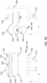
- FIG 3B the directions of flow of the coolant 450 through the conductor 200/ coolant pipe 440 are illustrated.
- the profiled form of the connector indicates the location of the recesses 345 defining the conduit 360.
- the cooling fluid is circulated through the connector and as it contacts the surfaces proximate to the conduit 360 namely an inner recessed surface 346 of the upper plate 340 and an upper surface 322 of the lower plate, heat is transferred from the connector 300 to the circulating coolant.
- the conduit 360 describes a generally u-shaped or n-shaped continuous path between the inlet 361 and the outlet 363. Referring to Figure 3B portions 360-1, 360-2 and 360-3 of the conduit 360 are shown.
- the conduit may further comprise channel portions 367 in communication with the main portion of the conduit 360, formed and located to provide circulation of fluid to and between the port 338 and receivers 337 at the electrical terminal connection portion 313.
- fluid 450 flows in through inlet 361 through portion 360-1, and portion 360-2 and then via portion 360-3 to the outlet 362.
- Figures 3C and 3D show exploded views of the connector 300, electrical terminal 550, conductor 200, bolts 551 and nuts 552 of Figures 3A and 3B .
- the outlet 362 in the lower plate 320 is visible in Figure 3C .
- the openings 221 and 222 in the conductor 200 are visible in Figures 3C and 3D .
- the bolts 551 are threaded and the connector 300 can be securely attached or fixed to the terminal 550 using the bolts 551 and nuts 552.
- the coolant 450 is circulated by a pump, the conductor 200/coolant pipe 440 are connected in a fluid circuit, and the one or more connectors 300 is also on that common fluid circuit.
- the pressure of the coolant in the fluid circuit and the pump provides for the circulation and flow of the coolant through the conduit 360 and through the coolant pipe 440.
- the arrangement of the specification provides for direct fluid cooling of the conductor 200 and further provides for direct fluid cooling of the connector clamps 300, during operation.
- an exemplary power distribution system 500 comprising the power cable assembly 100, 200, 300 and an integrated cooling system 400 is described.
- the power cable assembly 100, 200, 300 is coupled to the cooling system 400.
- the cooling system 400 of Figure 4 comprises a pump 420 and a cooling unit 430.
- the power cable assembly 100 comprising the conductor 200.
- the coolant pipe 440 comprises a coolant inlet 441 and the coolant outlet 442.
- One or more connectors 443, 444 are provided for coupling of the conductor 200 to the cooling system 400.
- the coolant preferably a dielectric coolant 450
- the coolant is circulated through the interior channel 225 of the conductor 200 of the power cable assembly, between the coolant inlet 441 and the coolant outlet 442.
- connectors 300 are provided for coupling the conductor to between electrical terminals.
- the coolant is also circulated through the connectors 300.
- the coolant is circulated through a conduit 360 of each connector 300.
- the coolant inlet 441 and coolant outlet 442 are located at opposite ends of the power cable assembly 100. It is however, appreciated that in an alternative arrangement the inlet and outlet may be located at the same end, the first end of the power cable assembly - in such an arrangement a U-bend or connector or other coolant flow return feature would be provided at the second end of the power cable assembly.
- the coolant may comprise a dielectric coolant.
- the cooling system 400 comprises a closed loop coolant circulation system.
- the coolant 450 is circulated by the pump 420 through the interior channel 225 of the electrical conductor 200 which defines the coolant pipe 440, between the inlet 441 and outlet 442 and via the cooling unit 430.
- the dielectric coolant 450 may be circulated in direct contact with the conductor 200 and with the connector 300.
- the cooling system 400 is configured for coupling to the coolant inlet 441 and the coolant outlet 442 using one or more connectors.
- the power distribution system 500 comprises an integrated cooling system 400.
- the arrangement defines an internal cooling system.
- the power cable assembly is connectable to a cooling system and operable with an integrated cooling system.
- the power distribution system and the power cable assembly are configured for connection between a power supply 510 and a battery 520.
- the first and second end contact surfaces 205 of the conductor 200 of the power cable are configured for coupling via first and second connectors 300 to a node of an electrical power supply at a first end and a battery at a second end, respectively.
- the contact surfaces 205 of the electrical conductor 200 are conducting end surfaces at the first and second ends of the power cable assembly.
- the interior channel 225 through which the coolant 450 is circulated is configured for coupling to the cooling system 400 via one or more connectors.
- the coolant inlet 441 and outlet 442 are thus coupled to the cooling unit 430 and pump 420 and to the power cable assembly.
- the power distribution system 500 in effect comprises an electrical conducting channel and a coolant flow or circulation channel, arranged in parallel.
- the dielectric coolant 450 is circulated through the conductor 200, to absorb heat therefrom by heat transfer to the dielectric coolant.
- the circulation of the dielectric coolant 200 in direct contact with the conductor advantageously avoids current leakage and provides for an improved heat transfer from the conductor to the coolant 450 and an improved cooling.
- the coolant 450 is also circulated via connectors 300 for coupling the conductor 200 to the power distribution system 500. Therefore, the advantages of cooling are also provided to the connectors.
- connectors 300 are coupled to the conductor of the power cable. While not shown in the drawings which focus on the conducting features, the arrangement is provided with an external insulation which surrounds assembly including the connectors and the conductor.
- the power cable assembly comprises a fluid coded conductor.
- the connectors 300 of arrangement of the specification provide fluid cooled clamps.
- the connector 300 with integrated cooling system allows in exemplary arrangements for operating temperature rise (temperature above ambient temperature) to be maintained in the range in an exemplary arrangement of below around 50 degrees Celsius and dependent on conductor cross section and current loads.
- Current loads in an exemplary arrangement, in the range of 100- 1000A, or even higher, may be applied.
- the electrical current load provided may be in the range of 600 to 1000 A.
- the clamp 300 and terminal connection 550 may be comprised of copper.
- the bolt 551 or other fixing may be of steel.
- the fixing being used to connect the connector or clamp to a terminal connector for supply of current to the connector and via the connector to the conductor.
- the busbar 200 or conductor 200 may be comprised of Aluminium.
- a coolant volume flow rate in the range of 1 to 2 I/minute may be provided to the coolant pipe 440.
- Any suitable coolant for example a dielectric coolant comprising a Novec 3M dielectric coolant may be used and provided at an initial temperature of 20°C.
- a clamp of the prior art may have a depth of the other of 4mm from lower surface to upper surface.
- the clamp 300 of the present specificatbn may be of similar dimensions in depth.
- the further features of the power assembly 100 of the present specification provides in addition to fluid or liquid-cooled cables, for delivery of cooling to the portions where the cables are connected to the conductor.
- the places where the cables are connected have been identified as points susceptible to overheating due to increased connection resistance.
- the connectors may be a critical point of the system due to heating.
- the provision of connectors or clamps according to the present specification provide advantages and are directed to addressing heating.
- the invention provides for a connector or clamp having a conduit for coupling to a coolant pipe system.
- the connector having two parts which are profiled to form recesses and fixed togetherto form the conduit allows for efficient use of the surfaces of the interior of the connector to dissipate heat from the clamp and to provide further protection against overheating.
- the coolant pipe and the connector both comprise features which work together to direct the flow of coolant through the clamp.
- two openings are provided in the liquid-cooled conductor wall. Vanes or flanges may be located at the opening to assist in diverting coolant to the conduit of the connector.
- the profiled clamp or connector may be formed by welding the two elements thereof namely the upper plate 340 and the lower plate 320 together.
- the connector may then be soldered to the cooling / power cable; with the opening in alignment.
- the current/cooling cable allows the coolant to flow through the clamp and the arrangement advantageously provides for a maximum use of the cooling surface and the use of welds as a contact point with the current connection
- a clamp may typically be formed of a single, profiled flat bar that is welded to the current / cooling conductor.
- the arrangement of the clamp 300 of the specification in contrast advantageously provides a two-part clamp formed for the location of an integral conduit within the clamp body to allow cooling of the clamp. The additional cooling prevents overheating of critical points such as power connections.
- the power cable assembly 100 may for example be used in applications including for the delivery of power from a power supply to provide charging of a battery of a car.
- the high voltage power cable assembly 100 may be a flexible cable.
- the power cable assembly 100 comprises a high voltage, HV, power cable.
- the power cable assembly 100 is configured for delivery of high current loads.
- the electrical conductor200 is a high voltage, HV, conductor.
- the electrical conductor 200 is comprised of a metal material.
- the metal may comprise for example: copper, copper ETP (electrolytic tough-pitch copper), or a copper alloy.
- the metal may comprise aluminium or an aluminium alloy.
- the connector may comprise copper.
- other suitable alternative materials may be used.
- the conductor 200 and the connector 300 are illustrated to show the connection of the conducting portions, it will be appreciated that the conductor and connector as provided for use one or more layers of insulation and may further comprise a shielding layer.
- the power cable assembly 100 may in an arrangement of the specification comprises: a first insulating layer surrounding the external surface 220 of the conductor 200; a shielding layer surrounding the first insulating layer; a second insulating layer external to the first shielding layer.
- the power cable assembly may comprise a first insulating layer surrounding the external surface 220 of the electrical conductor 200.
- the power cable assembly 100 may provide the connector integrally coupled to the conductor. In such an arrangement, insulation may be arranged around the conductor and connector, as described above.
- the coolant 450 has dielectric properties and accordingly is configured to be used and circulated in direct contact with the electrical conductor 200 to be cooled.
- the dielectric coolant 450 may comprise a dielectric liquid.
- the dielectric coolant is a fully dielectric liquid.
- the dielectric coolant may comprise, for example, one of the following:
- dielectric coolants are provided as examples of suitable dielectric coolants for use in the arrangement of the specification, and that other suitable coolants may also be used.
- the arrangements of the specification and claims advantageously provide improved heat exchange between the dielectric coolant and the conductor as the coolant is provided in direct contact with the heat transfer surface of the conductor.
- the improved heat exchange for cooling provides improved conductivity and further that the cross section of the conductor may be decreased in comparison with typical HV conductors, HV busbars or HV cable cross-sections.
- the arrangements of specification are advantageously configured for use and operation across a wide range of current loads for example from 100 A to 1000 A, or even higher, the form, structure and dimensions of the power cable assembly may be adjusted as required for load and to provide the required thermal response levels.
- the power cable assembly of arrangements of the specification is configured for coupling to a cooling system.
- the power cable assembly may be coupled to a cooling system.
Landscapes
- Engineering & Computer Science (AREA)
- Power Engineering (AREA)
- Transportation (AREA)
- Mechanical Engineering (AREA)
- Connector Housings Or Holding Contact Members (AREA)
Priority Applications (3)
| Application Number | Priority Date | Filing Date | Title |
|---|---|---|---|
| EP22177180.1A EP4287409A1 (de) | 2022-06-03 | 2022-06-03 | Elektrischer verbinder zur verbindung eines hochspannungsstromkabels mit einem elektrischen leiter mit einer elektrischen klemme |
| US18/204,471 US20230396003A1 (en) | 2022-06-03 | 2023-06-01 | Electrical connector for connecting high voltage power cable including electrical conductor to electrical terminal |
| CN202310657967.6A CN117175242A (zh) | 2022-06-03 | 2023-06-05 | 用于将包括电导体的高压电力电缆连接到电端子的电连接器 |
Applications Claiming Priority (1)
| Application Number | Priority Date | Filing Date | Title |
|---|---|---|---|
| EP22177180.1A EP4287409A1 (de) | 2022-06-03 | 2022-06-03 | Elektrischer verbinder zur verbindung eines hochspannungsstromkabels mit einem elektrischen leiter mit einer elektrischen klemme |
Publications (1)
| Publication Number | Publication Date |
|---|---|
| EP4287409A1 true EP4287409A1 (de) | 2023-12-06 |
Family
ID=81940655
Family Applications (1)
| Application Number | Title | Priority Date | Filing Date |
|---|---|---|---|
| EP22177180.1A Pending EP4287409A1 (de) | 2022-06-03 | 2022-06-03 | Elektrischer verbinder zur verbindung eines hochspannungsstromkabels mit einem elektrischen leiter mit einer elektrischen klemme |
Country Status (3)
| Country | Link |
|---|---|
| US (1) | US20230396003A1 (de) |
| EP (1) | EP4287409A1 (de) |
| CN (1) | CN117175242A (de) |
Citations (6)
| Publication number | Priority date | Publication date | Assignee | Title |
|---|---|---|---|---|
| US20110003517A1 (en) * | 2008-07-16 | 2011-01-06 | Masahiro Akahori | Terminal mounting structure in electrical junction box |
| EP3525296A1 (de) * | 2018-02-12 | 2019-08-14 | TE Connectivity Germany GmbH | Elektrische anschlusseinheit und batteriesystem |
| CN209282445U (zh) * | 2019-02-11 | 2019-08-20 | 洛阳正奇机械有限公司 | 一种大功率充电桩用液冷电缆电极 |
| WO2019239263A1 (en) * | 2018-06-13 | 2019-12-19 | Te Connectivity Corporation | Electrical power terminal for a charging system |
| CN210430148U (zh) * | 2019-08-02 | 2020-04-28 | 中国南方电网有限责任公司超高压输电公司曲靖局 | 一种直流输电导流接头用通流散热u形夹 |
| DE102019117649A1 (de) * | 2019-07-01 | 2021-01-07 | Phoenix Contact E-Mobility Gmbh | Aktiv gekühltes Ladesteckverbinderteil |
-
2022
- 2022-06-03 EP EP22177180.1A patent/EP4287409A1/de active Pending
-
2023
- 2023-06-01 US US18/204,471 patent/US20230396003A1/en active Pending
- 2023-06-05 CN CN202310657967.6A patent/CN117175242A/zh active Pending
Patent Citations (6)
| Publication number | Priority date | Publication date | Assignee | Title |
|---|---|---|---|---|
| US20110003517A1 (en) * | 2008-07-16 | 2011-01-06 | Masahiro Akahori | Terminal mounting structure in electrical junction box |
| EP3525296A1 (de) * | 2018-02-12 | 2019-08-14 | TE Connectivity Germany GmbH | Elektrische anschlusseinheit und batteriesystem |
| WO2019239263A1 (en) * | 2018-06-13 | 2019-12-19 | Te Connectivity Corporation | Electrical power terminal for a charging system |
| CN209282445U (zh) * | 2019-02-11 | 2019-08-20 | 洛阳正奇机械有限公司 | 一种大功率充电桩用液冷电缆电极 |
| DE102019117649A1 (de) * | 2019-07-01 | 2021-01-07 | Phoenix Contact E-Mobility Gmbh | Aktiv gekühltes Ladesteckverbinderteil |
| CN210430148U (zh) * | 2019-08-02 | 2020-04-28 | 中国南方电网有限责任公司超高压输电公司曲靖局 | 一种直流输电导流接头用通流散热u形夹 |
Also Published As
| Publication number | Publication date |
|---|---|
| US20230396003A1 (en) | 2023-12-07 |
| CN117175242A (zh) | 2023-12-05 |
Similar Documents
| Publication | Publication Date | Title |
|---|---|---|
| CN112770929B (zh) | 具有冷却管的充电系统 | |
| CN112272902B (zh) | 用于充电系统的电功率端子 | |
| WO2021013919A1 (en) | Electrical vehicle charging system for charging an electrical vehicle | |
| US11641098B1 (en) | Cooling system for busbars | |
| CN109075498A (zh) | 具有经冷却的接触元件的插式连接器部件 | |
| WO2020245687A1 (en) | Heat exchanger for a power connector | |
| CN111755864A (zh) | 用于电源连接器的电缆热交换器 | |
| US10899241B2 (en) | Connecting element and connecting apparatus for electrically connecting a cable to an electrical device of a motor vehicle | |
| US20240042876A1 (en) | Cooling module for a plug connector part, and plug connector part | |
| US11935672B2 (en) | Power cable assembly for a power distribution system having an integrated cooling system | |
| US20230034451A1 (en) | Power cable assembly for a power distribution system having an integrated cooling system | |
| US20230030269A1 (en) | Power cable assembly for a power distribution system having an integrated cooling system | |
| CN114786988A (zh) | 用于插塞连接件、即充电插头的包括冷却装置的接触组件 | |
| CN112055668A (zh) | 充电插头的保护性接地和冷却系统、用于将电能输送到电能接收器的充电插头和充电站 | |
| CN113302787A (zh) | 蓄电池模块的热管理 | |
| EP4287409A1 (de) | Elektrischer verbinder zur verbindung eines hochspannungsstromkabels mit einem elektrischen leiter mit einer elektrischen klemme | |
| EP3853920B1 (de) | Verfahren zur kühlung von batteriezellen | |
| US11923113B2 (en) | Power cable assembly for a power distribution system having an integrated cooling system | |
| CN117120294A (zh) | 用于将至少一个与插式连接器部件连接的电线冷却的冷却装置 | |
| US20230299512A1 (en) | Hybrid electric charging inlet | |
| CN116744653A (zh) | 散热结构及具有其的连接口结构 | |
| CN116092742A (zh) | 一种水冷电缆 | |
| CN111903046A (zh) | 电力转换装置 |
Legal Events
| Date | Code | Title | Description |
|---|---|---|---|
| PUAI | Public reference made under article 153(3) epc to a published international application that has entered the european phase |
Free format text: ORIGINAL CODE: 0009012 |
|
| STAA | Information on the status of an ep patent application or granted ep patent |
Free format text: STATUS: THE APPLICATION HAS BEEN PUBLISHED |
|
| AK | Designated contracting states |
Kind code of ref document: A1 Designated state(s): AL AT BE BG CH CY CZ DE DK EE ES FI FR GB GR HR HU IE IS IT LI LT LU LV MC MK MT NL NO PL PT RO RS SE SI SK SM TR |
|
| STAA | Information on the status of an ep patent application or granted ep patent |
Free format text: STATUS: REQUEST FOR EXAMINATION WAS MADE |
|
| 17P | Request for examination filed |
Effective date: 20240603 |
|
| RBV | Designated contracting states (corrected) |
Designated state(s): AL AT BE BG CH CY CZ DE DK EE ES FI FR GB GR HR HU IE IS IT LI LT LU LV MC MK MT NL NO PL PT RO RS SE SI SK SM TR |