EP4286896B1 - System und empfänger für gnss-signale - Google Patents
System und empfänger für gnss-signale Download PDFInfo
- Publication number
- EP4286896B1 EP4286896B1 EP23173209.0A EP23173209A EP4286896B1 EP 4286896 B1 EP4286896 B1 EP 4286896B1 EP 23173209 A EP23173209 A EP 23173209A EP 4286896 B1 EP4286896 B1 EP 4286896B1
- Authority
- EP
- European Patent Office
- Prior art keywords
- signals
- signal
- quadrature
- frequency
- phase
- Prior art date
- Legal status (The legal status is an assumption and is not a legal conclusion. Google has not performed a legal analysis and makes no representation as to the accuracy of the status listed.)
- Active
Links
Images


Classifications
-
- G—PHYSICS
- G01—MEASURING; TESTING
- G01S—RADIO DIRECTION-FINDING; RADIO NAVIGATION; DETERMINING DISTANCE OR VELOCITY BY USE OF RADIO WAVES; LOCATING OR PRESENCE-DETECTING BY USE OF THE REFLECTION OR RERADIATION OF RADIO WAVES; ANALOGOUS ARRANGEMENTS USING OTHER WAVES
- G01S19/00—Satellite radio beacon positioning systems; Determining position, velocity or attitude using signals transmitted by such systems
- G01S19/01—Satellite radio beacon positioning systems transmitting time-stamped messages, e.g. GPS [Global Positioning System], GLONASS [Global Orbiting Navigation Satellite System] or GALILEO
- G01S19/13—Receivers
- G01S19/33—Multimode operation in different systems which transmit time stamped messages, e.g. GPS/GLONASS
-
- G—PHYSICS
- G01—MEASURING; TESTING
- G01S—RADIO DIRECTION-FINDING; RADIO NAVIGATION; DETERMINING DISTANCE OR VELOCITY BY USE OF RADIO WAVES; LOCATING OR PRESENCE-DETECTING BY USE OF THE REFLECTION OR RERADIATION OF RADIO WAVES; ANALOGOUS ARRANGEMENTS USING OTHER WAVES
- G01S19/00—Satellite radio beacon positioning systems; Determining position, velocity or attitude using signals transmitted by such systems
- G01S19/01—Satellite radio beacon positioning systems transmitting time-stamped messages, e.g. GPS [Global Positioning System], GLONASS [Global Orbiting Navigation Satellite System] or GALILEO
- G01S19/13—Receivers
- G01S19/24—Acquisition or tracking or demodulation of signals transmitted by the system
- G01S19/243—Demodulation of navigation message
-
- G—PHYSICS
- G01—MEASURING; TESTING
- G01S—RADIO DIRECTION-FINDING; RADIO NAVIGATION; DETERMINING DISTANCE OR VELOCITY BY USE OF RADIO WAVES; LOCATING OR PRESENCE-DETECTING BY USE OF THE REFLECTION OR RERADIATION OF RADIO WAVES; ANALOGOUS ARRANGEMENTS USING OTHER WAVES
- G01S19/00—Satellite radio beacon positioning systems; Determining position, velocity or attitude using signals transmitted by such systems
- G01S19/01—Satellite radio beacon positioning systems transmitting time-stamped messages, e.g. GPS [Global Positioning System], GLONASS [Global Orbiting Navigation Satellite System] or GALILEO
- G01S19/03—Cooperating elements; Interaction or communication between different cooperating elements or between cooperating elements and receivers
- G01S19/04—Cooperating elements; Interaction or communication between different cooperating elements or between cooperating elements and receivers providing carrier phase data
-
- G—PHYSICS
- G01—MEASURING; TESTING
- G01S—RADIO DIRECTION-FINDING; RADIO NAVIGATION; DETERMINING DISTANCE OR VELOCITY BY USE OF RADIO WAVES; LOCATING OR PRESENCE-DETECTING BY USE OF THE REFLECTION OR RERADIATION OF RADIO WAVES; ANALOGOUS ARRANGEMENTS USING OTHER WAVES
- G01S19/00—Satellite radio beacon positioning systems; Determining position, velocity or attitude using signals transmitted by such systems
- G01S19/01—Satellite radio beacon positioning systems transmitting time-stamped messages, e.g. GPS [Global Positioning System], GLONASS [Global Orbiting Navigation Satellite System] or GALILEO
- G01S19/13—Receivers
- G01S19/24—Acquisition or tracking or demodulation of signals transmitted by the system
- G01S19/29—Acquisition or tracking or demodulation of signals transmitted by the system carrier including Doppler, related
-
- G—PHYSICS
- G01—MEASURING; TESTING
- G01S—RADIO DIRECTION-FINDING; RADIO NAVIGATION; DETERMINING DISTANCE OR VELOCITY BY USE OF RADIO WAVES; LOCATING OR PRESENCE-DETECTING BY USE OF THE REFLECTION OR RERADIATION OF RADIO WAVES; ANALOGOUS ARRANGEMENTS USING OTHER WAVES
- G01S19/00—Satellite radio beacon positioning systems; Determining position, velocity or attitude using signals transmitted by such systems
- G01S19/01—Satellite radio beacon positioning systems transmitting time-stamped messages, e.g. GPS [Global Positioning System], GLONASS [Global Orbiting Navigation Satellite System] or GALILEO
- G01S19/13—Receivers
- G01S19/32—Multimode operation in a single same satellite system, e.g. GPS L1/L2
-
- G—PHYSICS
- G01—MEASURING; TESTING
- G01S—RADIO DIRECTION-FINDING; RADIO NAVIGATION; DETERMINING DISTANCE OR VELOCITY BY USE OF RADIO WAVES; LOCATING OR PRESENCE-DETECTING BY USE OF THE REFLECTION OR RERADIATION OF RADIO WAVES; ANALOGOUS ARRANGEMENTS USING OTHER WAVES
- G01S19/00—Satellite radio beacon positioning systems; Determining position, velocity or attitude using signals transmitted by such systems
- G01S19/01—Satellite radio beacon positioning systems transmitting time-stamped messages, e.g. GPS [Global Positioning System], GLONASS [Global Orbiting Navigation Satellite System] or GALILEO
- G01S19/13—Receivers
- G01S19/35—Constructional details or hardware or software details of the signal processing chain
-
- G—PHYSICS
- G01—MEASURING; TESTING
- G01S—RADIO DIRECTION-FINDING; RADIO NAVIGATION; DETERMINING DISTANCE OR VELOCITY BY USE OF RADIO WAVES; LOCATING OR PRESENCE-DETECTING BY USE OF THE REFLECTION OR RERADIATION OF RADIO WAVES; ANALOGOUS ARRANGEMENTS USING OTHER WAVES
- G01S19/00—Satellite radio beacon positioning systems; Determining position, velocity or attitude using signals transmitted by such systems
- G01S19/01—Satellite radio beacon positioning systems transmitting time-stamped messages, e.g. GPS [Global Positioning System], GLONASS [Global Orbiting Navigation Satellite System] or GALILEO
- G01S19/13—Receivers
- G01S19/35—Constructional details or hardware or software details of the signal processing chain
- G01S19/37—Hardware or software details of the signal processing chain
Definitions
- a GNSS comprises a plurality of RF receivers, each RF receiver configured to operate in a different frequency band, providing a multi-band multi-constellation positioning receiver.
- receivers may be part of an integrated circuit (IC), area footprint and performance of these components are relevant figures of merit.
- IC integrated circuit
- the invention relates to a system according to the preamble of claim 1, which is known, for instance, from CN 210 351 144 U .
- Documents US 2012/026039 A1 and US 2006/176215 A1 are also of interest for the invention.
- An object of the disclosed invention is to contribute in reducing an area footprint and increasing performance of the RF receivers in GNSS systems. Such an object is achieved by means of a system having the features set forth in claim 1 that follows.
- a further object of the disclosed invention relates to a corresponding receiver, such as a GNSS receiver having the features set forth in claim 9 that follows.
- a same reference symbol may be used to designate both a node/line in a circuit and a signal which may occur at that node or line.
- a navigation receiver operates by down converting to quasi baseband the input signal received from the satellites, which is transmitted at a plurality of radio-frequency bands, using a local oscillator to step down the input frequency and allow a baseband digital management of the satellite information.
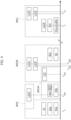
- FIG. 1 which diagrammatically shows a GNSS Global Navigation Satellite System) system (such as, for example, Global Positioning System (GPS), Global'naya Navigatsionnaya Sputnikovaya Sistema (GLONASS), Galileo System, or other types of satellite-based positioning systems
- GNSS Global Navigation Satellite System such as, for example, Global Positioning System (GPS), Global'naya Navigatsionnaya Sputnikovaya
- GLONASS Global'naya Navigatsionnaya Sputnikovaya
- Galileo System or other types of satellite-based positioning systems
- such global satellite positioning system comprises a constellation of a number N of satellites SC 1 -SC N and at least a receiving apparatus 10.
- the receiving apparatus 10 comprises an antenna RX, an analog receiving module AFE (Analog Front End), provided with a radiofrequency (RF) stage 12, and an analog-digital converter 14 (ADC), which can be implemented by hardware modules.
- AFE Analog Front End
- RF radiofrequency
- ADC analog-digital converter
- the receiving apparatus 10 may be provided with a central processing unit, memories (mass memory and/or working storage) and respective interfaces (not shown in figures), comprising a microprocessor or microcontroller, for running the software resident in it.
- the antenna RX receives a plurality of signals s 0 ,...,s N from one or more satellites SC 0 -SC N of the constellation of satellites operating in GNSS system.
- these signals can be modulated on at least one carrier signal having a carrier frequency F c .
- a system 10 for receiving and processing GNSS signals in a plurality of radiofrequency (briefly, RF) bands comprises:
- the RF front-end 12 is configured to provide a set of processed signals I1, Q 1 , I 2 , Q 2 , I 3 , Q 3 .
- the set of processed signals I 1 , Q 1 , I 2 , Q 2 , I 3 , Q 3 comprises:
- the system 10 further comprises analog-to-digital converter (briefly, ADC) circuitry 14 coupled to the front-end 12 and configured to apply analog-to-digital conversion to the set of processed signals I 1 , Q 1 , I 2 , Q 2 , I 3 , Q 3 .
- ADC analog-to-digital converter
- the ADC circuitry 14 comprises:
- the ADC circuitry 14 receives a sampling signal Fs and applies ADC conversion to the pairs of signals I 1 , Q 1 , I 2 , Q 2 , I 3 , Q 3 via sampling such signals at a frequency of the sampling signal Fs, in a manner per se known to those of skill in the art.
- the ADC circuitry 14 produces ADC converted signals S 1 , S 2 , S 3 , e.g., digital signals indicative of the contents in respective frequency bands of the RF signal S RF .
- system 10 further comprises:
- the scaling factor K of the first frequency divider 13 may have the exemplary values illustrated in Table I provided at the end of the description, which is exemplary of possible relationships between scaling factor K and local oscillator frequency, with factor of multiplication n indicating the integer multiple of the fundamental GNSS frequency.
- signals whose frequency is a multiple of the fundamental GNSS frequency f0 so as to facilitate processing of ADC converted data and of software library development.
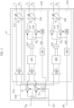
- the RF front end 12 comprises:
- the desired signal component S is superimposed on the carrier frequency FC while the image signal component IM is superimposed at a frequency twice the local oscillator minus the carrier frequency (e.g., 2*F LO1 -F C ).
- each of the processing chains is configured to generate an IF signal by processing and combining intermediate signals in phase I and in quadrature Q so as to delete the contribution of the image signal I with respect to the IF signal displaced at the IF frequency as exemplified in Figure 3C .
- the first signal processing chain CH1 comprises:
- the second signal processing chain CH2 comprises:
- the third signal processing chain CH3 comprises:
- the third filtering stage 232 is configured to filter the image signal from the second IF signal at the second intermediate frequency signal IF2, producing the signal IQ3 as a result.
- phase shifters 20, 226 and 236 exemplified in Figure 2 are purely exemplary an in no way mandatory, as in one or more embodiments the signals LO1, LO2, LO3 can be provided (e.g., by respective divider blocks) as a pair of phase-shifted signals in quadrature therebetween.
- the scaling factor G of the VCO divider 235 is an even integer number so as to provide the local oscillator to the third quadrature mixer 236, 237, 238.
- the presence of the VCO divider 235 facilitates obtaining signals I3, Q3 which have a lower intermediate frequency F IF3 with respect to the signals I, Q provided by the first quadrature mixer 20, 21, 22, e.g., I F3 ⁇ I F1 . This facilitates further processing by the A/D converter circuitry 14, for instance.
- a system 12 comprises:
- in-phase signals of the first set of in-phase signals and quadrature signals of the first set of quadrature signals have a first intermediate frequency F IF1 lower than carrier frequencies of the set of carrier frequencies of GNSS signals of the set of GNSS signals.
- the first local oscillator signal has a first local oscillator frequency that is fraction of the frequency of the VCO signal.
- the first frequency divider is configured to apply frequency division using a first programmable frequency division factor.
- the second frequency divider is configured to apply frequency division using a second programmable frequency division factor, preferably programmable in a range 18 to 20.
- GNSS signals of the set of GNSS signals transmitted from a plurality of GNSS satellites over a set of carrier frequencies comprise signals transmitted over frequency bands distinct and separate BW1, BW2, BW3A, BW3B.
- GNSS signals of the set of GNSS signals transmitted from a plurality of GNSS satellites over the set of carrier frequencies comprise at least two of:
- the first set of in-phase signals and the first set of quadrature signals comprise at least one image signal component
- the first polyphase filter is configured to filter at least one image signal component of the first set of in-phase signals and of the first set of quadrature signals, producing the first set of filtered in-phase signals and the first set of filtered quadrature signals exempt from at least one image signal component as a result.
- a (e.g., RF) receiver 100 comprises:
- the receiver comprises a baseband circuit block 16 coupled to the set of ADC circuits 14, the base stand circuit block configured to apply baseband signal processing to the set of digital signals received from the set of ADC converters.
- the set of ADC converter circuits is configured to apply the analog-to-digital conversion based on a sampling signal Fs having a sampling frequency that is a multiple of a fundamental GNSS frequency.
- the system exemplified in Figures 1 and 2 can be used to process signals which have a carrier frequency band F C that may fall in a variety of frequency bands such as, for instance:
- GNSS signals S 0 ,...,S N may be transmitted and received from satellites in a variety of known GNSS constellations using any of these frequency bands BW1, BW2, BW3A, BW4A.
- the first signal processing chain CH1 may be suitable to process a RF signal received in the first frequency band BW1, e.g., from a first set of GNSS constellation of satellites L1CA, E1, L1C, B1C, B1I, LOF1, L1OC and/or any other signal in these frequency bands.
- the second signal processing chain CH2 may be suitable to process a RF signal received in the second frequency band BW2, e.g., from a second set of constellations L5, B2a, E5a.
- the third signal processing chain CH3 may be suitable to process a RF signal S RF received in the third frequency band BW3A (e.g., from a third set of constellations L2C, B2b, B2l, E5b, L3OC) or in the fourth frequency band BW3B (e.g., from a fourth set of constellations L2OC, L2OF, B3l, E6).
- a RF signal S RF received in the third frequency band BW3A (e.g., from a third set of constellations L2C, B2b, B2l, E5b, L3OC) or in the fourth frequency band BW3B (e.g., from a fourth set of constellations L2OC, L2OF, B3l, E6).
- Table II provided at the end of the description exemplifies settings of the first signal processing chain CH1, such as carrier frequency Fc, bandwidth BW, VCO signal frequency F VCO , first local oscillator signal frequency F LO1 and intermediate frequency IF1 which may be used to process signals from a variety of constellations configured to transmit signals over frequency bands (e.g., L1c/a, L1C, E1, B1I, B1C, LOF1) in the first bandwidth BW1.
- frequency bands e.g., L1c/a, L1C, E1, B1I, B1C, LOF1
- Table III provided at the end of the description exemplifies settings of the second signal processing chain CH2, such as carrier frequency Fc, bandwidth BW, VCO signal frequency F VCO , first local oscillator signal frequency F LO1 , second LO signal frequency F LO2 , scaling factor M, intermediate frequency IF2 and maximum frequency Max F which may be used to process signals from a variety of the constellations configured to transmit signals over frequency bands (e.g., L5, such as GPS and others, B2a, E5a) in the second bandwidth BW2.
- frequency bands e.g., L5, such as GPS and others, B2a, E5a
- Table IV provided at the end of the description exemplifies settings of the third signal processing chain CH3, such as carrier frequency Fc, bandwidth BW, VCO signal frequency F VCO , first local oscillator signal frequency F LO1 , third local oscillator signal frequency F LO3 , scaling factor G, third intermediate frequency IF3 and maximum frequency Max F which may be used to process signals from a variety of constellations configured to transmit over frequency bands (e.g., L2C, B2b, B2l, E5b) in the third bandwidth BW3A.
- frequency bands e.g., L2C, B2b, B2l, E5b
- Table V provided at the end of the description exemplifies of the third signal processing chain CH3 such as carrier frequency F C , bandwidth BW, VCO signal frequency F VCO , first local oscillator signal frequency F LO1 , third local oscillator signal frequency F LO3 , scaling factor G, third intermediate frequency IF3 and maximum frequency Max F which may be used to process signals from a variety of constellations configured to transmit over frequency bands (e.g., alternative constellations L2OC, L2OF, B3l, E6) in the fourth bandwidth BW3B.
- Table VI provided at the end of the description is exemplary of combinations of constellations and respective names of channels that may be used to process signals received from such exemplary combinations of constellations.
Landscapes
- Engineering & Computer Science (AREA)
- Radar, Positioning & Navigation (AREA)
- Remote Sensing (AREA)
- Computer Networks & Wireless Communication (AREA)
- Physics & Mathematics (AREA)
- General Physics & Mathematics (AREA)
- Signal Processing (AREA)
- Superheterodyne Receivers (AREA)
Claims (11)
- System (10), umfassend:einen Eingangsknoten (SRF), der so konfiguriert ist, dass er einen Satz Signale (S0, SN) eines globalen Navigationssatellitensystems, GNSS, empfängt, die von einer Vielzahl von GNSS-Satelliten (SC0, SCN) über einen Satz Trägerfrequenzen (f1, f11, f2, f3A1, f3A2, f3B1, f3B2, Fc) übertragen werden;eine Phasenregelschleife, PLL (11), die so konfiguriert ist, dass sie ein erstes lokales Oszillatorsignal (LO1) und ein spannungsgesteuertes Oszillator-, VCO-, Signal (VO) bereitstellt;einen ersten Quadraturdemodulator (CH0), der mit dem Eingangsknoten (SRF) und mit der PLL (11) gekoppelt ist, wobei der erste Quadraturdemodulator (CH0) so konfiguriert ist, dass er Quadraturdemodulationsverarbeitung (20, 21, 22) auf den Satz GNSS-Signale (S0, SN) auf Basis des von der PLL (11) empfangenen lokalen Oszillatorsignals (LO1) anwendet, wobei der erste Quadraturdemodulator (CH0) einen ersten Satz gleichphasiger Signale (I) und einen ersten Satz Quadratursignale (Q) als Ergebnis bereitstellt,wobei gleichphasige Signale des ersten Satzes gleichphasiger Signale (I) und Quadratursignale des ersten Satzes Quadratursignale (Q) eine erste Zwischenfrequenz (FIF1) aufweisen, die niedriger ist als Trägerfrequenzen des Satzes Trägerfrequenzen (f1, f11, f2, f3A1, f3A2, f3B1, f3B2, FC) von GNSS-Signalen des Satzes GNSS-Signale (S0, SN),dadurch gekennzeichnet, dass das System (10) umfasst:eine erste Signalverarbeitungskette (CH1), die mit dem ersten Quadraturdemodulator (CH0) gekoppelt ist, um den Satz gleichphasiger Signale (I) und den Satz Quadratursignale (Q) zu empfangen, wobei die erste Signalverarbeitungskette (CH1) einen ersten Verstärker mit variabler Verstärkung, VGA, (212) umfasst, der mit dem ersten Quadraturdemodulator (CH0) gekoppelt ist, wobei der VGA (212) so konfiguriert ist, dass er eine erste Verstärkung mit variabler Verstärkung auf den ersten Satz gleichphasiger Signale (I) und auf den ersten Satz Quadratursignale (Q) anwendet, wodurch eine erste gleichphasige Signalkomponente (I1) und eine erste Quadratursignalkomponente (Q1) als Ergebnis bereitgestellt werden;eine zweite Signalverarbeitungskette (CH2), die mit dem ersten Quadraturdemodulator (CH0) gekoppelt ist, um den ersten Satz gleichphasiger Signale (I) und den ersten Satz Quadratursignale (Q) zu empfangen, und mit der PLL (11) gekoppelt ist, um das erste lokale Oszillatorsignal (LO1) zu empfangen, wobei die zweite Signalverarbeitungskette (CH2) umfasst:ein erstes Polyphasenfilter (222), das so konfiguriert ist, dass es Polyphasenfilterung auf den ersten Satz gleichphasiger Signale (I) und auf den ersten Satz Quadratursignale (Q) anwendet, wodurch ein erster Satz gefilterter gleichphasiger Signale und ein erster Satz gefilterter Quadratursignale als Ergebnis erzeugt werden;einen ersten Addierer (224), der mit dem ersten Polyphasenfilter (222) gekoppelt ist, um den ersten Satz gefilterter gleichphasiger Signale und den ersten Satz gefilterter Quadratursignale zu empfangen, wobei der erste Addierer (224) so konfiguriert ist, dass er ein erstes Summensignal (IQ2) als Summe des ersten Satzes gefilterter gleichphasiger Signale und des ersten Satzes gefilterter Quadratursignale bereitstellt,einen ersten Frequenzteiler (225), der so konfiguriert ist, dass er Frequenzteilung auf das erste lokale Oszillatorsignal (LO1) anwendet, wodurch ein zweites lokales Oszillatorsignal (LO2) als Ergebnis erzeugt wird, wobei das zweite lokale Oszillatorsignal (LO2) eine zweite lokale Oszillatorfrequenz aufweist, die ein Bruchteil der Frequenz des lokalen Oszillatorsignals (LO1) ist;einen zweiten Quadraturdemodulator (226, 227, 228), der mit dem ersten Addierer (224) und mit dem ersten Frequenzteiler (225) gekoppelt ist, wobei der zweite Quadraturdemodulator (226, 227, 228) so konfiguriert ist, dass er zweite Quadraturdemodulationsverarbeitung auf das erste Summensignal (IQ2) anwendet, wodurch auf Basis des zweiten lokalen Oszillatorsignals (LO2) ein zweiter Satz gleichphasiger Signale und ein zweiter Satz Quadratursignale bereitgestellt werden, wobei der zweite Satz gleichphasiger Signale und der zweite Satz Quadratursignale eine zweite Zwischenfrequenz (IF2) aufweisen, die niedriger ist als die erste Zwischenfrequenz (IF1, FIF1), undeinen zweiten VGA (229), der so konfiguriert ist, dass er eine zweite Verstärkung mit variabler Verstärkung auf den zweiten Satz gleichphasiger Signale und auf den zweiten Satz Quadratursignale anwendet, wobei der zweite VGA (229) so konfiguriert ist, dass er eine zweite gleichphasige Signalkomponente (I2) und eine zweite Quadratursignalkomponente (Q2) als Ergebnis erzeugt;eine dritte Signalverarbeitungskette (CH3), die mit dem ersten Quadraturdemodulator (CH0) gekoppelt ist, um den Satz gleichphasiger Signale (I) und den Satz Quadratursignale (Q) zu empfangen, und mit der PLL (11) gekoppelt ist, um das VCO-Signal (VO) zu empfangen, wobei die dritte Signalverarbeitungskette (CH3) umfasst:ein zweites Polyphasenfilter (232), das so konfiguriert ist, dass es zweite Polyphasenfilterung auf den ersten Satz gleichphasiger Signale (I) und auf den ersten Satz Quadratursignale (Q) anwendet, wodurch ein zweiter Satz gefilterter gleichphasiger Signale und ein zweiter Satz gefilterter Quadratursignale als Ergebnis erzeugt werden;einen zweiten Addierer (234), der mit dem zweiten Polyphasenfilter (232) gekoppelt ist, um den zweiten Satz gefilterter gleichphasiger Signale und den zweiten Satz gefilterter Quadratursignale von diesem zu empfangen, wobei der zweite Addierer (234) so konfiguriert ist, dass er ein zweites Summensignal (IQ3) als Summe des zweiten Satzes gefilterter gleichphasiger Signale und des zweiten Satzes gefilterter Quadratursignale bereitstellt;einen zweiten Frequenzteiler (235), der so konfiguriert ist, dass er eine zweite Frequenzteilung auf das VCO-Signal (VO) anwendet, wodurch ein drittes lokales Oszillatorsignal (LO3) als Ergebnis erzeugt wird, wobei das dritte lokale Oszillatorsignal (LO3) eine dritte lokale Oszillatorfrequenz aufweist, die ein Bruchteil der Frequenz des VCO-Signals (VO) ist;einen dritten Quadraturdemodulator (236, 237, 238), der mit dem zweiten Addierer (234) und mit dem zweiten Frequenzteiler (235) gekoppelt ist, wobei der dritte Quadraturdemodulator (236, 237, 238) so konfiguriert ist, dass er dritte Quadraturdemodulationsverarbeitung auf das zweite Summensignal (IQ3) anwendet, wodurch auf Basis des dritten lokalen Oszillatorsignals (LO3) ein dritter Satz gleichphasiger Signale und ein dritter Satz Quadratursignale bereitgestellt werden, wobei der dritte Satz gleichphasiger Signale und der dritte Satz Quadratursignale eine dritte Zwischenfrequenz (IF3) aufweisen, die niedriger ist als die zweite Zwischenfrequenz (IF2), undeinen dritten VGA (239), der so konfiguriert ist, dass er eine dritte Verstärkung mit variabler Verstärkung auf den dritten Satz gleichphasiger Signale und auf den dritten Satz Quadratursignale anwendet, wobei der dritte VGA (239) so konfiguriert ist, dass er eine dritte gleichphasige Signalkomponente (I3) und eine dritte Quadratursignalkomponente (Q3) als Ergebnis erzeugt.
- System (10) nach Anspruch 1, wobei das erste lokale Oszillatorsignal (LO1) eine erste lokale Oszillatorfrequenz aufweist, die ein Bruchteil der Frequenz des VCO-Signals (VO) ist.
- System (10) nach Anspruch 1 oder Anspruch 2, wobei der erste Frequenzteiler (225) so konfiguriert ist, dass er Frequenzteilung unter Verwendung eines ersten programmierbaren Frequenzteilungsfaktors anwendet.
- System nach einem der vorstehenden Ansprüche, wobei der zweite Frequenzteiler (235) so konfiguriert ist, dass er Frequenzteilung unter Verwendung eines zweiten programmierbaren Frequenzteilungsfaktors, der in einem Bereich von 18 bis 20 programmiert werden kann, anwendet.
- System (10) nach einem der vorstehenden Ansprüche, wobei GNSS-Signale des Satzes GNSS-Signale (S0, SN), die von einer Vielzahl von GNSS-Satelliten (SC0, SCN) über einen Satz Trägerfrequenzen (f1, f11, f2, f3A1, f3A2, f3B1, f3B2, FC) übertragen werden, Signale umfassen, die über unterschiedliche und getrennte Frequenzbänder (BW1, BW2, BW3A, BW3B) übertragen werden.
- System (10) nach einem der vorstehenden Ansprüche, wobei GNSS-Signale des Satzes GNSS-Signale (S0, SN), die von einer Vielzahl von GNSS-Satelliten (SC0, SCN) über den Satz Trägerfrequenzen (f1, f11, f2, f3A1, f3A2, f3B1, f3B2, FC) übertragen werden, mindestens zwei umfassen von:einem ersten GNSS-Signal (S0), das über eine erste Trägerfrequenz (f1, f11) übertragen wird,einem zweiten GNSS-Signal (SN), das über eine zweite Trägerfrequenz (f2) übertragen wird, wobei die zweite Trägerfrequenz (f2) höher ist als die erste Trägerfrequenz, einem dritten GNSS-Signal (SRF), das über eine dritte Trägerfrequenz (f3A1, f3A2, f3B1, f3B2) übertragen wird, die höher ist als die zweite Trägerfrequenz (f2).
- System (10) nach einem der vorstehenden Ansprüche, wobei:der erste Satz gleichphasiger Signale (I) und der erste Satz Quadratursignale (Q) mindestens eine Bildsignalkomponente umfassen, unddas erste Polyphasenfilter (222) so konfiguriert ist, dass es die mindestens eine Bildsignalkomponente des ersten Satzes gleichphasiger Signale (I) und des ersten Satzes Quadratursignale (Q) filtert, wodurch der erste Satz gefilterter gleichphasiger Signale und der erste Satz gefilterter Quadratursignale erzeugt werden, die als Ergebnis von mindestens einer Bildsignalkomponente befreit sind.
- System (10) nach einem der vorstehenden Ansprüche, wobei:der erste Satz gleichphasiger Signale (I) und der erste Satz Quadratursignale (Q) mindestens eine Bildsignalkomponente umfassen, unddas zweite Polyphasenfilter (232) so konfiguriert ist, dass es mindestens eine Bildsignalkomponente des ersten Satzes gleichphasiger Signale (I) und des ersten Satzes Quadratursignale (Q) filtert, wodurch der zweite Satz gefilterter gleichphasiger Signale und der zweite Satz gefilterter Quadratursignale erzeugt werden, die als Ergebnis von mindestens einer Bildsignalkomponente befreit sind.
- Empfänger (100), umfassend:ein System (10) nach einem der vorstehenden Ansprüche,eine Antenne (RX), die so konfiguriert ist, dass sie den Satz GNSS-Signale (S0, SN) empfängt, und die mit dem Eingangsknoten (SRF) des Systems (10) gekoppelt ist, um diesem den empfangenen Satz GNSS-Signale bereitzustellen, einen Satz Analog-Digital-Wandler-, ADC-, Schaltungen (14), die mit der ersten Signalverarbeitungskette (CH1), der zweiten Signalverarbeitungskette (CH2) und mit der dritten Signalverarbeitungskette (CH3) gekoppelt sind, wobei der Satz ADC-Schaltungen (14) so konfiguriert ist, dass er Analog-Digital-Wandlung auf die erste gleichphasige Komponente (I1), die erste Quadraturkomponente (Q1), die zweite gleichphasige Komponente (I2), die zweite Quadraturkomponente (Q2), die dritte gleichphasige Komponente (I3) und die dritte Quadraturkomponente (Q3) anwendet, wodurch ein Satz digitaler Signalkomponenten als Ergebnis bereitgestellt wird.
- Empfänger (100) nach Anspruch 9, der einen Basisband-Schaltungsblock (16) umfasst, der mit dem Satz ADC-Schaltungen (14) gekoppelt ist, wobei der Basisband-Schaltungsblock (16) so konfiguriert ist, dass er Basisband-Signalverarbeitung auf den Satz digitaler Signale, die von dem Satz ADC-Wandler (14) empfangen werden, anwendet.
- Empfänger (100) nach Anspruch 9 oder Anspruch 10, wobei der Satz ADC-Wandlerschaltungen (14) so konfiguriert ist, dass er die Analog-Digital-Wandlung auf Basis eines Abtastsignals (FS), das eine Abtastfrequenz aufweist, die ein Vielfaches einer GNSS-Grundfrequenz ist, anwendet.
Applications Claiming Priority (1)
| Application Number | Priority Date | Filing Date | Title |
|---|---|---|---|
| IT102022000011330A IT202200011330A1 (it) | 2022-05-30 | 2022-05-30 | Sistema e ricevitore per segnali gnss |
Publications (2)
| Publication Number | Publication Date |
|---|---|
| EP4286896A1 EP4286896A1 (de) | 2023-12-06 |
| EP4286896B1 true EP4286896B1 (de) | 2024-12-11 |
Family
ID=82694183
Family Applications (1)
| Application Number | Title | Priority Date | Filing Date |
|---|---|---|---|
| EP23173209.0A Active EP4286896B1 (de) | 2022-05-30 | 2023-05-12 | System und empfänger für gnss-signale |
Country Status (4)
| Country | Link |
|---|---|
| US (1) | US12216213B2 (de) |
| EP (1) | EP4286896B1 (de) |
| CN (1) | CN117148395A (de) |
| IT (1) | IT202200011330A1 (de) |
Family Cites Families (8)
| Publication number | Priority date | Publication date | Assignee | Title |
|---|---|---|---|---|
| JP2002368642A (ja) * | 2001-06-08 | 2002-12-20 | Sony Corp | 受信機およびic |
| US7551127B2 (en) * | 2005-02-10 | 2009-06-23 | Motorola, Inc. | Reconfigurable downconverter for a multi-band positioning receiver |
| DE602005018492D1 (de) * | 2005-11-03 | 2010-02-04 | Qualcomm Inc | Mehrbandempfänger für Signale von Navigationssatelliten (GNSS) |
| DE102008026698A1 (de) * | 2008-06-04 | 2009-12-17 | Fraunhofer-Gesellschaft zur Förderung der angewandten Forschung e.V. | Mehrfrequenzband-Empfänger |
| US8427366B2 (en) * | 2010-07-27 | 2013-04-23 | Texas Instruments Incorporated | Dual frequency receiver with single I/Q IF pair and mixer |
| US20130187810A1 (en) * | 2011-10-28 | 2013-07-25 | Maxime Leclercq | Method And System For An Embedded And Hosted Architecture For A Medium Earth Orbit Satellite And Low Earth Orbit Satellite Positioning Engine |
| EP3648517A4 (de) * | 2017-06-30 | 2020-07-08 | Sony Semiconductor Solutions Corporation | Drahtloses endgerät, informationsverarbeitungsvorrichtung, informationsverarbeitungsverfahren und programm |
| CN210351144U (zh) * | 2019-11-22 | 2020-04-17 | 成都旋极星源信息技术有限公司 | 多模多频段三通道射频接收机 |
-
2022
- 2022-05-30 IT IT102022000011330A patent/IT202200011330A1/it unknown
-
2023
- 2023-05-04 US US18/312,157 patent/US12216213B2/en active Active
- 2023-05-12 EP EP23173209.0A patent/EP4286896B1/de active Active
- 2023-05-29 CN CN202310616854.1A patent/CN117148395A/zh active Pending
Also Published As
| Publication number | Publication date |
|---|---|
| EP4286896A1 (de) | 2023-12-06 |
| US12216213B2 (en) | 2025-02-04 |
| IT202200011330A1 (it) | 2023-11-30 |
| CN117148395A (zh) | 2023-12-01 |
| US20230384459A1 (en) | 2023-11-30 |
Similar Documents
| Publication | Publication Date | Title |
|---|---|---|
| US8604974B2 (en) | Glonass/GPS de-rotation and filtering with ADC sampling at 60-80 MSPS | |
| EP1671417B1 (de) | Empfänger mit einer oszillationsschaltung zur erzeugung eines bildzurückweisungs-kalibrationstons | |
| US9482760B2 (en) | Receiver for simultaneous reception of signals from multiple GNSS satellite systems | |
| US10101461B2 (en) | Radio frequency circuit structure for implementing function of converting GNSS satellite signal into baseband signal | |
| US6856794B1 (en) | Monolithic GPS RF front end integrated circuit | |
| US8306154B2 (en) | Multi-frequency band receiver | |
| CN101123440B (zh) | 多射频频带的直接射频数字化方法及其接收器 | |
| WO2008144990A1 (en) | A general configurable rf processing method and system for navigation satellite signal | |
| JP2003509909A (ja) | 角度変調rf信号に対する位相補間受信機 | |
| CN101174840B (zh) | 多组频带的可程控直接射频数字化接收器及其方法 | |
| CN102243308A (zh) | 一种单通道射频接收机及其频率规划方法 | |
| CN104237910A (zh) | 多通道导航射频接收机 | |
| CN107942355A (zh) | 一种四模三通道并行gnss 射频接收机 | |
| CN202182942U (zh) | 一种低功耗的全球导航系统双通道射频接收机 | |
| US6356747B1 (en) | Intermediary low-frequency frequency-conversion radiofrequency reception | |
| US7047023B1 (en) | GPS RF front end IC with frequency plan for improved integrability | |
| CN113037307B (zh) | 卫星接收机芯片和卫星接收机系统 | |
| US20150276935A1 (en) | Method And System For Repurposing Of A Global Navigation Satellite System Receiver For Receiving Low-Earth Orbit Communication Satellite Signals | |
| CN110244327A (zh) | 一种卫星定位接收机及其射频前端 | |
| EP4286896A1 (de) | System und empfänger für gnss-signale | |
| US20160025861A1 (en) | Method and system for indoor global navigation satellite system detection utilizing low-earth orbit satellite signals | |
| CN111988050B (zh) | 基于射频直接采样的soc芯片采样率选择方法及装置 | |
| RU2097919C1 (ru) | Свч-приемник сигналов спутниковых радионавигационных систем | |
| RU2124214C1 (ru) | Устройство для приема сигналов спутниковых радионавигационных систем | |
| US7336717B2 (en) | Receiver circuit, in particular for a mobile radio |
Legal Events
| Date | Code | Title | Description |
|---|---|---|---|
| PUAI | Public reference made under article 153(3) epc to a published international application that has entered the european phase |
Free format text: ORIGINAL CODE: 0009012 |
|
| STAA | Information on the status of an ep patent application or granted ep patent |
Free format text: STATUS: THE APPLICATION HAS BEEN PUBLISHED |
|
| AK | Designated contracting states |
Kind code of ref document: A1 Designated state(s): AL AT BE BG CH CY CZ DE DK EE ES FI FR GB GR HR HU IE IS IT LI LT LU LV MC ME MK MT NL NO PL PT RO RS SE SI SK SM TR |
|
| STAA | Information on the status of an ep patent application or granted ep patent |
Free format text: STATUS: REQUEST FOR EXAMINATION WAS MADE |
|
| 17P | Request for examination filed |
Effective date: 20240429 |
|
| RBV | Designated contracting states (corrected) |
Designated state(s): AL AT BE BG CH CY CZ DE DK EE ES FI FR GB GR HR HU IE IS IT LI LT LU LV MC ME MK MT NL NO PL PT RO RS SE SI SK SM TR |
|
| GRAP | Despatch of communication of intention to grant a patent |
Free format text: ORIGINAL CODE: EPIDOSNIGR1 |
|
| STAA | Information on the status of an ep patent application or granted ep patent |
Free format text: STATUS: GRANT OF PATENT IS INTENDED |
|
| RIC1 | Information provided on ipc code assigned before grant |
Ipc: G01S 19/37 20100101ALI20240712BHEP Ipc: G01S 19/35 20100101ALI20240712BHEP Ipc: G01S 19/32 20100101ALI20240712BHEP Ipc: G01S 19/33 20100101ALI20240712BHEP Ipc: G01S 19/29 20100101AFI20240712BHEP |
|
| INTG | Intention to grant announced |
Effective date: 20240806 |
|
| GRAS | Grant fee paid |
Free format text: ORIGINAL CODE: EPIDOSNIGR3 |
|
| GRAA | (expected) grant |
Free format text: ORIGINAL CODE: 0009210 |
|
| STAA | Information on the status of an ep patent application or granted ep patent |
Free format text: STATUS: THE PATENT HAS BEEN GRANTED |
|
| AK | Designated contracting states |
Kind code of ref document: B1 Designated state(s): AL AT BE BG CH CY CZ DE DK EE ES FI FR GB GR HR HU IE IS IT LI LT LU LV MC ME MK MT NL NO PL PT RO RS SE SI SK SM TR |
|
| REG | Reference to a national code |
Ref country code: GB Ref legal event code: FG4D |
|
| REG | Reference to a national code |
Ref country code: CH Ref legal event code: EP |
|
| REG | Reference to a national code |
Ref country code: DE Ref legal event code: R096 Ref document number: 602023001313 Country of ref document: DE |
|
| REG | Reference to a national code |
Ref country code: IE Ref legal event code: FG4D |
|
| REG | Reference to a national code |
Ref country code: LT Ref legal event code: MG9D |
|
| PG25 | Lapsed in a contracting state [announced via postgrant information from national office to epo] |
Ref country code: HR Free format text: LAPSE BECAUSE OF FAILURE TO SUBMIT A TRANSLATION OF THE DESCRIPTION OR TO PAY THE FEE WITHIN THE PRESCRIBED TIME-LIMIT Effective date: 20241211 |
|
| PG25 | Lapsed in a contracting state [announced via postgrant information from national office to epo] |
Ref country code: FI Free format text: LAPSE BECAUSE OF FAILURE TO SUBMIT A TRANSLATION OF THE DESCRIPTION OR TO PAY THE FEE WITHIN THE PRESCRIBED TIME-LIMIT Effective date: 20241211 |
|
| PG25 | Lapsed in a contracting state [announced via postgrant information from national office to epo] |
Ref country code: BG Free format text: LAPSE BECAUSE OF FAILURE TO SUBMIT A TRANSLATION OF THE DESCRIPTION OR TO PAY THE FEE WITHIN THE PRESCRIBED TIME-LIMIT Effective date: 20241211 |
|
| REG | Reference to a national code |
Ref country code: NL Ref legal event code: MP Effective date: 20241211 |
|
| PG25 | Lapsed in a contracting state [announced via postgrant information from national office to epo] |
Ref country code: ES Free format text: LAPSE BECAUSE OF FAILURE TO SUBMIT A TRANSLATION OF THE DESCRIPTION OR TO PAY THE FEE WITHIN THE PRESCRIBED TIME-LIMIT Effective date: 20241211 |
|
| PG25 | Lapsed in a contracting state [announced via postgrant information from national office to epo] |
Ref country code: NO Free format text: LAPSE BECAUSE OF FAILURE TO SUBMIT A TRANSLATION OF THE DESCRIPTION OR TO PAY THE FEE WITHIN THE PRESCRIBED TIME-LIMIT Effective date: 20250311 |
|
| PG25 | Lapsed in a contracting state [announced via postgrant information from national office to epo] |
Ref country code: LV Free format text: LAPSE BECAUSE OF FAILURE TO SUBMIT A TRANSLATION OF THE DESCRIPTION OR TO PAY THE FEE WITHIN THE PRESCRIBED TIME-LIMIT Effective date: 20241211 Ref country code: GR Free format text: LAPSE BECAUSE OF FAILURE TO SUBMIT A TRANSLATION OF THE DESCRIPTION OR TO PAY THE FEE WITHIN THE PRESCRIBED TIME-LIMIT Effective date: 20250312 |
|
| PG25 | Lapsed in a contracting state [announced via postgrant information from national office to epo] |
Ref country code: RS Free format text: LAPSE BECAUSE OF FAILURE TO SUBMIT A TRANSLATION OF THE DESCRIPTION OR TO PAY THE FEE WITHIN THE PRESCRIBED TIME-LIMIT Effective date: 20250311 |
|
| PG25 | Lapsed in a contracting state [announced via postgrant information from national office to epo] |
Ref country code: NL Free format text: LAPSE BECAUSE OF FAILURE TO SUBMIT A TRANSLATION OF THE DESCRIPTION OR TO PAY THE FEE WITHIN THE PRESCRIBED TIME-LIMIT Effective date: 20241211 |
|
| REG | Reference to a national code |
Ref country code: AT Ref legal event code: MK05 Ref document number: 1750823 Country of ref document: AT Kind code of ref document: T Effective date: 20241211 |
|
| PG25 | Lapsed in a contracting state [announced via postgrant information from national office to epo] |
Ref country code: SM Free format text: LAPSE BECAUSE OF FAILURE TO SUBMIT A TRANSLATION OF THE DESCRIPTION OR TO PAY THE FEE WITHIN THE PRESCRIBED TIME-LIMIT Effective date: 20241211 |
|
| PG25 | Lapsed in a contracting state [announced via postgrant information from national office to epo] |
Ref country code: PL Free format text: LAPSE BECAUSE OF FAILURE TO SUBMIT A TRANSLATION OF THE DESCRIPTION OR TO PAY THE FEE WITHIN THE PRESCRIBED TIME-LIMIT Effective date: 20241211 |
|
| PGFP | Annual fee paid to national office [announced via postgrant information from national office to epo] |
Ref country code: DE Payment date: 20250423 Year of fee payment: 3 |
|
| PG25 | Lapsed in a contracting state [announced via postgrant information from national office to epo] |
Ref country code: IS Free format text: LAPSE BECAUSE OF FAILURE TO SUBMIT A TRANSLATION OF THE DESCRIPTION OR TO PAY THE FEE WITHIN THE PRESCRIBED TIME-LIMIT Effective date: 20250411 |
|
| PG25 | Lapsed in a contracting state [announced via postgrant information from national office to epo] |
Ref country code: PT Free format text: LAPSE BECAUSE OF FAILURE TO SUBMIT A TRANSLATION OF THE DESCRIPTION OR TO PAY THE FEE WITHIN THE PRESCRIBED TIME-LIMIT Effective date: 20250411 |
|
| PG25 | Lapsed in a contracting state [announced via postgrant information from national office to epo] |
Ref country code: EE Free format text: LAPSE BECAUSE OF FAILURE TO SUBMIT A TRANSLATION OF THE DESCRIPTION OR TO PAY THE FEE WITHIN THE PRESCRIBED TIME-LIMIT Effective date: 20241211 |
|
| PG25 | Lapsed in a contracting state [announced via postgrant information from national office to epo] |
Ref country code: RO Free format text: LAPSE BECAUSE OF FAILURE TO SUBMIT A TRANSLATION OF THE DESCRIPTION OR TO PAY THE FEE WITHIN THE PRESCRIBED TIME-LIMIT Effective date: 20241211 Ref country code: AT Free format text: LAPSE BECAUSE OF FAILURE TO SUBMIT A TRANSLATION OF THE DESCRIPTION OR TO PAY THE FEE WITHIN THE PRESCRIBED TIME-LIMIT Effective date: 20241211 |
|
| PG25 | Lapsed in a contracting state [announced via postgrant information from national office to epo] |
Ref country code: SK Free format text: LAPSE BECAUSE OF FAILURE TO SUBMIT A TRANSLATION OF THE DESCRIPTION OR TO PAY THE FEE WITHIN THE PRESCRIBED TIME-LIMIT Effective date: 20241211 |
|
| PG25 | Lapsed in a contracting state [announced via postgrant information from national office to epo] |
Ref country code: CZ Free format text: LAPSE BECAUSE OF FAILURE TO SUBMIT A TRANSLATION OF THE DESCRIPTION OR TO PAY THE FEE WITHIN THE PRESCRIBED TIME-LIMIT Effective date: 20241211 |
|
| PG25 | Lapsed in a contracting state [announced via postgrant information from national office to epo] |
Ref country code: IT Free format text: LAPSE BECAUSE OF FAILURE TO SUBMIT A TRANSLATION OF THE DESCRIPTION OR TO PAY THE FEE WITHIN THE PRESCRIBED TIME-LIMIT Effective date: 20241211 |
|
| PG25 | Lapsed in a contracting state [announced via postgrant information from national office to epo] |
Ref country code: SE Free format text: LAPSE BECAUSE OF FAILURE TO SUBMIT A TRANSLATION OF THE DESCRIPTION OR TO PAY THE FEE WITHIN THE PRESCRIBED TIME-LIMIT Effective date: 20241211 |
|
| REG | Reference to a national code |
Ref country code: DE Ref legal event code: R097 Ref document number: 602023001313 Country of ref document: DE |
|
| PG25 | Lapsed in a contracting state [announced via postgrant information from national office to epo] |
Ref country code: DK Free format text: LAPSE BECAUSE OF FAILURE TO SUBMIT A TRANSLATION OF THE DESCRIPTION OR TO PAY THE FEE WITHIN THE PRESCRIBED TIME-LIMIT Effective date: 20241211 |
|
| PLBE | No opposition filed within time limit |
Free format text: ORIGINAL CODE: 0009261 |
|
| STAA | Information on the status of an ep patent application or granted ep patent |
Free format text: STATUS: NO OPPOSITION FILED WITHIN TIME LIMIT |
|
| 26N | No opposition filed |
Effective date: 20250912 |
|
| PG25 | Lapsed in a contracting state [announced via postgrant information from national office to epo] |
Ref country code: LU Free format text: LAPSE BECAUSE OF NON-PAYMENT OF DUE FEES Effective date: 20250512 |
|
| REG | Reference to a national code |
Ref country code: BE Ref legal event code: MM Effective date: 20250531 |
|
| PG25 | Lapsed in a contracting state [announced via postgrant information from national office to epo] |
Ref country code: MC Free format text: LAPSE BECAUSE OF FAILURE TO SUBMIT A TRANSLATION OF THE DESCRIPTION OR TO PAY THE FEE WITHIN THE PRESCRIBED TIME-LIMIT Effective date: 20241211 |
|
| PG25 | Lapsed in a contracting state [announced via postgrant information from national office to epo] |
Ref country code: IE Free format text: LAPSE BECAUSE OF NON-PAYMENT OF DUE FEES Effective date: 20250512 |
|
| PG25 | Lapsed in a contracting state [announced via postgrant information from national office to epo] |
Ref country code: BE Free format text: LAPSE BECAUSE OF NON-PAYMENT OF DUE FEES Effective date: 20250531 |
|
| PG25 | Lapsed in a contracting state [announced via postgrant information from national office to epo] |
Ref country code: FR Free format text: LAPSE BECAUSE OF NON-PAYMENT OF DUE FEES Effective date: 20250531 |