EP4286243A1 - Validation of a sensor unit of a rail vehicle for object localization - Google Patents
Validation of a sensor unit of a rail vehicle for object localization Download PDFInfo
- Publication number
- EP4286243A1 EP4286243A1 EP23157523.4A EP23157523A EP4286243A1 EP 4286243 A1 EP4286243 A1 EP 4286243A1 EP 23157523 A EP23157523 A EP 23157523A EP 4286243 A1 EP4286243 A1 EP 4286243A1
- Authority
- EP
- European Patent Office
- Prior art keywords
- test object
- unit
- rail vehicle
- test
- localization
- Prior art date
- Legal status (The legal status is an assumption and is not a legal conclusion. Google has not performed a legal analysis and makes no representation as to the accuracy of the status listed.)
- Pending
Links
- 238000010200 validation analysis Methods 0.000 title claims abstract description 52
- 230000004807 localization Effects 0.000 title claims abstract description 34
- 238000012360 testing method Methods 0.000 claims abstract description 216
- 238000000034 method Methods 0.000 claims abstract description 27
- 238000005259 measurement Methods 0.000 claims description 30
- 238000011156 evaluation Methods 0.000 claims description 14
- 238000012937 correction Methods 0.000 claims description 8
- 230000005540 biological transmission Effects 0.000 claims description 6
- 238000004590 computer program Methods 0.000 claims description 6
- 230000006870 function Effects 0.000 description 25
- 238000010586 diagram Methods 0.000 description 9
- 238000013459 approach Methods 0.000 description 4
- 238000001514 detection method Methods 0.000 description 4
- 230000000694 effects Effects 0.000 description 3
- 101100182248 Caenorhabditis elegans lat-2 gene Proteins 0.000 description 2
- 241001061260 Emmelichthys struhsakeri Species 0.000 description 2
- 230000001133 acceleration Effects 0.000 description 2
- 230000002596 correlated effect Effects 0.000 description 2
- 230000000875 corresponding effect Effects 0.000 description 2
- 230000001419 dependent effect Effects 0.000 description 2
- 238000012544 monitoring process Methods 0.000 description 2
- 238000012935 Averaging Methods 0.000 description 1
- 101100511466 Caenorhabditis elegans lon-1 gene Proteins 0.000 description 1
- 238000004364 calculation method Methods 0.000 description 1
- 238000004891 communication Methods 0.000 description 1
- 238000011161 development Methods 0.000 description 1
- 230000018109 developmental process Effects 0.000 description 1
- 230000004927 fusion Effects 0.000 description 1
- 230000003287 optical effect Effects 0.000 description 1
- 230000010363 phase shift Effects 0.000 description 1
- 238000012545 processing Methods 0.000 description 1
- 239000007787 solid Substances 0.000 description 1
Images


Classifications
-
- B—PERFORMING OPERATIONS; TRANSPORTING
- B61—RAILWAYS
- B61L—GUIDING RAILWAY TRAFFIC; ENSURING THE SAFETY OF RAILWAY TRAFFIC
- B61L23/00—Control, warning, or like safety means along the route or between vehicles or vehicle trains
- B61L23/04—Control, warning, or like safety means along the route or between vehicles or vehicle trains for monitoring the mechanical state of the route
- B61L23/041—Obstacle detection
-
- B—PERFORMING OPERATIONS; TRANSPORTING
- B61—RAILWAYS
- B61L—GUIDING RAILWAY TRAFFIC; ENSURING THE SAFETY OF RAILWAY TRAFFIC
- B61L25/00—Recording or indicating positions or identities of vehicles or vehicle trains or setting of track apparatus
- B61L25/02—Indicating or recording positions or identities of vehicles or vehicle trains
- B61L25/025—Absolute localisation, e.g. providing geodetic coordinates
-
- B—PERFORMING OPERATIONS; TRANSPORTING
- B61—RAILWAYS
- B61L—GUIDING RAILWAY TRAFFIC; ENSURING THE SAFETY OF RAILWAY TRAFFIC
- B61L25/00—Recording or indicating positions or identities of vehicles or vehicle trains or setting of track apparatus
- B61L25/02—Indicating or recording positions or identities of vehicles or vehicle trains
- B61L25/026—Relative localisation, e.g. using odometer
Landscapes
- Engineering & Computer Science (AREA)
- Mechanical Engineering (AREA)
- Length Measuring Devices With Unspecified Measuring Means (AREA)
- Train Traffic Observation, Control, And Security (AREA)
Abstract
Es wird eine Anordnung (1) zur Validierung einer Funktion einer Sensoreinheit (7) eines Schienenfahrzeugs (6) zur Objektlokalisierung beschrieben. Die Anordnung (1) umfasst eine Testschienenstrecke (2) und ein Testobjekt (3) auf der Testschienenstrecke (2). Das Testobjekt (3) umfasst eine erste Selbstlokalisierungseinheit (4) zum Ermitteln einer Referenzposition (RP<sub>T</sub>) des Testobjekts (3). Das Schienenfahrzeug (6) umfasst eine Sensoreinheit (7) zur Detektion einer Relativposition (RLP) des Testobjekts (3) zur Sensoreinheit (7), eine zweite Selbstlokalisierungseinheit (9) zum Ermitteln einer Ego-Position (EP) des Schienenfahrzeugs (6) und eine Positionsermittlungseinheit (8) zum Ermitteln einer Absolutposition (AP) des Testobjekts (3) auf Basis der detektierten Relativposition (RLP) des Testobjekts (3) zur Sensoreinheit (7) und der ermittelten Ego-Position (EP) des Schienenfahrzeugs (6). Teil der Anordnung (1) ist auch eine Validierungseinheit (10) zum Ermitteln einer Abweichung (AW) der ermittelten Absolutposition (AP) des Testobjekts (3) von der Referenzposition (RP<sub>T</sub>) des Testobjekts (3). Es wird auch ein Verfahren zur Validierung einer Funktion einer Sensoreinheit (7) eines Schienenfahrzeugs (6) zur Objektlokalisierung beschrieben.An arrangement (1) for validating a function of a sensor unit (7) of a rail vehicle (6) for object localization is described. The arrangement (1) comprises a test rail section (2) and a test object (3) on the test rail section (2). The test object (3) comprises a first self-localization unit (4) for determining a reference position (RP<sub>T</sub>) of the test object (3). The rail vehicle (6) comprises a sensor unit (7) for detecting a relative position (RLP) of the test object (3) to the sensor unit (7), a second self-localization unit (9) for determining an ego position (EP) of the rail vehicle (6) and a position determination unit (8) for determining an absolute position (AP) of the test object (3) based on the detected relative position (RLP) of the test object (3) to the sensor unit (7) and the determined ego position (EP) of the rail vehicle (6). Part of the arrangement (1) is also a validation unit (10) for determining a deviation (AW) of the determined absolute position (AP) of the test object (3) from the reference position (RP<sub>T</sub>) of the test object (3) . A method for validating a function of a sensor unit (7) of a rail vehicle (6) for object localization is also described.
Description
Die Erfindung betrifft eine Anordnung zur Validierung einer Funktion einer Sensoreinheit eines Schienenfahrzeugs zur Objektlokalisierung. Außerdem betrifft die Erfindung ein Verfahren zur Validierung einer Funktion einer Sensoreinheit eines Schienenfahrzeugs zur Objektlokalisierung.The invention relates to an arrangement for validating a function of a sensor unit of a rail vehicle for object localization. The invention also relates to a method for validating a function of a sensor unit of a rail vehicle for object localization.
Im Schienenverkehr kommt es gelegentlich vor, dass Objekte, wie zum Beispiel Personen oder Straßenfahrzeuge, Einkaufswagen, die auf die Schienen geworfen wurden, oder auch Felsbrocken oder umgestürzte Bäume, auf den Gleiskörper geraten und daher eine Gefahr für die Sicherheit des Schienenverkehrs darstellen und im Fall der Personen und Straßenfahrzeuge aufgrund der Möglichkeit einer Kollision mit einem fahrenden Schienenfahrzeug auch selbst hochgradig gefährdet werden. Daher müssen solche Objekte rechtzeitig erkannt werden, um für ein sich näherndes Schienenfahrzeug einen Bremsvorgang einzuleiten, so dass ein Zusammenstoß zwischen dem Schienenfahrzeug und dem Objekt verhindert werden kann. Weiterhin müssen auch Schienenfahrzeuge, die sich auf demselben Gleis befinden, erkannt werden, um eine Kollision dieser Schienenfahrzeuge miteinander zu vermeiden. Mithin gehört es zu den kritischen Aufgaben eines Schienenfahrzeugführers, den Schienenbereich hinsichtlich möglicher Hindernisse bzw. Objekte, die mit dem Schienenfahrzeug kollidieren können, ständig zu beobachten und zu entscheiden, ob eine Reaktion darauf, wie zum Beispiel ein Bremsmanöver, eingeleitet werden muss oder nicht.In rail traffic, it occasionally happens that objects, such as people or road vehicles, shopping carts that have been thrown onto the rails, or even boulders or fallen trees, end up on the track and therefore pose a risk to the safety of rail traffic and in the event of a fall of people and road vehicles themselves are at high risk due to the possibility of a collision with a moving rail vehicle. Therefore, such objects must be detected in time to initiate a braking process for an approaching rail vehicle, so that a collision between the rail vehicle and the object can be prevented. Furthermore, rail vehicles that are on the same track must also be recognized in order to avoid a collision between these rail vehicles. One of the critical tasks of a rail vehicle driver is to constantly monitor the rail area for possible obstacles or objects that could collide with the rail vehicle and to decide whether a reaction to this, such as a braking maneuver, needs to be initiated or not.
Bei dem fahrerlosen Steuern von Fahrzeugen ist es besonders wichtig, ein System zu haben, das automatisch mögliche Hindernisse korrekt lokalisiert und entscheiden kann, ob sie eine Gefahr für das Fahrzeug selbst oder andere Verkehrsteilnehmer darstellen können, da hier auf eine Überwachung der Schienenstrecke durch einen Fahrer definitionsgemäß verzichtet werden muss.When driving vehicles without a driver, it is particularly important to have a system that automatically locates possible obstacles correctly and can decide whether they pose a danger to the vehicle itself or other road users, as this involves monitoring the obstacles By definition, a driver must forego the rail route.
Für derartige Aufgaben bieten sich Lidarsysteme und Radarsysteme, mit denen Abstände und Richtungen, in denen sich Objekte befinden, detektiert werden können, an.Lidar systems and radar systems, which can detect the distances and directions in which objects are located, are suitable for such tasks.
Automatisierte Erkennungssysteme für potenzielle Hindernisse wurden bereits experimentell untersucht und entwickelt. Infrastrukturbasierte Lösungen, bei denen eine Mehrzahl von Sensoren aufgestellt werden, um einen bestimmten Bereich einer Schienenstrecke zu überwachen, werden manchmal benutzt, um Bereiche, in denen häufig Unfälle passieren, wie zum Beispiel Bahnübergänge, zu überwachen. Allerdings ist es nicht realisierbar, das gesamte Schienennetz mit infrastrukturbasierten Hindernisdetektionssystemen zu versehen. Daher besteht der Bedarf, dass ein bordseitiges System die Aufgabe eines Fahrers erfüllt, die Schienenstrecke zu beobachten und zu überwachen.Automated detection systems for potential obstacles have already been experimentally investigated and developed. Infrastructure-based solutions, in which a plurality of sensors are deployed to monitor a specific area of a railway line, are sometimes used to monitor areas where accidents often occur, such as railway crossings. However, it is not feasible to provide the entire rail network with infrastructure-based obstacle detection systems. Therefore, there is a need for an on-board system to fulfill a driver's task of observing and monitoring the rail route.
Die meisten bordseitigen Systeme umfassen Systeme zur Positionsmessung von detektierten Hindernissen. Die Kenntnis der exakten Position eines potenziellen Hindernisses erlaubt eine Einschätzung der Gefahren, die von dem Hindernis ausgehen. Insbesondere muss die Position des potenziellen Hindernisses ausreichend genau ermittelt werden, um einzuschätzen, wie weit entfernt sich das potentielle Hindernis von einem Schienenfahrzeug befindet und ob sich das potentielle Hindernis im Lichtraumprofil des Schienenfahrzeugs befindet oder nicht bzw. möglicherweise zu einem späteren Zeitpunkt befinden wird oder nicht.Most on-board systems include systems for measuring the position of detected obstacles. Knowing the exact position of a potential obstacle allows an assessment of the dangers posed by the obstacle. In particular, the position of the potential obstacle must be determined with sufficient accuracy in order to estimate how far away the potential obstacle is from a rail vehicle and whether or not the potential obstacle is in the loading gauge of the rail vehicle or may or may not be at a later point in time .
Um Sicherheitsanforderungen zu erfüllen, muss die Präzision der Lokalisierung potenzieller Hindernisse durch die eingesetzten bordseitigen Systeme geprüft bzw. validiert werden. Bisher erfolgt zur Vorbereitung einer solchen Validierung zunächst eine Positionierung eines Testobjekts auf einer Testschienenstrecke. Weiterhin werden Positionsmarken auf der Testschienenstrecke festgelegt und angeordnet. Während der Validierung werden die durch die festgelegten Positionsmarken markierten Positionen durch ein Schienenfahrzeug mit einer zu validierenden Sensoreinrichtung angefahren. Die Festlegung der Positionsmarken erfolgt üblicherweise einzeln von Hand, sie ist daher recht aufwändig. Außerdem kann es bei dem Anfahren der einzelnen Positionsmarken durch das Schienenfahrzeug zu Ungenauigkeiten, die sich auf die Zuverlässigkeit der Validierung ungünstig auswirken, kommen.In order to meet safety requirements, the precision of the localization of potential obstacles must be checked or validated by the on-board systems used. To date, in order to prepare for such a validation, a test object is first positioned on a test rail section. Furthermore, position marks are determined and arranged on the test rail section. During validation, the positions marked by the defined position markers are approached by a rail vehicle with a sensor device to be validated. The position markers are usually determined individually by hand and are therefore quite time-consuming. In addition, when the rail vehicle approaches the individual position markers, inaccuracies can occur that have a negative impact on the reliability of the validation.
Es besteht also die Aufgabe, eine Anordnung und ein Verfahren zur Validierung der Funktion einer bordseitigen Sensorik zur Hindernislokalisierung für Schienenfahrzeuge bereitzustellen, welche zuverlässiger, robuster und exakter funktionieren als die bisherigen Lösungsansätze.The task is therefore to provide an arrangement and a method for validating the function of an on-board sensor system for obstacle localization for rail vehicles, which works more reliably, more robustly and more precisely than previous approaches.
Diese Aufgabe wird durch eine Anordnung zur Validierung einer Funktion einer Sensoreinheit eines Schienenfahrzeugs zur Objektlokalisierung gemäß Patentanspruch 1 und ein Verfahren zur Validierung einer Funktion einer Sensoreinheit eines Schienenfahrzeugs zur Objektlokalisierung gemäß Patentanspruch 13 gelöst.This object is achieved by an arrangement for validating a function of a sensor unit of a rail vehicle for object localization according to claim 1 and a method for validating a function of a sensor unit of a rail vehicle for object localization according to patent claim 13.
Die erfindungsgemäße Anordnung zur Validierung einer Funktion einer Sensoreinheit eines Schienenfahrzeugs zur Objektlokalisierung weist eine Testschienenstrecke auf. Wie später noch ausführlich erläutert, umfasst die Testschienenstrecke vorzugsweise eine Gestalt, welche derart ausgebildet ist, dass ein Abstand eines Objekts zu einer Mittenlinie der Testschienenstrecke leicht zu ermitteln ist. Es soll an dieser Stelle betont werden, dass die Sensoreinheit bevorzugt einer Mehrzahl von Sensoren aufweist, um eine Lokalisierung eines Objekts vornehmen zu können. Typische Methoden der Lokalisierung umfasst Verfahren der Triangulation und/oder der Laufzeitmessung. Wie zumindest teilweise eingangs erwähnt, umfassen Sensoreinheiten für derartige Aufgaben bevorzugt Lidarsysteme und/oder Radarsysteme und/oder 3D-Kameras auf optischer Basis oder auf Infrarot-Basis.The arrangement according to the invention for validating a function of a sensor unit of a rail vehicle for object localization has a test rail section. As explained in detail later, the test rail section preferably comprises a shape which is designed such that a distance of an object from a center line of the test rail section can be easily determined. It should be emphasized at this point that the sensor unit preferably has a plurality of sensors in order to be able to localize an object. Typical methods of localization include methods of triangulation and/or transit time measurement. As at least partially mentioned at the beginning, sensor units for such tasks preferably include optical-based or infrared-based lidar systems and/or radar systems and/or 3D cameras.
Die erfindungsgemäße Anordnung weist auch ein Testobjekt, das sich auf der Testschienenstrecke befindet, auf. Das Testobjekt umfasst ein zu Testzwecken zu detektierendes bzw. zu lokalisierendes Objekt auf der Testschienenstrecke. Ein solches zu lokalisierendes Objekt umfasst bevorzugt eine Silhouette eines typischerweise im Bereich des Schienenverkehrs auftretenden Objekts, wie zum Beispiel eine Silhouette einer menschlichen Person oder eines Fahrzeugs, die vor der Sensoreinheit des Schienenfahrzeugs im Rahmen der Validierung detektiert und lokalisiert werden sollen. Vorteilhaft entspricht eine solche Form des Testobjekts einer bei der Anwendung typischerweise auftretenden äußeren Form eines potenziellen Hindernisses, so dass die Testbedingungen annähernd realen Bedingungen entsprechen.The arrangement according to the invention also has a test object which is located on the test rail section. The test object includes an object to be detected or localized on the test rail section for test purposes. Such an object to be localized preferably comprises a silhouette of an object that typically occurs in the area of rail traffic, such as a silhouette of a human person or a vehicle, which is to be detected and localized in front of the sensor unit of the rail vehicle as part of the validation. Such a shape of the test object advantageously corresponds to an external shape of a potential obstacle that typically occurs during use, so that the test conditions approximately correspond to real conditions.
Teil des Testobjekts ist auch eine erste Selbstlokalisierungseinheit zum Ermitteln einer Referenzposition des Testobjekts. Die erste Selbstlokalisierungseinheit ermittelt die eigene Position, die im Wesentlichen der Ego-Position des Testobjekts entspricht. Die Ego-Position des Testobjekts wird als Referenzposition des Testobjekts genutzt. Die Ego-Position der ersten Selbstlokalisierungseinheit kann in die Referenzposition des Testobjekts umgerechnet werden, falls die Ego-Position der ersten Selbstlokalisierungseinheit nicht exakt der Ego-Position bzw. Referenzposition des Testobjekts entspricht. Die Ermittlung der Ego-Position erfolgt auf Basis einer Erfassung von Messdaten durch die erste Selbstlokalisierungseinheit, die mit der Ego-Position der ersten Selbstlokalisierungseinheit korreliert sind. Die Messdaten können Zeitdifferenzmessdaten, insbesondere Satellitennavigationsmessdaten, odometrische Messdaten, Abstandsmessdaten, Geschwindigkeitsmessdaten oder Beschleunigungsmessdaten umfassen.Part of the test object is also a first self-localization unit for determining a reference position of the test object. The first self-localization unit determines its own position, which essentially corresponds to the ego position of the test object. The ego position of the test object is used as the reference position of the test object. The ego position of the first self-localization unit can be converted into the reference position of the test object if the ego position of the first self-localization unit does not correspond exactly to the ego position or reference position of the test object. The ego position is determined on the basis of a recording of measurement data by the first self-localization unit, which is correlated with the ego position of the first self-localization unit. The measurement data can include time difference measurement data, in particular satellite navigation measurement data, odometric measurement data, distance measurement data, speed measurement data or acceleration measurement data.
Das Schienenfahrzeug umfasst eine Sensoreinheit zur Detektion einer Relativposition des Testobjekts zu der Sensoreinheit. Hierzu misst die Sensoreinheit die Richtung und den Abstand, in der sich das Testobjekt relativ zu der Sensoreinheit befindet. Die Relativposition gibt die Position des Testobjekts in einem mit dem Schienenfahrzeug bzw. der Sensoreinheit des Schienenfahrzeugs mitbewegten Koordinatensystem an. Das Schienenfahrzeug umfasst auch eine zweite Selbstlokalisierungseinheit zum Ermitteln einer Ego-Position des Schienenfahrzeugs. Genauer gesagt, ermittelt die zweite Selbstlokalisierungseinheit durch eine Messung der eigenen Position zunächst ihre eigene Position, d.h. die Ego-Position der zweiten Selbstlokalisierungseinheit, aus der die Ego-Position des Schienenfahrzeugs bzw. die Ego-Position der Sensoreinheit des Schienenfahrzeugs ermittelt werden, die sich minimal voneinander unterscheiden, aber bei bekannter Orientierung des Schienenfahrzeugs leicht ineinander umzurechnen sind. Die zweite Selbstlokalisierungseinheit ermittelt die Ego-Position des Schienenfahrzeugs auf Basis von Messdaten, die mit der Position des Schienenfahrzeugs korreliert sind. Bevorzugt ist die zweite Selbstlokalisierungseinheit dazu eingerichtet, eine Ego-Pose des Schienenfahrzeugs zu ermitteln. Eine solche Ego-Pose weist neben der Ego-Position des Schienenfahrzeugs auch dessen Ausrichtung auf. Vorteilhaft kann auf Basis der Ego-Pose nicht nur der Abstand zwischen dem Schienenfahrzeug und dem Testobjekt, sondern auch die Richtung, in der sich das Testobjekt relativ zu der Pose des Schienenfahrzeugs befindet und damit die exakte Relativposition des Testobjekts zu dem Schienenfahrzeug ermittelt werden. Die Ausrichtung des Schienenfahrzeugs und damit auch die Ausrichtung der Sensoreinheit im Raum kann sowohl durch eine direkte Messung der Orientierung als auch durch eine Ableitung der Orientierung auf Basis der ermittelten Ego-Position des Schienenfahrzeugs und des Schienenverlaufs der Testschienenstrecke an der Ego-Position, insbesondere auch durch Kartendaten oder Satellitennavigationsdaten ermittelt werden. Bei bekanntem Verlauf der Testschienenstrecke ergibt sich in der Regel die Orientierung des Schienenfahrzeugs aus dessen Ego-Position. Insbesondere bei geradlinigem Verlauf der Testschienenstrecke ist die Orientierung des Schienenfahrzeugs positionsunabhängig. Vorteilhaft steht bei dieser Variante die Orientierung des Schienenfahrzeugs fest und es muss bei der Validierung keine örtlich variable Orientierung des Schienenfahrzeugs, beispielsweise durch Hinzuziehung von Kartenmaterial oder durch eine Messung der Orientierung des Schienenfahrzeugs und/oder seiner Sensoreinheit berücksichtigt werden.The rail vehicle includes a sensor unit for detecting a relative position of the test object to the sensor unit. For this purpose, the sensor unit measures the direction and the distance at which the test object is located relative to the sensor unit. The relative position indicates the position of the test object in a coordinate system that moves with the rail vehicle or the sensor unit of the rail vehicle. The rail vehicle also includes a second self-localization unit for determining an ego position of the rail vehicle. More precisely, the second self-localization unit first determines its own position by measuring its own position, ie the ego position of the second self-localization unit, from which the ego position of the rail vehicle or the ego position of the sensor unit of the rail vehicle are determined differ minimally from each other, but can be easily converted into one another if the orientation of the rail vehicle is known. The second self-localization unit determines the ego position of the rail vehicle based on measurement data that is correlated with the position of the rail vehicle. The second self-localization unit is preferably set up to determine an ego pose of the rail vehicle. Such an ego pose shows not only the ego position of the rail vehicle but also its orientation. Advantageously, not only the distance between the rail vehicle and the test object, but also the direction in which the test object is located relative to the pose of the rail vehicle and thus the exact relative position of the test object to the rail vehicle can be determined on the basis of the ego pose. The alignment of the rail vehicle and thus also the alignment of the sensor unit in space can be determined both by a direct measurement of the orientation and by deriving the orientation based on the determined ego position of the rail vehicle and the rail course of the test rail route at the ego position, in particular determined by map data or satellite navigation data. If the course of the test rail route is known, the orientation usually results of the rail vehicle from its ego position. The orientation of the rail vehicle is position-independent, particularly when the test rail route runs in a straight line. In this variant, the orientation of the rail vehicle is advantageously fixed and no locally variable orientation of the rail vehicle has to be taken into account during validation, for example by using maps or by measuring the orientation of the rail vehicle and/or its sensor unit.
Es sei noch erwähnt, dass die erfindungsgemäße Anordnung vorteilhaft auch um eine Justageeinheit ergänzt sein kann, die auf Basis der Validierung eine Justage der Positionsermittlung des Testobjekts vornimmt, um die erforderliche Genauigkeit einer Objektlokalisierung durch die Sensoren eines betreffenden Schienenfahrzeugs zu verbessern bzw. zu sichern.It should also be mentioned that the arrangement according to the invention can advantageously also be supplemented by an adjustment unit which, based on the validation, adjusts the position determination of the test object in order to improve or ensure the required accuracy of object localization by the sensors of a relevant rail vehicle.
Das Schienenfahrzeug der erfindungsgemäßen Anordnung umfasst auch eine Positionsermittlungseinheit zum Ermitteln einer Absolutposition des Testobjekts auf Basis der detektierten Relativposition des Testobjekts zur Sensoreinheit und der ermittelten Ego-Position des Schienenfahrzeugs. Auf Basis der Kenntnis des Streckenverlaufs und der Kenntnis der Ego-Position des Schienenfahrzeugs auf der Testschienenstrecke errechnet die Positionsermittlungseinheit eine Pose des Schienenfahrzeugs. Anhand der Kenntnis der Pose des Schienenfahrzeugs und der Relativposition des Testobjekts berechnet die Positionsermittlungseinheit eine Absolutposition in einem ruhenden Koordinatensystem, dessen Lage und Ausrichtung unabhängig von der Pose und der aktuellen Position des Schienenfahrzeugs ist.The rail vehicle of the arrangement according to the invention also includes a position determination unit for determining an absolute position of the test object based on the detected relative position of the test object to the sensor unit and the determined ego position of the rail vehicle. Based on the knowledge of the route and the knowledge of the ego position of the rail vehicle on the test rail route, the position determination unit calculates a pose of the rail vehicle. Based on the knowledge of the pose of the rail vehicle and the relative position of the test object, the position determination unit calculates an absolute position in a stationary coordinate system, the position and orientation of which is independent of the pose and the current position of the rail vehicle.
Die erfindungsgemäße Anordnung umfasst auch eine Validierungseinheit zum Ermitteln einer Abweichung der ermittelten Absolutposition des Testobjekts von der Referenzposition des Testobjekts. Zur Ermittlung der Abweichung führt die Validierungseinheit einen Vergleich zwischen der ermittelten Absolutposition des Testobjekts und der Referenzposition des Testobjekts durch. Die Validierung erzielt ein positives Ergebnis, wenn die Abweichung einen Schwellwert unterschreitet. Vorteilhaft kann die Validierung automatisiert ablaufen. Insbesondere müssen auf der Testschienenstrecke keine Markierungen für einzelne Ego-Positionen des Schienenfahrzeugs von Hand angeordnet werden. Durch die Ermittlung einer Mehrzahl von Ego-Positionen des Schienenfahrzeugs, kann, wie später im Detail erläutert wird, eine geographische Karte mit Ego-Positionen erstellt werden, wobei die Ego-Positionen unter Ermittlung der Ego-Position des Schienenfahrzeugs durch die zweite Selbstlokalisierungseinheit des Schienenfahrzeugs im Rahmen eines Testlaufs durch das Schienenfahrzeug jeweils angefahren werden. Vorteilhaft kann als Grundlage für die Validierung eine genaue Ermittlung von Geodaten zur Ermittlung der Ego-Position eines Schienenfahrzeugs in jeder Art von Umgebung ohne externen Dienst oder vorherige Ermittlung von stationär eingemessenen Infrastrukturpunkten erfolgen. Auf Basis dieser Geodaten können sämtliche Merkmale für eine Validierung eines Hinderniserkennungssystems im Bahnumfeld abgeleitet werden, insbesondere eine Ermittlung einer Präzision einer Messung einer Entfernung eines Objekts zum Schienenfahrzeug oder zur Schienenstrecke.The arrangement according to the invention also includes a validation unit for determining a deviation of the determined absolute position of the test object from the reference position of the test object. To determine the deviation, the validation unit carries out a comparison between the determined absolute position of the test object and the reference position of the test object. The validation achieves a positive result if the deviation falls below a threshold value. Validation can advantageously be automated. In particular, no markings for individual ego positions of the rail vehicle need to be arranged by hand on the test rail route. By determining a plurality of ego positions of the rail vehicle, a geographical map with ego positions can be created, as will be explained in detail later, the ego positions being determined by determining the ego position of the rail vehicle by the second self-localization unit of the rail vehicle be approached by the rail vehicle as part of a test run. As a basis for validation, an accurate determination of geodata to determine the ego position of a rail vehicle in any type of environment can advantageously be carried out without external services or prior determination of stationary measured infrastructure points. Based on this geodata, all features for validating an obstacle detection system in the railway environment can be derived, in particular a determination of a precision of a measurement of a distance of an object from the rail vehicle or the rail line.
Bei dem Verfahren zur Validierung einer Funktion einer Sensoreinheit eines Schienenfahrzeugs zur Objektlokalisierung wird eine Referenzposition eines Testobjekts durch eine erste an dem Testobjekt angeordnete Selbstlokalisierungseinheit ermittelt. Die Referenzposition kann zum Beispiel durch Ermitteln der geographischen Koordinaten des Testobjekts bzw. einer bestimmten Stelle des Testobjekts, beispielsweise eines geometrischen Zentrums des Testobjekts, ermittelt werden.In the method for validating a function of a sensor unit of a rail vehicle for object localization, a reference position of a test object is determined by a first self-localization unit arranged on the test object. The reference position can be determined, for example, by determining the geographical coordinates of the test object or a specific location on the test object, for example a geometric center of the test object.
Weiterhin wird eine Relativposition des Testobjekts zu einer an dem Schienenfahrzeug angeordneten Sensoreinheit ermittelt. Diese Relativposition ergibt sich aus der von der Sensoreinheit gemessenen Entfernung und Richtung, in der sich das Testobjekt relativ zu dem Schienenfahrzeug bzw. der Sensoreinheit befindet.Furthermore, a relative position of the test object to a sensor unit arranged on the rail vehicle is determined. This relative position results from the distance and direction measured by the sensor unit in which the test object is located relative to the rail vehicle or the sensor unit.
Zudem wird eine Ego-Position oder vorzugsweise die Ego-Pose des Schienenfahrzeugs durch eine an dem Schienenfahrzeug angeordnete zweite Selbstlokalisierungseinheit ermittelt. Wie bereits erwähnt, gibt die Ego-Pose neben der exakten Ego-Position auch die Orientierung des Schienenfahrzeugs an. Die Ego-Position wird bevorzugt in geographischen Koordinaten angegeben. Die Orientierung des Schienenfahrzeugs kann zum Beispiel durch eine Winkelangabe relativ zu einer Bezugsrichtung beschrieben werden.In addition, an ego position or preferably the ego pose of the rail vehicle is determined by a second self-localization unit arranged on the rail vehicle. As already mentioned, the ego pose not only indicates the exact ego position but also the orientation of the rail vehicle. The ego position is preferably given in geographical coordinates. The orientation of the rail vehicle can be described, for example, by an angle relative to a reference direction.
Auf Basis der detektierten Relativposition des Testobjekts zur Sensoreinheit und der ermittelten Ego-Position des Schienenfahrzeugs wird im Rahmen des erfindungsgemäßen Verfahrens eine Absolutposition des Testobjekts ermittelt.Based on the detected relative position of the test object to the sensor unit and the determined ego position of the rail vehicle, an absolute position of the test object is determined within the scope of the method according to the invention.
Schließlich wird eine Funktion einer Objektlokalisierung der Sensoreinheit durch Ermitteln einer Abweichung der ermittelten Absolutposition des Testobjekts von der Referenzposition des Testobjekts validiert. D.h. es wird ermittelt, ob eine Abweichung bei der Ermittlung der Absolutposition des Testobjekts einen vorbestimmten Schwellwert unterschreitet oder nicht. Das erfindungsgemäße Verfahren teilt die Vorteile der erfindungsgemäßen Anordnung.Finally, an object localization function of the sensor unit is validated by determining a deviation of the determined absolute position of the test object from the reference position of the test object. This means that it is determined whether a deviation in determining the absolute position of the test object falls below a predetermined threshold value or not. The method according to the invention shares the advantages of the arrangement according to the invention.
Das erfindungsgemäße Validierungsverfahren kann insbesondere für ein Justage-Verfahren genutzt werden, bei dem auf Basis der Validierung eine Justage der Positionsermittlung des Testobjekts vorgenommen wird, um die erforderliche Genauigkeit einer Objektlokalisierung durch die Sensoren eines betreffenden Schienenfahrzeugs zu verbessern bzw. zu sichern. Bei einem solchen Verfahren erfolgt auf Basis der bei der Validierung gemessenen Abweichung eine Korrektur der Ausrichtung der Sensoreinheiten und/oder eine rechnerische Korrektur, um die ermittelte Abweichung zu kompensieren.The validation method according to the invention can be used in particular for an adjustment method in which an adjustment of the position determination of the test object is carried out on the basis of the validation in order to improve or ensure the required accuracy of object localization by the sensors of a relevant rail vehicle. In such a method, based on the deviation measured during validation, a correction of the alignment of the sensor units and/or a computational correction is carried out in order to compensate for the deviation determined.
Ein Großteil der zuvor genannten Komponenten der erfindungsgemäßen Anordnung können ganz oder teilweise in Form von Softwaremodulen in einem Prozessor eines entsprechenden Rechensystems realisiert werden, z.B. in einer Steuereinrichtung oder einem Rechensystem des Schienenfahrzeugs oder einem Rechensystem des Testobjekts oder auch einem extern angeordneten Rechensystem. Dies gilt insbesondere für die Positionsermittlungseinheit des Schienenfahrzeugs und die Validierungseinheit. Eine weitgehend softwaremäßige Realisierung hat den Vorteil, dass auch schon bisher verwendete Rechensysteme auf einfache Weise durch ein Software-Update nachgerüstet werden können, um auf die erfindungsgemäße Weise zu arbeiten. Insofern wird die Aufgabe auch durch ein entsprechendes Computerprogrammprodukt mit einem Computerprogramm gelöst, welches direkt in ein Rechensystem ladbar ist, mit Programmabschnitten, um die Schritte des erfindungsgemäßen Verfahrens, zumindest die durch einen Computer ausführbaren Schritte, insbesondere die Schritte des Ermittelns einer Absolutposition des Testobjekts und des Validierens der Objektlokalisierung bzw. Objektlokalisierungsfunktion auszuführen, wenn das Programm in dem Rechensystem ausgeführt wird. Ein solches Computerprogrammprodukt kann neben dem Computerprogramm gegebenenfalls zusätzliche Bestandteile wie z. B. eine Dokumentation und/oder zusätzliche Komponenten auch Hardware-Komponenten, wie z.B. Hardware-Schlüssel (Dongles etc.) zur Nutzung der Software, umfassen.A majority of the aforementioned components of the arrangement according to the invention can be completely or partially in the form of Software modules are implemented in a processor of a corresponding computing system, for example in a control device or a computing system of the rail vehicle or a computing system of the test object or also an externally arranged computing system. This applies in particular to the position determination unit of the rail vehicle and the validation unit. A largely software-based implementation has the advantage that previously used computing systems can also be easily retrofitted by a software update in order to work in the manner according to the invention. In this respect, the task is also solved by a corresponding computer program product with a computer program which can be loaded directly into a computing system, with program sections to carry out the steps of the method according to the invention, at least the steps that can be carried out by a computer, in particular the steps of determining an absolute position of the test object and of validating the object localization or object localization function when the program is executed in the computing system. In addition to the computer program, such a computer program product may optionally contain additional components such as: B. documentation and/or additional components also include hardware components, such as hardware keys (dongles, etc.) for using the software.
Zum Transport zum Rechensystem bzw. zur Steuereinrichtung und/oder zur Speicherung an oder in dem Rechensystem bzw. der Steuereinrichtung kann ein computerlesbares Medium, z.B. ein Memorystick, eine Festplatte oder ein sonstiger transportabler oder fest eingebauter Datenträger dienen, auf welchem die von einem Rechensystem einlesbaren und ausführbaren Programmabschnitte des Computerprogramms gespeichert sind. Das Rechensystem kann z.B. hierzu einen oder mehrere zusammenarbeitende Mikroprozessoren oder dergleichen aufweisen.For transport to the computing system or to the control device and/or for storage on or in the computing system or the control device, a computer-readable medium, e.g. a memory stick, a hard drive or another transportable or permanently installed data carrier, on which the data that can be read by a computing system can be used and executable program sections of the computer program are stored. For this purpose, the computing system can, for example, have one or more cooperating microprocessors or the like.
Die abhängigen Ansprüche sowie die nachfolgende Beschreibung enthalten jeweils besonders vorteilhafte Ausgestaltungen und Weiterbildungen der Erfindung. Dabei können insbesondere die Ansprüche einer Anspruchskategorie auch analog zu den abhängigen Ansprüchen einer anderen Anspruchskategorie und deren Beschreibungsteilen weitergebildet sein. Zudem können im Rahmen der Erfindung die verschiedenen Merkmale unterschiedlicher Ausführungsbeispiele und Ansprüche auch zu neuen Ausführungsbeispielen kombiniert werden.The dependent claims and the following description each contain particularly advantageous refinements and developments of the invention. In particular, the Claims of one claim category can also be developed analogously to the dependent claims of another claim category and their description parts. In addition, within the scope of the invention, the various features of different exemplary embodiments and claims can also be combined to form new exemplary embodiments.
In einer Ausgestaltung der erfindungsgemäßen Anordnung weist das Testobjekt eine Sendeeinheit auf. Die Sendeeinheit ist bevorzugt zum Übermitteln der ermittelten Referenzposition des Testobjekts an das Schienenfahrzeug oder eine andere zur Auswertung und Validierung eingerichtete Einrichtung ausgebildet. Eine solche Sendeeinheit ermöglicht die Übermittlung der Information über die Referenzposition des Testobjekts an eine entfernt von dem Testobjekt angeordnete Einrichtung und auch die Verarbeitung der Information über die Referenzposition des Testobjekts an einer von dem Testobjekt entfernten Position. Hierzu ist an dieser entfernten Position eine Empfangseinheit angeordnet, welche zum Empfangen der ermittelten Referenzposition des Testobjekts dient. Eine solche entfernte Position kann zum Beispiel die Position des Schienenfahrzeugs umfassen. D.h., das Schienenfahrzeug kann die Empfangseinheit aufweisen. Diese Variante ist insbesondere dann vorteilhaft, wenn auch die Validierungseinheit von dem Schienenfahrzeug umfasst ist. Bei dieser Variante empfängt die Validierungseinheit über die Empfangseinheit die Information über die Referenzposition des Testobjekts und führt einen Vergleich mit der von der Positionsermittlungseinheit des Schienenfahrzeugs ermittelten Absolutposition des Testobjekts durch. Die Validierungseinheit kann aber auch räumlich getrennt von dem Schienenfahrzeug, beispielsweise stationär oder auf einer mobilen Prüfeinrichtung angeordnet sein. Bei dieser Variante umfasst das Schienenfahrzeug ebenfalls eine Sendeeinheit, um die ermittelte Absolutposition des Testobjekts an die mobile Prüfeinrichtung zu übermitteln. Die Validierung erfolgt bei dieser Variante räumlich getrennt von dem Schienenfahrzeug. Bei dieser Variante wird vorteilhaft nur eine einzige Validierungseinheit für eine Mehrzahl von Schienenfahrzeugen benötigt, wodurch Ressourcen eingespart werden können.In one embodiment of the arrangement according to the invention, the test object has a transmitting unit. The transmitting unit is preferably designed to transmit the determined reference position of the test object to the rail vehicle or another device set up for evaluation and validation. Such a transmitting unit enables the transmission of the information about the reference position of the test object to a device arranged remotely from the test object and also the processing of the information about the reference position of the test object at a position remote from the test object. For this purpose, a receiving unit is arranged at this remote position, which serves to receive the determined reference position of the test object. Such a remote position may include, for example, the position of the rail vehicle. Ie, the rail vehicle can have the receiving unit. This variant is particularly advantageous if the validation unit is also included in the rail vehicle. In this variant, the validation unit receives the information about the reference position of the test object via the receiving unit and carries out a comparison with the absolute position of the test object determined by the position determination unit of the rail vehicle. However, the validation unit can also be arranged spatially separate from the rail vehicle, for example stationary or on a mobile testing device. In this variant, the rail vehicle also includes a transmitting unit in order to transmit the determined absolute position of the test object to the mobile testing device. In this variant, validation takes place spatially separate from the rail vehicle. In this variant, only a single validation unit is advantageously required for a plurality of rail vehicles, which means resources can be saved.
In einer Variante der erfindungsgemäßen Anordnung umfasst das Testobjekt die Validierungseinheit und eine Empfangseinheit zum Empfangen der von der Positionsermittlungseinheit ermittelten Absolutposition des Testobjekts. Weiterhin umfasst das Schienenfahrzeug eine Sendeeinheit zum Übermitteln der von der Positionsermittlungseinheit ermittelten Absolutposition des Testobjekts an die Empfangseinheit des Testobjekts bzw. die Validierungseinheit des Testobjekts. Bei dieser Variante erfolgt die Auswertung der Testdaten in dem Testobjekt selbst. Das Schienenfahrzeug dient dabei lediglich als mobile Sensoreinheit zur Messung der Ego-Position des Schienenfahrzeugs und zur Messung der Relativposition des Testobjekts zum Schienenfahrzeug. Bei dieser Variante kann die Validierung der Sensorfunktion unterschiedlicher Schienenfahrzeuge mit einer einzigen Validierungseinheit erfolgen, wenn zur Validierung der Sensorfunktion unterschiedlicher Schienenfahrzeuge jeweils dasselbe Testobjekt genutzt wird.In a variant of the arrangement according to the invention, the test object comprises the validation unit and a receiving unit for receiving the absolute position of the test object determined by the position determination unit. Furthermore, the rail vehicle comprises a transmitting unit for transmitting the absolute position of the test object determined by the position determination unit to the receiving unit of the test object or the validation unit of the test object. In this variant, the test data is evaluated in the test object itself. The rail vehicle only serves as a mobile sensor unit for measuring the ego position of the rail vehicle and for measuring the relative position of the test object to the rail vehicle. In this variant, the validation of the sensor function of different rail vehicles can be carried out with a single validation unit if the same test object is used to validate the sensor function of different rail vehicles.
In einer Variante der erfindungsgemäßen Anordnung weist diese eine von dem Schienenfahrzeug und dem Testobjekt separate Auswertungseinrichtung auf. Die separate Auswertungseinrichtung umfasst bei dieser Variante die Validierungseinheit und eine Empfangseinheit zum Empfangen der von der Positionsermittlungseinheit des Schienenfahrzeugs ermittelten Absolutposition des Testobjekts und zum Empfangen der Referenzposition des Testobjekts von dem Testobjekt. Bei dieser Variante umfasst das Schienenfahrzeug eine Sendeeinheit zum Übermitteln der von der Positionsermittlungseinheit ermittelten Absolutposition des Testobjekts an die separate Auswertungseinrichtung. Diese Variante weist den Vorteil auf, dass die Auswertungseinrichtung nun flexibel für eine Validierung der Funktion unterschiedlicher Schienenfahrzeuge und unterschiedlicher Testobjekte genutzt werden kann, wobei nur eine einzige Validierungseinheit für die genannten Anwendungsfälle benötigt wird. Auf diese Weise können Ressourcen eingespart werden. Die Auswertungseinrichtung kann an einer bestimmten Teststrecke fest installiert sein, sie kann auch als mobile bzw. transportable Einrichtung für eine Validierung an unterschiedlichen Teststrecken ausgebildet sein. Für den Transport kann die Auswertungseinrichtung mit einem Fahrwerk und einer Traktionseinheit zum Transport zwischen unterschiedlichen Teststrecken ausgebildet sein. Bei letzter Variante wird der Anwendungsbereich der Auswertungseinrichtung auf unterschiedliche Testschienenstrecken erweitert, so dass die Ressourceneffizienz durch vielseitige Einsatzmöglichkeiten ein- und derselben Validierungseinheit weiter erhöht wird.In a variant of the arrangement according to the invention, it has an evaluation device that is separate from the rail vehicle and the test object. In this variant, the separate evaluation device comprises the validation unit and a receiving unit for receiving the absolute position of the test object determined by the position determination unit of the rail vehicle and for receiving the reference position of the test object from the test object. In this variant, the rail vehicle includes a transmission unit for transmitting the absolute position of the test object determined by the position determination unit to the separate evaluation device. This variant has the advantage that the evaluation device can now be used flexibly to validate the function of different rail vehicles and different test objects, with only a single one Validation unit is required for the use cases mentioned. In this way, resources can be saved. The evaluation device can be permanently installed on a specific test track; it can also be designed as a mobile or transportable device for validation on different test tracks. For transport, the evaluation device can be designed with a chassis and a traction unit for transport between different test routes. In the last variant, the scope of application of the evaluation device is expanded to include different test rail routes, so that resource efficiency is further increased through the versatile possible uses of one and the same validation unit.
Die zweite Selbstlokalisierungseinheit in oder an dem Schienenfahrzeug der erfindungsgemäßen Anordnung erfasst Messdaten zur Positionsschätzung und Orientierungsschätzung für die Position und gegebenenfalls die Pose des Schienenfahrzeugs. Diese Messdaten können durch technisch sehr unterschiedliche Arten von Messgeräten erfasst werden. Die genannten Messdaten können die folgenden Typen von Messdaten umfassen:
- Satellitennavigationsdaten,
- IMU-Daten (IMU = inertial measurement unit = inertiale Messeinheit)
- Geschwindigkeitssensordaten,
- Odometriedaten,
- sogenannte RTK-Korrekturdaten.
- satellite navigation data,
- IMU data (IMU = inertial measurement unit)
- speed sensor data,
- odometry data,
- so-called RTK correction data.
RTK-Korrekturdaten (RTK = Real time kinematics = kinematische Echtzeitdaten) werden in der Geodäsie zur präzisen Bestimmung von Positionskoordinaten mit Methoden der Satellitennavigation verwendet. Dabei werden Genauigkeiten von 1 bis 2 cm erreicht. Die Koordinaten der Positionen werden nach einer Initialisierung in Echtzeit berechnet. Die Positionen werden durch Nutzung einer Referenz-Antenne einer Referenzstation und einer zweiten Antenne, die auf einem sogenannten Rover positioniert ist, ermittelt. Die Position des Rovers wird durch dreidimensionales polares Anhängen an die Referenzstation nach dem Basislinienverfahren ermittelt. Das Schienenfahrzeug umfasst bevorzugt die zweite Antenne, d.h. die zweite Selbstlokalisierungseinheit des Schienenfahrzeugs umfasst bevorzugt diese zweite Antenne. Die Referenzstation kann zum Beispiel Teil des Testobjekts sein und die erste Selbstlokalisierungseinheit kann in diesem Fall die Referenz-antenne umfassen. Die Referenzstation kann aber auch von einer anderen bzw. externen Einrichtung aus geliefert werden. Die RTK-Korrekturdaten können insbesondere über das Mobilfunknetz oder über Funk von einer Einrichtung, welche Korrekturdaten für die Satellitennavigation erzeugt, bereitgestellt werden.RTK correction data (RTK = Real time kinematics) is used in geodesy to precisely determine position coordinates using satellite navigation methods. Accuracies of 1 to 2 cm are achieved. The coordinates of the positions are calculated in real time after initialization. The positions are determined using a reference antenna from a reference station and a second antenna positioned on a so-called rover. The position of the rover will be determined by three-dimensional polar attachment to the reference station using the baseline method. The rail vehicle preferably includes the second antenna, ie the second self-localization unit of the rail vehicle preferably includes this second antenna. The reference station can, for example, be part of the test object and in this case the first self-localization unit can include the reference antenna. However, the reference station can also be delivered from another or external facility. The RTK correction data can be provided in particular via the mobile radio network or via radio from a device that generates correction data for satellite navigation.
Eine inertiale Messeinheit misst Beschleunigungs- und Verzögerungsdaten und kann zur Ermittlung einer Orientierung eines Schienenfahrzeugs und damit zur Ermittlung der Pose des Schienenfahrzeugs genutzt werden.An inertial measuring unit measures acceleration and deceleration data and can be used to determine the orientation of a rail vehicle and thus to determine the pose of the rail vehicle.
Geschwindigkeitssensordaten und Odometriedaten können zur Ermittlung der Ego-Position eines Schienenfahrzeugs eingesetzt werden.Speed sensor data and odometry data can be used to determine the ego position of a rail vehicle.
In einer Variante der erfindungsgemäßen Anordnung umfasst die erste und/oder die zweite Selbstlokalisierungseinheit mindestens eine der folgenden Typen von Selbstlokalisierungseinheiten:
- eine Navigationseinheit zum Empfangen eines Satellitennavigationssignals,
- eine Empfangseinheit zum Empfangen von RTK-Korrekturdaten,
- eine inertiale Messeinheit.
- a navigation unit for receiving a satellite navigation signal,
- a receiving unit for receiving RTK correction data,
- an inertial measurement unit.
Satellitennavigation kann für eine Positionsermittlung oder Bewegungsrichtungsermittlung im Rahmen der differenziellen Satellitennavigation durch eine Ergänzung von Referenzstationen sowie die Auswertung der Phasenverschiebung der Trägerwelle hohe Genauigkeiten erreichen. Eine inertiale Messeinheit kann zur Orientierungsmessung genutzt werden. Geschwindigkeitsdaten und Odometriedaten können ebenfalls zur Positionsbestimmung genutzt werden. Vorteilhaft können auch unterschiedliche Messverfahren kombiniert werden. Je nach Situation und aktueller Anwendbarkeit der unterschiedlichen Verfahren können die Messwerte unterschiedlicher Messverfahren kombiniert werden, beispielsweise durch Datenfusion, insbesondere durch gewichtete Mittelung der Messwerte.Satellite navigation can achieve high levels of accuracy for determining position or direction of movement in the context of differential satellite navigation by adding reference stations and evaluating the phase shift of the carrier wave. An inertial measurement unit can be used for orientation measurement. Speed data and odometry data can also be used to determine position. Different measuring methods can also be advantageously combined. Depending on the situation and the current applicability of the different methods, the measured values from different measuring methods can be combined, for example through data fusion, in particular through weighted averaging of the measured values.
Bevorzugt ist die Positionsermittlungseinheit der erfindungsgemäßen Anordnung dazu eingerichtet, auf Basis der Ego-Position des Schienenfahrzeugs eine Position und einen Verlauf einer Mittenlinie der Testschienenstrecke zu ermitteln. Ist die Lateralposition der zweiten Selbstlokalisierungseinheit auf dem Schienenfahrzeug bekannt, so kann durch Abfahren der Testschienenstrecke eine Absolutposition auf einer Mittenlinie der Testschienenstrecke ermittelt werden. Vorteilhaft kann diese Mittenlinie als Bezugslinie für eine zu messende Lateralposition des Testobjekts genutzt werden.The position determination unit of the arrangement according to the invention is preferably set up to determine a position and a course of a center line of the test rail route based on the ego position of the rail vehicle. If the lateral position of the second self-locating unit on the rail vehicle is known, an absolute position on a center line of the test rail section can be determined by traveling along the test rail section. This center line can advantageously be used as a reference line for a lateral position of the test object to be measured.
Bevorzugt ist die Positionsermittlungseinheit dazu eingerichtet, einen Abstand des Testobjekts von der Mittenlinie zu ermitteln. Ein Abstand eines Punkts zu der Mittenlinie kann mit Hilfe der linearen Algebra ermittelt werden. Dabei wird der Vektor ermittelt, der durch den Punkt verläuft und senkrecht zu der Mittenlinie orientiert ist. Vorteilhaft kann durch die Kenntnis des Abstands eines Punkts, insbesondere eines Objekts, von der Mittenlinie ermittelt werden, ob sich das Objekt im Fahrbereich des Schienenfahrzeugs bzw. im Schienenbereich befindet oder nicht.The position determination unit is preferably set up to determine a distance of the test object from the center line. A distance from a point to the center line can be found using linear algebra. The vector that runs through the point and is oriented perpendicular to the center line is determined. By knowing the distance of a point, in particular an object, from the center line, it can advantageously be determined whether the object is in the travel area of the rail vehicle or in the rail area or not.
Bevorzugt ist die Validierungseinheit der erfindungsgemäßen Anordnung dazu eingerichtet, eine Abweichung des fahrzeugseitig ermittelten Abstands des Testobjekts von der Mittenlinie von einem Referenzabstand des Testobjekts zu der Mittenlinie zu ermitteln. Der Referenzabstand des Testobjekts zu der Mittenlinie kann zum Beispiel auf Basis der Referenzposition des Testobjekts und der Kenntnis des Verlaufs der Mittenlinie berechnet werden. Der Vergleich ergibt eine Lateralabweichung der fahrzeugseitig gemessenen Absolutposition des Testobjekts.The validation unit of the arrangement according to the invention is preferably set up to determine a deviation of the distance of the test object from the center line determined on the vehicle side from a reference distance of the test object to the center line. The reference distance of the test object to the center line can, for example, be based on the reference position of the Test object and the knowledge of the course of the center line can be calculated. The comparison results in a lateral deviation of the absolute position of the test object measured on the vehicle side.
Bevorzugt ist die Positionsermittlungseinheit dazu eingerichtet, einen Abstand zwischen dem Schienenfahrzeug und dem Testobjekt, vorzugsweise in Längsrichtung, zu ermitteln. Eine Abstandsmessung kann zum Beispiel trigonometrisch oder als Laufzeitmessung erfolgen.The position determination unit is preferably set up to determine a distance between the rail vehicle and the test object, preferably in the longitudinal direction. A distance measurement can, for example, be carried out trigonometrically or as a transit time measurement.
Bevorzugt ist die Positionsermittlungseinheit dazu eingerichtet, eine Abweichung zwischen dem fahrzeugseitig detektierten Abstand, vorzugsweise in Längsrichtung, zwischen dem Schienenfahrzeug und dem Testobjekt und einem auf Basis der Referenzposition des Testobjekts und der ermittelten Ego-Position des Schienenfahrzeugs ermittelten Referenzabstands zwischen dem Schienenfahrzeug und dem Testobjekt, vorzugsweise in Längsrichtung, zu ermitteln.The position determination unit is preferably set up to detect a deviation between the distance detected on the vehicle side, preferably in the longitudinal direction, between the rail vehicle and the test object and a reference distance between the rail vehicle and the test object determined on the basis of the reference position of the test object and the determined ego position of the rail vehicle, preferably in the longitudinal direction.
Bevorzugt weist die Testschienenstrecke einen geradlinigen Verlauf auf. Vorteilhaft ändert sich die Pose des Schienenfahrzeugs bei dieser Variante der geometrischen Form der Testschienenstrecke in Abhängigkeit von der Position des Schienenfahrzeugs auf der Testschienenstrecke nicht. Die Pose des Schienenfahrzeugs muss also nicht ermittelt werden, um eine Ermittlung der Relativposition oder Absolutposition des Testobjekts auf Basis von Sensordaten durchzuführen.The test rail section preferably has a straight course. Advantageously, the pose of the rail vehicle does not change in this variant of the geometric shape of the test rail section depending on the position of the rail vehicle on the test rail section. The pose of the rail vehicle therefore does not have to be determined in order to determine the relative position or absolute position of the test object based on sensor data.
Bevorzugt umfasst die Testschienenstrecke einen krummlinigen Verlauf und ist eine Mittenlinie der Testschienenstrecke durch geradlinige Teilstrecken angenähert. Vorteilhaft kann ein Abstand eines Punkts eines Objekts zu den Teilstrecken durch einfache lineare algebraische Methoden berechnet werden.The test rail section preferably comprises a curvilinear course and a center line of the test rail section is approximated by straight-line sections. A distance from a point of an object to the partial distances can advantageously be calculated using simple linear algebraic methods.
Die Erfindung wird im Folgenden unter Hinweis auf die beigefügten Figuren anhand von Ausführungsbeispielen noch einmal näher erläutert. Es zeigen:
-
FIG 1 eine schematische Darstellung einer Anordnung zur Validierung einer Funktion einer Sensoreinheit eines Schienenfahrzeugs zur Objektlokalisierung gemäß einem Ausführungsbeispiel der Erfindung, -
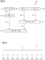
FIG 2 ein Flussdiagramm, welches ein Verfahren zur Validierung einer Funktion einer Sensoreinheit eines Schienenfahrzeugs zur Objektlokalisierung gemäß einem Ausführungsbeispiel der Erfindung veranschaulicht, -
FIG 3 eine schematische Darstellung eines Vorgangs zur Erstellung einer Karte mit Ego-Positionen, die das Schienenfahrzeug im Rahmen der Validierung anfährt, -
FIG 4 eine Darstellung der möglichen Fehler bei der Ermittlung der Ego-Position eines Schienenfahrzeugs und deren Auswirkungen auf eine Objektlokalisierung, -
FIG 5 eine Darstellung von Positionen von Objekten mit unterschiedlichen lateralen Abständen zu einer Mittenlinie einer Schienenstrecke, -
FIG 6 ein Schaubild, welches eine Ermittlung des minimalen Abstandes zwischen einem Punkt und einer konstruierten Strecke veranschaulicht, -
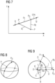
FIG 7 ein Schaubild, welches eine Ermittlung eines longitudinalen Abstandes zwischen einem Punkt und einem Hilfspunkt in longitudinaler Richtung veranschaulicht, -
FIG 8 einen Kreisabstand auf einer Sphäre, -
FIG 9 eine Darstellung von Winkelbeziehungen in einem Kreisbogen, -
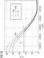
FIG 10 ein Schaubild, welches einen Validierungsprozess dokumentiert, -
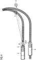
FIG 11 eine schematische Darstellung einer Anordnung zur Validierung einer Funktion einer Sensoreinheit eines Schienenfahrzeugs zur Objektlokalisierung gemäß einem zweiten Ausführungsbeispiel der Erfindung, -
FIG 12 eine schematische Darstellung einer Anordnung zur Validierung einer Funktion einer Sensoreinheit eines Schienenfahrzeugs zur Objektlokalisierung gemäß einem dritten Ausführungsbeispiel der Erfindung.
-
FIG 1 a schematic representation of an arrangement for validating a function of a sensor unit of a rail vehicle for object localization according to an exemplary embodiment of the invention, -
FIG 2 a flowchart illustrating a method for validating a function of a sensor unit of a rail vehicle for object localization according to an exemplary embodiment of the invention, -
FIG 3 a schematic representation of a process for creating a map with ego positions that the rail vehicle approaches as part of the validation, -
FIG 4 a representation of the possible errors when determining the ego position of a rail vehicle and their effects on object localization, -
FIG 5 a representation of positions of objects with different lateral distances from a center line of a rail route, -
FIG 6 a diagram illustrating a determination of the minimum distance between a point and a constructed route, -
FIG 7 a diagram illustrating a determination of a longitudinal distance between a point and an auxiliary point in the longitudinal direction, -
FIG 8 a circle distance on a sphere, -
FIG 9 a representation of angular relationships in a circular arc, -
FIG 10 a diagram that documents a validation process, -
FIG 11 a schematic representation of an arrangement for validating a function of a sensor unit of a rail vehicle for object localization according to a second exemplary embodiment of the invention, -
FIG 12 a schematic representation of an arrangement for validating a function of a sensor unit of a rail vehicle for object localization according to a third exemplary embodiment of the invention.
In
Das Testobjekt 3 ist in einem Abstand dr zur Mittenlinie 2a der Testschienenstrecke 2 angeordnet. Das Testobjekt 3 umfasst eine erste Selbstlokalisierungseinheit 4, in diesem Ausführungsbeispiel eine Satellitennavigationseinheit, zum Ermitteln einer Referenzposition RPT des Testobjekts 3. Hierzu empfängt die erste Selbstlokalisierungseinheit 4 ein Satellitensignal, auf dessen Basis sie die Referenzposition RPT des Testobjekts 3 ermittelt. Das Testobjekt 3 umfasst weiterhin eine Sendeeinheit 5 zum Übermitteln der ermittelten Referenzposition RPT des Testobjekts 3 an das Schienenfahrzeug 6 per Funk.The test object 3 is arranged at a distance d r from the
Das Schienenfahrzeug 6 umfasst die bereits erwähnte Sensoreinheit 7, in diesem Ausführungsbeispiel eine Lidareinheit, zur Detektion und Lokalisierung, d.h. zur Ermittlung einer Relativposition RLP des Testobjekts 3 zur Sensoreinheit 7. Hierzu misst die Sensoreinheit 7 den longitudinalen Abstand dl des Testobjekts 3 zu der Sensoreinheit 7 und den lateralen Abstand dr des Testobjekts 3 zur Mittenlinie 2a der Testschienenstrecke 2. Die Position und der Verlauf der Mittenlinie 2a können vorab durch ein Abfahren der Testschienenstrecke 2 und ein Erfassen der Ego-Position EP des Schienenfahrzeugs 6 an unterschiedlichen Stellen der Testschienenstrecke 2 ermittelt werden. Zur Ermittlung der Ego-Position EP umfasst das Schienenfahrzeug 6 eine zweite Selbstlokalisierungseinheit 9.The
Die zweite Selbstlokalisierungseinheit 9 umfasst in dem in
In
Bei dem Schritt 2.I wird eine Referenzposition RPT eines Testobjekts 3 durch eine in dem Testobjekt 3 angeordnete erste Selbstlokalisierungseinheit 4 ermittelt. Hierzu wird von der ersten Selbstlokalisierungseinheit 4, in diesem Ausführungsbeispiel eine Satellitennavigationseinheit, ein Satellitensignal PS empfangen.In step 2.I, a reference position RP T of a test object 3 is arranged in the test object 3 first self-localization unit 4 determined. For this purpose, a satellite signal PS is received by the first self-localization unit 4, in this exemplary embodiment a satellite navigation unit.
Bei dem Schritt 2.II wird die ermittelte Referenzposition RPT des Testobjekts 3 an eine Empfangseinheit 11 des Schienenfahrzeugs 6 durch eine an dem Testobjekt 3 angeordnete Sendeeinheit 5 übermittelt.In step 2.II, the determined reference position RP T of the test object 3 is transmitted to a receiving
Bei dem Schritt 2.III wird eine Relativposition RLP des Testobjekts 3 zu einer an dem Schienenfahrzeug 6 angeordneten Sensoreinheit 7 detektiert. Hierzu misst die Sensoreinheit 7, in dem in
Bei dem Schritt 2.IV wird zusätzlich eine Ego-Position EP des Schienenfahrzeugs 6 durch eine an dem Schienenfahrzeug 6 angeordnete zweite Selbstlokalisierungseinheit 9 ermittelt. Die Orientierung des Schienenfahrzeugs 6 ist anhand der bekannten Geometrie der Testschienenstrecke 2, beispielsweise verläuft die Testschienenstrecke 2 geradlinig, ebenfalls bekannt.In step 2.IV, an ego position EP of the
Bei dem Schritt 2.V wird eine Absolutposition AP des Testobjekts 3 auf Basis der detektierten Relativposition RLP des Testobjekts 3 zur Sensoreinheit 7 und der ermittelten Ego-Position EP sowie der bekannten Orientierung des Schienenfahrzeugs 6 ermittelt.In step 2.V, an absolute position AP of the test object 3 is determined based on the detected relative position RLP of the test object 3 to the sensor unit 7 and the determined ego position EP as well as the known orientation of the
Bei dem Schritt 2.VI wird die Objektlokalisierungsfunktion der Sensoreinheit 7 durch Ermitteln einer Abweichung AW der ermittelten Absolutposition AP des Testobjekts 3 von der Referenzposition RPT des Testobjekts 3 validiert.In step 2.VI, the object localization function of the sensor unit 7 is validated by determining a deviation AW of the determined absolute position AP of the test object 3 from the reference position RP T of the test object 3.
In
In ![]()
![]()
![]()
![]()
Der Vektor ![]()
![]()
Der kleinste Abstand dr ergibt sich als Projektion des Vektors ![]()
![]()
![]()
![]()
In
In
In ![]()
![]()
![]()
![]()
Wie im Zusammenhang mit
In
In
In
Bei dem dritten Ausführungsbeispiel weist die Anordnung 1 eine von dem Schienenfahrzeug 6 und dem Testobjekt 3 separate stationäre Auswertungseinrichtung 12 auf. Die stationäre Auswertungseinrichtung 12 umfasst in diesem Fall die Validierungseinheit 10 und eine Empfangseinheit 5" zum Empfangen der von der Positionsermittlungseinheit 8 des Schienenfahrzeugs 6 ermittelten Absolutposition AP des Testobjekts 3. Die Empfangseinheit 5" ist bei dem dritten Ausführungsbeispiel auch dazu eingerichtet, die Referenzposition RPT des Testobjekts 3 von dem Testobjekt 3 zu empfangen und die empfangenen Informationen AP, RPT an die Validierungseinheit 10 weiterzugeben. Die stationäre Auswertungseinrichtung 12 kann auch als sogenannter Remote-Computer ausgebildet sein und über ein Kommunikationsnetzwerk, beispielsweise das Internet, mit dem Testobjekt 3 und dem Schienenfahrzeug 6 in Verbindung stehen, um die vom Testobjekt 3 und dem Schienenfahrzeug 6 ermittelten Messdaten bzw. Informationen AP, RPT zu empfangen. Das Schienenfahrzeug 6 weist bei dem in
Es wird abschließend noch einmal darauf hingewiesen, dass es sich bei den vorbeschriebenen Verfahren und Vorrichtungen lediglich um bevorzugte Ausführungsbeispiele der Erfindung handelt und dass die Erfindung vom Fachmann variiert werden kann, ohne den Bereich der Erfindung zu verlassen, soweit er durch die Ansprüche vorgegeben ist. Es wird der Vollständigkeit halber auch darauf hingewiesen, dass die Verwendung der unbestimmten Artikel "ein" bzw. "eine" nicht ausschließt, dass die betreffenden Merkmale auch mehrfach vorhanden sein können. Ebenso schließt der Begriff "Einheit" nicht aus, dass diese aus mehreren Komponenten besteht, die gegebenenfalls auch räumlich verteilt sein können.Finally, it should be pointed out once again that the methods and devices described above are merely preferred exemplary embodiments of the invention and that the invention can be varied by a person skilled in the art without departing from the scope of the invention, insofar as it is specified by the claims. For the sake of completeness, it should also be noted that the use of the indefinite articles “a” or “an” does not exclude the fact that the characteristics in question can be present multiple times. Likewise, the term “unit” does not exclude the fact that it consists of several components, which may also be spatially distributed.
Claims (15)
Applications Claiming Priority (1)
| Application Number | Priority Date | Filing Date | Title |
|---|---|---|---|
| DE102022205527.6A DE102022205527A1 (en) | 2022-05-31 | 2022-05-31 | Validation of a sensor unit of a rail vehicle for object localization |
Publications (1)
| Publication Number | Publication Date |
|---|---|
| EP4286243A1 true EP4286243A1 (en) | 2023-12-06 |
Family
ID=85285303
Family Applications (1)
| Application Number | Title | Priority Date | Filing Date |
|---|---|---|---|
| EP23157523.4A Pending EP4286243A1 (en) | 2022-05-31 | 2023-02-20 | Validation of a sensor unit of a rail vehicle for object localization |
Country Status (2)
| Country | Link |
|---|---|
| EP (1) | EP4286243A1 (en) |
| DE (1) | DE102022205527A1 (en) |
Citations (3)
| Publication number | Priority date | Publication date | Assignee | Title |
|---|---|---|---|---|
| DE102006007788A1 (en) * | 2006-02-20 | 2007-08-30 | Siemens Ag | Computer-assisted driverless railway train monitoring system, to show its travel behavior, has train-mounted sensors and track position markers for position data to be compared with a stored model |
| EP3410145A1 (en) * | 2017-05-31 | 2018-12-05 | Valeo Schalter und Sensoren GmbH | Method for calibrating a radar sensor of a motor vehicle during a movement of the motor vehicle, radar sensor, driver assistance system and motor vehicle |
| DE102019206503A1 (en) * | 2019-05-07 | 2020-11-12 | Zf Friedrichshafen Ag | Method and control unit for operating an autonomous vehicle |
Family Cites Families (3)
| Publication number | Priority date | Publication date | Assignee | Title |
|---|---|---|---|---|
| US20190162820A1 (en) | 2017-11-29 | 2019-05-30 | Delphi Technologies, Llc | Automated vehicle sensor calibration system |
| DE102019206021A1 (en) | 2019-04-26 | 2020-10-29 | Robert Bosch Gmbh | Method for detecting the functionality of an environmental sensor, control unit and vehicle |
| DE102020212374A1 (en) | 2020-09-30 | 2022-03-31 | Siemens Mobility GmbH | Method for checking the calibration of an environment sensor arranged on a rail vehicle |
-
2022
- 2022-05-31 DE DE102022205527.6A patent/DE102022205527A1/en active Pending
-
2023
- 2023-02-20 EP EP23157523.4A patent/EP4286243A1/en active Pending
Patent Citations (3)
| Publication number | Priority date | Publication date | Assignee | Title |
|---|---|---|---|---|
| DE102006007788A1 (en) * | 2006-02-20 | 2007-08-30 | Siemens Ag | Computer-assisted driverless railway train monitoring system, to show its travel behavior, has train-mounted sensors and track position markers for position data to be compared with a stored model |
| EP3410145A1 (en) * | 2017-05-31 | 2018-12-05 | Valeo Schalter und Sensoren GmbH | Method for calibrating a radar sensor of a motor vehicle during a movement of the motor vehicle, radar sensor, driver assistance system and motor vehicle |
| DE102019206503A1 (en) * | 2019-05-07 | 2020-11-12 | Zf Friedrichshafen Ag | Method and control unit for operating an autonomous vehicle |
Also Published As
| Publication number | Publication date |
|---|---|
| DE102022205527A1 (en) | 2023-11-30 |
Similar Documents
| Publication | Publication Date | Title |
|---|---|---|
| EP3746346B1 (en) | Rail vehicle and method for surveying a track section | |
| DE102015100134B4 (en) | Method for detecting and tracking objects using multiple radar sensors | |
| DE102012014397B4 (en) | Method for determining a position of a vehicle and vehicle | |
| DE102015219551B4 (en) | Object detection device | |
| DE102008029613A1 (en) | A method of estimating the elevation of a target object using a radar data fusion | |
| DE102018117526A1 (en) | Method, apparatus and system for wireless support of motor vehicle trailers in various maneuvers | |
| DE102016221440A1 (en) | Method for diagnosing environmental sensor systems in vehicles | |
| DE102012006738A1 (en) | Method of controlling group of objects e.g. train with trailer, involves detecting direction, position or location of specific object such as trailer among group of objects such as train or convoy, and comparing to set point | |
| DE102016121928A1 (en) | Vehicle navigation system with position support of neighboring vehicles | |
| DE102017222017A1 (en) | Method and system for determining and providing a soil profile | |
| EP3060942B1 (en) | Method for determining a position of at least two sensors, and sensor network | |
| DE112014001069T5 (en) | Control system and method for controlling a vehicle in connection with the detection of an obstacle | |
| EP4077098A1 (en) | Method and monitoring system for determining a position of a rail vehicle | |
| EP3395632A1 (en) | Automatic and collaborative driverless transport system | |
| WO2018091508A1 (en) | Collision avoidance by measuring the course of the route of a vehicle | |
| DE3538908A1 (en) | Autonomous on-board locating system for determining the position and protecting against collision of robot and industrial trucks | |
| DE102020118629B4 (en) | Computer-implemented method for determining the validity of an estimated position of a vehicle | |
| EP3515787B1 (en) | Method for determining the position of a rail vehicle and rail vehicle having a position determining device | |
| WO2013037532A1 (en) | Device and method for determining a position of a vehicle | |
| DE102018221864A1 (en) | Method and system for determining a trajectory of a vehicle | |
| EP2995971A1 (en) | Method and system for positioning | |
| DE102017220004A1 (en) | Method and driver assistance system for controlling the driving dynamics of a vehicle | |
| EP4286243A1 (en) | Validation of a sensor unit of a rail vehicle for object localization | |
| DE102019206806A1 (en) | Determination of the speed and the distance of objects to a sensor system | |
| DE102018212975A1 (en) | parking aid |
Legal Events
| Date | Code | Title | Description |
|---|---|---|---|
| PUAI | Public reference made under article 153(3) epc to a published international application that has entered the european phase |
Free format text: ORIGINAL CODE: 0009012 |
|
| STAA | Information on the status of an ep patent application or granted ep patent |
Free format text: STATUS: THE APPLICATION HAS BEEN PUBLISHED |
|
| AK | Designated contracting states |
Kind code of ref document: A1 Designated state(s): AL AT BE BG CH CY CZ DE DK EE ES FI FR GB GR HR HU IE IS IT LI LT LU LV MC ME MK MT NL NO PL PT RO RS SE SI SK SM TR |