EP4286232B1 - Combined service brake and spring brake cylinder with service brake cylinder mounted inside the spring brake cylinder - Google Patents
Combined service brake and spring brake cylinder with service brake cylinder mounted inside the spring brake cylinder Download PDFInfo
- Publication number
- EP4286232B1 EP4286232B1 EP22177219.7A EP22177219A EP4286232B1 EP 4286232 B1 EP4286232 B1 EP 4286232B1 EP 22177219 A EP22177219 A EP 22177219A EP 4286232 B1 EP4286232 B1 EP 4286232B1
- Authority
- EP
- European Patent Office
- Prior art keywords
- spring
- service brake
- brake
- chamber
- service
- Prior art date
- Legal status (The legal status is an assumption and is not a legal conclusion. Google has not performed a legal analysis and makes no representation as to the accuracy of the status listed.)
- Active
Links
Images


Classifications
-
- B—PERFORMING OPERATIONS; TRANSPORTING
- B60—VEHICLES IN GENERAL
- B60T—VEHICLE BRAKE CONTROL SYSTEMS OR PARTS THEREOF; BRAKE CONTROL SYSTEMS OR PARTS THEREOF, IN GENERAL; ARRANGEMENT OF BRAKING ELEMENTS ON VEHICLES IN GENERAL; PORTABLE DEVICES FOR PREVENTING UNWANTED MOVEMENT OF VEHICLES; VEHICLE MODIFICATIONS TO FACILITATE COOLING OF BRAKES
- B60T17/00—Component parts, details, or accessories of power brake systems not covered by groups B60T8/00, B60T13/00 or B60T15/00, or presenting other characteristic features
- B60T17/08—Brake cylinders other than ultimate actuators
- B60T17/083—Combination of service brake actuators with spring loaded brake actuators
Definitions
- the present invention relates to a combined service brake and spring brake cylinder according to the preamble of claim 1, and to a pneumatic or electro-pneumatic vehicle brake comprising at least one combined service brake and spring brake cylinder according to claim 10.
- Combined pneumatic service brake and spring brake cylinders with a service brake function and a parking brake function are usually arranged on rear axles of commercial vehicles and usually have two compressed air ports.
- One compressed air port controls the parking brake function and is under a parking brake release pressure for compressing an accumulator spring of the spring brake cylinder when the commercial vehicles are in a driving state.
- the other compressed air port controls the service brake function and is vented in the driving condition to brake the commercial vehicle via the service brake.
- the service brake function is controlled by means of a usually in the form of a diaphragm cylinder. If the commercial vehicle is to be parked, the spring brake cylinder is released and the parking brake is applied via the spring tension of the accumulator spring.
- a combined service brake cylinder and spring brake cylinder is known, for example, from DE 10 2014 002 112 A1 .
- the spring brake cylinder and the service brake cylinder are arranged coaxially one behind the other and connected to each other by an intermediate flange.
- such an arrangement requires a relatively long installation space within the wheel arches of the commercial vehicles, which can cause space problems.
- a combined service brake cylinder and spring brake cylinder is proposed in DE 10 2014 002 112 A1 , in which the service brake cylinder and the spring brake cylinder are placed laterally next to one another, the accumulator spring being arranged there around the service brake cylinder.
- the service brake piston is guided within the spring brake piston and axially thereon, which has a radially inwardly extending circumferential edge which abuts against an end-face annular surface of the service brake piston in order to drive the service brake piston together with the service brake piston rod into the applied position when the parking brake is applied.
- this arrangement has some disadvantages.
- the radially inwardly extending peripheral edge of the spring brake piston is loaded by the service brake pressure in the service brake chamber, so that during service braking a force is generated at the spring brake piston directed against the spring brake release pressure in the spring brake chamber, which loads the spring brake piston in the application direction of the parking brake.
- the effective area of the spring brake piston on which the parking brake release pressure can act to hold the parking brake released is relatively small, resulting in a high required parking brake release pressure or a low spring stiffness of the accumulator spring, but with disadvantages in terms of compressed air consumption or parking brake force.
- JP 555160646 A discloses a brake cylinder according to the preamble of claim 1.
- a service brake piston and a spring brake piston are provided, where the piston rod is attached to the service brake piston which extends through the spring brake piston.
- a spring chamber where an accumulator spring is accommodated is connected with a return spring chamber where a return spring for the service brake piston is accommodated. This connection can cause an unwanted flow of dirt and/or air from one chamber to the other.
- the parking and service brake functions are affected by each other.
- the invention is based on a combined service brake and spring brake cylinder for operating a service brake and a parking brake, comprising:
- That the service brake cylinder, when viewed radially, is disposed within the spring brake cylinder may mean that the service brake cylinder, when viewed radially, is disposed completely within and enclosed by the wall of the spring brake cylinder. Further, it may mean that the service brake cylinder, when viewed axially, is disposed partially or completely within the spring brake cylinder.
- “Radial” and “axial” refer in particular to a common longitudinal axis of the combined service brake cylinder and spring brake cylinder, wherein the service brake cylinder and the spring brake cylinder are arranged in particular coaxially.
- a spring brake cylinder housing of the spring brake cylinder may comprise a closed housing of the spring brake cylinder, in which the service brake cylinder is then completely accommodated, for example.
- Directly guided should mean here, for example, that a radially outer circumferential surface of the service brake piston is guided on the radially inner circumferential surface of the service brake cylinder.
- a sealing element is preferably arranged therebetween, which, in addition to a sealing function, then also performs a guiding function for the service brake piston.
- the combined service brake and spring brake cylinder is short on the one hand, because the service brake cylinder is arranged radially and particularly also axially and particularly completely inside the spring brake cylinder.
- the spring brake piston can then also have a larger effective area in relation to the parking brake pressure, so that the pressure level of the parking brake release pressure and thus also the energy consumption can be reduced.
- the parking brake release pressure is the pressure at which the parking brake releases against the action of the at least one accumulator spring.
- the service brake cylinder may include an edge or a rim that is internally attached to the spring brake cylinder.
- a breathing device comprising at least:
- the second flow connection may comprise a through opening in the cylindrical wall or in the bottom of the service brake cylinder.
- the third flow connection may comprise a through opening in a wall or a cover of the spring brake cylinder.
- the third flow connection may comprise a filter and/or a valve that prevents dirt and moisture from entering the spring brake cylinder from the outside.
- the breathing valve may include a valve seat and a valve body biased away from the valve seat by spring means to the breathing valve open position, the valve body being urged against the valve seat by service braking pressure against the action of the spring means to move the breathing valve from the open position to the closed position.
- the breathing device may then be described by way of example as follows: For example, when the service brake chamber is pressurized, the breathing valve assumes the closed position so that no compressed air can pass from the service brake chamber into the return spring chamber. On the other hand, the moving service brake piston reduces the volume of the return spring chamber, thereby creating a first air flow which then passes through the second flow connection and the third flow connection to enter the atmosphere. Then, no excess pressure in the return spring chamber can impede the movement of the service brake piston in the service brake application direction.
- the volume of the spring chamber is reduced, thereby creating a second air flow which can then pass through the third flow connection to enter the atmosphere. Then, no excess pressure in the spring chamber can impede the movement of the spring brake piston in the parking brake release direction.
- the service brake piston may be connected to a service brake piston rod which actuates the service brake when the service brake chamber is pressurized by the service brake pressure and which releases the service brake when the service brake chamber is vented.
- the service brake piston rod can be formed by a cylindrical or rod-shaped body, to the end of which the service brake piston projecting radially outwards from this end is then attached.
- the spring brake piston may include a central opening having a bearing through which the spring brake piston is axially guided on the service brake piston rod and/or through which the service brake piston rod and the spring brake piston are axially movable relative to each other.
- the service brake piston rod may have, in particular at its radially outer periphery, a radial protrusion which forms an axial stop for the spring brake piston.
- the radial protrusion can then be arranged on the service brake piston rod in such a way that
- a particularly large effective area of the spring brake piston with respect to the parking brake release pressure results if the spring brake piston, viewed radially, extends from the central opening beyond a radially outer circumferential surface of the service brake cylinder to the radially inner circumferential surface of the spring brake cylinder.
- the effective surface of the spring brake piston on which the parking brake release pressure acts is then located, for example, on the side of the spring brake piston facing the spring brake chamber.
- the invention also relates to a pneumatic or electro-pneumatic vehicle brake comprising at least one combined service brake and spring brake cylinder described above.
- a combined pneumatic service brake and spring brake cylinder 1 having a service function and a parking brake function as described hereinafter is usually arranged on a wheel of a rear axle of commercial vehicles and usually has two compressed air ports 2, 5.
- a first compressed air port 2 controls the parking brake function and, in the driving state of commercial vehicles, is under a parking brake release pressure for compressing an accumulator spring 3 of a spring brake cylinder 4.
- a second compressed air port 5 controls the service brake function and, particularly in the driving state, can be pressurized to brake the commercial vehicle via the service brake.
- the service brake function is carried out by means of a service brake cylinder 6 designed as a diaphragm cylinder or brake piston cylinder. If the commercial vehicle is to be parked, the spring brake cylinder 4 is vented and the parking brake is applied via the spring tension of the accumulator spring 3.
- Fig. 1 shows a perspective view of a preferred embodiment of a combined service brake and spring brake cylinder 1 of an electro-pneumatic brake system of a commercial vehicle according to the invention, looking at one end face from which a first actuating element 7, for example for a disc brake, can be seen.
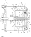
- Fig. 2 represents a perspective view of the combined service brake and spring brake cylinder 1 of Fig. 1 , looking at the other end face from which a second actuating element 8 of an emergency release device 9 protrudes.
- the combined service brake and spring brake cylinder 1 comprises the spring brake cylinder 4, a spring brake piston 10 axially slidably guided therein, and the accumulator spring 3 loading the spring brake piston 10 in an applied position of the parking brake.
- the spring brake cylinder 4 comprises a substantially cylindrical spring brake cylinder housing 11 with here, for example, two covers 12, 13 attached to the end faces, wherein the first actuating element 7 for the disc brake projects from a central through-opening of a first cover 13 and the second actuating element 8 of the emergency release device 9 projects from a central through-opening of a second cover 12.
- the spring brake cylinder housing 11 could also be pot-shaped and then have, for example, only one cover.
- the spring brake cylinder housing 11 forms a closed housing of the spring brake cylinder 4, in which the service brake cylinder 6 is completely excluded here, for example.
- the spring brake piston 10 is axially displaceably guided on a radially inner circumferential surface of the spring brake cylinder 4 or of the spring brake cylinder housing 11, wherein a first movement seal 14 is arranged between a radially outer edge of the spring brake piston 10 and the radially inner circumferential surface of the spring brake cylinder 4 or of the spring brake cylinder housing 11, a first movement seal 14 is arranged which is connected here to the radially outer edge of the spring brake piston 10 and which, in addition to a sealing function, also performs a guide function for the spring brake piston 10.
- the spring brake piston 10 With its one side facing away from the accumulator spring 3, the spring brake piston 10 delimits a spring brake chamber 15 which can be pressurized and vented by a parking brake pressure via the first compressed air connection 2.
- the accumulator spring 3 is then supported with its one end on the other side of the spring brake piston 10, the other end of which is supported on the spring brake cylinder housing 11.
- the first air pressure port 2 is formed, for example, in the first cover 13. However, it could also be formed in a bottom of the spring brake cylinder or the spring brake cylinder housing 11 of the spring brake cylinder 4 if the spring brake cylinder housing 11 is pot-shaped, for example.
- the accumulator spring 3 is then accommodated in a spring chamber 16 which is formed here as an annular chamber and is radially outer with respect to the service brake cylinder 6, and which is limited or bounded radially inwardly by a radially outer circumferential surface of a service brake cylinder housing 17 of the service brake cylinder 6 and radially outwardly by the radially inner circumferential surface of the spring brake cylinder housing 11.
- the spring chamber 16 is limited or bounded by the spring brake piston 10 and the spring brake cylinder housing 11.
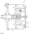
- the service brake cylinder 6 or the service brake cylinder housing 17 directly guides an axially displaceable service brake piston 18, the service brake cylinder 6 and the service brake piston 18 delimiting a service brake chamber 19 which can be pressurized and vented with a service brake pressure via the second compressed air port 5.
- the service brake cylinder 6 or the service brake cylinder housing 17 of the service brake cylinder 6 is arranged radially and here, for example, also axially, preferably completely within the spring brake cylinder 4 or within the spring brake cylinder housing 11 of the spring brake cylinder 4.
- the service brake piston 18 is axially slidably guided directly on the radially inner peripheral surface of the service brake cylinder 6 or the service brake cylinder housing 17. This direct guidance includes that a second movement seal 20 is arranged therebetween, which here is connected to the radially outer edge of the service brake piston 18 in addition to a sealing function also performs a guiding function for the service brake piston 18.
- a diaphragm cooperating with the service brake piston 18 may, for example, be attached with its radially outer edge to the service brake cylinder 6 and/or to the spring brake cylinder 4.
- the service brake cylinder 6 is then a so-called diaphragm cylinder.
- the service brake piston 18, which is then smaller in its radial extension forms a pressure plate, for example a central pressure plate, on which the diaphragm acts, is connected with or on which the diaphragm is supported.
- the diaphragm may, for example, be secured to or in a joint between the service brake cylinder 6 and the spring brake cylinder 4.
- a radially outer edge of the diaphragm is clamped between the service brake cylinder 6 and the spring brake cylinder 4.
- the radially outer edge of the diaphragm may be clamped between the second cover 12 of the spring brake cylinder 4 and an edge 21 of the service brake cylinder 6, which is preferably pot-shaped, as in this case.
- the service brake piston 18 is connected to a service brake piston rod 22, which is made hollow here, for example, to receive the emergency release device 9 in its interior.
- the service brake piston rod 22 then actuates the service brake via the second actuating element 7 when the service brake chamber 19 is pressurized with a service brake application pressure, and which releases the service brake when the service brake chamber 19 is vented.
- the end of the service brake piston rod 22 facing the service brake chamber 19 can then project radially outwardly away from the service brake piston rod 22 in a mushroom-like manner.
- the emergency release device 9 for manual emergency release of the combined service brake and spring brake cylinder 1 which is not described in detail here, may be accommodated or integrated in the service brake piston rod 22.
- the service brake piston rod 22 can then be screwed into the release position of the parking brake or the service brake.
- Such manual emergency release is necessary in particular if no more parking brake release pressure can be generated in the spring brake chamber 15, for example, due to an electrical defect in the solenoid valve device or in its control system or also in the event of a power failure.
- the service brake cylinder 6 or the service brake cylinder housing 17 is here, for example, of pot-shaped design and has a cylindrical wall 37 extending in parallel into the spring brake cylinder 4 or into the spring brake cylinder housing 1, and a bottom 23.
- the bottom 23 is provided, for example, with a central opening through which the service brake piston rod 22 then projects into the spring brake cylinder 4 or into the spring brake chamber 15.
- the service brake piston rod 22 penetrates the spring brake chamber 15 centrally and then receives the first actuating element 7 for the disc brake in a recess at its end facing the disc brake and projecting out of the spring brake cylinder housing 11 through the through-opening.
- a return spring chamber 24 is formed here between the service brake piston 18 and the bottom 23 of the service brake cylinder 6, with a return spring 25 which loads the service brake piston 18 into the service brake release position. Also, the return spring chamber 24 is penetrated axially and centrally by the service brake piston rod 22.
- the here for example pot-shaped service brake cylinder 6 has the free edge 21 which is preferably fixed to the spring brake cylinder 4 on the inside, in particular in the region of the fixing of the end-face second cover 12 to the spring brake cylinder 4, whereby this second cover 12 also delimits or closes the service brake chamber 19.
- the service brake chamber 19 which can be ventilated and exhausted is delimited by the cylindrical wall 37 of the service brake cylinder housing 17, the second cover 12 of the spring brake cylinder 4 and the service brake piston 18 or, alternatively, by the above-mentioned diaphragm in the case a the above-mentioned diaphragm cylinder used as the service brake cylinder 6.
- the spring brake piston 10 contacts the bottom 23 of the service brake cylinder 6 from the outside with respect to the service brake cylinder 6 with its side facing away from the spring brake chamber 15. This contact is caused by the parking brake release pressure acting on the spring brake piston 10.
- the spring brake piston 10 includes a central opening having a bearing 26 through which the spring brake piston 10 is axially guided on the service brake piston rod 22.
- the bearing 26 therefore allows the service brake piston rod 22 and the spring brake piston 10 to move axially relative to each other.
- the bearing 26 is designed, for example, as a sealing bearing.
- the spring brake piston 10 then extends, viewed radially, from the bearing 26 or from the central opening of the spring brake piston 10 beyond a radially outer circumferential surface of the service brake cylinder 6 or of the service brake cylinder housing 17 to the radially inner circumferential surface of the spring brake cylinder 4 or of the spring brake cylinder housing 11.
- the effective surface of the spring brake piston 10 on which the parking brake pressure or the parking brake release pressure acts is located on the side of the spring brake piston 10 facing the spring brake chamber 15 and then also extends from the bearing 26 or from the central opening of the spring brake piston 10 to the radially inner circumferential surface of the spring brake cylinder 4 or of the spring brake cylinder housing 11.
- the effective surface of the spring brake piston 10 on which the parking brake pressure or the parking brake release pressure acts is located on the side of the spring brake piston 10 facing the spring brake chamber 15.
- the effective surface of the spring brake piston 10 also extends from the bearing 26 or from the central opening of the spring brake piston 10 beyond the radially outer circumferential surface of the service brake cylinder 6 or of the service brake cylinder housing 17 to the radially inner circumferential surface of the spring brake cylinder 4 or of the spring brake cylinder housing 11.
- the service brake piston rod 22 has, in particular at its radially outer periphery, a radial protrusion 27 which forms an axial stop for the bearing 26 or for the central opening of the spring brake piston 10.
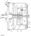
- This radial protrusion 27 is arranged on the service brake piston rod 22, for example, in such a way that the spring brake piston 10 brings the service brake piston rod 22 into the spring brake application position by abutting against the radial protrusion 27 when the spring brake chamber 15 is vented to apply the parking brake, as shown in Fig. 5 .
- the spring brake piston 10 together with the service brake piston 18, can move the service brake piston rod 22 to the spring brake application position and the service brake application position when the spring brake chamber 15 is vented and when the service brake chamber 19 is pressurized, as can be readily imagined with reference to Fig. 5 . Therefore, the service brake piston rod 22 connected to the service brake piston 18 and acting axially on the first disc brake actuating member 7 actuates both the service brake and the parking brake respectively by applying the disc brake.
- a breathing device which comprises, for example, a breathing valve 28 which is arranged here, for example, in a through-opening of the service brake piston 18 and is controlled by the service brake pressure in the service brake chamber 19.
- the breathing valve 28 may comprise, for example, a valve seat 30 formed in a valve body 29 and a valve body 32 biased by a spring 31 away from the valve seat 30 into the open position of the breathing valve 28, the valve body 32 being urged against the valve seat 30 by the service brake pressure acting on it against the force of the spring 31 to move the breathing valve 28 from the spring biased open position to the closed position.
- Fig. 6 shows the open position and Fig. 7 the closed position of the breathing valve 28.
- the breathing valve 28 can then assume the open position in which a first flow connection 33 through the through opening between the service brake chamber 19 and the return spring chamber 24 is open due to the bias of the spring 31.
- the breathing valve 28 is then moved from the open position to the closed position in which the first flow connection 33 through the through opening is blocked because the flow caused by the service brake pressure first passes through a radially outer gap 38 between the valve body 32 and the valve base body 29, and then also passes through the through opening in the service brake piston.
- some time i.e.
- the pressure exerted on the valve body 32 becomes so great that a sealing portion 34 of the valve body 32 comes into contact with the valve seat 30, thereby closing the first flow connection 33 or the through-opening. This prevents compressed air from then still flowing from the service brake chamber 19 into the return spring chamber 24.
- an in particular always open second flow connection 35 between the return spring chamber 24 and the spring chamber 16 can be components of the breathing device.
- the second flow connection 35 may comprise a through opening in the cylindrical wall 37 or in the bottom 23 of the service brake cylinder 6 or the service brake cylinder housing 17.
- the third flow connection 36 indicated in Fig. 1 may comprise a through opening in the spring brake cylinder housing 11, in particular a through opening on the front side. Consequently, the second flow connection 35 and the third flow connection 36 open into the spring chamber 16 here and also communicate with each other through the spring chamber 16.
- the third flow connection 36 may comprise a filter and/or a valve, for example in a cap, to prevent dirt and moisture from entering the spring brake cylinder 4 from the outside.
- the breathing device may then be described by way of example as follows: For example, as described above, when the service brake chamber 19 is pressurized, the breathing valve 28 assumes the closed position so that no compressed air can pass from the service brake chamber 19 into the return spring chamber 24. On the other hand, the volume of the return spring chamber 24 is reduced by the shifting or moving service brake piston 18, thereby creating a first air flow which then passes the second flow connection 35 and the third flow connection 36 to enter the atmosphere. Then, no excess pressure in the return spring chamber 24 can impede the movement of the service brake piston 18 in the service brake application direction.
Landscapes
- Engineering & Computer Science (AREA)
- Transportation (AREA)
- Mechanical Engineering (AREA)
- Braking Systems And Boosters (AREA)
- Braking Arrangements (AREA)
Priority Applications (5)
| Application Number | Priority Date | Filing Date | Title |
|---|---|---|---|
| EP22177219.7A EP4286232B1 (en) | 2022-06-03 | 2022-06-03 | Combined service brake and spring brake cylinder with service brake cylinder mounted inside the spring brake cylinder |
| PL22177219.7T PL4286232T3 (pl) | 2022-06-03 | 2022-06-03 | Połączony cylinder hamulca roboczego i hamulca sprężynowego z cylindrem hamulca roboczego zamontowanym wewnątrz cylindra hamulca sprężynowego |
| EP23730428.2A EP4486612A1 (en) | 2022-06-03 | 2023-05-31 | Combined service brake and spring brake cylinder with service brake cylinder mounted inside the spring brake cylinder |
| PCT/EP2023/064561 WO2023232877A1 (en) | 2022-06-03 | 2023-05-31 | Combined service brake and spring brake cylinder with service brake cylinder mounted inside the spring brake cylinder |
| CN202380035783.4A CN119173428A (zh) | 2022-06-03 | 2023-05-31 | 具有安装在弹簧制动缸内的行车制动缸的组合式行车制动缸和弹簧制动缸 |
Applications Claiming Priority (1)
| Application Number | Priority Date | Filing Date | Title |
|---|---|---|---|
| EP22177219.7A EP4286232B1 (en) | 2022-06-03 | 2022-06-03 | Combined service brake and spring brake cylinder with service brake cylinder mounted inside the spring brake cylinder |
Publications (2)
| Publication Number | Publication Date |
|---|---|
| EP4286232A1 EP4286232A1 (en) | 2023-12-06 |
| EP4286232B1 true EP4286232B1 (en) | 2025-02-26 |
Family
ID=81940502
Family Applications (2)
| Application Number | Title | Priority Date | Filing Date |
|---|---|---|---|
| EP22177219.7A Active EP4286232B1 (en) | 2022-06-03 | 2022-06-03 | Combined service brake and spring brake cylinder with service brake cylinder mounted inside the spring brake cylinder |
| EP23730428.2A Pending EP4486612A1 (en) | 2022-06-03 | 2023-05-31 | Combined service brake and spring brake cylinder with service brake cylinder mounted inside the spring brake cylinder |
Family Applications After (1)
| Application Number | Title | Priority Date | Filing Date |
|---|---|---|---|
| EP23730428.2A Pending EP4486612A1 (en) | 2022-06-03 | 2023-05-31 | Combined service brake and spring brake cylinder with service brake cylinder mounted inside the spring brake cylinder |
Country Status (4)
| Country | Link |
|---|---|
| EP (2) | EP4286232B1 (pl) |
| CN (1) | CN119173428A (pl) |
| PL (1) | PL4286232T3 (pl) |
| WO (1) | WO2023232877A1 (pl) |
Family Cites Families (6)
| Publication number | Priority date | Publication date | Assignee | Title |
|---|---|---|---|---|
| JPS55160646A (en) * | 1979-05-29 | 1980-12-13 | Nippon Air Brake Co Ltd | Brake cylinder |
| DE3625815A1 (de) * | 1986-07-30 | 1988-02-18 | Teves Gmbh Alfred | Kraftfahrzeugbremsvorrichtung |
| DE4010363A1 (de) * | 1990-03-30 | 1991-10-02 | Knorr Bremse Ag | Kombinierter betriebsbrems- und federspeicherbremszylinder fuer bremsanlagen von fahrzeugen, insbesondere nutzfahrzeugen |
| US6702072B2 (en) * | 2002-04-18 | 2004-03-09 | Westinghouse Air Brake Technologies Corporation | Brake cylinder unit |
| KR101712305B1 (ko) * | 2013-04-03 | 2017-03-03 | 나부테스코 가부시키가이샤 | 브레이크 실린더 장치 및 브레이크 장치 |
| DE102014002112A1 (de) | 2014-02-15 | 2015-08-20 | Man Truck & Bus Ag | Bremszylinder für Kraftfahrzeug-Bremse |
-
2022
- 2022-06-03 PL PL22177219.7T patent/PL4286232T3/pl unknown
- 2022-06-03 EP EP22177219.7A patent/EP4286232B1/en active Active
-
2023
- 2023-05-31 WO PCT/EP2023/064561 patent/WO2023232877A1/en not_active Ceased
- 2023-05-31 CN CN202380035783.4A patent/CN119173428A/zh active Pending
- 2023-05-31 EP EP23730428.2A patent/EP4486612A1/en active Pending
Also Published As
| Publication number | Publication date |
|---|---|
| PL4286232T3 (pl) | 2025-04-28 |
| WO2023232877A1 (en) | 2023-12-07 |
| EP4486612A1 (en) | 2025-01-08 |
| EP4286232A1 (en) | 2023-12-06 |
| CN119173428A (zh) | 2024-12-20 |
Similar Documents
| Publication | Publication Date | Title |
|---|---|---|
| EP0649493B1 (en) | Spring chamber isolation system for a fluid-operated brake actuator | |
| EP2792558B1 (en) | Spring brake actuator | |
| US6247764B1 (en) | Full function valve for heavy duty semi-trailer brake systems | |
| CA2373384C (en) | Sealed brake actuator | |
| US5460076A (en) | Fluid-operated brake actuator with internal check valve | |
| JPH0331050A (ja) | 負圧ブレーキブースタ | |
| US4505114A (en) | Power booster | |
| US8196718B2 (en) | Combined service brake and stored-energy brake cylinder with internal ventilation | |
| USRE32885E (en) | Air brake with collet locked push rod and air supply system | |
| US4589704A (en) | Air brake with collet locked push rod and air supply system | |
| JP2009509866A (ja) | 内部空気逃し手段を備えた常用ブレーキシリンダとばね付勢ブレーキシリンダとの複合体 | |
| US4967560A (en) | Parking sustainer employing liquid pressure booster | |
| EP4286232B1 (en) | Combined service brake and spring brake cylinder with service brake cylinder mounted inside the spring brake cylinder | |
| US5779326A (en) | Actuating unit for a locking-protected motor vehicle brake system | |
| US6148711A (en) | Normally-closed diaphragm check valve | |
| JPH03500279A (ja) | 自動車用アンチロック装置付ブレーキユニット | |
| CN102245452B (zh) | 带有外部排气装置的弹簧储能制动缸 | |
| JPH0215422B2 (pl) | ||
| US5711203A (en) | Pneumatic brake booster | |
| EP4563424A1 (en) | Combined service brake and parking brake cylinder and pneumatic or electro-pneumatic vehicle brake | |
| CN110461666B (zh) | 不具有支撑环并且不具有支撑盘的隔膜阀 | |
| US4068900A (en) | Blend back proportioning brake control apparatus | |
| JP2592306B2 (ja) | 2つの回路で駆動制御可能な制動圧力制御弁 | |
| KR20060133580A (ko) | 차량용 잠금 장치를 갖춘 유압 브레이크 및 유압브레이크의 작동 방법 | |
| HK40116311A (zh) | 具有安装在弹簧制动缸内的行车制动缸的组合式行车制动缸和弹簧制动缸 |
Legal Events
| Date | Code | Title | Description |
|---|---|---|---|
| PUAI | Public reference made under article 153(3) epc to a published international application that has entered the european phase |
Free format text: ORIGINAL CODE: 0009012 |
|
| STAA | Information on the status of an ep patent application or granted ep patent |
Free format text: STATUS: THE APPLICATION HAS BEEN PUBLISHED |
|
| AK | Designated contracting states |
Kind code of ref document: A1 Designated state(s): AL AT BE BG CH CY CZ DE DK EE ES FI FR GB GR HR HU IE IS IT LI LT LU LV MC MK MT NL NO PL PT RO RS SE SI SK SM TR |
|
| RAP3 | Party data changed (applicant data changed or rights of an application transferred) |
Owner name: KNORR-BREMSE SYSTEME FUER NUTZFAHRZEUGE GMBH |
|
| STAA | Information on the status of an ep patent application or granted ep patent |
Free format text: STATUS: REQUEST FOR EXAMINATION WAS MADE |
|
| 17P | Request for examination filed |
Effective date: 20240606 |
|
| RBV | Designated contracting states (corrected) |
Designated state(s): AL AT BE BG CH CY CZ DE DK EE ES FI FR GB GR HR HU IE IS IT LI LT LU LV MC MK MT NL NO PL PT RO RS SE SI SK SM TR |
|
| GRAP | Despatch of communication of intention to grant a patent |
Free format text: ORIGINAL CODE: EPIDOSNIGR1 |
|
| STAA | Information on the status of an ep patent application or granted ep patent |
Free format text: STATUS: GRANT OF PATENT IS INTENDED |
|
| INTG | Intention to grant announced |
Effective date: 20240926 |
|
| GRAS | Grant fee paid |
Free format text: ORIGINAL CODE: EPIDOSNIGR3 |
|
| GRAA | (expected) grant |
Free format text: ORIGINAL CODE: 0009210 |
|
| STAA | Information on the status of an ep patent application or granted ep patent |
Free format text: STATUS: THE PATENT HAS BEEN GRANTED |
|
| AK | Designated contracting states |
Kind code of ref document: B1 Designated state(s): AL AT BE BG CH CY CZ DE DK EE ES FI FR GB GR HR HU IE IS IT LI LT LU LV MC MK MT NL NO PL PT RO RS SE SI SK SM TR |
|
| REG | Reference to a national code |
Ref country code: GB Ref legal event code: FG4D |
|
| REG | Reference to a national code |
Ref country code: CH Ref legal event code: EP |
|
| REG | Reference to a national code |
Ref country code: DE Ref legal event code: R096 Ref document number: 602022011007 Country of ref document: DE |
|
| REG | Reference to a national code |
Ref country code: SE Ref legal event code: TRGR |
|
| P01 | Opt-out of the competence of the unified patent court (upc) registered |
Free format text: CASE NUMBER: APP_7578/2025 Effective date: 20250213 |
|
| REG | Reference to a national code |
Ref country code: IE Ref legal event code: FG4D |
|
| REG | Reference to a national code |
Ref country code: NL Ref legal event code: MP Effective date: 20250226 |
|
| PG25 | Lapsed in a contracting state [announced via postgrant information from national office to epo] |
Ref country code: RS Free format text: LAPSE BECAUSE OF FAILURE TO SUBMIT A TRANSLATION OF THE DESCRIPTION OR TO PAY THE FEE WITHIN THE PRESCRIBED TIME-LIMIT Effective date: 20250526 |
|
| PG25 | Lapsed in a contracting state [announced via postgrant information from national office to epo] |
Ref country code: FI Free format text: LAPSE BECAUSE OF FAILURE TO SUBMIT A TRANSLATION OF THE DESCRIPTION OR TO PAY THE FEE WITHIN THE PRESCRIBED TIME-LIMIT Effective date: 20250226 |
|
| PGFP | Annual fee paid to national office [announced via postgrant information from national office to epo] |
Ref country code: DE Payment date: 20250626 Year of fee payment: 4 Ref country code: PL Payment date: 20250507 Year of fee payment: 4 |
|
| PG25 | Lapsed in a contracting state [announced via postgrant information from national office to epo] |
Ref country code: ES Free format text: LAPSE BECAUSE OF FAILURE TO SUBMIT A TRANSLATION OF THE DESCRIPTION OR TO PAY THE FEE WITHIN THE PRESCRIBED TIME-LIMIT Effective date: 20250226 |
|
| REG | Reference to a national code |
Ref country code: LT Ref legal event code: MG9D |
|
| PG25 | Lapsed in a contracting state [announced via postgrant information from national office to epo] |
Ref country code: NO Free format text: LAPSE BECAUSE OF FAILURE TO SUBMIT A TRANSLATION OF THE DESCRIPTION OR TO PAY THE FEE WITHIN THE PRESCRIBED TIME-LIMIT Effective date: 20250526 Ref country code: IS Free format text: LAPSE BECAUSE OF FAILURE TO SUBMIT A TRANSLATION OF THE DESCRIPTION OR TO PAY THE FEE WITHIN THE PRESCRIBED TIME-LIMIT Effective date: 20250626 |
|
| PG25 | Lapsed in a contracting state [announced via postgrant information from national office to epo] |
Ref country code: NL Free format text: LAPSE BECAUSE OF FAILURE TO SUBMIT A TRANSLATION OF THE DESCRIPTION OR TO PAY THE FEE WITHIN THE PRESCRIBED TIME-LIMIT Effective date: 20250226 |
|
| PG25 | Lapsed in a contracting state [announced via postgrant information from national office to epo] |
Ref country code: HR Free format text: LAPSE BECAUSE OF FAILURE TO SUBMIT A TRANSLATION OF THE DESCRIPTION OR TO PAY THE FEE WITHIN THE PRESCRIBED TIME-LIMIT Effective date: 20250226 |
|
| PG25 | Lapsed in a contracting state [announced via postgrant information from national office to epo] |
Ref country code: PT Free format text: LAPSE BECAUSE OF FAILURE TO SUBMIT A TRANSLATION OF THE DESCRIPTION OR TO PAY THE FEE WITHIN THE PRESCRIBED TIME-LIMIT Effective date: 20250626 Ref country code: LV Free format text: LAPSE BECAUSE OF FAILURE TO SUBMIT A TRANSLATION OF THE DESCRIPTION OR TO PAY THE FEE WITHIN THE PRESCRIBED TIME-LIMIT Effective date: 20250226 |
|
| PGFP | Annual fee paid to national office [announced via postgrant information from national office to epo] |
Ref country code: FR Payment date: 20250624 Year of fee payment: 4 |
|
| PG25 | Lapsed in a contracting state [announced via postgrant information from national office to epo] |
Ref country code: BG Free format text: LAPSE BECAUSE OF FAILURE TO SUBMIT A TRANSLATION OF THE DESCRIPTION OR TO PAY THE FEE WITHIN THE PRESCRIBED TIME-LIMIT Effective date: 20250226 Ref country code: GR Free format text: LAPSE BECAUSE OF FAILURE TO SUBMIT A TRANSLATION OF THE DESCRIPTION OR TO PAY THE FEE WITHIN THE PRESCRIBED TIME-LIMIT Effective date: 20250527 |
|
| PGFP | Annual fee paid to national office [announced via postgrant information from national office to epo] |
Ref country code: TR Payment date: 20250514 Year of fee payment: 4 |
|
| PGFP | Annual fee paid to national office [announced via postgrant information from national office to epo] |
Ref country code: SE Payment date: 20250619 Year of fee payment: 4 |
|
| REG | Reference to a national code |
Ref country code: AT Ref legal event code: MK05 Ref document number: 1770373 Country of ref document: AT Kind code of ref document: T Effective date: 20250226 |
|
| PG25 | Lapsed in a contracting state [announced via postgrant information from national office to epo] |
Ref country code: SM Free format text: LAPSE BECAUSE OF FAILURE TO SUBMIT A TRANSLATION OF THE DESCRIPTION OR TO PAY THE FEE WITHIN THE PRESCRIBED TIME-LIMIT Effective date: 20250226 |
|
| PG25 | Lapsed in a contracting state [announced via postgrant information from national office to epo] |
Ref country code: DK Free format text: LAPSE BECAUSE OF FAILURE TO SUBMIT A TRANSLATION OF THE DESCRIPTION OR TO PAY THE FEE WITHIN THE PRESCRIBED TIME-LIMIT Effective date: 20250226 |
|
| PG25 | Lapsed in a contracting state [announced via postgrant information from national office to epo] |
Ref country code: IT Free format text: LAPSE BECAUSE OF FAILURE TO SUBMIT A TRANSLATION OF THE DESCRIPTION OR TO PAY THE FEE WITHIN THE PRESCRIBED TIME-LIMIT Effective date: 20250226 |
|
| PG25 | Lapsed in a contracting state [announced via postgrant information from national office to epo] |
Ref country code: AT Free format text: LAPSE BECAUSE OF FAILURE TO SUBMIT A TRANSLATION OF THE DESCRIPTION OR TO PAY THE FEE WITHIN THE PRESCRIBED TIME-LIMIT Effective date: 20250226 |
|
| PG25 | Lapsed in a contracting state [announced via postgrant information from national office to epo] |
Ref country code: EE Free format text: LAPSE BECAUSE OF FAILURE TO SUBMIT A TRANSLATION OF THE DESCRIPTION OR TO PAY THE FEE WITHIN THE PRESCRIBED TIME-LIMIT Effective date: 20250226 Ref country code: CZ Free format text: LAPSE BECAUSE OF FAILURE TO SUBMIT A TRANSLATION OF THE DESCRIPTION OR TO PAY THE FEE WITHIN THE PRESCRIBED TIME-LIMIT Effective date: 20250226 |
|
| PG25 | Lapsed in a contracting state [announced via postgrant information from national office to epo] |
Ref country code: RO Free format text: LAPSE BECAUSE OF FAILURE TO SUBMIT A TRANSLATION OF THE DESCRIPTION OR TO PAY THE FEE WITHIN THE PRESCRIBED TIME-LIMIT Effective date: 20250226 |
|
| PG25 | Lapsed in a contracting state [announced via postgrant information from national office to epo] |
Ref country code: SK Free format text: LAPSE BECAUSE OF FAILURE TO SUBMIT A TRANSLATION OF THE DESCRIPTION OR TO PAY THE FEE WITHIN THE PRESCRIBED TIME-LIMIT Effective date: 20250226 |
|
| REG | Reference to a national code |
Ref country code: DE Ref legal event code: R097 Ref document number: 602022011007 Country of ref document: DE |
|
| PLBE | No opposition filed within time limit |
Free format text: ORIGINAL CODE: 0009261 |
|
| STAA | Information on the status of an ep patent application or granted ep patent |
Free format text: STATUS: NO OPPOSITION FILED WITHIN TIME LIMIT |
|
| REG | Reference to a national code |
Ref country code: CH Ref legal event code: L10 Free format text: ST27 STATUS EVENT CODE: U-0-0-L10-L00 (AS PROVIDED BY THE NATIONAL OFFICE) Effective date: 20260107 |
|
| REG | Reference to a national code |
Ref country code: CH Ref legal event code: H13 Free format text: ST27 STATUS EVENT CODE: U-0-0-H10-H13 (AS PROVIDED BY THE NATIONAL OFFICE) Effective date: 20260127 |
|
| PG25 | Lapsed in a contracting state [announced via postgrant information from national office to epo] |
Ref country code: MC Free format text: LAPSE BECAUSE OF FAILURE TO SUBMIT A TRANSLATION OF THE DESCRIPTION OR TO PAY THE FEE WITHIN THE PRESCRIBED TIME-LIMIT Effective date: 20250226 |
|
| 26N | No opposition filed |
Effective date: 20251127 |