EP4286186A1 - Vehicle window sealing strip guide rail and vehicle body side triangular window structure - Google Patents
Vehicle window sealing strip guide rail and vehicle body side triangular window structure Download PDFInfo
- Publication number
- EP4286186A1 EP4286186A1 EP21921750.2A EP21921750A EP4286186A1 EP 4286186 A1 EP4286186 A1 EP 4286186A1 EP 21921750 A EP21921750 A EP 21921750A EP 4286186 A1 EP4286186 A1 EP 4286186A1
- Authority
- EP
- European Patent Office
- Prior art keywords
- connecting plate
- guide rail
- sealing strip
- clamping
- pillar
- Prior art date
- Legal status (The legal status is an assumption and is not a legal conclusion. Google has not performed a legal analysis and makes no representation as to the accuracy of the status listed.)
- Pending
Links
- 238000007789 sealing Methods 0.000 title claims abstract description 76
- 238000001746 injection moulding Methods 0.000 claims abstract description 33
- 229910052751 metal Inorganic materials 0.000 claims description 38
- 239000002184 metal Substances 0.000 claims description 38
- 239000005357 flat glass Substances 0.000 claims description 31
- 238000004519 manufacturing process Methods 0.000 abstract description 9
- 239000003292 glue Substances 0.000 description 16
- 230000000694 effects Effects 0.000 description 10
- 230000006872 improvement Effects 0.000 description 9
- 125000000484 butyl group Chemical group [H]C([*])([H])C([H])([H])C([H])([H])C([H])([H])[H] 0.000 description 6
- 230000000007 visual effect Effects 0.000 description 6
- 238000000034 method Methods 0.000 description 5
- 230000008569 process Effects 0.000 description 5
- 239000000243 solution Substances 0.000 description 4
- 229910000838 Al alloy Inorganic materials 0.000 description 3
- 239000011521 glass Substances 0.000 description 3
- 238000012423 maintenance Methods 0.000 description 3
- 238000004026 adhesive bonding Methods 0.000 description 2
- 238000000576 coating method Methods 0.000 description 2
- 241000283730 Bos primigenius Species 0.000 description 1
- 239000011248 coating agent Substances 0.000 description 1
- 239000011152 fibreglass Substances 0.000 description 1
- 238000009434 installation Methods 0.000 description 1
- 230000004048 modification Effects 0.000 description 1
- 238000012986 modification Methods 0.000 description 1
- 230000008447 perception Effects 0.000 description 1
- 230000008439 repair process Effects 0.000 description 1
- 239000000565 sealant Substances 0.000 description 1
Images


Classifications
-
- B—PERFORMING OPERATIONS; TRANSPORTING
- B60—VEHICLES IN GENERAL
- B60J—WINDOWS, WINDSCREENS, NON-FIXED ROOFS, DOORS, OR SIMILAR DEVICES FOR VEHICLES; REMOVABLE EXTERNAL PROTECTIVE COVERINGS SPECIALLY ADAPTED FOR VEHICLES
- B60J10/00—Sealing arrangements
- B60J10/70—Sealing arrangements specially adapted for windows or windscreens
- B60J10/74—Sealing arrangements specially adapted for windows or windscreens for sliding window panes, e.g. sash guides
- B60J10/78—Sealing arrangements specially adapted for windows or windscreens for sliding window panes, e.g. sash guides adjacent to corner pieces, mirror supports or quarter windows
-
- B—PERFORMING OPERATIONS; TRANSPORTING
- B60—VEHICLES IN GENERAL
- B60J—WINDOWS, WINDSCREENS, NON-FIXED ROOFS, DOORS, OR SIMILAR DEVICES FOR VEHICLES; REMOVABLE EXTERNAL PROTECTIVE COVERINGS SPECIALLY ADAPTED FOR VEHICLES
- B60J10/00—Sealing arrangements
- B60J10/30—Sealing arrangements characterised by the fastening means
-
- B—PERFORMING OPERATIONS; TRANSPORTING
- B60—VEHICLES IN GENERAL
- B60J—WINDOWS, WINDSCREENS, NON-FIXED ROOFS, DOORS, OR SIMILAR DEVICES FOR VEHICLES; REMOVABLE EXTERNAL PROTECTIVE COVERINGS SPECIALLY ADAPTED FOR VEHICLES
- B60J5/00—Doors
- B60J5/04—Doors arranged at the vehicle sides
- B60J5/0401—Upper door structure
- B60J5/0402—Upper door structure window frame details, including sash guides and glass runs
Definitions
- the present invention relates to the field of vehicle structures, and in particular, to a vehicle window sealing strip guide rail and a vehicle body side trianglular window structure.
- side triangle windows of vehicle bodies are fixed with side wall sheet metal and sealed by circumferential sealant. It is necessary to go through a glue coating process on a final assembly line, production efficiency is low and cost is high, and it is difficult to disassemble and repair corner windows after assembly.
- the side wall sheet metal is equipped with C-pillar sheet metal and its inner side is equipped with a C-pillar interior panel, which makes a C-pillar width be very wide and thus greatly reduces an area of a visible region of a triangle window, the overall effect of a vehicle is affected.
- C-pillar free triangular windows for example, Volkswagen Cc and Lamborghini URUS use aluminum alloy guide rails integrated with corner window glass, wherein cost is high, and use final assembly gluing process, wherein production efficiency is low.
- the currently used C-pillar free triangular window vehicle models have reduced widths of C-pillars, they all use the final assembly gluing assembly process, production efficiency is low; the currently adopted C-pillar free triangular window vehicle models all use aluminum alloy guide rails integrated with triangular window glass, cost is high; and vehicle body side triangle windows of current frameless vehicle models all adopts glass glue to fix sealing strips, detachablility and maintenance performance are poor.
- the present invention provides a vehicle window sealing strip guide rail and a vehicle body side triangular window structure.
- the present invention is specifically implemented by the following technical solutions.
- the present invention provides a vehicle window sealing strip guide rail comprising: a first clamping trough, wherein the first clamping trough is configured to clamp a sealing strip and comprises a first clamping plate, a first connecting plate, and a second clamping plate, the first clamping plate is arranged at a first side of the first connecting plate, the second clamping plate is arranged at a second side of the first connecting plate, the first clamping plate is bent towards a first direction, the second clamping plate is bent towards a second direction, and the first direction is opposite the second direction; and a second clamping trough, wherein the second clamping trough is configured to cooperate with an injection molding member to clamp the sealing strip, and the second clamping trough comprises a second connecting plate and a third connecting plate, the second connecting plate is arranged along the first direction, a first side of the second connecting plate is connected to the second clamping plate, a second side of the second connecting plate is connected to a first side of the third connecting plate, and an included angle is provided between the third
- an angle range of the included angle is 90° ⁇ 120°.
- the second connecting plate is provided with a protrusion configured to resist the sealing strip.
- a fourth connecting plate is further included; a first side of the fourth connecting plate is connected to a second side of the third connecting plate, a second side of the fourth connecting plate abuts against the second clamping plate, the second side of the second connecting plate abuts against the fourth connecting plate, and the fourth connecting plate is configured to be connected to the injection molding member.
- the guide rail further comprises a U-shaped plate, two sides of the opening of the U-shaped plate are respectively provided with a first end portion and a second end portion, the second side of the third connecting plate is bent towards the second direction and connected to the first end portion, and the second side of the fourth connecting plate is bent towards the second direction and connected to the second end portion; the U-shaped plate is configured to be connected to the injection molding member.
- the second connecting plate is provided with a recess portion, the recess portion abuts against the fourth connecting plate, and the recess portion is located between the first side and the protrusion of the second connecting plate.
- the guide rail is a roller forming guide rail.
- a first end of the first connecting plate is provided with a circular hole
- a second end of the first connecting plate is provided with a strip hole
- a length direction of the strip hole is the same as a length direction of the first connecting plate.
- the present invention further provides a vehicle body side triangular window structure comprising an injection molding member, a sealing strip, C-pillar triangular window glass, and a window sealing strip guide rail as described above, wherein the injection molding member is respectively connected to the guide rail and the C-pillar triangular window glass, and the sealing strip is clamped in the guide rail.
- the C-pillar triangular window glass is provided with a first side, a second side, a third side, and an included angle portion; the included angle portion is arranged between the second side of the C-pillar triangular window glass and the third side of the C-pillar triangular window glass; the guide rail is located at the first side of the C-pillar triangular window glass; the vehicle body side triangular window structure further comprises connecting members, a plurality of connecting members are respectively located at the second side of the C-pillar triangular window glass, the third side of the C-pillar triangular window glass, and the included angle portion; the connecting member comprises a base and a screw bolt, the base is connected to the injection molding member, the screw bolt is arranged on the base, and the screw bolt is configured to be connected to vehicle body sheet metal.
- the vehicle window sealing strip guide rail provided by the present invention is configured to clamp a sealing strip, and the guide rail can be mounted at a position corresponding to a C-pillar in C-pillar free vehicle body sheet metal. Since there is no sheet metal at the position corresponding to a C-pillar in the C-pillar free vehicle body sheet metal, the present invention provides a mounting point for the sealing strip by the guide rail, so that the sealing strip can be mounted to the position corresponding to a C-pillar in the C-pillar free vehicle body sheet metal, and it is not necessary to make the sealing strip be connected to the sheet metal.
- a visible C-pillar width is less than or equal to 50mm, the width is small, and the visual effect is good.
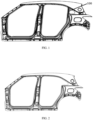
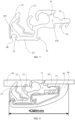
- vehicle body sheet metal 5 with a C-pillar structure 100 is as shown in FIG. 1
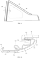
- vehicle body sheet metal without a C-pillar is as shown in FIG. 2
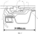
- a sealing structure in the prior art is as shown in FIG. 3 and applied to vehicle body sheet metal with a C-pillar; wherein a sealing strip includes a first part 2 and a second part 3, the first part 2 is not connected with the second part 3; the first part 2 abuts agains glass 1, and the first part 2 is further connected to an injection molding member 4; the second part 3 also abuts agains the glass 1, and the second part 3 is further snap-fitted with sheet metal 5.
- FIG. 3 it can be known that the sealing structure in the prior art results in that a visible width of a C-pillar is greater than or equal to 100mm, the width is wide, and visual effect is poor.
- the present invention provides a vehicle window sealing strip guide rail and a vehicle body side triangular window structure.
- the present invention is specifically implemented by the following technical solutions.
- a vehicle window sealing strip guide rail in the embodiment 1 includes: a first clamping trough, wherein the first clamping trough is configured to clamp a sealing strip and comprises a first clamping plate 511, a first connecting plate 521, and a second clamping plate 512, the first clamping plate 511 is arranged at a first side of the first connecting plate 521, the second clamping plate 512 is arranged at a second side of the first connecting plate 521, the first clamping plate 511 is bent towards a first direction, the second clamping plate 512 is bent towards a second direction, and the first direction is opposite the second direction; and a second clamping trough, wherein the second clamping trough is configured to cooperate with an injection molding member 60 to clamp the sealing strip, and the second clamping trough comprises a second connecting plate 522 and a third connecting plate 523, the second connecting plate 522 is arranged along the first direction, a
- the vehicle window sealing strip guide rail in the embodiment 1 is configured to clamp a sealing strip, and a guide rail 50 can be mounted at a position corresponding to a C-pillar in C-pillar free vehicle body sheet metal. Since there is no sheet metal at the position corresponding to a C-pillar in the C-pillar free vehicle body sheet metal, the embodiment 1 provides a mounting point for the sealing strip by the guide rail 50, so that the sealing strip can be mounted to the position corresponding to a C-pillar in the C-pillar free vehicle body sheet metal, and it is not necessary to make the sealing strip be connected to the sheet metal. Based on FIG. 6 , it can be known that after using the guide rail 50 in the embodiment 1, a visible C-pillar width is less than or equal to 50mm, the width is small, and the visual effect is good.
- FIG. 13 an effect view of a visible region of a vehicle using vehicle body sheet metal with a C-pillar structure is as shown in FIG. 13 .
- FIG. 14 an effect view of a visible region of a vehicle at a position corresponding to a C-pillar is as shown in FIG. 14 .
- the embodiment 1 achieves not only effect of reducing a width of a C-pillar and increasing a visible region of a triangular window, but also effect of simplifying a final assembly process and reducing cost.
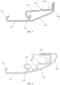
- the sealing strip can include a first stop portion 11, a second stop portion 12, a third stop portion 13, a first clamping portion 11, and a second clamping portion 22; the first stop portion 11, the second stop portion 12, and the third stop portion 13 are all configured to abut against vehicle window glass; the first stop portion 11 is connected to the second stop portion 12, the first clamping portion 21 is connected to the first stop portion 11, and the first clamping portion 21 is configured to be connected to the injection molding member 60 and the guide rail 50; the second clamping portion 22 is respectively connected to the second stop portion 12 and the third stop portion 13, the second clamping portion 22 is configured to be snap-fitted with the guide rail 50, and the first stop portion 11 is further configured to abut against the guide rail 50.
- a first side of the second clamping portion 22 is provided with a first bump 31
- a second side of the second clamping portion 22 is provided with a second bump 32
- the first side of the second clamping portion 22 and the second side of the second clamping portion 22 are arranged oppositely, and the first bump 31 and the second bump 32 are respectively configured to be snap-fitted with the guide rail 50.
- the second clamping portion 22 is snap-fitted with the guide rail 50 through the first bump 31 and the second bump 32.
- the first side of the second clamping portion 22 is further provided with a recess groove 40, the recess groove 40 is configured to receive an end of the guide rail 50.
- the first bump 31 is snap-fitted with the end of the guide rail 50. After the first bump 31 is snap-fitted with the end of the guide rail 50, the end of the guide rail 50 can be received in the recess groove 40, thereby avoiding position interference between the sealing strip and the guide rail 50.
- the included angle A between the third connecting plate 523 and the second connecting plate 522 has an angle range of 90° ⁇ 120°.
- the angle range of the included angle A is adapted to the first clamping portion 21 of the sealing strip, 90° ⁇ the included angle ⁇ 120°.
- the second connecting plate 522 is provided with a protrusion 520 configured to stop the sealing strip.
- the first clamping portion 21 of the sealing strip is provided with a third bump 33, the third bump 33 is configured to be snap-fitted with the guide rail 50.
- the first clamping portion 21 is snap-fitted with the protrusion 520 through the third bump 33, so as to further clamp the first clamping portion 21 to the guide rail 50.
- a hardness of the second stop portion 12, a hardness of the third stop portion 13, and a hardness of the third bump 33 are all less than a hardness of the first clamping portion 21 and a hardness of the second clamping portion 22.
- the second stop portion 12, the third stop portion 13, and the third bump 33 are made of soft glue, and the first clamping portion 21 and the second clamping portion 22 are made of hard glue.
- both the first stop portion 11 and the third stop portion 13 are provided with anti-shrinkage fiberglass 110.
- the guide rail 50 further includes a fourth connecting plate 524, a first side of the fourth connecting plate 524 is connected to a second side of the third connecting plate 523, a second side of the fourth connecting plate 524 abuts against the second clamping plate 512, the second side of the second connecting plate 522 abuts against the fourth connecting plate 524, and the fourth connecting plate 524 is connected to the injection molding member 60.
- the guide rail 50 is connected to the injection molding member 60 through the fourth connecting plate 524.
- the first clamping trough is also connected to the injection molding member 60 to further achieve firm connection between the guide rail 50 and the injection molding member 60.
- the guide rail 50 further includes a U-shaped plate 525, two sides of the opening of the U-shaped plate 525 are respectively provided with a first end portion and a second end portion, the second side of the third connecting plate 523 is bent towards the second direction and connected to the first end portion, and the second side of the fourth connecting plate 524 is bent towards the second direction and connected to the second end portion; the U-shaped plate 525 is configured to be connected to the injection molding member 60.
- the U-shaped plate 525 can be added between the third connecting plate 523 and the fourth connecting plate 524, the U-shaped plate 525 can be connected to the injection molding member 60, so as to increase a connection area between the guide rail 50 and the injection molding member 60 and improve connection firmness.
- being bent towards the first direction is being bent to the right side in the drawings, and being bent towards the second direction is being bent to the left side in the drawings.
- the second connecting plate 522 is provided with a recess portion 530, the recess portion 530 abuts against the fourth connecting plate 524, and the recess portion 530 is located between the first side of the second connecting plate 522 and the protrusion 520.
- the arrangement of the recess portion 530 can reduce hollow cavity between the second connecting plate 522 and the fourth connecting plate 524, improve a structural strength of the guide rail 50, and make the guide rail 50 be less susceptible to damage.
- the guide rail 50 is a roller forming guide rail 50.
- the guide rail 50 in the embodiment 1 is a roller forming guide rail 50, and can effectively lower cost and improve strength.
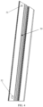
- a first end of the first connecting plate 521 is provided with a circular hole 51, and a second end of the first connecting plate 521 is provided with a strip hole 52; a length direction of the strip hole 52 is the same as a length direction of the first connecting plate 521.
- the guide rail 50 is mounted to vehicle body sheet metal through the circular hole 51 and the strip hole. It is possible to first position and mount the guide rail 50 to the vehicle body sheet metal by a position screw bolt and the circular hole 51, and further fix the guide rail 50 the vehicle body sheet metal by the strip hole and another position screw bolt.
- the present invention adopts a scheme removing C-pillar sheet metal and interior panel and integrating a metal guide rail 50 on a vehicle body side triangular window, thereby solving the problem in the prior art that a C-pillar width is wide and a visible region of a triangular window is small.
- the embodiment 2 provides a vehicle body side triangular window structure, which includes an injection molding member 60, a sealing strip, C-pillar triangular window glass 70, and a window sealing strip guide rail of the embodiment 1, wherein the injection molding member 60 is respectively connected to the guide rail 50 and the C-pillar triangular window glass 70, and the sealing strip is clamped in the guide rail 50.
- the embodiment 2 is applied to vehicle body sheet metal without a C-pillar.
- the guide rail 50 is connected to the C-pillar triangular window glass 70 through the injection molding member 60, and the sealing strip only needs to be mounted to the guide rail 50, it is conducive to mount the sealing strip, and the sealing strip at a C-pillar position needs not to be connected to sheet metal, so that a visible C-pillar width reduces to be less than or equal to 50mm, the width is small, and the visual effect is good.
- the embodiment 1 achieves not only effect of reducing a width of a C-pillar and increasing a visible region of a triangular window, but also effect of simplifying a final assembly process and reducing cost. Cost of a vehicle body side triangular window without a C-pillar is reduced, and detachability and maintenance performance of the triangular window are improved.
- the C-pillar triangular window glass 70 is provided with a first side, a second side, a third side, and an included angle A portion; the included angle A portion is arranged between the second side of the C-pillar triangular window glass 70 and the third side of the C-pillar triangular window glass 70; the guide rail 50 is located at the first side of the C-pillar triangular window glass 70; the vehicle body side triangular window structure further comprises connecting members 40, a plurality of connecting members 40 are respectively located at the second side of the C-pillar triangular window glass 70, the third side of the C-pillar triangular window glass 70, and the included angle A portion; the connecting member 40 comprises a base 41 and a screw bolt 42, the base 41 is connected to the injection molding member 60, the screw bolt 42 is arranged on the base 41, and the screw bolt 42 is configured to be connected to vehicle body sheet metal.
- Adopting the screw bolt 42 to mount can improve mounting accuracy and firmness.
- the injection molding member 60 is connected with the base 41 and the injection molding member 60 passes through a through hole 43 of the base 41, thereby achieving firmness connection between the injection molding member 60 and the connecting member 40.
- the screw bolt 42 of the triangular window assembly is mounted to a mounting positioning hole of side wall sheet metal, thereby effectively improving mounting accuracy and firmness.
- the triangular window comes with butyl glue 30, the butyl glue 30 is arranged on the injection molding member 60.
- the butyl glue 30 is sealing glue and comes with the triangular window. Therefore, in the embodiment 2, there is no need to apply glue on a final assembly line, production efficiency of final assembly glue coating installation is improved, and final assembly cost is lowered, assembly is convenient and quick.
- the vehicle body side triangular window structure of the present invention adds three modules: the C-pillar roller forming guide rail 50, the butyl glue 30, and the connecting member 40.
- the C-pillar guide rail 50 replaces side wall C-pillar sheet metal and interior panels, a visible C-pillar width reduces from 100mm to less than 50mm, an area of a visible region of triangular window glass is increased.
- the butyl glue 30 is sealing glue and comes with the triangular window, the final assembly line needs not coat glue and can be directly assembled, thereby improving final assembly production efficiency.
- the connecting member 40 is a fastening device for the triangular window, and effectively improves accuracy and firmness of assembly of the triangular window. Adopting sticker for sealing and the screw bolt 42 for fixing effectively improves detachability and maintenance performance.
- the present invention provides a vehicle body side triangular window having no C-pillar and coming with glue, which reduces a width of a C-pillar, increases an area of a visible region, and improve effect of the whole vehicle. Adopting its own butyl glue 30 simplifies a final assembly process and improves final assembly efficiency. Assembly using the integrated screw bolt 42 also increase accuracy and stability of mounting the triangular window.
- the present invention has various excellent performances, which include advantages such as improving perception of the whole vehicle, simple assembly, low cost, good C-pillar strength, easy platformization, and so on, and has sufficient adaptability conditions for platform strategies with obvious trend.
Landscapes
- Engineering & Computer Science (AREA)
- Mechanical Engineering (AREA)
- Window Of Vehicle (AREA)
Abstract
Description
- The present invention relates to the field of vehicle structures, and in particular, to a vehicle window sealing strip guide rail and a vehicle body side trianglular window structure.
- In the prior art, side triangle windows of vehicle bodies are fixed with side wall sheet metal and sealed by circumferential sealant. It is necessary to go through a glue coating process on a final assembly line, production efficiency is low and cost is high, and it is difficult to disassemble and repair corner windows after assembly. The side wall sheet metal is equipped with C-pillar sheet metal and its inner side is equipped with a C-pillar interior panel, which makes a C-pillar width be very wide and thus greatly reduces an area of a visible region of a triangle window, the overall effect of a vehicle is affected.
- Side wall sheet metal of most vehicle models in the current market has complete C-pillars, of which outer sides are covered by black edges of corner windows, inner sides are equipped with interior panels, and widths are generally over 100mm. In the vehicle models of which side wall sheet metal has complete C-pillars, the C-pillars are very wide, visible regions of triangular windows are reduced, and visual effect is affected.
- In addition, some frameless vehicle models on the market use C-pillar free triangular windows; for example, Volkswagen Cc and Lamborghini URUS use aluminum alloy guide rails integrated with corner window glass, wherein cost is high, and use final assembly gluing process, wherein production efficiency is low. Although the currently used C-pillar free triangular window vehicle models have reduced widths of C-pillars, they all use the final assembly gluing assembly process, production efficiency is low; the currently adopted C-pillar free triangular window vehicle models all use aluminum alloy guide rails integrated with triangular window glass, cost is high; and vehicle body side triangle windows of current frameless vehicle models all adopts glass glue to fix sealing strips, detachablility and maintenance performance are poor.
- Therefore, it is necessary to provide a scheme of mounting a sealing strip which increases production efficiency and reduces cost while reducing a width of a C-pillar.
- In order to provide a scheme of mounting a sealing strip which increases production efficiency and reduces cost while reducing a width of a C-pillar, the present invention provides a vehicle window sealing strip guide rail and a vehicle body side triangular window structure. The present invention is specifically implemented by the following technical solutions.
- The present invention provides a vehicle window sealing strip guide rail comprising: a first clamping trough, wherein the first clamping trough is configured to clamp a sealing strip and comprises a first clamping plate, a first connecting plate, and a second clamping plate, the first clamping plate is arranged at a first side of the first connecting plate, the second clamping plate is arranged at a second side of the first connecting plate, the first clamping plate is bent towards a first direction, the second clamping plate is bent towards a second direction, and the first direction is opposite the second direction; and a second clamping trough, wherein the second clamping trough is configured to cooperate with an injection molding member to clamp the sealing strip, and the second clamping trough comprises a second connecting plate and a third connecting plate, the second connecting plate is arranged along the first direction, a first side of the second connecting plate is connected to the second clamping plate, a second side of the second connecting plate is connected to a first side of the third connecting plate, and an included angle is provided between the third connecting plate and the second connecting plate.
- Further improvement of the vehicle window sealing strip guide rail provided by the present invention is that: an angle range of the included angle is 90°~120°.
- Further improvement of the vehicle window sealing strip guide rail provided by the present invention is that: the second connecting plate is provided with a protrusion configured to resist the sealing strip.
- Further improvement of the vehicle window sealing strip guide rail provided by the present invention is that: a fourth connecting plate is further included; a first side of the fourth connecting plate is connected to a second side of the third connecting plate, a second side of the fourth connecting plate abuts against the second clamping plate, the second side of the second connecting plate abuts against the fourth connecting plate, and the fourth connecting plate is configured to be connected to the injection molding member.
- Further improvement of the vehicle window sealing strip guide rail provided by the present invention is that: the second side of the third connecting plate is bent towards the first direction and connected to the first side of the fourth connecting plate, and the third connecting plate abuts against the fourth connecting plate; alternatively, the guide rail further comprises a U-shaped plate, two sides of the opening of the U-shaped plate are respectively provided with a first end portion and a second end portion, the second side of the third connecting plate is bent towards the second direction and connected to the first end portion, and the second side of the fourth connecting plate is bent towards the second direction and connected to the second end portion; the U-shaped plate is configured to be connected to the injection molding member.
- Further improvement of the vehicle window sealing strip guide rail provided by the present invention is that: the second connecting plate is provided with a recess portion, the recess portion abuts against the fourth connecting plate, and the recess portion is located between the first side and the protrusion of the second connecting plate.
- Further improvement of the vehicle window sealing strip guide rail provided by the present invention is that: the guide rail is a roller forming guide rail.
- Further improvement of the vehicle window sealing strip guide rail provided by the present invention is that: a first end of the first connecting plate is provided with a circular hole, a second end of the first connecting plate is provided with a strip hole, a length direction of the strip hole is the same as a length direction of the first connecting plate.
- Furthermore, the present invention further provides a vehicle body side triangular window structure comprising an injection molding member, a sealing strip, C-pillar triangular window glass, and a window sealing strip guide rail as described above, wherein the injection molding member is respectively connected to the guide rail and the C-pillar triangular window glass, and the sealing strip is clamped in the guide rail.
- Further improvement of the vehicle body side triangular window structure provided by the present invention is that: the C-pillar triangular window glass is provided with a first side, a second side, a third side, and an included angle portion; the included angle portion is arranged between the second side of the C-pillar triangular window glass and the third side of the C-pillar triangular window glass; the guide rail is located at the first side of the C-pillar triangular window glass; the vehicle body side triangular window structure further comprises connecting members, a plurality of connecting members are respectively located at the second side of the C-pillar triangular window glass, the third side of the C-pillar triangular window glass, and the included angle portion; the connecting member comprises a base and a screw bolt, the base is connected to the injection molding member, the screw bolt is arranged on the base, and the screw bolt is configured to be connected to vehicle body sheet metal.
- The vehicle window sealing strip guide rail provided by the present invention is configured to clamp a sealing strip, and the guide rail can be mounted at a position corresponding to a C-pillar in C-pillar free vehicle body sheet metal. Since there is no sheet metal at the position corresponding to a C-pillar in the C-pillar free vehicle body sheet metal, the present invention provides a mounting point for the sealing strip by the guide rail, so that the sealing strip can be mounted to the position corresponding to a C-pillar in the C-pillar free vehicle body sheet metal, and it is not necessary to make the sealing strip be connected to the sheet metal. After using the guide rail of the present invention, a visible C-pillar width is less than or equal to 50mm, the width is small, and the visual effect is good.
- In order to explain technical solutions of embodiments of the present invention or in the prior art more clearly, drawings required to be used in description of the embodiments or of the prior art will be briefly introduced below. It is obvious that the drawings in the following description are only some embodiments of the present invention. For those skilled in the art, other drawings can be further obtained according to these drawings on the premise of paying no creative work.
-
FIG. 1 is a structural schematic view of vehicle body sheet metal with a C-pillar in the prior art. -
FIG. 2 is a structural schematic view of vehicle body sheet metal without a C-pillar in the prior art. -
FIG. 3 is a schematic view of a connecting structure among a sealing strip, vehicle window glass, an injection molding member, and sheet metal in the prior art. -
FIG. 4 is a structural schematic view of a vehicle window sealing strip guide rail provided by anembodiment 1. -
FIG. 5 is a cross-sectional structural schematic view of the vehicle window sealing strip guide rail provided by theembodiment 1. -
FIG. 6 is another cross-sectional structural schematic view of the vehicle window sealing strip guide rail provided by theembodiment 1. -
FIG. 7 is a structural schematic view of a sealing strip. -
FIG. 8 is a schematic view of a connecting structure among a sealing strip, a guide rail, vehicle window glass, and an injection molding member. -
FIG. 9 is a schematic front view of a vehicle body side triangular window structure provided by anembodiment 2. -
FIG. 10 is a cross-sectional schematic view along A-A inFIG. 9 . -
FIG. 11 is a schematic rear view of the vehicle body side triangular window structure provided by theembodiment 2. -
FIG. 12 is a structural schematic view of a connecting member of theembodiment 2. -
FIG. 13 is an effect view of a visible region of a vehicle using vehicle body sheet metal with a C-pillar structure. -
FIG. 14 is an effect view of a visible region of a vehicle using vehicle body sheet metal without a C-pillar structure. - The technical solutions in the embodiments of the present invention will be described clearly and completely below in combination with the drawings in the embodiments of the present invention. Obviously, the described embodiments are merely some embodiments of the present invention, rather than all embodiments. Based on the embodiments of the present invention, any other embodiment obtained by one of ordinary skill in the art on the premise of paying no creative work belongs to the protection scope of the present invention.
- In the prior art, vehicle
body sheet metal 5 with a C-pillar structure 100 is as shown inFIG. 1 , and vehicle body sheet metal without a C-pillar is as shown inFIG. 2 . A sealing structure in the prior art is as shown inFIG. 3 and applied to vehicle body sheet metal with a C-pillar; wherein a sealing strip includes afirst part 2 and asecond part 3, thefirst part 2 is not connected with thesecond part 3; thefirst part 2 abuts againsglass 1, and thefirst part 2 is further connected to aninjection molding member 4; thesecond part 3 also abuts agains theglass 1, and thesecond part 3 is further snap-fitted withsheet metal 5. Based onFIG. 3 , it can be known that the sealing structure in the prior art results in that a visible width of a C-pillar is greater than or equal to 100mm, the width is wide, and visual effect is poor. - In order to provide a scheme of mounting a sealing strip which increases production efficiency and reduces cost while reducing a width of a C-pillar, the present invention provides a vehicle window sealing strip guide rail and a vehicle body side triangular window structure. The present invention is specifically implemented by the following technical solutions.
- In combination with the shown in
FIG. 4 to FIG.9 ,FIG. 13, and FIG. 14 , a vehicle window sealing strip guide rail in theembodiment 1 includes: a first clamping trough, wherein the first clamping trough is configured to clamp a sealing strip and comprises afirst clamping plate 511, a first connectingplate 521, and asecond clamping plate 512, thefirst clamping plate 511 is arranged at a first side of the first connectingplate 521, thesecond clamping plate 512 is arranged at a second side of the first connectingplate 521, thefirst clamping plate 511 is bent towards a first direction, thesecond clamping plate 512 is bent towards a second direction, and the first direction is opposite the second direction; and a second clamping trough, wherein the second clamping trough is configured to cooperate with aninjection molding member 60 to clamp the sealing strip, and the second clamping trough comprises a second connectingplate 522 and a third connectingplate 523, the second connectingplate 522 is arranged along the first direction, a first side of the second connectingplate 522 is connected to thesecond clamping plate 512, a second side of the second connectingplate 522 is connected to a first side of the third connectingplate 523, and an included angle A is provided between the third connectingplate 523 and the second connectingplate 522. - The vehicle window sealing strip guide rail in the
embodiment 1 is configured to clamp a sealing strip, and aguide rail 50 can be mounted at a position corresponding to a C-pillar in C-pillar free vehicle body sheet metal. Since there is no sheet metal at the position corresponding to a C-pillar in the C-pillar free vehicle body sheet metal, theembodiment 1 provides a mounting point for the sealing strip by theguide rail 50, so that the sealing strip can be mounted to the position corresponding to a C-pillar in the C-pillar free vehicle body sheet metal, and it is not necessary to make the sealing strip be connected to the sheet metal. Based onFIG. 6 , it can be known that after using theguide rail 50 in theembodiment 1, a visible C-pillar width is less than or equal to 50mm, the width is small, and the visual effect is good. - In the prior art, an effect view of a visible region of a vehicle using vehicle body sheet metal with a C-pillar structure is as shown in
FIG. 13 . When applying theembodiment 1 in vehicle body sheet metal without a C-pillar structure, an effect view of a visible region of a vehicle at a position corresponding to a C-pillar is as shown inFIG. 14 . Based on comparison betweenFIG. 13 and FIG. 14 , it can be known that after using theembodiment 1, an area of a visible region can be obviously increased, and visual effect of the visible region is optimized. - The
embodiment 1 achieves not only effect of reducing a width of a C-pillar and increasing a visible region of a triangular window, but also effect of simplifying a final assembly process and reducing cost. - The sealing strip can include a
first stop portion 11, asecond stop portion 12, athird stop portion 13, afirst clamping portion 11, and asecond clamping portion 22; thefirst stop portion 11, thesecond stop portion 12, and thethird stop portion 13 are all configured to abut against vehicle window glass; thefirst stop portion 11 is connected to thesecond stop portion 12, thefirst clamping portion 21 is connected to thefirst stop portion 11, and thefirst clamping portion 21 is configured to be connected to theinjection molding member 60 and theguide rail 50; thesecond clamping portion 22 is respectively connected to thesecond stop portion 12 and thethird stop portion 13, thesecond clamping portion 22 is configured to be snap-fitted with theguide rail 50, and thefirst stop portion 11 is further configured to abut against theguide rail 50. - Furthermore, a first side of the
second clamping portion 22 is provided with afirst bump 31, a second side of thesecond clamping portion 22 is provided with asecond bump 32, the first side of thesecond clamping portion 22 and the second side of thesecond clamping portion 22 are arranged oppositely, and thefirst bump 31 and thesecond bump 32 are respectively configured to be snap-fitted with theguide rail 50. In theembodiment 1, thesecond clamping portion 22 is snap-fitted with theguide rail 50 through thefirst bump 31 and thesecond bump 32. - Furthermore, the first side of the
second clamping portion 22 is further provided with arecess groove 40, therecess groove 40 is configured to receive an end of theguide rail 50. In theembodiment 1, thefirst bump 31 is snap-fitted with the end of theguide rail 50. After thefirst bump 31 is snap-fitted with the end of theguide rail 50, the end of theguide rail 50 can be received in therecess groove 40, thereby avoiding position interference between the sealing strip and theguide rail 50. - Furthermore, the included angle A between the third connecting
plate 523 and the second connectingplate 522 has an angle range of 90°~120°. In theembodiment 1, the angle range of the included angle A is adapted to thefirst clamping portion 21 of the sealing strip, 90°<the included angle≤120°. - Furthermore, the second connecting
plate 522 is provided with aprotrusion 520 configured to stop the sealing strip. Furthermore, thefirst clamping portion 21 of the sealing strip is provided with athird bump 33, thethird bump 33 is configured to be snap-fitted with theguide rail 50. In theembodiment 1, thefirst clamping portion 21 is snap-fitted with theprotrusion 520 through thethird bump 33, so as to further clamp thefirst clamping portion 21 to theguide rail 50. - In the
embodiment 1, a hardness of thesecond stop portion 12, a hardness of thethird stop portion 13, and a hardness of thethird bump 33 are all less than a hardness of thefirst clamping portion 21 and a hardness of thesecond clamping portion 22. Thesecond stop portion 12, thethird stop portion 13, and thethird bump 33 are made of soft glue, and thefirst clamping portion 21 and thesecond clamping portion 22 are made of hard glue. In theembodiment 1, both thefirst stop portion 11 and thethird stop portion 13 are provided withanti-shrinkage fiberglass 110. - Furthermore, the
guide rail 50 further includes a fourth connectingplate 524, a first side of the fourth connectingplate 524 is connected to a second side of the third connectingplate 523, a second side of the fourth connectingplate 524 abuts against thesecond clamping plate 512, the second side of the second connectingplate 522 abuts against the fourth connectingplate 524, and the fourth connectingplate 524 is connected to theinjection molding member 60. - In the
embodiment 1, theguide rail 50 is connected to theinjection molding member 60 through the fourth connectingplate 524. Preferably, the first clamping trough is also connected to theinjection molding member 60 to further achieve firm connection between theguide rail 50 and theinjection molding member 60. - Furthermore, the second side of the third connecting
plate 523 is bent towards the first direction and connected to the first side of the fourth connectingplate 524, and the third connectingplate 523 abuts against the fourth connectingplate 524; alternatively, theguide rail 50 further includes aU-shaped plate 525, two sides of the opening of theU-shaped plate 525 are respectively provided with a first end portion and a second end portion, the second side of the third connectingplate 523 is bent towards the second direction and connected to the first end portion, and the second side of the fourth connectingplate 524 is bent towards the second direction and connected to the second end portion; theU-shaped plate 525 is configured to be connected to theinjection molding member 60. - In the
embodiment 1, theU-shaped plate 525 can be added between the third connectingplate 523 and the fourth connectingplate 524, theU-shaped plate 525 can be connected to theinjection molding member 60, so as to increase a connection area between theguide rail 50 and theinjection molding member 60 and improve connection firmness. In theembodiment 1, being bent towards the first direction is being bent to the right side in the drawings, and being bent towards the second direction is being bent to the left side in the drawings. - Furthermore, the second connecting
plate 522 is provided with arecess portion 530, therecess portion 530 abuts against the fourth connectingplate 524, and therecess portion 530 is located between the first side of the second connectingplate 522 and theprotrusion 520. - In the
embodiment 1, the arrangement of therecess portion 530 can reduce hollow cavity between the second connectingplate 522 and the fourth connectingplate 524, improve a structural strength of theguide rail 50, and make theguide rail 50 be less susceptible to damage. - Furthermore, the
guide rail 50 is a roller formingguide rail 50. Compared with commonly used aluminumalloy guide rails 50, theguide rail 50 in theembodiment 1 is a roller formingguide rail 50, and can effectively lower cost and improve strength. - Furthermore, a first end of the first connecting
plate 521 is provided with acircular hole 51, and a second end of the first connectingplate 521 is provided with astrip hole 52; a length direction of thestrip hole 52 is the same as a length direction of the first connectingplate 521. - In the
embodiment 1, theguide rail 50 is mounted to vehicle body sheet metal through thecircular hole 51 and the strip hole. It is possible to first position and mount theguide rail 50 to the vehicle body sheet metal by a position screw bolt and thecircular hole 51, and further fix theguide rail 50 the vehicle body sheet metal by the strip hole and another position screw bolt. - The present invention adopts a scheme removing C-pillar sheet metal and interior panel and integrating a
metal guide rail 50 on a vehicle body side triangular window, thereby solving the problem in the prior art that a C-pillar width is wide and a visible region of a triangular window is small. - In combination with the shown in
FIG. 10 to FIG. 12 , theembodiment 2 provides a vehicle body side triangular window structure, which includes aninjection molding member 60, a sealing strip, C-pillartriangular window glass 70, and a window sealing strip guide rail of theembodiment 1, wherein theinjection molding member 60 is respectively connected to theguide rail 50 and the C-pillartriangular window glass 70, and the sealing strip is clamped in theguide rail 50. - The
embodiment 2 is applied to vehicle body sheet metal without a C-pillar. Theguide rail 50 is connected to the C-pillartriangular window glass 70 through theinjection molding member 60, and the sealing strip only needs to be mounted to theguide rail 50, it is conducive to mount the sealing strip, and the sealing strip at a C-pillar position needs not to be connected to sheet metal, so that a visible C-pillar width reduces to be less than or equal to 50mm, the width is small, and the visual effect is good. - The
embodiment 1 achieves not only effect of reducing a width of a C-pillar and increasing a visible region of a triangular window, but also effect of simplifying a final assembly process and reducing cost. Cost of a vehicle body side triangular window without a C-pillar is reduced, and detachability and maintenance performance of the triangular window are improved. - Furthermore, the C-pillar
triangular window glass 70 is provided with a first side, a second side, a third side, and an included angle A portion; the included angle A portion is arranged between the second side of the C-pillartriangular window glass 70 and the third side of the C-pillartriangular window glass 70; theguide rail 50 is located at the first side of the C-pillartriangular window glass 70; the vehicle body side triangular window structure further comprises connectingmembers 40, a plurality of connectingmembers 40 are respectively located at the second side of the C-pillartriangular window glass 70, the third side of the C-pillartriangular window glass 70, and the included angle A portion; the connectingmember 40 comprises abase 41 and ascrew bolt 42, thebase 41 is connected to theinjection molding member 60, thescrew bolt 42 is arranged on thebase 41, and thescrew bolt 42 is configured to be connected to vehicle body sheet metal. Adopting thescrew bolt 42 to mount can improve mounting accuracy and firmness. Theinjection molding member 60 is connected with thebase 41 and theinjection molding member 60 passes through a throughhole 43 of thebase 41, thereby achieving firmness connection between theinjection molding member 60 and the connectingmember 40. - The
screw bolt 42 of the triangular window assembly is mounted to a mounting positioning hole of side wall sheet metal, thereby effectively improving mounting accuracy and firmness. - Furthermore, the triangular window comes with
butyl glue 30, thebutyl glue 30 is arranged on theinjection molding member 60. Thebutyl glue 30 is sealing glue and comes with the triangular window. Therefore, in theembodiment 2, there is no need to apply glue on a final assembly line, production efficiency of final assembly glue coating installation is improved, and final assembly cost is lowered, assembly is convenient and quick. - The vehicle body side triangular window structure of the present invention adds three modules: the C-pillar roller forming
guide rail 50, thebutyl glue 30, and the connectingmember 40. Among them, the C-pillar guide rail 50 replaces side wall C-pillar sheet metal and interior panels, a visible C-pillar width reduces from 100mm to less than 50mm, an area of a visible region of triangular window glass is increased. Thebutyl glue 30 is sealing glue and comes with the triangular window, the final assembly line needs not coat glue and can be directly assembled, thereby improving final assembly production efficiency. The connectingmember 40 is a fastening device for the triangular window, and effectively improves accuracy and firmness of assembly of the triangular window. Adopting sticker for sealing and thescrew bolt 42 for fixing effectively improves detachability and maintenance performance. - The present invention provides a vehicle body side triangular window having no C-pillar and coming with glue, which reduces a width of a C-pillar, increases an area of a visible region, and improve effect of the whole vehicle. Adopting its
own butyl glue 30 simplifies a final assembly process and improves final assembly efficiency. Assembly using theintegrated screw bolt 42 also increase accuracy and stability of mounting the triangular window. The present invention has various excellent performances, which include advantages such as improving perception of the whole vehicle, simple assembly, low cost, good C-pillar strength, easy platformization, and so on, and has sufficient adaptability conditions for platform strategies with obvious trend. - The above are only preferred embodiments of the present invention, and are not intended to limit the present invention. Any modification, equivalent replacement, and improvement made within the spirit and principles of the present invention should be included in the protection scope of the present invention.
Claims (10)
- A vehicle window sealing strip guide rail comprising: a first clamping trough, wherein the first clamping trough is configured to clamp a sealing strip and comprises a first clamping plate (511), a first connecting plate (521), and a second clamping plate (512), the first clamping plate (511) is arranged at a first side of the first connecting plate (521), the second clamping plate (512) is arranged at a second side of the first connecting plate (521), the first clamping plate (511) is bent towards a first direction, the second clamping plate (512) is bent towards a second direction, and the first direction is opposite the second direction; and a second clamping trough, wherein the second clamping trough is configured to cooperate with an injection molding member (60) to clamp the sealing strip, and the second clamping trough comprises a second connecting plate (522) and a third connecting plate (523), the second connecting plate (522) is arranged along the first direction, a first side of the second connecting plate (522) is connected to the second clamping plate (512), a second side of the second connecting plate (522) is connected to a first side of the third connecting plate (523), and an included angle (A) is provided between the third connecting plate (523) and the second connecting plate (522).
- The vehicle window sealing strip guide rail according to claim 1, wherein an angle range of the included angle (A) is 90°~120°.
- The vehicle window sealing strip guide rail according to claim 1, wherein the second connecting plate (522) is provided with a protrusion (520) configured to resist the sealing strip.
- The vehicle window sealing strip guide rail according to claim 3, further comprising a fourth connecting plate (524); wherein a first side of the fourth connecting plate (524) is connected to a second side of the third connecting plate (523), a second side of the fourth connecting plate (524) abuts against the second clamping plate (512), the second side of the second connecting plate (522) abuts against the fourth connecting plate (524), and the fourth connecting plate (524) is configured to be connected to the injection molding member (60).
- The vehicle window sealing strip guide rail according to claim 4, wherein the second side of the third connecting plate (523) is bent towards the first direction and connected to the first side of the fourth connecting plate (524), and the third connecting plate (523) abuts against the fourth connecting plate (524); alternatively, the guide rail further comprises a U-shaped plate (525), two sides of the opening of the U-shaped plate (525) are respectively provided with a first end portion and a second end portion, the second side of the third connecting plate (523) is bent towards the second direction and connected to the first end portion, and the second side of the fourth connecting plate (524) is bent towards the second direction and connected to the second end portion; the U-shaped plate (525) is configured to be connected to the injection molding member (60).
- The vehicle window sealing strip guide rail according to claim 5, wherein the second connecting plate (522) is provided with a recess portion (530), the recess portion (530) abuts against the fourth connecting plate (524), and the recess portion (530) is located between the first side and the protrusion (520) of the second connecting plate (522).
- The vehicle window sealing strip guide rail according to claim 1, wherein the guide rail is a roller forming guide rail.
- The vehicle window sealing strip guide rail according to claim 1, wherein a first end of the first connecting plate (521) is provided with a circular hole (51), a second end of the first connecting plate (521) is provided with a strip hole (52), a length direction of the strip hole (52) is the same as a length direction of the first connecting plate (521).
- A vehicle body side triangular window structure comprising an injection molding member (60), a sealing strip, C-pillar triangular window glass (70), and a window sealing strip guide rail (50) according to any one of claims 1-8, wherein the injection molding member (60) is respectively connected to the guide rail (50) and the C-pillar triangular window glass (70), and the sealing strip is clamped in the guide rail (50).
- The vehicle body side triangular window structure according to claim 9, wherein the C-pillar triangular window glass (70) is provided with a first side, a second side, a third side, and an included angle portion; the included angle portion is arranged between the second side of the C-pillar triangular window glass (70) and the third side of the C-pillar triangular window glass (70); the guide rail (50) is located at the first side of the C-pillar triangular window glass (70); the vehicle body side triangular window structure further comprises connecting members (40), a plurality of connecting members (40) are respectively located at the second side of the C-pillar triangular window glass (70), the third side of the C-pillar triangular window glass (70), and the included angle portion; the connecting member (40) comprises a base (41) and a screw bolt (42), the base (41) is connected to the injection molding member (60), the screw bolt (42) is arranged on the base (41), and the screw bolt (42) is configured to be connected to vehicle body sheet metal.
Applications Claiming Priority (1)
| Application Number | Priority Date | Filing Date | Title |
|---|---|---|---|
| PCT/CN2021/073986 WO2022160130A1 (en) | 2021-01-27 | 2021-01-27 | Vehicle window sealing strip guide rail and vehicle body side triangular window structure |
Publications (1)
| Publication Number | Publication Date |
|---|---|
| EP4286186A1 true EP4286186A1 (en) | 2023-12-06 |
Family
ID=82654010
Family Applications (1)
| Application Number | Title | Priority Date | Filing Date |
|---|---|---|---|
| EP21921750.2A Pending EP4286186A1 (en) | 2021-01-27 | 2021-01-27 | Vehicle window sealing strip guide rail and vehicle body side triangular window structure |
Country Status (3)
| Country | Link |
|---|---|
| EP (1) | EP4286186A1 (en) |
| CN (1) | CN116635260B (en) |
| WO (1) | WO2022160130A1 (en) |
Family Cites Families (7)
| Publication number | Priority date | Publication date | Assignee | Title |
|---|---|---|---|---|
| DE20304785U1 (en) * | 2003-03-25 | 2004-07-29 | Raico Bautechnik Gmbh | Glass wing, especially for a door or window, comprises at least two glass plates separated via a distance strip and a holding section with an insulating part |
| CN203344718U (en) * | 2013-06-14 | 2013-12-18 | 北京汽车股份有限公司 | Glass guiding groove sealing strip and vehicle door |
| CN103481755A (en) * | 2013-09-29 | 2014-01-01 | 贵州大学 | Automobile window sealing device |
| DE102014105518A1 (en) * | 2014-04-17 | 2015-10-22 | Cqlt Saargummi Technologies S.À.R.L. | Vehicle body seal with trim strip |
| CN205327175U (en) * | 2015-12-30 | 2016-06-22 | 上海卡豹汽车科技有限公司 | Installation pipe of car body structure post and car that has this installation pipe |
| US10457129B2 (en) * | 2017-04-11 | 2019-10-29 | Bestop, Inc. | Multi configurable half top assembly |
| CN111002801B (en) * | 2019-12-30 | 2021-08-13 | 神龙汽车有限公司 | Automobile flush door structure |
-
2021
- 2021-01-27 EP EP21921750.2A patent/EP4286186A1/en active Pending
- 2021-01-27 WO PCT/CN2021/073986 patent/WO2022160130A1/en active Application Filing
- 2021-01-27 CN CN202180082253.6A patent/CN116635260B/en active Active
Also Published As
| Publication number | Publication date |
|---|---|
| CN116635260A (en) | 2023-08-22 |
| WO2022160130A1 (en) | 2022-08-04 |
| CN116635260B (en) | 2024-06-11 |
Similar Documents
| Publication | Publication Date | Title |
|---|---|---|
| CN108316810B (en) | Door and window system | |
| EP4286186A1 (en) | Vehicle window sealing strip guide rail and vehicle body side triangular window structure | |
| CN112026932A (en) | Car plastics roof side rail mounting structure and electric automobile | |
| CN110816234B (en) | Front door and window guide rail sealing strip assembly | |
| CN214189248U (en) | Mounting structure of door glass guide slot | |
| CN210027048U (en) | Elastic clamping structure for front end of instrument board and metal plate of vehicle body | |
| CN210617821U (en) | Novel door and window frame bright wisp structure of car | |
| EP4335673A1 (en) | Triangular window assembly and automobile with same | |
| CN218112327U (en) | Groove mounting structure, door and car | |
| EP4286187A1 (en) | Sealing strip structure and sealing device | |
| CN221113486U (en) | Sealing structure of door corner window and vehicle | |
| CN216969549U (en) | Front door outer water splitting strip with bright strip | |
| CN219927439U (en) | Glass guide groove | |
| CN220226611U (en) | Quick-mounting type fixed glass mounting structure | |
| CN219650983U (en) | Skylight guide rail | |
| CN211058574U (en) | Special door and window waterproof closing part for light steel house | |
| CN217514946U (en) | Flush type rubber strip structure integrated with front corner window glass | |
| CN219382187U (en) | Door frame sealing strip structure | |
| CN219947874U (en) | Vehicle door assembly and vehicle comprising same | |
| CN219727841U (en) | Tail door dustproof strip | |
| CN216886221U (en) | Seal structure and vehicle of frameless door | |
| CN215520586U (en) | Installation fixed knot of many curved surfaces energy-conserving window constructs | |
| CN216507824U (en) | Automobile door triangular window assembly | |
| CN210577200U (en) | Block terminal convenient to assembly and maintenance use | |
| CN217151728U (en) | Glass pressing line for casement parallel and level |
Legal Events
| Date | Code | Title | Description |
|---|---|---|---|
| STAA | Information on the status of an ep patent application or granted ep patent |
Free format text: STATUS: THE INTERNATIONAL PUBLICATION HAS BEEN MADE |
|
| PUAI | Public reference made under article 153(3) epc to a published international application that has entered the european phase |
Free format text: ORIGINAL CODE: 0009012 |
|
| STAA | Information on the status of an ep patent application or granted ep patent |
Free format text: STATUS: REQUEST FOR EXAMINATION WAS MADE |
|
| 17P | Request for examination filed |
Effective date: 20230714 |
|
| AK | Designated contracting states |
Kind code of ref document: A1 Designated state(s): AL AT BE BG CH CY CZ DE DK EE ES FI FR GB GR HR HU IE IS IT LI LT LU LV MC MK MT NL NO PL PT RO RS SE SI SK SM TR |
|
| DAV | Request for validation of the european patent (deleted) | ||
| DAX | Request for extension of the european patent (deleted) | ||
| REG | Reference to a national code |
Ref country code: DE Ref legal event code: R079 Free format text: PREVIOUS MAIN CLASS: B60J0010760000 Ipc: B60J0010300000 |