EP4286151B1 - Gekrümmte wand mit abwechselnden metall- und verbundschichten und verfahren zu ihrer herstellung - Google Patents
Gekrümmte wand mit abwechselnden metall- und verbundschichten und verfahren zu ihrer herstellung Download PDFInfo
- Publication number
- EP4286151B1 EP4286151B1 EP22177045.6A EP22177045A EP4286151B1 EP 4286151 B1 EP4286151 B1 EP 4286151B1 EP 22177045 A EP22177045 A EP 22177045A EP 4286151 B1 EP4286151 B1 EP 4286151B1
- Authority
- EP
- European Patent Office
- Prior art keywords
- metal
- layer
- strips
- curved wall
- composite
- Prior art date
- Legal status (The legal status is an assumption and is not a legal conclusion. Google has not performed a legal analysis and makes no representation as to the accuracy of the status listed.)
- Active
Links
Images

Classifications
-
- B—PERFORMING OPERATIONS; TRANSPORTING
- B32—LAYERED PRODUCTS
- B32B—LAYERED PRODUCTS, i.e. PRODUCTS BUILT-UP OF STRATA OF FLAT OR NON-FLAT, e.g. CELLULAR OR HONEYCOMB, FORM
- B32B3/00—Layered products comprising a layer with external or internal discontinuities or unevennesses, or a layer of non-planar shape; Layered products comprising a layer having particular features of form
- B32B3/10—Layered products comprising a layer with external or internal discontinuities or unevennesses, or a layer of non-planar shape; Layered products comprising a layer having particular features of form characterised by a discontinuous layer, i.e. formed of separate pieces of material
- B32B3/14—Layered products comprising a layer with external or internal discontinuities or unevennesses, or a layer of non-planar shape; Layered products comprising a layer having particular features of form characterised by a discontinuous layer, i.e. formed of separate pieces of material characterised by a face layer formed of separate pieces of material which are juxtaposed side-by-side
-
- B—PERFORMING OPERATIONS; TRANSPORTING
- B32—LAYERED PRODUCTS
- B32B—LAYERED PRODUCTS, i.e. PRODUCTS BUILT-UP OF STRATA OF FLAT OR NON-FLAT, e.g. CELLULAR OR HONEYCOMB, FORM
- B32B1/00—Layered products having a non-planar shape
-
- B—PERFORMING OPERATIONS; TRANSPORTING
- B32—LAYERED PRODUCTS
- B32B—LAYERED PRODUCTS, i.e. PRODUCTS BUILT-UP OF STRATA OF FLAT OR NON-FLAT, e.g. CELLULAR OR HONEYCOMB, FORM
- B32B15/00—Layered products comprising a layer of metal
- B32B15/04—Layered products comprising a layer of metal comprising metal as the main or only constituent of a layer, which is next to another layer of the same or of a different material
- B32B15/08—Layered products comprising a layer of metal comprising metal as the main or only constituent of a layer, which is next to another layer of the same or of a different material of synthetic resin
- B32B15/092—Layered products comprising a layer of metal comprising metal as the main or only constituent of a layer, which is next to another layer of the same or of a different material of synthetic resin comprising epoxy resins
-
- B—PERFORMING OPERATIONS; TRANSPORTING
- B32—LAYERED PRODUCTS
- B32B—LAYERED PRODUCTS, i.e. PRODUCTS BUILT-UP OF STRATA OF FLAT OR NON-FLAT, e.g. CELLULAR OR HONEYCOMB, FORM
- B32B15/00—Layered products comprising a layer of metal
- B32B15/14—Layered products comprising a layer of metal next to a fibrous or filamentary layer
-
- B—PERFORMING OPERATIONS; TRANSPORTING
- B32—LAYERED PRODUCTS
- B32B—LAYERED PRODUCTS, i.e. PRODUCTS BUILT-UP OF STRATA OF FLAT OR NON-FLAT, e.g. CELLULAR OR HONEYCOMB, FORM
- B32B3/00—Layered products comprising a layer with external or internal discontinuities or unevennesses, or a layer of non-planar shape; Layered products comprising a layer having particular features of form
- B32B3/10—Layered products comprising a layer with external or internal discontinuities or unevennesses, or a layer of non-planar shape; Layered products comprising a layer having particular features of form characterised by a discontinuous layer, i.e. formed of separate pieces of material
- B32B3/18—Layered products comprising a layer with external or internal discontinuities or unevennesses, or a layer of non-planar shape; Layered products comprising a layer having particular features of form characterised by a discontinuous layer, i.e. formed of separate pieces of material characterised by an internal layer formed of separate pieces of material which are juxtaposed side-by-side
-
- B—PERFORMING OPERATIONS; TRANSPORTING
- B32—LAYERED PRODUCTS
- B32B—LAYERED PRODUCTS, i.e. PRODUCTS BUILT-UP OF STRATA OF FLAT OR NON-FLAT, e.g. CELLULAR OR HONEYCOMB, FORM
- B32B38/00—Ancillary operations in connection with laminating processes
- B32B38/0036—Heat treatment
-
- B—PERFORMING OPERATIONS; TRANSPORTING
- B32—LAYERED PRODUCTS
- B32B—LAYERED PRODUCTS, i.e. PRODUCTS BUILT-UP OF STRATA OF FLAT OR NON-FLAT, e.g. CELLULAR OR HONEYCOMB, FORM
- B32B5/00—Layered products characterised by the non- homogeneity or physical structure, i.e. comprising a fibrous, filamentary, particulate or foam layer; Layered products characterised by having a layer differing constitutionally or physically in different parts
- B32B5/02—Layered products characterised by the non- homogeneity or physical structure, i.e. comprising a fibrous, filamentary, particulate or foam layer; Layered products characterised by having a layer differing constitutionally or physically in different parts characterised by structural features of a fibrous or filamentary layer
- B32B5/12—Layered products characterised by the non- homogeneity or physical structure, i.e. comprising a fibrous, filamentary, particulate or foam layer; Layered products characterised by having a layer differing constitutionally or physically in different parts characterised by structural features of a fibrous or filamentary layer characterised by the relative arrangement of fibres or filaments of different layers, e.g. the fibres or filaments being parallel or perpendicular to each other
-
- B—PERFORMING OPERATIONS; TRANSPORTING
- B32—LAYERED PRODUCTS
- B32B—LAYERED PRODUCTS, i.e. PRODUCTS BUILT-UP OF STRATA OF FLAT OR NON-FLAT, e.g. CELLULAR OR HONEYCOMB, FORM
- B32B7/00—Layered products characterised by the relation between layers; Layered products characterised by the relative orientation of features between layers, or by the relative values of a measurable parameter between layers, i.e. products comprising layers having different physical, chemical or physicochemical properties; Layered products characterised by the interconnection of layers
- B32B7/03—Layered products characterised by the relation between layers; Layered products characterised by the relative orientation of features between layers, or by the relative values of a measurable parameter between layers, i.e. products comprising layers having different physical, chemical or physicochemical properties; Layered products characterised by the interconnection of layers with respect to the orientation of features
-
- B—PERFORMING OPERATIONS; TRANSPORTING
- B32—LAYERED PRODUCTS
- B32B—LAYERED PRODUCTS, i.e. PRODUCTS BUILT-UP OF STRATA OF FLAT OR NON-FLAT, e.g. CELLULAR OR HONEYCOMB, FORM
- B32B7/00—Layered products characterised by the relation between layers; Layered products characterised by the relative orientation of features between layers, or by the relative values of a measurable parameter between layers, i.e. products comprising layers having different physical, chemical or physicochemical properties; Layered products characterised by the interconnection of layers
- B32B7/04—Interconnection of layers
- B32B7/12—Interconnection of layers using interposed adhesives or interposed materials with bonding properties
-
- B—PERFORMING OPERATIONS; TRANSPORTING
- B32—LAYERED PRODUCTS
- B32B—LAYERED PRODUCTS, i.e. PRODUCTS BUILT-UP OF STRATA OF FLAT OR NON-FLAT, e.g. CELLULAR OR HONEYCOMB, FORM
- B32B2250/00—Layers arrangement
- B32B2250/03—3 layers
-
- B—PERFORMING OPERATIONS; TRANSPORTING
- B32—LAYERED PRODUCTS
- B32B—LAYERED PRODUCTS, i.e. PRODUCTS BUILT-UP OF STRATA OF FLAT OR NON-FLAT, e.g. CELLULAR OR HONEYCOMB, FORM
- B32B2250/00—Layers arrangement
- B32B2250/04—4 layers
-
- B—PERFORMING OPERATIONS; TRANSPORTING
- B32—LAYERED PRODUCTS
- B32B—LAYERED PRODUCTS, i.e. PRODUCTS BUILT-UP OF STRATA OF FLAT OR NON-FLAT, e.g. CELLULAR OR HONEYCOMB, FORM
- B32B2250/00—Layers arrangement
- B32B2250/05—5 or more layers
-
- B—PERFORMING OPERATIONS; TRANSPORTING
- B32—LAYERED PRODUCTS
- B32B—LAYERED PRODUCTS, i.e. PRODUCTS BUILT-UP OF STRATA OF FLAT OR NON-FLAT, e.g. CELLULAR OR HONEYCOMB, FORM
- B32B2260/00—Layered product comprising an impregnated, embedded, or bonded layer wherein the layer comprises an impregnation, embedding, or binder material
- B32B2260/02—Composition of the impregnated, bonded or embedded layer
- B32B2260/021—Fibrous or filamentary layer
- B32B2260/023—Two or more layers
-
- B—PERFORMING OPERATIONS; TRANSPORTING
- B32—LAYERED PRODUCTS
- B32B—LAYERED PRODUCTS, i.e. PRODUCTS BUILT-UP OF STRATA OF FLAT OR NON-FLAT, e.g. CELLULAR OR HONEYCOMB, FORM
- B32B2260/00—Layered product comprising an impregnated, embedded, or bonded layer wherein the layer comprises an impregnation, embedding, or binder material
- B32B2260/04—Impregnation, embedding, or binder material
- B32B2260/046—Synthetic resin
-
- B—PERFORMING OPERATIONS; TRANSPORTING
- B32—LAYERED PRODUCTS
- B32B—LAYERED PRODUCTS, i.e. PRODUCTS BUILT-UP OF STRATA OF FLAT OR NON-FLAT, e.g. CELLULAR OR HONEYCOMB, FORM
- B32B2262/00—Composition or structural features of fibres which form a fibrous or filamentary layer or are present as additives
- B32B2262/10—Inorganic fibres
- B32B2262/106—Carbon fibres, e.g. graphite fibres
-
- B—PERFORMING OPERATIONS; TRANSPORTING
- B32—LAYERED PRODUCTS
- B32B—LAYERED PRODUCTS, i.e. PRODUCTS BUILT-UP OF STRATA OF FLAT OR NON-FLAT, e.g. CELLULAR OR HONEYCOMB, FORM
- B32B2307/00—Properties of the layers or laminate
- B32B2307/70—Other properties
- B32B2307/724—Permeability to gases, adsorption
- B32B2307/7242—Non-permeable
-
- B—PERFORMING OPERATIONS; TRANSPORTING
- B32—LAYERED PRODUCTS
- B32B—LAYERED PRODUCTS, i.e. PRODUCTS BUILT-UP OF STRATA OF FLAT OR NON-FLAT, e.g. CELLULAR OR HONEYCOMB, FORM
- B32B2307/00—Properties of the layers or laminate
- B32B2307/70—Other properties
- B32B2307/726—Permeability to liquids, absorption
- B32B2307/7265—Non-permeable
-
- B—PERFORMING OPERATIONS; TRANSPORTING
- B32—LAYERED PRODUCTS
- B32B—LAYERED PRODUCTS, i.e. PRODUCTS BUILT-UP OF STRATA OF FLAT OR NON-FLAT, e.g. CELLULAR OR HONEYCOMB, FORM
- B32B2307/00—Properties of the layers or laminate
- B32B2307/70—Other properties
- B32B2307/732—Dimensional properties
- B32B2307/737—Dimensions, e.g. volume or area
- B32B2307/7375—Linear, e.g. length, distance or width
- B32B2307/7376—Thickness
-
- B—PERFORMING OPERATIONS; TRANSPORTING
- B32—LAYERED PRODUCTS
- B32B—LAYERED PRODUCTS, i.e. PRODUCTS BUILT-UP OF STRATA OF FLAT OR NON-FLAT, e.g. CELLULAR OR HONEYCOMB, FORM
- B32B2311/00—Metals, their alloys or their compounds
- B32B2311/18—Titanium
-
- B—PERFORMING OPERATIONS; TRANSPORTING
- B32—LAYERED PRODUCTS
- B32B—LAYERED PRODUCTS, i.e. PRODUCTS BUILT-UP OF STRATA OF FLAT OR NON-FLAT, e.g. CELLULAR OR HONEYCOMB, FORM
- B32B2439/00—Containers; Receptacles
- B32B2439/40—Closed containers
-
- B—PERFORMING OPERATIONS; TRANSPORTING
- B32—LAYERED PRODUCTS
- B32B—LAYERED PRODUCTS, i.e. PRODUCTS BUILT-UP OF STRATA OF FLAT OR NON-FLAT, e.g. CELLULAR OR HONEYCOMB, FORM
- B32B2605/00—Vehicles
- B32B2605/18—Aircraft
Definitions
- the present invention relates to a curved wall comprising composite material, and to items comprising such a curved wall.
- the invention also relates to a method to produced such a curved wall.
- US6114050A discloses a composite aircraft fuselage section comprising a symmetrical hybrid laminate layup, the layup comprising laminated together:(a) a first layer 10 of metal foil comprising an outer surface of the fuselage section; (b) a first hoop ply 13 comprising commonly aligned carbon fibers embedded in a polymeric matrix; c) a second layer 10 of metal foil; d) a second a hoop ply 13 comprising commonly aligned carbon fibers embedded in a polymeric matrix.
- the metal foil comprise a titanium alloy.
- the metal foil has thickness of 70-250 ⁇ m (0.003 to 0.01 inches).
- the first and second layers of metal foil comprise butt-joined foils.
- An object of the invention is to provide a curved wall having an especially high tightness.
- the invention provides a curved wall comprising, in this order:
- the presence of a metal layer between the composite layers creates a barrier for molecules, which increases the tightness of the wall.
- the use of strips for the metal layer, narrower than 200 mm, helps for following the curved shape: a foil of higher width may create folds when following the curve.
- the low thickness of the metal strips provides an especially light wall, which is interesting for aero-spatial applications.
- the titanium-based material makes the rupture of the stress introduction point more progressive in case of an overload on the curved-wall.
- the combination of the carbon fibers and the titanium-based material is especially interesting because there is no galvanic corrosion between these materials, and their coefficients of thermal expansion are close. This is especially interesting for cryogenic applications where micro cracks may appear, impeding tightness.
- a "titanium-based material” is made of titanium and/or an alloy comprising at least 50% of titanium in atomic percent, preferably at least 60%. Examples are Ti-6Al-4V, Ti-15V-3Cr-3Al-3Sn or Ti-6Al-7Nb.
- the external surface of the wall may be a metal layer or a composite layer.
- the internal surface of the wall may be a metal layer or a composite layer.
- the thickness of the first and second composite layers is preferably between 50 and 200 ⁇ m.
- the metal strips of any of the layer have the same width.
- the width of the metal strips may change, or not, between metal layers.
- the curved wall preferably comprises a third metal layer and a third composite layer located between the second and the third metal layers.
- the first metal layer is preferably in contact with the first composite layer and the second composite layer.
- the second metal layer is preferably in contact with the second composite layer, and possibly also with a third composite layer.
- the width of the metal strips is preferably below 100 mm.
- the curved wall has at least one region where it is non-developable.
- a metal foil cannot follow the shape of the wall. Metal strips are therefore especially interesting.
- a non-developable region of the wall is a region where the Gauss curvature is different than zero.
- the curved wall comprises a second metal layer such that the second composite layer is between the first metal layer et and the second metal layer, the second metal layer comprising metal strips of titanium-based material having a thickness between 1 and 500 ⁇ m and a width between 2 and 200 mm, and covering at least 80% of the surface of the second metal layer.
- At least some of the metal strips of the first metal layer are parallel to a first direction and at least some of the metal strips of the second metal layer are parallel to a second direction different from the first direction. Having metal strips in different directions improves the mechanical properties and the tightness of the wall. At least some of the metal strips of the third metal layer are preferably in a direction than is different from the first direction and from the second direction. The directions of the metal strips is preferably such that there is an angle between 10° and 170° between two successive metal layers.
- the carbon fibers of the second composite layer are included in carbon-based strips.
- the width of the carbon-based strips is preferably between 2 and 500 mm, more preferably between 2 and 100 mm.
- a "carbon-based strip” is a strip comprising carbon fibers. It may also comprise a resin, preferably an epoxy.
- At least some of the carbon-based strips of the second composite layer are parallel to a third direction.
- the third direction is different from the first direction and from the second direction. Therefore, the strips are in different directions in three layers, which improves the mechanical properties of the curved wall.
- the directions of the carbon-based strips is preferably such that there is an angle between 10° and 170° between two successive composite layers.
- the directions of the metal strips and the carbon-based strips is preferably such that there is an angle between 10° and 170° between two adjacent layers, one of the adjacent layers being a metal layer and the other being a composite layer.
- the second composite layer comprise several composite sub-layers with carbon-based strips in different directions.
- the carbon-based strips have a width that is at most ten times the width of the metal strips of the first metal layer, and/or the width of the metal strips of the first metal layer is at most ten times the width of the carbon-based strips. This makes easier the production of the wall.
- the distance between two successive metal strips of the first metal layer is lower than 5 mm, preferably lower than 1 mm.
- Two successive metal strips may partially overlay. They are preferably placed next to each other with a distance as small as possible.
- the invention works even with a distance that is not extremely small, of the order of a few millimeters. It may also happen that the distance between two successive metal strips change because of the curvature of the wall.
- the curved wall comprises, at an interface between one of the composite layers and the first metal layer, a bonding agent comprising a complex of an organometallic and an organosilane.
- the bonding agent may be any material improving the adhesion between the composite layer and the metal layer. It may be in a layer between the composite layer and the metal layer, and/or included in the composite layer.
- An object of the invention is a fuel tank for liquid and/or gaseous fuel comprising such a curved wall.
- the fuel tank is preferably a cryogenic fuel tank suitable for containing fuel at temperatures below 150°C.
- the fuel may be gaseous and/or liquid hydrogen.
- the fuel tank has preferably a non-developable curved wall, for example a spherical wall.
- the curved wall according to the invention may be included at least in the non-developable parts of the fuel tank wall.
- the metal layer, or the plurality of metal layers, is preferably closer to the internal surface of the wall than the external surface of the wall.
- An object of the invention is an aircraft nose comprising such a curved wall.
- the curved wall according to the invention provides an especially high resistance to erosion.
- the metal layers may be used as heating resistances to heat the aircraft nose. Many other applications of the curved wall are possible.
- An object of the invention is a method for producing a curved wall comprising the successive steps of :
- Filament winding and/or automated fiber placement may be used to produce a curved wall according to the invention.
- the tension is preferably applied by a tension application device.
- the carbon-based strips may also be applied on the underlying metal layer by the automated tool.
- the shape of the curved wall is programmed in the automated tool in such a way that the positioning of the metal strips is automated.
- the step of forming the second metal layers preferably comprises applying metal strips of titanium-based material on the second composite layer, in such a way that a mechanical tension is created between the part of the metal strips already placed on the second composite layer and the part of the metal strips to be placed on the second composite layer.
- the second metal layer is preferably formed with an automated tool, which is preferably the same as the one used for the first metal layer.
- the metal strips of the first metal layer are pressed against the first composite layer. It improves the positioning and the adhesion.
- the pressure is preferably applied by a compression device, for example a roller.
- the compression device moves. Its motion is automated.
- the automated tool comprises a mobile part, which comprises an application guide positioning the part of the metal strips to be applied with respect to the first composite layer or the second composite layer.
- the mobile application guide improves the positioning. Its motion is automated.
- the part of the metal strips to be applied is heated or cooled before being placed on the first composite layer or the second composite layer.
- the temperature is preferably increased or decreased by a heating and/or cooling device.
- Figure 1 illustrates a curved wall 1 in an embodiment of the invention.
- the curved wall 1 comprises a first composite layer 11, a first metal layer 21, a second composite layer 12, and, preferably, a second metal layer 22. It may also comprise a third composite layer 13, a third metal layer 23, and a fourth composite layer 14.
- the curved wall 1 preferably comprise an alternation of metal and composite layers on a thickness higher than 1 mm and lower than 10 cm, more preferably lower than 2 cm. It may for example include at least ten composite layers interposed between at least eleven metal layers.
- the composite layers 11, 12 comprise carbon fibers and, preferably a resin.
- the composite layers 11, 12 may comprise carbon-based strips 40.
- the composite layers 11, 12 preferably have a thickness 41 below 200 ⁇ m.
- the composite layers 11, 12 are preferably thicker than the metal layers 21, 22.
- the metal layers 21, 22 may be integrated within one or two of the adjacent composite layers 11, 12.
- the metal layers 21, 22 comprise metal strips 30 of titanium-based material.
- the metal strips 30 have a thickness 31 between 1 and 500 ⁇ m, preferably between 1 and 100 ⁇ m. Within a metal layer 21, 22, they are preferably parallel to each other. They may be separated by a lateral distance 33 below 5 mm, preferably below 1 mm, in such a way that at least 80% of the surface of any the metal layers 21, 22 is made of metal strips 30.
- the metal strips 30 may partially overlay. In such a case, there is preferably an adhesive on the interface between the two metal strips 30.
- the metal strips 30 preferably have identical width 32 ( figure 3 ) and/or identical thickness 31.
- the width 32 ( figure 3 ) of the metal strips 30 of the first 21 and second 22 metal layers is identical.
- the apparent difference in width between the metal strips 30 (or the carbon-based strips) in Figure 2 comes from the difference in direction of the strips between the layers, as illustrated on Figure 3 , which may create cross-sections of different sizes even for strips of the same width.
- a bonding agent may be present between, one the one side, the metal of the metal layers 21, 22 and, on the other side, the resin and/or the carbon of the composite layers 11, 12. It is applied on the metal and/or the composite before there are joined.
- an organometallic and an organosilane are mixed to create a complex which forms the bonding agent.
- the bonding agent may be a sol-gel.
- Figure 2 illustrates the first metal layer 21 in an arrangement wherein it comprises two sub-layers 91, 92.
- the metal strips 30 of the sub-layers 91, 92 may be aligned in different directions.
- the space lateral space 93 between two metal strips 30 of any of the sub-layers 91, 92 is preferably filled with resin and/or with the adhesive.
- Figure 3 shows a superposition of composite 11, 12 and metal 21, 22 layers.
- the metal strips 30 of the first layer 21 are parallel to a first direction 101.
- the metal strips 30 of the second layer 22 are parallel to a second direction 102, which is tilted with respect to the first direction 101, preferably by an angle of at least 10°.
- the first direction 101 and the second direction 102 make preferably an angle between 10° and 170°.
- the carbon-based strips 40 of the second composite layer 12 are parallel to a third direction 103, which is tilted with respect to the first direction 101 and to the second direction 102, preferably by angles of at least 10°.
- the carbon-based strips 40 of the first composite layer 11 are parallel to a fourth direction 104, which is tilted with respect to the first direction 101 and to the third direction 103, preferably by angles of at least 10°.
- the width 32 of the metal strips 30 is not more than ten times larger than the width 42 of the carbon-based strips 40, and/or the width 42 of the carbon-based strips 40 is not more than ten times larger than the width 32 of the metal strips 30. This preferably applies even if the metal strips 30 of different metal layers 21, 22 have different widths, and/or the carbon-based strips 40 of different composite layers 11, 12 have different widths.
- Figures 4 and 5 illustrates two examples of curved walls 1 having at least one region where the wall is not developable.
- Figure 4 shows a fuel tank 50. It comprises an opening 51.
- the internal surface of the fuel tank 50 may be a metal layer of the curved wall 1, as illustrated, or a composite layer of the curved wall 1. It may also be another layer coated on a curved wall 1, even if this embodiment is less preferred.
- Figure 5 shows a nose 60 of an aircraft.
- the external surface is preferably a metal layer.
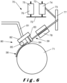
- Figure 6 schematized an automated tool 70 placing the first metal layer 21 on the first composite layer 11 (not shown) already shaped as a curved wall under construction 71.
- the automated tool 70 preferably comprises a support 72 for a spool 76 of a carbon-based ribbon 75 that will be cut in carbon-based strips 40.
- the support 72 also supports a spool 74 of metal ribbon 73 that will be cut in metal strips 30.
- the ribbons 73, 75 may be cut before being applied on the curved wall under construction 71 or after at least one part of them has been applied on the curved wall under construction 71.
- the automated tool 70 preferably comprises a guiding system 77 guiding the ribbon 73 being placed between the spool 74 and an application guide 84.
- the ribbon 73 may be heated or cooled by a heating and/or cooling device 78.
- the resin is preferably present in the carbon-based ribbon 75, and some additional resin may be added later in the production process.
- the bonding agent may be present on at least one of the ribbons 73, 75 on the spool 74, 76 or may be placed on at least one of the ribbons 73, 75 by the automated tool 70.
- the automated tool 70 may comprise a mobile part 80, for example comprising an arm 81 and a mobile head 82.
- the automated tool 70 comprises a tension application device 83 which applies a tension, preferably by pulling, on the part 39 of the metal strips 30 to be placed on the first composite layer 11, to keep it taut with respect to the part 38 of the metal strips 30 already placed on the first composite layer 11 and adhering to the curved wall under construction 71.
- the automated tool 70 may comprise a compression device 85 pressing on the part 38 of the metal strips 30 placed on the first composite layer 11.
- the curved wall 1 is preferably heated to cure the resin.
- the invention relates to a curved wall 1 comprising an alternation of metal 21and composite 11, 12 layers, and to a method to produce it.
- the metal 21layer is made of aligned metal strips 30 and can thus conform to any shape of the curved wall 1.
Landscapes
- Physics & Mathematics (AREA)
- Thermal Sciences (AREA)
- Engineering & Computer Science (AREA)
- Mechanical Engineering (AREA)
- Laminated Bodies (AREA)
Claims (15)
- Gekrümmte Wand (1), umfassend, in dieser Reihenfolge:- eine erste Verbundschicht (11),- eine erste Metallschicht (21), und- eine zweite Verbundschicht (12);wobei die erste (11) und die zweite (12) Verbundschicht Kohlenstofffasern umfassen;wobei die erste (21) Metallschicht Metallstreifen (30) aus Material auf Titanbasis umfasst;wobei die Metallstreifen (30) eine Dicke (31) zwischen 1 und 500 µm und eine Breite (32) zwischen 2 und 200 mm aufweisen;wobei die Metallstreifen (30) der ersten Metallschicht (21) mindestens 80 % der Oberfläche der ersten Metallschicht (21) bedecken.
- Gekrümmte Wand (1) nach dem vorstehenden Anspruch, wobei die gekrümmte Wand (1) mindestens einen Bereich aufweist, an dem sie nicht entwickelbar ist.
- Gekrümmte Wand (1) nach einem der vorstehenden Ansprüche, die eine zweite Metallschicht (22) derart umfasst, dass sich die zweite Verbundschicht (12) zwischen der ersten Metallschicht (21) und der zweiten Metallschicht (22) befindet, wobei die zweite Metallschicht (22) Metallstreifen (30) aus Material auf Titanbasis umfasst, die eine Dicke (31) zwischen 1 und 500 µm und eine Breite (32) zwischen 2 und 200 mm aufweisen und mindestens 80 % der Oberfläche der zweiten Metallschicht (22) bedecken.
- Gekrümmte Wand (1) nach dem vorstehenden Anspruch, wobei mindestens einige der Metallstreifen (30) der ersten Metallschicht (21) zu einer ersten Richtung (101) parallel verlaufen und mindestens einige der Metallstreifen (30) der zweiten Metallschicht (22) zu einer zweiten Richtung (102), die sich von der ersten Richtung (101) unterscheidet, parallel verlaufen.
- Gekrümmte Wand (1) nach einem der vorstehenden Ansprüche, wobei die Kohlenstofffasern der zweiten Verbundschicht (12) in Streifen auf Kohlenstoffbasis (40) beinhaltet sind.
- Gekrümmte Wand (1) nach Anspruch 5, wobei mindestens einige der Streifen auf Kohlenstoffbasis (40) der zweiten Verbundschicht (12) zu einer dritten Richtung (103) parallel verlaufen.
- Gekrümmte Wand (1) nach Anspruch 5 oder 6, wobei die Streifen auf Kohlenstoffbasis (40) eine Breite (42) aufweisen, die höchstens das Zehnfache der Breite (32) der Metallstreifen (30) der ersten Metallschicht (21) beträgt, und/oder die Breite (32) der Metallstreifen (30) der ersten Metallschicht (21) höchstens das Zehnfache der Breite (42) der Streifen auf Kohlenstoffbasis (40) beträgt.
- Gekrümmte Wand (1) nach einem der vorstehenden Ansprüche, wobei der Abstand (33) zwischen zwei aufeinanderfolgenden Metallstreifen (30) der ersten Metallschicht (21) kleiner als 5 mm, vorzugsweise kleiner als 1 mm, ist.
- Gekrümmte Wand (1) nach einem der vorstehenden Ansprüche, die an einer Grenzfläche zwischen einer der Verbundschichten (11, 12) und der ersten Metallschicht (21) ein Bindemittel umfasst, das einen Komplex aus einem Organometall und einem Organosilan umfasst.
- Kraftstofftank (50) für flüssigen und/oder gasförmigen Kraftstoff, der eine gekrümmte Wand (1) nach einem der vorstehenden Ansprüche umfasst.
- Flugzeugnase (60), die eine gekrümmte Wand (1) nach einem der Ansprüche 1 bis 9 umfasst.
- Verfahren zum Erzeugen einer gekrümmten Wand (1), das die aufeinanderfolgenden Schritte umfasst:- Bilden (111) einer ersten Verbundschicht (11),- Bilden (121) einer ersten Metallschicht (21), und- Bilden (112) einer zweiten Verbundschicht (12);wobei die erste (11) und die zweite (12) Verbundschicht Kohlenstofffasern umfassen;
wobei der Schritt des Bildens (111) der ersten Metallschichten (21) mit einem automatisierten Werkzeug (70) ausgeführt wird und das Aufbringen von Metallstreifen (30) aus Material auf Titanbasis auf die erste Verbundschicht (11) derart umfasst, dass zwischen dem Teil (38) der Metallstreifen (30), der bereits auf der ersten Verbundschicht (11) platziert ist, und dem Teil (39) der Metallstreifen (30), der auf der ersten Verbundschicht (11) platziert werden soll, eine mechanische Spannung erstellt wird, wobei die Metallstreifen (30) eine Dicke (31) zwischen 1 und 500 µm und eine Breite (32) zwischen 2 und 200 mm aufweisen;wobei die Metallstreifen (30) der ersten Metallschicht (21) mindestens 80 % der Oberfläche der ersten Metallschicht (21) bedecken, und wobei die Metallstreifen (30) einer zweiten Metallschicht (22) parallel verlaufen und mindestens 80 % der Oberfläche der zweiten Metallschicht (22) bedecken. - Verfahren nach Anspruch 12, wobei die Metallstreifen (30) der ersten Metallschicht (21), nachdem sie auf der ersten Verbundschicht (11) platziert wurden, an die erste Verbundschicht (11) gepresst werden.
- Verfahren nach Anspruch 12 oder 13, wobei das automatisierte Werkzeug (70) einen beweglichen Teil (80) umfasst, der eine Applikationsführung (84) umfasst, die den zu applizierenden Teil (39) der Metallstreifen (30) in Bezug auf die erste Verbundschicht (11) oder die zweite Verbundschicht (12) positioniert.
- Verfahren nach einem der Ansprüche 12 bis 14, wobei der zu applizierende Teil (39) der Metallstreifen (30), bevor er auf der ersten Verbundschicht (11) oder der zweiten Verbundschicht (12) platziert wird, erhitzt oder abgekühlt wird.
Priority Applications (4)
| Application Number | Priority Date | Filing Date | Title |
|---|---|---|---|
| ES22177045T ES3026534T3 (en) | 2022-06-02 | 2022-06-02 | Curved wall comprising an alternation of metal and composite layers, and method to produce it |
| EP22177045.6A EP4286151B1 (de) | 2022-06-02 | 2022-06-02 | Gekrümmte wand mit abwechselnden metall- und verbundschichten und verfahren zu ihrer herstellung |
| PCT/EP2023/064732 WO2023232965A1 (en) | 2022-06-02 | 2023-06-01 | Curved wall comprising an alternation of metal and composite layers, and method to produce it |
| US18/870,911 US20250346015A1 (en) | 2022-06-02 | 2023-06-01 | Curved wall comprising an alternation of metal and composite layers, and method to produce it |
Applications Claiming Priority (1)
| Application Number | Priority Date | Filing Date | Title |
|---|---|---|---|
| EP22177045.6A EP4286151B1 (de) | 2022-06-02 | 2022-06-02 | Gekrümmte wand mit abwechselnden metall- und verbundschichten und verfahren zu ihrer herstellung |
Publications (3)
| Publication Number | Publication Date |
|---|---|
| EP4286151A1 EP4286151A1 (de) | 2023-12-06 |
| EP4286151B1 true EP4286151B1 (de) | 2025-04-16 |
| EP4286151C0 EP4286151C0 (de) | 2025-04-16 |
Family
ID=82458761
Family Applications (1)
| Application Number | Title | Priority Date | Filing Date |
|---|---|---|---|
| EP22177045.6A Active EP4286151B1 (de) | 2022-06-02 | 2022-06-02 | Gekrümmte wand mit abwechselnden metall- und verbundschichten und verfahren zu ihrer herstellung |
Country Status (4)
| Country | Link |
|---|---|
| US (1) | US20250346015A1 (de) |
| EP (1) | EP4286151B1 (de) |
| ES (1) | ES3026534T3 (de) |
| WO (1) | WO2023232965A1 (de) |
Family Cites Families (3)
| Publication number | Priority date | Publication date | Assignee | Title |
|---|---|---|---|---|
| US5254387A (en) * | 1990-09-10 | 1993-10-19 | Daniel Gallucci | High strength multi-layered tape |
| US5866272A (en) * | 1996-01-11 | 1999-02-02 | The Boeing Company | Titanium-polymer hybrid laminates |
| US9006119B2 (en) * | 2009-10-01 | 2015-04-14 | A.L.D. Advanced Logistics Development Ltd. | Composite material, a structural element comprised of the composite material, an airplane wing spar and their methods of production |
-
2022
- 2022-06-02 EP EP22177045.6A patent/EP4286151B1/de active Active
- 2022-06-02 ES ES22177045T patent/ES3026534T3/es active Active
-
2023
- 2023-06-01 US US18/870,911 patent/US20250346015A1/en active Pending
- 2023-06-01 WO PCT/EP2023/064732 patent/WO2023232965A1/en not_active Ceased
Also Published As
| Publication number | Publication date |
|---|---|
| EP4286151A1 (de) | 2023-12-06 |
| WO2023232965A1 (en) | 2023-12-07 |
| EP4286151C0 (de) | 2025-04-16 |
| US20250346015A1 (en) | 2025-11-13 |
| ES3026534T3 (en) | 2025-06-11 |
Similar Documents
| Publication | Publication Date | Title |
|---|---|---|
| CN102026798B (zh) | 增强的硬化构件及其制造方法 | |
| US8741093B2 (en) | Tank for very low temperature liquids | |
| CN102241275B (zh) | 弯曲的复合框架及其制造方法 | |
| EP0773099A1 (de) | Verbundstruktur mit Kern aus rohrförmigen Elementen | |
| CN101939578B (zh) | 管道区段、系统及其构造方法 | |
| EP3138769B1 (de) | Radiusfüllstoffhaltige vertikallagenstapel und dünnlagen | |
| KR100760482B1 (ko) | 액화천연가스 운반선의 단열방벽 접합구조 및 그 방법 | |
| JP2009214540A (ja) | 金属−セラミックマトリックスハイブリッド複合構造の製造方法、複合構造の製造方法、および積層複合構造 | |
| KR20130096232A (ko) | 복합재-금속 조인트를 갖는 복합재 구조물과 그 제조방법 | |
| JP2015098166A (ja) | 幾何学形状充填材要素を有するラミネート複合角部充填材およびそれを形成する方法 | |
| EP3083395B1 (de) | Versteifungselement und verstärkte struktur | |
| US20230415448A1 (en) | Honeycomb core sandwich panels | |
| US20170050411A1 (en) | Panel made of laminates and method of manufacturing the same | |
| US11059239B2 (en) | Method and apparatus for composite rib and rib-and-sheet molding | |
| TW201919839A (zh) | 纖維強化塑膠及纖維強化塑膠之製造方法 | |
| EP4286151B1 (de) | Gekrümmte wand mit abwechselnden metall- und verbundschichten und verfahren zu ihrer herstellung | |
| US20240367396A1 (en) | Apparatus, system, and method for repairing composite sandwich panels | |
| EP0710728B1 (de) | Verfahren zur Herstellung einer faserverstärkten Metallscheibe | |
| EP1541910B1 (de) | Material für stopfbuchse und stopfbuchse | |
| US20160176121A1 (en) | Method of forming a laminar composite structure | |
| WO1991014565A1 (en) | Structural component | |
| EP3991955B1 (de) | Verbundkomponentensystem, verwendung eines verbundkomponentensystems und verfahren zur reparatur eines verbundkomponentensystems | |
| EP4269860B1 (de) | Verfahren zur herstellung eines behälters und eines doppelwandigen tanks | |
| JP3241417B2 (ja) | 円筒形金属系複合材料の製造方法 | |
| US20220299160A1 (en) | Fibre-reinforced pressure vessel |
Legal Events
| Date | Code | Title | Description |
|---|---|---|---|
| PUAI | Public reference made under article 153(3) epc to a published international application that has entered the european phase |
Free format text: ORIGINAL CODE: 0009012 |
|
| STAA | Information on the status of an ep patent application or granted ep patent |
Free format text: STATUS: THE APPLICATION HAS BEEN PUBLISHED |
|
| AK | Designated contracting states |
Kind code of ref document: A1 Designated state(s): AL AT BE BG CH CY CZ DE DK EE ES FI FR GB GR HR HU IE IS IT LI LT LU LV MC MK MT NL NO PL PT RO RS SE SI SK SM TR |
|
| STAA | Information on the status of an ep patent application or granted ep patent |
Free format text: STATUS: REQUEST FOR EXAMINATION WAS MADE |
|
| 17P | Request for examination filed |
Effective date: 20240605 |
|
| RBV | Designated contracting states (corrected) |
Designated state(s): AL AT BE BG CH CY CZ DE DK EE ES FI FR GB GR HR HU IE IS IT LI LT LU LV MC MK MT NL NO PL PT RO RS SE SI SK SM TR |
|
| GRAP | Despatch of communication of intention to grant a patent |
Free format text: ORIGINAL CODE: EPIDOSNIGR1 |
|
| STAA | Information on the status of an ep patent application or granted ep patent |
Free format text: STATUS: GRANT OF PATENT IS INTENDED |
|
| INTG | Intention to grant announced |
Effective date: 20241106 |
|
| GRAS | Grant fee paid |
Free format text: ORIGINAL CODE: EPIDOSNIGR3 |
|
| GRAA | (expected) grant |
Free format text: ORIGINAL CODE: 0009210 |
|
| STAA | Information on the status of an ep patent application or granted ep patent |
Free format text: STATUS: THE PATENT HAS BEEN GRANTED |
|
| AK | Designated contracting states |
Kind code of ref document: B1 Designated state(s): AL AT BE BG CH CY CZ DE DK EE ES FI FR GB GR HR HU IE IS IT LI LT LU LV MC MK MT NL NO PL PT RO RS SE SI SK SM TR |
|
| REG | Reference to a national code |
Ref country code: GB Ref legal event code: FG4D |
|
| REG | Reference to a national code |
Ref country code: CH Ref legal event code: EP |
|
| REG | Reference to a national code |
Ref country code: IE Ref legal event code: FG4D |
|
| REG | Reference to a national code |
Ref country code: DE Ref legal event code: R096 Ref document number: 602022013123 Country of ref document: DE |
|
| REG | Reference to a national code |
Ref country code: ES Ref legal event code: FG2A Ref document number: 3026534 Country of ref document: ES Kind code of ref document: T3 Effective date: 20250611 |
|
| U01 | Request for unitary effect filed |
Effective date: 20250507 |
|
| U07 | Unitary effect registered |
Designated state(s): AT BE BG DE DK EE FI FR IT LT LU LV MT NL PT RO SE SI Effective date: 20250514 |
|
| PGFP | Annual fee paid to national office [announced via postgrant information from national office to epo] |
Ref country code: NO Payment date: 20250624 Year of fee payment: 4 |
|
| U20 | Renewal fee for the european patent with unitary effect paid |
Year of fee payment: 4 Effective date: 20250728 |
|
| PGFP | Annual fee paid to national office [announced via postgrant information from national office to epo] |
Ref country code: ES Payment date: 20250731 Year of fee payment: 4 |
|
| PG25 | Lapsed in a contracting state [announced via postgrant information from national office to epo] |
Ref country code: GR Free format text: LAPSE BECAUSE OF FAILURE TO SUBMIT A TRANSLATION OF THE DESCRIPTION OR TO PAY THE FEE WITHIN THE PRESCRIBED TIME-LIMIT Effective date: 20250717 |
|
| PG25 | Lapsed in a contracting state [announced via postgrant information from national office to epo] |
Ref country code: PL Free format text: LAPSE BECAUSE OF FAILURE TO SUBMIT A TRANSLATION OF THE DESCRIPTION OR TO PAY THE FEE WITHIN THE PRESCRIBED TIME-LIMIT Effective date: 20250416 |
|
| PG25 | Lapsed in a contracting state [announced via postgrant information from national office to epo] |
Ref country code: HR Free format text: LAPSE BECAUSE OF FAILURE TO SUBMIT A TRANSLATION OF THE DESCRIPTION OR TO PAY THE FEE WITHIN THE PRESCRIBED TIME-LIMIT Effective date: 20250416 |
|
| PGFP | Annual fee paid to national office [announced via postgrant information from national office to epo] |
Ref country code: CH Payment date: 20250701 Year of fee payment: 4 |
|
| PG25 | Lapsed in a contracting state [announced via postgrant information from national office to epo] |
Ref country code: RS Free format text: LAPSE BECAUSE OF FAILURE TO SUBMIT A TRANSLATION OF THE DESCRIPTION OR TO PAY THE FEE WITHIN THE PRESCRIBED TIME-LIMIT Effective date: 20250716 |
|
| PG25 | Lapsed in a contracting state [announced via postgrant information from national office to epo] |
Ref country code: IS Free format text: LAPSE BECAUSE OF FAILURE TO SUBMIT A TRANSLATION OF THE DESCRIPTION OR TO PAY THE FEE WITHIN THE PRESCRIBED TIME-LIMIT Effective date: 20250816 |