EP4286068A1 - Method and device for operating a work roll during hot rolling - Google Patents
Method and device for operating a work roll during hot rolling Download PDFInfo
- Publication number
- EP4286068A1 EP4286068A1 EP22177058.9A EP22177058A EP4286068A1 EP 4286068 A1 EP4286068 A1 EP 4286068A1 EP 22177058 A EP22177058 A EP 22177058A EP 4286068 A1 EP4286068 A1 EP 4286068A1
- Authority
- EP
- European Patent Office
- Prior art keywords
- roll
- work roll
- work
- strip
- rolled
- Prior art date
- Legal status (The legal status is an assumption and is not a legal conclusion. Google has not performed a legal analysis and makes no representation as to the accuracy of the status listed.)
- Pending
Links
- 238000000034 method Methods 0.000 title claims abstract description 24
- 238000005098 hot rolling Methods 0.000 title claims abstract description 21
- 238000005096 rolling process Methods 0.000 claims abstract description 93
- 239000012459 cleaning agent Substances 0.000 claims abstract description 43
- 239000000314 lubricant Substances 0.000 claims abstract description 36
- 238000001816 cooling Methods 0.000 claims description 36
- XLYOFNOQVPJJNP-UHFFFAOYSA-N water Substances O XLYOFNOQVPJJNP-UHFFFAOYSA-N 0.000 claims description 35
- 238000004140 cleaning Methods 0.000 claims description 34
- 239000000498 cooling water Substances 0.000 claims description 28
- 230000001050 lubricating effect Effects 0.000 claims description 19
- 239000003599 detergent Substances 0.000 claims description 16
- 239000000203 mixture Substances 0.000 claims description 4
- 239000002826 coolant Substances 0.000 description 11
- 238000005461 lubrication Methods 0.000 description 6
- 238000007796 conventional method Methods 0.000 description 4
- 230000007423 decrease Effects 0.000 description 3
- 239000007921 spray Substances 0.000 description 3
- 238000000418 atomic force spectrum Methods 0.000 description 2
- 238000010586 diagram Methods 0.000 description 2
- 238000009826 distribution Methods 0.000 description 2
- 238000009420 retrofitting Methods 0.000 description 2
- 238000002485 combustion reaction Methods 0.000 description 1
- 239000004519 grease Substances 0.000 description 1
- 239000007769 metal material Substances 0.000 description 1
- 238000001953 recrystallisation Methods 0.000 description 1
- 238000005507 spraying Methods 0.000 description 1
Images

Classifications
-
- B—PERFORMING OPERATIONS; TRANSPORTING
- B21—MECHANICAL METAL-WORKING WITHOUT ESSENTIALLY REMOVING MATERIAL; PUNCHING METAL
- B21B—ROLLING OF METAL
- B21B27/00—Rolls, roll alloys or roll fabrication; Lubricating, cooling or heating rolls while in use
- B21B27/06—Lubricating, cooling or heating rolls
- B21B27/10—Lubricating, cooling or heating rolls externally
- B21B2027/103—Lubricating, cooling or heating rolls externally cooling externally
-
- B—PERFORMING OPERATIONS; TRANSPORTING
- B21—MECHANICAL METAL-WORKING WITHOUT ESSENTIALLY REMOVING MATERIAL; PUNCHING METAL
- B21B—ROLLING OF METAL
- B21B2273/00—Path parameters
- B21B2273/12—End of product
- B21B2273/14—Front end or leading end
-
- B—PERFORMING OPERATIONS; TRANSPORTING
- B21—MECHANICAL METAL-WORKING WITHOUT ESSENTIALLY REMOVING MATERIAL; PUNCHING METAL
- B21B—ROLLING OF METAL
- B21B2273/00—Path parameters
- B21B2273/12—End of product
- B21B2273/16—Tail or rear end
Definitions
- the invention relates to a method and a device for operating a work roll when hot rolling several rolled strips.
- the rolled strip is passed through a rolling train (hot rolling train) at a temperature above the recrystallization temperature of the metallic material to be processed, in which the rolled strip is reduced from an inlet thickness, for example between 10 mm and 50 mm, to a desired final thickness, for example, up to a minimum of 1.2 mm, is hot rolled.
- the rolling train usually includes several rolling stands in which the rolled strip is guided through a roll gap between two rotating work rolls.
- a lubricant is applied to the work rolls. Applying lubricant to the work rolls has two main advantages.
- the lubricant reduces the friction between the rolled strip and the work rolls in the roll gap and thereby the rolling forces and torques required for rolling and thus leads to energy savings in the rolling process.
- the reduced friction between the rolled strip and the work rolls in the roll gap leads to an increase in the surface quality of the rolled strip compared to a hot rolling process without lubricant.
- the section of a rolled strip that is first passed through the nip of a roll stand is called the strip head.
- the strip head has a length that is twice the circumference of each work roll, so that the strip head is guided through the roll gap during two revolutions of the work rolls.
- the section of a rolled strip that last passes through the nip of a roll stand is called the strip foot.
- the band foot has a length that is three to five times as large as the circumference of each work roll, so that the band foot is guided through the roll gap during three to five revolutions of the work rolls.
- the invention relates to the hot rolling of several rolled strips, which are passed one after the other through a rolling train, so that a rolling break is created on each rolling stand between two successive rolling strips, during which there is no rolled strip in the rolling gap between the work rolls of the rolling stand.
- a rolling break the work rolls of a rolling stand do not stop, but continue to rotate, as the rolling stand is adjusted to the following rolling strip.
- the subsequent rolled strip requires a changed target thickness on the roll stand in question, so that the roll gap must be changed accordingly and the work rolls are accelerated or braked to a changed rotational speed according to a pass schedule distribution must.
- the pass plan distribution refers to the entirety of all pass decreases in the rolling stands of the rolling mill, with a pass decrease in a roll stand being expressed, for example, by a percentage reduction in the thickness of the rolled strip in the relevant roll stand in order to achieve a desired final thickness at the exit of the rolling mill.
- the setting value for the roll gap which is automatically set by a control system of the rolling train, follows from the pass removal of an individual rolling stand, taking into account the springing of the stand.
- the invention is based on the object of reducing the rolling forces required for rolling the strip feet of the rolled strips during the successive hot rolling of several rolled strips and of improving the surface quality of the strip feet.
- the object is achieved according to the invention by a method with the features of claim 1 and a device with the features of claim 10.
- the rolled strips are guided one after the other through a roll gap between the work roll and another work roll, so that the roll gap is left by a strip end of a rolled strip and the roll gap is reached through a strip start of the subsequent rolled strip are separated from each other in time by a rolling break.
- a lubricant is applied to a roll surface of the work roll from a point in time at which a strip head of the rolled strip has completely passed through the roll gap until the strip end of the rolled strip leaves the roll gap.
- the work roll is cleaned of the lubricant by applying a cleaning agent to the roll surface of the work roll.
- rolling breaks of a work roll in which the work roll is not used for rolling between the rolling of two rolled strips, are used to clean the work roll of lubricant that was previously applied to the work roll when rolling a rolled strip.
- a rolling break is, for example, a time period in the range of 10 s to 30 s.
- a cleaning agent is dispensed onto the roll surface of the work roll during the rolling breaks. Cleaning the work roll during the rolling break makes it possible to thread a rolled strip after the rolling break with sufficient friction between the roll surface and the rolled strip.
- the lubrication of the roll surface to be maintained during the rolling of the strip feet of the rolled strips rolled by the work roll. Compared to rolling the band feet without adding lubricant, the rolling force and energy required for rolling the band feet are reduced and the surface quality of the band feet is improved.
- the cleaning agent used is water or water with a detergent dissolved in the water, in particular hot water or hot water with a detergent dissolved in the water, applied under pressure by a cleaning device to the roll surface of the work roll, for example by spraying.
- the cleaning agent is applied to the roller surface, for example by a cleaning roller as a cleaning device.
- the cleaning agent is applied by the cleaning device to the roll surface of the work roll on an inlet side of the work roll, from which the rolled strips are fed to the roll gap.
- cooling water is applied to the roll surface of the work roll by a cooling device on an outlet side of the work roll, to which the rolled strips leave the roll gap.
- a cleaning device is used to dispense water or water with a detergent dissolved in the water onto the roll surface as a cleaning agent for cleaning the roll surface of the work roll.
- a cleaning agent for cleaning the roll surface of the work roll.
- the cleaning agent is applied to the roll surface on the inlet side and the cooling water is applied to the roll surface on the outlet side.
- the cleaning agent used is water with a detergent dissolved in the water from a cooling device which is used to dispense cooling water onto the roll surface of the work roll is set up, applied under pressure to the roll surface of the work roll.
- the cleaning agent is applied to the roll surface of the work roll by the cooling device on an outlet side of the work roll, to which the rolled strips leave the roll gap.
- a cooling device is used to dispense the cleaning agent onto the roll surface of the work roll during the rolling breaks, which is set up to dispense cooling water onto the roll surface of the work roll.
- This embodiment of the invention is particularly suitable for retrofitting existing rolling stands that already have such cooling devices.
- the cooling devices are used during the rolling of rolled strips as usual to dispense cooling water to the work rolls and during the rolling breaks to dispense the cleaning agent, which is water with a detergent dissolved in it. Retrofitting such a rolling stand therefore only requires adding detergent to the water dispensed by the cooling devices during the rolling breaks and a control system that controls this addition.
- a mixture of oil and water is dispensed onto the roll surface of the work roll as a lubricant.
- the mixture has an oil content in the range of 1% to 5%.
- the cleaning agent is dispensed onto the roll surface of the work roll at a pressure in the range of 2 bar to 50 bar.
- the strip head of a rolled strip has a length that is approximately twice as large as the circumference of the work roll. A strip head of this length is usually sufficient to thread a rolled strip into a rolling stand.
- a device for operating a work roll during hot rolling of several rolled strips, which are guided one after the other through a roll gap between the work roll and another work roll, so that leaving the roll gap through a strip end of a rolled strip and reaching the roll gap through a strip start of the subsequent rolled strip are timed are separated from each other by a rolling break, includes a lubricating device, a cleaning device and a control unit.
- the lubricating device is set up to apply a lubricant to a roll surface of the work roll.
- the cleaning device is set up to dispense a cleaning agent onto the roll surface of the work roll.
- the control unit is set up to control the lubricating device and the cleaning device in such a way that during the passage of each rolled strip through the roll gap from a point in time at which a strip head of the rolled strip has completely passed through the roll gap until it leaves the roll gap
- lubricant is dispensed from the lubricating device onto the roll surface of the work roll and during each rolling break, cleaning agent is applied to the roll surface of the work roll by the cleaning device.
- the cleaning device is arranged on an inlet side of the work roll, from which the rolled strips are fed to the roll gap.
- a cooling device On an outlet side of the work roll, to which the rolled strips leave the roll gap, a cooling device is arranged, for example, which is set up to dispense cooling water onto the roll surface of the work roll, wherein the control unit is set up to control the cooling device in such a way that during the dispensing of the cleaning agent Cooling water is dispensed from the cooling device onto the roll surface of the work roll by the cleaning device.
- Such a device enables the method according to the invention to be carried out. Therefore, the advantages of such a device correspond to the above-mentioned advantages of the method according to the invention.
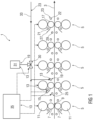
- FIG 1 shows schematically a rolling train 1 for hot rolling rolled strips 3.
- the rolling train 1 has five rolling stands 5 as an example.
- Each roll stand 5 has two work rolls 7, which are spaced apart from one another by a roll gap 9.
- each roll stand 5 has a support roll 11 for each work roll 7, which is arranged on a side of the work roll 7 facing away from the roll gap 9 and can be adjusted to the work roll 7.
- the rolling train 1 has for each work roll 7 an exemplary embodiment of a device 13 according to the invention for operating the work roll 7 during hot rolling of several Rolled strips 3 on.
- Each of these devices 13 includes a lubricating device 15, which is set up to dispense a lubricant 16 onto a roll surface 17 of the work roll 7, and a cleaning device 19, which is set up to dispense a cleaning agent 20 onto the roll surface 17 of the work roll 7.
- Each lubricating device 15 comprises at least one lubricating bar 21 with a plurality of lubricating nozzles for dispensing the lubricant 16.
- the lubricant 16 is a mixture of oil and water, for example with an oil content in the range of 1% to 5%.
- the cleaning device 19 of a device 13 comprises at least one cooling bar 22 of a cooling device 23, which is set up to dispense cooling water 24 onto the roll surface 17 of the respective work roll 7.
- Each cooling beam 22 has a plurality of cooling nozzles for dispensing the cooling water 24.
- the rolling train 1 includes an anti-peeling device 25 and a scraper 27 for each work roll 7.
- the anti-peeling device 25 is set up to apply an anti-peeling coolant 26 to the rolled strips 3 and includes at least one for this purpose Anti-peel spray bar 29 with several anti-peel nozzles.
- the anti-peeling coolant 26 cools a surface of a hot rolled strip 3 shortly before entering the roll gap 9 and thereby prevents thermal surface damage to the respective work roll 7, such as peeling off an oxide layer of the work roll 7.
- An anti-peeling coolant 26 is used, for example Cooling water used.
- Each scraper 27 for a work roll 7 can be adjusted to the roll surface 17 of the work roll 7 in order to keep cooling water 24 dispensed onto the work roll 7 away from the rolled strips 3.
- the lubricating device 15, the anti-peeling device 25 and the scraper 27, which are assigned to a work roll 7, are arranged on an inlet side of the work roll 7, from which the rolled strips 3 are fed to the roll gap 9.
- the cooling device 23 assigned to a work roll 7 is arranged on an outlet side of the work roll 7, to which the rolled strips 3 leave the roll gap 9.
- the lubricant 16 and the anti-peeling coolant 26 are therefore applied to the roll surface 17 of the work roll 7 on the inlet side of the work roll 7, and the cooling water 24 and the cleaning agent 20 are applied to the roll surface 17 of the work roll 7 on the outlet side.
- the anti-peel coolant 26 is dispensed onto the rolled strip 3, for example, in an amount of approximately 100 m 3 /h per roll stand 5 and at a pressure of approximately 3 bar.
- the cooling water 24 is applied from the cooling devices 23 to the work rolls 7, for example in an amount of approximately 1000 m 3 /h per roll stand 5 and at a pressure of approximately 5 bar to 15 bar.
- the output of lubricant 16 by the lubricating devices 15 of the roll stand 5 and the output of anti-peeling coolant 26 are adjusted by the anti-peel devices 25 of the roll stand 5 and from the cooling devices 23 of the roll stand 5, instead of the cooling water 24, the cleaning agent 20 is dispensed onto the roll surfaces 17 of the work rolls 7 of the roll stand 5.
- the temperature of the cleaning agent 20 is, for example, in a range from 20 ° C to 60 ° C.
- the cleaning agent 20 is dispensed by the cooling devices 23, for example at a pressure of approximately 5 bar.
- the concentration of the detergent in the water is, for example, between 0% and 10%, preferably between 0.5% and 5%.
- the dosage of the cleaning agent 20 for the rolling stands 5 is adjusted with at least one metering valve 30, to which the detergent from a detergent reservoir 31 and water from a cooling water supply 33 can be supplied.
- the lubricating devices 15, cooling devices 23, anti-peeling devices 25 and the at least one metering valve 30 are controlled by a control unit 35.
- This is in Figure 1 indicated by dashed arrows as an example for the upper work roll 7 of the second roll stand 5 of the rolling train 1.
- the control unit 35 also controls the further stand settings of the roll stands 5 of the work rolls 7, in particular the distances between the two work rolls 7 of each roll stand 5 and thus the sizes of the roll gaps 9 of the roll stands 5 as well as the angular speeds at which the work rolls 7 and the support rolls 11 rotate.
- This is in Figure 1 indicated by dashed arrows pointing to the support rollers 11.
- the control unit 35 is therefore a control system for the rolling mill 1.
- FIG 2 shows schematically a roll stand 5 with a second exemplary embodiment of devices 13 for operating the work rolls 7 during hot rolling of several rolled strips in a rolling train 1.
- This exemplary embodiment differs from that in Figure 1 shown embodiment essentially in that the cleaning device 19 of each device 13 has at least one separate cleaning bar 37 with several cleaning nozzles with which the cleaning agent 20 can be dispensed onto the roll surface 17 of a work roll 7.
- the cleaning nozzles are, for example, flat jet nozzles, each of which emits a jet with an opening angle of, for example, approximately 90 degrees.
- the cleaning bars 37 are arranged on the inlet side of the roll stand 5, so that the cleaning agent 20 is dispensed onto the roll surfaces 17 of the work rolls 7 on the inlet side.
- a lubricating device 15 with at least one lubricating bar 21 is also arranged for each work roll 7, with which a lubricant 16 can be dispensed onto the roll surface 17 of the work roll 7.
- two anti-peel devices 25, each with at least one anti-peel spray bar 29, are arranged on the inlet side of the roll stand 5, with which an anti-peel coolant 26 can be dispensed onto the top surface and the bottom surface of a rolled strip 7 .
- a cooling device 23 with several cooling beams 22 is arranged for each work roll 7, with which cooling water 24 can be dispensed onto the roll surface 17 of the work roll 7.
- cooling device 23 can also have cooling beams 22 arranged on the inlet side (in Figure 2 not shown). In such a case, for example, 20% to 30% of the cooling water 24 is applied to the roll surface 17 on the inlet side of the roll stand 5.
- each rolled strip 3 through a roll gap 9 of a roll stand 5, from a time t 2 at which a strip head of the rolled strip 3 has completely passed through the roll gap 9, until the strip end of the rolled strip 7 leaves the roll gap 9 from the lubricating devices 15 of the roll stand 5, the lubricant 16 is applied to the roll surfaces 17 of the work rolls 7 of the roll stand 5.
- the anti-peeling coolant 26 is dispensed onto the rolled strip 3 from the anti-peeling devices 25 of the roll stand 5 and cooling water 24 is applied to the roll surfaces 17 of the work rolls 7 of the roll stand 5 from the cooling devices 23 of the roll stand 5.
- the cleaning devices 19 are switched off, so that no cleaning agent 20 is applied to the roll surfaces 17 of the work rolls 7.
- the output of lubricant 16 by the lubricating devices 15 of the roll stand 5 and the output of anti-peel coolant 26 by the anti-peel devices 25 of the roll stand 5 are adjusted. Furthermore, during each rolling break ⁇ t, the cleaning agent 20 is dispensed from the cleaning devices 19 onto the roll surfaces 17 of the work rolls 7, and cooling water 24 is dispensed from the cooling devices 23 of the roll stand 5 onto the roll surfaces 17 of the work rolls 7 of the roll stand 5.
- the cleaning agent 20 used by the cleaning devices 19 is, for example, water or water with a detergent dissolved in the water, in particular hot water (for example water with a temperature greater than 35 ° C) or hot water with a detergent dissolved in the water, pressurized onto the roller surfaces 17 of the work rolls 7 are issued.
- the cleaning agent 20 is dispensed from the cleaning devices 19 at a pressure in the range of 2 bar to 50 bar.
- the lubricant 16 remaining on the work rolls 7 is dissolved by the cleaning agent 20 and washed off the roll surfaces 17 of the work rolls 7 by the cooling water 24 discharged from the cooling devices 23.
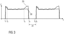
- FIG 3 illustrates the method according to the invention for operating a work roll 7 when hot rolling several rolled strips by a diagram of a rolling force F acting on rolled strips 3 in a rolling stand 5 as a function of time t in comparison to a conventional method.
- 38 denotes a force curve of the rolling force F in the method according to the invention and 39 denotes a force curve of the rolling force F in the conventional method.
- t 1 the beginning of a rolled strip 3 reaches the rolling gap 9 of the rolling stand 5, as a result of which the rolling force F increases steeply.
- a band head of the rolled strip 3 has completely passed through the roll gap 9.
- the band head for example, has a length that is twice as large as the circumference of the work roll 7, so that the band head is guided through the roll gap 9 during two revolutions of the work roll 7. From time t 2 , the lubricant 16 is dispensed onto the roll surface 17 of the work roll 7 both in the method according to the invention and in the conventional method. As a result, the rolling force F decreases in both processes compared to rolling the roll head.
- the lubrication of the roll surface 17 of the work roll 7 is set at a time t 3 at which a band foot of the rolled strip 3 reaches the roll gap 9.
- the band foot for example, has a length that is three to five times as large as the circumference of the work roll 7, so that the band foot is guided through the roll gap 9 during three to five revolutions of the work roll 7.
- lubricant 16 remaining on the roll surface 17 of the work roll 7 burns in the roll gap 9 due to the high temperature of the rolled strip 3. Since during this As long as no lubricant 16 is supplied to the roll surface 17 of the work roll 7, the friction increases between Roll surface 17 and the rolled strip 3 and thus the rolling force F from time t 3 to time t 4 again.
- the lubrication of the roll surface 17 of the work roll 7 is maintained from time t2 to time t4, so that the roll surface 17 is lubricated throughout the entire passage of the strip foot through the roll gap 9.
- a rolling break ⁇ t from the time t 4 to a time t 6 at which the beginning of the strip of the subsequent rolled strip 3 reaches the roll gap 9, there is no rolled strip 3 in the roll gap 9, so that the rolling force F disappears during the rolling break ⁇ t.
- the roll surface 17 of the work roll 7 is cleaned from the time t 4 to a time t 5 during the rolling break ⁇ t by dispensing the cleaning agent 20 onto the roll surface 17, so that at the time t 6 there is no or only very little there is little lubricant 16 on the roller surface 17.
- the lubrication of the roll surface 17 is only resumed when the strip head of the subsequent rolled strip 3 has completely passed the roll gap 9.
Abstract
Die Erfindung betrifft ein Verfahren und eine Vorrichtung (13) zum Betreiben einer Arbeitswalze (7) beim Warmwalzen mehrerer Walzbänder (3). Bei dem Verfahren werden die Walzbänder (3) nacheinander durch einen Walzspalt (9) zwischen der Arbeitswalze (7) und einer weiteren Arbeitswalze (7) geführt, so dass das Verlassen des Walzspaltes (9) durch ein Bandende eines Walzbandes (3) und das Erreichen des Walzspaltes (9) durch einen Bandanfang des nachfolgenden Walzbandes (3) zeitlich durch eine Walzpause Δt voneinander getrennt sind. Während des Durchgangs jedes Walzbandes (3) durch den Walzspalt (9) wird von einem Zeitpunkt t<sub>2</sub>, zu dem ein Bandkopf des Walzbandes (3) den Walzspalt (9) vollständig passiert hat, bis zum Verlassen des Walzspaltes (9) durch das Bandende des Walzbandes (3) ein Schmiermittel (16) auf eine Walzenoberfläche (17) der Arbeitswalze (7) aufgebracht. Während jeder Walzpause Δt wird die Arbeitswalze (7) durch Aufbringen eines Reinigungsmittels (20) auf die Walzenoberfläche (17) der Arbeitswalze (7) von dem Schmiermittel (16) gereinigt.The invention relates to a method and a device (13) for operating a work roll (7) during hot rolling of several rolled strips (3). In the method, the rolled strips (3) are guided one after the other through a roll gap (9) between the work roll (7) and another work roll (7), so that the roll gap (9) leaves the roll gap (9) through a strip end of a rolled strip (3) and that Reaching the roll gap (9) through a strip start of the subsequent rolled strip (3) are separated from each other in time by a rolling break Δt. During the passage of each rolled strip (3) through the roll gap (9), from a time t<sub>2</sub>, at which a strip head of the rolled strip (3) has completely passed the roll gap (9), until it leaves the Roll gap (9) through the band end of the rolled strip (3) a lubricant (16) is applied to a roll surface (17) of the work roll (7). During each rolling break Δt, the work roll (7) is cleaned of the lubricant (16) by applying a cleaning agent (20) to the roll surface (17) of the work roll (7).
Description
Die Erfindung betrifft ein Verfahren und eine Vorrichtung zum Betreiben einer Arbeitswalze beim Warmwalzen mehrerer Walzbänder.The invention relates to a method and a device for operating a work roll when hot rolling several rolled strips.
Beim Warmwalzen eines metallischen Walzbandes wird das Walzband bei einer Temperatur oberhalb der Rekristallisationstemperatur des zu verarbeitenden metallischen Werkstoffes durch eine Walzstraße (Warmwalzstraße) geführt, in der das Walzband von einer Einlaufdicke, die beispielsweise zwischen 10 mm und 50 mm liegt, auf eine gewünschte Enddicke, beispielsweise bis zu minimal 1,2 mm, warmgewalzt wird. Die Walzstraße umfasst in der Regel mehrere Walzgerüste, in denen das Walzband jeweils durch einen Walzspalt zwischen zwei rotierenden Arbeitswalzen geführt wird. Dabei wird in der Regel ein Schmiermittel auf die Arbeitswalzen aufgegeben. Die Aufgabe von Schmiermittel auf die Arbeitswalzen hat zwei wesentliche Vorteile. Zum einen reduziert das Schmiermittel die Reibung zwischen dem Walzband und den Arbeitswalzen in dem Walzspalt und dadurch die zum Walzen benötigten Walzkräfte und Drehmomente und führt damit zu einer Energieeinsparung beim Walzprozess. Zum andern führt die reduzierte Reibung zwischen dem Walzband und den Arbeitswalzen in dem Walzspalt zu einer Erhöhung der Oberflächenqualität des Walzbandes gegenüber einem Warmwalzprozess ohne Schmiermittel.When hot rolling a metallic rolled strip, the rolled strip is passed through a rolling train (hot rolling train) at a temperature above the recrystallization temperature of the metallic material to be processed, in which the rolled strip is reduced from an inlet thickness, for example between 10 mm and 50 mm, to a desired final thickness, for example, up to a minimum of 1.2 mm, is hot rolled. The rolling train usually includes several rolling stands in which the rolled strip is guided through a roll gap between two rotating work rolls. As a rule, a lubricant is applied to the work rolls. Applying lubricant to the work rolls has two main advantages. On the one hand, the lubricant reduces the friction between the rolled strip and the work rolls in the roll gap and thereby the rolling forces and torques required for rolling and thus leads to energy savings in the rolling process. On the other hand, the reduced friction between the rolled strip and the work rolls in the roll gap leads to an increase in the surface quality of the rolled strip compared to a hot rolling process without lubricant.
Der Abschnitt eines Walzbandes, der zuerst durch den Walzspalt eines Walzgerüstes geführt wird, wird als Bandkopf bezeichnet. Der Bandkopf hat beispielsweise eine Länge, die zweimal so groß wie der Umfang jeder Arbeitswalze ist, so dass der Bandkopf während zwei Umdrehungen der Arbeitswalzen durch den Walzspalt geführt wird. Der Abschnitt eines Walzbandes, der zuletzt den Walzspalt eines Walzgerüstes passiert, wird als Bandfuß bezeichnet. Der Bandfuß hat beispielsweise eine Länge, die dreimal bis fünfmal so groß wie der Umfang jeder Arbeitswalze ist, so dass der Bandfuß während drei bis fünf Umdrehungen der Arbeitswalzen durch den Walzspalt geführt wird.The section of a rolled strip that is first passed through the nip of a roll stand is called the strip head. For example, the strip head has a length that is twice the circumference of each work roll, so that the strip head is guided through the roll gap during two revolutions of the work rolls. The section of a rolled strip that last passes through the nip of a roll stand is called the strip foot. For example, the band foot has a length that is three to five times as large as the circumference of each work roll, so that the band foot is guided through the roll gap during three to five revolutions of the work rolls.
Die Erfindung betrifft das Warmwalzen mehrerer Walzbänder, die nacheinander durch eine Walzstraße geführt werden, so dass an jedem Walzgerüst zwischen zwei aufeinander folgenden Walzbändern eine Walzpause entsteht, während der sich in dem Walzspalt zwischen den Arbeitswalzen des Walzgerüstes kein Walzband befindet. Während einer Walzpause bleiben die Arbeitswalzen eines Walzgerüstes nicht stehen, sondern drehen weiter, da das Walzgerüst auf das nachfolgende Walzband eingestellt wird. Beispielsweise erfordert das nachfolgende Walzband eine geänderte Solldicke am betreffenden Walzgerüst, so dass der Walzspalt entsprechend geändert werden muss und die Arbeitswalzen entsprechend einer Stichplanverteilung auf eine geänderte Umdrehungsgeschwindigkeit beschleunigt oder abgebremst werden müssen. Die Stichplanverteilung bezeichnet dabei die Gesamtheit aller Stichabnahmen in den Walzgerüsten der Walzstraße, wobei eine Stichabnahme in einem Walzgerüst beispielsweise durch eine prozentuale Dickenreduktion des Walzbandes in dem betreffenden Walzgerüst für die Erreichung einer gewünschten Enddicke am Ausgang der Walzstraße ausgedrückt wird. Aus der Stichabnahme eines einzelnen Walzgerüstes folgt unter Berücksichtigung der Auffederung des Gerüstes unmittelbar dessen Einstellungswert für den Walzspalt, der automatisch von einer Steuerung der Walzstraße eingestellt wird.The invention relates to the hot rolling of several rolled strips, which are passed one after the other through a rolling train, so that a rolling break is created on each rolling stand between two successive rolling strips, during which there is no rolled strip in the rolling gap between the work rolls of the rolling stand. During a rolling break, the work rolls of a rolling stand do not stop, but continue to rotate, as the rolling stand is adjusted to the following rolling strip. For example, the subsequent rolled strip requires a changed target thickness on the roll stand in question, so that the roll gap must be changed accordingly and the work rolls are accelerated or braked to a changed rotational speed according to a pass schedule distribution must. The pass plan distribution refers to the entirety of all pass decreases in the rolling stands of the rolling mill, with a pass decrease in a roll stand being expressed, for example, by a percentage reduction in the thickness of the rolled strip in the relevant roll stand in order to achieve a desired final thickness at the exit of the rolling mill. The setting value for the roll gap, which is automatically set by a control system of the rolling train, follows from the pass removal of an individual rolling stand, taking into account the springing of the stand.
Beim Einfädeln eines Walzbandes in ein Walzgerüst, das heißt während der Bandkopf durch den Walzspalt geführt wird, müssen die Arbeitswalzen des Walzgerüstes frei von Schmiermittel sein, da das Einfädeln eine erhöhte Reibung zwischen dem Walzband und den Arbeitswalzen in dem Walzspalt erfordert. Dies wird beispielsweise dadurch erreicht, dass während des Walzens des Bandfußes eines Walzbandes in einem Walzgerüst die Schmierung der Arbeitswalzen des Walzgerüstes abgeschaltet wird und erst nach dem Walzen des Bandkopfes des nachfolgenden Walzbandes wieder zugeschaltet wird, so dass das auf den Arbeitswalzen verbliebene Schmiermittel während des Walzens des Bandfußes aufgrund der hohen Walzbandtemperatur durch Verbrennung im Walzspalt verschwindet. Daraus resultiert jedoch eine erhöhte benötigte Walzkraft während des Walzens des Bandfußes sowie eine reduzierte Oberflächenqualität des Bandfußes.When threading a rolled strip into a roll stand, that is, while the strip head is guided through the roll gap, the work rolls of the roll stand must be free of lubricant, since threading requires increased friction between the rolled strip and the work rolls in the roll gap. This is achieved, for example, by switching off the lubrication of the work rolls of the roll stand during the rolling of the band foot of a rolled strip in a rolling stand and only switching it on again after the rolling of the strip head of the subsequent rolled strip, so that the lubricant remaining on the work rolls is switched on during rolling of the strip foot disappears due to combustion in the roll gap due to the high rolled strip temperature. However, this results in an increased rolling force required during rolling of the strip foot and a reduced surface quality of the strip foot.
Der Erfindung liegt die Aufgabe zugrunde, beim aufeinander folgenden Warmwalzen mehrerer Walzbänder die für das Walzen der Bandfüße der Walzbänder benötigten Walzkräfte zu reduzieren und die Oberflächenqualität der Bandfüße zu verbessern.The invention is based on the object of reducing the rolling forces required for rolling the strip feet of the rolled strips during the successive hot rolling of several rolled strips and of improving the surface quality of the strip feet.
Die Aufgabe wird erfindungsgemäß durch ein Verfahren mit den Merkmalen des Anspruchs 1 und eine Vorrichtung mit den Merkmalen des Anspruchs 10 gelöst.The object is achieved according to the invention by a method with the features of claim 1 and a device with the features of claim 10.
Vorteilhafte Ausgestaltungen der Erfindung sind Gegenstand der Unteransprüche.Advantageous embodiments of the invention are the subject of the subclaims.
Bei dem erfindungsgemäßen Verfahren zum Betreiben einer Arbeitswalze beim Warmwalzen mehrerer Walzbänder werden die Walzbänder nacheinander durch einen Walzspalt zwischen der Arbeitswalze und einer weiteren Arbeitswalze geführt, so dass das Verlassen des Walzspaltes durch ein Bandende eines Walzbandes und das Erreichen des Walzspaltes durch einen Bandanfang des nachfolgenden Walzbandes zeitlich durch eine Walzpause voneinander getrennt sind. Während des Durchgangs jedes Walzbandes durch den Walzspalt wird von einem Zeitpunkt, zu dem ein Bandkopf des Walzbandes den Walzspalt vollständig passiert hat, bis zum Verlassen des Walzspaltes durch das Bandende des Walzbandes ein Schmiermittel auf eine Walzenoberfläche der Arbeitswalze aufgegeben. Während jeder Walzpause wird die Arbeitswalze durch Aufbringung eines Reinigungsmittels auf die Walzenoberfläche der Arbeitswalze von dem Schmiermittel gereinigt.In the method according to the invention for operating a work roll when hot rolling several rolled strips, the rolled strips are guided one after the other through a roll gap between the work roll and another work roll, so that the roll gap is left by a strip end of a rolled strip and the roll gap is reached through a strip start of the subsequent rolled strip are separated from each other in time by a rolling break. During the passage of each rolled strip through the roll gap, a lubricant is applied to a roll surface of the work roll from a point in time at which a strip head of the rolled strip has completely passed through the roll gap until the strip end of the rolled strip leaves the roll gap. During each rolling break, the work roll is cleaned of the lubricant by applying a cleaning agent to the roll surface of the work roll.
Bei dem erfindungsgemäßen Verfahren werden also Walzpausen einer Arbeitswalze, in denen die Arbeitswalze zwischen dem Walzen zweier Walzbänder nicht zum Walzen verwendet wird, genutzt, um die Arbeitswalze von Schmiermittel zu reinigen, das vorher beim Walzen eines Walzbandes auf die Arbeitswalze aufgetragen wurde. Eine Walzpause ist beispielsweise eine Zeitdauer im Bereich von 10 s bis 30 s. Zur Reinigung der Arbeitswalze wird dabei während der Walzpausen ein Reinigungsmittel auf die Walzenoberfläche der Arbeitswalze ausgegeben. Durch die Reinigung der Arbeitswalze während der Walzpause wird zum einen das Einfädeln eines Walzbandes nach der Walzpause mit ausreichender Reibung zwischen der Walzenoberfläche und dem Walzband ermöglicht. Zum andern wird ermöglicht, dass die Schmierung der Walzenoberfläche während des Walzens der Bandfüße der von der Arbeitswalze gewalzten Walzbänder aufrechterhalten werden kann. Gegenüber einem Walzen der Bandfüße ohne Zugabe von Schmiermittel werden dadurch die zum Walzen der Bandfüße benötigte Walzkraft und die dafür benötigte Energie reduziert und die Oberflächenqualität der Bandfüße wird verbessert.In the method according to the invention, rolling breaks of a work roll, in which the work roll is not used for rolling between the rolling of two rolled strips, are used to clean the work roll of lubricant that was previously applied to the work roll when rolling a rolled strip. A rolling break is, for example, a time period in the range of 10 s to 30 s. To clean the work roll, a cleaning agent is dispensed onto the roll surface of the work roll during the rolling breaks. Cleaning the work roll during the rolling break makes it possible to thread a rolled strip after the rolling break with sufficient friction between the roll surface and the rolled strip. On the other hand, it is made possible for the lubrication of the roll surface to be maintained during the rolling of the strip feet of the rolled strips rolled by the work roll. Compared to rolling the band feet without adding lubricant, the rolling force and energy required for rolling the band feet are reduced and the surface quality of the band feet is improved.
Bei einer Ausgestaltung der Erfindung wird als Reinigungsmittel Wasser oder Wasser mit einem in dem Wasser gelösten Detergens, insbesondere heißes Wasser oder heißes Wasser mit einem in dem Wasser gelösten Detergens, von einer Reinigungsvorrichtung druckbeaufschlagt auf die Walzenoberfläche der Arbeitswalze aufgebracht, beispielsweise durch Aufsprühen. Alternativ wird das Reinigungsmittel beispielsweise durch eine Reinigungswalze als Reinigungsvorrichtung auf die Walzenoberfläche aufgebracht. Beispielsweise wird das Reinigungsmittel dabei auf einer Einlaufseite der Arbeitswalze, von der aus die Walzbänder dem Walzspalt zugeführt werden, von der Reinigungsvorrichtung auf die Walzenoberfläche der Arbeitswalze aufgetragen. Ferner wird beispielsweise während der Ausgabe des Reinigungsmittels von einer Kühlvorrichtung auf einer Auslaufseite der Arbeitswalze, zu der die Walzbänder den Walzspalt verlassen, Kühlwasser auf die Walzenoberfläche der Arbeitswalze aufgebracht.In one embodiment of the invention, the cleaning agent used is water or water with a detergent dissolved in the water, in particular hot water or hot water with a detergent dissolved in the water, applied under pressure by a cleaning device to the roll surface of the work roll, for example by spraying. Alternatively, the cleaning agent is applied to the roller surface, for example by a cleaning roller as a cleaning device. For example, the cleaning agent is applied by the cleaning device to the roll surface of the work roll on an inlet side of the work roll, from which the rolled strips are fed to the roll gap. Furthermore, for example, during the dispensing of the cleaning agent, cooling water is applied to the roll surface of the work roll by a cooling device on an outlet side of the work roll, to which the rolled strips leave the roll gap.
Bei der vorgenannten Ausgestaltung der Erfindung wird eine Reinigungsvorrichtung eingesetzt, um Wasser oder Wasser mit einem in dem Wasser gelösten Detergens als Reinigungsmittel zum Reinigen der Walzenoberfläche der Arbeitswalze auf die Walzenoberfläche auszugeben. Durch ein gleichzeitiges Ausgeben von Kühlwasser auf die Walzenoberfläche kann dabei von dem Reinigungsmittel gelöstes Schmiermittel von der Walzenoberfläche abgewaschen werden. Beispielsweise wird das Reinigungsmittel einlaufseitig auf die Walzenoberfläche aufgetragen und das Kühlwasser wird auslaufseitig auf die Walzenoberfläche aufgebracht.In the aforementioned embodiment of the invention, a cleaning device is used to dispense water or water with a detergent dissolved in the water onto the roll surface as a cleaning agent for cleaning the roll surface of the work roll. By simultaneously dispensing cooling water onto the roll surface, lubricant dissolved by the cleaning agent can be washed off the roll surface. For example, the cleaning agent is applied to the roll surface on the inlet side and the cooling water is applied to the roll surface on the outlet side.
Bei einer zu der vorgenannten Ausgestaltung alternativen Ausgestaltung der Erfindung wird als Reinigungsmittel Wasser mit einem in dem Wasser gelösten Detergens von einer Kühlvorrichtung, die zum Ausgeben von Kühlwasser auf die Walzenoberfläche der Arbeitswalze eingerichtet ist, druckbeaufschlagt auf die Walzenoberfläche der Arbeitswalze aufgebracht. Beispielsweise wird das Reinigungsmittel dabei von der Kühlvorrichtung auf einer Auslaufseite der Arbeitswalze, zu der die Walzbänder den Walzspalt verlassen, auf die Walzenoberfläche der Arbeitswalze aufgebracht.In an alternative embodiment of the invention to the aforementioned embodiment, the cleaning agent used is water with a detergent dissolved in the water from a cooling device which is used to dispense cooling water onto the roll surface of the work roll is set up, applied under pressure to the roll surface of the work roll. For example, the cleaning agent is applied to the roll surface of the work roll by the cooling device on an outlet side of the work roll, to which the rolled strips leave the roll gap.
Bei der vorgenannten Ausgestaltung der Erfindung wird zum Ausgeben des Reinigungsmittels auf die Walzenoberfläche der Arbeitswalze während der Walzpausen eine Kühlvorrichtung genutzt, die zum Ausgeben von Kühlwasser auf die Walzenoberfläche der Arbeitswalze eingerichtet ist. Diese Ausgestaltung der Erfindung eignet sich insbesondere zum Nachrüsten bereits bestehender Walzgerüste, die bereits derartige Kühlvorrichtungen aufweisen. Die Kühlvorrichtungen werden dabei während des Walzens von Walzbändern wie üblich zum Ausgeben von Kühlwasser auf die Arbeitswalzen genutzt und während der Walzpausen zum Ausgeben des Reinigungsmittels, das Wasser mit einem darin gelösten Detergens ist. Das Nachrüsten eines derartigen Walzgerüstes erfordert somit lediglich eine Zugabe von Detergens zum von den Kühlvorrichtungen ausgegebenen Wasser während der Walzpausen und eine diese Zugabe steuernde Steuerung.In the aforementioned embodiment of the invention, a cooling device is used to dispense the cleaning agent onto the roll surface of the work roll during the rolling breaks, which is set up to dispense cooling water onto the roll surface of the work roll. This embodiment of the invention is particularly suitable for retrofitting existing rolling stands that already have such cooling devices. The cooling devices are used during the rolling of rolled strips as usual to dispense cooling water to the work rolls and during the rolling breaks to dispense the cleaning agent, which is water with a detergent dissolved in it. Retrofitting such a rolling stand therefore only requires adding detergent to the water dispensed by the cooling devices during the rolling breaks and a control system that controls this addition.
Bei einer weiteren Ausgestaltung der Erfindung wird als Schmiermittel ein Gemisch aus Öl und Wasser auf die Walzenoberfläche der Arbeitswalze ausgegeben. Beispielsweise weist das Gemisch einen Ölanteil im Bereich von 1% bis 5% auf.In a further embodiment of the invention, a mixture of oil and water is dispensed onto the roll surface of the work roll as a lubricant. For example, the mixture has an oil content in the range of 1% to 5%.
Bei einer weiteren Ausgestaltung der Erfindung wird das Reinigungsmittel mit einem Druck im Bereich von 2 bar bis 50 bar auf die Walzenoberfläche der Arbeitswalze ausgegeben.In a further embodiment of the invention, the cleaning agent is dispensed onto the roll surface of the work roll at a pressure in the range of 2 bar to 50 bar.
Bei einer weiteren Ausgestaltung der Erfindung weist der Bandkopf eines Walzbandes eine Länge auf, die etwa zweimal so groß wie ein Umfang der Arbeitswalze ist. Ein Bandkopf dieser Länge reicht in der Regel aus, um ein Walzband in ein Walzgerüst einzufädeln.In a further embodiment of the invention, the strip head of a rolled strip has a length that is approximately twice as large as the circumference of the work roll. A strip head of this length is usually sufficient to thread a rolled strip into a rolling stand.
Eine erfindungsgemäße Vorrichtung zum Betreiben einer Arbeitswalze beim Warmwalzen mehrerer Walzbänder, die nacheinander durch einen Walzspalt zwischen der Arbeitswalze und einer weiteren Arbeitswalze geführt werden, so dass das Verlassen des Walzspaltes durch ein Bandende eines Walzbandes und das Erreichen des Walzspaltes durch einen Bandanfang des nachfolgenden Walzbandes zeitlich durch eine Walzpause voneinander getrennt sind, umfasst eine Schmiervorrichtung, eine Reinigungsvorrichtung und eine Steuereinheit. Die Schmiervorrichtung ist zum Aufbringen eines Schmiermittels auf eine Walzenoberfläche der Arbeitswalze eingerichtet. Die Reinigungsvorrichtung ist zum Ausgeben eines Reinigungsmittels auf die Walzenoberfläche der Arbeitswalze eingerichtet. Die Steuereinheit ist eingerichtet, die Schmiervorrichtung und die Reinigungsvorrichtung derart anzusteuern, dass während des Durchgangs jedes Walzbandes durch den Walzspalt von einem Zeitpunkt, zu dem ein Bandkopf des Walzbandes den Walzspalt vollständig passiert hat, bis zum Verlassen des Walzspaltes durch das Bandende des Walzbandes von der Schmiervorrichtung Schmiermittel auf die Walzenoberfläche der Arbeitswalze ausgegeben wird und während jeder Walzpause von der Reinigungsvorrichtung Reinigungsmittel auf die Walzenoberfläche der Arbeitswalze ausgebracht wird. Beispielsweise ist die Reinigungsvorrichtung auf einer Einlaufseite der Arbeitswalze angeordnet, von der aus die Walzbänder dem Walzspalt zugeführt werden. Auf einer Auslaufseite der Arbeitswalze, zu der die Walzbänder den Walzspalt verlassen, ist beispielsweise eine Kühlvorrichtung angeordnet, die zum Ausgeben von Kühlwasser auf die Walzenoberfläche der Arbeitswalze eingerichtet ist, wobei die Steuereinheit eingerichtet ist, die Kühlvorrichtung derart anzusteuern, dass während der Ausgabe des Reinigungsmittels durch die Reinigungsvorrichtung von der Kühlvorrichtung Kühlwasser auf die Walzenoberfläche der Arbeitswalze ausgegeben wird.A device according to the invention for operating a work roll during hot rolling of several rolled strips, which are guided one after the other through a roll gap between the work roll and another work roll, so that leaving the roll gap through a strip end of a rolled strip and reaching the roll gap through a strip start of the subsequent rolled strip are timed are separated from each other by a rolling break, includes a lubricating device, a cleaning device and a control unit. The lubricating device is set up to apply a lubricant to a roll surface of the work roll. The cleaning device is set up to dispense a cleaning agent onto the roll surface of the work roll. The control unit is set up to control the lubricating device and the cleaning device in such a way that during the passage of each rolled strip through the roll gap from a point in time at which a strip head of the rolled strip has completely passed through the roll gap until it leaves the roll gap Through the band end of the rolled strip, lubricant is dispensed from the lubricating device onto the roll surface of the work roll and during each rolling break, cleaning agent is applied to the roll surface of the work roll by the cleaning device. For example, the cleaning device is arranged on an inlet side of the work roll, from which the rolled strips are fed to the roll gap. On an outlet side of the work roll, to which the rolled strips leave the roll gap, a cooling device is arranged, for example, which is set up to dispense cooling water onto the roll surface of the work roll, wherein the control unit is set up to control the cooling device in such a way that during the dispensing of the cleaning agent Cooling water is dispensed from the cooling device onto the roll surface of the work roll by the cleaning device.
Eine derartige Vorrichtung ermöglicht die Durchführung des erfindungsgemäßen Verfahrens. Daher entsprechen die Vorteile einer derartigen Vorrichtung den oben genannten Vorteilen des erfindungsgemäßen Verfahrens.Such a device enables the method according to the invention to be carried out. Therefore, the advantages of such a device correspond to the above-mentioned advantages of the method according to the invention.
Die oben beschriebenen Eigenschaften, Merkmale und Vorteile dieser Erfindung sowie die Art und Weise, wie diese erreicht werden, werden klarer und deutlicher verständlich im Zusammenhang mit der folgenden Beschreibung von Ausführungsbeispielen, die im Zusammenhang mit den Zeichnungen näher erläutert werden. Dabei zeigen:
-
FIG 1 eine Walzstraße mit einem ersten Ausführungsbeispiel von Vorrichtungen zum Betreiben von Arbeitswalzen beim Warmwalzen mehrerer Walzbänder, -
FIG 2 ein Walzgerüst mit einem zweiten Ausführungsbeispiel von Vorrichtungen zum Betreiben von Arbeitswalzen beim Warmwalzen mehrerer Walzbänder, -
FIG 3 ein Diagramm einer in einem Walzgerüst auf Walzbänder wirkenden Walzkraft in Abhängigkeit von der Zeit.
-
FIG 1 a rolling train with a first exemplary embodiment of devices for operating work rolls when hot rolling several rolled strips, -
FIG 2 a roll stand with a second exemplary embodiment of devices for operating work rolls when hot rolling several rolled strips, -
FIG 3 a diagram of a rolling force acting on rolled strips in a rolling stand as a function of time.
Einander entsprechende Teile sind in den Figuren mit denselben Bezugszeichen versehen.Corresponding parts are provided with the same reference numbers in the figures.
Ferner weist die Walzstraße 1 für jede Arbeitswalze 7 ein Ausführungsbeispiel einer erfindungsgemäßen Vorrichtung 13 zum Betreiben der Arbeitswalze 7 beim Warmwalzen mehrerer Walzbänder 3 auf. Jede dieser Vorrichtungen 13 umfasst eine Schmiervorrichtung 15, die zum Ausgeben eines Schmiermittels 16 auf eine Walzenoberfläche 17 der Arbeitswalze 7 eingerichtet ist, und eine Reinigungsvorrichtung 19, die zum Ausgeben eines Reinigungsmittels 20 auf die Walzenoberfläche 17 der Arbeitswalze 7 eingerichtet ist.Furthermore, the rolling train 1 has for each
Jede Schmiervorrichtung 15 umfasst wenigstens einen Schmierbalken 21 mit mehreren Schmierdüsen zum Ausgeben des Schmiermittels 16. Das Schmiermittel 16 ist ein Gemisch aus Öl und Wasser, beispielsweise mit einem Ölanteil im Bereich von 1% bis 5%.Each lubricating
Die Reinigungsvorrichtung 19 einer Vorrichtung 13 umfasst bei diesem Ausführungsbeispiel wenigstens einen Kühlbalken 22 einer Kühlvorrichtung 23, die zum Ausgeben von Kühlwasser 24 auf die Walzenoberfläche 17 der jeweiligen Arbeitswalze 7 eingerichtet ist. Jeder Kühlbalken 22 weist mehrere Kühldüsen zum Ausgeben des Kühlwassers 24 auf.In this exemplary embodiment, the
Ferner umfasst die Walzstraße 1 für jede Arbeitswalze 7 eine Anti-Schäl-Vorrichtung 25 und einen Abstreifer 27. Die Anti-Schäl-Vorrichtung 25 ist zum Aufbringen eines Anti-Schäl-Kühlmittels 26 auf die Walzbänder 3 eingerichtet und umfasst zu diesem Zweck wenigstens einen Anti-Schäl-Sprühbalken 29 mit mehreren Anti-Schäl-Düsen. Das Anti-Schäl-Kühlmittel 26 kühlt eine Oberfläche eines heißen Walzbandes 3 kurz vor dem Einlaufen in den Walzspalt 9 und verhindert dadurch thermische Oberflächenschäden an der jeweiligen Arbeitswalze 7 wie ein Abschälen einer Oxidschicht der Arbeitswalze 7. Als Anti-Schäl-Kühlmittel 26 wird beispielsweise Kühlwasser verwendet. Jeder Abstreifer 27 für eine Arbeitswalze 7 ist an die Walzenoberfläche 17 der Arbeitswalze 7 anstellbar, um auf die Arbeitswalze 7 ausgegebenes Kühlwasser 24 von den Walzbändern 3 fernzuhalten.Furthermore, the rolling train 1 includes an
Die Schmiervorrichtung 15, die Anti-Schäl-Vorrichtung 25 und der Abstreifer 27, die einer Arbeitswalze 7 zugeordnet sind, sind auf einer Einlaufseite der Arbeitswalze 7 angeordnet, von der aus die Walzbänder 3 dem Walzspalt 9 zugeführt werden. Die einer Arbeitswalze 7 zugeordnete Kühlvorrichtung 23 ist auf einer Auslaufseite der Arbeitswalze 7 angeordnet, zu der die Walzbänder 3 den Walzspalt 9 verlassen. Das Schmiermittel 16 und das Anti-Schäl-Kühlmittel 26 werden daher auf der Einlaufseite der Arbeitswalze 7 auf die Walzenoberfläche 17 der Arbeitswalze 7 aufgebracht, das Kühlwasser 24 und das Reinigungsmittel 20 werden auf der Auslaufseite auf die Walzenoberfläche 17 der Arbeitswalze 7 aufgebracht.The lubricating
Beim Warmwalzen mehrerer Walzbänder 3 in der Walzstraße 1 werden die Walzbänder 3 nacheinander (in
Während des Durchgangs jedes Walzbandes 3 durch einen Walzspalt 9 eines Walzgerüstes 5 wird von einem Zeitpunkt t2 (siehe
Während jeder Walzpause Δt an einem Walzgerüst 5 werden die Ausgabe von Schmiermittel 16 durch die Schmiervorrichtungen 15 des Walzgerüstes 5 und die Ausgabe von Anti-Schäl-Kühlmittel 26 durch die Anti-Schäl-Vorrichtungen 25 des Walzgerüsts 5 eingestellt und von den Kühlvorrichtungen 23 des Walzgerüstes 5 wird statt des Kühlwassers 24 das Reinigungsmittel 20 auf die Walzenoberflächen 17 der Arbeitswalzen 7 des Walzgerüstes 5 ausgegeben. Als Reinigungsmittel 20 wird von den Kühlvorrichtungen 23 beispielsweise Wasser mit einem in dem Wasser gelösten Detergens ausgegeben. Die Temperatur des Reinigungsmittels 20 liegt beispielsweise in einem Bereich von 20°C bis 60°C. Das Reinigungsmittel 20 wird von den Kühlvorrichtungen 23 beispielsweise mit einem Druck von etwa 5 bar ausgegeben. Die Konzentration des Detergens in dem Wasser liegt beispielsweise zwischen 0% und 10%, bevorzugt zwischen 0,5% und 5%. Die Dosierung des Reinigungsmittels 20 für die Walzgerüste 5 wird mit wenigstens einem Dosierventil 30 eingestellt, dem das Detergens aus einem Detergensreservoir 31 und Wasser aus einer Kühlwasserversorgung 33 zuleitbar sind.During each rolling break Δt on a
Die Schmiervorrichtungen 15, Kühlvorrichtungen 23, Anti-Schäl-Vorrichtungen 25 und das wenigstens eine Dosierventil 30 werden von einer Steuereinheit 35 angesteuert. Dies ist in
Im Betrieb des in
Während des Durchgangs jedes Walzbandes 3 durch einen Walzspalt 9 eines Walzgerüstes 5 wird von einem Zeitpunkt t2, zu dem ein Bandkopf des Walzbandes 3 den Walzspalt 9 vollständig passiert hat, bis zum Verlassen des Walzspaltes 9 durch das Bandende des Walzbandes 7 von den Schmiervorrichtungen 15 des Walzgerüstes 5 das Schmiermittel 16 auf die Walzenoberflächen 17 der Arbeitswalzen 7 des Walzgerüstes 5 aufgebracht. Gleichzeitig wird von den Anti-Schäl-Vorrichtungen 25 des Walzgerüstes 5 das Anti-Schäl-Kühlmittel 26 auf das Walzband 3 ausgegeben und von den Kühlvorrichtungen 23 des Walzgerüstes 5 wird Kühlwasser 24 auf die Walzenoberflächen 17 der Arbeitswalzen 7 des Walzgerüstes 5 appliziert. Die Reinigungsvorrichtungen 19 sind dabei abgeschaltet, so dass kein Reinigungsmittel 20 auf die Walzenoberflächen 17 der Arbeitswalzen 7 aufgebracht wird.During the passage of each rolled
Während jeder Walzpause Δt des Walzgerüstes 5 werden die Ausgabe von Schmiermittel 16 durch die Schmiervorrichtungen 15 des Walzgerüstes 5 und die Ausgabe von Anti-Schäl-Kühlmittel 26 durch die Anti-Schäl-Vorrichtungen 25 des Walzgerüsts 5 eingestellt. Ferner wird während jeder Walzpause Δt von den Reinigungsvorrichtungen 19 das Reinigungsmittel 20 auf die Walzenoberflächen 17 der Arbeitswalzen 7 ausgegeben und von den Kühlvorrichtungen 23 des Walzgerüstes 5 wird Kühlwasser 24 auf die Walzenoberflächen 17 der Arbeitswalzen 7 des Walzgerüstes 5 ausgegeben. Als Reinigungsmittel 20 wird von den Reinigungsvorrichtungen 19 beispielsweise Wasser oder Wasser mit einem in dem Wasser gelösten Detergens, insbesondere heißes Wasser (beispielsweise Wasser mit einer Temperatur größer als 35°C) oder heißes Wasser mit einem in dem Wasser gelösten Detergens, druckbeaufschlagt auf die Walzenoberflächen 17 der Arbeitswalzen 7 ausgegeben. Beispielsweise wird das Reinigungsmittel 20 von den Reinigungsvorrichtungen 19 mit einem Druck im Bereich von 2 bar bis 50 bar ausgegeben. Das auf den Arbeitswalzen 7 verbliebene Schmiermittel 16 wird durch das Reinigungsmittel 20 gelöst und durch das von den Kühlvorrichtungen 23 ausgegebene Kühlwasser 24 von den Walzenoberflächen 17 der Arbeitswalzen 7 abgewaschen.During each rolling break Δt of the
Bei dem herkömmlichen Verfahren wird die Schmierung der Walzenoberfläche 17 der Arbeitswalze 7 zu einem Zeitpunkt t3 eingestellt, zu dem ein Bandfuß des Walzbandes 3 den Walzspalt 9 erreicht. Der Bandfuß hat beispielsweise eine Länge, die dreimal bis fünfmal so groß wie der Umfang der Arbeitswalze 7 ist, so dass der Bandfuß während drei bis fünf Umdrehungen der Arbeitswalze 7 durch den Walzspalt 9 geführt wird. Von dem Zeitpunkt t3 bis zu einem Zeitpunkt t4, zu dem das Bandende des Walzbandes 3 den Walzspalt 9 passiert hat, verbrennt auf der Walzenoberfläche 17 der Arbeitswalze 7 verbliebenes Schmiermittel 16 im Walzspalt 9 aufgrund der hohen Temperatur des Walzbandes 3. Da während dieser Zeitdauer der Walzenoberfläche 17 der Arbeitswalze 7 kein Schmiermittel 16 zugeführt wird, steigt die Reibung zwischen Walzenoberfläche 17 und dem Walzband 3 und damit die Walzkraft F von dem Zeitpunkt t3 bis zu dem Zeitpunkt t4 wieder an.In the conventional method, the lubrication of the
Bei dem erfindungsgemäßen Verfahren wird die Schmierung der Walzenoberfläche 17 der Arbeitswalze 7 dagegen ab dem Zeitpunkt t2 bis zu dem Zeitpunkt t4 beibehalten, so dass die Walzenoberfläche 17 während des gesamten Durchgangs des Bandfußes durch den Walzspalt 9 geschmiert wird. Während einer Walzpause Δt von dem Zeitpunkt t4 bis zu einem Zeitpunkt t6, zu dem der Bandanfang des nachfolgenden Walzbandes 3 den Walzspalt 9 erreicht, befindet sich kein Walzband 3 in dem Walzspalt 9, so dass die Walzkraft F während der Walzpause Δt verschwindet. Bei dem erfindungsgemäßen Verfahren wird die Walzenoberfläche 17 der Arbeitswalze 7 von dem Zeitpunkt t4 bis zu einem Zeitpunkt t5 während der Walzpause Δt durch das Ausgeben des Reinigungsmittels 20 auf die Walzenoberfläche 17 gereinigt, so dass sich zu dem Zeitpunkt t6 kein oder nur sehr wenig Schmiermittel 16 auf der Walzenoberfläche 17 befindet. Die Schmierung der Walzenoberfläche 17 wird erst wiederaufgenommen, wenn der Bandkopf des nachfolgenden Walzbandes 3 den Walzspalt 9 vollständig passiert hat.In the method according to the invention, however, the lubrication of the
Obwohl die Erfindung im Detail durch bevorzugte Ausführungsbeispiele näher illustriert und beschrieben wurde, so ist die Erfindung nicht durch die offenbarten Beispiele eingeschränkt und andere Variationen können vom Fachmann hieraus abgeleitet werden, ohne den Schutzumfang der Erfindung zu verlassen.Although the invention has been illustrated and described in detail by preferred embodiments, the invention is not limited by the examples disclosed and other variations may be derived therefrom by those skilled in the art without departing from the scope of the invention.
- 11
- WarmwalzstraßeHot rolling mill
- 33
- Walzbandrolled strip
- 55
- WalzgerüstRoll stand
- 77
- Arbeitswalzework roll
- 99
- WalzspaltRoll gap
- 1111
- StützwalzeSupport roller
- 1313
- Vorrichtung zum Betreiben einer ArbeitswalzeDevice for operating a work roll
- 1515
- SchmiervorrichtungLubrication device
- 1616
- Schmiermittellubricant
- 1717
- Walzenoberflächeroller surface
- 1919
- ReinigungsvorrichtungCleaning device
- 2020
- Reinigungsmittelcleaning supplies
- 2121
- SchmierbalkenGrease bar
- 2222
- KühlbalkenChilled beams
- 2323
- KühlvorrichtungCooling device
- 2424
- Kühlwassercooling water
- 2525
- Anti-Schäl-VorrichtungAnti-peeling device
- 2626
- Anti-Schäl-KühlmittelAnti-peel coolant
- 2727
- Abstreiferscraper
- 2929
- Anti-Schäl-SprühbalkenAnti-peeling spray bar
- 3030
- Dosierventildosing valve
- 3131
- DetergensreservoirDetergent reservoir
- 3333
- KühlwasserversorgungCooling water supply
- 3535
- SteuereinheitControl unit
- 3737
- ReinigungsbalkenCleaning bar
- 38, 3938, 39
- KraftverlaufForce progression
- FF
- Walzkraftrolling force
- tt
- ZeitTime
- t1 bis t6t1 to t6
- Zeitpunkttime
- ΔtΔt
- WalzpauseRoll break
Claims (12)
Priority Applications (1)
| Application Number | Priority Date | Filing Date | Title |
|---|---|---|---|
| EP22177058.9A EP4286068A1 (en) | 2022-06-02 | 2022-06-02 | Method and device for operating a work roll during hot rolling |
Applications Claiming Priority (1)
| Application Number | Priority Date | Filing Date | Title |
|---|---|---|---|
| EP22177058.9A EP4286068A1 (en) | 2022-06-02 | 2022-06-02 | Method and device for operating a work roll during hot rolling |
Publications (1)
| Publication Number | Publication Date |
|---|---|
| EP4286068A1 true EP4286068A1 (en) | 2023-12-06 |
Family
ID=81878182
Family Applications (1)
| Application Number | Title | Priority Date | Filing Date |
|---|---|---|---|
| EP22177058.9A Pending EP4286068A1 (en) | 2022-06-02 | 2022-06-02 | Method and device for operating a work roll during hot rolling |
Country Status (1)
| Country | Link |
|---|---|
| EP (1) | EP4286068A1 (en) |
Citations (5)
| Publication number | Priority date | Publication date | Assignee | Title |
|---|---|---|---|---|
| JP2002178011A (en) * | 2000-12-06 | 2002-06-25 | Sumitomo Metal Ind Ltd | Method and apparatus for lubricated hot rolling of steel plate |
| WO2005120739A1 (en) * | 2004-06-09 | 2005-12-22 | Sms Demag Ag | Method and rolling stand for cold rolling of metallic rolling stock in particular rolling strip with nozzles for gaseous or liquid treatment media |
| JP2011132302A (en) * | 2009-12-22 | 2011-07-07 | Kao Corp | Detergent composition for perimeter of rolling mill |
| EP2554283A1 (en) * | 2010-03-31 | 2013-02-06 | Nippon Steel & Sumitomo Metal Corporation | Method for producing and device for producing hot-rolled steel sheet |
| WO2013113441A1 (en) * | 2012-02-01 | 2013-08-08 | Siemens Aktiengesellschaft | Cleaning device and method for removing a lubricant from the rolls of a roll stand |
-
2022
- 2022-06-02 EP EP22177058.9A patent/EP4286068A1/en active Pending
Patent Citations (5)
| Publication number | Priority date | Publication date | Assignee | Title |
|---|---|---|---|---|
| JP2002178011A (en) * | 2000-12-06 | 2002-06-25 | Sumitomo Metal Ind Ltd | Method and apparatus for lubricated hot rolling of steel plate |
| WO2005120739A1 (en) * | 2004-06-09 | 2005-12-22 | Sms Demag Ag | Method and rolling stand for cold rolling of metallic rolling stock in particular rolling strip with nozzles for gaseous or liquid treatment media |
| JP2011132302A (en) * | 2009-12-22 | 2011-07-07 | Kao Corp | Detergent composition for perimeter of rolling mill |
| EP2554283A1 (en) * | 2010-03-31 | 2013-02-06 | Nippon Steel & Sumitomo Metal Corporation | Method for producing and device for producing hot-rolled steel sheet |
| WO2013113441A1 (en) * | 2012-02-01 | 2013-08-08 | Siemens Aktiengesellschaft | Cleaning device and method for removing a lubricant from the rolls of a roll stand |
Similar Documents
| Publication | Publication Date | Title |
|---|---|---|
| EP2794137B1 (en) | Cleaning device and method for removing a lubricant from the rollers of a roller framework | |
| EP2750813B2 (en) | Reversing mill and operating method for same | |
| EP3525948A1 (en) | Cooling a roll of a roll stand | |
| EP1900449B1 (en) | Spray header of a hydraulic descaling facility and method for operating such a spray header | |
| WO2017036769A1 (en) | Installation based on the csp concept and method for operating such an installation | |
| EP3670011B1 (en) | Cooling of metal strip in a rolling stand | |
| EP4286068A1 (en) | Method and device for operating a work roll during hot rolling | |
| EP2445664A1 (en) | Device and method for horizontal casting of a metal band | |
| EP3691805B1 (en) | Rolling of a product | |
| EP3733317B1 (en) | Rolling of a product | |
| EP1802406B2 (en) | Method and apparatus for cleaning rolls | |
| EP3941655B1 (en) | System and method for producing metal hot-rolled strip | |
| EP3419778A1 (en) | Nozzle row arrangement and nozzle field for installing in a roller gap between two strand guide rollers | |
| EP1704000B1 (en) | Method for lubricating milling material | |
| EP3698895A1 (en) | System and method for texturing the surface of a metal strip | |
| EP3421148B1 (en) | Cleaning of a product which is cold rolled | |
| EP1579928B1 (en) | Process for removing scale or rust from a deformable metal stock | |
| EP0998991A2 (en) | Operating method for a rolling stand of a rolling train | |
| EP4045204B1 (en) | Cooling device with coolant jets with hollow cross-section | |
| EP1516683A1 (en) | Roll cooling and/or lubricating device for cold strip rolling mills, in particular fine strip and foil rolling mills | |
| DE102023104550A1 (en) | Device and method for lubricating a work roll of a hot rolling mill | |
| WO2017186910A1 (en) | Method for rolling a product to be rolled | |
| DE19935780A1 (en) | Method and device for cooling a metal strip | |
| DE2818727A1 (en) | METHOD OF COOLING HOT ROLLED STRIP |
Legal Events
| Date | Code | Title | Description |
|---|---|---|---|
| PUAI | Public reference made under article 153(3) epc to a published international application that has entered the european phase |
Free format text: ORIGINAL CODE: 0009012 |
|
| STAA | Information on the status of an ep patent application or granted ep patent |
Free format text: STATUS: THE APPLICATION HAS BEEN PUBLISHED |
|
| AK | Designated contracting states |
Kind code of ref document: A1 Designated state(s): AL AT BE BG CH CY CZ DE DK EE ES FI FR GB GR HR HU IE IS IT LI LT LU LV MC MK MT NL NO PL PT RO RS SE SI SK SM TR |