EP4285590B1 - Bildverbesserung durch globale und lokale umformung - Google Patents
Bildverbesserung durch globale und lokale umformung Download PDFInfo
- Publication number
- EP4285590B1 EP4285590B1 EP22704468.2A EP22704468A EP4285590B1 EP 4285590 B1 EP4285590 B1 EP 4285590B1 EP 22704468 A EP22704468 A EP 22704468A EP 4285590 B1 EP4285590 B1 EP 4285590B1
- Authority
- EP
- European Patent Office
- Prior art keywords
- reshaping
- image
- local
- global
- input
- Prior art date
- Legal status (The legal status is an assumption and is not a legal conclusion. Google has not performed a legal analysis and makes no representation as to the accuracy of the status listed.)
- Active
Links
Images


Classifications
-
- H—ELECTRICITY
- H04—ELECTRIC COMMUNICATION TECHNIQUE
- H04N—PICTORIAL COMMUNICATION, e.g. TELEVISION
- H04N19/00—Methods or arrangements for coding, decoding, compressing or decompressing digital video signals
- H04N19/10—Methods or arrangements for coding, decoding, compressing or decompressing digital video signals using adaptive coding
- H04N19/102—Methods or arrangements for coding, decoding, compressing or decompressing digital video signals using adaptive coding characterised by the element, parameter or selection affected or controlled by the adaptive coding
- H04N19/117—Filters, e.g. for pre-processing or post-processing
-
- G—PHYSICS
- G06—COMPUTING OR CALCULATING; COUNTING
- G06T—IMAGE DATA PROCESSING OR GENERATION, IN GENERAL
- G06T5/00—Image enhancement or restoration
- G06T5/90—Dynamic range modification of images or parts thereof
-
- G—PHYSICS
- G06—COMPUTING OR CALCULATING; COUNTING
- G06V—IMAGE OR VIDEO RECOGNITION OR UNDERSTANDING
- G06V10/00—Arrangements for image or video recognition or understanding
- G06V10/40—Extraction of image or video features
- G06V10/60—Extraction of image or video features relating to illumination properties, e.g. using a reflectance or lighting model
-
- H—ELECTRICITY
- H04—ELECTRIC COMMUNICATION TECHNIQUE
- H04N—PICTORIAL COMMUNICATION, e.g. TELEVISION
- H04N19/00—Methods or arrangements for coding, decoding, compressing or decompressing digital video signals
- H04N19/10—Methods or arrangements for coding, decoding, compressing or decompressing digital video signals using adaptive coding
- H04N19/134—Methods or arrangements for coding, decoding, compressing or decompressing digital video signals using adaptive coding characterised by the element, parameter or criterion affecting or controlling the adaptive coding
- H04N19/154—Measured or subjectively estimated visual quality after decoding, e.g. measurement of distortion
-
- H—ELECTRICITY
- H04—ELECTRIC COMMUNICATION TECHNIQUE
- H04N—PICTORIAL COMMUNICATION, e.g. TELEVISION
- H04N19/00—Methods or arrangements for coding, decoding, compressing or decompressing digital video signals
- H04N19/10—Methods or arrangements for coding, decoding, compressing or decompressing digital video signals using adaptive coding
- H04N19/169—Methods or arrangements for coding, decoding, compressing or decompressing digital video signals using adaptive coding characterised by the coding unit, i.e. the structural portion or semantic portion of the video signal being the object or the subject of the adaptive coding
- H04N19/182—Methods or arrangements for coding, decoding, compressing or decompressing digital video signals using adaptive coding characterised by the coding unit, i.e. the structural portion or semantic portion of the video signal being the object or the subject of the adaptive coding the unit being a pixel
-
- H—ELECTRICITY
- H04—ELECTRIC COMMUNICATION TECHNIQUE
- H04N—PICTORIAL COMMUNICATION, e.g. TELEVISION
- H04N19/00—Methods or arrangements for coding, decoding, compressing or decompressing digital video signals
- H04N19/10—Methods or arrangements for coding, decoding, compressing or decompressing digital video signals using adaptive coding
- H04N19/169—Methods or arrangements for coding, decoding, compressing or decompressing digital video signals using adaptive coding characterised by the coding unit, i.e. the structural portion or semantic portion of the video signal being the object or the subject of the adaptive coding
- H04N19/186—Methods or arrangements for coding, decoding, compressing or decompressing digital video signals using adaptive coding characterised by the coding unit, i.e. the structural portion or semantic portion of the video signal being the object or the subject of the adaptive coding the unit being a colour or a chrominance component
-
- H—ELECTRICITY
- H04—ELECTRIC COMMUNICATION TECHNIQUE
- H04N—PICTORIAL COMMUNICATION, e.g. TELEVISION
- H04N19/00—Methods or arrangements for coding, decoding, compressing or decompressing digital video signals
- H04N19/90—Methods or arrangements for coding, decoding, compressing or decompressing digital video signals using coding techniques not provided for in groups H04N19/10-H04N19/85, e.g. fractals
- H04N19/98—Adaptive-dynamic-range coding [ADRC]
-
- G—PHYSICS
- G06—COMPUTING OR CALCULATING; COUNTING
- G06T—IMAGE DATA PROCESSING OR GENERATION, IN GENERAL
- G06T2207/00—Indexing scheme for image analysis or image enhancement
- G06T2207/20—Special algorithmic details
- G06T2207/20172—Image enhancement details
- G06T2207/20208—High dynamic range [HDR] image processing
Definitions
- the present disclosure relates generally to image processing operations. More particularly, an embodiment of the present disclosure relates to video codecs.
- DR dynamic range
- HVS human visual system
- DR may relate to a capability of the human visual system (HVS) to perceive a range of intensity (e.g., luminance, luma) in an image, e.g., from darkest blacks (darks) to brightest whites (highlights).
- DR relates to a "scene-referred” intensity.
- DR may also relate to the ability of a display device to adequately or approximately render an intensity range of a particular breadth.
- DR relates to a "display-referred" intensity.
- a particular sense is explicitly specified to have particular significance at any point in the description herein, it should be inferred that the term may be used in either sense, e.g. interchangeably.
- high dynamic range relates to a DR breadth that spans the some 14-15 or more orders of magnitude of the human visual system (HVS).
- HVS human visual system
- the terms enhanced dynamic range (EDR) or visual dynamic range (VDR) may individually or interchangeably relate to the DR that is perceivable within a scene or image by a human visual system (HVS) that includes eye movements, allowing for some light adaptation changes across the scene or image.
- EDR may relate to a DR that spans 5 to 6 orders of magnitude. While perhaps somewhat narrower in relation to true scene referred HDR, EDR nonetheless represents a wide DR breadth and may also be referred to as HDR.
- n ⁇ 8 e.g., color 24-bit JPEG images
- images where n > 8 may be considered images of enhanced dynamic range.
- a reference electro-optical transfer function (EOTF) for a given display characterizes the relationship between color values (e.g., luminance) of an input video signal to output screen color values (e.g., screen luminance) produced by the display.
- ITU Rec. ITU-R BT. 1886 "Reference electro-optical transfer function for flat panel displays used in HDTV studio production," (March 2011), which is incorporated herein by reference in its entirety, defines the reference EOTF for flat panel displays.
- information about its EOTF may be embedded in the bitstream as (image) metadata.
- metadata herein relates to any auxiliary information transmitted as part of the coded bitstream and assists a decoder to render a decoded image.
- metadata may include, but are not limited to, color space or gamut information, reference display parameters, and auxiliary signal parameters, as those described herein.
- PQ perceptual luminance amplitude quantization.
- the human visual system responds to increasing light levels in a very nonlinear way. A human's ability to see a stimulus is affected by the luminance of that stimulus, the size of the stimulus, the spatial frequencies making up the stimulus, and the luminance level that the eyes have adapted to at the particular moment one is viewing the stimulus.
- a perceptual quantizer function maps linear input gray levels to output gray levels that better match the contrast sensitivity thresholds in the human visual system.
- SMPTE High Dynamic Range EOTF of Mastering Reference Displays
- Displays that support luminance of 200 to 1,000 cd/m 2 or nits typify a lower dynamic range (LDR), also referred to as a standard dynamic range (SDR), in relation to EDR (or HDR).
- EDR content may be displayed on EDR displays that support higher dynamic ranges (e.g., from 1,000 nits to 5,000 nits or more).
- Such displays may be defined using alternative EOTFs that support high luminance capability (e.g., 0 to 10,000 or more nits).
- An example of such an EOTF is defined in SMPTE 2084 and Rec. ITU-R BT.2100, "Image parameter values for high dynamic range television for use in production and international programme exchange," (06/2017 ).
- improved techniques for converting input video content data to output video content with high dynamic range, high local contrast and vivid color are desired.
- WO 2020/117603 A1 discloses methods and systems for generating an interpolated reshaping function for the efficient coding of high-dynamic range images.
- the interpolated reshaping function is constructed based on a set of pre-computed basis reshaping functions.
- Interpolation schemes are derived for pre-computed basis reshaping functions represented as look-up tables, multi-segment polynomials, or matrices of coefficients in a multivariate, multi-regression representation. Encoders and decoders using asymmetric reshaping and interpolated reshaping functions for mobile applications are also presented.
- WO 2018/005705 A1 discloses a method to reconstruct a high dynamic range video signal
- a decoder receives parameters in the input bitstream to generate a prediction function. Using the prediction function, it generates a first set of nodes for a first prediction lookup table, wherein each node is characterized by an input node value and an output node value. Then, it modifies the output node values of one or more of the first set of nodes to generate a second set of nodes for a second prediction lookup table, and generates output prediction values using the second lookup table.
- Low-complexity methods to modify the output node value of a current node in the first set of nodes based on computing modified slopes between the current node and nodes surrounds the current node are presented.
- WO 2020/072651 A1 discloses methods and systems for reducing banding artifacts when displaying high-dynamic-range images reconstructed from coded reshaped images are described. Given an input image in a high dynamic range which is mapped to a second image in a second dynamic range, banding artifacts in a reconstructed high dynamic range image generated using the second image are reduced by a) in darks and mid-tone regions of the input image, adding noise to the input image before being mapped to the second image, and b) in highlights regions of the input image, modifying an input backward reshaping function, wherein the modified backward reshaping function will be used by a decoder to map a decoded version of the second image to the reconstructed high dynamic range image.
- An example noise generation technique using simulated film-grain noise is provided.
- the invention is set out in the set of appended claims.
- the present disclosure provides a method for enhancing images according to claim 1, and a corresponding apparatus and computer-readable storage medium.
- Forward or backward reshaping techniques as described herein can be implemented to reshape or convert input image data into output image data.
- Example reshaping or conversion operations may include a combination of one or more of: local reshaping operations, global reshaping operations, local forward reshaping operations, global forward reshaping operations, local backward reshaping operations, global backward reshaping operations, a combination of the foregoing, etc.
- Global reshaping refers to conversion or reshaping operations that applies the same global (forward and/or backward) reshaping function/mapping to all pixels of an input image to generate a corresponding output image - such as a (e.g., forward, backward, circularly, etc.) reshaped image - depicting the same visual semantic content as the input image.
- local reshaping refers to conversion or reshaping operations that apply different (forward and/or backward) reshaping functions or mappings to different pixels of the input image.
- a first reshaping function applied to a first pixel of the input image may be a different function from a second reshaping function applied to a second different pixel of the input image.
- Example global reshaping operations are described in U.S. Provisional Patent Application Ser. No. 62/136,402, filed on March 20, 2015 , (also published on Jan. 18, 2018, as U.S. Patent Application Publication Ser. No. 2018/0020224 ), and PCT Application Ser. No. PCT/US2019/031620, filed on May 9, 2019 ; PCT Application Ser. No. PCT/US2019/063796, "Interpolation of Reshaping Functions," filed on Nov. 27, 2019 , also published, on June 11, 2020, as WO 2020/117603 ; U.S. Provisional Patent Application Ser. No., 63/013,063, "Reshaping functions for HDR imaging with continuity and reversibility constraints," by G-M.
- Reshaping techniques as described herein can be used to implement a unified image enhancement method to select, combine and/or mix various global and/or local reshaping operations to generate a reshaped or reconstructed image with better image qualities as compare with an input image used to generate the reshaped or reconstructed image.
- HDR video provides a significant better viewing experience than counterpart SDR video in TV viewing applications
- the HDR video may show a much subdued viewing experience comparable or similar to the counterpart SDR video in mobile device viewing applications.
- HDR images in HDR video can be further enhanced in addition to existing SDR-to-HDR dynamic range enhancement.
- the further enhanced HDR images can look much compelling than SDR images in the counterpart SDR video in TV viewing applications as well as in mobile device viewing applications.
- SDR images in the SDR video can be enhanced with better local contrast and/or saturation to enrich or improve base layer viewing experience.
- circular reshaping or “circularly reshaped” refers to a combination of forward and backward reshaping.
- Circular reshaping composed of global reshaping operations may be categorized into paired and unpaired forward/backward reshaping.
- An input image received by paired forward/backward global reshaping operations can be (e.g., fully, faithfully, subject to quantization errors, etc.) reconstructed with an output image generated by the paired forward/backward global reshaping operations.
- Brightness, tone, and/or saturation of an input image received by unpaired forward/backward global reshaping operations can be adjusted with an output image generated by the unpaired forward/backward global reshaping operations.
- Local reshaping operations such as forward, backward and/or circular local reshaping may not be categorized into paired/unpaired category. Regardless of whether there exists a correspondence or relationship between local forward reshaping operations and local backward reshaping operations, the local forward reshaping operations and the local backward reshaping operations may not be used as a pair to generate a reconstruct image that is the (e.g., fully, faithfully, subject to quantization errors, etc.) same as an input image used to generate the reconstructed image by the local forward reshaping operations and the local backward reshaping operations.
- incoming image metadata as received with an input image from an image source is to be preserved or largely undisturbed in outgoing image metadata of an output video signal encoded with a reshaped or reconstructed image generated by reshaping operations as described herein.
- an image source e.g., an upstream encoder, a media content server, a media streaming server, a production studio, etc.
- Unpaired global reshaping operations might change codeword statistics or distributions in the output image too much in reference to the input image, thereby invalidating the incoming image metadata in part or in while or at least causing inaccuracies to the outgoing image metadata due to the change of codeword statistics or distributions by the unpaired global reshaping operations.
- local reshaping operations can be applied in whole or in part - instead of the unpaired global reshaping operations - to minimize or reduce changes in codeword statistics/distributions in the output image in reference to the input image, thereby maintaining validity and/or accuracies of the incoming image metadata.
- some or all of the incoming image metadata can be preserved or undisturbed in the outgoing image metadata of the output video signal encoded with the output image.
- local reshaping functions may be generated without limitation by using one or more of: (1) a self-derived method, (2) a pre-built method, (3) a hybrid method combing the self-derived method and the pre-built method, and so forth. Some or all of these methods can be deployed in an on-line/real-time reshaping use case, an off-line/non-real-time reshaping use case.
- local reshaping functions can be generated in real time from a family of off-line trained global reshaping functions.
- local reshaping can cause false contouring or banding artifact to be generated.
- the local reshaping increases slopes or contrasts in mapping functions and thus widens gaps between consecutive codewords in a codeword space of available codewords to encode image content in an image.
- Local reshaping function index dithering may be applied to alleviate or mask false contouring or banding artifact.
- film grain injection can be implemented in reshaped codewords to further alleviate or mask false contouring or banding artifact.
- Example embodiments described herein relate to generating output images from input images.
- a first reshaping mapping is performed on a first image represented in a first domain to generate a second image represented in a second domain.
- the first domain is of a first dynamic range different from a second dynamic range of which the second domain is.
- a second reshaping mapping is performed on the second image represented in the second domain to generate a third image represented in the first domain.
- the third image is perceptually different from the first image in at least one of: global contrast, global saturation, local contrast, local saturation, etc.
- a display image is caused to be derived from the third image to be rendered on a display device.
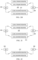
- FIG. 1 depicts an example process of a video delivery pipeline (100) showing various stages from video capture/generation to an HDR or SDR display.
- Example HDR displays may include, but are not limited to, image displays operating in conjunction with TVs, mobile devices, home theaters, etc.
- Example SDR displays may include, but are not limited to, SDR TVs, mobile devices, home theater displays, head-mounted display devices, wearable display devices, etc.
- image processing operations as described herein such as reshaping operations can be performed in either encoder/server side (before video compression) or decoder/playback side (after the video decompression) as well as in a video pre-processing system or block that provides input images for video encoding.
- reshaping operations can be performed in either encoder/server side (before video compression) or decoder/playback side (after the video decompression) as well as in a video pre-processing system or block that provides input images for video encoding.
- the same system configuration depicted in FIG. 1 and different system configurations in addition to what is depicted in FIG. 1 may be used.
- a wide variety of different image metadata formats other than what is used by processing components as depicted in FIG. 1 may be used to convey image metadata in these system configurations.
- Video frames such as a sequence of consecutive input (e.g., SDR, HDR, etc.) images 102 can be received by an image generation block 105.
- These images (102) may be received from a video source, generated by a video pre-processing system/block external or internal to the image generation block (105), or retrieved from a video data store.
- Some or all of the images (102) can be generated from source images, for example through (e.g., automatic with no human input, manual, automatic with human input, etc.) video editing or transformation operations, color grading operations, etc.
- the source images may be digitally captured (e.g. by a digital camera), generated by converting analog camera pictures captured on film to a digital format, generated by a computer (e.g. using computer animation, image rendering, etc.), and so forth.
- the images (102) may be images relating to one or more of: movie releases, archived media programs, media program libraries, video recordings/clips, media programs, TV programs, user-generated video contents, etc.
- the image generation block (105) applies (e.g., local, global, local and global, etc.) reshaping operations to each input image in the sequence of consecutive input images (102) to generate a respective (e.g., reshaped, reconstructed, enhanced, further enhanced, etc.) output image in a sequence of corresponding consecutive (e.g., reshaped, reconstructed, enhanced, further enhanced, etc.) output images that depict the same visual semantic content as the input images (102) but with the same or a different dynamic range, higher local contrasts, more vivid colors, etc., in comparison with the input images (102).
- the image generation block (105) can select or construct global reshaping functions 142 and/or local reshaping functions 146 general or specific to the input image.
- the image generation block (105) can perform global reshaping operations based on the global reshaping functions (142) and/or perform local reshaping operations based on the local reshaping functions (146) to reshape or convert the input image into a corresponding output (e.g., reshaped, reconstructed, enhanced, further enhanced, etc.) image depicting the same visual semantic information as the input image.
- the image generation block (105) can perform global reshaping operations alone, local reshaping operations alone or a combination of global and/or local reshaping operations, and so on, to generate the corresponding output image from the input image.
- the output image may of the same or different dynamic range, higher local contrasts, more vivid colors, etc., as compared with the input image.
- some of the reshaping operations can be performed offline to generate pre-built reshaping mappings/functions based on training image data such as training HDR images, training SDR images, combinations/pairs of training HDR-SDR images, etc.
- pre-built reshaping mappings/functions can be used or adapted directly or indirectly for the purpose of performing dynamic online reshaping operations in the image generation block (105) at runtime.
- the output images generated by the image generation block (105) can be provided to a composer metadata generation block 115 to generate forward reshaped SDR images 112 as well as to generate image metadata 177 (e.g., composer metadata, backward reshaping mappings, etc.).
- the image metadata (177) may include composer data to generate backward reshaping mappings which when applied to a forward reshaped SDR image generate a corresponding HDR image depicting the same visual semantic content as the forward reshaped SDR image.
- Some or all of the input images (102) can be provided to the composer metadata generation block (115) to facilitate or support forward reshaping operations that generate the forward reshaped SDR images (112) as well as facilitate or support generation of the image metadata or the backward reshaping mappings therein.
- TPB operations are described in U.S. Provisional Application Ser. No. 62/908,770 (Attorney Docket No. 60175-0417), titled “TENSOR-PRODUCT B-SPLINE PREDICTOR,” filed on October 1, 2019 , the entire contents of which are incorporated by reference in its entirety as if fully set forth herein.
- the reshaped SDR images (112) and the image metadata (177) may be encoded by a coding block 120 in a video signal 122 (e.g., a coded bitstream, etc.) or a set of consecutive video segments.
- a recipient device such as a mobile phone can decide - as a part of internally processing or post-processing the video signal (122) on the device - to use the metadata along with the SDR image data to generate and render images with higher dynamic range such as HDR and more vivid color within display capabilities of the recipient device.
- the video signal (122) or video segments allow backwards compatibility with legacy SDR displays which can ignore the image metadata (177) and simply display SDR images represented in the SDR image data.
- Example video signals or video segments may include, but are not necessarily limited to, single layer video signals/segments, etc.
- the coding block (120) may comprise audio and video encoders, such as those defined by ATSC, DVB, DVD, Blu-Ray, and other delivery formats, to generate the video signal (122) or video segments.
- the video signal (122) or video segments are then delivered downstream to receivers such as mobile devices, tablet computers, decoding and playback devices, media source devices, media streaming client devices, television sets (e.g., smart TVs, etc.), set-top boxes, movie theaters, and the like.
- the video signal (122) or video segments are decoded by decoding block (130) to generate decoded images 182, which may be similar to or the same as the reshaped SDR images (112) subject to quantization errors generated in compression performed by the coding block (120) and decompression performed by the decoding block (130) and/or transmission errors and/or synchronization errors and/or errors caused by packet loss.
- the video signal (122) may be backward compatible SDR video signal (or video segments).
- a "backward compatible” refers to a video signal or video segments that carry SDR images optimized (e.g., with specific artistic intent preserved, etc.) for SDR displays.
- the decoding block (130) can also retrieve or decode the image metadata (177) from the video signal (122) or video segments.
- the image metadata (177) specifies backward reshaping mappings that can be used by the downstream decoders to perform backward reshaping on the decoded SDR images (182) to generate backward reshaped HDR images for rendering on an HDR (e.g., target, reference, etc.) display.
- the backward reshaping mappings represented in the image metadata (177) may be generated by the composer metadata generation block (115) through minimizing errors or differences between the backward reshaped HDR images generated with the image metadata (177) and the output images generated by the image generation block (115) with the global and/or local reshaping operations.
- the image metadata (177) helps ensure that the backward reshaped HDR images generated with the image metadata (177) by the receiver relatively closely and accurately approximate the output images generated by the image generation block (115) with the global and/or local reshaping operations.
- the image metadata (177) may include display management (DM) metadata that can be used by the downstream decoders to perform display management operations on the backward reshaped images to generate display images (e.g., HDR display images, etc.) optimized for rendering on an HDR display device.
- DM display management
- the receiver can render the decoded SDR images directly or indirectly on the target display (140).
- the receiver can extract the composer metadata from (e.g., the metadata container in, etc.) the video signal (122) or video segments and use the composer metadata to compose HDR images (132), which may be backward reshaped images generated from backward reshaping the SDR images based on the composer metadata.
- the composer metadata e.g., the metadata container in, etc.
- the video signal (122) or video segments can extract the composer metadata from (e.g., the metadata container in, etc.) the video signal (122) or video segments and use the composer metadata to compose HDR images (132), which may be backward reshaped images generated from backward reshaping the SDR images based on the composer metadata.
- the receiver can extract the DM metadata from the video signal (122) or video segments and apply DM operations (135) on the HDR images (132) based on the DM metadata to generate display images (137) optimized for rendering on the HDR display device (140-1) and render the display images (137) on the HDR display device (140-1).
- global and/or local reshaping operations as described herein can be performed by an upstream device such as a video encoder to generate output images from input images. These output images are then used as target or reference images by the video encoder to generate backward reshaping metadata that helps recipient devices generate backward reshaped HDR images that relatively closely or accurately approximates the output images generated from the global and/or local reshaping operations.
- an upstream device such as a video encoder to generate output images from input images.
- These output images are then used as target or reference images by the video encoder to generate backward reshaping metadata that helps recipient devices generate backward reshaped HDR images that relatively closely or accurately approximates the output images generated from the global and/or local reshaping operations.
- some or all global and/or local reshaping operations can be performed by a video encoder alone, a video decoder alone, a video transcoder alone, or a combination of the foregoing.
- FIG. 2A illustrates an example architecture for applying global and/or local reshaping operations. Some of all the reshaping operations may be implemented or performed by an image processing system such as one or more processing blocks of FIG. 1 on the encoder side, one or more processing blocks of FIG. 1 on the encoder side, a combination of processing blocks of FIG. 1 on the encoder and decoder side, and so on.
- an image processing system such as one or more processing blocks of FIG. 1 on the encoder side, one or more processing blocks of FIG. 1 on the encoder side, a combination of processing blocks of FIG. 1 on the encoder and decoder side, and so on.
- block 202 represent an HDR video signal input/output interface.
- the HDR video signal input/output interface (202) may be an HDR video signal input interface alone, an HDR video signal output interface alone, or a combination of an HDR video signal input interface and an HDR video signal output interface.
- an input HDR video signal or input HDR images therein may be inputted or received with an HDR video input interface of the HDR video signal input/output interface (202).
- an output HDR video signal or output HDR images therein may be outputted or sent with an HDR video output interface of the HDR video signal input/output interface (202).
- block 208 represent an SDR video signal input/output interface.
- the SDR video signal input/output interface (208) may be an SDR video signal input interface alone, an SDR video signal output interface alone, or a combination of an SDR video signal input interface and an SDR video signal output interface.
- an input SDR video signal or input SDR images therein may be inputted or received with an SDR video input interface of the SDR video signal input/output interface (208).
- an output SDR video signal or output SDR images therein may be outputted or sent with an SDR video output interface of the SDR video signal input/output interface (208).
- Blocks 204 and 206 represent options for forward reshaping operations, methods and/or functions in a forward reshaping path.
- Blocks 210 and 212 represent options for backward reshaping operations, methods and/or functions in a backward reshaping path.
- Each of the forward and backward reshaping path comprises options for global reshaping operations, methods and/or functions that may be designed to maintain overall (SDR or HDR) look(s) of SDR or HDR image(s) generated by these global reshaping operations, methods and/or functions.
- the forward global reshaping operations, methods and/or functions in the forward reshaping path form a (e.g., fully, faithfully, subject to quantization errors, etc.) revertible reshaping pair with the backward global reshaping operations, methods and/or functions in the backward reshaping path.
- an (e.g., input, received, etc.) HDR image is forward reshaped by the forward global reshaping operations, methods and/or functions in the forward reshaping path to generate a forward reshaped (e.g., SDR, etc.) image
- a reconstructed or backward reshaped image generated by applying the backward global reshaping operations, methods and/or functions in the backward reshaping path is the same as the (e.g., input, received, etc.) HDR image or closely approximates the (e.g., input, received, etc.) HDR image subject to possible quantization errors.
- an (e.g., input, received, etc.) SDR image is backward reshaped by the backward global reshaping operations, methods and/or functions in the backward reshaping path to generate a backward reshaped (e.g., HDR, etc.) image
- a reconstructed or forward reshaped image generated by applying the forward global reshaping operations, methods and/or functions in the forward reshaping path is the same as the (e.g., input, received, etc.) SDR image or closely approximates the (e.g., input, received, etc.) SDR image subject to possible quantization errors.
- local reshaping operations, methods and/or functions in the forward or backward path - in contrast to the global reshaping operations, methods and/or functions - may not be revertible by, or may not form a revertible pair with, other global or local reshaping operations in the backward or forward path.
- an input video signal or input images therein can be HDR or SDR.
- an output video signal or output (e.g., reconstructed, etc.) images therein can be HDR or SDR.
- the input signal is an HDR input signal
- the output signal is an HDR output signal.
- an input HDR image in the HDR input signal is processed by forward reshaping first followed by backward reshaping to generate a corresponding output HDR image (depicting the same visual semantic content as the input HDR image) in the HDR output signal.
- There are four (2*2 4) combinations formed by two options of using either global or local reshaping in the forward path times two options of sing either global or local reshaping in the backward path.
- the input signal is an HDR input signal
- the output signal is an SDR output signal.
- an input HDR image in the HDR input signal is processed by forward reshaping to generate a corresponding output SDR image (depicting the same visual semantic content as the input HDR image) in the SDR output signal.
- the input signal is an SDR input signal
- the output signal is an HDR output signal.
- an input SDR image in the SDR input signal is processed by backward reshaping to generate a corresponding output HDR image (depicting the same visual semantic content as the input SDR image) in the HDR output signal.
- the input signal is an SDR input signal
- the output signal is an SDR output signal.
- an input SDR image in the SDR input signal is processed by backward reshaping first followed by forward reshaping to generate a corresponding output SDR image (depicting the same visual semantic content as the input SDR image) in the SDR output signal.
- There are four (2*2 4) combinations formed by two options of using either global or local reshaping in the backward path times two options of sing either global or local reshaping in the forward path.
- a number of combinations as discussed above can be used to support HDR enhancement in an output HDR video signal reshaped from an input HDR video signal.
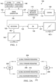
- FIG. 2B illustrates an example of generating an output HDR video signal from an input HDR video signal with global reshaping operations, methods and/or functions in both forward and backward paths.
- an input HDR image in the input HDR video signal received via an input HDR interface of the HDR input/output interface (202) may be converted into an output HDR image in the output HDR video signal sent via an output HDR interface of the HDR input/output interface (202) with the global forward reshaping (204) in the forward path and the global backward reshaping (210) in the backward path.
- the output HDR image is identical to the (original) input HDR image (possibly subject to quantization errors) with no HDR enhancement.
- a reshaped SDR image generated from performing the global forward reshaping (204) on the input HDR image may be a watchable non-enhanced SDR image.
- the output HDR image is changed from the (original) input HDR image with a different HDR look.
- the global forward reshaping (204) in the forward path and the global backward reshaping (210) in the backward path can be used to generate the different HDR look with different brightness and saturation from brightness and saturation in the (original) look of the input HDR image.
- a reshaped SDR image generated from performing the global forward reshaping (204) on the input HDR image can be a watchable non-enhanced SDR image.
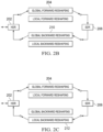
- FIG. 2C illustrates an example of generating an output HDR video signal from an input HDR video signal with global forward reshaping operations, methods and/or functions in the forward path and local backward reshaping operations, methods and/or functions in the backward path.
- an input HDR image in the input HDR video signal received via an input HDR interface of the HDR input/output interface (202) may be converted into an output HDR image in the output HDR video signal sent via an output HDR interface of the HDR input/output interface (202) with the global forward reshaping (204) in the forward path and the local backward reshaping (212) in the backward path.
- the output HDR image is enhanced owing to the use of local backward reshaping.
- a reshaped SDR image generated by performing the global forward reshaping (204) on the input HDR image can be a non-local enhanced SDR image.
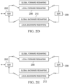
- FIG. 2D illustrates an example of generating an output HDR video signal from an input HDR video signal with local forward reshaping operations, methods and/or functions in the forward path and global backward reshaping operations, methods and/or functions in the backward path.
- an input HDR image in the input HDR video signal received via an input HDR interface of the HDR input/output interface (202) may be converted into an output HDR image in the output HDR video signal sent via an output HDR interface of the HDR input/output interface (202) with the local forward reshaping (206) in the forward path and the global backward reshaping (210) in the backward path.
- the output HDR image is enhanced owing to the use of local forward reshaping.
- a reshaped SDR image generated by performing the local forward reshaping (206) on the input HDR image is a local enhanced SDR image.
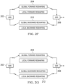
- FIG. 2E illustrates an example of generating an output HDR video signal from an input HDR video signal with local forward reshaping operations, methods and/or functions in the forward path and local backward reshaping operations, methods and/or functions in the backward path.
- an input HDR image in the input HDR video signal received via an input HDR interface of the HDR input/output interface (202) may be converted into an output HDR image in the output HDR video signal sent via an output HDR interface of the HDR input/output interface (202) with the local forward reshaping (206) in the forward path and the local backward reshaping (212) in the backward path.
- the output HDR image is doubly enhanced owing to the use of local forward reshaping and local backward reshaping in both forward and backward paths.
- a reshaped SDR image generated by performing the local forward reshaping (206) on the input HDR image is an enhanced SDR.
- global settings in one or both of the forward and backward paths can be asymmetric, thereby further changing the (original) HDR look of the input HDR image into a different HDR look of different global brightness and saturation as compared with the input HDR image.
- some or all of the foregoing operations in a combination of one or more options as discussed above can be iteratively performed in multiple round of global/local forward and global/local backward reshaping for generating further HDR and/or SDR enhancement in the output HDR image and the reshaped SDR image.
- a number of combinations as discussed above can be used to support SDR enhancement in an output SDR video signal reshaped from an input SDR video signal.
- FIG. 2F illustrates an example of generating an output SDR video signal from an input SDR video signal with global reshaping operations, methods and/or functions in both forward and backward paths.
- an input SDR image in the input SDR video signal received via an input SDR interface of the SDR input/output interface (208) may be converted into an output SDR image in the output SDR video signal sent via an output SDR interface of the SDR input/output interface (208) with the global forward reshaping (204) in the forward path and the global backward reshaping (210) in the backward path.
- the output SDR image is identical to the (original) input SDR image (possibly subject to quantization errors) with no SDR enhancement.
- a reshaped HDR image generated from performing the global backward reshaping (210) on the input SDR image may be a watchable non-enhanced HDR image.
- the output SDR image is changed from the (original) input SDR image with a different SDR look.
- the global forward reshaping (204) in the forward path and the global backward reshaping (210) in the backward path can be used to generate the different SDR look with different brightness and saturation from brightness and saturation in the (original) look of the input SDR image.
- a reshaped HDR image generated from performing the global backward reshaping (210) on the input SDR image can be a watchable non-enhanced HDR image.
- FIG. 2G illustrates an example of generating an output SDR video signal from an input SDR video signal with global forward reshaping operations, methods and/or functions in the forward path and local backward reshaping operations, methods and/or functions in the backward path.
- an input SDR image in the input SDR video signal received via an input SDR interface of the SDR input/output interface (208) may be converted into an output SDR image in the output SDR video signal sent via an output SDR interface of the SDR input/output interface (208) with the global forward reshaping (204) in the forward path and the local backward reshaping (212) in the backward path.
- the output SDR image is enhanced owing to the use of local backward reshaping.
- a reshaped HDR image generated by performing the global backward reshaping (212) on the input SDR image can be a local enhanced HDR image.
- FIG. 2H illustrates an example of generating an output SDR video signal from an input SDR video signal with local forward reshaping operations, methods and/or functions in the forward path and global backward reshaping operations, methods and/or functions in the backward path.
- an input SDR image in the input SDR video signal received via an input SDR interface of the SDR input/output interface (208) may be converted into an output SDR image in the output SDR video signal sent via an output SDR interface of the SDR input/output interface (208) with the local forward reshaping (206) in the forward path and the global backward reshaping (210) in the backward path.
- the output SDR image is enhanced owing to the use of local forward reshaping. Additionally, optionally or alternatively, a reshaped HDR image generated by performing the global backward reshaping (210) on the input SDR image can be a non-local enhanced HDR image.
- FIG. 2I illustrates an example of generating an output SDR video signal from an input SDR video signal with local forward reshaping operations, methods and/or functions in the forward path and local backward reshaping operations, methods and/or functions in the backward path.
- an input SDR image in the input SDR video signal received via an input SDR interface of the SDR input/output interface (208) may be converted into an output SDR image in the output SDR video signal sent via an output SDR interface of the SDR input/output interface (208) with the local forward reshaping (206) in the forward path and the local backward reshaping (212) in the backward path.
- the output SDR image is doubly enhanced owing to the use of local forward reshaping and local backward reshaping in both forward and backward paths.
- a reshaped HDR image generated by performing the local backward reshaping (212) on the input SDR image is an enhanced HDR.
- global settings in one or both of the forward and backward paths can be asymmetric, thereby further changing the (original) SDR look of the input SDR image into a different SDR look of different global brightness and saturation as compared with the input SDR image.
- some or all of the foregoing operations in a combination of one or more options as discussed above can be iteratively performed in multiple round of global/local forward and global/local backward reshaping for generating further HDR and/or SDR enhancement in the output SDR image and the reshaped HDR image.
- FIG. 2J illustrates an example video application in which source images are captured as SDR images by a mobile device in an input SDR video signal.
- An SDR to HDR up-conversion may be implemented or performed with global backward reshaping (e.g., 210, etc.).
- Upconverted (or reshaped) HDR images with at least dynamic range enhancement can be generated by performing the global backward reshaping (210) on the (source or input) SDR images.
- the global backward reshaping (210) can be used to generate the (upconverted or reshaped) HDR images.
- the HDR images can be encoded as an output version of an HDR coded bitstream. This version of the HDR coded bitstream can be shared, previewed and/or displayed on a display screen of the mobile device.
- the HDR images can be uploaded by way of the HDR coded bitstream to another device (e.g., a PC, a laptop, a cloud-based storage and/or computing system, a server, a media or video sharing system, etc) such as a more powerful machine.
- the HDR coded bitstream can be received as an input HDR video signal.
- the HDR images of the version of the HDR coded bitstream - as generated from the global backward reshaping (210) performed by the mobile device on the (original) SDR images - can be further enhanced by first using revertible global forward reshaping (204) - which forms a revertible pair or corresponds to the global backward reshaping (210) of FIG.
- local backward reshaping (212) can be applied or performed on the recovered SDR images to generate (new) HDR images with an enhanced HDR look as compared with the HDR look of the HDR images of the version of the HDR coded bitstream.
- the original or input SDR images can be recovered - from the HDR images of the version of the HDR coded bitstream generated by the mobile device - and viewed.
- HDR images with at least dynamic range enhancement generated by the mobile device can be received - e.g., from the mobile device - and viewed.
- HDR images with further enhancement can be generated - from performing local reshaping as described herein such as illustrated in FIG. 2C - and viewed.
- global forward reshaping can be performed on the HDR images to generate output SDR images.
- the output SDR images can be reverted back to the (original) input HDR images using global backward reshaping that forms a revertible pair or corresponds to the global forward reshaping.
- local forward reshaping can be performed on the HDR images to generate enhanced output SDR images, for example with local enhancement
- global reshaping functions or mappings used in global reshaping can be designed based on a scalable static framework for single-layer backward compatible (SLBC) video coding.
- An algorithm that ensures full revertability from one domain such as one of SDR and HDR domains to another domain such as the other of the SDR and HDR domains can be used in global reshaping as described herein.
- Different usages of global reshaping exist depending on whether forward and backward (global reshaping) functions used by the global reshaping form a revertible pair or not.
- paired forward and backward global reshaping functions are used in the scalable static framework for SLBC video encoding.
- G a total number of fully revertible global forward and global backward reshaping function pairs.
- Each of the fully revertible global forward and global backward reshaping function pairs comprises a global forward reshaping function and a corresponding global backward reshaping function.
- each of the global backward reshaping functions converts or forward reshapes codewords for luma and chroma channels of the second color space to backward reshaped codewords for luma and chroma channels of the first color space
- the luma global forward reshaping functions may be indexed or looked up using different index values g F,Y .
- the luma global backward reshaping functions may be indexed or looked up using different index values g B,Y .
- a revertible pair - in a plurality of revertible pairs formed by the global forward reshaping functions in expressions (1) and the global backward reshaping functions in expressions (2) - may be formed by a global forward reshaping function in the global forward reshaping functions in expressions (1) and a global backward reshaping function (in the global backward reshaping functions in expressions (2)) corresponding to the global forward reshaping function.
- the global forward reshaping function and the global backward reshaping function in the same revertible pair may be indexed with the same index value.
- the same pair of global forward and global backward reshaping functions can be used to recover an original input video signal or an input image therein in an output video signal or an output image.
- RHS right hand side
- LHS left hand side
- Quantization errors or losses can occur when a reshaping function makes a bit depth conversion from a pre-reshaping bit depth (e.g., the total number of bits to code each codewords in a pre-reshaping image in a pre-shaping color space channel, etc.) to a post-reshaping bit depth (e.g., the total number of bits to code each codewords in a post-reshaping image in a post-shaping color space channel, etc.) such as from a 16-bit pre-reshaping video signal/image to a 10-bit post-reshaping video signal/image. If differences between an input image received by a revertible pair and an output image generated by the revertible pair are attributed to quantization errors or losses caused by bit-depth conversion(s), then the input image and the output image may still be deemed as the same.
- a pre-reshaping bit depth e.g., the total number of bits to code each codewords in
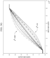
- the input to output codeword mapping in the luma channel is almost a linear line (e.g., within the SMPTE specified range that clips at both ends of a defined luma value range, etc.).
- FIG. 3D and FIG. 3E illustrate example chroma codeword mapping using the same (revertible) pair of global forward and backward reshaping functions indexed by the same index value g for converting input chroma codewords of an input HDR image (16 bits) into output chroma codewords of an output HDR image (16 bits) using expression (3-2) above.
- the input chroma codewords may form a group of colors with fixed Cb (e.g., 35000, etc.) and Cr (e.g., 28000, etc.) values but with varying luma codeword values.
- the input-to-output codeword mapping in the chroma channel for this group of colors is almost a linear line. This implies chroma codewords reconstructed or outputted in the output HDR image generated by the revertible pair is the same as, or very close to, chroma codewords received in the input HDR image with respect to this group of colors for the varying luma codeword values.
- Another group of colors with another set of fixed Cb and Cr codeword values (e.g., Cb as 25000 and Cr as 35000, etc.) but with varying luma codeword values can be used in chroma mapping using the revertible pair of the global forward and backward reshaping functions. It can be shown that the input-to-output codeword mapping in the chroma channel for such other group of colors is almost a linear line, similar to FIG. 3D and FIG. 3E .
- chroma codewords reconstructed or outputted in the output HDR image generated by the revertible pair is the same as, or very close to, chroma codewords received in the input HDR image with respect to the other group of colors for the varying luma codeword values.
- the input to output codeword mapping in the luma channel is almost a linear line (e.g., within an entire codeword range as specified in an industry standard, etc.). This implies luma codewords reconstructed or outputted in the output SDR image generated by the revertible pair is the same as, or very close to, luma codewords received in the input SDR image.
- chroma codeword mapping can be performed with the revertible pair to map input SDR chroma codewords in the input SDR image to output SDR chroma codewords in the output SDR image.
- the global forward and backward reshaping functions in the revertible pair may be, but are not necessarily limited to only, MMR based forward and backward mappings/functions for chroma mapping and FLUT/BLUT based forward and backward mappings/functions for luma mapping.
- An MMR based backward mapping/function in the revertible pair may be used to map input luma and chroma codewords in the input SDR image into backward reshaped chroma codewords in a backward reshaped HDR image.
- a BLUT based backward mapping/function in the revertible pair may be used to map input luma codewords in the input SDR image into backward reshaped luma codewords in the backward reshaped HDR image.
- An MMR based forward mapping/function in the revertible pair may be used to map backward reshaped luma and chroma codewords in the backward reshaped HDR image into output chroma codewords in the output SDR image.
- a FLUT based forward mapping/function in the revertible pair may be used to map backward reshaped luma codewords in the backward reshaped HDR image into output luma codewords in the output SDR image.
- input chroma codewords in the output SDR image can be recovered, or can be the same as, the output chroma codewords in the input SDR image in the input-SDR-output-SDR conversion implemented with the revertible pair, subject to possible quantization errors.
- Reshaping functions from different revertible pairs may not reproduce an input video signal (or an input image therein) in an output signal (or an output image therein) generated from reshaping operations performed on the input video signal (or the input image therein) based on these functions.
- forward luma and chroma reshaping functions may be indexed by first index values g F,Y and g F,C x , respectively, where the first index values may or may not equal each other.
- backward luma and chroma reshaping functions may be indexed by second index values g B,C and g B,C x , respectively, where the second index values may or may not each other.
- an input video signal (or an input image therein) may not be reproduced in an output signal (or an output image therein) generated from reshaping operations performed on the input video signal (or the input image therein) based on these functions, as follows.
- these reshaping functions which may be referred to as unpaired forward and backward reshaping functions, can be applied, or used as a tool, to adjust input brightness and saturation of an input image into different brightness and saturation of an output image as global image enhancement.
- index values are selected such that g B,Y > g F,Y , then a reconstructed HDR image generated at least in part by performing the luma forward and backward reshaping functions with these index values on an input HDR image become brighter than the input HDR image.
- the index values are selected such that g B,Y ⁇ g F,Y , then a reconstructed HDR image generated at least in part by performing the luma forward and backward reshaping functions with these index values on an input HDR image become darker than the input HDR image.
- index values are selected such that g B,C x > g F,C x , where may be Cb or Cr, then a reconstructed HDR image generated at least in part by performing the chroma forward and backward reshaping functions with these index values on an input HDR image become more saturated than the input HDR image.
- the index values are selected such that g B,C x ⁇ g F,C x , then a reconstructed HDR image generated at least in part by performing the chroma forward and backward reshaping functions with these index values on an input HDR image become less saturated than the input HDR image.
- a gap between the two index values, ⁇ g C x g B,C x - g F,C x affects the saturation change.
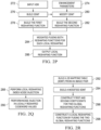
- FIG. 2K illustrates an example flow using unpaired forward and backward reshaping functions to change brightness and/or saturation of an input video signal to different brightness and/or saturation of an output video signal.
- the flow of FIG. 2K may be performed by one or more computing devices such as a video encoder, a video transcoder, a video decoder, or a combination of the foregoing.
- the input video signal and the output video signal are an input HDR video signal and an output HDR video signal, respectively.
- Block 222 comprises receiving an input HDR image in the input HDR video signal.
- Blocks 224-1 and 224-2 comprise selecting first luma and chroma index values for forward reshaping functions.
- Blocks 226-1 and 226-2 comprise performing luma and chroma forward reshaping on the input HDR image based on luma and chroma forward reshaping functions indexed by the first index values to generate a forward reshaped image.
- Blocks 228-1 and 228-2 comprise selecting second luma and chroma index values for backward reshaping.
- Blocks 230-1 and 230-2 comprise performing luma and chroma backward reshaping on the forward reshaped image based on luma and chroma backward reshaping functions indexed by the second index values to generate a reconstructed HDR image with different brightness and/or different saturation from that of the input HDR image.
- Block 232 comprises outputting the reconstructed HDR image.
- FIG. 2L illustrates an example luma and chroma local reshaping 246 that can be performed on an input image 242 to generate a (locally reshaped) output image 250.
- Processing blocks of FIG. 2L - including but not limited to the luma and chroma local reshaping (246) - may be implemented or performed by one or more computing devices such as a video encoder, a video transcoder, a video decoder, or a combination of the foregoing.
- two components may be used to assist or support the luma and chroma local reshaping (246).
- the first component is a local reshaping function family 248 comprising a collection (or a total number L ) of local reshaping functions denoted as F ⁇ l > ( ), where l is 0, 1, ... L -1.
- F ⁇ l > ( ) local reshaping functions
- the local reshaping function family comprises a luma local reshaping function family denoted as F ⁇ l > Y for luma local reshaping and a chroma local reshaping function family denoted as F ⁇ l > c x for chroma local reshaping.
- the guided image, M contains an individual (reshaping function) index value (in a value range of [0 L -1]) for each input pixel in some or all of the input image (242) to select which local reshaping function in the local reshaping function family to perform local reshaping on the input pixel to generate a corresponding output pixel in the output image (250).
- the guided image, M can comprise different guided images, such as M Y and M C x for luma and chroma local reshaping in different luma and chroma channels.
- the local reshaping (246) can look up specific reshaping function index value(s) stored - at the same row and same column as an image frame containing the input image (242) - in the guided image.
- the specific reshaping function index value(s) can then be used to select or identify specific local reshaping function(s) among the reshaping functions constituting the reshaping function family (248).
- the specific local reshaping function(s) can then be used to perform the luma and chroma local reshaping on the input pixel to generate a corresponding output pixel in the output image (250).
- output or reshaped luma codewords of an output image can be generated from performing single-channel luma local reshaping on input or pre-reshaped luma codewords of an input image. More specifically, an input luma codeword (e.g., sufficiently, etc.) for a pixel of the input image enables a local reshaping function to determine a mapped or reshaped luma codeword of a corresponding pixel of the output image, without using input chroma codewords for the pixel of the input image.
- an input luma codeword e.g., sufficiently, etc.
- a luma local reshaping (function) family for single-channel luma local reshaping can be generated in a number of different ways.
- self-derived local reshaping may be used to generate a luma local reshaping family.
- the self-derived local reshaping refers to an approach under which the luma local reshaping family is derived from a luma global reshaping function.
- This (type of) luma local reshaping function family can be generated on the fly at runtime in response to each input image or a specific codeword distribution therein.
- the local reshaping function family may comprise luma local reshaping functions customized for each frame in different content.
- offline training may be used to generate a luma local reshaping family comprising pre-built luma local reshaping functions.
- This (type of) luma local reshaping function family may be applied to all input images in all content.
- hybrid offline and online operations may be used to generate a luma local reshaping family comprising luma local reshaping functions generated by performing some or all of the self-derived local reshaping from the pre-built global reshaping functions.
- Benefits of this hybrid method is to save or reduce computational costs in that luma reshaping functions can be built using a dynamic global function constructed in response to an input image at runtime and the pre-built local functions generated from training offline.
- Two goals of luma local reshaping are to (a) increase local contrast ratio (2) while maintaining similar brightness in an output image generated from performing the luma local reshaping on an input image.
- the first goal can be achieved by increasing slopes of local reshaping functions such as those represented with tone curves.
- the second goal as mentioned above can be achieved by intersecting the (e.g., new, etc.) local reshaping functions with a global reshaping function at various locations.
- Example generation of local reshaping functions given a global reshaping function is described in U.S. Provisional Application Ser. No. 63/004,609, titled "BLIND LOCAL RESHAPING IN HDR IMAGING," filed on Apr 3, 2020 , the entire contents of which are incorporated by reference in its entirety as if fully set forth herein.
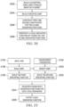
- FIG. 2M illustrates an example flow for self-derived local function generation from a global reshaping function denoted as F ().
- the global reshaping function can be computed by a video codec in online operations, for example in response to receiving an input image for local reshaping.
- a global shaping function may be referred to as a (e.g., adaptive, runtime, etc.) dynamic global reshaping function.
- the global reshaping function can be computed or pre-built by an image processing system in offline operations, for example not necessarily in response to receiving an input image for local reshaping.
- Such a global shaping function may be referred to as a (e.g., scalable, pre-configured, etc.) static global reshaping function.
- Block 252 comprises building a template reshaping function.
- flat areas in the global reshaping function F () may be removed first to generate a modified reshaping curve or function.
- These flat areas may correspond sub-ranges outside an entire range of (e.g., valid, SMPTE, etc.) available codewords in a codeword space.
- the flat areas may be added back later in (e.g., finally, etc.) constructed local reshaping functions.
- the modified reshaping curve or function can then be shifted until it touches the y-axis.
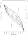
- a plot or curve representing a local or global reshaping function e.g., as illustrated in FIG. 3A , FIG. 3B , FIG. 3G and FIG. 3H , etc.
- a plot or curve representing a local or global reshaping function may be represented in a two-dimensional coordinate system in which the y-axis represents reshaped or output codewords while the x-axis represents pre-reshaped or input codewords.
- the shifting of the modified reshaping curve or function can be used to avoid or obviate corner case handling and facilitate scaling and shifting operations that generate local reshaping functions.
- an x-axis scaling factor denoted as ⁇ ⁇ l >
- ⁇ ⁇ l > an x-axis scaling factor
- a local neighborhood around the input codeword value along the x-axis is (e.g., proportional to the x-axis scaling factor, etc.) expanded thereby reducing or decreasing local contrast ratio (or increasing blur) at an x-axis location represented by the input codeword value.
- the x-axis scaling factor ⁇ ⁇ l> is greater than one (1), the curve is expanded along the x-axis.
- the x-axis expanded curve has a smaller slope than the pre-expanded curve, thereby reducing the contrast ratio in the x-axis expanded curve as compared with the pre-expanded curve.
- the local neighborhood around the input codeword value along the x-axis may be (e.g., proportional to the x-axis scaling factor, etc.) compressed thereby increasing or enhancing the local contrast ratio (or sharpness) at the x-axis location represented by the input codeword value.
- the x-axis scaling factor ⁇ ⁇ l > is less than one (1), the curve is compressed along the x-axis.
- the x-axis compressed curve has a higher slope than the pre-compressed curve, thereby increasing the contrast ratio in the x-axis compressed curve as compared with the pre-compressed curve.
- the x-axis scaling factor ( ⁇ ⁇ l> ⁇ 1) can be used to scale - e.g., along the x-axis as specified by the x-axis scaling factor - the shifted modified reshaping function at various input codeword values to generate a scaled (forward) function to increase local contrast ratio (or sharpness) in the scaled function at these input codeword values.
- unequal local contrast ratio enhancement can be achieved among different local reshaping functions in the local reshaping family by using different values of the x-axis scaling factor in expression (8) above for different l values of the local reshaping functions.
- equal local contrast ratio enhancement can be achieved among some or all local reshaping functions in the local reshaping family by using the same value of the x-axis scaling factor in expression (8) above for l values of the local reshaping functions.
- only one scaled and resampled function may be built from the global reshaping function with the same x-axis scaling factor ⁇ ⁇ l> in expression (8) above as the template reshaping function for all the local reshaping functions.
- Block 254 comprises shifting the template reshaping functions in expression (8) above to generate a pre-fusing local reshaping function that can be fused with the global reshaping function into the l-th local reshaping function in the local reshaping family.
- This shifting of the template reshaping function achieves the second goal, namely maintaining similar (e.g., locally average, locally filtered, global, etc.) brightness between the pre-fusing local reshaping functions and the global reshaping function.
- the mixing of functions comprises calculating a linear combination of the involved functions.
- the weights in the linear combination may be normalized to a given value. For example, the sum of weights may be 1.
- pre-fusing used throughout this disclosure is used in conjunction with reshaping functions.
- a local reshaping function may be fused with a global reshaping function.
- the resulting fused reshaping function is still a local reshaping function despite its fusion with a global reshaping function, as the fused reshaping function still maintains the different functional characteristic on the pixel level from the pre-fusing local reshaping function.
- an initial local reshaping function prior to fusing is referred to as "pre-fusing local reshaping function"
- the fused result is referred to as "post-fusing local reshaping function", "fused local reshaping function” or simply "local reshaping function”.
- pre-fusing may also be applied to other reshaping functions, e.g. when fusing two global reshaping functions that further remain global and therefore need distinction whether the global reshaping function prior to fusing ("pre-fusing") or after fusing is to be addressed.
- an input pixel such as the i-th input codeword in the input image can be reshaped into an output pixel such as the i-th output codeword with the pre-fusing local reshaping function for the l-th local reshaping function indexed - in the local reshaping family - by a corresponding local reshaping function index value l stored in the i-th element (denoted as m i ) of the guided image M .
- bit depth of the input image B v .
- This constraint can be used to determine an amount of shifting or a shift (value) for the pre-fusing local reshaping function F ⁇ l > C l v and apply the shift (value) to the template reshaping function to generate the pre-fusing local reshaping function F ⁇ l > C l v for the l-th local reshaping function, without recomputing the l-th local reshaping function or the pre-fusing local reshaping function F ⁇ l > C l v from scratch.
- a corresponding mapped (or globally reshaped) value F C l v may be obtained or looked up (e.g., from a curve, a function and/or a lookup table representing the global reshaping function F C l v , etc.).
- the template reshaping function or local reshaping functions generated from the template reshaping function may generate out-of-range values that would be hard clipped with the range of allowable codeword values, thereby possibly generating visual artifacts.
- soft clipping may be used by fusing the global and local functions together with respective weighting factors.
- Block 256 comprises soft clipping the pre-fusing local reshaping function F ⁇ l > C l v by fusing the pre-fusing local reshaping function F ⁇ l > C l v with the global reshaping function.
- a global reshaping function weighting factor denoted as ⁇ ⁇ l > Y , G and a local reshaping function weighting factor denoted as ⁇ ⁇ l > Y , L may be respectively assigned to the global reshaping function and the pre-fusing local reshaping function F ⁇ l > C l v for the l-th local reshaping function.
- a plurality of pre-built single-channel global reshaping functions F ⁇ g > Y ( ) respectively indexed by global reshaping function index values denoted as g can be obtained through offline training.
- a hybrid approach combining pre-defined and self-derived single-channel local reshaping may be used to generate local reshaping functions. More specifically, self-derived local reshaping as discussed above can be performed with respect to an existing pre-built global reshaping function, instead of a (e.g., dynamic, etc.) global reshaping function built in response to receiving an input image. For example, based on a codeword distribution of the input image, a specific pre-built global reshaping function may be selected from among a plurality of pre-built global reshaping functions (e.g., obtained through offline training, etc.). The specific pre-built global reshaping function may be used in the self-derived local reshaping as discussed above in place of the global reshaping function built in response to receiving the input image.
- a specific pre-built global reshaping function may be used in the self-derived local reshaping as discussed above in place of the global reshaping
- output or reshaped luma codewords of an output image can be generated from performing cross-channel luma local reshaping on input or pre-reshaped luma and chroma codewords of an input image. More specifically, input luma and chroma codeword (e.g., sufficiently, etc.) for a pixel of the input image collectively enables a (e.g., TPB based, MMR based, etc.) local reshaping mapping to determine a mapped or reshaped luma codeword of a corresponding pixel of the output image.
- a local reshaping mapping to determine a mapped or reshaped luma codeword of a corresponding pixel of the output image.
- a luma local reshaping (function) family for cross-channel luma local reshaping can be generated in a number of different ways. Similar to the single-channel luma local reshaping, the cross-channel luma local reshaping at least includes: (1) using self-derived local reshaping functions, (2) using pre-built reshaping functions, and (3) a hybrid of using both self-derived and pre-build reshaping functions.
- cross-channel luma reshaping functions may be used.
- cross-channel luma reshaping functions may be Tensor-Product B-Spline (TPB) based.
- TPB based reshaping functions are capable of capturing wide non-linearity in luma reshaping.
- FIG. 2N illustrates an example flow for self-derived cross-channel local function generation based on an image pair comprising a first image and a second image.
- a TPB based local reshaping function may be generated with the flow to map input codewords of the first image to locally reshaped codewords approximating or reconstructing codewords of a reference image represented by the second image.
- the first image in the image pair may be an HDR image
- the second image (or reference image) may be an SDR image.
- the SDR image may have been used (e.g., through previously performed content mapping, tone mapping and/or reshaping operations, etc.) to generate the HDR image.
- the SDR image may have been generated (e.g., through previously performed content mapping, tone mapping and/or reshaping operations, etc.) from the HDR image.
- Block 262 comprises constructing or building a 3D mapping table (3DMT) from the image pair.
- the HDR color space comprising available codewords in each of the three channels can be (e.g., uniformly, etc.) quantized or partitioned using a corresponding fixed number - such as Q y , Q C 0 , Q C 1 for each component - of one-dimensional bins.
- a three-dimensional histogram may be initialized to comprise ( Q y ⁇ Q C 0 ⁇ Q C 1 ) cubes or 3D histogram bins.
- the 3D histogram ⁇ Q ,v contains a total number ( Q y .Q C 0 .Q C 1 ) of 3D histogram bins.
- a sum of (e.g., reference, mapped, etc.) codeword values in the SDR image may be computed for each 3D histogram bin in the 3D histogram.
- Let ⁇ y Q , s , ⁇ C 0 Q , s and ⁇ C 1 Q , s be respective sums of codewords in the luma and chroma channels ⁇ y , C 0 , C 1 ⁇ of the output domain. respectively.
- each of the HDR image and the SDR image comprises P pixels.
- An example procedure to compute counts of HDR pixels in, and sums of SDR codeword values for, the 3D histogram bins of the 3D histogram is illustrated in TABLE 1 below.
- 3D histogram bins that have non-zero total numbers of pixels can be identified. All other 3D histogram bins that do not have any pixels - or that have total numbers of pixels below a minimum pixel number threshold in some other operational scenarios - can be discarded from further processing.
- q 0 , q 1, ... q k - 1 be k 3D histogram bins in which a count of HDR pixel ⁇ q Q , v ⁇ 0 .
- average values ⁇ ⁇ Y , q Q , s ⁇ ⁇ C 0 , q Q , s ⁇ ⁇ C 1 , q Q , s of SDR codewords can be computed based on sums of SDR codewords ⁇ y , q Q , s , ⁇ C 0 , q Q , s , and ⁇ C 1 , q Q , s and the total numbers of HDR pixels in the bins.
- An example procedure for such computation is illustrated in TABLE 3 below.
- mapping pairs from the first image (the HDR image in the present example) to the second image (the SDR image in the present example).
- codeword values such as v q B and ⁇ ⁇ q Q , s or HDR and SDR codeword values may be normalization for example into a normalized value range of [0 1).
- Block 264 comprises building a modified 3DMT for each local reshaping function.
- a (e.g., center, etc.) point at which the global reshaping function and the l-th local reshaping function intersect - e.g., for the purpose of maintaining similar brightness between the global reshaping function and the l-th local reshaping function in a local neighborhood in which local contrast ratio is increased -
- C l v l L
- Block 266 comprises constructing TPB coefficients for the global reshaping function and each (e.g., the l-th local reshaping function, etc.) of the local reshaping functions.
- first TPB coefficients (denoted as m TPB,Y ) for the global reshaping functions can be constructed. More specifically, the global reshaping function may be specified with the first TPB coefficients m TPB,Y and a complete set of D y tensor product B-Spline basis functions denoted as B i y , where i represents an integer between 0 and D y - 1.
- Block 268 comprises constructing (e.g., fused, etc.) TPB based local reshaping functions. Similar to the single channel local reshaping/prediction, local reshaping functions with higher local contrast may generate out-of-range values that would be hard clipped with the range of allowable codeword values, thereby possibly generating visual artifacts. To avoid or reduce hard clipping, soft clipping may be used by fusing the global and local functions together with respective weighting factors.
- a global reshaping function weighting factor denoted as ⁇ ⁇ l > Y , G and a local reshaping function weighting factor denoted as ⁇ ⁇ l > Y , L may be assigned to the global reshaping function and the l-th local reshaping function, respectively.
- the two weighting factors satisfy a constraint/condition such as illustrated in expression (15) above.
- a plurality of pre-built cross-channel global reshaping functions F ⁇ g > Y ( ) respectively indexed by global reshaping function index values denoted as g can be obtained through offline training.
- a hybrid approach combining pre-defined and self-derived single-channel local reshaping may be used to generate local reshaping functions.
- one or more 3DMTs can be generated in offline training with one or more sets of training image pairs in training data, respectively.
- Each training image pair in the one or more respective sets of training image pairs may comprise an input HDR image and a corresponding input SDR image depicting the same visual semantic content as the input HDR image.
- the corresponding input SDR image may have been used (e.g., through previously performed content mapping, tone mapping and/or reshaping operations, etc.) to generate the input HDR image.
- the corresponding input SDR image may have been generated (e.g., through previously performed content mapping, tone mapping and/or reshaping operations, etc.) from the input HDR image.
- Each 3DMT in the one or more 3DMTs can be generated with a respective set of training image pairs in the training data.
- Image data such as luma and chroma codewords in the respective set of training image pairs can be used to generate statistics collected in the corresponding 3DMT. These statistics can be used to form a plurality of 3DMT mapping pairs for the corresponding 3DMT.
- Some or all of the one or more 3DMTs, statistics and/or 3DMT mapping pairs in the one or more 3DMTs can be stored, cached and/or loaded at system bootup time.
- Each 3DMT in the one or more 3DMTs can be indexed by a respective index value (e.g., g, etc.) for lookup purposes.
- an index value e.g., g, etc.
- an index value uniquely identifying a corresponding 3DMT in the one or more 3DMTs may be an L1 mid value.
- Example mid L values can be found in the previously mentioned U.S. Provisional Patent Application Ser. No. 63/086,699 .
- FIG. 2O illustrates an example flow for combining self-derived cross-channel local function generation and pre-built cross-channel local function generation.
- Block 262' comprises reusing or selecting a 3DMT generated with a corresponding set of training image pairs.
- a distribution of input codeword values determined from an input HDR image can be used to compute or predict an index value (denoted as g) such as a mid L value.
- the index value can be used to lookup, identify or select the 3DMT from among the one or more 3DMTs.
- the selected 3DMT may be generated based on image data in the g-th set of training image pairs including the g-th SDR data.
- Block 264' comprises building an individual modified 3DMT for each local reshaping function (e.g., the l-th local reshaping function, etc.).
- each local reshaping function e.g., the l-th local reshaping function, etc.
- Block 266' comprises constructing first TPB coefficients for the global reshaping function and second TPB coefficients for the l-th local reshaping function.
- Block 268' comprises constructing (e.g., fused, etc.) TPB based local reshaping functions. Similar to the single channel local reshaping/prediction, local reshaping functions with higher local contrast may generate out-of-range values that would be hard clipped with the range of allowable codeword values, thereby possibly generating visual artifacts. To avoid or reduce hard clipping, soft clipping may be used by fusing the global and local functions together with respective weighting factors.
- a global reshaping function weighting factor denoted as ⁇ l Y , G and a local reshaping function weighting factor denoted as ⁇ l Y , L may be assigned to the global reshaping function and the l-th local reshaping function, respectively.
- the two weighting factors satisfy a constraint/condition such as illustrated in expression (15) above.
- FIG. 2P illustrates an example flow using 3DMTs to generate a plurality of cross-channel local reshaping functions for performing (e.g., forward, etc.) local reshaping on an input HDR image 272.
- the cross-channel local reshaping functions can be generated at least in part based on enhancement parameters 274 such as ⁇ ⁇ l > , ⁇ l Y , G and ⁇ l Y , L for effectuating local contrast changes and soft clipping.
- Block 276 comprises building a 3DMT using a 3D histogram with mapping pair (or entries) storing counts of HDR pixels in the input HDR image (272) and averages of a corresponding input SDR image in an image pair formed by the input HDR image and the input SDR image.
- the corresponding input SDR image may have been used (e.g., through previously performed content mapping, tone mapping and/or reshaping operations, etc.) to generate the HDR image (272).
- the corresponding input SDR image may have been generated (e.g., through previously performed content mapping, tone mapping and/or reshaping operations, etc.) from the HDR image (272).
- Block 278 comprises using the 3DMT to build a global reshaping function.
- first TPB coefficients may be generated to specify the global reshaping function with a complete set of tensor product B-spline basis functions.
- Block 280 comprises using the enhancement parameters for local contrast changes ⁇ ⁇ l> to modify the 3DMT into a respective modified 3DMT represented by a modified 3D histogram for each cross-channel local reshaping function in the plurality of cross-channel local reshaping functions used for local reshaping.
- Block 282 comprises using the modified 3DMT to build a pre-fusing local reshaping function.
- the pre-fusing local reshaping function can be fused with the global reshaping function into the cross-channel local reshaping function in the plurality of cross-channel local reshaping functions used for local reshaping.
- second TPB coefficients may be generated to specify the pre-fusing local reshaping function with the tensor product B-spline basis functions.
- Block 284 comprises using the enhancement parameters ⁇ l Y , G and ⁇ l Y , L for soft clipping to perform weighted fusing with both the global reshaping function and the pre-fusing local reshaping function to generate the corresponding fused cross-channel local reshaping function.
- Block 286 comprises outputting the plurality of (fused) cross-channel local reshaping functions.
- a multi-level edge-preserving filter may be applied to generate the guided image.
- Example guided image generation with multi-level edge-preserving filtering can be found in the previously mentioned U.S. Provisional Application Ser. No. 63/086,699 .
- Film grain injection on a high bit depth video signal encoded with the input images - such as described in U.S. Provisional Application Ser. No. 63/061,937, titled “ADAPTIVE STREAMING WITH FALSE CONTOURING ALLEVIATION,” filed on August 6, 2020 , the entire contents of which are incorporated by reference in its entirety as if fully set forth herein - may not be sufficient to avoid or significantly reduce banding artifacts, as the output domain has fewer available codewords than the input domain. This banding artifact problem can become worse when local contrast ratio is increased by the local reshaping. Additionally, optionally or alternatively, film grain noise may be significantly introduced at the expense of resulting in an annoying visual look.
- local reshaping function selection dithering may be implemented or performed to avoid or reduce banding artifacts.
- FIG. 2Q illustrates an example flow for local reshaping function selection dithering.
- Block 288 comprises performing local reshaping index noise injection.
- Block 290 comprises performing noise injection in locally reshaped codeword values generated with local reshaping functions selected based on the noise injected guided image or the noise injected local reshaping function indexes m ⁇ i therein.
- the locally (e.g., forward, etc.) reshaped codeword values can be given by F ⁇ m ⁇ i > ( v i ) for each pixel (e.g., the i-th pixel, etc.) of the input image with a respective noise injected index value m ⁇ i in the noise injected guided image.
- Final output locally reshaped values may be generated by adding a luma modulated film grain noise - such as described in the previously mentioned U.S. Provisional Application Ser. No.
- s ⁇ i F ⁇ m ⁇ i > v i + g v i n i f
- n i f film grain noise such as Gaussian random noise
- g ( v i ) represents a luma modulation function used to adjust noise strengths in different luminance sub-ranges.
- the luma modulation function can be based on global reshaping function. In some operational scenarios, the luma modulation function can be based on local reshaping function.
- An entire luma range of the input domain (or color space) can be partitioned into multiple non-overlapping bins with an interval denoted as ⁇ v .
- a discrete slope in interval k can be given as follows:
- the higher value F ⁇ ⁇ > ′ k ⁇ v is for a bin, the more codewords the bin is allocated so the lower the banding risk is for that bin - as a result, noise injected in that bin can be smaller.
- the lower value F ⁇ ⁇ > ′ k ⁇ v is for a bin, the few codewords the bin is allocated so the higher the banding risk is for that bin - as a result, noise injected in that bin can be higher.
- the luma modulation function can be defined, depending an inverse function of normalized slope F ⁇ ⁇ > ′ k ⁇ v .
- ⁇ max and ⁇ min are maximum and minimum noise strengths (e.g., as specified by a user, preconfigured, dynamically configurable, etc.) to be added in expression (42) above as ⁇ max and ⁇ min , specified from user.
- ⁇ max and ⁇ min are input codewords v i in the input image.
- the luma modulation function can be derived in expression (46) above depend on slopes computed with the global reshaping function.
- a combination of local reshaping function index dithering and film grain noise injection in locally reshaped codeword values can effectively avoid or reduce banding artifacts, especially when the output images are 8-bit images.
- output or reshaped chroma codewords of an output image can be generated from performing (e.g., cross-channel, etc.) chroma local reshaping on input or pre-reshaped chroma codewords of an input image based on the input or pre-reshaped luma and chroma codewords of the input image.
- a chroma local reshaping (function) family for chroma local reshaping can be generated in a number of different ways such as self-derived local reshaping, pre-built local reshaping, a combination or hybrid of the foregoing, etc.
- Either MMR or TPB based techniques can be implemented or performed to construct chroma local reshaping mappings/functions.
- Methods and/or processes used to build or generate operational parameters for chroma local reshaping such as coefficients for both MMR-based or TPB based local reshaping functions are the same or similar to each other with the (e.g., only, main, etc.) difference being basis functions used in the optimization problem for obtaining optimized values for the coefficients.
- MMR polynomial basis functions/terms are used as basis functions in conjunction with MMR coefficients.
- TPB tensor-productor B-Spline basis functions are used as basis functions in conjunction with TPB coefficients.
- Both MMR or TPB reshaping functions involve building 3DMT and modifying the 3DMT.
- chroma reshaping functions may use (e.g., MMR based, TPB based, etc.) cross-color channel predictors. Similar to cross-channel luma local reshaping, cross-channel chroma local reshaping on an input image can go back to an original 3DMT relating to a global reshaping function or mapping and make modification to the original 3DMT to obtain local reshaping functions or mappings for local changes (e.g., local enhanced saturation, local diminished saturation, etc.).
- the 3DMT can be constructed in online and/or offline computation.
- two global chroma reshaping functions for each of the two chroma channels Cb and Cr can be generated and fused with to generate a respective local reshaping function of the two (e.g., post-fusing, etc.) local reshaping functions for each of the two chroma channels Cb and Cr.
- FIG. 2R illustrates an example flow for generating (e.g., MMR based, TPB based, etc.) coefficients for chroma local reshaping functions/mappings using self-derived chroma local reshaping.
- Block 292 comprises building a 3DMT relating to a global reshaping function or mapping, for example, based on an image pair (e.g., a to-be-locally-reshaped HDR image and a corresponding SDR image, etc.).
- the 3DMT can be built using the same or similar operations - such as described in TABLEs (1) through (3) above - used to cross-channel luma local reshaping.
- a plurality of 3DMT mapping pairs as illustrated in expressions (19) can be generated for the 3DMT.
- the plurality of 3DMT mapping pairs can then be used to derive the global reshaping function or mapping as well as to be modified or enhanced for the purpose of generating a second global chroma reshaping functions or mappings.
- Block 294 comprises modifying the 3DMT or mapped values in the mapping pairs.
- M c represents the maximal possible value of ⁇ C , q Q , s , which is 0.5 when the chroma values are normalized and shifted in reference to the neutral color point (05, 0.5) instead of the non-neutral color origin (0,0).
- ⁇ represents a (e.g., pre-configured, adaptable, actual, etc.) design parameter used to effectuate saturation changes.
- Example values of ⁇ c may, but are not necessarily limited to only, include 0.05.
- Example values of ⁇ may, but are not necessarily limited to only, include 0.5.
- linear mapping is used to avoid or prevent changing the near neutral colors, more specifically their hues.
- FIG. 3I illustrates an example non-linear function h c () used to effectuate changes in saturation as specified in expression (49) above.
- Modified shifted Cb/Cr values generated from the non-linear function h c () can be converted from the polar coordinate system back to the Cartesian coordinate system.
- Block 296 comprises constructing or generating first (e.g., MMR, TPB, etc.) coefficients for the global reshaping function from the plurality of (original) 3DMT mapping pairs as well as constructing or generating second (e.g., MMR, TPB, etc.) coefficients for the second globalreshaping function from the plurality of modified 3DMT mapping pairs in the modified 3DMT.
- first e.g., MMR, TPB, etc.
- second e.g., MMR, TPB, etc.
- m C x S C x T S C x ⁇ 1 S C x T s ⁇ C x
- Block 298 comprises constructing (e.g., fused, MMR based, TPB based, etc.) local reshaping functions.
- a first global reshaping function weighting factor denoted as ⁇ l C x , G 1 and a second global reshaping function weighting factor denoted as ⁇ l C x , G 2 may be assigned to the first global reshaping function and the second global reshaping function, respectively.
- a plurality of pre-built cross-channel global reshaping functions F g C x respectively indexed by global reshaping function index values denoted as g can be obtained through offline training with the g-th training data set comprising respective SDR-HDR image pairs.
- B l C x B g C x
- a hybrid approach combining pre-defined and self-derived cross-channel chroma local reshaping may be used to generate local chroma reshaping functions.
- two or more 3DMTs can be generated in offline training with one or more sets of training image pairs in training data, respectively.
- Each training image pair in the two or more respective sets of training image pairs may comprise an input HDR image and a corresponding input SDR image depicting the same visual semantic content as the input HDR image.
- the corresponding input SDR image may have been used (e.g., through previously performed content mapping, tone mapping and/or reshaping operations, etc.) to generate the input HDR image.
- the corresponding input SDR image may have been generated (e.g., through previously performed content mapping, tone mapping and/or reshaping operations, etc.) from the input HDR image.
- Each 3DMT in the two or more 3DMTs can be generated with a respective set of training image pairs in the training data.
- Image data such as luma and chroma codewords in the respective set of training image pairs can be used to generate statistics collected in the corresponding 3DMT. These statistics can be used to form a plurality of 3DMT mapping pairs for the corresponding 3DMT.
- Each 3DMT in the two or more 3DMTs can be indexed by a respective index value (e.g., g, etc.) for lookup purposes.
- a respective index value e.g., g, etc.
- an index value (e.g., g, etc.) uniquely identifying a corresponding 3DMT in the two or more 3DMTs may be an L1 mid value.
- Two or more pre-built global chroma reshaping functions can be built from the two or more (original, unmodified) 3DMTs, respectively, using the self-derived local reshaping way approach as previously discussed.
- the two or more 3DMTs can be enhanced or modified with the same saturation factor or two or more different saturation factors to generate two or more modified 3DMTs,
- Two or more pre-fusing second global chroma reshaping functions can be built from the two or more modified 3DMTs, respectively, using the self-derived local reshaping way approach as previously discussed.
- the two or more global chroma reshaping functions from the two or more (original, unmodified) 3DMTs can be fused with the two or more pre-fusing second global chroma reshaping functions generated from the two or more modified 3DTMs, respectively, to generate two or more pre-built local chroma reshaping functions, using the self-derived local reshaping way approach as previously discussed.
- FIG. 2S illustrates an example flow for generating (e.g., MMR based, TPB based, etc.) coefficients for chroma local reshaping functions/mappings using a combination of pre-defined and self-derived chroma local reshaping.
- generating e.g., MMR based, TPB based, etc.
- Block 2092 comprises building a 3DMT relating to a global reshaping function or mapping based on an image data subset such as the g-th set of training image pairs selected from a plurality of sets of training image pairs.
- the 3DMT can be built using the same or similar operations - such as described in TABLEs (1) through (3) above - used to cross-channel luma local reshaping.
- Block 2094 comprises modifying the 3DMT or mapped values in the mapping pairs to generate a modified 3DMT.
- ⁇ c represents a threshold for maintaining linear mapping in near neutral colors.
- M c represents the maximal possible value of ⁇ C , q Q , s , ⁇ g > , which is 0.5 when the chroma values are normalized and shifted in reference to the neutral color point (05, 0.5) instead of the non-neutral color origin (0,0).
- ⁇ represents a (e.g., pre-configured, adaptable, actual, etc.) design parameter used to effectuate saturation changes.
- Example values of ⁇ c may, but are not necessarily limited to only, include 0.05.
- Example values of ⁇ may, but are not necessarily limited to only, include 0.5.
- linear mapping is used to avoid or prevent changing the near neutral colors, more specifically their hues.
- Modified shifted Cb/Cr values generated from the non-linear function h c () can be converted from the polar coordinate system back to the Cartesian coordinate system.
- Block 2096 comprises constructing or generating first (e.g., MMR, TPB, etc.) coefficients for the global reshaping function from the plurality of (original) 3DMT mapping pairs as well as constructing or generating second (e.g., MMR, TPB, etc.) coefficients for the second global reshaping function from the plurality of modified 3DMT mapping pairs.
- first e.g., MMR, TPB, etc.
- second e.g., MMR, TPB, etc.
- Block 2098 comprises constructing (e.g., fused, MMR based, TPB based, etc.) local reshaping functions.
- a first global reshaping function weighting factor denoted as ⁇ l C x , G 1 and second global reshaping function weighting factor denoted as ⁇ l C x , G 2 may be assigned to the first global reshaping function and the second global reshaping function, respectively.
- index values ⁇ g > For the purpose of illustration only, mid L1 values predicted or estimated from 12-bit (offline) training input images are used as index values denoted as ⁇ g > in expressions (64) through (76) above.
- the index values ⁇ g > can be a value selected from a value range of [0, 4095].
- the index values ⁇ g > can be a value selected from a value range of [0, 1023].
- index values denoted as ⁇ l > in expressions (64) through (76) above are used as index values denoted as ⁇ l > in expressions (64) through (76) above.
- the index values ⁇ l > can be a value selected from a value range of [0, 4095].
- the index values ⁇ l > can be a value selected from a value range of [0, 1023].
- Memory space, volatile or non-volatile storage space, etc., used to store operational parameters such as MMR or TPB coefficients for each and every reshaping function/mapping of all possible combinations of index values ⁇ g > and/or ⁇ l > can be relatively large and expensive.
- only operational parameters such as MMR or TPB coefficients for a proper subset of (e.g., representative, etc.) index values in all the possible combination of index values ⁇ g > and/or ⁇ l > are computed or generated offline and stored/cached in memory space or storage.
- the entire value range of all possible combinations can be partitioned or divided (e.g., by 16, 64, 128, 256, etc.) into a plurality of sub-ranges.
- a representative index value ⁇ g > or ⁇ l > is (e.g., evenly, at a specific position, every 16, every 64, every 128, every 256, etc.) selected for each sub-range in the plurality of sub-ranges.
- Operational parameters such as MMR or TPB coefficients ⁇ m C x , ⁇ g> and m ⁇ ⁇ C x , ⁇ g > for the representative index values ⁇ g > (and corresponding ⁇ l > values) are computed or generated offline and stored/cached in memory space or storage.
- the operational parameters such as MMR or TPB coefficients ⁇ m C x , ⁇ g> ⁇ and m ⁇ ⁇ C x , ⁇ g > for the representative index values ⁇ g > (and corresponding ⁇ l > values) are retrieved, loaded or otherwise made available.
- index values ⁇ l > in a relatively wide value range such as [0, 4095], [0, 1023], etc.
- operational parameters such as MMR or TPB coefficients may not be readily available at the beginning of the system bootup from the memory space or storage.
- interpolation operations may be performed after the available operational parameters such as MMR or TPB coefficients for (e.g., two closest, etc.) index values covered by the pre-generated index values ⁇ g > and/or ⁇ l > are retrieved, loaded or otherwise made available.
- available operational parameters such as MMR or TPB coefficients for (e.g., two closest, etc.) index values covered by the pre-generated index values ⁇ g > and/or ⁇ l > are retrieved, loaded or otherwise made available.
- FIG. 2T illustrates an example flow for 3DMT based chroma local reshaping function or mapping generation.
- an MMR or TPB based chroma local reshaping function is to be generated to enhance local saturation of an input HDR image 2192.
- the chroma local reshaping function (or mapping) can be generated at least in part based on enhancement parameters 2194 such as ⁇ c , M c , ⁇ , ⁇ ⁇ l > C x , G 1 and ⁇ ⁇ l > C x , G 2 for effectuating local saturation changes and soft clipping.
- Block 2196 comprises building a 3DMT using a 3D histogram with bins storing counts of HDR pixels in the input HDR image (2192) and averages of a corresponding input SDR image in an image pair formed by the input HDR image and the input SDR image.
- the corresponding input SDR image may have been used (e.g., through previously performed content mapping, tone mapping and/or reshaping operations, etc.) to generate the HDR image (2192).
- the corresponding input SDR image may have been generated (e.g., through previously performed content mapping, tone mapping and/or reshaping operations, etc.) from the HDR image (2192).
- Block 2198 comprises using the 3DMT to build a global chroma reshaping function.
- first MMR or TPB coefficients may be generated to specify the global chroma reshaping function with a complete set of MMR terms or tensor product B-spline basis functions.
- Block 2200 comprises using the enhancement parameters for local saturation changes ⁇ c , M c , ⁇ to modify the 3DMT into a respective modified 3DMT comprising modified mapping pairs.
- Block 2202 comprises using the modified 3DMT to build a second global chroma reshaping function.
- the second global chroma reshaping function can be fused with the first global reshaping function.
- second MMR or TPB coefficients may be generated to specify the global reshaping function with the MMR terms or tensor product B-spline basis functions.
- Block 2204 comprises using the enhancement parameters ⁇ ⁇ l > C x , G 1 and ⁇ l C x , G 2 to perform weighted fusing with both global chroma reshaping functions derived from the original and modified 3DMTs to generate a corresponding fused cross-channel local reshaping function.
- Block 2206 comprises outputting the (fused) cross-channel local reshaping function.
- local chroma reshaping may use a guidance image with index values to identify specific local chroma reshaping functions/mappings for specific input pixels of an input image.
- the guidance image may be a luma independent guidance image constructed based on chroma codewords in the input image or a saturation image computed from the input image.
- the guidance image may be constructed based on luma and chroma codewords in the input image.
- the same guidance image for local luma reshaping can be used as or to derive the guidance image for local chroma reshaping.
- the guidance image for the local luma reshaping can be downsampled as appropriate to fit a chroma channel image size.
- the luma guidance image can be reused for chroma reshaping while still providing a better look including enhanced local saturation in a locally reshaped image without introducing visual artifacts.
- FIG. 4 illustrates an example process flow according to an embodiment.
- one or more computing devices or components e.g., an encoding device/module, a transcoding device/module, a decoding device/module, an inverse tone mapping device/module, a tone mapping device/module, a media device/module, a reverse mapping generation and application system, etc.
- an image processing system performs a first reshaping mapping on a first image represented in a first domain to generate a second image represented in a second domain.
- the first domain is of a first dynamic range different from a second dynamic range of which the second domain is.
- an encoded image is generated from a third reshaping mapping performed on the second image; the encoded image is encoded in a video signal received by a recipient device; the recipient device generates the display image from a decoded version of the encoded image received with the video signal.
- At least one of the first reshaping mapping and the second reshaping mapping includes a chroma local reshaping mapping.
- the chroma local reshaping mapping is generated by fusing a first cross-channel chroma global reshaping mapping and a second cross-channel chroma global reshaping mapping; the first cross-channel chroma global reshaping is generated using a three-dimensional mapping table (3DMT) computed using codewords in an image pair; the second cross-channel chroma global reshaping mapping is generated using a modified 3DMT derived from modifying the 3DMT with a saturation enhancement function.
- 3DMT three-dimensional mapping table
- image filtering is applied to at least one of the first image, the second image or an image derived from the second image with a noise-injected guidance image to reduce banding artifacts;
- the noise guidance image comprise per-pixel noise-injected local reshaping function indexes;
- a filtered image comprises codewords generated from the image filtering with the noise-injected guidance image; the codewords in the filtered image are applied with further noise injection to generate noise injected codewords.
- the second image is received by a video encoder as an input image in a sequence of input images; the sequence of input images as received by the video encoder is encoded by the video encoder into a video signal.
- a computing device such as a display device, a mobile device, a set-top box, a multimedia device, etc.
- an apparatus comprises a processor and is configured to perform any of the foregoing methods.
- a non-transitory computer readable storage medium storing software instructions, which when executed by one or more processors cause performance of any of the foregoing methods.
- a computing device comprising one or more processors and one or more storage media storing a set of instructions which, when executed by the one or more processors, cause performance of any of the foregoing methods.
- Embodiments of the present invention may be implemented with a computer system, systems configured in electronic circuitry and components, an integrated circuit (IC) device such as a microcontroller, a field programmable gate array (FPGA), or another configurable or programmable logic device (PLD), a discrete time or digital signal processor (DSP), an application specific IC (ASIC), and/or apparatus that includes one or more of such systems, devices or components.
- IC integrated circuit
- FPGA field programmable gate array
- PLD configurable or programmable logic device
- DSP discrete time or digital signal processor
- ASIC application specific IC
- the computer and/or IC may perform, control, or execute instructions relating to the adaptive perceptual quantization of images with enhanced dynamic range, such as those described herein.
- the computer and/or IC may compute any of a variety of parameters or values that relate to the adaptive perceptual quantization processes described herein.
- the image and video embodiments may be implemented in hardware, software, firmware and various combinations thereof.
- the program product may comprise, for example, physical media such as magnetic data storage media including floppy diskettes, hard disk drives, optical data storage media including CD ROMs, DVDs, electronic data storage media including ROMs, flash RAM, or the like.
- the computer-readable signals on the program product may optionally be compressed or encrypted.
- a component e.g. a software module, processor, assembly, device, circuit, etc.
- reference to that component should be interpreted as including as equivalents of that component any component which performs the function of the described component (e.g., that is functionally equivalent), including components which are not structurally equivalent to the disclosed structure which performs the function in the illustrated example embodiments of the invention.
- the techniques described herein are implemented by one or more special-purpose computing devices.
- the special-purpose computing devices may be hard-wired to perform the techniques, or may include digital electronic devices such as one or more application-specific integrated circuits (ASICs) or field programmable gate arrays (FPGAs) that are persistently programmed to perform the techniques, or may include one or more general purpose hardware processors programmed to perform the techniques pursuant to program instructions in firmware, memory, other storage, or a combination.
- ASICs application-specific integrated circuits
- FPGAs field programmable gate arrays
- Such special-purpose computing devices may also combine custom hard-wired logic, ASICs, or FPGAs with custom programming to accomplish the techniques.
- the special-purpose computing devices may be desktop computer systems, portable computer systems, handheld devices, networking devices or any other device that incorporates hard-wired and/or program logic to implement the techniques.
- FIG. 5 is a block diagram that illustrates a computer system 500 upon which an embodiment of the invention may be implemented.
- Computer system 500 includes a bus 502 or other communication mechanism for communicating information, and a hardware processor 504 coupled with bus 502 for processing information.
- Hardware processor 504 may be, for example, a general purpose microprocessor.
- Computer system 500 also includes a main memory 506, such as a random access memory (RAM) or other dynamic storage device, coupled to bus 502 for storing information and instructions to be executed by processor 504.
- Main memory 506 also may be used for storing temporary variables or other intermediate information during execution of instructions to be executed by processor 504.
- Such instructions when stored in non-transitory storage media accessible to processor 504, render computer system 500 into a special-purpose machine that is customized to perform the operations specified in the instructions.
- Computer system 500 may be coupled via bus 502 to a display 512, such as a liquid crystal display, for displaying information to a computer user.
- a display 512 such as a liquid crystal display
- An input device 514 is coupled to bus 502 for communicating information and command selections to processor 504.
- cursor control 516 is Another type of user input device
- cursor control 516 such as a mouse, a trackball, or cursor direction keys for communicating direction information and command selections to processor 504 and for controlling cursor movement on display 512.
- This input device typically has two degrees of freedom in two axes, a first axis (e.g., x) and a second axis (e.g., y), that allows the device to specify positions in a plane.
- Computer system 500 may implement the techniques described herein using customized hard-wired logic, one or more ASICs or FPGAs, firmware and/or program logic which in combination with the computer system causes or programs computer system 500 to be a special-purpose machine. According to one embodiment, the techniques as described herein are performed by computer system 500 in response to processor 504 executing one or more sequences of one or more instructions contained in main memory 506. Such instructions may be read into main memory 506 from another storage medium, such as storage device 510. Execution of the sequences of instructions contained in main memory 506 causes processor 504 to perform the process steps described herein. In alternative embodiments, hard-wired circuitry may be used in place of or in combination with software instructions.
- Computer system 500 also includes a communication interface 518 coupled to bus 502.
- Communication interface 518 provides a two-way data communication coupling to a network link 520 that is connected to a local network 522.
- communication interface 518 may be an integrated services digital network (ISDN) card, cable modem, satellite modem, or a modem to provide a data communication connection to a corresponding type of telephone line.
- ISDN integrated services digital network
- communication interface 518 may be a local area network (LAN) card to provide a data communication connection to a compatible LAN.
- LAN local area network
- Wireless links may also be implemented.
- communication interface 518 sends and receives electrical, electromagnetic or optical signals that carry digital data streams representing various types of information.
- Network link 520 typically provides data communication through one or more networks to other data devices.
- network link 520 may provide a connection through local network 522 to a host computer 524 or to data equipment operated by an Internet Service Provider (ISP) 526.
- ISP 526 in turn provides data communication services through the world wide packet data communication network now commonly referred to as the "Internet" 528.
- Internet 528 uses electrical, electromagnetic or optical signals that carry digital data streams.
- the signals through the various networks and the signals on network link 520 and through communication interface 518, which carry the digital data to and from computer system 500, are example forms of transmission media.
- Computer system 500 can send messages and receive data, including program code, through the network(s), network link 520 and communication interface 518.
- a server 530 might transmit a requested code for an application program through Internet 528, ISP 526, local network 522 and communication interface 518.
- the received code may be executed by processor 504 as it is received, and/or stored in storage device 510, or other non-volatile storage for later execution.
Landscapes
- Engineering & Computer Science (AREA)
- Multimedia (AREA)
- Signal Processing (AREA)
- Physics & Mathematics (AREA)
- General Physics & Mathematics (AREA)
- Theoretical Computer Science (AREA)
- Software Systems (AREA)
- Image Processing (AREA)
- Compression Or Coding Systems Of Tv Signals (AREA)
Claims (12)
- Verfahren zur Verbesserung von Bildern, umfassend:Durchführen (402) einer ersten Umformungsabbildung auf einem ersten Bild, das in einer ersten Domäne dargestellt ist, um ein zweites Bild zu erzeugen, das in einer zweiten Domäne dargestellt ist, wobei die erste Domäne einen ersten Dynamikbereich aufweist, der sich von einem zweiten Dynamikbereich unterscheidet, welchen die zweite Domäne aufweist;Durchführen (404) einer zweiten Umformungsabbildung auf dem zweiten Bild, das in der zweiten Domäne dargestellt ist, um ein drittes Bild zu erzeugen, das in der ersten Domäne dargestellt ist, wobei sich das dritte Bild von dem ersten Bild in zumindest einem unterscheidet von: lokalem Kontrast oder lokaler Sättigung, wobei ein Unterschied in zumindest einem von lokalem Kontrast und lokaler Sättigung durch zumindest eines von einer ersten und zweiten Umformungsabbildung verursacht wird, die durch eine Funktion dargestellt wird, die auf einer Pixelebene des jeweiligen Bildes ausgewählt werden kann; undVerursachen (406), dass ein aus dem dritten Bild abgeleitetes Anzeigebild auf einer Anzeigevorrichtung (140, 140-1) wiedergegeben wird,wobei zumindest eine der ersten Umformungsabbildung und der zweiten Umformungsabbildung eine lokale Luminanz-Umformungsabbildung beinhaltet; wobei die lokale Luminanz-Umformungsabbildung eine kanalübergreifende lokale Luminanz-Umformungsabbildung darstellt, die Ausgabe-Luminanz-Codewörter aus beiden, Eingabe-Luminanz-Codewörtern und Eingabe-Farbsättigungs-Codewörtern erzeugt; wobei die kanalübergreifende lokale Luminanz-Umformungsabbildung durch Mischen (268, 268', 284) einer kanalübergreifenden globalen Luminanz-Umformungsabbildung und einer anfänglichen kanalübergreifenden lokalen Luminanz-Umformungsabbildung erzeugt wird; wobei Mischen der kanalübergreifenden globalen Luminanz-Umformungsabbildung und der anfänglichen kanalübergreifenden lokalen Luminanz-Umformungsabbildung Berechnen einer linearen Kombination der kanalübergreifenden globalen Luminanz-Umformungsabbildung und der anfänglichen kanalübergreifenden lokalen Luminanz-Umformungsabbildung umfasst; wobei die kanalübergreifende globale Luminanz-Umformungsabbildung unter Verwendung einer dreidimensionalen Abbildungstabelle, 3DMT, erzeugt wird, welche unter Verwendung von Codewörtern in einem Bildpaar berechnet wird, das durch das erste und zweite Bild dargestellt wird; wobei die anfängliche lokale kanalübergreifende Luminanz-Umformungsabbildung unter Verwendung einer modifizierten 3DMT erzeugt wird, die von Modifizieren der 3DMT mit einer lokalen Kontrastverstärkungsfunktion abgeleitet wird; und/oderwobei zumindest eine der ersten Umformungsabbildung und der zweiten Umformungsabbildung eine lokale Farbsättigungs-Umformungsabbildung beinhaltet, wobei die lokale Farbsättigungs-Umformungsabbildung durch Mischen (298, 2098, 2204) einer ersten kanalübergreifenden globalen Farbsättigungs-Umformungsabbildung und einer zweiten kanalübergreifenden globalen Farbsättigungs-Umformungsabbildung erzeugt wird; wobei das Mischen der ersten kanalübergreifenden globalen Farbsättigungs-Umformungsabbildung und der zweiten kanalübergreifenden globalen Farbsättigungs-Umformungsabbildung Berechnen einer linearen Kombination der ersten kanalübergreifenden globalen Farbsättigungs-Umformungsabbildung und der zweiten kanalübergreifenden globalen Farbsättigungs-Umformungsabbildung umfasst; wobei die erste kanalübergreifende globale Farbsättigungs-Umformungsabbildung unter Verwendung einer 3DMT erzeugt wird, die unter Verwendung von Luminanz- und Farbsättigungs-Codewörtern in einem Bildpaar berechnet wird, das durch das erste und zweite Bild dargestellt wird; wobei die zweite kanalübergreifende globale Farbsättigungs-Umformungsabbildung unter Verwendung einer modifizierten 3DMT erzeugt wird, die von Modifizieren der 3DMT mit einer lokalen Sättigungsverstärkungsfunktion abgeleitet wird.
- Verfahren nach Anspruch 1, weiter umfassend:
Erstellen (262) der 3DMT, die verwendet wird, um die kanalübergreifende globale Luminanz-Umformungsabbildung zu erzeugen, aus einem oder mehreren ersten Bildern, die mit ersten Codewörtern in einem ersten Codewortraum codiert sind, und einem oder mehreren zweiten Bildern, die mit zweiten Codewörtern in einem zweiten Codewortraum codiert sind, wobei das eine oder mehrere erste Bilder dem einen oder mehreren zweiten Bildern entsprechen, wobei der erste Codewortraum in eine Vielzahl von Behältern aufgeteilt ist, wobei die 3DMT eine Vielzahl von Abbildungspaaren speichert, von denen jedes einem jeweiligen Behälter in der Vielzahl von Behältern entspricht, und (a) eine Anzahl von ersten Codewörter in dem einen oder mehreren ersten Bildern, welche sich in dem jeweiligen Behälter befinden, und (b) einen durchschnittlichen zweiten Luminanz-Codewortwert von zweiten Codewörtern in dem einen oder mehreren zweiten Bildern, denen die ersten Codewörter entsprechen, beinhaltet. - Verfahren nach einem der Ansprüche 1-2, weiter umfassend:
Erstellen (292) der 3DMT, die verwendet wird, um die erste kanalübergreifende globale Farbsättigungs-Umformungsabbildung zu erzeugen, aus einem oder mehreren ersten Bildern, die mit ersten Codewörtern in einem ersten Codewortraum codiert sind, und einem oder mehreren zweiten Bildern, die mit zweiten Codewörtern in einem zweiten Codewortraum codiert sind, wobei das eine oder mehrere erste Bilder dem einen oder mehreren zweiten Bildern entsprechen, wobei der erste Codewortraum in eine Vielzahl von Behältern aufgeteilt ist, wobei die 3DMT eine Vielzahl von Abbildungspaaren speichert, von denen jedes einem jeweiligen Behälter in der Vielzahl von Behältern entspricht, und (a) eine Anzahl von ersten Codewörtern in dem einen oder mehreren ersten Bildern, die sich in dem jeweiligen Behälter befinden, und (b) durchschnittliche Farbsättigungs-Codewortwerte von zweiten Codewörtern in dem einen oder mehreren zweiten Bildern, denen die ersten Codewörter entsprechen, beinhaltet. - Verfahren nach Anspruch 3, wobei die lokale Farbsättigungs-Umformungsabbildung eines darstellt von: (a) einer kanalübergreifenden lokalen Farbsättigungs-Umformungsabbildung mit multivariater multipler Regression, MMR, die Ausgabe-Farbsättigungs-Codewörter aus Eingabe-Luminanz-Codewörtern und Eingabe-Farbsättigungs-Codewörtern erzeugt; oder (a) eine kanalübergreifende lokale Farbsättigungs-Umformungsabbildung mit Tensorprodukt B-Spline, TPB, die Ausgabe-Farbsättigungs-Codewörter aus beiden, Eingabe-Luminanz-Codewörtern und Eingabe-Farbsättigungs-Codewörtern erzeugt.
- Verfahren nach einem der Ansprüche 1-4, wobei die erste Umformungsabbildung und die zweite Umformungsabbildung eines bilden von: (a) einer Kombination aus einer globalen Vorwärts-Umformungsabbildung und einer globalen Rückwärts-Umformungsabbildung; (b) einer Kombination aus einer globalen Rückwärts-Umformungsabbildung und einer globalen Vorwärts-Umformungsabbildung; (c) einer Kombination aus einer globalen Vorwärts-Umformungsabbildung und einer lokalen Rückwärts-Umformungsabbildung; (d) einer Kombination aus einer globalen Rückwärts-Umformungsabbildung und einer lokalen Vorwärts-Umformungsabbildung; (e) einer Kombination aus einer lokalen Rückwärts-Umformungsabbildung und einer globalen Vorwärts-Umformungsabbildung; (f) einer Kombination aus einer lokalen Vorwärts-Umformungsabbildung und einer globalen Rückwärts-Umformungsabbildung; (g) einer Kombination aus einer lokalen Vorwärts-Umformungsabbildung und einer lokalen Rückwärts-Umformungsabbildung; oder (h) einer Kombination aus einer lokalen Rückwärts-Umformungsabbildung und einer lokalen Vorwärts-Umformungsabbildung.
- Verfahren nach einem der Ansprüche 1-5, wobei der erste Dynamikbereich für das erste Bild und der zweite Dynamikbereich für das zweite Bild eines bilden von: einer Kombination aus einem hohen Dynamikbereich (HDR) für das erste Bild und einem Standarddynamikbereich (SDR) für das zweite Bild; oder einer Kombination aus einem SDR für das erste Bild und einem HDR für das zweite Bild.
- Verfahren nach einem der Ansprüche 1-6, wobei ein codiertes Bild aus einer dritten Umformungsabbildung erzeugt wird, die an dem zweiten Bild durchgeführt wird, wobei das codierte Bild in einem von einer Empfängervorrichtung empfangenen Videosignal codiert ist, wobei die Empfängervorrichtung das Anzeigebild aus einer decodierten Version des mit dem Videosignal empfangenen codierten Bildes erzeugt.
- Verfahren nach einem der Ansprüche 1-7, wobei das in der ersten Domäne dargestellte erste Bild von einer mobilen Vorrichtung generiert und hochgeladen wird.
- Verfahren nach einem der Ansprüche 1-8, wobei eine Bildfilterung auf zumindest eines von dem ersten Bild, dem zweiten Bild oder ein aus dem zweiten Bild abgeleitetes Bild mit einem mit Rauschen versehenen Führungsbild angewendet wird, um Banding-Artefakte zu verringern; wobei die Bildfilterung Erzeugen eines geführten Bildes aus dem zu filternden Bild umfasst, wobei das geführte Bild lokale Umformungsfunktionsindexwerte für Pixel des zu filternden Bildes bereitstellt; wobei das mit Rauschen versehene Führungsbild aus dem geführten Bild berechnet wird und pro Pixel mit Rauschen versehene lokale Umformungsfunktionsindizes umfasst; wobei ein gefiltertes Bild Codewörter umfasst, die aus der Bildfilterung mit dem mit Rauschen versehenen Führungsbild erzeugt wurden; wobei die Codewörter in dem gefilterten Bild mit weiterer Rauschversehung angewendet werden, um mit Rauschen versehene Codewörter zu erzeugen.
- Verfahren nach einem der Ansprüche 1-9, wobei das zweite Bild von einem Videocodierer als Eingabebild in einer Folge von Eingabebildern empfangen wird; wobei die Folge von Eingabebildern, wie sie von dem Videocodierer empfangen wird, von dem Videocodierer in ein Videosignal codiert wird.
- Einrichtung (500), die einen oder mehrere Prozessoren (504) umfasst und konfiguriert ist, um eines der Verfahren nach einem der Ansprüche 1-10 durchzuführen.
- Nichtflüchtiges computerlesbares Speichermedium (506, 510), das darauf gespeicherte computerausführbare Anweisung zum Ausführen eines Verfahrens mit einem oder mehreren Prozessoren (504) in Übereinstimmung mit einem der Verfahren nach den Ansprüchen 1-10 aufweist.
Applications Claiming Priority (3)
| Application Number | Priority Date | Filing Date | Title |
|---|---|---|---|
| US202163142270P | 2021-01-27 | 2021-01-27 | |
| EP21153722 | 2021-01-27 | ||
| PCT/US2022/013941 WO2022164929A1 (en) | 2021-01-27 | 2022-01-26 | Image enhancement via global and local reshaping |
Publications (3)
| Publication Number | Publication Date |
|---|---|
| EP4285590A1 EP4285590A1 (de) | 2023-12-06 |
| EP4285590B1 true EP4285590B1 (de) | 2025-02-26 |
| EP4285590C0 EP4285590C0 (de) | 2025-02-26 |
Family
ID=80787166
Family Applications (1)
| Application Number | Title | Priority Date | Filing Date |
|---|---|---|---|
| EP22704468.2A Active EP4285590B1 (de) | 2021-01-27 | 2022-01-26 | Bildverbesserung durch globale und lokale umformung |
Country Status (4)
| Country | Link |
|---|---|
| US (1) | US12548130B2 (de) |
| EP (1) | EP4285590B1 (de) |
| JP (1) | JP2024505493A (de) |
| WO (1) | WO2022164929A1 (de) |
Families Citing this family (7)
| Publication number | Priority date | Publication date | Assignee | Title |
|---|---|---|---|---|
| US12368964B2 (en) * | 2020-04-03 | 2025-07-22 | Dolby Laboratories Licensing Corporation | Blind local reshaping in HDR imaging |
| WO2022032010A1 (en) | 2020-08-06 | 2022-02-10 | Dolby Laboratories Licensing Corporation | Adaptive streaming with false contouring alleviation |
| WO2022172449A1 (ja) * | 2021-02-15 | 2022-08-18 | 株式会社ソニー・インタラクティブエンタテインメント | 学習装置、動画像生成装置、学習済モデルの生成方法、動画像生成方法及びプログラム |
| US12541832B2 (en) * | 2022-12-28 | 2026-02-03 | Samsung Electronics Co., Ltd. | Image-statistics-based de-banding in SDR to HDR conversion |
| EP4629629A1 (de) * | 2024-04-04 | 2025-10-08 | Koninklijke Philips N.V. | Übertragung von signalen mit hoher bittiefe |
| CN119107379B (zh) * | 2024-08-22 | 2025-09-23 | 中国科学院国家空间科学中心 | 一种跨域编解码近红外图像色彩生成系统及方法 |
| CN120318402B (zh) * | 2025-06-18 | 2025-08-29 | 陕西点云科技有限公司 | 基于渲染引擎的数字孪生模型真实感增强方法 |
Family Cites Families (13)
| Publication number | Priority date | Publication date | Assignee | Title |
|---|---|---|---|---|
| HUE046186T2 (hu) | 2011-04-14 | 2020-02-28 | Dolby Laboratories Licensing Corp | Több színcsatornás több regressziós prediktor |
| US9911181B2 (en) * | 2013-12-27 | 2018-03-06 | Thomson Licensing | Method for inverse tone mapping of an image |
| KR101844732B1 (ko) | 2015-03-20 | 2018-04-02 | 돌비 레버러토리즈 라이쎈싱 코오포레이션 | 신호 재정형 근사화 |
| US10645403B2 (en) * | 2016-05-19 | 2020-05-05 | Dolby Laboratories Licensing Corporation | Chroma reshaping for high dynamic range images |
| GB201611253D0 (en) | 2016-06-29 | 2016-08-10 | Dolby Laboratories Licensing Corp | Efficient Histogram-based luma look matching |
| US11277646B2 (en) * | 2018-10-03 | 2022-03-15 | Dolby Laboratories Licensing Corporation | Reducing banding artifacts in backward-compatible HDR imaging |
| JP7094451B2 (ja) | 2018-12-03 | 2022-07-01 | ドルビー ラボラトリーズ ライセンシング コーポレイション | 再構成関数の補間 |
| TWI812874B (zh) | 2019-10-01 | 2023-08-21 | 美商杜拜研究特許公司 | 張量乘積之b平滑曲線預測子 |
| US12368964B2 (en) | 2020-04-03 | 2025-07-22 | Dolby Laboratories Licensing Corporation | Blind local reshaping in HDR imaging |
| US12382106B2 (en) | 2020-04-21 | 2025-08-05 | Dolby Laboratories Licensing Corporation | Reshaping functions for HDR imaging with continuity and reversibility constraints |
| JP7298033B2 (ja) | 2020-04-22 | 2023-06-26 | ドルビー ラボラトリーズ ライセンシング コーポレイション | 単層hdr画像コーデックにおける再整形関数の逐次反復的最適化 |
| WO2022032010A1 (en) | 2020-08-06 | 2022-02-10 | Dolby Laboratories Licensing Corporation | Adaptive streaming with false contouring alleviation |
| JP7472403B2 (ja) | 2020-10-02 | 2024-04-22 | ドルビー ラボラトリーズ ライセンシング コーポレイション | Sdrからhdrへのアップコンバートのための適応的ローカルリシェーピング |
-
2022
- 2022-01-26 EP EP22704468.2A patent/EP4285590B1/de active Active
- 2022-01-26 JP JP2023544664A patent/JP2024505493A/ja active Pending
- 2022-01-26 US US18/262,611 patent/US12548130B2/en active Active
- 2022-01-26 WO PCT/US2022/013941 patent/WO2022164929A1/en not_active Ceased
Also Published As
| Publication number | Publication date |
|---|---|
| WO2022164929A1 (en) | 2022-08-04 |
| JP2024505493A (ja) | 2024-02-06 |
| US12548130B2 (en) | 2026-02-10 |
| EP4285590C0 (de) | 2025-02-26 |
| US20240095893A1 (en) | 2024-03-21 |
| EP4285590A1 (de) | 2023-12-06 |
Similar Documents
| Publication | Publication Date | Title |
|---|---|---|
| EP4285590B1 (de) | Bildverbesserung durch globale und lokale umformung | |
| EP3479343B1 (de) | Effiziente histogrammbasierte luma-look-anpassung | |
| EP3537717B1 (de) | Einschichtige progressive kodierung zur unterstützung einer multikapazitiven hdr-zusammensetzung | |
| WO2019217751A1 (en) | High-fidelity full reference and high-efficiency reduced reference encoding in end-to-end single-layer backward compatible encoding pipeline | |
| EP4046383B1 (de) | Einstellbarer kompromiss zwischen qualität und berechnungskomplexität bei videocodecs | |
| EP3891995B1 (de) | Interpolation von umformungsfunktionen in der hdr-bildgebung | |
| WO2021067204A1 (en) | Tensor-product b-spline predictor | |
| EP3853810A1 (de) | Automatische erzeugung von anzeigenverwaltungsmetadaten für spiele- und/oder sdr+-inhalte | |
| EP3306563B1 (de) | Inverse luma/chroma-abbildungen mit histogrammtransfer und -annäherung | |
| CN114175647B (zh) | 电光传递函数转换和信号合法化 | |
| EP4070541B1 (de) | Kaskadenvorhersage | |
| EP4352964B1 (de) | Optimierung von verketteten umformungsfunktionen | |
| EP4377879A1 (de) | Neuronale netzwerke zur dynamischen bereichsumwandlung und anzeigeverwaltung von bildern | |
| CN117426091B (zh) | 用于生成或渲染图像的方法以及计算装置 | |
| US20250106410A1 (en) | Beta scale dynamic display mapping | |
| CN116888959A (zh) | 经由全局和局部整形实现的图像增强 | |
| HK1248904B (en) | Inverse luma/chroma mappings with histogram transfer and approximation |
Legal Events
| Date | Code | Title | Description |
|---|---|---|---|
| STAA | Information on the status of an ep patent application or granted ep patent |
Free format text: STATUS: UNKNOWN |
|
| STAA | Information on the status of an ep patent application or granted ep patent |
Free format text: STATUS: THE INTERNATIONAL PUBLICATION HAS BEEN MADE |
|
| PUAI | Public reference made under article 153(3) epc to a published international application that has entered the european phase |
Free format text: ORIGINAL CODE: 0009012 |
|
| STAA | Information on the status of an ep patent application or granted ep patent |
Free format text: STATUS: REQUEST FOR EXAMINATION WAS MADE |
|
| 17P | Request for examination filed |
Effective date: 20230728 |
|
| AK | Designated contracting states |
Kind code of ref document: A1 Designated state(s): AL AT BE BG CH CY CZ DE DK EE ES FI FR GB GR HR HU IE IS IT LI LT LU LV MC MK MT NL NO PL PT RO RS SE SI SK SM TR |
|
| P01 | Opt-out of the competence of the unified patent court (upc) registered |
Effective date: 20240123 |
|
| DAV | Request for validation of the european patent (deleted) | ||
| DAX | Request for extension of the european patent (deleted) | ||
| GRAP | Despatch of communication of intention to grant a patent |
Free format text: ORIGINAL CODE: EPIDOSNIGR1 |
|
| STAA | Information on the status of an ep patent application or granted ep patent |
Free format text: STATUS: GRANT OF PATENT IS INTENDED |
|
| INTG | Intention to grant announced |
Effective date: 20240930 |
|
| GRAS | Grant fee paid |
Free format text: ORIGINAL CODE: EPIDOSNIGR3 |
|
| GRAA | (expected) grant |
Free format text: ORIGINAL CODE: 0009210 |
|
| STAA | Information on the status of an ep patent application or granted ep patent |
Free format text: STATUS: THE PATENT HAS BEEN GRANTED |
|
| AK | Designated contracting states |
Kind code of ref document: B1 Designated state(s): AL AT BE BG CH CY CZ DE DK EE ES FI FR GB GR HR HU IE IS IT LI LT LU LV MC MK MT NL NO PL PT RO RS SE SI SK SM TR |
|
| REG | Reference to a national code |
Ref country code: GB Ref legal event code: FG4D |
|
| REG | Reference to a national code |
Ref country code: CH Ref legal event code: EP |
|
| REG | Reference to a national code |
Ref country code: DE Ref legal event code: R096 Ref document number: 602022011110 Country of ref document: DE |
|
| REG | Reference to a national code |
Ref country code: IE Ref legal event code: FG4D |
|
| P04 | Withdrawal of opt-out of the competence of the unified patent court (upc) registered |
Free format text: CASE NUMBER: APP_13438/2025 Effective date: 20250318 |
|
| U01 | Request for unitary effect filed |
Effective date: 20250314 |
|
| U07 | Unitary effect registered |
Designated state(s): AT BE BG DE DK EE FI FR IT LT LU LV MT NL PT RO SE SI Effective date: 20250321 |
|
| PG25 | Lapsed in a contracting state [announced via postgrant information from national office to epo] |
Ref country code: RS Free format text: LAPSE BECAUSE OF FAILURE TO SUBMIT A TRANSLATION OF THE DESCRIPTION OR TO PAY THE FEE WITHIN THE PRESCRIBED TIME-LIMIT Effective date: 20250526 |
|
| PG25 | Lapsed in a contracting state [announced via postgrant information from national office to epo] |
Ref country code: PL Free format text: LAPSE BECAUSE OF FAILURE TO SUBMIT A TRANSLATION OF THE DESCRIPTION OR TO PAY THE FEE WITHIN THE PRESCRIBED TIME-LIMIT Effective date: 20250226 |
|
| PG25 | Lapsed in a contracting state [announced via postgrant information from national office to epo] |
Ref country code: ES Free format text: LAPSE BECAUSE OF FAILURE TO SUBMIT A TRANSLATION OF THE DESCRIPTION OR TO PAY THE FEE WITHIN THE PRESCRIBED TIME-LIMIT Effective date: 20250226 |
|
| PG25 | Lapsed in a contracting state [announced via postgrant information from national office to epo] |
Ref country code: NO Free format text: LAPSE BECAUSE OF FAILURE TO SUBMIT A TRANSLATION OF THE DESCRIPTION OR TO PAY THE FEE WITHIN THE PRESCRIBED TIME-LIMIT Effective date: 20250526 Ref country code: IS Free format text: LAPSE BECAUSE OF FAILURE TO SUBMIT A TRANSLATION OF THE DESCRIPTION OR TO PAY THE FEE WITHIN THE PRESCRIBED TIME-LIMIT Effective date: 20250626 |
|
| PG25 | Lapsed in a contracting state [announced via postgrant information from national office to epo] |
Ref country code: HR Free format text: LAPSE BECAUSE OF FAILURE TO SUBMIT A TRANSLATION OF THE DESCRIPTION OR TO PAY THE FEE WITHIN THE PRESCRIBED TIME-LIMIT Effective date: 20250226 |
|
| PG25 | Lapsed in a contracting state [announced via postgrant information from national office to epo] |
Ref country code: GR Free format text: LAPSE BECAUSE OF FAILURE TO SUBMIT A TRANSLATION OF THE DESCRIPTION OR TO PAY THE FEE WITHIN THE PRESCRIBED TIME-LIMIT Effective date: 20250527 |
|
| PG25 | Lapsed in a contracting state [announced via postgrant information from national office to epo] |
Ref country code: SM Free format text: LAPSE BECAUSE OF FAILURE TO SUBMIT A TRANSLATION OF THE DESCRIPTION OR TO PAY THE FEE WITHIN THE PRESCRIBED TIME-LIMIT Effective date: 20250226 |
|
| PG25 | Lapsed in a contracting state [announced via postgrant information from national office to epo] |
Ref country code: CZ Free format text: LAPSE BECAUSE OF FAILURE TO SUBMIT A TRANSLATION OF THE DESCRIPTION OR TO PAY THE FEE WITHIN THE PRESCRIBED TIME-LIMIT Effective date: 20250226 |
|
| PG25 | Lapsed in a contracting state [announced via postgrant information from national office to epo] |
Ref country code: SK Free format text: LAPSE BECAUSE OF FAILURE TO SUBMIT A TRANSLATION OF THE DESCRIPTION OR TO PAY THE FEE WITHIN THE PRESCRIBED TIME-LIMIT Effective date: 20250226 |
|
| PLBE | No opposition filed within time limit |
Free format text: ORIGINAL CODE: 0009261 |
|
| STAA | Information on the status of an ep patent application or granted ep patent |
Free format text: STATUS: NO OPPOSITION FILED WITHIN TIME LIMIT |
|
| PGFP | Annual fee paid to national office [announced via postgrant information from national office to epo] |
Ref country code: GB Payment date: 20251219 Year of fee payment: 5 |
|
| U20 | Renewal fee for the european patent with unitary effect paid |
Year of fee payment: 5 Effective date: 20251217 |
|
| 26N | No opposition filed |
Effective date: 20251127 |