EP4285174B1 - Vorrichtungen zur ex-vivo mikroskopischen untersuchung von proben und zur in-vivo mikroskopischen untersuchung der haut - Google Patents
Vorrichtungen zur ex-vivo mikroskopischen untersuchung von proben und zur in-vivo mikroskopischen untersuchung der haut Download PDFInfo
- Publication number
- EP4285174B1 EP4285174B1 EP22701922.1A EP22701922A EP4285174B1 EP 4285174 B1 EP4285174 B1 EP 4285174B1 EP 22701922 A EP22701922 A EP 22701922A EP 4285174 B1 EP4285174 B1 EP 4285174B1
- Authority
- EP
- European Patent Office
- Prior art keywords
- sample
- skin
- microscopic analysis
- vivo
- operating mode
- Prior art date
- Legal status (The legal status is an assumption and is not a legal conclusion. Google has not performed a legal analysis and makes no representation as to the accuracy of the status listed.)
- Active
Links
Images




Classifications
-
- G—PHYSICS
- G02—OPTICS
- G02B—OPTICAL ELEMENTS, SYSTEMS OR APPARATUS
- G02B21/00—Microscopes
- G02B21/0004—Microscopes specially adapted for specific applications
- G02B21/0012—Surgical microscopes
-
- G—PHYSICS
- G02—OPTICS
- G02B—OPTICAL ELEMENTS, SYSTEMS OR APPARATUS
- G02B21/00—Microscopes
- G02B21/0004—Microscopes specially adapted for specific applications
- G02B21/002—Scanning microscopes
- G02B21/0024—Confocal scanning microscopes (CSOMs) or confocal "macroscopes"; Accessories which are not restricted to use with CSOMs, e.g. sample holders
- G02B21/0052—Optical details of the image generation
- G02B21/0056—Optical details of the image generation based on optical coherence, e.g. phase-contrast arrangements, interference arrangements
-
- G—PHYSICS
- G02—OPTICS
- G02B—OPTICAL ELEMENTS, SYSTEMS OR APPARATUS
- G02B21/00—Microscopes
- G02B21/24—Base structure
- G02B21/241—Devices for focusing
- G02B21/242—Devices for focusing with coarse and fine adjustment mechanism
-
- G—PHYSICS
- G02—OPTICS
- G02B—OPTICAL ELEMENTS, SYSTEMS OR APPARATUS
- G02B21/00—Microscopes
- G02B21/24—Base structure
- G02B21/241—Devices for focusing
- G02B21/245—Devices for focusing using auxiliary sources, detectors
-
- G—PHYSICS
- G02—OPTICS
- G02B—OPTICAL ELEMENTS, SYSTEMS OR APPARATUS
- G02B21/00—Microscopes
- G02B21/33—Immersion oils, or microscope systems or objectives for use with immersion fluids
-
- G—PHYSICS
- G02—OPTICS
- G02B—OPTICAL ELEMENTS, SYSTEMS OR APPARATUS
- G02B21/00—Microscopes
- G02B21/34—Microscope slides, e.g. mounting specimens on microscope slides
-
- G—PHYSICS
- G02—OPTICS
- G02B—OPTICAL ELEMENTS, SYSTEMS OR APPARATUS
- G02B27/00—Optical systems or apparatus not provided for by any of the groups G02B1/00 - G02B26/00, G02B30/00
- G02B27/0006—Optical systems or apparatus not provided for by any of the groups G02B1/00 - G02B26/00, G02B30/00 with means to keep optical surfaces clean, e.g. by preventing or removing dirt, stains, contamination, condensation
Definitions
- the present description relates to devices for ex vivo microscopic analysis of samples and in vivo analysis of skin, microscopic analysis systems incorporating such devices and methods for ex vivo microscopic analysis of samples and in vivo analysis of skin using such devices.
- a dermatological examination it is known to carry out a dermoscopic examination, that is to say an observation of the surface of the skin using a magnifying optical instrument, then a local microscopic analysis based on the observations made on the wide-field image obtained by the dermoscopic examination.
- Microscopic analysis includes for example microscopic imaging or spectroscopic analysis.
- confocal microscopy techniques such as for example the technique described in Rajadhyaksha et al [Ref. 1] or K. König et al [Ref. 2] for non-linear microscopy.
- OCM optical coherence tomography microscopy
- time Domain OCM time domain
- Frequency Domain OCM frequency domain
- OCM techniques there are known techniques combining optical coherence tomography and confocal microscopy (see for example Schmitt et al [Ref. 3]) in order to improve the lateral resolution.
- the patent application WO2015092019 [Ref. 4] describes a technique for visualizing the internal structure of a semi-transparent object arranged at the focus of a microscope objective, for example a biological tissue, in order to obtain vertical sections or " B-Scans " orthogonal to the surface of the object, at a high rate (several sections per second), with a high spatial resolution, i.e. of the order of 1 ⁇ m, both axially and laterally, and a satisfactory penetration depth, of the order of a millimeter.
- a microscope objective for example a biological tissue
- This technique is based on optical coherence microscopy but has a linear or one-dimensional confocal filtering configuration (in one direction); for this, the illumination line is optically conjugated, in particular by means of the objective microscope, with a linear detector whose detection surface has a width substantially identical to a width of the line image, resulting in a spatial filtering of a region of the object to be observed.
- LC-OCT optical coherence microscopy
- Anglo-Saxon expression Line-field Confocal Optical Coherence Tomography
- the article by Y. Chen et al. [Ref. 5] also proposed a linear scanning optical coherence tomographic microscopy device, but in which a sample is moved in a plane perpendicular to an optical axis of the microscope objective, and in a direction perpendicular to the illumination line, allowing images to be formed in front of the sample (or " C-Scans ").
- the microscope objective can be movably integrated into a waterproof mount as described in the application.
- WO2019138062 [Ref. 8] in the name of the applicant and reproduced on the FIG. 1 .
- the waterproof mount 10 comprises in particular a housing 11, a chamber 12 filled with an immersion medium, an immersed objective 13 axially movable in the mount, and a deformable sealing member 14 which ensures a sealing junction between the immersed objective 13 and the housing 11.
- a deformable sealing member 14 which ensures a sealing junction between the immersed objective 13 and the housing 11.
- the housing 11 comprises a circumferential portion 15 and a light transmission window 16.
- the housing 11 further comprises an external portion 17 mechanically fixed to the circumferential portion 15.
- the circumferential portion 15 and the external 17 of the housing 11 have for example a cylindrical shape so as to house the movable submerged objective 13.
- the light transmission window 16 is coupled to one end of the circumferential portion 15. For example, as illustrated in the FIG.
- the end of the circumferential portion 15 has a truncated cone shape, where the base of smaller radius comprises the light transmission window 16.
- the deformable sealing member 14 is configured to deform when the submerged lens 13 moves relative to the housing 11.
- Such a mount perfectly sealed even during axial movement of the microscope objective in the housing, is thus particularly suitable for an in vivo skin analysis probe, intended to be held in the hand by a practitioner to come into contact with the skin.
- the practitioner will perform an excision, that is to say he will extract the part of the lesion that he has identified as malignant. Once the excision has been carried out, the practitioner must be able to verify that the entire tumor has been extracted. To do this, an ex vivo analysis of the sample taken can be carried out.
- the probe described in [Ref. 8] and incorporating a microscope objective mount as described in the Fig. 1 could allow ex vivo analysis of the sample taken.
- analysis proves difficult in practice, particularly due to the complexity of moving the sample in a controlled manner relative to the probe.
- the confocal microscopy probe comprises a mount for receiving a microscope objective and a transmission window arranged at the end of the mount.
- the confocal microscopy probe is mounted on a horizontal arm coupled to a vertical axis supported by a fixed platform, such that the horizontal arm can rotate about the vertical axis, for example using handles arranged on the probe.
- This arrangement allows, in a first mode, to position the probe above the platform to allow ex vivo imaging.
- vivo of a sample deposited on the platform and in a second mode, to rotate the probe around the vertical axis to image a sample outside the platform, for example the skin of a patient.
- the present disclosure provides devices for ex vivo microscopic analysis of samples and in vivo analysis of skin, enabling the use of a hand-held microscopic analysis probe for ex vivo analysis of samples, without compromising ergonomics and without requiring alignment of the optical axis of the microscope objective when switching from an in vivo to an ex vivo operating mode.
- the term “include” means the same as “include”, “contain”, and is inclusive or open and does not exclude other elements not described or shown. Furthermore, in this description, the term “approximately” or “substantially” is synonymous with (means the same as) a lower and/or upper margin of 10%, for example 5%, of the respective value.
- the device according to the first aspect allows, by means of an original modular arrangement, an in vivo microscopic analysis of the skin and ex vivo of a sample resulting for example from an excision, without compromising on ergonomics in both operating modes, and without requiring alignment of the optical axis of the microscope objective when switching from an in vivo operating mode to an ex vivo operating mode.
- the device in the first operating mode, equipped with the first tip, the device will be able to form a manual probe for in vivo microscopic analysis.
- the device In the second operating mode, equipped with the second tip, the device will be able to be housed in the support with automatic alignment of the optical axis in a predetermined direction relative to the receiving surface of the sample holder, thus allowing great ease of use and ensuring repeatability in the way in which the samples are analyzed.
- the predetermined direction is for example a direction perpendicular to the receiving surface, in particular in the case of a substantially flat receiving surface.
- a predetermined direction may be for example a direction perpendicular to a plane tangential to said receiving surface.
- the first transmission window comprises a first transparent blade which closes said end of the distal part of the frame.
- the term "transparent blade” means any blade capable of transmitting at least part of a spectral band useful for microscopic analysis.
- a spectral band useful for microscopic analysis comprises at least one detection spectral band and may further comprise a lighting spectral band in the case where a sample lighting path comprises said transparent blade.
- a transparent blade comprises, for example, a glass blade or any other transparent material in the spectral band useful for microscopic analysis.
- a closure of the distal part of the mount serves to protect the microscope objective, especially when changing from one operating mode to another.
- a closure also allows the use of an immersion medium for immersion operation of the microscope objective. With a closed transmission window, sealing at the microscope objective can be ensured, for example by means of a sealing device as described in [ref. 12], even when changing from one operating mode to another.
- the device further comprises a first immersion medium in contact with said first transparent slide and said microscope objective.
- a first immersion medium comprises, for example, a liquid or a gel whose refractive index is between approximately 1.3 and approximately 1.5, i.e. a refractive index generally close to the object of study, skin or sample.
- the first immersion medium makes it possible in particular, when said microscope objective is configured to move axially in the distal part of the frame for an analysis deep into the skin, to limit the introduction of variation in the optical path and optical aberrations during such a movement.
- the use of an immersion microscope objective also makes it possible to limit the dispersion difference between the arms of an interferometer, in the case of a microscopic analysis comprising an interferometric system.
- the medium between said first transparent slide and said microscope objective may simply be air.
- said first transmission window may comprise a simple opening formed at said end of the distal portion of the mount.
- said second transmission window comprises a second transparent blade which closes said end of said first tip.
- the second transparent blade comprises for example a glass slide or any other material transparent in the spectral band useful for microscopic analysis.
- the second transparent blade in combination with the first transparent blade, allows the use of a second immersion medium in contact with said first transparent blade and said second transparent blade.
- the device further comprises a second immersion medium in contact with said first transparent slide and said second transparent slide.
- a second immersion medium comprises, for example, a liquid or a gel whose refractive index is between approximately 1.3 and approximately 1.5, i.e. a refractive index generally close to the object of study, skin or sample.
- a second immersion medium makes it possible to improve the quality of the microscopic analysis in the case of the use of an immersion microscope objective and to limit reflections at the interfaces, such as, for example, the interfaces with the transparent slides.
- the second immersion medium is identical to the first immersion medium.
- the second immersion medium is different from the first immersion medium and has mechanical, chemical and/or physical characteristics different from the first immersion medium.
- the second immersion medium may have a second refractive index substantially identical to the first refractive index of the first immersion medium or have a different refractive index.
- said second transmission window may comprise a simple opening formed at said end of the first tip.
- the sample holder comprises a receptacle with a third transmission window.
- the third transmission window comprises a third transparent blade that closes the sample holder.
- the third transparent slide in combination with a first transparent slide for closing the distal portion of the mount, allows the use of a third immersion medium in contact with said first transparent slide and said third transparent slide, the third immersion medium not being in contact with the sample.
- a thickness of said third blade is substantially identical to a thickness of the second blade; advantageously, said second and third blades also have substantially identical refractive index dispersion curves with the wavelength, which makes it possible to limit the introduction of dispersion deviations and/or optical path variations in the case of the use of an interferometric system for microscopic analysis, when switching from one operating mode to another.
- the device further comprises a third immersion medium in contact with said first transparent slide and said third transparent slide which closes the sample holder.
- a third immersion medium comprises for example a liquid or a gel whose refractive index is between approximately 1.3 and approximately 1.5, that is to say a refractive index generally close to that of the sample.
- a third immersion medium makes it possible to improve the quality of the microscopic analysis in the case of the use of an immersion microscope objective and to limit reflections at the interfaces.
- the third immersion medium is identical to the first immersion medium.
- the third immersion medium is different from the first immersion medium and has mechanical, chemical and/or physical characteristics different from the first immersion medium.
- the third immersion medium may have a third refractive index substantially identical to the first refractive index of the first immersion medium or have a different refractive index.
- the third immersion medium is different from the first immersion medium and comprises a third refractive index substantially identical to the refractive index of a transparent overlayer of the sample to be analyzed. According to one or more exemplary embodiments, the third immersion medium comprises a refractive index substantially identical to that of the sample to be analyzed.
- the physical characteristics, refractive index and/or dispersions are substantially identical to those of the second medium immersion to avoid a change in the optical path when switching from one operating mode to another.
- said third transmission window may comprise a simple opening in the receptacle formed by the sample holder or the sample holder may comprise only the sample receiving surface.
- a third immersion medium which will be in contact with the sample.
- a first tip will be chosen in the first operating mode (in vivo microscopic analysis of the skin) without a transparent closing blade, to avoid variations in the optical path when changing from one operating mode to another.
- the device further comprises a device configured for illuminating the sample and arranged at one end of said distal portion of the mount.
- a device may comprise light sources, for example light-emitting diodes, or may comprise ends of optical fibers configured to transport light beams.
- an illumination device arranged at the end of the distal portion of the mount may remain in place in both operating modes, in vivo microscopic analyses of the skin and ex vivo of a sample.
- Such an illumination device arranged at the end of the distal portion of the mount may be part of a sample illumination path for microscopic analysis or may form additional sample illumination to that of an illumination path.
- the mount is configured to be hand-held in the first operating mode.
- the proximal portion of the mount comprises a handle. Equipped with a handle, the device makes it possible to form an ergonomic hand-held probe for in vivo microscopic analysis of the skin.
- the device further comprises means for axially moving the microscope objective in the distal portion of the mount, along the optical axis.
- Such movement is provided in particular in devices configured for deep microscopy in the sample, for example and in a non-limiting manner, optical coherence microscopy with linear confocal filtering, or LC-OCT, with dynamic adjustment of the focus in the sample, in the first operating mode comprising in vivo microscopic analysis of the skin, or in the second mode of operation comprising an ex vivo microscopic analysis of a sample.
- the device further comprises means for axial adjustment of the support in a direction parallel to said optical axis and/or means for lateral adjustment of the support in a plane substantially perpendicular to said optical axis.
- the mount comprising the distal part in which the microscope objective is arranged and the proximal part secured to the distal part is supported by the support also configured to allow the alignment of the optical axis of the microscope objective, thanks to the second end piece fixed to said distal part of the mount with which the support cooperates.
- Means for axial and/or lateral adjustment of the support further make it possible to adjust the position of the mount relative to the sample holder.
- the device further comprises means for lateral adjustment of the sample holder in a plane substantially perpendicular to said optical axis and/or means for axial adjustment of the sample holder in a direction parallel to said optical axis.
- the support can be fixed to the mount by other fixing points, for example to a handle arranged on the proximal part of the mount, to allow greater stability of the device in the second operating mode.
- the second end piece comprises an outer surface configured to cooperate with a surface of said support to enable said alignment.
- the outer surface may for example have different shapes to enable this self-alignment. It may for example be conical or cylindrical.
- the second end piece is an element with symmetry of revolution, with a central opening.
- the device may further comprise means for fixing the second end piece with the support, for example the second end piece and the support may be magnetized to ensure mechanical cooperation of the two parts allowing alignment.
- the illumination path is configured to illuminate the sample through the microscope objective.
- the device only comprises some of the distal elements of the lighting and/or detection paths, the other elements of the lighting and/or detection paths being offset outside the device.
- the device may be connected to external elements, for example and in a non-limiting manner, one or more of the following elements: lighting source, detector, electrical energy source, controllers, processing unit, for example a computer.
- external elements for example and in a non-limiting manner, one or more of the following elements: lighting source, detector, electrical energy source, controllers, processing unit, for example a computer.
- the present description relates to a microscopic analysis system configured for ex vivo microscopic analysis of a sample and in vivo microscopic analysis of skin comprising a device according to the first aspect.
- All or part of the elements of the lighting and detection paths may be included in the device according to the first aspect.
- the illumination path is configured to illuminate the sample through the microscope objective.
- the analysis system according to the second aspect is configured for confocal imaging and/or coherence tomographic imaging.
- optical, and said microscopic analysis information comprises at least one image of the sample or skin.
- the analysis system is configured for optical coherence tomographic imaging as described in the state of the art and is configured to form B-Scans , C-Scans (or face images) of the sample or in volume.
- a cross-sectional image of the sample called " B-Scan ", is an image formed in a plane parallel to the optical axis of the microscope objective;
- a cross-sectional image of the sample called "C-Scan", or face image, is an image formed in a plane perpendicular to the optical axis of the microscope objective, and a 3D image of the sample or volume image results from the acquisition of a plurality of B-Scans images or C-Scans images.
- the analysis system according to the second aspect is configured for spectroscopic analysis, and said microscopic analysis information comprises at least one spectrum of said light beam emitted by the sample or the skin at at least one point of the sample or the skin.
- the microscopic analysis of the sample or skin comprises confocal and/or optical coherence tomographic imaging of the sample or skin.
- the microscopic analysis of the sample or the skin comprises a spectroscopic analysis of the sample or the skin.
- FIGS. 2A And 2B represent a first example of a microscopic analysis system 200 according to the present disclosure, configured for ex vivo microscopic analysis of a sample and in vivo microscopic analysis of skin.
- the FIG. 2A represents the microscopic analysis system when operating in the first mode of operation, namely in vivo microscopic analysis of the skin
- the FIG. 2B represents the microscopic analysis system when operating in the second mode of operation, namely ex vivo microscopic analysis of a sample.
- the microscopic analysis system 200 comprises a device 201 for microscopic analysis according to the present description.
- the device 201 generally comprises a microscope objective 210 comprising an optical axis ⁇ , a mount 220 comprising a distal portion 221 in which said microscope objective is arranged and a proximal portion 224 secured to said distal portion.
- the microscope objective may in certain exemplary embodiments be axially movable in a direction parallel to the optical axis.
- the proximal portion 224 generally comprises at least a portion of the optical elements of a detection path of the microscopic analysis system and may comprise at least a portion of the optical elements of an illumination path.
- the optical elements 280 may comprise, in a non-limiting manner, one or other of the following elements: a lighting source, an interferometric assembly, a detector, one or more optical systems making it possible to ensure optical conjugations between image planes or pupil planes, one or more deflection mirrors, one or more scanning systems, etc.
- a lighting source an interferometric assembly
- a detector an optical system making it possible to ensure optical conjugations between image planes or pupil planes
- one or more deflection mirrors one or more scanning systems, etc.
- the arrangement of such optical elements is known to those skilled in the art and depends on the microscopic analysis that one seeks to carry out.
- an illumination channel of the microscopic analysis system 200 configured to illuminate the sample 102 ( FIG. 2B ) or skin 101 ( FIG. 2A ) through the microscope objective 210, comprises for example a lighting source 294, for example a laser source, arranged outside the device 201.
- a detection path of the microscopic analysis system 200 configured to detect a light beam emitted by the illuminated sample or skin and generate a signal detection, and also comprising the microscope objective 210, comprises for example a detector 292, for example a camera, also arranged outside the device 201.
- the microscopic analysis system 200 also comprises a processing unit 290 configured to generate microscopic analysis information of the sample or of the skin from the detection signal and, optionally, one or more controllers 296 for controlling the optical elements arranged in the proximal part of the device 201.
- the controller(s) are for example electronic cards configured to control an axial movement of the microscope objective 110 if applicable, or mirrors of a scanning system, etc.
- the controller(s), as well as the source 294, can themselves be controlled by the processing unit 290.
- said microscopic analysis information comprises at least one image of the sample or skin.
- said microscopic analysis information comprises at least one spectrum of said light beam emitted by the sample or skin at at least one point of the sample or skin.
- the lighting source of the lighting path and/or the detector of the detection path can be integrated into the proximal part 224 of the mount 220, with the optical elements 280.
- the illumination path may not include the microscope objective, with illumination of the sample for microscopic analysis being provided directly at an illumination device 228 arranged in the distal portion of the mount.
- an illumination device may include illumination sources, such as light-emitting diodes, or optical fiber ends configured to carry an illumination beam.
- FIG. 2A represents the microscopic analysis system 200 in an in vivo microscopic analysis operation of the skin, referenced 101 on the FIG. 2A .
- the distal part 221 of the frame 220 comprises at one end a first transmission window closed by a first transparent blade 222.
- the device 201 further comprises a first end piece 230 fixed to the distal part 221 of the frame 220.
- the first end piece is removably mounted, for example positioned by means of a stop 235 formed in the distal part 221 of the mount.
- the first end piece is screwed, and the stop 235 may be formed of a lock nut.
- the position of the stop may be adjusted on the distal portion of the mount.
- the first end piece 230 comprises at one end a second transmission window closed by a second transparent blade 231.
- the device 201 also comprises a first immersion medium 241, liquid or gel, in contact with the first transparent slide 222 and the microscope objective 210 and a second immersion medium 242, liquid or gel, in contact with the first transparent slide 222 and the second transparent slide 231.
- first immersion medium 241 and second immersion medium 242 may have different characteristics, for example different mechanical, chemical and/or physical characteristics, in particular refractive index and/or dispersion.
- a two-part immersion with different immersion media may for example be useful in a case where the microscope objective is designed to be immersed in an immersion medium 241 whose characteristics are close to those of the skin, but where the first immersion medium 241 also has characteristics (in particular mechanical or chemical) making it complicated or dangerous for a user of the device to handle.
- a second different immersion medium 242 may then be used, this second immersion medium having to be handled by the user to switch from one operating mode to the other.
- a two-part immersion with different immersion media may also be useful in the case where the first immersion medium 241 has physicochemical characteristics making it difficult to separate the distal part 221 of the frame and the first tip 230 in in vivo use mode (first immersion medium 241 too sticky, for example).
- the first tip can be sealed to the distal portion of the mount, for example by means of a seal provided on one and/or the other of the two parts.
- the transmission window of the first tip can also consist of a simple opening. It will nevertheless be possible to use a 210 microscope objective configured to operate in immersion thanks to the tank formed by the distal part 221 of the frame closed by the blade 222. In this case, the immersion medium of the skin will be air.
- the distal part 221 of the mount can also integrate elements useful for the operation of the system and which need to be close to the skin or the sample to be analyzed, such as for example a lighting device 228.
- the lighting device 228 can remain in place when changing the ex vivo microscopic analysis operating mode ( FIG. 2B ).
- FIG. 2B represents the microscopic analysis system 200 when it operates in a second operation, namely the ex vivo microscopic analysis of a sample, referenced 102 on the FIG. 2B .
- the device 201 comprises, for this mode of operation, a second tip 250 fixed to said distal part 221 of the frame 220 in place of the first tip 230 ( FIG. 2A ).
- the second end piece is a part with a symmetry of revolution which includes a central opening.
- the second end piece 250 is for example positioned by means of the stop 235.
- the second end piece is screwed and the stop 235 can be formed of a lock nut.
- the device 201 further comprises a sample holder 260 comprising a receiving surface 263 configured to receive the sample 102 and a support 270.
- the support 270 cooperates with the second end piece 250 so as to receive the mount 220 such that the optical axis of the microscope objective is substantially aligned with a predetermined direction relative to the receiving surface, for example a direction substantially perpendicular to the receiving surface. More specifically in this example, the alignment of the optical axis is obtained by making an outer surface of the second end piece 250 cooperate with a surface of said support 270. In this example, the shapes of the surfaces which cooperate are conical.
- the device may comprise a system for fine adjustment of the alignment of the optical axis of the microscope objective, to refine the adjustment after the self-alignment obtained thanks to the cooperation of the second tip 250 and the support 270.
- the device 201 further comprises means (optional) 275 for axial adjustment of the support 270 in a direction parallel to the optical axis ⁇ and/or means for lateral adjustment of the support in a plane substantially perpendicular to the optical axis.
- the device may also comprise means (optional) 265 for lateral adjustment of the sample holder in a plane substantially perpendicular to said optical axis and/or means for axial adjustment of the sample holder in a direction parallel to said optical axis.
- These adjustment means aim, in operation, to adjust the relative position of the microscope objective 210 and the sample.
- the axial adjustment makes it possible to ensure that the part of the sample for which microscopic analysis is desired is positioned at the required working distance from the microscope objective.
- the adjustment means 265 and 275 are integral with the same platform 20 which may or may not be part of the device 201.
- the adjustment means 265 and/or 275 can themselves be controlled by the processing unit 290.
- the support 270 can be configured to support the mount 220 alone by means of the second end piece 250.
- the sample holder 260 comprises a receptacle with a third transmission window closed by a third transparent blade 262.
- the third transparent blade is for example arranged in a cover 261 of the sample holder.
- a thickness of the third transparent blade 262 is substantially identical to a thickness of the second transparent blade 231. With substantially identical blade thicknesses, the effects of dispersion deviations and optical path variations are limited, when switching from one operating mode to another, in particular in the case where the microscopic analysis uses an interferometric system.
- the third transparent blade 262 allows the sample to be placed in the sample holder, thus allowing better repeatability of the microscopic analysis.
- the third transparent blade 262 in combination with the use of the first transparent blade 222 to close the distal portion 221 of the mount, allows the use of a third immersion medium 243 in contact with the first transparent blade 222 and the third transparent blade 262, without the third immersion medium 243 being in contact with the sample 102, which can be inconvenient.
- the third immersion medium 243 comprises, for example, a liquid or a gel whose refractive index is between approximately 1.3 and approximately 1.5, i.e. a refractive index generally close to that of the sample.
- the third immersion medium 243 makes it possible to improve the quality of the microscopic analysis in the case of the use of an immersion microscope objective and to limit reflections at the interfaces.
- the third immersion medium may be identical to the first immersion medium 241 or have mechanical, chemical and/or physical characteristics different from the first immersion medium.
- the third immersion medium may have a third refractive index substantially identical to the first refractive index of the first immersion medium or have a different refractive index.
- a two-part immersion with different immersion media 241, 243 may be useful in the case where the first immersion medium 241 has physicochemical characteristics making it difficult to separate the distal part 221 from the mount and the sample holder 260, for example because the first immersion medium 241 is too sticky.
- a two-part immersion with different immersion media 241, 243 is also useful if the first immersion media 241 has characteristics that make it difficult to interface the distal portion of the mount with the sample holder 260, for example due to insufficient surface tension to place a drop that will maintain a sufficient working distance.
- a third immersion medium may be used whose physical characteristics, for example refractive index and/or dispersion, are substantially identical to the medium of the overlayer, and the thickness of the third immersion medium may be adapted to the thickness of the overlayer to limit the variation of the optical path when switching from one operating mode to another. This is particularly important when the microscopic analysis system comprises an interferometer with a fixed reference arm for example.
- the alignment of the optical axis is obtained by making a conical outer surface of the second end piece 250 cooperate with a conical surface of said support 270.
- FIG. 2C shows another exemplary embodiment in which a cylindrical outer surface of the second end piece 250 cooperates with a cylindrical surface of the support 270.
- a cylindrical outer surface of the second end piece 250 cooperates with a cylindrical surface of the support 270.
- other embodiments may be envisaged by those skilled in the art to obtain self-alignment of the optical axis thanks to the cooperation of the second end piece 250 and the support 270, and in particular to make an outer surface of the second end piece 250 cooperate with a surface of the support 270 so as to allow the alignment of the optical axis of the microscope objective 210 in a predetermined direction relative to the receiving surface 263.
- one surface may be equipped with a rolling system (for example balls) configured to be housed in grooves of the other surface, or any other means known to those skilled in the art.
- the device may further comprise means for fixing the second end piece with the support, means not shown in the FIGS 2B , 2C , for example the second tip and the support can be magnetized to ensure mechanical cooperation of the two parts allowing alignment.
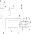
- FIGS. 3A And 3B represent a second example of a microscopic analysis system 200 according to the present disclosure, configured for ex vivo microscopic analysis of a sample and in vivo microscopic analysis of skin.
- the FIG. 3A represents the microscopic analysis system in a first operating mode of in vivo microscopic analysis of the skin and the FIG. 3B represents the microscopic analysis system in a second operating mode of ex vivo microscopic analysis of a sample.
- FIGS 3A And 3B similar to those of FIGS 2A And 2B are referenced identically and are not described again.
- the distal portion 221 of the mount 220 comprises a transmission window formed by a single opening 322.
- the first tip 230 comprises a transmission window formed by a single opening 331.
- the microscope objective and the skin are immersed in air.
- the distal portion 221 makes it possible in this example to protect the microscope objective 210, in particular when changing from the first operating mode of in vivo microscopic analysis to the second operating mode of ex vivo microscopic analysis, a change during which an operator removes the first tip to position the second tip (250, FIG. 3B ).
- the distal portion 221 may integrate a lighting device, as previously described by means of the FIGS 2A - 2C .
- the sample holder 260 may also not be closed by a transparent slide.
- FIG. 4 represents diagrams illustrating steps of a method for in vivo microscopic analysis of skin and ex vivo of a sample, using an analysis system according to the present description.
- the microscopic analysis method comprises fixing 41 the first tip 230 on the mount 220 and an in vivo microscopic analysis of the skin, then removing 42 the first tip 230 and fixing (steps 43, 44) the second tip 250 on the mount 220.
- the device with the second tip 250 can then be mounted on the support (270, FIG. 2B ) in order to carry out ex vivo microscopic analysis of a sample.
- the device can then be used again for in vivo microscopic analysis of the skin by removing the second tip and replacing it with a first tip.
- the first tip may be a consumable that will be changed for each new in vivo use.
- FIG. 4 illustrates how, by means of the device according to the present description, a self-alignment of the optical axis of the microscope objective can be achieved when switching from the first operating mode of in vivo microscopic analysis to the second operating mode of ex vivo microscopic analysis.
- FIG. 4 also shows an advantage of the presence of the first tip 230 fixed on the distal part 221 of the mount. Indeed, thanks to the presence of the distal part, when removing the first tip to fix the second tip 250, the microscope objective 210 is protected.
- the seal is ensured by the distal part 221 of the frame closed by the transparent window 222 and which remains in place when the first tip 230 is removed to put in place the second tip 250.
- the first tip 230 is used as a “plug” which only needs to be filled with the second immersion medium 242, liquid or gel.
- the first tip can be sealed to the distal portion of the mount.
- a third immersion liquid (not shown in the FIG. 4 ) can be arranged between the sample holder and the transparent slide 222.
- a third immersion medium whose physical characteristics, for example refractive index and/or dispersion, are substantially identical to the medium of the overlayer, and to adapt the thickness of the third immersion medium to the thickness of the overlayer to limit the variation of the optical path when changing from one operating mode to another.
Landscapes
- Physics & Mathematics (AREA)
- Chemical & Material Sciences (AREA)
- Analytical Chemistry (AREA)
- General Physics & Mathematics (AREA)
- Optics & Photonics (AREA)
- Oil, Petroleum & Natural Gas (AREA)
- Health & Medical Sciences (AREA)
- General Health & Medical Sciences (AREA)
- Surgery (AREA)
- Investigating Or Analysing Materials By Optical Means (AREA)
- Measurement Of The Respiration, Hearing Ability, Form, And Blood Characteristics Of Living Organisms (AREA)
- Investigating Or Analysing Biological Materials (AREA)
Claims (16)
- Vorrichtung (201, 301), die konfiguriert ist, um in einem ersten Funktionsmodus, der eine in vivo mikroskopische Analyse der Haut aufweist, und in einem zweiten Funktionsmodus, der eine ex vivo mikroskopische Analyse einer Probe aufweist, zu funktionieren, wobei die Vorrichtung aufweist:- ein Mikroskopobjektiv (210), das eine optische Achse (D) aufweist;- eine Halterung (220), die ein distales Teil (221, in dem das Mikroskopobjektiv angeordnet ist, und ein proximales Teil (224, das mit dem distalen Teil fest verbunden ist, aufweist, wobei das distale Teil (221) an einem Ende ein erstes Transmissionsfenster aufweist;- ein erstes Endstück (230), das an einem Ende ein zweites Transmissionsfenster aufweist und konfiguriert ist, um in dem ersten Funktionsmodus abnehmbar an dem distalen Teil (221) der Halterung (220) befestigt zu werden;- ein zweites Endstück (250), das konfiguriert ist, um in dem zweiten Funktionsmodus abnehmbar an dem distalen Teil (221) der Halterung (220) befestigt zu werden;- einen Probenhalter (260), der eine Aufnahmefläche (263) aufweist, die konfiguriert ist, um in dem zweiten Funktionsmodus eine Probe aufzunehmen;- einen Träger (270), der konfiguriert ist, um mit dem zweiten Endstück (250) in dem zweiten Funktionsmodus zusammenzuwirken, um die Halterung (220) so aufzunehmen, dass die optische Achse des Mikroskopobjektivs im Wesentlichen in einer vorbestimmten Richtung in Bezug auf die Aufnahmefläche ausgerichtet ist.
- Vorrichtung nach Anspruch 1, wobei das erste Transmissionsfenster eine erste transparente Lamelle (222) aufweist, die das Ende des distalen Teils (221) der Halterung verschließt.
- Vorrichtung nach Anspruch 2, die ferner ein erstes Immersionsmedium (241) aufweist, das mit der ersten transparenten Lamelle und dem Mikroskopobjektiv (210) in Kontakt steht.
- Vorrichtung nach einem der vorhergehenden Ansprüche, wobei das zweite Transmissionsfenster eine zweite transparente Lamelle (231) aufweist, die das Ende des ersten Endstücks (230) verschließt.
- Vorrichtung nach Anspruch 4, wobei- das erste Transmissionsfenster eine erste transparente Lamelle (222) aufweist, die das Ende des distalen Teils (221) der Halterung verschließt; und- die Vorrichtung ferner ein zweites Immersionsmedium (242) aufweist, das mit der ersten transparenten Lamelle (222) und der zweiten transparenten Lamelle (231) in Kontakt steht.
- Vorrichtung nach einem der vorhergehenden Ansprüche, wobei der Probenhalter eine dritte transparente Lamelle (262) aufweist, die den Probenhalter verschließt.
- Vorrichtung nach Anspruch 6, wobei- das erste Transmissionsfenster eine erste transparente Lamelle (222) aufweist, die den distalen Teil (221) der Halterung verschließt; und- die Vorrichtung ferner ein drittes Immersionsmedium (243) aufweist, das mit der ersten transparenten Lamelle (222) und der dritten transparenten Lamelle (262) in Kontakt steht.
- Vorrichtung nach einem der vorhergehenden Ansprüche, ferner aufweisend eine konfigurierte Beleuchtungsvorrichtung (228) für die Probe, die an einem Ende des distalen Teils (221) der Halterung angeordnet ist.
- Vorrichtung nach einem der vorhergehenden Ansprüche, wobei die Halterung (220) konfiguriert ist, um im ersten Funktionsmodus in der Hand gehalten zu werden.
- Vorrichtung nach einem der vorhergehenden Ansprüche, ferner aufweisend eine Einrichtung zum axialen Verschieben des Mikroskopobjektivs (210) im distalen Teil (221) der Halterung entlang der optischen Achse (D).
- Vorrichtung nach einem der vorhergehenden Ansprüche, welche ferner Mittel (275) zur axialen Einstellung des Trägers (270) in einer Richtung parallel zur optischen Achse (D) aufweist und/oder Mittel zur seitlichen Einstellung des Trägers in einer Ebene, die im Wesentlichen senkrecht zur optischen Achse verläuft und/oder Mittel (265) zur seitlichen Einstellung des Probenhalters in einer Ebene, die im Wesentlichen senkrecht zur optischen Achse verläuft und/oder Mittel zur axialen Einstellung des Probenhalters in einer Richtung parallel zur optischen Achse aufweist.
- Vorrichtung nach einem der vorhergehenden Ansprüche, wobei das zweite Endstück (250) eine Außenfläche aufweist, die konfiguriert ist, um mit einer Oberfläche des Trägers (270) zusammenzuwirken, um die Ausrichtung zu ermöglichen.
- Mikroskopieanalysesystem (200), das konfiguriert ist, um in einem ersten Funktionsmodus, der eine in vivo mikroskopische Analyse der Haut aufweist, und in einem zweiten Funktionsmodus, der eine ex vivo mikroskopische Analyse einer Probe aufweist, zu funktionieren, wobei das System aufweist:- eine Vorrichtung nach einem der Ansprüche 1 bis 12;- eine Beleuchtungsstrecke, die konfiguriert ist, um die Probe oder die Haut zu beleuchten;- eine Detektionsstrecke, die das Mikroskopobjektiv aufweist, wobei die Detektionsstrecke konfiguriert ist, um einen von der beleuchteten Probe oder Haut emittierten Lichtstrahl zu erfassen und ein Detektionssignal zu erzeugen;- eine Verarbeitungseinheit (290), die konfiguriert ist, um mikroskopische Analyseinformationen der Probe oder der Haut aus dem Detektionssignal zu erzeugen; und wobei- alle oder einige der Elemente der Beleuchtungsstrecke und der Detektionsstrecke in der Vorrichtung aufweisen.
- Analysesystem nach Anspruch 13, konfiguriert für konfokale Bildgebung und/oder optische Kohärenztomographie-Bildgebung, wobei die mikroskopische Analyseinformation mindestens ein Bild der Probe oder der Haut aufweist, und/oder konfiguriert für spektroskopische Analyse, wobei die mikroskopische Analyseinformation mindestens ein Spektrum des Lichtstrahls aufweist, der von der Probe oder der Haut an mindestens einem Punkt der Probe oder der Haut emittiert wird.
- Verfahren zur ex vivo mikroskopischen Analyse einer Probe und zur in vivo mikroskopischen Analyse der Haut mittels eines Analysesystems nach Anspruch 13, aufweisend:- Entfernen des zweiten Endstücks (250), Befestigen des ersten Endstücks (230) an der Halterung (220) und mikroskopische in vivo Analyse der Haut ;- Entfernen des ersten Endstücks (230), Befestigen des zweiten Endstücks (250) an der Halterung (220) und mikroskopische Ex vivo Analyse einer Probe.
- Verfahren zur Analyse einer Probe nach Anspruch 15, wobei die mikroskopische Analyse der Probe oder der Haut eine konfokale und/oder tomographische Abbildung der Probe oder der Haut mittels optischer Kohärenz aufweist und/oder eine spektroskopische Analyse der Probe oder der Haut aufweist.
Applications Claiming Priority (2)
| Application Number | Priority Date | Filing Date | Title |
|---|---|---|---|
| FR2100899A FR3119466B1 (fr) | 2021-01-29 | 2021-01-29 | Dispositifs pour l’analyse microscopique ex vivo d’échantillons et in vivo de la peau |
| PCT/EP2022/051027 WO2022161816A1 (fr) | 2021-01-29 | 2022-01-18 | Dispositifs pour l'analyse microscopique ex vivo d'echantillons et in vivo de la peau |
Publications (3)
| Publication Number | Publication Date |
|---|---|
| EP4285174A1 EP4285174A1 (de) | 2023-12-06 |
| EP4285174B1 true EP4285174B1 (de) | 2025-02-12 |
| EP4285174C0 EP4285174C0 (de) | 2025-02-12 |
Family
ID=75439002
Family Applications (1)
| Application Number | Title | Priority Date | Filing Date |
|---|---|---|---|
| EP22701922.1A Active EP4285174B1 (de) | 2021-01-29 | 2022-01-18 | Vorrichtungen zur ex-vivo mikroskopischen untersuchung von proben und zur in-vivo mikroskopischen untersuchung der haut |
Country Status (7)
| Country | Link |
|---|---|
| US (1) | US11906720B1 (de) |
| EP (1) | EP4285174B1 (de) |
| CN (1) | CN116783535B (de) |
| AU (1) | AU2022214125B2 (de) |
| ES (1) | ES3020063T3 (de) |
| FR (1) | FR3119466B1 (de) |
| WO (1) | WO2022161816A1 (de) |
Family Cites Families (11)
| Publication number | Priority date | Publication date | Assignee | Title |
|---|---|---|---|---|
| US3202049A (en) * | 1961-11-29 | 1965-08-24 | Bausch & Lomb | Liquid dispenser for microscope objective |
| US5719700A (en) * | 1991-10-11 | 1998-02-17 | L'oreal | Apparatus for in vivo observation of the microscopic structure of the skin or of a similar tissue |
| US8553322B2 (en) * | 2008-11-04 | 2013-10-08 | Dcg Systems, Inc. | Variable magnification optics with spray cooling |
| DE102013112600A1 (de) * | 2013-11-15 | 2015-05-21 | Carl Zeiss Microscopy Gmbh | Optisches Übertragungssystem und Mikroskop mit einem solchen Übertragungssystem |
| FR3015659B1 (fr) | 2013-12-20 | 2016-01-29 | Centre Nat Rech Scient | Appareil et procede de tomographie optique |
| WO2016017049A1 (ja) * | 2014-07-30 | 2016-02-04 | パナソニックIpマネジメント株式会社 | 保護部材 |
| FR3028962B1 (fr) * | 2014-11-26 | 2018-02-02 | Universite Paris-Sud | Dispositif pour objectif de microscope, et procede d'utilisation d'un tel dispositif. |
| US10514532B1 (en) | 2015-09-27 | 2019-12-24 | Caliber Imaging & Diagnostics, Inc. | Confocal microscope having a positionable imaging head mounted on a boom stand |
| JP2018146810A (ja) * | 2017-03-07 | 2018-09-20 | オリンパス株式会社 | 光学系、浸液保持器、観察装置 |
| CN111051954A (zh) * | 2017-07-20 | 2020-04-21 | 维微恩提斯显微镜有限责任公司 | 显微镜、操作显微镜的方法和对样本进行成像的方法 |
| WO2019138062A1 (en) | 2018-01-12 | 2019-07-18 | Damae Medical | Dynamic focusing system for an optical device |
-
2021
- 2021-01-29 FR FR2100899A patent/FR3119466B1/fr active Active
-
2022
- 2022-01-18 US US18/263,255 patent/US11906720B1/en active Active
- 2022-01-18 ES ES22701922T patent/ES3020063T3/es active Active
- 2022-01-18 EP EP22701922.1A patent/EP4285174B1/de active Active
- 2022-01-18 CN CN202280012606.XA patent/CN116783535B/zh active Active
- 2022-01-18 AU AU2022214125A patent/AU2022214125B2/en active Active
- 2022-01-18 WO PCT/EP2022/051027 patent/WO2022161816A1/fr not_active Ceased
Also Published As
| Publication number | Publication date |
|---|---|
| FR3119466A1 (fr) | 2022-08-05 |
| EP4285174A1 (de) | 2023-12-06 |
| EP4285174C0 (de) | 2025-02-12 |
| CN116783535A (zh) | 2023-09-19 |
| WO2022161816A1 (fr) | 2022-08-04 |
| AU2022214125B2 (en) | 2024-03-28 |
| CN116783535B (zh) | 2024-08-23 |
| AU2022214125A9 (en) | 2024-05-16 |
| ES3020063T3 (en) | 2025-05-21 |
| FR3119466B1 (fr) | 2023-02-10 |
| US20240036299A1 (en) | 2024-02-01 |
| US11906720B1 (en) | 2024-02-20 |
| AU2022214125A1 (en) | 2023-08-17 |
Similar Documents
| Publication | Publication Date | Title |
|---|---|---|
| EP3084345B1 (de) | Optische tomographievorrichtung und verfahren | |
| EP4185914B1 (de) | Systeme und verfahren zur durchführung einer mikroskopischen analyse einer probe | |
| CA2650856C (fr) | Tete optique miniaturisee a haute resolution spatiale et haute sensibilite, notamment pour l'imagerie de fluorescence confocale fibree | |
| EP2734884B1 (de) | Konoskopische optische beleuchtungsvorrichtung mit einem hohlen konus für ein optisches mikroskop und verfahren zur optischen mikroskopie in der konoskopie | |
| EP1468321B1 (de) | Miniaturisierter fokussierender optischer kopf insbesondere für ein endoskop | |
| EP3039475B1 (de) | Mikroskopiesystem und -verfahren mt kantenbeleuchtung | |
| EP3241014B1 (de) | System zur analyse einer transparenten probe mit positionssteuerung und zugehöriges verfahren | |
| FR2962531A1 (fr) | Methode et dispositif d'imagerie tridimensionnelle par microscopie interferentielle plein champ | |
| EP3614904A1 (de) | System und verfahren zur multiskaligen netzhautbildgebung | |
| EP3054281B1 (de) | Vorrichtung zum messen eines von einer probe rückgestreuten optischen signals | |
| WO2022122981A1 (fr) | Microscope confocal avec réallocation de photons | |
| EP0426571A1 (de) | Verfahren zur pünktlichen spektroskopischen Analyse von durch eine in einem Nahfeld liegende Substanz gebeugtem oder absorbiertem Licht | |
| EP4070144B1 (de) | Vorrichtungen und verfahren für rastermikroskopie | |
| FR3058792A1 (fr) | Dispositif de distribution et de collecte de lumiere pour mesurer la dispersion raman d'un echantillon | |
| EP4285174A1 (de) | Vorrichtungen zur ex-vivo mikroskopischen untersuchung von proben und zur in-vivo mikroskopischen untersuchung der haut | |
| WO2017005909A1 (fr) | Dispositif de spectroscopie, notamment spectroscopie raman, et procede associe | |
| WO2025114561A1 (fr) | Dispositif de guidage pour le guidage axial d'une sonde d'imagerie fibrée | |
| FR3149381A3 (fr) | Microscope-sonde raman miniature | |
| FR2726917A1 (fr) | Plate-forme universelle pour microscope | |
| EP2888990A1 (de) | Vorrichtung zur Entnahme eines biologischen Gewebes | |
| WO2010066969A1 (fr) | Dispositif et procede d'imagerie par detection non-lineaire |
Legal Events
| Date | Code | Title | Description |
|---|---|---|---|
| STAA | Information on the status of an ep patent application or granted ep patent |
Free format text: STATUS: UNKNOWN |
|
| STAA | Information on the status of an ep patent application or granted ep patent |
Free format text: STATUS: THE INTERNATIONAL PUBLICATION HAS BEEN MADE |
|
| PUAI | Public reference made under article 153(3) epc to a published international application that has entered the european phase |
Free format text: ORIGINAL CODE: 0009012 |
|
| STAA | Information on the status of an ep patent application or granted ep patent |
Free format text: STATUS: REQUEST FOR EXAMINATION WAS MADE |
|
| 17P | Request for examination filed |
Effective date: 20230728 |
|
| AK | Designated contracting states |
Kind code of ref document: A1 Designated state(s): AL AT BE BG CH CY CZ DE DK EE ES FI FR GB GR HR HU IE IS IT LI LT LU LV MC MK MT NL NO PL PT RO RS SE SI SK SM TR |
|
| DAV | Request for validation of the european patent (deleted) | ||
| DAX | Request for extension of the european patent (deleted) | ||
| GRAP | Despatch of communication of intention to grant a patent |
Free format text: ORIGINAL CODE: EPIDOSNIGR1 |
|
| STAA | Information on the status of an ep patent application or granted ep patent |
Free format text: STATUS: GRANT OF PATENT IS INTENDED |
|
| INTG | Intention to grant announced |
Effective date: 20240913 |
|
| GRAS | Grant fee paid |
Free format text: ORIGINAL CODE: EPIDOSNIGR3 |
|
| GRAA | (expected) grant |
Free format text: ORIGINAL CODE: 0009210 |
|
| STAA | Information on the status of an ep patent application or granted ep patent |
Free format text: STATUS: THE PATENT HAS BEEN GRANTED |
|
| AK | Designated contracting states |
Kind code of ref document: B1 Designated state(s): AL AT BE BG CH CY CZ DE DK EE ES FI FR GB GR HR HU IE IS IT LI LT LU LV MC MK MT NL NO PL PT RO RS SE SI SK SM TR |
|
| REG | Reference to a national code |
Ref country code: GB Ref legal event code: FG4D Free format text: NOT ENGLISH |
|
| REG | Reference to a national code |
Ref country code: CH Ref legal event code: EP |
|
| REG | Reference to a national code |
Ref country code: DE Ref legal event code: R096 Ref document number: 602022010497 Country of ref document: DE |
|
| REG | Reference to a national code |
Ref country code: IE Ref legal event code: FG4D Free format text: LANGUAGE OF EP DOCUMENT: FRENCH |
|
| U01 | Request for unitary effect filed |
Effective date: 20250228 |
|
| U07 | Unitary effect registered |
Designated state(s): AT BE BG DE DK EE FI FR IT LT LU LV MT NL PT RO SE SI Effective date: 20250310 |
|
| REG | Reference to a national code |
Ref country code: ES Ref legal event code: FG2A Ref document number: 3020063 Country of ref document: ES Kind code of ref document: T3 Effective date: 20250521 |
|
| PG25 | Lapsed in a contracting state [announced via postgrant information from national office to epo] |
Ref country code: RS Free format text: LAPSE BECAUSE OF FAILURE TO SUBMIT A TRANSLATION OF THE DESCRIPTION OR TO PAY THE FEE WITHIN THE PRESCRIBED TIME-LIMIT Effective date: 20250512 |
|
| PG25 | Lapsed in a contracting state [announced via postgrant information from national office to epo] |
Ref country code: PL Free format text: LAPSE BECAUSE OF FAILURE TO SUBMIT A TRANSLATION OF THE DESCRIPTION OR TO PAY THE FEE WITHIN THE PRESCRIBED TIME-LIMIT Effective date: 20250212 |
|
| PG25 | Lapsed in a contracting state [announced via postgrant information from national office to epo] |
Ref country code: IS Free format text: LAPSE BECAUSE OF FAILURE TO SUBMIT A TRANSLATION OF THE DESCRIPTION OR TO PAY THE FEE WITHIN THE PRESCRIBED TIME-LIMIT Effective date: 20250612 Ref country code: NO Free format text: LAPSE BECAUSE OF FAILURE TO SUBMIT A TRANSLATION OF THE DESCRIPTION OR TO PAY THE FEE WITHIN THE PRESCRIBED TIME-LIMIT Effective date: 20250512 |
|
| PG25 | Lapsed in a contracting state [announced via postgrant information from national office to epo] |
Ref country code: HR Free format text: LAPSE BECAUSE OF FAILURE TO SUBMIT A TRANSLATION OF THE DESCRIPTION OR TO PAY THE FEE WITHIN THE PRESCRIBED TIME-LIMIT Effective date: 20250212 |
|
| PG25 | Lapsed in a contracting state [announced via postgrant information from national office to epo] |
Ref country code: GR Free format text: LAPSE BECAUSE OF FAILURE TO SUBMIT A TRANSLATION OF THE DESCRIPTION OR TO PAY THE FEE WITHIN THE PRESCRIBED TIME-LIMIT Effective date: 20250513 |
|
| PG25 | Lapsed in a contracting state [announced via postgrant information from national office to epo] |
Ref country code: SM Free format text: LAPSE BECAUSE OF FAILURE TO SUBMIT A TRANSLATION OF THE DESCRIPTION OR TO PAY THE FEE WITHIN THE PRESCRIBED TIME-LIMIT Effective date: 20250212 |
|
| PG25 | Lapsed in a contracting state [announced via postgrant information from national office to epo] |
Ref country code: CZ Free format text: LAPSE BECAUSE OF FAILURE TO SUBMIT A TRANSLATION OF THE DESCRIPTION OR TO PAY THE FEE WITHIN THE PRESCRIBED TIME-LIMIT Effective date: 20250212 |
|
| PG25 | Lapsed in a contracting state [announced via postgrant information from national office to epo] |
Ref country code: SK Free format text: LAPSE BECAUSE OF FAILURE TO SUBMIT A TRANSLATION OF THE DESCRIPTION OR TO PAY THE FEE WITHIN THE PRESCRIBED TIME-LIMIT Effective date: 20250212 |
|
| PLBE | No opposition filed within time limit |
Free format text: ORIGINAL CODE: 0009261 |
|
| STAA | Information on the status of an ep patent application or granted ep patent |
Free format text: STATUS: NO OPPOSITION FILED WITHIN TIME LIMIT |
|
| REG | Reference to a national code |
Ref country code: CH Ref legal event code: L10 Free format text: ST27 STATUS EVENT CODE: U-0-0-L10-L00 (AS PROVIDED BY THE NATIONAL OFFICE) Effective date: 20251224 |
|
| 26N | No opposition filed |
Effective date: 20251113 |
|
| REG | Reference to a national code |
Ref country code: CH Ref legal event code: U11 Free format text: ST27 STATUS EVENT CODE: U-0-0-U10-U11 (AS PROVIDED BY THE NATIONAL OFFICE) Effective date: 20260201 |
|
| U20 | Renewal fee for the european patent with unitary effect paid |
Year of fee payment: 5 Effective date: 20251231 |
|
| PGFP | Annual fee paid to national office [announced via postgrant information from national office to epo] |
Ref country code: GB Payment date: 20260127 Year of fee payment: 5 |
|
| PGFP | Annual fee paid to national office [announced via postgrant information from national office to epo] |
Ref country code: ES Payment date: 20260209 Year of fee payment: 5 |
|
| PGFP | Annual fee paid to national office [announced via postgrant information from national office to epo] |
Ref country code: CH Payment date: 20260201 Year of fee payment: 5 |