EP4285036B1 - Boîtier d'actionneur électromécanique de frein à disque comportant un element amortisseur - Google Patents
Boîtier d'actionneur électromécanique de frein à disque comportant un element amortisseur Download PDFInfo
- Publication number
- EP4285036B1 EP4285036B1 EP22704935.0A EP22704935A EP4285036B1 EP 4285036 B1 EP4285036 B1 EP 4285036B1 EP 22704935 A EP22704935 A EP 22704935A EP 4285036 B1 EP4285036 B1 EP 4285036B1
- Authority
- EP
- European Patent Office
- Prior art keywords
- housing
- cover
- case
- damping element
- damping
- Prior art date
- Legal status (The legal status is an assumption and is not a legal conclusion. Google has not performed a legal analysis and makes no representation as to the accuracy of the status listed.)
- Active
Links
Images
Classifications
-
- F—MECHANICAL ENGINEERING; LIGHTING; HEATING; WEAPONS; BLASTING
- F16—ENGINEERING ELEMENTS AND UNITS; GENERAL MEASURES FOR PRODUCING AND MAINTAINING EFFECTIVE FUNCTIONING OF MACHINES OR INSTALLATIONS; THERMAL INSULATION IN GENERAL
- F16D—COUPLINGS FOR TRANSMITTING ROTATION; CLUTCHES; BRAKES
- F16D55/00—Brakes with substantially-radial braking surfaces pressed together in axial direction, e.g. disc brakes
- F16D55/02—Brakes with substantially-radial braking surfaces pressed together in axial direction, e.g. disc brakes with axially-movable discs or pads pressed against axially-located rotating members
- F16D55/22—Brakes with substantially-radial braking surfaces pressed together in axial direction, e.g. disc brakes with axially-movable discs or pads pressed against axially-located rotating members by clamping an axially-located rotating disc between movable braking members, e.g. movable brake discs or brake pads
- F16D55/224—Brakes with substantially-radial braking surfaces pressed together in axial direction, e.g. disc brakes with axially-movable discs or pads pressed against axially-located rotating members by clamping an axially-located rotating disc between movable braking members, e.g. movable brake discs or brake pads with a common actuating member for the braking members
- F16D55/225—Brakes with substantially-radial braking surfaces pressed together in axial direction, e.g. disc brakes with axially-movable discs or pads pressed against axially-located rotating members by clamping an axially-located rotating disc between movable braking members, e.g. movable brake discs or brake pads with a common actuating member for the braking members the braking members being brake pads
-
- F—MECHANICAL ENGINEERING; LIGHTING; HEATING; WEAPONS; BLASTING
- F16—ENGINEERING ELEMENTS AND UNITS; GENERAL MEASURES FOR PRODUCING AND MAINTAINING EFFECTIVE FUNCTIONING OF MACHINES OR INSTALLATIONS; THERMAL INSULATION IN GENERAL
- F16H—GEARING
- F16H57/00—General details of gearing
- F16H57/02—Gearboxes; Mounting gearing therein
- F16H57/028—Gearboxes; Mounting gearing therein characterised by means for reducing vibration or noise
-
- F—MECHANICAL ENGINEERING; LIGHTING; HEATING; WEAPONS; BLASTING
- F16—ENGINEERING ELEMENTS AND UNITS; GENERAL MEASURES FOR PRODUCING AND MAINTAINING EFFECTIVE FUNCTIONING OF MACHINES OR INSTALLATIONS; THERMAL INSULATION IN GENERAL
- F16D—COUPLINGS FOR TRANSMITTING ROTATION; CLUTCHES; BRAKES
- F16D55/00—Brakes with substantially-radial braking surfaces pressed together in axial direction, e.g. disc brakes
- F16D55/02—Brakes with substantially-radial braking surfaces pressed together in axial direction, e.g. disc brakes with axially-movable discs or pads pressed against axially-located rotating members
- F16D55/22—Brakes with substantially-radial braking surfaces pressed together in axial direction, e.g. disc brakes with axially-movable discs or pads pressed against axially-located rotating members by clamping an axially-located rotating disc between movable braking members, e.g. movable brake discs or brake pads
- F16D55/224—Brakes with substantially-radial braking surfaces pressed together in axial direction, e.g. disc brakes with axially-movable discs or pads pressed against axially-located rotating members by clamping an axially-located rotating disc between movable braking members, e.g. movable brake discs or brake pads with a common actuating member for the braking members
- F16D55/225—Brakes with substantially-radial braking surfaces pressed together in axial direction, e.g. disc brakes with axially-movable discs or pads pressed against axially-located rotating members by clamping an axially-located rotating disc between movable braking members, e.g. movable brake discs or brake pads with a common actuating member for the braking members the braking members being brake pads
- F16D55/226—Brakes with substantially-radial braking surfaces pressed together in axial direction, e.g. disc brakes with axially-movable discs or pads pressed against axially-located rotating members by clamping an axially-located rotating disc between movable braking members, e.g. movable brake discs or brake pads with a common actuating member for the braking members the braking members being brake pads in which the common actuating member is moved axially, e.g. floating caliper disc brakes
-
- F—MECHANICAL ENGINEERING; LIGHTING; HEATING; WEAPONS; BLASTING
- F16—ENGINEERING ELEMENTS AND UNITS; GENERAL MEASURES FOR PRODUCING AND MAINTAINING EFFECTIVE FUNCTIONING OF MACHINES OR INSTALLATIONS; THERMAL INSULATION IN GENERAL
- F16D—COUPLINGS FOR TRANSMITTING ROTATION; CLUTCHES; BRAKES
- F16D65/00—Parts or details
- F16D65/02—Braking members; Mounting thereof
- F16D65/04—Bands, shoes or pads; Pivots or supporting members therefor
- F16D65/092—Bands, shoes or pads; Pivots or supporting members therefor for axially-engaging brakes, e.g. disc brakes
- F16D65/095—Pivots or supporting members therefor
- F16D65/097—Resilient means interposed between pads and supporting members or other brake parts
- F16D65/0973—Resilient means interposed between pads and supporting members or other brake parts not subjected to brake forces
- F16D65/0979—Resilient means interposed between pads and supporting members or other brake parts not subjected to brake forces acting on the rear side of the pad or an element affixed thereto, e.g. spring clips securing the pad to the brake piston or caliper
-
- F—MECHANICAL ENGINEERING; LIGHTING; HEATING; WEAPONS; BLASTING
- F16—ENGINEERING ELEMENTS AND UNITS; GENERAL MEASURES FOR PRODUCING AND MAINTAINING EFFECTIVE FUNCTIONING OF MACHINES OR INSTALLATIONS; THERMAL INSULATION IN GENERAL
- F16D—COUPLINGS FOR TRANSMITTING ROTATION; CLUTCHES; BRAKES
- F16D65/00—Parts or details
- F16D65/14—Actuating mechanisms for brakes; Means for initiating operation at a predetermined position
- F16D65/16—Actuating mechanisms for brakes; Means for initiating operation at a predetermined position arranged in or on the brake
- F16D65/18—Actuating mechanisms for brakes; Means for initiating operation at a predetermined position arranged in or on the brake adapted for drawing members together, e.g. for disc brakes
-
- F—MECHANICAL ENGINEERING; LIGHTING; HEATING; WEAPONS; BLASTING
- F16—ENGINEERING ELEMENTS AND UNITS; GENERAL MEASURES FOR PRODUCING AND MAINTAINING EFFECTIVE FUNCTIONING OF MACHINES OR INSTALLATIONS; THERMAL INSULATION IN GENERAL
- F16D—COUPLINGS FOR TRANSMITTING ROTATION; CLUTCHES; BRAKES
- F16D65/00—Parts or details
- F16D65/14—Actuating mechanisms for brakes; Means for initiating operation at a predetermined position
- F16D65/16—Actuating mechanisms for brakes; Means for initiating operation at a predetermined position arranged in or on the brake
- F16D65/18—Actuating mechanisms for brakes; Means for initiating operation at a predetermined position arranged in or on the brake adapted for drawing members together, e.g. for disc brakes
- F16D65/183—Actuating mechanisms for brakes; Means for initiating operation at a predetermined position arranged in or on the brake adapted for drawing members together, e.g. for disc brakes with force-transmitting members arranged side by side acting on a spot type force-applying member
-
- F—MECHANICAL ENGINEERING; LIGHTING; HEATING; WEAPONS; BLASTING
- F16—ENGINEERING ELEMENTS AND UNITS; GENERAL MEASURES FOR PRODUCING AND MAINTAINING EFFECTIVE FUNCTIONING OF MACHINES OR INSTALLATIONS; THERMAL INSULATION IN GENERAL
- F16F—SPRINGS; SHOCK-ABSORBERS; MEANS FOR DAMPING VIBRATION
- F16F1/00—Springs
- F16F1/36—Springs made of rubber or other material having high internal friction, e.g. thermoplastic elastomers
- F16F1/373—Springs made of rubber or other material having high internal friction, e.g. thermoplastic elastomers characterised by having a particular shape
- F16F1/3732—Springs made of rubber or other material having high internal friction, e.g. thermoplastic elastomers characterised by having a particular shape having an annular or the like shape, e.g. grommet-type resilient mountings
-
- F—MECHANICAL ENGINEERING; LIGHTING; HEATING; WEAPONS; BLASTING
- F16—ENGINEERING ELEMENTS AND UNITS; GENERAL MEASURES FOR PRODUCING AND MAINTAINING EFFECTIVE FUNCTIONING OF MACHINES OR INSTALLATIONS; THERMAL INSULATION IN GENERAL
- F16H—GEARING
- F16H57/00—General details of gearing
- F16H57/02—Gearboxes; Mounting gearing therein
- F16H57/031—Gearboxes; Mounting gearing therein characterised by covers or lids for gearboxes
-
- H—ELECTRICITY
- H02—GENERATION; CONVERSION OR DISTRIBUTION OF ELECTRIC POWER
- H02K—DYNAMO-ELECTRIC MACHINES
- H02K5/00—Casings; Enclosures; Supports
- H02K5/24—Casings; Enclosures; Supports specially adapted for suppression or reduction of noise or vibrations
-
- H—ELECTRICITY
- H02—GENERATION; CONVERSION OR DISTRIBUTION OF ELECTRIC POWER
- H02K—DYNAMO-ELECTRIC MACHINES
- H02K7/00—Arrangements for handling mechanical energy structurally associated with dynamo-electric machines, e.g. structural association with mechanical driving motors or auxiliary dynamo-electric machines
- H02K7/10—Structural association with clutches, brakes, gears, pulleys or mechanical starters
- H02K7/116—Structural association with clutches, brakes, gears, pulleys or mechanical starters with gears
-
- F—MECHANICAL ENGINEERING; LIGHTING; HEATING; WEAPONS; BLASTING
- F16—ENGINEERING ELEMENTS AND UNITS; GENERAL MEASURES FOR PRODUCING AND MAINTAINING EFFECTIVE FUNCTIONING OF MACHINES OR INSTALLATIONS; THERMAL INSULATION IN GENERAL
- F16D—COUPLINGS FOR TRANSMITTING ROTATION; CLUTCHES; BRAKES
- F16D2121/00—Type of actuator operation force
- F16D2121/18—Electric or magnetic
- F16D2121/24—Electric or magnetic using motors
-
- F—MECHANICAL ENGINEERING; LIGHTING; HEATING; WEAPONS; BLASTING
- F16—ENGINEERING ELEMENTS AND UNITS; GENERAL MEASURES FOR PRODUCING AND MAINTAINING EFFECTIVE FUNCTIONING OF MACHINES OR INSTALLATIONS; THERMAL INSULATION IN GENERAL
- F16D—COUPLINGS FOR TRANSMITTING ROTATION; CLUTCHES; BRAKES
- F16D65/00—Parts or details
- F16D65/0006—Noise or vibration control
-
- F—MECHANICAL ENGINEERING; LIGHTING; HEATING; WEAPONS; BLASTING
- F16—ENGINEERING ELEMENTS AND UNITS; GENERAL MEASURES FOR PRODUCING AND MAINTAINING EFFECTIVE FUNCTIONING OF MACHINES OR INSTALLATIONS; THERMAL INSULATION IN GENERAL
- F16H—GEARING
- F16H57/00—General details of gearing
- F16H57/02—Gearboxes; Mounting gearing therein
- F16H2057/02034—Gearboxes combined or connected with electric machines
-
- F—MECHANICAL ENGINEERING; LIGHTING; HEATING; WEAPONS; BLASTING
- F16—ENGINEERING ELEMENTS AND UNITS; GENERAL MEASURES FOR PRODUCING AND MAINTAINING EFFECTIVE FUNCTIONING OF MACHINES OR INSTALLATIONS; THERMAL INSULATION IN GENERAL
- F16H—GEARING
- F16H57/00—General details of gearing
- F16H57/02—Gearboxes; Mounting gearing therein
- F16H2057/02039—Gearboxes for particular applications
- F16H2057/02082—Gearboxes for particular applications for application in vehicles other than propelling, e.g. adjustment of parts
Definitions
- the present invention relates to an electromechanical actuator housing.
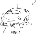
- the Figure 1 an example of a caliper body 1 of an electromechanical disc brake is shown in perspective.
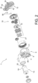
- the Figure 2 represents, according to an exploded view, an example of an electromechanical actuator 7 intended to equip such a stirrup.
- the caliper body 1 comprises a base 2 extended by an arch 4, itself extended by fingers 6.
- the base 2 comprises a housing in which a movable piston is engaged to press a brake pad, not shown, onto a brake disc.
- This base 2 also contains in the rear region of the piston a movement transformation mechanism with a helical connection, to convert a rotational movement into a translational movement of the piston, which corresponds to converting a moment of forces into a pressing force.
- This caliper body 1 is further equipped with an electromechanical actuator 7 to act on the piston so as to press the pad against the disc, upon activation of this actuator 7.
- This actuator 7 comprises a housing 8, or casing, having a fixing face 9, visible on the Figure 2 , by which it is intended to be coupled to the caliper body 1, and an opposite face 11 closed by a cover 12.
- the fixing face 9 and the opposite face 11 are substantially flat faces parallel to each other.
- the fixing face 9 comprises a main portion surrounding an opening 28 forming a centering.
- the fixing face 9 of the housing 8 is further applied against the base 2 of the caliper body 1, which is a completely flat surface.
- the housing 8 contains various components forming a motorization assembly 13 coupled to a mechanical reducer 14 which makes it possible to move the piston when this reducer 14 is coupled to the caliper body 1, that is to say when the actuator 7 is fixed to the base 2.
- the reducer 14 drives two epicyclic gear trains 18.
- the motorization assembly 13 comprises an electric motor 19 having an output pinion 20.
- the elements of the reducer 14 rotate around axes parallel to the rotation axis AM of the motor 19.
- the axis AM is parallel to a main axis AX which corresponds to the translation axis of the piston when the actuator 7 is mounted on the caliper body 1, this axis AX extending transversely relative to the vehicle equipped with the brake.
- the epicyclic gear train 18 comprises a coupling element 27, for example of the torx TM type, which opens into a corresponding opening 28 of the fixing face 9, to drive the movement transformation mechanism housed in the base 2.
- the caliper also comprises, in addition to the electromechanical means for moving the piston, hydraulic means for moving the piston.
- the electromechanical means ensure the movement of the piston in the case of parking and/or emergency braking
- the hydraulic means ensure its movement in the case of service braking.
- the cover 12 which closes the opposite face 11 of the housing 8 of the electromechanical actuator 7, is fixed directly onto the housing 8 of the electromechanical actuator.
- the document KR 2019 0029002 A describes an electromechanical actuator for pressing one or more brake pads against the disc to generate braking.
- the actuator includes a housing and a cover, and a damper placed between the housing and the cover.
- the object of the invention is to provide a housing for an actuator which is designed so as to limit the overall noise produced by the electromechanical actuator.
- the invention therefore relates, according to one of its aspects, to an electromechanical actuator housing comprising an open face and on which, said open face, a cover is mounted to close an opening of said open face, the housing further comprising damping elements associated with the cover interposed between the cover and the housing, each damping element extending in a main vertical direction and comprising a lower section which is received in an associated housing of the housing and an upper section which is received in an associated housing of the cover.
- damping methods help to reduce the amplitude of the vibrations of the cover, which come from the housing. Since the vibrations of the cover are therefore less, the noise generated is also reduced.
- said damping elements are compressed between the housing and the cover.
- the housing comprises two damping elements distributed symmetrically with respect to a main median axis of the cover.
- each section of a damping element is compressed horizontally in the housing associated with it.
- each damping element is compressed in the vertical direction by the cover and the housing.
- each housing of the cover and the housing comprises a bottom against which a vertical end of the damping element bears vertically.
- the invention also relates to an electromechanical actuator for a motor vehicle disc brake caliper, which comprises a housing according to the invention.
- the invention also relates to a motor vehicle disc brake caliper, which comprises an electromechanical actuator according to the invention.
- the invention also relates to a motor vehicle disc brake, characterized in that it comprises a caliper according to the invention.
- the longitudinal, vertical, transverse orientation will also be used according to the V, L, T reference indicated in the figures, for which the vertical orientation is the orientation parallel to the AM and AX axes, the longitudinal orientation is the main direction of the cover 12 and the transverse orientation is parallel to the plane of the cover 12, according to its width.
- the housing 8 has an open face 11, on which a cover 12 is mounted.
- a rib 30 projects from the face 11, over the entire periphery thereof.
- the rib 30 is received in an associated groove 32 of the cover 12.
- the cover 12 then vibrates like a membrane, it also vibrates in torsion around its main longitudinal axis.
- the cover comprises ribs 34, forming for example a hexagonal structure called a honeycomb.
- damping elements 36 are attached to the cover 12, thus limiting its vibrations.
- the damping elements 36 are compressed between the cover 12 and the housing 8, thus producing a support on the cover 12 and damping the vibrations thereof.
- two damping elements 36 are mounted between the housing 8 and the cover 12.
- the damping elements 36 are distributed symmetrically with respect to a median vertical longitudinal plane of the cover 12.
- Each damping element 36 is made of an elastic material such as an elastomer, which provides it with viscoelastic and/or shear AV damping of at least part of the vibrations to which it is subjected.
- the damping elements 36 are arranged in locations where they do not interfere with other components of the actuator 7.
- each damping element 36 has a vertical main orientation and it comprises an upper section 38 which cooperates with the cover 12 and a lower section 40 which cooperates with the housing 8.
- the cover 12 comprises a housing 42 which is associated with each damping element and in which the upper section 38 of the associated damping element 36 is received.
- the upper section 38 of the damping element 36 is compressed horizontally by the walls of the housing 42 when it is received in this housing 42.
- the housing 8 comprises a housing 44 which is associated with each damping element 36 and in which the lower section 40 of the damping element 36 is received.
- the lower section 40 of the damping element 36 is compressed horizontally by the walls of the housing 44 of the casing 8 when it is received in this housing 44.
- each damping element 36 has a volume substantially equal to that of the corresponding housings 42, 44.
- Each damping element 36 is thus received in each housing 42, 44 with constraint on at least a portion of the surface of the walls of said corresponding housings 42, 44.
- Each damping element 36 is further compressed vertically between the housing 8 and the cover 12.
- the associated housings 42, 44 each comprise a bottom wall 50 on which an associated vertical end 46, 48 is placed in vertical support when the cover 12 is mounted on the housing 8.
- damping elements 36 makes it possible to limit the amplitude of the vibrations producing noise, without having to modify the cover 12 or the housing 8.
- the housings 42, 44 intended to receive the damping elements can be housings already present on the cover 12 and the housing 8, the shapes and dimensions of the damping elements 36 are then determined according to the shapes and dimensions of the housings 42, 44 intended to receive the damping elements 36.
- the two damping elements 36 are of similar shapes and are arranged symmetrically with respect to a median longitudinal axis of the cover 12.
- This arrangement makes it possible, in addition to damping the vibrations of the cover 12 in the manner of a membrane, to dampen the vibrations of the cover 12 in torsion around this median longitudinal axis of the cover 12.
- damping elements 36 may be arranged in the actuator 7 in other locations and/or in a non-symmetrical manner.
Landscapes
- Engineering & Computer Science (AREA)
- General Engineering & Computer Science (AREA)
- Mechanical Engineering (AREA)
- Power Engineering (AREA)
- Vibration Prevention Devices (AREA)
- Braking Arrangements (AREA)
Description
- La présente invention se rapporte à un boîtier d'actionneur électromécanique.
- En référence à la
figure 1 , on a représenté, en perspective, un exemple de corps d'étrier 1 de frein à disque électromécanique. Par ailleurs, lafigure 2 représente, selon une vue éclatée, un exemple d'actionneur électromécanique 7 destiné à équiper un tel étrier. Comme visible sur lafigure 1 , le corps d'étrier 1 comporte une base 2 prolongée par une voûte 4, elle-même prolongée par des doigts 6. La base 2 comporte un logement dans lequel est engagé un piston mobile pour presser une plaquette de frein non représentée sur un disque de freinage. Cette base 2 renferme encore dans la région arrière du piston un mécanisme de transformation de mouvement à liaison hélicoïdale, pour convertir un mouvement de rotation en un mouvement de translation du piston, ce qui correspond à convertir un moment de forces en un effort presseur. - Ce corps d'étrier 1 est en outre équipé d'un actionneur électromécanique 7 pour agir sur le piston de façon à presser la plaquette contre le disque, sur activation de cet actionneur 7. Cet actionneur 7 comprend un boîtier 8, ou carter, ayant une face de fixation 9, visible sur la
figure 2 , par laquelle il est destiné à être accouplé au corps d'étrier 1, et une face opposée 11 fermée par un couvercle 12. La face de fixation 9 et la face opposée 11 sont des faces sensiblement planes et parallèles l'une à l'autre. - De plus, comme visible sur la
figure 2 , la face de fixation 9 comporte une portion principale entourant une ouverture 28 formant un centrage. La face de fixation 9 du boîtier 8 est en outre appliquée contre la base 2 du corps d'étrier 1, qui est une surface entièrement plane. - Le boîtier 8 renferme différents composants formant un ensemble de motorisation 13 accouplé à un réducteur mécanique 14 qui permet de déplacer le piston lorsque ce réducteur 14 est accouplé au corps d'étrier 1, c'est-à-dire lorsque l'actionneur 7 est fixé à la base 2. Le réducteur 14-entraîne deux trains épicycloïdaux 18. L'ensemble de motorisation 13 comporte un moteur électrique 19 ayant un pignon de sortie 20.
- Comme visible sur la
figure 2 , les éléments du réducteur 14 tournent autour d'axes parallèles à l'axe de rotation AM du moteur 19. Dans l'exemple des figures, l'axe AM est parallèle à un axe principal AX qui correspond à l'axe de translation du piston lorsque l'actionneur 7 est monté sur le corps d'étrier 1, cet axe AX s'étendant transversalement par rapport au véhicule équipé du frein. - Lorsque l'actionneur 7 est monté, le moteur 19 est en place dans la cavité correspondant à l'ouverture 24, et le pignon 20 entraîne une roue dentée simple (non représentée). Le train épicycloïdal 18 comporte un élément d'accouplement 27, par exemple de type torx™, qui débouche dans une ouverture correspondante 28 de la face de fixation 9, pour entraîner le mécanisme de transformation de mouvement logé dans la base 2.
- Par ailleurs, l'étrier comporte aussi, outre les moyens électromécaniques de déplacement du piston, des moyens hydrauliques de déplacement du piston. Dans ce cas, les moyens électromécaniques assurent le déplacement du piston dans le cas d'un freinage de parking et/ou de secours, et les moyens hydrauliques assurent son déplacement en cas de freinage de service.
- De façon classique, le couvercle 12, qui vient fermer la face opposée 11 du boîtier 8 de l'actionneur électromécanique 7, est fixé directement sur le boîtier 8 de l'actionneur électromécanique.
- Ainsi, les vibrations qui sont produites par l'ensemble de motorisation 13 et le réducteur 14, sont transmises directement au couvercle 12. Le couvercle 12, en vibrant, produit alors un bruit relativement important.
- Le document
KR 2019 0029002 A - L'invention a pour but de proposer un boîtier d'un actionneur qui est conçu de manière à limiter le bruit global produit par l'actionneur électromécanique
- L'invention a donc pour objet, selon l'un de ses aspects, un boîtier d'actionneur électromécanique comportant une face ouverte et sur laquelle dite face ouverte, un couvercle est monté pour fermer une ouverture de ladite face ouverte, le boîtier comportant en outre des éléments amortisseurs associées au couvercle interposés entre le couvercle et le boîtier, chaque élément amortisseur s'étendant selon une direction principale verticale et comporte un tronçon inférieur qui est reçu dans un logement associé du boiter et un tronçon supérieur qui est reçu dans un logement associé du couvercle.
- Ces moyens d'amortissement permettent notamment de réduire l'amplitude des vibrations du couvercle, qui proviennent du boîtier. Les vibrations du couvercle étant par conséquent moindres, le bruit généré est par conséquent lui aussi réduit.
- De préférence, lesdits éléments amortisseurs sont comprimés entre le boîtier et le couvercle.
- De préférence, le boîtier comporte deux éléments amortisseurs répartis symétriquement par rapport à un axe principal médian du couvercle.
- De préférence, chaque tronçon d'un élément amortisseur est comprimé horizontalement dans le logement qui lui est associé.
- De préférence, chaque élément amortisseur est comprimé selon la direction verticale par le couvercle et le boîtier.
- De préférence, chaque logement du couvercle et du boîtier comporte un fond contre lequel une extrémité verticale de l'élément amortisseur est en appui verticalement. L'invention concerne aussi un actionneur électromécanique pour étrier de frein à disque de véhicule automobile, qui comporte un boîtier selon l'invention.
- L'invention concerne aussi un étrier de frein à disque de véhicule automobile, qui comporte un actionneur électromécanique selon l'invention.
- L'invention concerne aussi un frein à disque de véhicule automobile, caractérisé en ce qu'il comporte un étrier selon l'invention.
-
- [
Fig. 1 ] est une vue d'ensemble, en perspective, d'un corps d'étrier de frein électromécanique représenté seul. - [
Fig. 2 ] est une vue d'ensemble, éclatée, d'un actionneur électromécanique destiné à équiper un étrier. - [
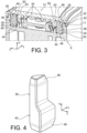
Fig. 3 ] est une vue en coupe d'un actionneur similaire à celui représenté auxfigures 1 et2 , montrant la liaison amortie entre le boîtier et le couvercle. - [
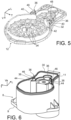
Fig. 4 ] est une représentation schématique en perspective d'un amortisseur installé entre le boîtier et le couvercle à lafigure 3 . - [
Fig. 5 ] est une représentation schématique en perspective du couvercle sur lequel deux amortisseurs sont montés. - [
Fig. 6 ] est une représentation schématique en perspective du boîtier sur lequel deux amortisseurs sont montés. - Dans la description qui va suivre, des éléments identiques, similaires ou analogues seront désignés par les mêmes chiffres de référence.
- On utilisera aussi l'orientation longitudinale, verticale, transversale selon le repère V, L, T indiqué aux figures, pour laquelle l'orientation verticale est l'orientation parallèle aux axes AM et AX, l'orientation longitudinale est la direction principale du couvercle 12 et l'orientation transversale est parallèle au plan du couvercle 12, selon sa largeur.
- Les
figures 1 et2 ont déjà été décrites précédemment dans la partie relative à l'état de la technique antérieure et au contexte technique de l'invention. Il est à noter que les caractéristiques propres au corps d'étrier 1, au boîtier 8 et à l'actionneur électromécanique 7, notamment leurs éléments constitutifs, ne sont pas décrites de nouveau ici, seules les caractéristiques propres au couvercle 12 étant explicitées. Toutefois, le boîtier 8, l'actionneur électromécanique 7 et l'étrier de frein conformes à l'invention peuvent comporter l'une quelconque de ces caractéristiques, seules ou en combinaison, décrites précédemment en référence auxfigures 1 et2 . - En référence aux
figures 3 et suivantes, on va décrire un mode de réalisation préféré de la liaison entre le boîtier 8 et le couvercle 12. - Comme on l'a dit précédemment, le boîtier 8 comporte une face 11 ouverte, sur laquelle un couvercle 12 est monté.
- Afin de garantir une bonne étanchéité et un bon positionnement du couvercle 12 par rapport à la face 11 du boîtier, une nervure 30 s'étend en saillie de la face 11, sur toute la périphérie de celle-ci.
- La nervure 30 est reçue dans une gorge 32 associée du couvercle 12.
- Comme on l'a dit précédemment, lors du fonctionnement de l'actionneur 7, des vibrations sont produites par l'ensemble de motorisation et sont transmises au couvercle 12.
- Le couvercle 12 vibre alors à la façon d'une membrane, il vibre aussi en torsion autour de son axe principal longitudinal.
- Pour limiter ces vibrations, comme on peut le voir à la
figure 5 , le couvercle comporte des nervures 34, formant par exemple une structure hexagonale dite en nid d'abeille. - Pour compléter l'effet de ces nervures, des éléments amortisseurs 36 sont joints au couvercle 12, limitant ainsi ses vibrations.
- Les éléments amortisseurs 36 sont comprimés entre le couvercle 12 et le boîtier 8, produisant ainsi un appui sur le couvercle 12 et amortissant les vibrations de celui-ci.
- Ici, selon un mode de réalisation préféré, deux éléments amortisseurs 36 sont montés entre le boîtier 8 et le couvercle 12.
- Les éléments amortisseurs 36 sont répartis symétriquement par rapport à un plan longitudinal vertical médian du couvercle 12.
- Chaque élément amortisseur 36 est réalisé en un matériau élastique tel qu'un élastomère, ce qui lui assure un amortissement AV viscoélastique et/ou par cisaillement d'au moins une partie des vibrations auxquelles il est soumis.
- Les éléments amortisseurs 36 sont disposés à des emplacements dans lesquels ils n'interfèrent pas avec les autres composants de l'actionneur 7.
- Comme on peut le voir plus en détail à la
figure 4 , chaque élément amortisseur 36 est d'orientation principale verticale et il comporte un tronçon supérieur 38 qui coopère avec le couvercle 12 et un tronçon inférieur 40 qui coopère avec le boîtier 8. - Le couvercle 12 comporte un logement 42 qui est associé à chaque élément amortisseur et dans lequel le tronçon supérieur 38 de l'élément amortisseur 36 associé est reçu.
- Selon un mode de réalisation préféré, le tronçon supérieur 38 de l'élément amortisseur 36 est comprimé horizontalement par les parois du logement 42 lorsqu'il est reçu dans ce logement 42.
- Cet état est obtenu par le fait que les dimensions du tronçon supérieur 38 sont supérieures à celles du logement 42 lorsque le tronçon supérieur 38 de l'élément amortisseur 36 n'est pas monté dans le logement 42.
- Pour favoriser l'introduction du tronçon supérieur 38 de l'élément amortisseur 36 dans le logement 42, son extrémité supérieure libre 46 est chanfreinée, comme on peut le voir à la
figure 4 . - De manière similaire, le boîtier 8 comporte un logement 44 qui est associé à chaque élément amortisseur 36 et dans lequel le tronçon inférieur 40 de l'élément amortisseur 36 est reçu.
- Selon un mode de réalisation préféré, le tronçon inférieur 40 de l'élément amortisseur 36 est comprimé horizontalement par les parois du logement 44 du boîtier 8 lorsqu'il est reçu dans ce logement 44.
- Cet état est obtenu par le fait que les dimensions du tronçon inférieur 40 sont supérieures à celles du logement 44 lorsque le tronçon inférieur 40 de l'élément amortisseur 36 n'est pas monté dans le logement 44 du boîtier 8.
- Selon une variante de réalisation, dans le cadre d'un amortissement du type viscoélastique AV, chaque élément amortisseur 36 a un volume sensiblement égal à celui des logements 42, 44 correspondant. Chaque élément amortisseur 36 est ainsi reçu dans chaque logement 42, 44 avec contrainte sur au moins une partie de la surface des parois des dits logements 42, 44 correspondant.
- Pour favoriser l'introduction du tronçon inférieur 40 de l'élément amortisseur 36 dans le logement 44, son extrémité inférieure libre 48 est chanfreinée, comme on peut le voir à la
figure 4 . - Chaque élément amortisseur 36 est en outre comprimé verticalement entre le boîtier 8 et le couvercle 12.
- Cette compression verticale provoque une déformation horizontale supplémentaire de l'élément amortisseur 36 dans les logements associés 42, 44 du couvercle 12 et du boîtier 8.
- Pour assurer la compression verticale de chaque élément amortisseur 36, les logements associés 42, 44 comportent chacun une paroi de fond 50 sur laquelle une extrémité verticale 46, 48 associée est mise en appui verticalement lorsque le couvercle 12 est monté sur le boîtier 8.
- L'utilisation de tels éléments amortisseurs 36 permet de limiter l'amplitude des vibrations produisant du bruit, sans avoir à modifier le couvercle 12, ni le boîtier 8.
- En effet, les logements 42, 44 destinés à recevoir les éléments amortisseurs peuvent être des logements déjà présents sur le couvercle 12 et le boîtier 8, les formes et dimensions des éléments amortisseurs 36 sont alors déterminées en fonction des formes et dimensions des logements 42, 44 destinés à recevoir les éléments amortisseurs 36.
- Selon le mode de réalisation représenté aux figures, les deux éléments amortisseurs 36 sont de formes similaires et sont disposés symétriquement par rapport à un axe longitudinal médian du couvercle 12.
- Cette disposition permet, en plus d'amortir les vibrations du couvercle 12 à la manière d'une membrane, d'amortir les vibrations du couvercle 12 en torsion autour de cet axe longitudinal médian du couvercle 12.
- Il sera compris que l'invention n'est pas limitée à ce mode de réalisation et que les éléments amortisseurs 36 peuvent être disposés dans l'actionneur 7 en d'autres emplacements et/ou de manière non symétrique.
-
- 1 corps d'étrier
- 2 base
- 7 actionneur électromécanique
- 4 voûte
- 6 doigts
- 8 boîtier
- 9 face de fixation
- 11 face opposée
- 12 couvercle
- 28, 24 : ouverture
- 13 ensemble de motorisation
- 14 réducteur mécanique
- 18 train épicycloïdal
- 19 moteur électrique
- 20 pignon de sortie
- 21, 22 : cartes électroniques
- 23 plaque
- 27 élément d'accouplement
- 30, 34 : nervures
- 32 gorge
- 36 élément amortisseur
- 38 tronçon supérieur
- 40 tronçon inférieur
- 42, 44 : logements associés
- 46 extrémité supérieure libre
- 48 extrémité inférieure libre
- 50 paroi de fond.
Claims (9)
- Boîtier (8) d'actionneur électromécanique (7) comportant une face ouverte (11) et sur laquelle dite face ouverte (11), un couvercle (12) est monté pour fermer une ouverture de ladite face ouverte (11),le boitier (8) comportant en outre des éléments amortisseurs (36) associées au couvercle (12) interposés entre le couvercle (12) et le boîtier (8),chaque élément amortisseur (36) s'étendant selon une direction principale verticale et comporte un tronçon inférieur (40) qui est reçu dans un logement (44) associé du boiter (8) caractérisé en ce que chaque élément amortisseur (36) comporte aussi un tronçon supérieur (38) qui est reçu dans un logement associé (42) du couvercle (12).
- Boîtier (8) selon la revendication précédente, caractérisé en ce que lesdits éléments amortisseurs (36) sont comprimés entre le boîtier (8) et le couvercle (12).
- Boîtier (8) selon la revendication 1 ou 2, caractérisé en ce qu'il comporte deux éléments amortisseurs (36) répartis symétriquement par rapport à un axe principal médian du couvercle (12).
- Boîtier (8) selon l'une quelconque des revendications précédentes, caractérisé en ce que chaque tronçon (38, 40) d'un élément amortisseur (36) est comprimé horizontalement dans le logement (42, 44) qui lui est associé.
- Boîtier (8) selon l'une quelconque des revendications précédentes, caractérisé en ce que chaque élément amortisseur (36) est comprimé selon la direction verticale par le couvercle (12) et le boîtier (8).
- Boîtier (8) selon la revendication 5, caractérisé en ce que chaque logement (42, 44) du couvercle (12) et (12) et du boîtier (8) comporte un fond (50) contre lequel une extrémité verticale (46, 48) de l'élément amortisseur (36) est en appui verticalement.
- Actionneur électromécanique (7) pour étrier de frein à disque de véhicule automobile, caractérisé en ce qu'il comporte un boîtier (8) selon l'une quelconque des revendications précédentes.
- Etrier de frein à disque de véhicule automobile, caractérisé en ce qu'il comporte un actionneur électromécanique (7) selon la revendication 7.
- Frein à disque de véhicule automobile, caractérisé en ce qu'il comporte un étrier selon la revendication 8.
Applications Claiming Priority (2)
| Application Number | Priority Date | Filing Date | Title |
|---|---|---|---|
| FR2100709A FR3119217B1 (fr) | 2021-01-26 | 2021-01-26 | Boîtier d’actionneur électromécanique de frein à disque comportant un element amortisseur |
| PCT/FR2022/050134 WO2022162304A1 (fr) | 2021-01-26 | 2022-01-25 | Boîtier d'actionneur électromécanique de frein à disque comportant un element amortisseur |
Publications (2)
| Publication Number | Publication Date |
|---|---|
| EP4285036A1 EP4285036A1 (fr) | 2023-12-06 |
| EP4285036B1 true EP4285036B1 (fr) | 2025-05-14 |
Family
ID=74669177
Family Applications (1)
| Application Number | Title | Priority Date | Filing Date |
|---|---|---|---|
| EP22704935.0A Active EP4285036B1 (fr) | 2021-01-26 | 2022-01-25 | Boîtier d'actionneur électromécanique de frein à disque comportant un element amortisseur |
Country Status (5)
| Country | Link |
|---|---|
| US (1) | US20240401689A1 (fr) |
| EP (1) | EP4285036B1 (fr) |
| CN (1) | CN116724180A (fr) |
| FR (1) | FR3119217B1 (fr) |
| WO (1) | WO2022162304A1 (fr) |
Families Citing this family (1)
| Publication number | Priority date | Publication date | Assignee | Title |
|---|---|---|---|---|
| FR3121719B1 (fr) * | 2021-04-12 | 2024-04-26 | Foundation Brakes France | Couvercle pour groupe motoreducteur pour actionneur electrique de frein a disque et groupe motoreducteur comprenant un tel couvercle |
Family Cites Families (22)
| Publication number | Priority date | Publication date | Assignee | Title |
|---|---|---|---|---|
| DE3639218A1 (de) * | 1986-11-15 | 1988-05-26 | Karl Joh Gummiwarenfab | Ventildeckel fuer den zylinderkopf eines verbrennungsmotors |
| DE4211316A1 (de) * | 1992-04-04 | 1993-10-07 | Atlas Copco Elektrowerkzeuge | Gehäuse einer Elektrowerkzeugmaschine |
| US5687975A (en) * | 1996-08-21 | 1997-11-18 | Fel-Pro Incorporated | Sealing assembly employing oppositely directed wedges and complementary recesses |
| DE10326996A1 (de) * | 2003-06-12 | 2005-01-05 | Robert Bosch Gmbh | Entikopplungsvorrichtung für Elektromotoren und Verfahren zur Herstellung eines Elektromotors |
| DE102004004992B4 (de) * | 2004-01-30 | 2008-03-13 | Lucas Automotive Gmbh | Verfahren zum Betreiben der Bremsausrüstung eines Fahrzeugs |
| DE102009060203A1 (de) * | 2009-12-23 | 2011-06-30 | Lucas Automotive GmbH, 56070 | Baugruppe für einen elektromechanischen Bremsaktor |
| KR20110072877A (ko) * | 2009-12-23 | 2011-06-29 | 현대모비스 주식회사 | 전자식 파킹 브레이크 액츄에이터 구조 |
| DE102009060201A1 (de) * | 2009-12-23 | 2011-06-30 | Lucas Automotive GmbH, 56070 | Unterbaugruppe für einen elektromechanischen Bremsaktor |
| DE102013102340A1 (de) * | 2013-03-08 | 2014-09-11 | Valeo Wischersysteme Gmbh | Gehäuse für einen Scheibenwischermotor, Verfahren zum Herstellen eines Gehäuses für einen Scheibenwischer und Scheibenwischermotor |
| KR101321719B1 (ko) * | 2013-04-17 | 2013-10-28 | 계양전기 주식회사 | 전자식 파킹 브레이크 액추에이터 조립체 |
| JP2015089314A (ja) * | 2013-11-01 | 2015-05-07 | トヨタ自動車株式会社 | 回転電機 |
| DE102014106732A1 (de) * | 2014-05-13 | 2015-11-19 | Küster Holding GmbH | Kraftfahrzeugaktuator, insbesondere Bremsaktuator |
| DE112015005772T5 (de) * | 2014-12-26 | 2017-09-21 | Hitachi Automotive Systems, Ltd. | Scheibenbremsen |
| WO2017123604A1 (fr) * | 2016-01-15 | 2017-07-20 | Cts Corporation | Actionneur |
| FR3059744B1 (fr) * | 2016-12-01 | 2020-08-14 | Foundation Brakes France | Couvercle pour boitier d'actionneur electromecanique de frein a disque avec une structure de type nid d'abeilles |
| KR102672824B1 (ko) * | 2017-02-21 | 2024-06-05 | 에이치엘만도 주식회사 | 전자식 디스크 브레이크 |
| KR101993763B1 (ko) * | 2017-09-11 | 2019-07-01 | 주식회사 만도 | 엠오씨 액추에이터 |
| CN208565357U (zh) * | 2018-05-30 | 2019-03-01 | 长城汽车股份有限公司 | Epb执行器的壳体结构和epb执行器 |
| KR20200023779A (ko) * | 2018-08-27 | 2020-03-06 | 주식회사 만도 | 전자제어장치 |
| JPWO2020105392A1 (ja) * | 2018-11-21 | 2021-02-25 | Nok株式会社 | 騒音低減構造 |
| KR20210000083A (ko) * | 2019-06-24 | 2021-01-04 | 동아하이테크 주식회사 | 차량용 액추에이터 |
| JP7521420B2 (ja) * | 2020-12-24 | 2024-07-24 | 株式会社デンソー | ダンパー、電子制御装置、および組付方法 |
-
2021
- 2021-01-26 FR FR2100709A patent/FR3119217B1/fr active Active
-
2022
- 2022-01-25 US US18/262,767 patent/US20240401689A1/en active Pending
- 2022-01-25 CN CN202280008910.7A patent/CN116724180A/zh active Pending
- 2022-01-25 WO PCT/FR2022/050134 patent/WO2022162304A1/fr not_active Ceased
- 2022-01-25 EP EP22704935.0A patent/EP4285036B1/fr active Active
Also Published As
| Publication number | Publication date |
|---|---|
| FR3119217A1 (fr) | 2022-07-29 |
| CN116724180A (zh) | 2023-09-08 |
| FR3119217B1 (fr) | 2023-06-09 |
| US20240401689A1 (en) | 2024-12-05 |
| EP4285036A1 (fr) | 2023-12-06 |
| WO2022162304A1 (fr) | 2022-08-04 |
Similar Documents
| Publication | Publication Date | Title |
|---|---|---|
| FR2632581A1 (fr) | ||
| FR3053422B1 (fr) | Groupe motoreducteur pour actionneur electrique de frein a disque, frein et procede d'industrialisation et d'assemblage | |
| EP3458662B1 (fr) | Commande d'ouverture exterieure de vehicule automobile | |
| EP3390182B1 (fr) | Actionneur electromecanique a encombrement reduit pour frein a disque | |
| EP1837533B1 (fr) | Biellette de reprise de couple pourvue d'une articulation élastique | |
| EP3273087B1 (fr) | Resonateur, et aeronef muni de ce resonateur | |
| EP4285036A1 (fr) | Boîtier d'actionneur électromécanique de frein à disque comportant un element amortisseur | |
| FR2829812A1 (fr) | Reducteur a train epicycloidal notamment pour demarreur de vehicule automobile et demarreur equipe d'un tel reducteur | |
| FR2495718A1 (fr) | Support amortisseur, notamment pour moteur a combustion interne de vehicule automobile | |
| FR2892993A1 (fr) | Dispositif aerodynamique pour un vehicule automobile et vehicule automobile comportant au moins un tel dispositif aerodynamique. | |
| EP0686537A1 (fr) | Moto-réducteur comprenant un carter creux muni d'une plaque de fermeture, notamment moto-réducteur d'essuyage | |
| EP3089900B1 (fr) | Motoreducteur avec moteur electrique adaptable pour actionneur de frein a tambour | |
| FR3059744A1 (fr) | Couvercle pour boitier d'actionneur electromecanique de frein a disque avec une structure de type nid d'abeilles | |
| EP0443919B1 (fr) | Charnière à arrêt de porte intégré pour véhicules ou autres ouvrants | |
| FR2810943A1 (fr) | Dispositif d'adsorption d'energie de choc pour porte de vehicule automobile | |
| EP1640249B1 (fr) | Véhicule automobile muni d'un essieu à traverse déformable et à porte fusée de roue mobile longitudinalement | |
| FR3079574A1 (fr) | Dispositif d'amortissement de torsion a amortisseur principal et amortisseur additionnel | |
| EP4019798A1 (fr) | Actionneur electromecanique comportant un element d'ossature | |
| FR2635155A1 (fr) | Perfectionnements aux supports elastiques comportant des moyens de butee | |
| EP1902907A1 (fr) | Dispositif d'absorption d'énergie pour poutre pare-chocs de véhicule automobile | |
| FR2877971A1 (fr) | Systeme de fermeture d'ouvrant | |
| LU83184A1 (fr) | Dispositif de suspension et de liaison entre un chassis de bogie et une boite d'essieu | |
| WO2019186004A1 (fr) | Plaque d'engrenement d'un dispositif d'absorption d'energie de colonne de direction | |
| FR2882416A1 (fr) | Double volant amortisseur | |
| FR2714436A1 (fr) | Amortisseur de torsion, notamment friction d'embrayage pour véhicule automobile. |
Legal Events
| Date | Code | Title | Description |
|---|---|---|---|
| STAA | Information on the status of an ep patent application or granted ep patent |
Free format text: STATUS: UNKNOWN |
|
| STAA | Information on the status of an ep patent application or granted ep patent |
Free format text: STATUS: THE INTERNATIONAL PUBLICATION HAS BEEN MADE |
|
| PUAI | Public reference made under article 153(3) epc to a published international application that has entered the european phase |
Free format text: ORIGINAL CODE: 0009012 |
|
| STAA | Information on the status of an ep patent application or granted ep patent |
Free format text: STATUS: REQUEST FOR EXAMINATION WAS MADE |
|
| 17P | Request for examination filed |
Effective date: 20230727 |
|
| AK | Designated contracting states |
Kind code of ref document: A1 Designated state(s): AL AT BE BG CH CY CZ DE DK EE ES FI FR GB GR HR HU IE IS IT LI LT LU LV MC MK MT NL NO PL PT RO RS SE SI SK SM TR |
|
| DAV | Request for validation of the european patent (deleted) | ||
| DAX | Request for extension of the european patent (deleted) | ||
| GRAP | Despatch of communication of intention to grant a patent |
Free format text: ORIGINAL CODE: EPIDOSNIGR1 |
|
| STAA | Information on the status of an ep patent application or granted ep patent |
Free format text: STATUS: GRANT OF PATENT IS INTENDED |
|
| INTG | Intention to grant announced |
Effective date: 20241216 |
|
| GRAS | Grant fee paid |
Free format text: ORIGINAL CODE: EPIDOSNIGR3 |
|
| GRAA | (expected) grant |
Free format text: ORIGINAL CODE: 0009210 |
|
| STAA | Information on the status of an ep patent application or granted ep patent |
Free format text: STATUS: THE PATENT HAS BEEN GRANTED |
|
| AK | Designated contracting states |
Kind code of ref document: B1 Designated state(s): AL AT BE BG CH CY CZ DE DK EE ES FI FR GB GR HR HU IE IS IT LI LT LU LV MC MK MT NL NO PL PT RO RS SE SI SK SM TR |
|
| REG | Reference to a national code |
Ref country code: GB Ref legal event code: FG4D Free format text: NOT ENGLISH |
|
| REG | Reference to a national code |
Ref country code: CH Ref legal event code: EP |
|
| REG | Reference to a national code |
Ref country code: IE Ref legal event code: FG4D Free format text: LANGUAGE OF EP DOCUMENT: FRENCH |
|
| REG | Reference to a national code |
Ref country code: DE Ref legal event code: R096 Ref document number: 602022014640 Country of ref document: DE |
|
| REG | Reference to a national code |
Ref country code: NL Ref legal event code: MP Effective date: 20250514 |
|
| PG25 | Lapsed in a contracting state [announced via postgrant information from national office to epo] |
Ref country code: PT Free format text: LAPSE BECAUSE OF FAILURE TO SUBMIT A TRANSLATION OF THE DESCRIPTION OR TO PAY THE FEE WITHIN THE PRESCRIBED TIME-LIMIT Effective date: 20250915 Ref country code: FI Free format text: LAPSE BECAUSE OF FAILURE TO SUBMIT A TRANSLATION OF THE DESCRIPTION OR TO PAY THE FEE WITHIN THE PRESCRIBED TIME-LIMIT Effective date: 20250514 Ref country code: ES Free format text: LAPSE BECAUSE OF FAILURE TO SUBMIT A TRANSLATION OF THE DESCRIPTION OR TO PAY THE FEE WITHIN THE PRESCRIBED TIME-LIMIT Effective date: 20250514 |
|
| REG | Reference to a national code |
Ref country code: LT Ref legal event code: MG9D |
|
| PG25 | Lapsed in a contracting state [announced via postgrant information from national office to epo] |
Ref country code: NO Free format text: LAPSE BECAUSE OF FAILURE TO SUBMIT A TRANSLATION OF THE DESCRIPTION OR TO PAY THE FEE WITHIN THE PRESCRIBED TIME-LIMIT Effective date: 20250814 Ref country code: GR Free format text: LAPSE BECAUSE OF FAILURE TO SUBMIT A TRANSLATION OF THE DESCRIPTION OR TO PAY THE FEE WITHIN THE PRESCRIBED TIME-LIMIT Effective date: 20250815 |
|
| PG25 | Lapsed in a contracting state [announced via postgrant information from national office to epo] |
Ref country code: NL Free format text: LAPSE BECAUSE OF FAILURE TO SUBMIT A TRANSLATION OF THE DESCRIPTION OR TO PAY THE FEE WITHIN THE PRESCRIBED TIME-LIMIT Effective date: 20250514 Ref country code: PL Free format text: LAPSE BECAUSE OF FAILURE TO SUBMIT A TRANSLATION OF THE DESCRIPTION OR TO PAY THE FEE WITHIN THE PRESCRIBED TIME-LIMIT Effective date: 20250514 |
|
| REG | Reference to a national code |
Ref country code: AT Ref legal event code: MK05 Ref document number: 1794995 Country of ref document: AT Kind code of ref document: T Effective date: 20250514 |
|
| PG25 | Lapsed in a contracting state [announced via postgrant information from national office to epo] |
Ref country code: BG Free format text: LAPSE BECAUSE OF FAILURE TO SUBMIT A TRANSLATION OF THE DESCRIPTION OR TO PAY THE FEE WITHIN THE PRESCRIBED TIME-LIMIT Effective date: 20250514 |
|
| PG25 | Lapsed in a contracting state [announced via postgrant information from national office to epo] |
Ref country code: HR Free format text: LAPSE BECAUSE OF FAILURE TO SUBMIT A TRANSLATION OF THE DESCRIPTION OR TO PAY THE FEE WITHIN THE PRESCRIBED TIME-LIMIT Effective date: 20250514 |
|
| PG25 | Lapsed in a contracting state [announced via postgrant information from national office to epo] |
Ref country code: AT Free format text: LAPSE BECAUSE OF FAILURE TO SUBMIT A TRANSLATION OF THE DESCRIPTION OR TO PAY THE FEE WITHIN THE PRESCRIBED TIME-LIMIT Effective date: 20250514 |
|
| PG25 | Lapsed in a contracting state [announced via postgrant information from national office to epo] |
Ref country code: RS Free format text: LAPSE BECAUSE OF FAILURE TO SUBMIT A TRANSLATION OF THE DESCRIPTION OR TO PAY THE FEE WITHIN THE PRESCRIBED TIME-LIMIT Effective date: 20250814 |
|
| PG25 | Lapsed in a contracting state [announced via postgrant information from national office to epo] |
Ref country code: IS Free format text: LAPSE BECAUSE OF FAILURE TO SUBMIT A TRANSLATION OF THE DESCRIPTION OR TO PAY THE FEE WITHIN THE PRESCRIBED TIME-LIMIT Effective date: 20250914 |
|
| PG25 | Lapsed in a contracting state [announced via postgrant information from national office to epo] |
Ref country code: LV Free format text: LAPSE BECAUSE OF FAILURE TO SUBMIT A TRANSLATION OF THE DESCRIPTION OR TO PAY THE FEE WITHIN THE PRESCRIBED TIME-LIMIT Effective date: 20250514 |
|
| PG25 | Lapsed in a contracting state [announced via postgrant information from national office to epo] |
Ref country code: DK Free format text: LAPSE BECAUSE OF FAILURE TO SUBMIT A TRANSLATION OF THE DESCRIPTION OR TO PAY THE FEE WITHIN THE PRESCRIBED TIME-LIMIT Effective date: 20250514 Ref country code: SM Free format text: LAPSE BECAUSE OF FAILURE TO SUBMIT A TRANSLATION OF THE DESCRIPTION OR TO PAY THE FEE WITHIN THE PRESCRIBED TIME-LIMIT Effective date: 20250514 |
|
| PGFP | Annual fee paid to national office [announced via postgrant information from national office to epo] |
Ref country code: FR Payment date: 20251217 Year of fee payment: 5 |
|
| PG25 | Lapsed in a contracting state [announced via postgrant information from national office to epo] |
Ref country code: CZ Free format text: LAPSE BECAUSE OF FAILURE TO SUBMIT A TRANSLATION OF THE DESCRIPTION OR TO PAY THE FEE WITHIN THE PRESCRIBED TIME-LIMIT Effective date: 20250514 |
|
| PG25 | Lapsed in a contracting state [announced via postgrant information from national office to epo] |
Ref country code: EE Free format text: LAPSE BECAUSE OF FAILURE TO SUBMIT A TRANSLATION OF THE DESCRIPTION OR TO PAY THE FEE WITHIN THE PRESCRIBED TIME-LIMIT Effective date: 20250514 |
|
| PG25 | Lapsed in a contracting state [announced via postgrant information from national office to epo] |
Ref country code: SK Free format text: LAPSE BECAUSE OF FAILURE TO SUBMIT A TRANSLATION OF THE DESCRIPTION OR TO PAY THE FEE WITHIN THE PRESCRIBED TIME-LIMIT Effective date: 20250514 |
|
| PG25 | Lapsed in a contracting state [announced via postgrant information from national office to epo] |
Ref country code: IT Free format text: LAPSE BECAUSE OF FAILURE TO SUBMIT A TRANSLATION OF THE DESCRIPTION OR TO PAY THE FEE WITHIN THE PRESCRIBED TIME-LIMIT Effective date: 20250514 |
|
| REG | Reference to a national code |
Ref country code: DE Ref legal event code: R097 Ref document number: 602022014640 Country of ref document: DE |
|
| PLBE | No opposition filed within time limit |
Free format text: ORIGINAL CODE: 0009261 |
|
| STAA | Information on the status of an ep patent application or granted ep patent |
Free format text: STATUS: NO OPPOSITION FILED WITHIN TIME LIMIT |
|
| REG | Reference to a national code |
Ref country code: CH Ref legal event code: L10 Free format text: ST27 STATUS EVENT CODE: U-0-0-L10-L00 (AS PROVIDED BY THE NATIONAL OFFICE) Effective date: 20260325 |
|
| PGFP | Annual fee paid to national office [announced via postgrant information from national office to epo] |
Ref country code: DE Payment date: 20251217 Year of fee payment: 5 |
|
| 26N | No opposition filed |
Effective date: 20260217 |