EP4284702B1 - Fahrradlenker-vorbau - Google Patents
Fahrradlenker-vorbau Download PDFInfo
- Publication number
- EP4284702B1 EP4284702B1 EP22705135.6A EP22705135A EP4284702B1 EP 4284702 B1 EP4284702 B1 EP 4284702B1 EP 22705135 A EP22705135 A EP 22705135A EP 4284702 B1 EP4284702 B1 EP 4284702B1
- Authority
- EP
- European Patent Office
- Prior art keywords
- handlebar
- shaped
- tubular body
- tightening rod
- group according
- Prior art date
- Legal status (The legal status is an assumption and is not a legal conclusion. Google has not performed a legal analysis and makes no representation as to the accuracy of the status listed.)
- Active
Links
Images


Classifications
-
- B—PERFORMING OPERATIONS; TRANSPORTING
- B62—LAND VEHICLES FOR TRAVELLING OTHERWISE THAN ON RAILS
- B62K—CYCLES; CYCLE FRAMES; CYCLE STEERING DEVICES; RIDER-OPERATED TERMINAL CONTROLS SPECIALLY ADAPTED FOR CYCLES; CYCLE AXLE SUSPENSIONS; CYCLE SIDE-CARS, FORECARS, OR THE LIKE
- B62K21/00—Steering devices
- B62K21/12—Handlebars; Handlebar stems
-
- B—PERFORMING OPERATIONS; TRANSPORTING
- B62—LAND VEHICLES FOR TRAVELLING OTHERWISE THAN ON RAILS
- B62K—CYCLES; CYCLE FRAMES; CYCLE STEERING DEVICES; RIDER-OPERATED TERMINAL CONTROLS SPECIALLY ADAPTED FOR CYCLES; CYCLE AXLE SUSPENSIONS; CYCLE SIDE-CARS, FORECARS, OR THE LIKE
- B62K21/00—Steering devices
- B62K21/18—Connections between forks and handlebars or handlebar stems
Definitions
- the invention relates to a handlebar group for bicycles.
- a 'handlebar group' means a set of components comprising a handlebar and a handlebar attachment.
- a handlebar stem of the ahead-set type generally comprises:
- the length of the central extension is defined by the distance between the centre of the rear collar and the centre of the front head; stems with a length of between 90 mm and 130 mm are normally used, although there are smaller or larger sizes, in order to adapt the bicycle frame as far as possible to the morphology and ergonomics of the rider.
- a first limitation is due to the fact that, generally, the front head is also an openable collar, of the full opening type, that is to say, the front head comprises a removable front cover, or 'faceplate', the removal of which allows the insertion of the central section of the handlebar inside the front head, without having to dismount the brake levers and other elements already mounted on the handlebar, which is therefore a very convenient solution for mounting such elements;
- the front cover is generally fixed to the fixed portion of the front head, which is integral with the central extension, by means of two opposite pairs of screws.
- a second limitation of the handlebar stems of known type lies in the fact that, similarly to the front head, the rear collar also has a clamping system for fixing the handlebar stem to the fork tube protruding from the headset.
- This clamping system generally includes screwing, in the assembly step, or unscrewing, in the dismounting step, two screws, with relative execution times.
- a third limitation of the handlebar stems of known type is due to the fact that in order to change the length of the central extension of a handlebar stem it is necessary to remove the same handlebar stem and replace it with another handlebar stem having a central extension with different length; this replacement obviously involves a cost in terms of purchasing a new stem, and in terms of time, since it is necessary to remove the handlebar from the handlebar stem and the handlebar stem from the fork, and then to carry out the steps of mounting the new handlebar stem.
- the task of the present invention is that of developing a handlebar group for bicycles able to overcome the mentioned drawbacks and limits of the prior art.
- an object of the invention is to develop a handlebar group that allows for a faster mounting of the handlebar to the handlebar stem and the relative dismounting therefrom.
- Another object of the invention is to develop a handlebar group that allows for a faster mounting of the handlebar stem to the fork tube and the relative dismounting therefrom.
- a further object of the invention is to develop a handlebar group in which the distance between the centre of the rear collar and the centre of the front head can be changed without having to replace the entire handlebar stem.
- an object of the invention is to develop a handlebar group that is no less robust and reliable than handlebar groups of known type.
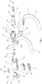
- a handlebar group for bicycles according to the invention is indicated as a whole by number 10.
- Said handlebar group 10 comprises:
- the peculiarity of the handlebar group 10 according to the invention lies in the fact that the first fixing means 18 of the handlebar 11 comprise:
- the central section 12 of the handlebar 11 is therefore locked between the front part 21 of the front tubular body 20 and the front portion 17a of the central extension 17, as clearly visible in Figures 2 , 4 and 5 .
- the second fixing means 19 comprise:
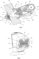
- the tightening rod 23 is positioned to longitudinally cross the central extension 17, as visible in the sections of Figures 4 and 5 , and is configured to connect the front tubular body 20 and the rear tubular body 24.
- the longitudinal direction is intended to be a direction from the front head to the rear collar.
- the central extension 17 is therefore wedged between the front tubular body 20 and the rear tubular body 24.
- This central extension 17 is defined by a tubular body with longitudinal development.
- the handlebar group 10 by mounting and screwing only the tightening rod 23, allows to lock both the first fixing means 18, and thus to tighten the front head 15 on the central section 12 of the handlebar 11, and the second fixing means 19, and thus to tighten the rear collar 16 around the tube C of a fork.
- the front head 15 is intended to comprise the front tubular body 20 and the front portion 17a of the central extension 17.
- the rear collar 16 is intended to comprise the rear tubular body 24 and the rear portion 17b of the central extension 17.
- the tightening rod 23 consists of a screw, the head of which defines the first end 23a of the tightening rod 23 and the shank of which comprises the second end 23b of the same tightening rod 23 ; the head of the screw is housed inside the front tubular body 20.
- the front tubular body 20 has, at the rear part 22 thereof, a rear opening 22a shaped to allow the passage of the shank of the tightening rod 23.
- the handlebar group 10 according to the invention also comprises an anti-unscrewing locking device 25 for the tightening rod 23.
- this anti-unscrewing locking device 25 comprises, inside the front tubular body 20 :
- the central extension 17 comprises, at each of the locking grub screws 28, a lateral through-hole 29 for the passage of a screwing tool for screwing and unscrewing the locking grub screws 28.
- the central section 12 of the handlebar 11 has a first longitudinal through-hole 30, configured to allow the passage of a tool for screwing the tightening rod 23.
- the front part 21 of the front tubular body 20 has a second longitudinal through-hole 31, arranged coaxial to the longitudinal through-hole 30 of the central section 12 of the handlebar 11 ; this second longitudinal through-hole 31 is also configured to allow the passage of a tool for screwing the tightening rod 23.
- the tightening rod 23 has a cylindrical head with a recessed hexagon; for screwing and unscrewing this tightening rod 23, a correspondingly sized Allen key is introduced through the first longitudinal through-hole 30 and the second longitudinal through-hole 31.
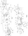
- the handlebar group 10 also comprises a front bracket 36 configured to support an accessory between the lateral gripping sections 13 of the handlebar 11.
- Said front bracket 36 comprises, for example, a supporting appendage 37, fixed at the front to the front tubular body 20, for example by means of a screw 38 screwed to a corresponding hole defined on the plug 32 for closing the second longitudinal through-hole 31.
- the supporting appendage 37 can also be fixed below the front tubular body 20, for example by means of a second screw 39.
- the supporting appendage 37 in turn supports a fixing plate 40, shaped for coupling with a hooking element for fixing an on-board computer, the latter being of a known type.
- the front portion 17a of the central extension 17 has two lateral recesses 50 that are counter-shaped with respect to the surface of the rear face 12b of the central section 12 of the handlebar 11.
- the same front portion 17a also has an upper recess 51 and a lower recess 52, each of which is shaped for coupling with a corresponding stepped portion 53 and 54 defined on the front tubular body 20 ; these details are indicated in Figure 7 .
- the rear tubular body 24 comprises a rear part 24a shaped like a cylindrical arc.
- the front part 24b is defined by a truncated conical relief developing in the forward direction, having a threaded hole 60 configured for screwing with the shank of the tightening rod 23.
- the front part 24b is connected to the rear part 24a by two lateral portions 24c of the rear tubular body 24.
- the rear portion 17b of the central extension 17 has two lateral recesses 70 each of which shaped for coupling with a corresponding stepped portion 24d defined at a lateral portion 24c of the rear tubular body 24.
- the same rear portion 17b also has an upper recess 71 and a lower recess 72, each of which is shaped like an arc of a circle, i.e. configured to rest against the front face C2 of the tube C.
- the handlebar group 10 can also be intended to comprise one or more spacers 80 and 81 for the rear collar 16.
- the handlebar group 10 comprises a cover 82 for the rear collar 16 and a locking screw 83 for locking the cover 82 and for expanding the expander element located inside the rear collar 16, said expander element not being depicted as it is to be understood as being of a known type.
- a handlebar group has been developed which allows for a faster mounting of the handlebar to the handlebar stem and to the fork tube and relative dismounting from them, thanks to the first fixing means for the front head and the second fixing means for the rear collar, which are both operated by means of a single same tightening rod, which allows both to be opened and closed at the same time.
- a handlebar group has been developed which allows the central extension to be mounted and dismounted, which can then be selected at the length most suitable for the user from a plurality of central extensions that are technically equivalent and consistent with the present invention.
- the invention has developed a handlebar group in which the distance between the centre of the rear collar and the centre of the front head can be changed without having to replace the entire handlebar stem, as only the central extension needs to be replaced.
- the invention has developed a handlebar group that is no less robust and reliable than handlebar groups of known type.
- the front part of the handlebar stem head can be shaped in a more aerodynamic and performing way than the handlebar stem heads of known type.
Landscapes
- Engineering & Computer Science (AREA)
- Mechanical Engineering (AREA)
- Steering Devices For Bicycles And Motorcycles (AREA)
- Transition And Organic Metals Composition Catalysts For Addition Polymerization (AREA)
- Footwear And Its Accessory, Manufacturing Method And Apparatuses (AREA)
Claims (10)
- Lenkergruppe (10) für Fahrräder, umfassend:- einen Lenker (11), der einen zentralen Teilbereich (12) zum Befestigen an einem Lenkervorbau (14) und zwei seitliche Griffteilbereiche (13) umfasst;- einen Lenkervorbau (14), der wiederum Folgendes umfasst:dadurch gekennzeichnet, dass die besagten ersten Befestigungsmittel (18) des Lenkers (11) Folgendes umfassen:- einen vorderen Kopf (15), der erste Befestigungsmittel (18) umfasst, die konfiguriert sind, um den besagten Lenker (11) zu arretieren;- einen hinteren Kragen (16), der zweite Befestigungsmittel (19) umfasst, die zum Befestigen an ein Rohr einer Gabel konfiguriert sind;- eine zentrale Verlängerung (17) zur Verbindung zwischen dem besagten vorderen Kopf (15) und dem besagten hinteren Kragen (16);- einen vorderen rohrförmigen Körper (20), der so geformt ist, dass er den besagten zentralen Teilbereich (12) des besagten Lenkers (11) unterbringt, wobei der besagte vordere rohrförmige Körper (20) Folgendes umfasst: ein vorderes Teil (21), das so geformt ist, dass es eine vordere Fläche (12a) des besagten zentralen Teilbereichs (12) umgibt, und ein hinteres Teil (22), das so geformt ist, dass es mit einem ersten Ende (23a) einer Spannstange (23) gekoppelt ist,- und einen vorderen Abschnitt (17a) der besagten zentralen Verlängerung (17), der so geformt ist, dass er auf einer hinteren Fläche (12b) des besagten zentralen Teilbereichs (12) des besagten Lenkers (11) aufliegt;wobei der besagte zentrale Teilbereich (12) des besagten Lenkers (11) zwischen dem besagten vorderen Teil (21) des besagten vorderen rohrförmigen Körpers (20) und dem besagten vorderen Abschnitt (17a) der besagten zentralen Verlängerung (17) arretiert ist;wobei die besagten zweiten Befestigungsmittel (19) Folgendes umfassen:- einen hinteren rohrförmigen Körper (24), der so geformt ist, dass er einen Endteilbereich eines Rohrs einer Gabel unterbringt, wobei der besagte hintere rohrförmige Körper (24) Folgendes umfasst: ein hinteres Teil (24a), das so geformt ist, dass es eine hintere Fläche des besagten Endteilbereichs eines Rohrs einer Gabel umgibt, und ein vorderes Teil (24b), das so geformt ist, dass es mit einem zweiten Ende (23b) der besagten Spannstange (23) gekoppelt ist,- und einen hinteren Abschnitt (17b) der besagten zentralen Verlängerung (17), der so geformt ist, dass er auf einer vorderen Fläche des besagten Endteilbereichs des besagten Rohrs aufliegt;wobei die besagte Spannstange (23) so positioniert ist, dass sie die besagte zentrale Verlängerung (17) längs kreuzt, und so konfiguriert ist, dass sie den besagten vorderen rohrförmigen Körper (20) und den besagten hinteren rohrförmigen Körper (24) verbindet.
- Lenkergruppe nach Patentanspruch 1, dadurch gekennzeichnet, dass die besagte Spannstange (23) einen Hakenkopf und einen Schaft umfasst.
- Lenkergruppe nach einem oder mehreren der vorhergehenden Patentansprüche, dadurch gekennzeichnet, dass der besagte vordere rohrförmige Körper (20) in einem hinteren Teil davon (22) eine hintere Öffnung (22a) aufweist, die so geformt ist, dass sie den Durchgang des besagten Schaftes der besagten Spannstange (23) ermöglicht.
- Lenkergruppe nach einem oder mehreren der vorhergehenden Patentansprüche, dadurch gekennzeichnet, dass sie eine Arretiervorrichtung (25) mit Aufschraubsicherung für die besagte Spannstange (23) umfasst.
- Lenkergruppe nach einem oder mehreren der vorhergehenden Patentansprüche, dadurch gekennzeichnet, dass der besagte zentrale Teilbereich (12) des besagten Lenkers (11) ein erstes Längsdurchgangsloch (30) aufweist, das so konfiguriert ist, dass es den Durchgang eines Werkzeugs zum Verschrauben der besagten Spannstange (23) ermöglicht.
- Lenkergruppe nach einem oder mehreren der vorhergehenden Patentansprüche, dadurch gekennzeichnet, dass das besagte vordere Teil (21) des besagten vorderen rohrförmigen Körpers (20) ein zweites Längsdurchgangsloch (31) aufweist, das koaxial zum besagten ersten Längsdurchgangsloch (30) des besagten zentralen Teilbereichs (12) des besagten Lenkers (11) angeordnet ist, wobei das besagte zweite Längsdurchgangsloch (31) so konfiguriert ist, dass es den Durchgang eines Werkzeugs zum Verschrauben der Spannstange (23) ermöglicht.
- Lenkergruppe nach einem oder mehreren der vorhergehenden Patentansprüche, dadurch gekennzeichnet, dass der besagte vordere Abschnitt (17a) der besagten zentralen Verlängerung (17) zwei seitliche Aussparungen (50) aufweist, die in Bezug auf die Oberfläche der hinteren Fläche (12b) des zentralen Teilbereichs (12) des Lenkers (11) gegengeformt sind.
- Lenkergruppe nach einem oder mehreren der vorhergehenden Patentansprüche, dadurch gekennzeichnet, dass der besagte vordere Abschnitt (17a) eine obere Aussparung (51) und eine untere Aussparung (52) aufweist, von denen jede zum Koppeln mit einem entsprechenden Stufenabschnitt (53, 54), der am besagten vorderen rohrförmigen Körper (20) definiert ist, geformt ist.
- Lenkergruppe nach einem oder mehreren der vorhergehenden Patentansprüche, dadurch gekennzeichnet, dass der besagte hintere rohrförmige Körper (24) ein zylinderbogenförmiges hinteres Teil (24a) umfasst, wobei das besagte vordere Teil (24b) durch ein kegelstumpfförmiges Relief, das sich vorwärts entwickelt, definiert ist, das ein Gewindeloch (60) aufweist, das konfiguriert ist, um die besagte Spannstange (23) mit dem besagten Schaft zu verschrauben, wobei das besagte vordere Teil (24b) mit dem besagten hinteren Teil (24a) über zwei seitliche Abschnitte (24c) des besagten hinteren rohrförmigen Körpers (24) verbunden ist.
- Lenkergruppe nach einem oder mehreren der vorhergehenden Patentansprüche, dadurch gekennzeichnet, dass der besagte hintere Abschnitt (17b) der besagten zentralen Verlängerung (17) zwei seitliche Aussparungen (70) aufweist, von denen jede zum Koppeln mit einem entsprechenden Stufenabschnitt (24d) geformt ist, der an einem seitlichen Abschnitt (24c) des besagten hinteren rohrförmigen Körpers (24) definiert ist, wobei der besagte hintere Abschnitt (17b) eine obere Aussparung (71) und eine untere Aussparung (72) aufweist, von denen jede wie ein Kreisbogen geformt ist, der so konfiguriert ist, dass er an einer vorderen Fläche eines Rohrs einer Gabel anliegt.
Applications Claiming Priority (2)
| Application Number | Priority Date | Filing Date | Title |
|---|---|---|---|
| IT102021000001697A IT202100001697A1 (it) | 2021-01-28 | 2021-01-28 | Gruppo manubrio per biciclette |
| PCT/IB2022/050723 WO2022162579A1 (en) | 2021-01-28 | 2022-01-27 | Bicycle handlebar stem |
Publications (2)
| Publication Number | Publication Date |
|---|---|
| EP4284702A1 EP4284702A1 (de) | 2023-12-06 |
| EP4284702B1 true EP4284702B1 (de) | 2025-01-22 |
Family
ID=75439277
Family Applications (1)
| Application Number | Title | Priority Date | Filing Date |
|---|---|---|---|
| EP22705135.6A Active EP4284702B1 (de) | 2021-01-28 | 2022-01-27 | Fahrradlenker-vorbau |
Country Status (3)
| Country | Link |
|---|---|
| EP (1) | EP4284702B1 (de) |
| IT (1) | IT202100001697A1 (de) |
| WO (1) | WO2022162579A1 (de) |
Families Citing this family (1)
| Publication number | Priority date | Publication date | Assignee | Title |
|---|---|---|---|---|
| IT202300021747A1 (it) * | 2023-10-18 | 2025-04-18 | Colnago Ernesto E C S R L | Attacco manubrio per bicicletta perfezionato |
Family Cites Families (2)
| Publication number | Priority date | Publication date | Assignee | Title |
|---|---|---|---|---|
| FR2786155B1 (fr) * | 1998-11-19 | 2001-01-12 | Time Sport Int | Dispositif de fixation d'une potence de bicyclette sur un pivot de fourche, et potence pour etre fixee avec un tel dispositif |
| CN108749987A (zh) * | 2018-07-13 | 2018-11-06 | 天津锦利来金属制品有限公司 | 一种自行车把立锁紧装置 |
-
2021
- 2021-01-28 IT IT102021000001697A patent/IT202100001697A1/it unknown
-
2022
- 2022-01-27 EP EP22705135.6A patent/EP4284702B1/de active Active
- 2022-01-27 WO PCT/IB2022/050723 patent/WO2022162579A1/en not_active Ceased
Also Published As
| Publication number | Publication date |
|---|---|
| WO2022162579A1 (en) | 2022-08-04 |
| IT202100001697A1 (it) | 2022-07-28 |
| EP4284702A1 (de) | 2023-12-06 |
Similar Documents
| Publication | Publication Date | Title |
|---|---|---|
| US6293450B1 (en) | Quick release mechanism for motorcycle saddlebag | |
| US5803329A (en) | Carrier rack for a two-wheeled vehicle, in particular for a bicycle | |
| US4770435A (en) | Freestyle bicycle construction | |
| EP4209410B1 (de) | Multi-werkzeug-anordnung und multi-werkzeugaufbewahrungs-anordnung | |
| US6482115B2 (en) | Cable connecting apparatus for a bicycle component | |
| US8590418B2 (en) | Adjusting mechanism for handle position of bicycle | |
| EP4284702B1 (de) | Fahrradlenker-vorbau | |
| US10173747B2 (en) | Quick release through axle with locking elements for bikes | |
| US7353731B2 (en) | Quick release handlebar stem assembly for a bicycle | |
| US20090236817A1 (en) | Bicycle Fork and Steering Tube | |
| US9415825B1 (en) | Combination bicycle handlebar and stem assembly | |
| US5265496A (en) | Clamp-on aero bar with internal clamping mechanism for attachment to a bicycle handlebar | |
| US8640935B2 (en) | Mounting assembly for child's bicycle seat | |
| US5598744A (en) | Racing handlebar structure suitable for rotation shifters disposed thereto | |
| US12337923B2 (en) | Steering bearing assembly with internal cable routing | |
| US20080219760A1 (en) | Fixing base for bike auxiliary handle bar | |
| US10046825B1 (en) | Adjustable bicycle handlebar stem assembly | |
| US5732601A (en) | Coupling device for brake cables of bicycles | |
| NO165389B (no) | Festeinnretning for feste av en sykkelbagasjebaerer | |
| US5553960A (en) | Field serviceable derailleur device | |
| EP3434572B1 (de) | Verstellbare fahrradlenkervorbauanordnung | |
| EP3441294A1 (de) | Fahrradkomponente mit einer abnehmbaren klemmvorrichtung zur befestigung an einem rohrförmigen element des fahrrads | |
| US6994366B2 (en) | Flush mount fork tube cap nut for the triple of a motorcycle | |
| EP2103510B1 (de) | Fahrradzubehörvorrichtung | |
| CN206734465U (zh) | 一种自行车把立结构 |
Legal Events
| Date | Code | Title | Description |
|---|---|---|---|
| STAA | Information on the status of an ep patent application or granted ep patent |
Free format text: STATUS: UNKNOWN |
|
| STAA | Information on the status of an ep patent application or granted ep patent |
Free format text: STATUS: THE INTERNATIONAL PUBLICATION HAS BEEN MADE |
|
| PUAI | Public reference made under article 153(3) epc to a published international application that has entered the european phase |
Free format text: ORIGINAL CODE: 0009012 |
|
| STAA | Information on the status of an ep patent application or granted ep patent |
Free format text: STATUS: REQUEST FOR EXAMINATION WAS MADE |
|
| 17P | Request for examination filed |
Effective date: 20230803 |
|
| AK | Designated contracting states |
Kind code of ref document: A1 Designated state(s): AL AT BE BG CH CY CZ DE DK EE ES FI FR GB GR HR HU IE IS IT LI LT LU LV MC MK MT NL NO PL PT RO RS SE SI SK SM TR |
|
| DAV | Request for validation of the european patent (deleted) | ||
| DAX | Request for extension of the european patent (deleted) | ||
| GRAP | Despatch of communication of intention to grant a patent |
Free format text: ORIGINAL CODE: EPIDOSNIGR1 |
|
| STAA | Information on the status of an ep patent application or granted ep patent |
Free format text: STATUS: GRANT OF PATENT IS INTENDED |
|
| INTG | Intention to grant announced |
Effective date: 20240813 |
|
| GRAS | Grant fee paid |
Free format text: ORIGINAL CODE: EPIDOSNIGR3 |
|
| GRAA | (expected) grant |
Free format text: ORIGINAL CODE: 0009210 |
|
| STAA | Information on the status of an ep patent application or granted ep patent |
Free format text: STATUS: THE PATENT HAS BEEN GRANTED |
|
| RAP3 | Party data changed (applicant data changed or rights of an application transferred) |
Owner name: URSUS S.P.A. |
|
| RIN1 | Information on inventor provided before grant (corrected) |
Inventor name: FERRONATO, SIMONE Inventor name: GENOVESE, MARCO Inventor name: FERRONATO, SERGIO Inventor name: FERRONATO, MIRKO |
|
| AK | Designated contracting states |
Kind code of ref document: B1 Designated state(s): AL AT BE BG CH CY CZ DE DK EE ES FI FR GB GR HR HU IE IS IT LI LT LU LV MC MK MT NL NO PL PT RO RS SE SI SK SM TR |
|
| REG | Reference to a national code |
Ref country code: GB Ref legal event code: FG4D |
|
| REG | Reference to a national code |
Ref country code: CH Ref legal event code: EP |
|
| REG | Reference to a national code |
Ref country code: IE Ref legal event code: FG4D |
|
| REG | Reference to a national code |
Ref country code: DE Ref legal event code: R096 Ref document number: 602022009795 Country of ref document: DE |
|
| REG | Reference to a national code |
Ref country code: DE Ref legal event code: R081 Ref document number: 602022009795 Country of ref document: DE Owner name: URSUS S.P.A., ROSA, IT Free format text: FORMER OWNERS: MARCHIORO, PAOLO, 36100 VICENZA, IT; URSUS S.P.A., ROSA, VICENZA, IT |
|
| PGFP | Annual fee paid to national office [announced via postgrant information from national office to epo] |
Ref country code: DE Payment date: 20250319 Year of fee payment: 4 |
|
| PGFP | Annual fee paid to national office [announced via postgrant information from national office to epo] |
Ref country code: AT Payment date: 20250417 Year of fee payment: 4 |
|
| P01 | Opt-out of the competence of the unified patent court (upc) registered |
Free format text: CASE NUMBER: APP_15352/2025 Effective date: 20250328 |
|
| REG | Reference to a national code |
Ref country code: NL Ref legal event code: MP Effective date: 20250122 |
|
| PG25 | Lapsed in a contracting state [announced via postgrant information from national office to epo] |
Ref country code: NL Free format text: LAPSE BECAUSE OF FAILURE TO SUBMIT A TRANSLATION OF THE DESCRIPTION OR TO PAY THE FEE WITHIN THE PRESCRIBED TIME-LIMIT Effective date: 20250122 |
|
| PG25 | Lapsed in a contracting state [announced via postgrant information from national office to epo] |
Ref country code: RS Free format text: LAPSE BECAUSE OF FAILURE TO SUBMIT A TRANSLATION OF THE DESCRIPTION OR TO PAY THE FEE WITHIN THE PRESCRIBED TIME-LIMIT Effective date: 20250422 |
|
| PG25 | Lapsed in a contracting state [announced via postgrant information from national office to epo] |
Ref country code: FI Free format text: LAPSE BECAUSE OF FAILURE TO SUBMIT A TRANSLATION OF THE DESCRIPTION OR TO PAY THE FEE WITHIN THE PRESCRIBED TIME-LIMIT Effective date: 20250122 |
|
| PG25 | Lapsed in a contracting state [announced via postgrant information from national office to epo] |
Ref country code: PL Free format text: LAPSE BECAUSE OF FAILURE TO SUBMIT A TRANSLATION OF THE DESCRIPTION OR TO PAY THE FEE WITHIN THE PRESCRIBED TIME-LIMIT Effective date: 20250122 |
|
| PG25 | Lapsed in a contracting state [announced via postgrant information from national office to epo] |
Ref country code: ES Free format text: LAPSE BECAUSE OF FAILURE TO SUBMIT A TRANSLATION OF THE DESCRIPTION OR TO PAY THE FEE WITHIN THE PRESCRIBED TIME-LIMIT Effective date: 20250122 |
|
| REG | Reference to a national code |
Ref country code: LT Ref legal event code: MG9D |
|
| PG25 | Lapsed in a contracting state [announced via postgrant information from national office to epo] |
Ref country code: IS Free format text: LAPSE BECAUSE OF FAILURE TO SUBMIT A TRANSLATION OF THE DESCRIPTION OR TO PAY THE FEE WITHIN THE PRESCRIBED TIME-LIMIT Effective date: 20250522 Ref country code: NO Free format text: LAPSE BECAUSE OF FAILURE TO SUBMIT A TRANSLATION OF THE DESCRIPTION OR TO PAY THE FEE WITHIN THE PRESCRIBED TIME-LIMIT Effective date: 20250422 |
|
| REG | Reference to a national code |
Ref country code: AT Ref legal event code: MK05 Ref document number: 1761290 Country of ref document: AT Kind code of ref document: T Effective date: 20250122 |
|
| PG25 | Lapsed in a contracting state [announced via postgrant information from national office to epo] |
Ref country code: HR Free format text: LAPSE BECAUSE OF FAILURE TO SUBMIT A TRANSLATION OF THE DESCRIPTION OR TO PAY THE FEE WITHIN THE PRESCRIBED TIME-LIMIT Effective date: 20250122 |
|
| PG25 | Lapsed in a contracting state [announced via postgrant information from national office to epo] |
Ref country code: LV Free format text: LAPSE BECAUSE OF FAILURE TO SUBMIT A TRANSLATION OF THE DESCRIPTION OR TO PAY THE FEE WITHIN THE PRESCRIBED TIME-LIMIT Effective date: 20250122 Ref country code: PT Free format text: LAPSE BECAUSE OF FAILURE TO SUBMIT A TRANSLATION OF THE DESCRIPTION OR TO PAY THE FEE WITHIN THE PRESCRIBED TIME-LIMIT Effective date: 20250522 |
|
| PG25 | Lapsed in a contracting state [announced via postgrant information from national office to epo] |
Ref country code: GR Free format text: LAPSE BECAUSE OF FAILURE TO SUBMIT A TRANSLATION OF THE DESCRIPTION OR TO PAY THE FEE WITHIN THE PRESCRIBED TIME-LIMIT Effective date: 20250423 Ref country code: BG Free format text: LAPSE BECAUSE OF FAILURE TO SUBMIT A TRANSLATION OF THE DESCRIPTION OR TO PAY THE FEE WITHIN THE PRESCRIBED TIME-LIMIT Effective date: 20250122 |
|
| PG25 | Lapsed in a contracting state [announced via postgrant information from national office to epo] |
Ref country code: AT Free format text: LAPSE BECAUSE OF FAILURE TO SUBMIT A TRANSLATION OF THE DESCRIPTION OR TO PAY THE FEE WITHIN THE PRESCRIBED TIME-LIMIT Effective date: 20250122 |
|
| REG | Reference to a national code |
Ref country code: CH Ref legal event code: PL |
|
| PG25 | Lapsed in a contracting state [announced via postgrant information from national office to epo] |
Ref country code: SE Free format text: LAPSE BECAUSE OF FAILURE TO SUBMIT A TRANSLATION OF THE DESCRIPTION OR TO PAY THE FEE WITHIN THE PRESCRIBED TIME-LIMIT Effective date: 20250122 |
|
| PG25 | Lapsed in a contracting state [announced via postgrant information from national office to epo] |
Ref country code: LU Free format text: LAPSE BECAUSE OF NON-PAYMENT OF DUE FEES Effective date: 20250127 |
|
| PG25 | Lapsed in a contracting state [announced via postgrant information from national office to epo] |
Ref country code: SM Free format text: LAPSE BECAUSE OF FAILURE TO SUBMIT A TRANSLATION OF THE DESCRIPTION OR TO PAY THE FEE WITHIN THE PRESCRIBED TIME-LIMIT Effective date: 20250122 |
|
| PG25 | Lapsed in a contracting state [announced via postgrant information from national office to epo] |
Ref country code: DK Free format text: LAPSE BECAUSE OF FAILURE TO SUBMIT A TRANSLATION OF THE DESCRIPTION OR TO PAY THE FEE WITHIN THE PRESCRIBED TIME-LIMIT Effective date: 20250122 |
|
| PG25 | Lapsed in a contracting state [announced via postgrant information from national office to epo] |
Ref country code: MC Free format text: LAPSE BECAUSE OF FAILURE TO SUBMIT A TRANSLATION OF THE DESCRIPTION OR TO PAY THE FEE WITHIN THE PRESCRIBED TIME-LIMIT Effective date: 20250122 |
|
| PG25 | Lapsed in a contracting state [announced via postgrant information from national office to epo] |
Ref country code: IT Free format text: LAPSE BECAUSE OF FAILURE TO SUBMIT A TRANSLATION OF THE DESCRIPTION OR TO PAY THE FEE WITHIN THE PRESCRIBED TIME-LIMIT Effective date: 20250122 |
|
| PG25 | Lapsed in a contracting state [announced via postgrant information from national office to epo] |
Ref country code: BE Free format text: LAPSE BECAUSE OF NON-PAYMENT OF DUE FEES Effective date: 20250131 |
|
| PG25 | Lapsed in a contracting state [announced via postgrant information from national office to epo] |
Ref country code: CH Free format text: LAPSE BECAUSE OF NON-PAYMENT OF DUE FEES Effective date: 20250131 |
|
| PG25 | Lapsed in a contracting state [announced via postgrant information from national office to epo] |
Ref country code: EE Free format text: LAPSE BECAUSE OF FAILURE TO SUBMIT A TRANSLATION OF THE DESCRIPTION OR TO PAY THE FEE WITHIN THE PRESCRIBED TIME-LIMIT Effective date: 20250122 Ref country code: CZ Free format text: LAPSE BECAUSE OF FAILURE TO SUBMIT A TRANSLATION OF THE DESCRIPTION OR TO PAY THE FEE WITHIN THE PRESCRIBED TIME-LIMIT Effective date: 20250122 |
|
| REG | Reference to a national code |
Ref country code: BE Ref legal event code: MM Effective date: 20250131 Ref country code: DE Ref legal event code: R097 Ref document number: 602022009795 Country of ref document: DE |
|
| PG25 | Lapsed in a contracting state [announced via postgrant information from national office to epo] |
Ref country code: RO Free format text: LAPSE BECAUSE OF FAILURE TO SUBMIT A TRANSLATION OF THE DESCRIPTION OR TO PAY THE FEE WITHIN THE PRESCRIBED TIME-LIMIT Effective date: 20250122 |
|
| PG25 | Lapsed in a contracting state [announced via postgrant information from national office to epo] |
Ref country code: SK Free format text: LAPSE BECAUSE OF FAILURE TO SUBMIT A TRANSLATION OF THE DESCRIPTION OR TO PAY THE FEE WITHIN THE PRESCRIBED TIME-LIMIT Effective date: 20250122 |
|
| PLBE | No opposition filed within time limit |
Free format text: ORIGINAL CODE: 0009261 |
|
| STAA | Information on the status of an ep patent application or granted ep patent |
Free format text: STATUS: NO OPPOSITION FILED WITHIN TIME LIMIT |