EP4284637B1 - Verbundscheibe mit verbesserter farbwirkung - Google Patents
Verbundscheibe mit verbesserter farbwirkung Download PDFInfo
- Publication number
- EP4284637B1 EP4284637B1 EP22701179.8A EP22701179A EP4284637B1 EP 4284637 B1 EP4284637 B1 EP 4284637B1 EP 22701179 A EP22701179 A EP 22701179A EP 4284637 B1 EP4284637 B1 EP 4284637B1
- Authority
- EP
- European Patent Office
- Prior art keywords
- refractive index
- film
- pane
- thermoplastic
- layer
- Prior art date
- Legal status (The legal status is an assumption and is not a legal conclusion. Google has not performed a legal analysis and makes no representation as to the accuracy of the status listed.)
- Active
Links
Images


Classifications
-
- B—PERFORMING OPERATIONS; TRANSPORTING
- B32—LAYERED PRODUCTS
- B32B—LAYERED PRODUCTS, i.e. PRODUCTS BUILT-UP OF STRATA OF FLAT OR NON-FLAT, e.g. CELLULAR OR HONEYCOMB, FORM
- B32B1/00—Layered products having a non-planar shape
-
- B—PERFORMING OPERATIONS; TRANSPORTING
- B32—LAYERED PRODUCTS
- B32B—LAYERED PRODUCTS, i.e. PRODUCTS BUILT-UP OF STRATA OF FLAT OR NON-FLAT, e.g. CELLULAR OR HONEYCOMB, FORM
- B32B17/00—Layered products essentially comprising sheet glass, or glass, slag, or like fibres
- B32B17/06—Layered products essentially comprising sheet glass, or glass, slag, or like fibres comprising glass as the main or only constituent of a layer, next to another layer of a specific material
- B32B17/10—Layered products essentially comprising sheet glass, or glass, slag, or like fibres comprising glass as the main or only constituent of a layer, next to another layer of a specific material of synthetic resin
- B32B17/10005—Layered products essentially comprising sheet glass, or glass, slag, or like fibres comprising glass as the main or only constituent of a layer, next to another layer of a specific material of synthetic resin laminated safety glass or glazing
- B32B17/10009—Layered products essentially comprising sheet glass, or glass, slag, or like fibres comprising glass as the main or only constituent of a layer, next to another layer of a specific material of synthetic resin laminated safety glass or glazing characterized by the number, the constitution or treatment of glass sheets
- B32B17/10036—Layered products essentially comprising sheet glass, or glass, slag, or like fibres comprising glass as the main or only constituent of a layer, next to another layer of a specific material of synthetic resin laminated safety glass or glazing characterized by the number, the constitution or treatment of glass sheets comprising two outer glass sheets
-
- B—PERFORMING OPERATIONS; TRANSPORTING
- B32—LAYERED PRODUCTS
- B32B—LAYERED PRODUCTS, i.e. PRODUCTS BUILT-UP OF STRATA OF FLAT OR NON-FLAT, e.g. CELLULAR OR HONEYCOMB, FORM
- B32B17/00—Layered products essentially comprising sheet glass, or glass, slag, or like fibres
- B32B17/06—Layered products essentially comprising sheet glass, or glass, slag, or like fibres comprising glass as the main or only constituent of a layer, next to another layer of a specific material
- B32B17/10—Layered products essentially comprising sheet glass, or glass, slag, or like fibres comprising glass as the main or only constituent of a layer, next to another layer of a specific material of synthetic resin
- B32B17/10005—Layered products essentially comprising sheet glass, or glass, slag, or like fibres comprising glass as the main or only constituent of a layer, next to another layer of a specific material of synthetic resin laminated safety glass or glazing
- B32B17/10165—Functional features of the laminated safety glass or glazing
- B32B17/10174—Coatings of a metallic or dielectric material on a constituent layer of glass or polymer
- B32B17/10201—Dielectric coatings
-
- B—PERFORMING OPERATIONS; TRANSPORTING
- B32—LAYERED PRODUCTS
- B32B—LAYERED PRODUCTS, i.e. PRODUCTS BUILT-UP OF STRATA OF FLAT OR NON-FLAT, e.g. CELLULAR OR HONEYCOMB, FORM
- B32B17/00—Layered products essentially comprising sheet glass, or glass, slag, or like fibres
- B32B17/06—Layered products essentially comprising sheet glass, or glass, slag, or like fibres comprising glass as the main or only constituent of a layer, next to another layer of a specific material
- B32B17/10—Layered products essentially comprising sheet glass, or glass, slag, or like fibres comprising glass as the main or only constituent of a layer, next to another layer of a specific material of synthetic resin
- B32B17/10005—Layered products essentially comprising sheet glass, or glass, slag, or like fibres comprising glass as the main or only constituent of a layer, next to another layer of a specific material of synthetic resin laminated safety glass or glazing
- B32B17/10165—Functional features of the laminated safety glass or glazing
- B32B17/10174—Coatings of a metallic or dielectric material on a constituent layer of glass or polymer
- B32B17/1022—Metallic coatings
- B32B17/10229—Metallic layers sandwiched by dielectric layers
-
- B—PERFORMING OPERATIONS; TRANSPORTING
- B32—LAYERED PRODUCTS
- B32B—LAYERED PRODUCTS, i.e. PRODUCTS BUILT-UP OF STRATA OF FLAT OR NON-FLAT, e.g. CELLULAR OR HONEYCOMB, FORM
- B32B17/00—Layered products essentially comprising sheet glass, or glass, slag, or like fibres
- B32B17/06—Layered products essentially comprising sheet glass, or glass, slag, or like fibres comprising glass as the main or only constituent of a layer, next to another layer of a specific material
- B32B17/10—Layered products essentially comprising sheet glass, or glass, slag, or like fibres comprising glass as the main or only constituent of a layer, next to another layer of a specific material of synthetic resin
- B32B17/10005—Layered products essentially comprising sheet glass, or glass, slag, or like fibres comprising glass as the main or only constituent of a layer, next to another layer of a specific material of synthetic resin laminated safety glass or glazing
- B32B17/10165—Functional features of the laminated safety glass or glazing
- B32B17/10431—Specific parts for the modulation of light incorporated into the laminated safety glass or glazing
- B32B17/1044—Invariable transmission
- B32B17/10449—Wavelength selective transmission
-
- B—PERFORMING OPERATIONS; TRANSPORTING
- B32—LAYERED PRODUCTS
- B32B—LAYERED PRODUCTS, i.e. PRODUCTS BUILT-UP OF STRATA OF FLAT OR NON-FLAT, e.g. CELLULAR OR HONEYCOMB, FORM
- B32B17/00—Layered products essentially comprising sheet glass, or glass, slag, or like fibres
- B32B17/06—Layered products essentially comprising sheet glass, or glass, slag, or like fibres comprising glass as the main or only constituent of a layer, next to another layer of a specific material
- B32B17/10—Layered products essentially comprising sheet glass, or glass, slag, or like fibres comprising glass as the main or only constituent of a layer, next to another layer of a specific material of synthetic resin
- B32B17/10005—Layered products essentially comprising sheet glass, or glass, slag, or like fibres comprising glass as the main or only constituent of a layer, next to another layer of a specific material of synthetic resin laminated safety glass or glazing
- B32B17/1055—Layered products essentially comprising sheet glass, or glass, slag, or like fibres comprising glass as the main or only constituent of a layer, next to another layer of a specific material of synthetic resin laminated safety glass or glazing characterized by the resin layer, i.e. interlayer
- B32B17/10614—Layered products essentially comprising sheet glass, or glass, slag, or like fibres comprising glass as the main or only constituent of a layer, next to another layer of a specific material of synthetic resin laminated safety glass or glazing characterized by the resin layer, i.e. interlayer comprising particles for purposes other than dyeing
-
- B—PERFORMING OPERATIONS; TRANSPORTING
- B32—LAYERED PRODUCTS
- B32B—LAYERED PRODUCTS, i.e. PRODUCTS BUILT-UP OF STRATA OF FLAT OR NON-FLAT, e.g. CELLULAR OR HONEYCOMB, FORM
- B32B17/00—Layered products essentially comprising sheet glass, or glass, slag, or like fibres
- B32B17/06—Layered products essentially comprising sheet glass, or glass, slag, or like fibres comprising glass as the main or only constituent of a layer, next to another layer of a specific material
- B32B17/10—Layered products essentially comprising sheet glass, or glass, slag, or like fibres comprising glass as the main or only constituent of a layer, next to another layer of a specific material of synthetic resin
- B32B17/10005—Layered products essentially comprising sheet glass, or glass, slag, or like fibres comprising glass as the main or only constituent of a layer, next to another layer of a specific material of synthetic resin laminated safety glass or glazing
- B32B17/1055—Layered products essentially comprising sheet glass, or glass, slag, or like fibres comprising glass as the main or only constituent of a layer, next to another layer of a specific material of synthetic resin laminated safety glass or glazing characterized by the resin layer, i.e. interlayer
- B32B17/10761—Layered products essentially comprising sheet glass, or glass, slag, or like fibres comprising glass as the main or only constituent of a layer, next to another layer of a specific material of synthetic resin laminated safety glass or glazing characterized by the resin layer, i.e. interlayer containing vinyl acetal
-
- B—PERFORMING OPERATIONS; TRANSPORTING
- B32—LAYERED PRODUCTS
- B32B—LAYERED PRODUCTS, i.e. PRODUCTS BUILT-UP OF STRATA OF FLAT OR NON-FLAT, e.g. CELLULAR OR HONEYCOMB, FORM
- B32B17/00—Layered products essentially comprising sheet glass, or glass, slag, or like fibres
- B32B17/06—Layered products essentially comprising sheet glass, or glass, slag, or like fibres comprising glass as the main or only constituent of a layer, next to another layer of a specific material
- B32B17/10—Layered products essentially comprising sheet glass, or glass, slag, or like fibres comprising glass as the main or only constituent of a layer, next to another layer of a specific material of synthetic resin
- B32B17/10005—Layered products essentially comprising sheet glass, or glass, slag, or like fibres comprising glass as the main or only constituent of a layer, next to another layer of a specific material of synthetic resin laminated safety glass or glazing
- B32B17/1055—Layered products essentially comprising sheet glass, or glass, slag, or like fibres comprising glass as the main or only constituent of a layer, next to another layer of a specific material of synthetic resin laminated safety glass or glazing characterized by the resin layer, i.e. interlayer
- B32B17/1077—Layered products essentially comprising sheet glass, or glass, slag, or like fibres comprising glass as the main or only constituent of a layer, next to another layer of a specific material of synthetic resin laminated safety glass or glazing characterized by the resin layer, i.e. interlayer containing polyurethane
-
- B—PERFORMING OPERATIONS; TRANSPORTING
- B32—LAYERED PRODUCTS
- B32B—LAYERED PRODUCTS, i.e. PRODUCTS BUILT-UP OF STRATA OF FLAT OR NON-FLAT, e.g. CELLULAR OR HONEYCOMB, FORM
- B32B17/00—Layered products essentially comprising sheet glass, or glass, slag, or like fibres
- B32B17/06—Layered products essentially comprising sheet glass, or glass, slag, or like fibres comprising glass as the main or only constituent of a layer, next to another layer of a specific material
- B32B17/10—Layered products essentially comprising sheet glass, or glass, slag, or like fibres comprising glass as the main or only constituent of a layer, next to another layer of a specific material of synthetic resin
- B32B17/10005—Layered products essentially comprising sheet glass, or glass, slag, or like fibres comprising glass as the main or only constituent of a layer, next to another layer of a specific material of synthetic resin laminated safety glass or glazing
- B32B17/1055—Layered products essentially comprising sheet glass, or glass, slag, or like fibres comprising glass as the main or only constituent of a layer, next to another layer of a specific material of synthetic resin laminated safety glass or glazing characterized by the resin layer, i.e. interlayer
- B32B17/10788—Layered products essentially comprising sheet glass, or glass, slag, or like fibres comprising glass as the main or only constituent of a layer, next to another layer of a specific material of synthetic resin laminated safety glass or glazing characterized by the resin layer, i.e. interlayer containing ethylene vinylacetate
-
- B—PERFORMING OPERATIONS; TRANSPORTING
- B32—LAYERED PRODUCTS
- B32B—LAYERED PRODUCTS, i.e. PRODUCTS BUILT-UP OF STRATA OF FLAT OR NON-FLAT, e.g. CELLULAR OR HONEYCOMB, FORM
- B32B17/00—Layered products essentially comprising sheet glass, or glass, slag, or like fibres
- B32B17/06—Layered products essentially comprising sheet glass, or glass, slag, or like fibres comprising glass as the main or only constituent of a layer, next to another layer of a specific material
- B32B17/10—Layered products essentially comprising sheet glass, or glass, slag, or like fibres comprising glass as the main or only constituent of a layer, next to another layer of a specific material of synthetic resin
- B32B17/10005—Layered products essentially comprising sheet glass, or glass, slag, or like fibres comprising glass as the main or only constituent of a layer, next to another layer of a specific material of synthetic resin laminated safety glass or glazing
- B32B17/10807—Making laminated safety glass or glazing; Apparatus therefor
- B32B17/10816—Making laminated safety glass or glazing; Apparatus therefor by pressing
-
- B—PERFORMING OPERATIONS; TRANSPORTING
- B32—LAYERED PRODUCTS
- B32B—LAYERED PRODUCTS, i.e. PRODUCTS BUILT-UP OF STRATA OF FLAT OR NON-FLAT, e.g. CELLULAR OR HONEYCOMB, FORM
- B32B17/00—Layered products essentially comprising sheet glass, or glass, slag, or like fibres
- B32B17/06—Layered products essentially comprising sheet glass, or glass, slag, or like fibres comprising glass as the main or only constituent of a layer, next to another layer of a specific material
- B32B17/10—Layered products essentially comprising sheet glass, or glass, slag, or like fibres comprising glass as the main or only constituent of a layer, next to another layer of a specific material of synthetic resin
- B32B17/10005—Layered products essentially comprising sheet glass, or glass, slag, or like fibres comprising glass as the main or only constituent of a layer, next to another layer of a specific material of synthetic resin laminated safety glass or glazing
- B32B17/10807—Making laminated safety glass or glazing; Apparatus therefor
- B32B17/10899—Making laminated safety glass or glazing; Apparatus therefor by introducing interlayers of synthetic resin
- B32B17/10935—Making laminated safety glass or glazing; Apparatus therefor by introducing interlayers of synthetic resin as a preformed layer, e.g. formed by extrusion
-
- B—PERFORMING OPERATIONS; TRANSPORTING
- B32—LAYERED PRODUCTS
- B32B—LAYERED PRODUCTS, i.e. PRODUCTS BUILT-UP OF STRATA OF FLAT OR NON-FLAT, e.g. CELLULAR OR HONEYCOMB, FORM
- B32B27/00—Layered products comprising a layer of synthetic resin
- B32B27/06—Layered products comprising a layer of synthetic resin as the main or only constituent of a layer, which is next to another layer of the same or of a different material
- B32B27/08—Layered products comprising a layer of synthetic resin as the main or only constituent of a layer, which is next to another layer of the same or of a different material of synthetic resin
-
- B—PERFORMING OPERATIONS; TRANSPORTING
- B32—LAYERED PRODUCTS
- B32B—LAYERED PRODUCTS, i.e. PRODUCTS BUILT-UP OF STRATA OF FLAT OR NON-FLAT, e.g. CELLULAR OR HONEYCOMB, FORM
- B32B27/00—Layered products comprising a layer of synthetic resin
- B32B27/18—Layered products comprising a layer of synthetic resin characterised by the use of special additives
-
- B—PERFORMING OPERATIONS; TRANSPORTING
- B32—LAYERED PRODUCTS
- B32B—LAYERED PRODUCTS, i.e. PRODUCTS BUILT-UP OF STRATA OF FLAT OR NON-FLAT, e.g. CELLULAR OR HONEYCOMB, FORM
- B32B27/00—Layered products comprising a layer of synthetic resin
- B32B27/30—Layered products comprising a layer of synthetic resin comprising vinyl (co)polymers; comprising acrylic (co)polymers
-
- B—PERFORMING OPERATIONS; TRANSPORTING
- B32—LAYERED PRODUCTS
- B32B—LAYERED PRODUCTS, i.e. PRODUCTS BUILT-UP OF STRATA OF FLAT OR NON-FLAT, e.g. CELLULAR OR HONEYCOMB, FORM
- B32B27/00—Layered products comprising a layer of synthetic resin
- B32B27/30—Layered products comprising a layer of synthetic resin comprising vinyl (co)polymers; comprising acrylic (co)polymers
- B32B27/306—Layered products comprising a layer of synthetic resin comprising vinyl (co)polymers; comprising acrylic (co)polymers comprising vinyl acetate or vinyl alcohol (co)polymers
-
- B—PERFORMING OPERATIONS; TRANSPORTING
- B32—LAYERED PRODUCTS
- B32B—LAYERED PRODUCTS, i.e. PRODUCTS BUILT-UP OF STRATA OF FLAT OR NON-FLAT, e.g. CELLULAR OR HONEYCOMB, FORM
- B32B27/00—Layered products comprising a layer of synthetic resin
- B32B27/36—Layered products comprising a layer of synthetic resin comprising polyesters
-
- B—PERFORMING OPERATIONS; TRANSPORTING
- B32—LAYERED PRODUCTS
- B32B—LAYERED PRODUCTS, i.e. PRODUCTS BUILT-UP OF STRATA OF FLAT OR NON-FLAT, e.g. CELLULAR OR HONEYCOMB, FORM
- B32B27/00—Layered products comprising a layer of synthetic resin
- B32B27/40—Layered products comprising a layer of synthetic resin comprising polyurethanes
-
- B—PERFORMING OPERATIONS; TRANSPORTING
- B32—LAYERED PRODUCTS
- B32B—LAYERED PRODUCTS, i.e. PRODUCTS BUILT-UP OF STRATA OF FLAT OR NON-FLAT, e.g. CELLULAR OR HONEYCOMB, FORM
- B32B7/00—Layered products characterised by the relation between layers; Layered products characterised by the relative orientation of features between layers, or by the relative values of a measurable parameter between layers, i.e. products comprising layers having different physical, chemical or physicochemical properties; Layered products characterised by the interconnection of layers
- B32B7/04—Interconnection of layers
- B32B7/12—Interconnection of layers using interposed adhesives or interposed materials with bonding properties
-
- C—CHEMISTRY; METALLURGY
- C03—GLASS; MINERAL OR SLAG WOOL
- C03C—CHEMICAL COMPOSITION OF GLASSES, GLAZES OR VITREOUS ENAMELS; SURFACE TREATMENT OF GLASS; SURFACE TREATMENT OF FIBRES OR FILAMENTS MADE FROM GLASS, MINERALS OR SLAGS; JOINING GLASS TO GLASS OR OTHER MATERIALS
- C03C17/00—Surface treatment of glass, not in the form of fibres or filaments, by coating
- C03C17/34—Surface treatment of glass, not in the form of fibres or filaments, by coating with at least two coatings having different compositions
- C03C17/36—Surface treatment of glass, not in the form of fibres or filaments, by coating with at least two coatings having different compositions at least one coating being a metal
-
- C—CHEMISTRY; METALLURGY
- C03—GLASS; MINERAL OR SLAG WOOL
- C03C—CHEMICAL COMPOSITION OF GLASSES, GLAZES OR VITREOUS ENAMELS; SURFACE TREATMENT OF GLASS; SURFACE TREATMENT OF FIBRES OR FILAMENTS MADE FROM GLASS, MINERALS OR SLAGS; JOINING GLASS TO GLASS OR OTHER MATERIALS
- C03C17/00—Surface treatment of glass, not in the form of fibres or filaments, by coating
- C03C17/34—Surface treatment of glass, not in the form of fibres or filaments, by coating with at least two coatings having different compositions
- C03C17/36—Surface treatment of glass, not in the form of fibres or filaments, by coating with at least two coatings having different compositions at least one coating being a metal
- C03C17/3602—Surface treatment of glass, not in the form of fibres or filaments, by coating with at least two coatings having different compositions at least one coating being a metal the metal being present as a layer
- C03C17/3626—Surface treatment of glass, not in the form of fibres or filaments, by coating with at least two coatings having different compositions at least one coating being a metal the metal being present as a layer one layer at least containing a nitride, oxynitride, boronitride or carbonitride
-
- C—CHEMISTRY; METALLURGY
- C03—GLASS; MINERAL OR SLAG WOOL
- C03C—CHEMICAL COMPOSITION OF GLASSES, GLAZES OR VITREOUS ENAMELS; SURFACE TREATMENT OF GLASS; SURFACE TREATMENT OF FIBRES OR FILAMENTS MADE FROM GLASS, MINERALS OR SLAGS; JOINING GLASS TO GLASS OR OTHER MATERIALS
- C03C17/00—Surface treatment of glass, not in the form of fibres or filaments, by coating
- C03C17/34—Surface treatment of glass, not in the form of fibres or filaments, by coating with at least two coatings having different compositions
- C03C17/36—Surface treatment of glass, not in the form of fibres or filaments, by coating with at least two coatings having different compositions at least one coating being a metal
- C03C17/3602—Surface treatment of glass, not in the form of fibres or filaments, by coating with at least two coatings having different compositions at least one coating being a metal the metal being present as a layer
- C03C17/3639—Multilayers containing at least two functional metal layers
-
- C—CHEMISTRY; METALLURGY
- C03—GLASS; MINERAL OR SLAG WOOL
- C03C—CHEMICAL COMPOSITION OF GLASSES, GLAZES OR VITREOUS ENAMELS; SURFACE TREATMENT OF GLASS; SURFACE TREATMENT OF FIBRES OR FILAMENTS MADE FROM GLASS, MINERALS OR SLAGS; JOINING GLASS TO GLASS OR OTHER MATERIALS
- C03C17/00—Surface treatment of glass, not in the form of fibres or filaments, by coating
- C03C17/34—Surface treatment of glass, not in the form of fibres or filaments, by coating with at least two coatings having different compositions
- C03C17/36—Surface treatment of glass, not in the form of fibres or filaments, by coating with at least two coatings having different compositions at least one coating being a metal
- C03C17/3602—Surface treatment of glass, not in the form of fibres or filaments, by coating with at least two coatings having different compositions at least one coating being a metal the metal being present as a layer
- C03C17/3652—Surface treatment of glass, not in the form of fibres or filaments, by coating with at least two coatings having different compositions at least one coating being a metal the metal being present as a layer the coating stack containing at least one sacrificial layer to protect the metal from oxidation
-
- C—CHEMISTRY; METALLURGY
- C03—GLASS; MINERAL OR SLAG WOOL
- C03C—CHEMICAL COMPOSITION OF GLASSES, GLAZES OR VITREOUS ENAMELS; SURFACE TREATMENT OF GLASS; SURFACE TREATMENT OF FIBRES OR FILAMENTS MADE FROM GLASS, MINERALS OR SLAGS; JOINING GLASS TO GLASS OR OTHER MATERIALS
- C03C17/00—Surface treatment of glass, not in the form of fibres or filaments, by coating
- C03C17/34—Surface treatment of glass, not in the form of fibres or filaments, by coating with at least two coatings having different compositions
- C03C17/36—Surface treatment of glass, not in the form of fibres or filaments, by coating with at least two coatings having different compositions at least one coating being a metal
- C03C17/3602—Surface treatment of glass, not in the form of fibres or filaments, by coating with at least two coatings having different compositions at least one coating being a metal the metal being present as a layer
- C03C17/3681—Surface treatment of glass, not in the form of fibres or filaments, by coating with at least two coatings having different compositions at least one coating being a metal the metal being present as a layer the multilayer coating being used in glazing, e.g. windows or windscreens
-
- C—CHEMISTRY; METALLURGY
- C23—COATING METALLIC MATERIAL; COATING MATERIAL WITH METALLIC MATERIAL; CHEMICAL SURFACE TREATMENT; DIFFUSION TREATMENT OF METALLIC MATERIAL; COATING BY VACUUM EVAPORATION, BY SPUTTERING, BY ION IMPLANTATION OR BY CHEMICAL VAPOUR DEPOSITION, IN GENERAL; INHIBITING CORROSION OF METALLIC MATERIAL OR INCRUSTATION IN GENERAL
- C23C—COATING METALLIC MATERIAL; COATING MATERIAL WITH METALLIC MATERIAL; SURFACE TREATMENT OF METALLIC MATERIAL BY DIFFUSION INTO THE SURFACE, BY CHEMICAL CONVERSION OR SUBSTITUTION; COATING BY VACUUM EVAPORATION, BY SPUTTERING, BY ION IMPLANTATION OR BY CHEMICAL VAPOUR DEPOSITION, IN GENERAL
- C23C14/00—Coating by vacuum evaporation, by sputtering or by ion implantation of the coating forming material
- C23C14/06—Coating by vacuum evaporation, by sputtering or by ion implantation of the coating forming material characterised by the coating material
- C23C14/14—Metallic material, boron or silicon
- C23C14/18—Metallic material, boron or silicon on other inorganic substrates
- C23C14/185—Metallic material, boron or silicon on other inorganic substrates by cathodic sputtering
-
- B—PERFORMING OPERATIONS; TRANSPORTING
- B32—LAYERED PRODUCTS
- B32B—LAYERED PRODUCTS, i.e. PRODUCTS BUILT-UP OF STRATA OF FLAT OR NON-FLAT, e.g. CELLULAR OR HONEYCOMB, FORM
- B32B2255/00—Coating on the layer surface
- B32B2255/10—Coating on the layer surface on synthetic resin layer or on natural or synthetic rubber layer
-
- B—PERFORMING OPERATIONS; TRANSPORTING
- B32—LAYERED PRODUCTS
- B32B—LAYERED PRODUCTS, i.e. PRODUCTS BUILT-UP OF STRATA OF FLAT OR NON-FLAT, e.g. CELLULAR OR HONEYCOMB, FORM
- B32B2255/00—Coating on the layer surface
- B32B2255/20—Inorganic coating
-
- B—PERFORMING OPERATIONS; TRANSPORTING
- B32—LAYERED PRODUCTS
- B32B—LAYERED PRODUCTS, i.e. PRODUCTS BUILT-UP OF STRATA OF FLAT OR NON-FLAT, e.g. CELLULAR OR HONEYCOMB, FORM
- B32B2255/00—Coating on the layer surface
- B32B2255/20—Inorganic coating
- B32B2255/205—Metallic coating
-
- B—PERFORMING OPERATIONS; TRANSPORTING
- B32—LAYERED PRODUCTS
- B32B—LAYERED PRODUCTS, i.e. PRODUCTS BUILT-UP OF STRATA OF FLAT OR NON-FLAT, e.g. CELLULAR OR HONEYCOMB, FORM
- B32B2255/00—Coating on the layer surface
- B32B2255/28—Multiple coating on one surface
-
- B—PERFORMING OPERATIONS; TRANSPORTING
- B32—LAYERED PRODUCTS
- B32B—LAYERED PRODUCTS, i.e. PRODUCTS BUILT-UP OF STRATA OF FLAT OR NON-FLAT, e.g. CELLULAR OR HONEYCOMB, FORM
- B32B2264/00—Composition or properties of particles which form a particulate layer or are present as additives
- B32B2264/10—Inorganic particles
-
- B—PERFORMING OPERATIONS; TRANSPORTING
- B32—LAYERED PRODUCTS
- B32B—LAYERED PRODUCTS, i.e. PRODUCTS BUILT-UP OF STRATA OF FLAT OR NON-FLAT, e.g. CELLULAR OR HONEYCOMB, FORM
- B32B2264/00—Composition or properties of particles which form a particulate layer or are present as additives
- B32B2264/10—Inorganic particles
- B32B2264/102—Oxide or hydroxide
- B32B2264/1021—Silica
-
- B—PERFORMING OPERATIONS; TRANSPORTING
- B32—LAYERED PRODUCTS
- B32B—LAYERED PRODUCTS, i.e. PRODUCTS BUILT-UP OF STRATA OF FLAT OR NON-FLAT, e.g. CELLULAR OR HONEYCOMB, FORM
- B32B2264/00—Composition or properties of particles which form a particulate layer or are present as additives
- B32B2264/20—Particles characterised by shape
- B32B2264/203—Expanded, porous or hollow particles
- B32B2264/2032—Hollow spheres
-
- B—PERFORMING OPERATIONS; TRANSPORTING
- B32—LAYERED PRODUCTS
- B32B—LAYERED PRODUCTS, i.e. PRODUCTS BUILT-UP OF STRATA OF FLAT OR NON-FLAT, e.g. CELLULAR OR HONEYCOMB, FORM
- B32B2264/00—Composition or properties of particles which form a particulate layer or are present as additives
- B32B2264/30—Particles characterised by physical dimension
- B32B2264/301—Average diameter smaller than 100 nm
-
- B—PERFORMING OPERATIONS; TRANSPORTING
- B32—LAYERED PRODUCTS
- B32B—LAYERED PRODUCTS, i.e. PRODUCTS BUILT-UP OF STRATA OF FLAT OR NON-FLAT, e.g. CELLULAR OR HONEYCOMB, FORM
- B32B2264/00—Composition or properties of particles which form a particulate layer or are present as additives
- B32B2264/30—Particles characterised by physical dimension
- B32B2264/302—Average diameter in the range from 100 nm to 1000 nm
-
- B—PERFORMING OPERATIONS; TRANSPORTING
- B32—LAYERED PRODUCTS
- B32B—LAYERED PRODUCTS, i.e. PRODUCTS BUILT-UP OF STRATA OF FLAT OR NON-FLAT, e.g. CELLULAR OR HONEYCOMB, FORM
- B32B2307/00—Properties of the layers or laminate
- B32B2307/40—Properties of the layers or laminate having particular optical properties
-
- B—PERFORMING OPERATIONS; TRANSPORTING
- B32—LAYERED PRODUCTS
- B32B—LAYERED PRODUCTS, i.e. PRODUCTS BUILT-UP OF STRATA OF FLAT OR NON-FLAT, e.g. CELLULAR OR HONEYCOMB, FORM
- B32B2307/00—Properties of the layers or laminate
- B32B2307/40—Properties of the layers or laminate having particular optical properties
- B32B2307/412—Transparent
-
- B—PERFORMING OPERATIONS; TRANSPORTING
- B32—LAYERED PRODUCTS
- B32B—LAYERED PRODUCTS, i.e. PRODUCTS BUILT-UP OF STRATA OF FLAT OR NON-FLAT, e.g. CELLULAR OR HONEYCOMB, FORM
- B32B2307/00—Properties of the layers or laminate
- B32B2307/40—Properties of the layers or laminate having particular optical properties
- B32B2307/416—Reflective
-
- B—PERFORMING OPERATIONS; TRANSPORTING
- B32—LAYERED PRODUCTS
- B32B—LAYERED PRODUCTS, i.e. PRODUCTS BUILT-UP OF STRATA OF FLAT OR NON-FLAT, e.g. CELLULAR OR HONEYCOMB, FORM
- B32B2307/00—Properties of the layers or laminate
- B32B2307/70—Other properties
- B32B2307/732—Dimensional properties
- B32B2307/737—Dimensions, e.g. volume or area
- B32B2307/7375—Linear, e.g. length, distance or width
- B32B2307/7376—Thickness
-
- B—PERFORMING OPERATIONS; TRANSPORTING
- B32—LAYERED PRODUCTS
- B32B—LAYERED PRODUCTS, i.e. PRODUCTS BUILT-UP OF STRATA OF FLAT OR NON-FLAT, e.g. CELLULAR OR HONEYCOMB, FORM
- B32B2605/00—Vehicles
- B32B2605/08—Cars
-
- C—CHEMISTRY; METALLURGY
- C08—ORGANIC MACROMOLECULAR COMPOUNDS; THEIR PREPARATION OR CHEMICAL WORKING-UP; COMPOSITIONS BASED THEREON
- C08K—Use of inorganic or non-macromolecular organic substances as compounding ingredients
- C08K3/00—Use of inorganic substances as compounding ingredients
- C08K3/01—Use of inorganic substances as compounding ingredients characterized by their specific function
Definitions
- the invention relates to a composite pane with improved optical properties, in particular an improved color effect in reflection, and to a method for producing such a composite pane and its use.
- Laminated glass panes consist of two or more individual panes and are firmly bonded together with one or more intermediate layers under heat and pressure.
- the intermediate layers are usually made of thermoplastics such as polyvinyl butyral (PVB) or ethylene vinyl acetate (EVA).
- thermoplastic films particularly polyvinyl butyral (PVB) films
- PVB films have been used to manufacture laminated glass panes, which have a refractive index that is as close as possible to that of the outer and inner panes used.
- the refractive index of the PVB films used to date is usually around 1.48 in the visible range, which is usually specified at a fixed value, for example 500 or 550 nm. ( DC Miller, Optical Engineering 50(1), 013003, 2011 ).
- Suitable coatings contain, for example, conductive, metallic layers based on silver. Since these layers are susceptible to corrosion, it is common to apply them to the surface of the outer pane or the inner pane facing the intermediate layer so that they have no contact with the atmosphere. So-called low-E coatings are also applied to the inner surface of the inner pane.
- Transparent coatings containing silver are known, for example, from WO 03/024155 , US2007/0082219 A1 , US2007/0020465 A1 , WO2013/104438 or WO2013/14439 .
- the WO2012/052315 describes a transparent composite pane with an electrically heatable coating, in which at least one electrically heatable coating has at least four functional layers arranged one above the other.
- Each functional layer comprises at least one layer of optically highly refractive material with a refractive index ⁇ 2.1.
- the functional layer has several silver-containing layers and adjustment and smoothing layers arranged between them.
- the transparent pane has a total transmission of > 70%.
- a composite pane comprising a transparent electrically conductive coating, which additionally has a dielectric superlattice.
- the superlattice is preferably formed from alternating layers with different refractive indices and consists of a large number of individual layers, with layers with a high refractive index (preferably greater than 1.8 at a wavelength of 550 nm) and layers with a low refractive index (preferably less than 1.8 at a wavelength of 550 nm) being arranged alternately one above the other.
- the superlattice leads to a reduction in transmission in the spectral range from 400 nm to 500 nm.
- the area with the superlattice is arranged outside the central viewing area of the composite pane, so that the reduction in transmission has no negative effects on the occupants of the vehicle, particularly with regard to overall transmission and any color cast.
- the conductive layers of the functional films which typically contain metal, reduce the transmission in the visible spectral range.
- a higher amount of conductive material for the individual layers can also result in a reduction in the transparency of the laminated pane. Since a windshield, for example, must meet strict requirements for minimum transparency (at least 70% transmission in the visible spectral range according to Regulation 43 of the United Nations Economic Commission for Europe (ECE R 43)), there are limits to the amount of conductive material and the number of layers for the functional films.
- the reflection spectrum of the composite pane and other boundary conditions must also be taken into account. This particularly applies to the color effect of the composite pane, as generally only panes with a green-blue color are desirable, but not a yellow or red color (related to the reflection color).
- the coatings as functional films, especially with several precious metal layers, are comparatively expensive and also limited in their adjustability to the desired color impression in combination with the necessary transparency. Alternatives are therefore being sought to optimize the color effect of a composite pane that is to be designed with one or more functional films.
- the object of the present invention is therefore to provide a transparent composite pane with at least one functional film, whereby at the same time as the function provided by this film, an improved aesthetic appearance can be achieved, in particular as free as possible from undesirable color tones in the reflection of the composite pane.
- a composite pane comprising an outer pane and an inner pane which are connected to one another via a thermoplastic intermediate layer, wherein the composite pane has at least one functional film which contains at least one metal layer, in particular a transparent metal layer, and the thermoplastic intermediate layer is formed with at least one thermoplastic film which contains refractive index-lowering agents and by means of these refractive index-lowering agents, the refractive index of the thermoplastic film in the optically visible range between 380 nm - 780 nm is reduced by at least 0.05 (n ⁇ -0.05).
- the intermediate layer of the composite pane is formed from at least one thermoplastic film whose refractive index is reduced by at least 0.05 (n ⁇ -0.05) by refractive index-reducing agents compared to the refractive index n of a thermoplastic film with a comparable composition but without the refractive index-reducing agents used according to the invention.
- the other, for example optical or mechanical properties of the films and the resulting composite pane such as the required transparency, light transmission, breaking strength/pummel value or processability, are essentially retained.
- the composite pane according to the invention therefore surprisingly has an improved color impression in reflection without other properties of the composite pane being negatively affected.
- the composite pane according to the invention comprises an outer pane and an inner pane which are connected to one another via a thermoplastic intermediate layer.
- the composite pane is intended to separate the interior from the external environment in a window opening, in particular the window opening of a vehicle.
- the inner pane refers to the pane of the composite pane facing the interior (in particular the vehicle interior).
- the outer pane refers to the pane facing the external environment.
- the composite pane is preferably a vehicle windshield (in particular the windshield of a motor vehicle, for example a passenger car or a truck), a side window or a roof window.
- the composite pane has an upper edge and a lower edge as well as two side edges running between them.
- the upper edge refers to the edge that is intended to point upwards in the installed position.
- the lower edge refers to the edge that is intended to point downwards in the installed position.
- the upper edge is often also referred to as the roof edge and the lower edge as the engine edge.
- the outer pane and the inner pane each have an outside surface and an inside surface and a circumferential side edge running between them.
- the outside surface refers to the main surface that is intended to face the outside environment in the installed position.
- the inside surface refers to the main surface that is intended to face the interior in the installed position.
- the inside surface of the outer pane and the outside surface of the inner pane face each other and are connected to one another by the thermoplastic intermediate layer.
- the surfaces of the panes are typically referred to as follows: The outside of the outer pane is referred to as side I. The inside of the outer pane is referred to as side II. The outside of the inner pane is referred to as side III. The inside of the inner pane is referred to as side IV.
- the outer pane and the inner pane are preferably made independently of one another from glass or plastic, preferably soda-lime glass, alkali aluminosilicate glass, polycarbonate or polymethyl methacrylate.
- the outer pane and the inner pane are made of glass.
- the outer pane and the inner pane are preferably not mechanically prestressed, but in further embodiments they can be thermally prestressed or partially prestressed or chemically prestressed.
- Suitable glass panes include glass panes sold under the trade names Planiclear ® and Planilux ® (each clear glass), VG 10, VG 20, VG 40 or TSANx, TSA3+, TSA4+ from Saint-Gobain, where the VG series lenses are grey-tinted lenses and the TSA series lenses are green-tinted lenses.
- the outer and/or the inner pane preferably has, independently of one another, a thickness of 0.1 to 4 mm, preferably 1 to 4 mm, particularly preferably 1.6 mm to about 2.1 mm.
- the composite pane according to the invention also has at least one functional film, preferably a transparent functional film, which contains at least one metal layer.
- this functional film therefore contains at least one metal or metal alloy, for example silver, aluminum, copper, palladium, platinum or gold, and is preferably based on the metal or metal alloy, i.e. it consists essentially of the metal or metal alloy apart from any doping or impurities.
- the functional film is applied, for example, to the outside surface of the inner pane facing the intermediate layer (side III) or to the inside surface of the outer pane facing the intermediate layer (side II).
- the functional film can alternatively be arranged as a coating within the intermediate layer.
- the functional film can also be applied to a carrier film, for example made of polyethylene terephthalate (PET) with a thickness of approximately 20 ⁇ m to 100 ⁇ m, for example 50 ⁇ m, which is arranged between two layers of thermoplastic material, for example between two polymer films, for example PVB films.
- PET polyethylene terephthalate
- a transparent functional film is understood to be a layer or a layer system (coating) that has an average transmission in the visible spectral range of at least 70%, preferably at least 75%, which does not significantly restrict visibility through the window and provides or enables functions such as reflection for a HUD display or IR radiation reflection for a sun protection coating.
- the functional film can also be designed as a heatable coating that is electrically contacted and heats up when current flows through it.
- the transmission in the visible spectral range is determined according to the procedure for testing the light transmission of motor vehicle windows specified in ECE-R 43, Annex 3, Section 9.1.
- the functional film comprises at least one silver layer, one aluminum layer, one copper layer, one palladium layer, one platinum layer or one gold layer as a transparent metal layer.
- the at least one metal layer is preferably a silver layer. Silver has become a preferred metal for the metallic layer because it has a relatively neutral color effect and, for example, when used as a sun protection layer, it selectively reflects infrared radiation outside the visible range of solar radiation.
- the functional film has two to four metal layers, preferably 2, 3 or 4 silver layers.
- layer systems for sun protection layers with two silver functional layers, but also three or four silver functional layers are used, since their efficiency, i.e. the reflection of infrared radiation outside the visible range in relation to the transmission of visible radiation, is greater.
- the adjustability of certain properties, such as the color effect is more variable with a larger number of layers.
- the metallic layers are usually embedded between dielectric layers in the functional films. In other words, the metal layers are sandwiched between dielectric layers.
- the dielectric layers of the functional film can contain suitable materials known to those skilled in the art, for example at least one metal oxide such as ZnO, ZnSnOx or a metal nitride such as Si 3 N 4 , or SiZrNx, or NiCr.
- the dielectric materials can also contain dopants such as aluminum.
- Each metal layer for example a silver layer, is preferably arranged between two dielectric layers.
- the metal layers and the dielectric layers are arranged in such a way that, for example, between each two adjacent silver layers, between which no further silver layer is arranged, at least one dielectric layer, preferably two or more dielectric layers, is arranged and that above the uppermost metal layer, which faces the outer pane in the installed position, at least one further dielectric layer is arranged and that below the lowest metal layer, which faces the At least one further dielectric layer is arranged on the inner pane facing the inner pane.
- the dielectric layers preferably have a thickness of 0.1 nm to 100 nm, particularly preferably from 0.2 nm to 50 nm, for example between 0.3 nm and 45 nm.
- the functional film according to the invention can be applied, for example, as a coating by physical vapor deposition (PVD) by cathode sputtering, very particularly preferably by magnetic field-assisted cathode sputtering, for example to the inner pane.
- PVD physical vapor deposition
- the functional films are preferably applied to the panes as coatings before lamination. Instead of applying the coating to a pane surface, it can in principle also be provided on a carrier film that is arranged in the intermediate layer.
- the refractive index of the thermoplastic film is reduced by the refractive index-reducing agents contained therein in the optically visible range (380 nm - 780 nm) between 0.05 and 0.15.
- the refractive index-reducing agents contained therein in the optically visible range (380 nm - 780 nm) between 0.05 and 0.15.
- the refractive index-lowering agents are nanoparticles which have a refractive index of ⁇ 1.4, preferably ⁇ 1.3, at a wavelength of 550 nm in the optically visible range. This means The values given for the refractive index are measured at a wavelength of 550 nm.
- the refractive index can be determined using ellipsometry, for example. Ellipsometers are commercially available.
- the refractive index-lowering agents are, contain or comprise metal fluoride nanoparticles, in particular MgF 2 , CaF 2 , or hollow SiO 2 nanoparticles.
- metal fluoride nanoparticles in particular MgF 2 , CaF 2 , or hollow SiO 2 nanoparticles.
- Alkali metal fluorides with a refractive index ⁇ 1.4 and methods for producing alkali metal fluorides, for example the aforementioned MgF 2 and CaF 2 are described, for example, in K. Scheurell, Inorganics 6,128, 2018.
- the alternatively mentioned hollow SiO 2 nanoparticles are used, for example, in M. Gorsd, Procedia Materials Science 8, 567 - 576, 2015 and in T. Gao, Appl. Phys. A 110, 65-70, 2013 revealed.
- the thermoplastic film contains at least 1% by weight of refractive index-lowering agents, in particular nanoparticles, based on the total weight of the film in the volume of the thermoplastic film.
- refractive index-lowering agents in particular nanoparticles
- 0.5-50% by weight preferably 1 to 25% by weight, 1-10% by weight, for example up to 5% by weight of refractive index-lowering agents, in particular nanoparticles, based on the total weight of the film in the volume of the thermoplastic film are contained.
- the refractive index-lowering agents are preferably nanoparticles with an average diameter of 5 nm to 200 nm.
- the particles have an average particle diameter of 5 nm to 200 nm, preferably ⁇ 150 nm, particularly preferably ⁇ 100 nm, for example ⁇ 90 nm, ⁇ 80 nm ⁇ 70 nm or ⁇ 50 nm.
- the particle size distribution is preferably as homogeneous as possible, i.e. the particles used have as nearly the same diameter as possible.
- particles with an average diameter of less than or equal to 500 nm are referred to as nanoparticles. Nanoparticle sizes can be measured using dynamic light scattering (DLS).
- DLS dynamic light scattering
- the thermoplastic film is a polyvinyl butyral (PVB) film, an ethylene vinyl acetate (EVA) film or a polyurethane (PU) film, preferably a PVB film.
- the thermoplastic films are designed according to the invention as thermoplastic polymer films which contain polyvinyl butyral (PVB), ethylene vinyl acetate (EVA) or polyurethane, and/or mixtures and/or copolymers thereof.
- PVB polyvinyl butyral
- the thermoplastic films are preferably made from the materials mentioned, but can contain other components, for example plasticizers.
- the polymer film types mentioned are particularly well suited for the automotive sector.
- thermoplastic films can be standard films with a refractive index reduced by at least 0.05 in the optically visible range between 380 nm - 780 nm by the refractive index-lowering agents.
- the thermoplastic films can be clear, colored/tinted (for example in the case of a roof pane), with a color band, but also with other special properties or functions, individually or in combination.
- the thermoplastic films can be, for example, wedge films for the function as a projection surface for a head-up display or acoustic films.
- the thermoplastic film of the composite pane according to the invention preferably has a thickness of at least 0.1 mm to a maximum of 2 mm, preferably 0.2 mm to 1 mm, particularly preferably 0.3 mm to 0.8 mm.
- Polymer films of the intermediate layer, in particular the PVB films have a thickness of 0.38 mm, 0.76 mm or 0.81 mm, for example.
- Other properties of the laminated glass pane can be influenced by the thickness of the films. For example, thicker PVB films result in improved sound absorption, particularly if they contain an acoustically effective core, increased burglary resistance of the laminated glass pane and also increased protection against ultraviolet radiation (UV protection).
- the intermediate layer is made of two or more thermoplastic films that have a different refractive index.
- the optical properties in particular the color effect in the reflection from the outside and the inside, can thereby be advantageously influenced again and optimized to the desired values for the composite pane.
- thermoplastic films can be produced in step 1 by methods known per se.
- the films are produced with the refractive index-reducing nanoparticles, which have a refractive index of ⁇ 1.4, preferably ⁇ 1.3, in the optically visible range.
- the nanoparticles are dispersed in the volume of the films.
- the films with the nanoparticles dispersed therein can be produced, for example, in an analogous manner to the methods described in JP 2002326846 A , US2003/0054160 A1 or the EP1227070 B1 described procedures.
- thermoplastic films can be standard films, for example PVB films supplemented by the refractive index-reducing agents according to the invention, which reduce the refractive index of the film by at least 0.05 in the optically visible range (380 nm - 780 nm).
- the thermoplastic films can be clear, colored/tinted, with a color band, but also with other special properties or functions, individually or in combination.
- the thermoplastic films can be, for example, wedge films for the function as a projection surface for a head-up display or acoustic films.
- the refractive index-lowering agents contain or comprise metal fluoride nanoparticles, in particular MgF 2 , CaF 2 , or hollow SiO 2 nanoparticles.
- the functional film can be applied to the inner pane or the outer pane, for example, by physical vapor deposition (PVD), by cathode sputtering (sputtering) or by magnetic field-assisted cathode sputtering.
- PVD physical vapor deposition
- sputtering cathode sputtering
- magnetic field-assisted cathode sputtering The functional films are preferably applied to the inner side II of the outer pane or the outer side III of the inner pane.
- the coatings are preferably applied to the panes before lamination.
- the pane surface is coated with the functional film.
- the composite pane is coated over its entire surface with the exception of a peripheral edge area and optionally a local area that serves as communication, sensor or camera windows to ensure the transmission of electromagnetic radiation through the composite pane and is therefore not coated.
- the peripheral uncoated edge area can, for example, have a width of up to 20 cm. This prevents the coating from coming into direct contact with the surrounding atmosphere, so that the coating inside the composite pane is advantageously protected against corrosion and damage.
- the functional films can in principle also be provided on a carrier film, for example made of polyethylene terephthalate (PET), which is in the intermediate layer This can be achieved, for example, by positioning the functional film between at least two thermoplastic polymer films in step S3 of the composite pane.
- a carrier film for example made of polyethylene terephthalate (PET)
- PET polyethylene terephthalate
- step S3 the outer pane, inner pane and the thermoplastic film as well as, if applicable, the carrier film are arranged flat on top of each other in the usual manner.
- the outer pane and the inner pane are preferably subjected to a bending process before step S4 and preferably after any coating processes in step S2.
- the outer pane and the inner pane are preferably bent congruently together (i.e. at the same time and using the same tool) because this ensures that the shape of the panes is optimally matched to one another for the subsequent lamination.
- Typical temperatures for glass bending processes are, for example, 500°C to 700°C.
- connection of the outer pane and the inner pane via the thermoplastic intermediate layer from the stacking sequence to form the composite pane in step S4 is preferably carried out by lamination under the influence of heat, vacuum and/or pressure.
- Known methods for producing a composite pane can be used.
- the heated, flowable thermoplastic material flows around the functional film, so that a stable composite is produced and the sun protection coating is encapsulated in the intermediate layer and protected from damage and environmental influences.
- so-called autoclave processes can be carried out at an increased pressure of around 10 bar to 15 bar and temperatures of 130 °C to 145 °C for around 2 hours.
- Known vacuum bag or vacuum ring processes work at around 200 mbar and 80 °C to 110 °C, for example.
- the outer pane, the thermoplastic intermediate layer and the inner pane can also be pressed into a pane in a calender between at least one pair of rollers.
- Systems of this type are known for producing panes and normally have at least one heating tunnel in front of a press.
- the temperature during the pressing process is, for example, between 40 °C and 150 °C.
- Combinations of calender and autoclave processes have proven particularly effective in practice.
- Vacuum laminators can be used. These consist of one or more heated and evacuatable chambers in which the panes are laminated within, for example, around 60 minutes at reduced pressures of 0.01 mbar to 800 mbar and temperatures of 80°C to 170
- thermoplastic film (4B) provided in step S1 is formed with metal fluoride nanoparticles, in particular MgF 2 , CaF 2 , or hollow SiO 2 nanoparticles as refractive index-lowering agents. Nanoparticles can be integrated into the films using conventional methods without other properties being adversely affected.
- thermoplastic films (4B, 4, 4A) which have a different refractive index.
- an intermediate layer is formed from two or more thermoplastic films which have a different refractive index from one another.
- the invention further comprises the use of the composite pane according to the invention in means of transport for traffic on land, in the air or on water, in particular in motor vehicles, for example as a windshield, rear window, side window and/or roof window.
- Table 1 compares the integral values for a laminated pane with a sheet resistance of approximately 0.7 ohms, with a standard PVB, which is available under the trade name ClimaCoat ® from Saint Gobain, with the values of identically constructed and comparable laminated pane laminates, but with a PVB with a low refractive index (reduced by 0.05 compared to the standard PVB) and a PVB with an ultra-low refractive index (reduced by 0.13 compared to the standard PVB).
- the reflection values are determined by simulations using a common optical simulation program.
- the colour values given describe the reflection colour of the respective composite pane and are related to the L* a* b* colour space (also: Lab colour space), which is defined in EN ISO 11664-4 "Colorimetry -- Part 4: CIE 1976 L* a* b* Colour space” and the newer DIN EN 410.
- the specified color values a*, b* refer at least to the external reflection color under irradiation with the light source D65 and angles of incidence of 8° and 60° (angle to the surface normal), measured when the outer pane is irradiated with radiation of mixed polarization (50% s, 50% p) and measurement conditions that are specified in the standards mentioned with D65/10.
- the external reflection at 8° is less blue with the increasing reduction in the refractive index and less red at 60°.
- the difference to the color values of the composite pane with the standard PVB film is more than one point in each case and can therefore be considered a significant improvement.
- the noticeable trend towards color neutrality with the reduction in the refractive index of the PVB film allows the assumption that a further reduction in the refractive index of the PVB film used could further enhance this effect of the improved color effect in the reflection of the composite pane.
- Table 1-1 Layer structure for the composite panes from Table 1 with 4 metal layers
- Composite pane with functional film with 4 silver layers layer thickness outer pane1 Clear glass pane Planiclear ® PLC 2.1 mm
- Table 1-1 shows the layer structures for the three composite panes with four silver layers, the values of which were determined by simulation, whereby the layer sequence and the layer thicknesses are retained and the difference only in the different refractive index of the respective composite pane used PVB1 (standard/reference n at 500 nm 1.48) and PVB2 (n ( ⁇ -0.05) and PVB3 (n ( ⁇ -0.13).
- Table 2 ClimaCoat ® with 3 silver layers laminate Standard PVB1 PVB2. With low refractive index (n ⁇ -0.05) TL (A) 72.4% 72.7% a* 8° -2.5 -1.3 b* 8° -2.9 -3.1 a* 60° +0.1 -0.2 b* 60° 5.0 5.0
- Table 2 compares the integral values for a laminated pane with a sheet resistance of approximately 0.9 ohms, with a standard PVB, which is available under the trade name ClimaCoat ® from Saint Gobain, to similarly constructed and comparable laminated pane laminates, but with a PVB with a low refractive index (reduced by 0.05 compared to the standard PVB).
- the simulation shows the same tendencies in the reflection values as in the simulation measurements shown in Table 1, but less pronounced.
- Table 2-1 Layer structure for the composite panes from Table 2
- Composite pane with functional film with 3 silver layers layer thickness outer pane1 Clear glass pane Planiclear ® PLC 2.1 mm Standard PVB1 4A (state of the art) or Thermoplastic film 4 PVB2 with reduced refractive index n ( ⁇ -0.05) 4B (according to the invention) 0.76 mm Functional Film 5 SiZrNx 9.6 nm Si 3 N 4 9.9 nm ZnO 13 nm NiCr 0.2 nm Ag [metal layer 6] 9.0 nm ZnO 14.0 nm ZnSnOx 7.0 nm SiZrNx 21.5 nm Functional Film 5 Si 3 N 4 25.5 nm ZnO 10.0 nm NiCr 0.3 nm Ag [metal layer 6] 9.5 nm ZnO 9.0 nm ZnSnOx 8.0 nm SiZrNx 42.1 nm ZnO 13 nm NiC
- Table 2-1 shows the layer structures for the two composite panes with three silver layers, whereby the layer sequence and the layer thicknesses are retained and the only difference lies in the different refractive index of the PVB1 (standard/reference n at 500 nm 1.48) and the PVB2 (n ( ⁇ -0.05)) used for the composite pane.
- Table 3 Layer structure of the HUD composite window laminate HUD composite window laminate Standard PVB1 refractive index n 1.48 at 500 nm PVB2 with low refractive index ( ⁇ -0.05) TL (A) 71.9% 71.5% at -1.5 -1.3 b*t 0.6 0.9 RL(A) 22.9 23.4 a* 8° -0.5 -1.1 b* 8° 1.8 1.0 RL(A) 60° 28.0 28.1 a* 60° -0.6 -1.1 b* 60° 1.1 0.5 RL(A) p-pol 20.1 20.1 a* p-pol 0.6 0.4 b* p-pol 1.1 0.3 TTS 59.7 59.7 polarization ratio 1,405 1,412
- Table 3 compares the integral values for a HUD-compatible laminated pane (HUD laminated pane) with a silver layer (with a standard PVB (PVB1)) to a similarly constructed and comparable laminated pane but with a PVB with a low refractive index n.
- PVB2 compared to PVB1, n is reduced by 0.05 (n ⁇ -0.05).
- This simulation also shows a significant increase in the light transmission TL(A) and the TTS value (total transmission of solar energy) at almost constant levels. Effect on the color effect of the composite pane in reflection. The reflection color at 8° and 60° is shifted into the green range by the PVB film with the reduced refractive index. The HUD p-pol reflection color also becomes more color-neutral with the PVB with the reduced refractive index. This means that a disturbing color shift can be reduced or avoided in a HUD projection. The closer the color values a* and b* are to zero, the more color-neutral the color effect in reflection.
- Figure 1 shows a schematic cross section through a layer structure 10 for a composite pane 100 according to the invention using the example of a HUD laminate as it was investigated with the optical simulation program.
- the layer structure 10 for the composite pane 100 comprises an outer pane 1, an inner pane 2 and an intermediate layer 3.
- the inner pane 2 and the outer pane 1 are 2.1 mm thick clear glass panes that are available, for example, under the trade name Planiclear ®.
- the intermediate layer 3 comprises a thermoplastic film 4 (4A state of the art/ 4B according to the invention with reduced refractive index n); in the comparative examples from Table 3, a PVB film 4A (PVB1 standard/state of the art) and PVB film 4B (PVB2/ with reduced refractive index) with a thickness of 0.76 mm.
- a multilayer, functional film 5 with a transparent silver layer 6 is arranged in the intermediate layer 3.
- the functional film 5 of the example composite panes 100 comprises a silver layer 6 with a thickness of 12.5 nm and further dielectric layers (5a, 5b, 5c, 5d, 5e, 5f).
- the layer structure for the optical simulations from Table 3 is shown in detail in Table 4.
- the functional film 5 can be applied to the inner pane, for example, by conventional methods such as sputtering. It has been shown that the composite panes 100 according to the invention show a significant, positive effect in the color effect in reflection with almost the same transmission values TL(A). The reflection color of the composite pane 100 is shifted into the green range by the PVB film 4B according to the invention (Table 3, PVB2) with the reduced refractive index n. The HUD p-pol reflection color also becomes more color-neutral with the PVB film 4B (PVB2) with the reduced refractive index n.
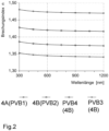
- Figure 2 shows a diagram of the refractive index n and wavelength for four PVB films with different reduced refractive index.
- PVB1 standard/reference /Refractive index at 500 nm approx. 1.48
- PVB 2 Refractive index at 500 nm approx. 1.43; ⁇ - 0.05
- PVB 3 Refractive index at 500 nm approx. 1.35; ⁇ -0.13
- PVB 4 is another PVB film with a refractive index at 500 nm of approx. 1.39, which is shown graphically.
- Figure 3 shows the color values a* and b* of the composite panes 100 from Table 1 with the different thermoplastic films PVB1 (standard/reference), PVB 2 (refractive index ⁇ -0.05) and PVB 3 (refractive index at 500 nm n ⁇ -0.13) in a color coordinate diagram a*b*, determined with the optical simulation program.
- the composite pane according to the invention has surprisingly good optical and aesthetic properties, whereby in particular undesirable color tones in the reflection of the composite pane can be minimized or even avoided.
- composite panes with an improved color impression in reflection are provided.
- the improved color effect and the resulting improved aesthetic optical impression can be achieved without negatively affecting other properties of the composite pane.
Landscapes
- Chemical & Material Sciences (AREA)
- Engineering & Computer Science (AREA)
- Organic Chemistry (AREA)
- Materials Engineering (AREA)
- Chemical Kinetics & Catalysis (AREA)
- Geochemistry & Mineralogy (AREA)
- General Chemical & Material Sciences (AREA)
- Life Sciences & Earth Sciences (AREA)
- Mechanical Engineering (AREA)
- Inorganic Chemistry (AREA)
- Metallurgy (AREA)
- Joining Of Glass To Other Materials (AREA)
- Laminated Bodies (AREA)
Description
- Die Erfindung betrifft eine Verbundscheibe mit verbesserten optischen Eigenschaften, insbesondere einer verbesserten Farbwirkung in der Reflexion, und ein Verfahren zur Herstellung einer solchen Verbundscheibe und deren Verwendung.
- Verbundglasscheiben bestehen aus zwei oder mehreren Einzelscheiben und werden mit einer oder mehreren Zwischenschichten bei Hitze und Druck fest miteinander verbunden. Die Zwischenschichten bestehen meist aus thermoplastischen Kunststoffen wie Polyvinylbutyral (PVB) oder Ethylenvinylacetat (EVA).
- An die Verglasung von Kraftfahrzeugen werden hohe Anforderungen gestellt. Hinsichtlich der Größe des Sichtbereichs und der strukturellen Stabilität der Scheiben gelten folgende gesetzlichen Vorschriften:
- ECE R 43: "Einheitliche Vorschriften für die Genehmigung des Sicherheitsglases und der Verbundglaswerkstoffe" sowie
- Technische Anforderungen an Fahrzeugteile bei der Bauartprüfung § 22 a StVZO, "Sicherheitsglas".
- Diese Vorschriften werden in der Regel durch Verbundglasscheiben erfüllt. Bei der Fertigung der Verbundscheiben wurden bisher thermoplastische Folien, insbesondere Polyvinylbutyral (PVB)-Folien eingesetzt, die einen Brechungsindex aufweisen, der möglichst nahe an dem der verwendeten Außenscheiben und Innenscheiben liegt. Üblicherweise liegt der Brechungsindex der bisher eingesetzten PVB Folien bei ca. 1,48 im sichtbaren Bereich, der gewöhnlich bei einem festen Wert, zum Beispiel bei 500 oder 550 nm angegeben wird. (D. C. Miller, Optical Engineering 50(1), 013003, 2011).
- Es ist bekannt, Windschutzscheiben mit transparenten, funktionellen Filmen, beispielsweise mit elektrisch leitfähigen Beschichtungen zu versehen. Diese Beschichtungen können beispielsweise als IR-reflektierende Beschichtungen wirken, um die Erwärmung des Fahrzeuginnenraums zu verringern und dadurch den thermischen Komfort zu verbessern. Die Beschichtungen können aber auch andere Funktionen erfüllen und beispielsweise als beheizbare Beschichtungen verwendet werden, indem sie mit einer Spannungsquelle verbunden werden, so dass ein Strom durch die Beschichtung fließt. Geeignete Beschichtungen enthalten beispielsweise leitfähige, metallische Schichten auf Basis von Silber. Da diese Schichten korrosionsanfällig sind, ist es üblich, sie auf die der Zwischenschicht zugewandten Oberfläche der Außenscheibe oder der Innenscheibe aufzubringen, so dass sie keinen Kontakt zur Atmosphäre haben. Sogenannte Low-E-Beschichtungen werden aber auch auf der Innenfläche der Innenscheibe aufgebracht. Silberhaltige transparente Beschichtungen sind beispielsweise bekannt aus
WO 03/024155 US2007/0082219 A1 ,US2007/0020465 A1 ,WO2013/104438 oderWO2013/14439 - In der
WO2019/206493 A1 ist eine Verbundscheibe mit einer elektrisch leitfähigen Beschichtung und einer Antireflexionsbeschichtung als Projektionsfläche für ein Head-Up-Display beschrieben. - Die
WO2012/052315 beschreibt eine transparente Verbundscheibe mit elektrisch beheizbarer Beschichtung, in der mindestens eine elektrisch beheizbare Beschichtung mindestens vier übereinander angeordnete funktionelle Schichten aufweist. Jede funktionelle Schicht umfasst dabei mindestens eine Schicht optisch hochbrechenden Materials mit einem Brechungsindex ≥ 2,1. Die funktionelle Schicht weist mehrere silberhaltige Schichten und dazwischen angeordnete Anpassungs- und Glättungsschichten auf. Die transparente Scheibe weist eine Gesamttransmission von > 70 % auf. - In der
DE 202019102388 U1 ist eine Verbundscheibe umfassend eine transparente elektrisch leitfähige Beschichtung beschrieben, die zusätzlich ein dielektrisches Übergitter aufweist. Das Übergitter ist bevorzugt aus alternierend angeordneten Schichten mit unterschiedlichen Brechungsindices gebildet und besteht dabei aus einer Vielzahl von Einzelschichten, wobei Schichten mit hohem Brechungsindex (bevorzugt größer 1,8 bei einer Wellenlänge von 550 nm) und Schichten mit niedrigem Brechungsindex (bevorzugt kleiner 1,8 bei einer Wellenlänge von 550 nm) alternierend übereinander angeordnet sind. Das Übergitter führt dabei zu einer Herabsetzung der Transmission im Spektralbereich von 400 nm bis 500 nm. Der Bereich mit dem Übergitter ist außerhalb des zentralen Sichtbereichs der Verbundscheibe angeordnet, so dass die Transmissionsverringerung keine negativen Auswirkungen für die Insassen des Fahrzeugs hat, insbesondere hinsichtlich der Gesamttransmission und eines etwaigen Farbstichs. - Bei dem Einsatz funktioneller Filme in Verbundscheiben muss der Fachmann bei der Gestaltung der Beschichtungen insbesondere im Fahrzeugbau verschiedenste Anforderungen beachten. Durch die typischerweise metallhaltigen leitfähigen Schichten der funktionellen Filme wird die Transmission im sichtbaren Spektralbereich herabgesetzt. Auch eine höhere Menge an leitfähigem Material für die einzelnen Schichten kann eine Verringerung der Transparenz der Verbundscheibe zur Folge haben. Da beispielsweise eine Windschutzscheibe strenge Anforderungen an die Mindesttransparenz erfüllen muss (mindestens 70% Transmission im sichtbaren Spektralbereich nach Regelung 43 der Wirtschaftskommission der Vereinten Nationen für Europa (ECE R 43)), sind der Menge an leitfähigem Material und der Anzahl an Schichten für die funktionellen Filme Grenzen gesetzt.
- Zusätzlich muss neben der Transparenz auch das Reflexionsspektrum der Verbundscheibe und weitere Randbedingungen berücksichtigt werden. Dies betrifft insbesondere die Farbwirkung der Verbundscheibe, denn wünschenswert sind in der Regel lediglich Scheiben mit einer grün-blauen Färbung, nicht jedoch einer gelben oder roten Färbung (bezogen auf die Reflexionsfarbe).
- Je höher die Anzahl der leitfähigen Schichten ist, desto besser ist gewöhnlich die Beschichtung hinsichtlich eines gewünschten Transmissionsgrads, der Farbgebung oder eines gewünschten Flächenwiderstands optimierbar. Die Beschichtungen als funktionelle Filme, insbesondere mit mehreren Edelmetallschichten sind jedoch zum einen vergleichsweise kostenintensiv und auch in ihrer Einstellbarkeit auf den gewünschten Farbeindruck in Kombination mit der notwendigen Transparenz limitiert. Es wird daher nach Alternativen gesucht die Farbwirkung einer Verbundscheibe, die mit einem oder mehreren funktionellen Filmen ausgestaltet werden soll, zu optimieren.
- Aufgabe der vorliegenden Erfindung ist daher die Bereitstellung einer transparenten Verbundscheibe mit mindestens einem funktionellen Film, wobei gleichzeitig mit der durch diesen Film bereitgestellten Funktion, zusätzlich ein verbessertes ästhetisches Erscheinungsbild, insbesondere möglichst frei von unerwünschten Farbtönen in der Reflexion der Verbundscheibe erzielt werden kann.
- Die Aufgabe der vorliegenden Erfindung wird erfindungsgemäß durch eine Verbundscheibe gemäß Anspruch 1 gelöst. Bevorzugte Ausführungen gehen aus den Unteransprüchen hervor.
- Erfindungsgemäß wird eine Verbundscheibe bereitgestellt, umfassend eine Außenscheibe und eine Innenscheibe, die über eine thermoplastische Zwischenschicht miteinander verbunden sind, wobei die Verbundscheibe mindestens einen funktionellen Film aufweist, der mindestens eine Metallschicht, insbesondere transparente Metallschicht, enthält, und die thermoplastische Zwischenschicht mit mindestens einer thermoplastischen Folie ausgebildet ist, die Brechungsindex-erniedrigende Mittel enthält und durch diese Brechungsindex-erniedrigenden Mittel der Brechungsindex der thermoplastischen Folie im optisch sichtbaren Bereich zwischen 380 nm - 780 nm um mindestens 0,05 (n Δ -0.05) erniedrigt ist.
- Mit anderen Worten wird erfindungsgemäß die Zwischenschicht der Verbundscheibe mindestens aus einer thermoplastischen Folie ausgebildet, deren Brechungsindex um mindestens 0,05 (n Δ -0.05) durch Brechungsindex-erniedrigenden Mittel gegenüber dem Brechungsindex n einer thermoplastischen Folie mit einer vergleichbaren Zusammensetzung, aber ohne die erfindungsgemäß eingesetzten Brechungsindex-erniedrigenden Mittel, erniedrigt ist. Gleichzeitig werden die weiteren, beispielsweise optischen oder mechanischen Eigenschaften der Folien und der resultierenden Verbundscheibe, wie zum Beispiel die geforderte Transparenz, Lichttransmission Bruchfestigkeit/Pummelwert oder Verarbeitbarkeit im Wesentlichen beibehalten. Die erfindungsgemäße Verbundscheibe weist hierdurch überraschend einen verbesserten Farbeindruck in der Reflexion auf ohne das weitere Eigenschaften der Verbundscheibe negativ beeinflusst werden.
- Die erfindungsgemäße Verbundscheibe umfasst eine Außenscheibe und eine Innenscheibe, die über eine thermoplastische Zwischenschicht miteinander verbunden sind. Die Verbundscheibe ist dafür vorgesehen, in einer Fensteröffnung, insbesondere der Fensteröffnung eines Fahrzeugs, den Innenraum gegenüber der äußeren Umgebung abzutrennen. Mit Innenscheibe wird im Sinne der Erfindung die dem Innenraum (insbesondere Fahrzeuginnenraum) zugewandte Scheibe der Verbundscheibe bezeichnet. Mit Außenscheibe wird die der äußeren Umgebung zugewandte Scheibe bezeichnet. Die Verbundscheibe ist bevorzugt eine Fahrzeug-Windschutzscheibe (insbesondere die Windschutzscheibe eines Kraftfahrzeugs, beispielsweise eines Personen- oder Lastkraftwagens), eine Seitenscheibe oder eine Dachscheibe.
- Die Verbundscheibe weist als Windschutzscheibe eine Oberkante und eine Unterkante auf sowie zwei dazwischen verlaufende Seitenkanten. Mit Oberkante wird diejenige Kante bezeichnet, welche dafür vorgesehen ist, in Einbaulage nach oben zu weisen. Mit Unterkante wird diejenige Kante bezeichnet, welche dafür vorgesehen ist, in Einbaulage nach unten zu weisen. Die Oberkante wird häufig auch als Dachkante und die Unterkante als Motorkante bezeichnet. Die Außenscheibe und die Innenscheibe weisen jeweils eine außenseitige und eine innenraumseitige Oberfläche auf und eine dazwischen verlaufende, umlaufende Seitenkante. Mit außenseitiger Oberfläche wird im Sinne der Erfindung diejenige Hauptfläche bezeichnet, welche dafür vorgesehen ist, in Einbaulage der äußeren Umgebung zugewandt zu sein. Mit innenraumseitiger Oberfläche wird im Sinne der Erfindung diejenige Hauptfläche bezeichnet, welche dafür vorgesehen ist, in Einbaulage dem Innenraum zugewandt zu sein. Die innenraumseitige Oberfläche der Außenscheibe und die außenseitige Oberfläche der Innenscheibe sind einander zugewandt und durch die thermoplastische Zwischenschicht miteinander verbunden.
- Die Oberflächen der Scheiben werden typischerweise wie folgt bezeichnet: Die Außenseite der Außenscheibe wird als Seite I bezeichnet. Die Innenseite der Außenscheibe wird als Seite II bezeichnet. Die Außenseite der Innenscheibe wird als Seite III bezeichnet. Die Innenseite der Innenscheibe wird als Seite IV bezeichnet.
- Die Außenscheibe und die Innenscheibe sind bevorzugt unabhängig voneinander aus Glas oder Kunststoff ausgebildet, bevorzugt Kalk-Natron-Glas, Alkalialuminosilikatglas, Polycarbonat oder Polymethylmethacrylat. In einer besonders bevorzugten Ausgestaltung bestehen die Außenscheibe und die Innenscheibe aus Glas.
- Die Außenscheibe und die Innenscheibe sind bevorzugt nicht mechanisch vorgespannt, sie können jedoch in weiteren Ausgestaltungen thermisch vorgespannt oder teilvorgespannt bzw. chemisch vorgespannt sein.
- Geeignete Glasscheiben umfassen Glasscheiben, die unter den Handelsnamen Planiclear® und Planilux® (jeweils Klarglas), VG 10, VG 20, VG 40 oder TSANx, TSA3+, TSA4+ von Saint-Gobain bekannt sind, wobei es sich bei den Gläsern der VG-Serie um graugefärbte Gläser und bei denen der TSA-Serie um grüngefärbte Gläser handelt.
- Die Außen- und/oder die Innenscheibe weist vorzugsweise unabhängig voneinander eine Dicke von 0,1 bis 4 mm, bevorzugt von 1 bis 4 mm, besonders bevorzugt von 1,6 mm bis etwa 2,1 mm auf.
- Die erfindungsgemäße Verbundscheibe weist außerdem mindestens einen funktionellen Film, bevorzugt einen transparenten funktionellen Film auf, der mindestens eine Metallschicht enthält. Dieser funktionelle Film enthält erfindungsgemäß also zumindest ein Metall oder eine Metalllegierung, beispielsweise Silber, Aluminium, Kupfer, Palladium, Platin oder Gold und ist bevorzugt auf Basis des Metalls oder der Metalllegierung ausgebildet, das heißt besteht im Wesentlichen aus dem Metall oder der Metalllegierung abgesehen von etwaigen Dotierungen oder Verunreinigungen.
- Der funktionelle Film ist beispielsweise auf der zur Zwischenschicht hingewandten, außenseitigen Oberfläche der Innenscheibe (Seite III) aufgebracht oder auf der zur Zwischenschicht hingewandten, innenraumseitigen Oberfläche der Außenscheibe (Seite II). Der funktionelle Film kann als Beschichtung alternativ innerhalb der Zwischenschicht angeordnet sein. Dazu kann der funktionelle Film auch auf einer Trägerfolie aufbracht sein, beispielsweise aus Polyethylenterephthalat (PET) mit einer Dicke von etwa 20 µm bis 100µm, beispielsweise 50 µm, welche zwischen zwei Lagen thermoplastischen Materials angeordnet ist, beispielsweise zwischen zwei Polymerfolien, beispielsweise PVB-Folien.
- Unter einem transparenten funktionellen Film wird eine Schicht oder ein Schichtsystem (Beschichtung) verstanden, die eine mittlere Transmission im sichtbaren Spektralbereich von mindestens 70%, bevorzugt mindestens 75% aufweist, die also die Durchsicht durch die Scheibe nicht wesentlich einschränkt und dabei Funktionen, wie Reflexion für ein HUD-Display, IR-strahlen Reflexion für eine Sonnenschutzbeschichtung bereitstellt oder ermöglicht. Der funktionelle Film kann auch als heizbare Beschichtung ausgestaltet sein, welche elektrisch kontaktiert ist und sich bei Stromdurchfluss erwärmt. Die Transmission im sichtbaren Spektralbereich wird bestimmt gemäß dem durch ECE-R 43, Anhang 3, § 9.1 festgelegten Verfahren zur Prüfung der Lichtdurchlässigkeit von Kraftfahrzeugscheiben.
- In einer weiteren Ausführungsform der erfindungsgemäßen Verbundscheibe umfasst der funktionelle Film als transparente Metallschicht mindestens eine Silberschicht, eine Aluminiumschicht, Kupferschicht, Palladiumschicht, Platinschicht oder eine Goldschicht. Erfindungsgemäß bevorzugt ist die mindestens eine Metallschicht eine Silberschicht. Als ein bevorzugtes Metall für die metallische Schicht hat sich Silber durchgesetzt, da es sowohl eine relativ neutrale Farbwirkung besitzt als auch beispielsweise bei der Verwendung als Sonnenschutzschicht die Infrarotstrahlung außerhalb des sichtbaren Bereichs der Sonnenstrahlung selektiv reflektiert.
- In einer anderen bevorzugten Ausgestaltung der Verbundscheibe weist der funktionelle Film zwei bis vier Metallschichten, bevorzugt 2, 3 oder 4 Silberschichten auf. Beispielsweise werden Schichtsysteme für Sonnenschutzschichten mit zwei Silberfunktionsschichten, aber auch drei oder vier Silberfunktionsschichten verwendet, da deren Wirkungsgrad, d.h. die Reflexion der Infrarotstrahlung außerhalb des sichtbaren Bereiches im Verhältnis zu Transmission der sichtbaren Strahlung, größer ist. Zudem ist auch die Einstellbarkeit bestimmter Eigenschaften, wie zum Beispiel die Farbwirkung mit größerer Schichtanzahl variabler.
- Die metallischen Schichten (Metallschichten), bevorzugt Silberschichten, werden in den funktionellen Filmen üblicherweise zwischen dielektrischen Schichten eingebettet. Mit anderen Worten sind die Metallschichten sandwichartig zwischen dielektrischen Schichten angeordnet.
- Die dielektrischen Schichten des funktionellen Films können geeignete, dem Fachmann bekannte Materialien enthalten, beispielsweise mindestens ein Metalloxid wie ZnO, ZnSnOx oder ein Metallnitrid, wie Si3N4, oder SiZrNx, oder NiCr. Die dielektrischen Materialien können auch Dotierungen, wie beispielsweise Aluminium aufweisen.
- Jede Metallschicht, beispielsweise Silberschicht, ist bevorzugt zwischen zwei dielektrischen Schichten angeordnet. Die Metallschichten und die dielektrischen Schichten sind dabei so angeordnet, dass beispielweise zwischen jeweils zwei benachbarten Silberschichten, zwischen denen keine weitere Silberschicht angeordnet ist, zumindest eine dielektrische Schicht, bevorzugt zwei oder mehr dielektrische Schichten, angeordnet ist und dass oberhalb der obersten Metallschicht, die in Einbaulage der Außenscheibe zugewandt ist, zumindest eine weitere dielektrische Schicht angeordnet ist und dass unterhalb der untersten Metallschicht, die der Innenscheibe zugewandt ist, zumindest eine weitere dielektrische Schicht angeordnet ist. Die dielektrischen Schichten weisen gemäß der Erfindung bevorzugt eine Dicke von 0,1 nm bis 100 nm, besonders bevorzugt von 0,2 nm bis 50 nm, beispielsweise zwischen 0,3 nm und 45 nm auf.
- Der erfindungsgemäße funktionelle Film kann beispielsweise als Beschichtung durch physikalische Gasphasenabscheidung (PVD) durch Kathodenzerstäubung ("Sputtern"), ganz besonders bevorzugt durch magnetfeldunterstütze Kathodenzerstäubung, beispielsweise auf die Innenscheibe, aufgebracht sein. Die funktionellen Filme werden bevorzugt als Beschichtungen vor der Lamination auf die Scheiben aufgebracht. Statt die Beschichtung auf eine Scheibenoberfläche aufzubringen, kann sie grundsätzlich auch auf einer Trägerfolie bereitgestellt werden, die in der Zwischenschicht angeordnet wird. Dies kann beispielsweise dadurch erzielt werden, dass in der Herstellung der Verbundscheibe der funktionelle Film zwischen mindestens zwei thermoplastischen Polymerfolien positioniert wird und dann die Polymerfolien durch die Einwirkung von Wärme, beispielsweise bei der Lamination miteinander verschmelzen und den IR-strahlen-reflektierenden Film durch das thermoplastische Material der Folien umflossen und gleichsam eingeschlossen wird. Hierdurch wird der funktionelle Film vor Umwelteinflüssen geschützt.
- In einer weiteren Ausführungsform der Verbundscheibe ist der Brechungsindex der thermoplastischen Folie durch die darin enthaltenen Brechungsindex-erniedrigenden Mittel im optisch sichtbaren Bereich (380 nm - 780 nm) zwischen 0,05 und 0,15 erniedrigt. Durch die Erniedrigung des Brechungsindex der thermoplastischen Folie, kann erfindungsgemäß ein verbessertes ästhetisches Erscheinungsbild der Verbundscheibe, insbesondere möglichst frei von unerwünschten Farbtönen in der Reflexion erzielt werden. Es hat sich gezeigt, dass mit stärkerer Verminderung des Brechungsindex der thermoplastischen Folie die Farbwirkung auch stärker in Richtung der gewünschten Farbneutralität, beziehungsweise in Richtung der Verminderung oder Vermeidung unerwünschter gelber und roter Farbtöne der Verbundscheibe beeinflusst werden kann.
- In einer bevorzugten Ausgestaltung der Erfindung sind die Brechungsindexerniedrigenden Mittel Nanopartikel, die im optisch sichtbaren Bereich einen Brechungsindex <1,4, bevorzugt < 1,3 bei einer Wellenlänge von 550 nm aufweisen. D.h. die angegebenen Werte für den Brechungsindex sind bei einer Wellenlänge von 550 nm gemessen. Der Brechungsindex kann beispielsweise mittels Ellipsometrie bestimmt werden. Ellipsometer sind kommerziell erhältlich.
- In einer weiter bevorzugten Ausgestaltung ist vorgesehen, dass die Brechungsindexerniedrigenden Mittel Metallfluorid Nanopartikel, insbesondere MgF2, CaF2, oder hohle SiO2 Nanopartikel sind, enthalten oder umfassen. Alkalimetallfluoride, mit einem Brechungsindex < 1,4 und Methoden zur Herstellung von Alkalimetallfluoriden, beispielsweise den genannten MgF2 und CaF2, sind beispielsweise in K. Scheurell, Inorganics 6,128, 2018 beschrieben. Die alternativ genannten hohlen SiO2 Nanopartikel werden beispielsweise in M. Gorsd, Procedia Materials Science 8, 567 - 576, 2015 und in T. Gao, Appl. Phys. A 110, 65-70, 2013 offenbart.
- In einer weiteren erfindungsgemäßen Ausführungsform sind in der thermoplastischen Folie mindestens 1 Gew.-% Brechungsindex-erniedrigende Mittel, insbesondere Nanopartikel, bezogen auf das Gesamtgewicht der Folie im Volumen der thermoplastischen Folie enthalten sind. Bevorzugt sind dabei 0,5-50 Gew-%; bevorzugt 1 bis 25 Gew. %, 1-10 Gew.-%, beispielsweise bis zu 5-Gew% Brechungsindex-erniedrigende Mittel, insbesondere Nanopartikel, bezogen auf das Gesamtgewicht der Folie im Volumen der thermoplastischen Folie enthalten.
- Die Brechungsindex-erniedrigenden Mittel sind erfindungsgemäß bevorzugt Nanopartikel mit einem mittleren Durchmesser von 5 nm bis 200 nm. Die Partikel weisen einen mittleren Partikeldurchmesser von 5 nm bis 200 nm, bevorzugt von < 150 nm, besonders bevorzugt < 100 nm, beispielsweise < 90 nm, <80 nm < 70 nm oder < 50 nm auf. Bevorzugt ist die Partikelgrößenverteilung möglichst homogen, das heißt die eingesetzten Partikel haben möglichst annähernd den gleichen Durchmesser. Im Sinne der Erfindung werden Partikel mit einem mittleren Durchmesser von kleiner oder gleich 500 nm als Nanopartikel bezeichnet. Nanopartikelgrößen können mittels dynamischer Lichtstreuung (DLS) gemessen werden.
- In einer weiteren Ausgestaltung der erfindungsgemäßen Verbundscheibe ist die thermoplastische Folie eine Polyvinylbutyral (PVB)-Folie, eine Ethylenvinylacetat (EVA)-Folie oder eine Polyurethan (PU)-Folie, bevorzugt eine PVB Folie. Mit anderen Worten sind die thermoplastischen Folien erfindungsgemäß als thermoplastische Polymerfolien ausgestaltet, die Polyvinylbutyral (PVB), Ethylenvinylacetat (EVA) oder Polyurethan, und/oder Gemische und/oder Copolymere hiervon enthalten. Besonders bevorzugt ist Polyvinylbutyral. Die thermoplastischen Folien sind bevorzugt auf Basis der genannten Materialien ausgebildet, können aber weitere Bestandteile, beispielsweise Weichmacher, enthalten. Die genannten Polymer-Folientypen sind, insbesondere für den Fahrzeugbereich gut geeignet.
- Vorteilhafterweise ist es möglich die Brechungsindex-erniedrigenden Mittel, insbesondere nanoskalige Partikel, in solche Polymerfolien einzubringen, ohne dass die weiteren, beispielsweise mechanischen, Eigenschaften der Folien negativ beeinflusst werden. Die thermoplastischen Folien können dabei Standardfolien mit einem erfindungsgemäß durch die Brechungsindex-erniedrigenden Mittel im optisch sichtbaren Bereich zwischen 380 nm - 780 nm um mindestens 0,05 erniedrigten Brechungsindex sein. Die thermoplastischen Folien können dabei klar, gefärbt/getönt (beispielsweise im Falle einer Dachscheibe), mit Farbband aber auch mit weiteren besonderen Eigenschaften oder Funktionen einzeln oder in Kombination ausgestaltet sein. Die thermoplastischen Folien können beispielsweise Keilfolien für die Funktion als Projektionsfläche für ein Head-Up-Display oder Akustikfolien sein.
- Bevorzugt weist die thermoplastische Folie der erfindungsgemäßen Verbundscheibe eine Dicke von mindestens 0.1 mm bis maximal 2 mm, bevorzugt 0.2 mm bis 1 mm, besonders bevorzugt 0.3 mm bis 0.8 mm auf. Polymerfolien der Zwischenschicht, insbesondere die PVB-Folien, haben beispielsweise eine Dicke von 0,38 mm, 0,76 mm oder 0,81 mm. Über die Dicke der Folien können weitere Eigenschaften der Verbundglasscheibe beeinflusst werden. So bewirken etwa dickere PVB-Folien eine verbesserte Schalldämpfung, insbesondere wenn sie einen akustisch wirksamen Kern enthalten, einen erhöhten Einbruchswiderstand der Verbundglasscheibe und auch einen erhöhten Schutz gegen ultraviolette Strahlung (UV- Schutz).
- In einer anderen bevorzugten Ausführungsform der Verbundscheibe ist vorgesehen, dass die Zwischenschicht aus zwei oder mehr thermoplastischen Folien ausgebildet ist, die einen voneinander verschiedenen Brechungsindex aufweisen. Die optischen Eigenschaften, insbesondere die Farbwirkung in der Reflexion von der Außen- und der Innenseite kann hierdurch nochmals vorteilhaft beeinflusst und auf die gewünschten Werte für die Verbundscheibe optimiert werden.
- Weiterhin umfasst die Erfindung ein Verfahren zur Herstellung einer erfindungsgemäßen Verbundscheibe wie sie in verschiedenen Ausgestaltungen vorstehend beschrieben wurde, umfassend die Schritte:
- S1: Bereitstellen einer thermoplastischen Folie enthaltend Brechungsindex-erniedrigende Mittel;
- S2: Bereitstellen eines funktionellen Films auf der Außenscheibe, der Innenscheibe, auf der thermoplastischen Folie und/oder auf einer Trägerfolie;
- S3: Bilden einer Stapelfolge aus Außenscheibe, Innenscheibe und der thermoplastischen Folie sowie ggf. der Trägerfolie;
- S4: Verbinden der Stapelfolge unter Einwirkung von Druck, Wärme und/oder Vakuum.
- Die thermoplastischen Folien können in Schritt 1 durch an sich bekannte Verfahren hergestellt werden. In einer bevorzugten Ausgestaltung werden die Folien mit die Brechungsindex-erniedrigenden Nanopartikel, die im optisch sichtbaren Bereich einen Brechungsindex <1,4, bevorzugt < 1,3 aufweisen gefertigt. Mit anderen Worten sind die Nanopartikel im Volumen der Folien dispergiert. Die Fertigung der Folien mit den darin dispergierten Nanopartikeln kann beispielsweise in analoger Weise zu den in
JP 2002326846 A US2003/0054160 A1 oder derEP1227070 B1 beschriebenen Verfahren erfolgen. - Vorteilhafterweise ist es möglich die Brechungsindex-erniedrigenden Mittel, insbesondere nanoskalige Partikel, in solche Polymerfolien einzubringen, ohne dass die weiteren, beispielsweise mechanischen, Eigenschaften der Folien negativ beeinflusst werden. Die thermoplastischen Folien können dabei Standardfolien, beispielsweise PVB-Folien ergänzt um die erfindungsgemäßen Brechungsindex-erniedrigenden Mittel sein, die im optisch sichtbaren Bereich (380 nm - 780 nm) den Brechungsindex der Folie um mindestens 0,05 erniedrigen. Die thermoplastischen Folien können dabei klar, gefärbt/getönt, mit Farbband aber auch mit weiteren besonderen Eigenschaften oder Funktionen einzeln oder in Kombination ausgestaltet sein. Die thermoplastischen Folien können beispielsweise Keilfolien für die Funktion als Projektionsfläche für ein Head-Up-Display oder Akustikfolien sein.
- In einer weiter bevorzugten Ausgestaltung ist vorgesehen, dass die Brechungsindexerniedrigenden Mittel Metallfluorid Nanopartikel, insbesondere MgF2, CaF2, oder hohle SiO2 Nanopartikel sind, enthalten oder umfassen.
- In Schritt S2 kann der funktionelle Film beispielsweise durch physikalische Gasphasenabscheidung (PVD), durch Kathodenzerstäubung (Sputtern) oder durch magnetfeldunterstütze Kathodenzerstäubung auf die Innenscheibe oder die Außenscheibe aufgebracht werden. Bevorzugt werden die funktionellen Filme auf die Innenseite II der Außenscheibe oder die Außenseite III der Innenscheibe aufgebracht Die Beschichtungen werden bevorzugt vor der Lamination auf die Scheiben aufgebracht.
- Bevorzugt werden mindestens 80% der Scheibenfläche mit dem funktionellen Film als Beschichtung versehen. Insbesondere ist die Verbundscheibe vollflächig mit der Beschichtung versehen mit Ausnahme eines umlaufenden Randbereichs und optional lokaler Bereich, die als Kommunikations-, Sensor- oder Kamerafenster die Transmission von elektromagnetischer Strahlung durch die Verbundscheibe gewährleisten sollen und daher nicht mit der Beschichtung versehen werden. Der umlaufende unbeschichtete Randbereich kann beispielsweise eine Breite von bis zu 20 cm aufweisen. Dies verhindert den direkten Kontakt der Beschichtung zur umgebenden Atmosphäre, so dass die Beschichtung im Innern der Verbundscheibe vorteilhaft Korrosion und Beschädigung geschützt ist.
- Statt die funktionellen Filme als Beschichtung auf eine Scheibenoberfläche aufzubringen, kann sie grundsätzlich auch auf einer Trägerfolie, beispielsweise aus Polyethylenterephthalat (PET) bereitgestellt werden, die in der Zwischenschicht angeordnet wird. Dies kann beispielsweise dadurch erzielt werden, dass in Schritt S3 der Verbundscheibe der funktionelle Film zwischen mindestens zwei thermoplastischen Polymerfolien positioniert wird.
- In Schritt S3 werden die Außenscheibe, Innenscheibe und die thermoplastische Folie sowie ggf. die Trägerfolie in üblicher Weise flächig übereinander angeordnet.
- Soll die Verbundscheibe gebogen sein, so werden die Außenscheibe und die Innenscheibe bevorzugt vor dem Schritt S4 und bevorzugt nach etwaiger Beschichtungsprozesse in Schritt S2 einem Biegeprozess unterzogen. Bevorzugt werden die Außenscheibe und die Innenscheibe gemeinsam (d.h. zeitgleich und durch dasselbe Werkzeug) kongruent gebogen, weil dadurch die Form der Scheiben für die später erfolgende Laminierung optimal aufeinander abgestimmt sind. Typische Temperaturen für Glasbiegeprozesse betragen beispielsweise 500°C bis 700°C.
- Das Verbinden der Außenscheibe und der Innenscheibe über die thermoplastische Zwischenschicht aus der Stapelfolge zur Verbundscheibe in Schritt S4 erfolgt bevorzugt durch Laminieren unter Einwirkung von Hitze, Vakuum und/oder Druck. Es können an sich bekannte Verfahren zur Herstellung einer Verbundscheibe verwendet werden. Beim Laminieren fließt das erhitzte, fließfähige thermoplastische Material um den funktionellen Film herum, so dass ein stabiler Verbund hergestellt wird und die Sonnenschutzbeschichtung in die Zwischenschicht eingekapselt und vor Beschädigung und Umwelteinflüssen geschützt wird.
- Es können beispielsweise sogenannte Autoklavverfahren bei einem erhöhten Druck von etwa 10 bar bis 15 bar und Temperaturen von 130 °C bis 145 °C über etwa 2 Stunden durchgeführt werden. An sich bekannte Vakuumsack- oder Vakuumringverfahren arbeiten beispielsweise bei etwa 200 mbar und 80°C bis 110 °C. Die Außenscheibe, die thermoplastische Zwischenschicht und die Innenscheibe können auch in einem Kalander zwischen mindestens einem Walzenpaar zu einer Scheibe verpresst werden. Anlagen dieser Art sind zur Herstellung von Scheiben bekannt und verfügen normalerweise über mindestens einen Heiztunnel vor einem Presswerk. Die Temperatur während des Pressvorgangs beträgt beispielsweise von 40 °C bis 150 °C. Kombinationen von Kalander- und Autoklavverfahren haben sich in der Praxis besonders bewährt. Alternativ können Vakuumlaminatoren eingesetzt werden. Diese bestehen aus einer oder mehreren beheizbaren und evakuierbaren Kammern, in denen die Scheiben innerhalb von beispielsweise etwa 60 Minuten bei verminderten Drücken von 0,01 mbar bis 800 mbar und Temperaturen von 80°C bis 170°C laminiert werden.
- In einer bevorzugten Ausgestaltung des Verfahrens ist vorgesehen, dass die in Schritt S1 bereitgestellte thermoplastische Folie (4B) mit Metallfluorid-Nanopartikeln, insbesondere MgF2, CaF2, oder hohlen SiO2 Nanopartikeln als Brechungsindexerniedrigenden Mitteln ausgebildet ist. Nanopartikel lassen sich in die Folien mit üblichen Verfahren in die Folien integrieren ohne das andere Eigenschaften nachteilig beeinflusst werden.
- In einer anderen Ausgestaltung des Verfahrens ist vorgesehen, dass in Schritt S1 zwei oder mehr thermoplastische Folien (4B, 4, 4A) eingesetzt werden, die einen unterschiedlichen Brechungsindex aufweisen. Mit anderen Worten wird hiermit eine Zwischenschicht aus zwei oder mehr thermoplastischen Folien ausgebildet, die einen voneinander verschiedenen Brechungsindex aufweisen. Die optischen Eigenschaften, insbesondere die Farbwirkung in der Reflexion von der Außen- und der Innenseite der Verbundscheibe kann hierdurch nochmals vorteilhaft beeinflusst und auf die gewünschten Werte für die Verbundscheibe optimiert werden.
- Die Erfindung umfasst weiterhin die Verwendung der erfindungsgemäßen Verbundscheibe in Fortbewegungsmitteln für den Verkehr auf dem Lande, in der Luft oder zu Wasser, insbesondere in Kraftfahrzeugen beispielsweise als Windschutzscheibe, Heckscheibe, Seitenscheibe und/oder Dachscheibe.
- Alle genannten Normen beziehen sich auf deren zum Anmeldetag gültige Fassung.
- Die verschiedenen Ausgestaltungen der Erfindung können einzeln oder in beliebigen Kombinationen realisiert sein. Insbesondere sind die vorstehend genannten und nachstehend zu erläuternden Merkmale nicht nur in den angegebenen Kombinationen, sondern auch in anderen Kombinationen oder in Alleinstellung einsetzbar, ohne den Rahmen der Erfindung zu verlassen. Es sei denn Ausführungsbeispiele und/oder ihre Merkmale sind explizit nur als Alternativen genannt oder schließen sich aus.
- Nachfolgend wird die Erfindung eingehender unter Bezugnahme auf die Beispiele und Figuren dargestellt. Dabei ist anzumerken, dass unterschiedliche Aspekte beschrieben werden, die jeweils einzeln oder in Kombination zum Einsatz kommen können. D.h. jeglicher Aspekt kann mit unterschiedlichen Ausführungsformen der Erfindung verwendet werden, soweit nicht explizit als reine Alternative dargestellt.
- Die Zeichnungen sind vereinfachte, schematische Darstellungen und nicht maßstabsgetreu. Die Zeichnungen schränken die Erfindung in keiner Weise ein.
-
Tabelle 1 ClimaCoat® mit 4 Silberschichten Laminat Standard PVB1 Brechungsindex 1,48 PVB2 Mit niedrigem Brechungsindex (Δ -0.05) PVB3 mit ultraniedrigem Brechungsindex (Δ-0.13) TL (A) 71.7% 71.6% 71.4% a* 8° -7.6 -7.7 -7.7 b* 8° -10.7 -9.4 -7.8 a* 60° +0.9 -0.2 -1.4 b* 60° -5.3 -4.3 -3.2 - Die Tabelle 1 zeigt vergleichend die integralen Werte für eine Verbundscheibe mit einem Flächenwiderstand von ca. 0,7 Ohm, mit einer Standard PVB, die unter dem Handelsnamen ClimaCoat® von Saint Gobain erhältlich ist, zu den Werten von gleich aufgebauten und vergleichbaren Verbundscheiben-Laminaten jedoch einmal mit einer PVB mit niedrigem Brechungsindex (gegenüber der Standard PVB um 0,05 erniedrigt) und einer PVB mit einem ultra niedrigen Brechungsindex (gegenüber der Standard PVB um 0,13 erniedrigt). Die Reflexionswerte werden durch Simulationen mit einem gebräuchlichen optischen Simulationsprogramm bestimmt.
- Die angegebenen Farbwerte beschreiben die Reflexionsfarbe der jeweiligen Verbundscheibe und sind auf den L* a* b*-Farbraum (auch: Lab-Farbraum) bezogen, welcher in der EN ISO 11664-4 "Colorimetry -- Part 4: CIE 1976 L* a* b* Colour space" und der neueren DIN EN 410 genormt ist. Die angegebenen Farbwerte a* , b* beziehen sich zumindest auf die außenseitige Reflexionsfarbe unter Bestrahlung mit der Lichtquelle D65 und Einstrahlwinkeln von 8° und 60° (Winkel zur Flächennormalen), gemessen bei Bestrahlung der Außenscheibe mit Strahlung gemischter Polarisation (50% s, 50% p) und Messbedingungen, die in den genannten Normen mit D65/10 spezifiziert sind.
- Es zeigt sich das die Außenseitige Reflexion bei 8° mit der zunehmenden Erniedrigung des Brechungsindex weniger blau und bei 60° weniger rot ist. Der Unterschied zu den Farbwerten der Verbundscheibe mit der Standard-PVB-Folie beträgt jeweils mehr als einen Punkt und ist daher als eine signifikante Verbesserung zu werten. Die zu erkennende Tendenz in Richtung einer Farbneutralität mit der Erniedrigung des Brechungsindex der PVB-Folie lässt die Annahme zu, dass eine weitere Senkung des Brechungsindex der eingesetzten PVB-Folie könnte diesen Effekt der verbesserten Farbwirkung in der Reflexion der Verbundscheibe noch verstärken.
Tabelle 1-1 Schichtaufbau für die Verbundscheiben aus Tabelle 1 mit 4 Metallschichten Verbundscheibe mit funktionellem Film mit 4 Silberschichten Schichtdicke Außenscheibe1 Klare Glasscheibe Planiclear® PLC 2,1 mm Thermoplastische Folie 4 Standard PVB1 4A (Stand der Technik) oder 0.737 mm PVB2 mit erniedrigtem Brechungsindex n(Δ -0.05) 4B(erfindungsgemäß) oder Thermoplastische Folie 4 PVB3 mit erniedrigtem Brechungsindex n(Δ -0.13) 4B(erfindungsgemäß) Si3N4 15.8 nm SiZrNx 8.1 nm Funktioneller Film 5 ZnO 13 nm NiCr 0,2 nm Ag [Metallschicht 6] 10.9 nm ZnO 12.0 nm ZnSnOx 10.0 nm SiZrNx 21,1 nm Si3N4 20.9 nm ZnO 16.0 nm NiCr 0,2 nm Ag [Metallschicht 6] 14.2 nm ZnO 14,0 nm ZnSnOx 11.0 nm SiZrNx 18.4 nm Si3N4 17.2 nm ZnO 15.0 nm NiCr 0,3 nm Ag [Metallschicht 6] 13,5 nm ZnO 16.0 nm ZnSnOx 10.0 nm SiZrNx 35.5 nm ZnO 16 nm NiCr 0,2 nm Ag [Metallschicht 6] 11.5 nm ZnO 11.0 nm ZnSnOx 8.0 nm SiZrNx 13.7 nm Innenscheibe 2 Klare Glasscheibe Planiclear® PLC 1,6 mm - In Tabelle 1-1 sind die Schichtaufbauten für die drei Verbundscheiben mit vier Silberschichten wiedergegeben, deren Werte durch Simulation ermittelt wurden, wobei jeweils die Schichtabfolge und die Schichtdicken beibehalten werden und der Unterschied nur im verschiedenen Brechungsindex der jeweils für die Verbundscheibe eingesetzten PVB1 (Standard/Referenz n bei 500 nm 1,48) und der PVB2 (n (Δ -0.05) und der PVB3 (n (Δ -0.13) liegt.
Tabelle 2 ClimaCoat® mit 3 Silberschichten Laminat Standard PVB1 PVB2. Mit niedrigem Brechungsindex (n Δ -0.05) TL (A) 72.4% 72.7% a* 8° -2.5 -1,3 b* 8° -2.9 -3,1 a* 60° +0.1 -0.2 b* 60° 5.0 5.0 - Die Tabelle 2 zeigt vergleichend die integralen Werte für eine Verbundscheibe mit einem Flächenwiderstand von ca. 0,9 Ohm, mit einer Standard PVB, die unter dem Handelsnamen ClimaCoat® von Saint Gobain erhältlich ist, zu gleich aufgebauten und vergleichbaren Verbundscheiben-Laminaten jedoch einmal mit einer PVB mit niedrigem Brechungsindex (gegenüber der Standard PVB um 0,05 erniedrigt). Bei der Simulation zeigen sich die gleichen Tendenzen, in den Reflexionswerten wie bei den in Tabelle 1 wiedergegebenen Simulationsmessungen, jedoch weniger stark ausgeprägt.
Tabelle 2-1 Schichtaufbau für die Verbundscheiben aus Tabelle 2 Verbundscheibe mit funktionellem Film mit 3 Silberschichten Schichtdicke Außenscheibe1 Klare Glasscheibe Planiclear® PLC 2,1 mm Standard PVB1 4A (Stand der Technik) oder Thermoplastische Folie 4 PVB2 mit erniedrigtem Brechungsindex n (Δ -0.05) 4B(erfindungsgemäß) 0.76 mm Funktioneller Film 5 SiZrNx 9.6 nm Si3N4 9.9 nm ZnO 13 nm NiCr 0.2 nm Ag [Metallschicht 6] 9.0 nm ZnO 14.0 nm ZnSnOx 7.0 nm SiZrNx 21.5 nm Funktioneller Film 5 Si3N4 25.5 nm ZnO 10.0 nm NiCr 0.3 nm Ag [Metallschicht 6] 9.5 nm ZnO 9,0 nm ZnSnOx 8.0 nm SiZrNx 42.1 nm ZnO 13 nm NiCr 0.2 nm Ag [Metallschicht 6] 9.5 nm ZnO 13 nm ZnSnOx 7.0 nm SiZrNx 10.9 nm Innenscheibe 2 Klare Glasscheibe Planiclear® PLC 1.6 mm - In Tabelle 2-1 sind die Schichtaufbauten für die zwei Verbundscheiben mit drei Silberschichten wiedergegeben, wobei die Schichtabfolge und die Schichtdicken beibehalten werden und der Unterschied nur im verschiedenen Brechungsindex der jeweils für die Verbundscheibe eingesetzten PVB1 (Standard/Referenz n bei 500 nm 1,48) und der PVB2 (n (Δ -0.05) liegt.
Tabelle 3 Schichtaufbau des HUD-Verbundscheiben Laminats HUD Verbundscheiben-Laminat Standard PVB1 Brechungsindex n 1,48 bei 500 nm PVB2 mit niedrigem Brechungsindexindex (Δ -0.05) TL (A) 71.9% 71.5% a*t -1,5 -1.3 b*t 0.6 0.9 RL(A) 22.9 23.4 a* 8° -0.5 -1.1 b* 8° 1.8 1.0 RL(A) 60° 28.0 28.1 a* 60° -0.6 -1.1 b* 60° 1.1 0.5 RL(A) p-pol 20.1 20.1 a* p-pol 0.6 0.4 b* p-pol 1.1 0.3 TTS 59.7 59.7 Polarisationsverhältnis 1.405 1.412 - Die Tabelle 3 zeigt vergleichend die integralen Werte für eine HUD-kompatible Verbundscheibe (HUD-Verbundscheibe) mit einer Silberschicht (mit einer Standard PVB (PVB1), zu einem gleich aufgebauten und vergleichbaren Verbundscheiben-Laminat jedoch mit einer PVB mit niedrigem Brechungsindex n. PVB2 gegenüber PVB1 ist n um 0,05 erniedrigt (n Δ -0.05).
- Der Schichtaufbau für die Verbundscheibenlaminate der mit der Simulation mit einem optischen Simulationsprogramm untersucht wurde, ist in
Figur 1 und der dazugehörigen Beschreibung wiedergegeben. - Auch in dieser Simulation zeigt sich bei nahezu gleichbleibender Lichttransmission TL(A) und einem identischen TTS Wert (total transmission of solar energy) ein signifikanter Effekt in der Farbwirkung der Verbundscheibe in der Reflexion. Die Reflexionsfarbe bei 8° und 60° wird durch die PVB-Folie mit dem erniedrigten Brechungsindex in den grün-Bereich verschoben. Auch die HUD p-pol Reflexionsfarbe wird mit der PVB mit erniedrigten Brechungsindex farbneutraler. Dies bedeutet, dass bei einer HUD-Projektion eine störende Farbverschiebung vermindert oder vermieden werden kann. Je näher die Farbwerte a* und b* an Null herankommen, desto farbneutraler ist die Farbwirkung in der Reflexion. Überraschend wurde bei dem Vergleich der beiden HUD-Verbundscheiben-Laminate mit dem Einsatz der PVB mit dem erniedrigten Brechungsindex zusätzlich eine um 0.007 erhöhtes Polarisationsverhältnis (p-Polarisation / s-Polarisation) festgestellt. Dieses Verhältnis soll für die Funktionalität von in der Windschutzscheibe integrierten Kamerasystemen möglichst hoch sein.
- Die in den Tabellen 1 bis 3 wiedergegebenen Werte sind durch Simulation mit einem optischen Simulationsprogramm erhalten worden.
- Es bedeuten:
- RL(A) sichtbare externe Reflexion [%] Ein außenseitiges Reflexionsvermögen beschreibt dabei den reflektierten Anteil der von der äußeren Umgebung einfallenden sichtbaren Strahlung.
- TL(A) sichtbare Lichttransmission [%] der Verbundscheiben
- TTS totale transmittierte Wärmestrahlung [%]
- RL(A) 60° sichtbare Reflexion bei einem Betrachtungswinkel von 60[%]
- RL(A) p-pol sichtbare p-pol Reflexion [%]
- L*, a*, b* Farbkoordinaten (Farbraum CIE, International Commision on Illumination)
- Es zeigen:
-
Figur 1 einen schematischen Querschnitt durch einen Schichtaufbau für eine erfindungsgemäße Verbundscheibe am Beispiel eines HUD-kompatiblen Verbundscheiben-Laminats (HUD-Verbundscheibe /HUD-Laminat); -
Figur 2 ein Diagramm des Brechungsindex n und Wellenlänge für PVB-Folien mit unterschiedlich erniedrigtem Brechungsindex -
Figur 3 die Farbwerte a* b* der Verbundscheiben aus Tabelle 1 mit den thermoplastischen Folien PVB1, PVB 2 und PVB 3 in einem Farbdiagramm. -
Figur 1 zeigt einen schematischen Querschnitt durch einen Schichtaufbau 10 für eine erfindungsgemäße Verbundscheibe 100 am Beispiel eines HUD-Laminats, wie es mit dem optischen Simulationsprogramm untersucht wurde. Die Werte für die vergleichenden optisch simulierten Messungen, einmal für eine Verbundscheibe 100 mit einer klaren Standard-PVB Folie 4A, (Stand der Technik) und einmal mit einer klaren PVB Folie 4B mit erfindungsgemäß erniedrigtem Brechungsindex n sind in der Tabelle 3 wiedergegeben. Der Schichtaufbau 10 für die Verbundscheibe 100 umfasst eine Außenscheibe 1, eine Innenscheibe 2 und eine Zwischenschicht 3. Die Innenscheibe 2 und die Außenscheibe 1 sind im Beispiel, welches der optischen Simulation (Tabelle 3) zugrunde gelegt wurde, 2,1 mm Dicke klare Glasscheiben, die beispielsweise unter dem Handelsnamen Planiclear® erhältlich sind Die Zwischenschicht, 3 umfasst eine thermoplastische Folie 4 (4A Stand der Technik/ 4B erfindungsgemäß mit erniedrigtem Brechungsindex n) in den vergleichenden Beispielen aus Tabelle 3 jeweils eine PVB-Folie 4A (PVB1 Standard/Stand der Technik) und PVB-Folie 4B (PVB2/ mit erniedrigtem Brechungsindex) mit einer Dicke von 0,76 mm. Auf der Außenseite III der Innenscheibe 2 zur thermoplastischen Folie 4 (4A/4B) hin gerichtet ist in der Zwischenschicht 3 ein mehrschichtiger, funktioneller Film 5 mit einer transparenten Silberschicht 6 angeordnet. Der funktionelle Film 5 der Beispiel-Verbundscheiben 100, umfasst eine Silberschicht 6 mit einer Dicke von 12,5 nm und weitere dielektrische Schichten (5a, 5b, 5c, 5d,5e, 5f). Der Schichtaufbau für die optischen Simulationen aus Tabelle 3 ist in der Tabelle 4 detailliert wiedergegeben. Der funktionelle Film 5 kann beispielsweise durch übliche Verfahren, wie Sputtern auf die Innenscheibe aufgebracht sein. Es hat sich gezeigt, dass die erfindungsgemäßen Verbundscheiben 100 bei nahezu gleichen Transmissionswerten TL(A) einen signifikanten, positiven Effekt in der Farbwirkung in der Reflexion zeigen. Die Reflexionsfarbe der Verbundscheibe 100 wird durch die erfindungsgemäße PVB-Folie 4B (Tabelle 3, PVB2) mit dem erniedrigten Brechungsindex n in den grün-Bereich verschoben. Auch die HUD p-pol Reflexionsfarbe wird mit der PVB-Folie 4B (PVB2) mit erniedrigten Brechungsindex n farbneutraler. Dies bedeutet, dass bei der Verbundscheibe 100, die erfindungsgemäß mit der PVB Folie 4B mit dem erniedrigten Brechungsindex n gefertigt wurde, bei einer HUD-Projektion eine störende Farbverschiebung im Vergleich zum Stand der Technik (Einsatz der Standard PVB-Folie 4A) vermindert oder vermieden werden kann. Je näher die Farbwerte a* und b* an Null herankommen, desto farbneutraler ist die Farbwirkung in der Reflexion. Überraschend wurde bei dem Vergleich der beiden HUD-Verbundscheiben-Laminate 100 mit dem Einsatz der PVB2 4B mit dem erniedrigten Brechungsindex zusätzlich ein um 0.007 erhöhtes Polarisationsverhältnis (p-Polarisation) festgestellt.Tabelle 4 Aufbau einer Verbundscheibe 100 am Beispiel einer HUD-Verbundscheibe mit einer Silberschicht vergleichend mit einer PVB1 (4A) und einer PVB2 (4B) als thermoplastische Folie 4 (4A/4B) HUD-Verbundscheibe Schichtdicke Außenscheibe1 Klare Glasscheibe Planiclear® PLC 2.1 mm Thermoplastische Folie 4 Standard PVB1 4A (Stand der Technik) oder 0.76 mm PVB2 mit erniedrigtem Brechungsindex 4B (erfindungsgemäß) Funktioneller Film 5 Si3N4 50 nm SiZrNx 10 nm ZnO 10 nm NiCr 0.3 nm Ag [Metallschicht 6] 12.5 nm ZnO 10.0 nm SiZrNx 10.0 nm Si3N4 10.0 nm Innenscheibe 2 Klare Glasscheibe Planiclear® PLC 2.1 mm -
Figur 2 zeigt in einem Diagramm des Brechungsindex n und Wellenlänge für vier PVB-Folien mit unterschiedlich erniedrigtem Brechungsindex. Mit PVB1 (Standard/Referenz /Brechungsindex bei 500nm ca 1,48), PVB 2 (Brechungsindex bei 500nm ca. 1,43; Δ - 0.05) und PVB 3 (Brechungsindex bei 500 nm ca. 1,35; Δ -0.13) wurden die Simulationen durchgeführt, die die in den Tabellen 1 bis 3 wiedergegebenen Werte ergaben. Mit PVB 4 ist eine weitere PVB Folie mit einem Brechungsindex bei 500 nm, von ca.1,39 graphisch dargestellt. -
Figur 3 zeigt die mit dem optischen Simulationsprogramm ermittelten Farbwerte a* und b* der Verbundscheiben 100 aus Tabelle 1 mit den unterschiedlichen thermoplastischen Folien PVB1 (Standard/Referenz), PVB 2 (Brechungsindex Δ -0.05) und PVB 3 (Brechungsindex bei 500 nm n Δ -0.13) in einem Farbkoordinatendiagramm a*b*. - Es zeigt sich das die Außenseitige Reflexion bei 8°mit der zunehmenden Erniedrigung des Brechungsindex weniger blau und bei 60° weniger rot ist. Die mit den Pfeilen X (Werte Reflexion bei 8°) und Y (Werte Reflexion bei 60°) im Diagramm dargestellte Tendenz in Richtung einer Farbneutralität mit der Erniedrigung des Brechungsindex der PVB-Folie 4 lässt die Annahme zu, dass eine weitere Senkung des Brechungsindex n der eingesetzten PVB-Folie diesen Effekt der verbesserten Farbwirkung in der Reflexion der Verbundscheibe 100 noch verstärken könnte.
- Die erfindungsgemäße Verbundscheibe weist überraschend gute optische und ästhetische Eigenschaften auf, wobei insbesondere unerwünschte Farbtöne in der Reflexion der Verbundscheibe minimiert oder sogar vermieden werden können.
- Dies ist erfindungsgemäß möglich ohne das weitere Eigenschaften der Verbundscheibe negativ beeinflusst werden.
- Erfindungsgemäß werden also Verbundscheiben mit einem verbesserten Farbeindruck in der Reflexion bereitgestellt. Vorteilhafterweise kann die verbesserte Farbwirkung und der dadurch verbesserte ästhetische optische Eindruck erzielt werden, ohne dass weitere Eigenschaften der Verbundscheibe negativ beeinflusst werden.
-
- 100
- Verbundscheibe
- 10
- Schichtaufbau
- 1
- Außenscheibe
- 2
- Innenscheibe
- 3
- Zwischenschicht
- 4
- thermoplastische Folie
- 4A
- Standard-PVB Folie (Stand der Technik)
- 4B
- PVB-Folie 4B (PVB2/ mit erfindungsgemäß erniedrigtem Brechungsindex).
- 5
- funktioneller Film
- 5a, 5b, 5c, 5d, 5e, 5f
- dielektrische Schichten
- 6
- Metallschicht
- I
- Außenfläche der Außenscheibe 1
- II
- Innenfläche der Außenscheibe 1
- III
- Außenfläche der Innenscheibe 2
- IV
- Innenfläche der Innenscheibe 2
- X
- Tendenz Werte der Reflexion bei 8° mit abnehmendem Brechungsindex der PVB
- Y
- Tendenz Werte Reflexion bei 60° mit abnehmendem Brechungsindex der PVB
Claims (15)
- Verbundscheibe (100) umfassend eine Außenscheibe (1) und eine Innenscheibe (2), die über eine thermoplastische Zwischenschicht (3) miteinander verbunden sind, dadurch gekennzeichnet, dass die Verbundscheibe (100) mindestens einen funktionellen Film (5) aufweist, der mindestens eine Metallschicht (6) enthält, und die thermoplastische Zwischenschicht (3) mit mindestens einer thermoplastischen Folie (4B) ausgebildet ist, die Brechungsindex-erniedrigende Mittel enthält und durch diese Brechungsindex-erniedrigenden Mittel der Brechungsindex der thermoplastischen Folie (4B) im optisch sichtbaren Bereich zwischen 380 nm - 780 nm um mindestens 0,05 erniedrigt ist.
- Verbundscheibe nach Anspruch 1 dadurch gekennzeichnet, dass der funktionelle Film (5) als Metallschicht (6) mindestens eine Silberschicht Aluminium-, Kupfer-, Palladium-, Platin-, oder eine Goldschicht umfasst.
- Verbundscheibe nach Anspruch 1 oder 2 dadurch gekennzeichnet, dass der funktionelle Film (5) zwei bis vier Metallschichten (6), bevorzugt 2, 3 oder 4 Silberschichten aufweist.
- Verbundscheibe nach einem der Ansprüche 1 bis 3 dadurch gekennzeichnet, dass der funktionelle Film (5) mindestens zwei dielektrische Schichten (5a, 5b, 5c, 5d, 5d, 5e) umfasst, die die Metallschichten (6) sandwichartig einbetten.
- Verbundscheibe nach einem der Ansprüche 1 bis 4 dadurch gekennzeichnet, dass der Brechungsindex der thermoplastischen Folie (4B) durch die darin enthaltenen Brechungsindex-erniedrigenden Mittel im optisch sichtbaren Bereich zwischen 0,05 und 0,15 erniedrigt ist.
- Verbundscheibe nach einem der Ansprüche 1 bis 5 dadurch gekennzeichnet, dass die Brechungsindex-erniedrigenden Mittel Nanopartikel sind, die im optisch sichtbaren Bereich einen Brechungsindex n <1,4, bevorzugt < 1,3 aufweisen.
- Verbundscheibe nach einem der Ansprüche 1 bis 6 dadurch gekennzeichnet, dass die Brechungsindex-erniedrigenden Mittel Metallfluorid-Nanopartikel, insbesondere MgF2, CaF2, oder hohle SiO2 Nanopartikel sind, enthalten oder umfassen.
- Verbundscheibe nach einem der Ansprüche 1 bis 7 dadurch gekennzeichnet, dass in der thermoplastischen Folie (4B) mindestens 1 Gew.-% Brechungsindex-erniedrigende Mittel, insbesondere Nanopartikel bezogen auf das Gesamtgewicht im Volumen der thermoplastischen Folie enthalten sind.
- Verbundscheibe nach einem der Ansprüche 1 bis 8 dadurch gekennzeichnet, dass die brechungsindexerniedrigenden Mittel Nanopartikel mit einem mittleren Durchmesser von 5 nm bis 200 nm sind.
- Verbundscheibe nach einem der Ansprüche 1 bis 9 dadurch gekennzeichnet, dass die thermoplastische Folie (4B) eine Polyvinylbutyral (PVB)-Folie, eine Ethylenvinylacetat (EVA)-Folie oder eine Polyurethan (PU)-Folie, bevorzugt eine PVB Folie ist.
- Verbundscheibe nach einem der Ansprüche 1 bis 10 dadurch gekennzeichnet, dass die thermoplastische Folie (4B) eine Dicke von mindestens 0.1 mm bis maximal 2 mm, bevorzugt 0.2 mm bis 1 mm, besonders bevorzugt 0.3 mm bis 0.8 mm aufweist.
- Verbundscheibe nach einem der Ansprüche 1 bis 11 dadurch gekennzeichnet, dass die Zwischenschicht (3) aus zwei oder mehr thermoplastischen Folien (4B) gebildet ist, die einen voneinander verschiedenen Brechungsindex aufweisen.
- Verfahren zur Herstellung einer Verbundscheibe (100) nach einem der Ansprüche 1 bis 12, umfassend die Schritte:S1: Bereitstellen mindestens einer thermoplastischen Folie (4B) enthaltend Brechungsindex-erniedrigende Mittel;S2: Bereitstellen eines funktionellen Films (5) auf der Außenscheibe (1), der Innenscheibe (2), auf der thermoplastischen Folie (4B) und/oder auf einer Trägerfolie;S3: Bilden einer Stapelfolge aus Außenscheibe (1), Innenscheibe (2) und der thermoplastischen Folie (4B) sowie ggf. der Trägerfolie;S4: Verbinden der Stapelfolge unter Einwirkung von Druck, Wärme und/oder Vakuum.
- Verfahren nach Anspruch 13 dadurch gekennzeichnet, dass in Schritt S1 die thermoplastische Folie (4B) als Brechungsindex-erniedrigende Mittel Metallfluorid-Nanopartikel, insbesondere MgF2, CaF2, oder hohle SiO2 Nanopartikel enthält.
- Verfahren nach Anspruch 13 oder 14 dadurch gekennzeichnet, dass in Schritt S1 zwei oder mehr thermoplastische Folien (4B,4) eingesetzt werden, die einen unterschiedlichen Brechungsindex aufweisen.
Applications Claiming Priority (2)
| Application Number | Priority Date | Filing Date | Title |
|---|---|---|---|
| EP21154014 | 2021-01-28 | ||
| PCT/EP2022/050546 WO2022161770A1 (de) | 2021-01-28 | 2022-01-12 | Verbundscheibe mit verbesserter farbwirkung |
Publications (2)
| Publication Number | Publication Date |
|---|---|
| EP4284637A1 EP4284637A1 (de) | 2023-12-06 |
| EP4284637B1 true EP4284637B1 (de) | 2024-11-06 |
Family
ID=74346973
Family Applications (1)
| Application Number | Title | Priority Date | Filing Date |
|---|---|---|---|
| EP22701179.8A Active EP4284637B1 (de) | 2021-01-28 | 2022-01-12 | Verbundscheibe mit verbesserter farbwirkung |
Country Status (4)
| Country | Link |
|---|---|
| US (1) | US20240051271A1 (de) |
| EP (1) | EP4284637B1 (de) |
| CN (1) | CN115151415B (de) |
| WO (1) | WO2022161770A1 (de) |
Families Citing this family (1)
| Publication number | Priority date | Publication date | Assignee | Title |
|---|---|---|---|---|
| CN120835867A (zh) | 2023-02-27 | 2025-10-24 | 法国圣戈班安全玻璃公司 | 具有通信窗口的涂覆面板 |
Family Cites Families (16)
| Publication number | Priority date | Publication date | Assignee | Title |
|---|---|---|---|---|
| US3762988A (en) * | 1971-08-09 | 1973-10-02 | Dow Chemical Co | Interlayer and laminated product |
| EP1227070B1 (de) | 1999-10-01 | 2011-04-06 | Sekisui Chemical Co., Ltd. | Zwischenschichtfilm für verbundglas |
| US6911254B2 (en) | 2000-11-14 | 2005-06-28 | Solutia, Inc. | Infrared absorbing compositions and laminates |
| JP2002326846A (ja) | 2001-04-27 | 2002-11-12 | Sekisui Chem Co Ltd | 合わせガラス用中間膜及び合わせガラス |
| US6734396B2 (en) | 2001-09-07 | 2004-05-11 | Centre Luxembourgeois De Recherches Pour Le Verre Et La Ceramique S.A. (C.R.V.C.) | Heatable vehicle window with different voltages in different heatable zones |
| FR2862961B1 (fr) * | 2003-11-28 | 2006-02-17 | Saint Gobain | Substrat transparent utilisable alternativement ou cumulativement pour le controle thermique, le blindage electromagnetique et le vitrage chauffant. |
| US7335421B2 (en) | 2005-07-20 | 2008-02-26 | Ppg Industries Ohio, Inc. | Heatable windshield |
| EP2444381A1 (de) | 2010-10-19 | 2012-04-25 | Saint-Gobain Glass France | Transparente Scheibe |
| JP5810362B2 (ja) * | 2011-03-09 | 2015-11-11 | 国立大学法人 名古屋工業大学 | シリカ殻からなるナノ中空粒子の製造方法 |
| GB2493175A (en) | 2011-07-27 | 2013-01-30 | Expro North Sea Ltd | A ball valve having a recessed cutting area |
| EP2803246B1 (de) | 2012-01-10 | 2017-05-03 | Saint-Gobain Glass France | Transparente scheibe mit elektrisch leitfähiger beschichtung |
| JP5878429B2 (ja) * | 2012-05-29 | 2016-03-08 | ステラケミファ株式会社 | フッ化マグネシウム粒子、フッ化マグネシウム粒子の製造方法、フッ化マグネシウム粒子分散液、フッ化マグネシウム粒子分散液の製造方法、低屈折率層形成用組成物、低屈折率層形成用組成物の製造方法、低屈折率層付基材及び低屈折率層付基材の製造方法 |
| DE202015003739U1 (de) * | 2014-10-01 | 2015-06-18 | Schott Ag | Verbundscheibe für Schutzverglasung mit Funktionsbeschichtung |
| CN110650844A (zh) | 2018-04-26 | 2020-01-03 | 法国圣戈班玻璃厂 | 具有导电涂层和防反射涂层的复合玻璃板 |
| DE202019102388U1 (de) | 2019-04-29 | 2019-05-06 | Saint-Gobain Glass France | Verbundscheibe mit einer elektrisch leitfähigen Beschichtung und einem dielektrischen Übergitter |
| DE202019102486U1 (de) * | 2019-05-03 | 2019-05-13 | Saint-Gobain Glass France | Verbundscheibe mit einer elektrisch leitfähigen Beschichtung und einem lumineszierenden Material zur Einstellung der Reflexionsfarbe |
-
2022
- 2022-01-12 US US18/260,298 patent/US20240051271A1/en active Pending
- 2022-01-12 CN CN202280000534.7A patent/CN115151415B/zh active Active
- 2022-01-12 WO PCT/EP2022/050546 patent/WO2022161770A1/de not_active Ceased
- 2022-01-12 EP EP22701179.8A patent/EP4284637B1/de active Active
Also Published As
| Publication number | Publication date |
|---|---|
| CN115151415B (zh) | 2025-08-12 |
| US20240051271A1 (en) | 2024-02-15 |
| CN115151415A (zh) | 2022-10-04 |
| EP4284637A1 (de) | 2023-12-06 |
| WO2022161770A1 (de) | 2022-08-04 |
Similar Documents
| Publication | Publication Date | Title |
|---|---|---|
| EP4066025B1 (de) | Projektionsanordnung für ein head-up-display (hud) mit p-polarisierter strahlung | |
| EP3877176B1 (de) | Projektionsanordnung für ein head-up-display (hud) mit p-polarisierter strahlung | |
| EP3994506B1 (de) | Projektionsanordnung für ein head-up-display (hud) mit p-polarisierter strahlung | |
| DE3707214C2 (de) | ||
| EP2803246B1 (de) | Transparente scheibe mit elektrisch leitfähiger beschichtung | |
| EP4117914B1 (de) | Verbundscheibe mit sonnenschutzbeschichtung und wärmestrahlen reflektierender beschichtung | |
| WO2019206493A1 (de) | Verbundscheibe mit elektrisch leitfähiger beschichtung und antireflexionsbeschichtung | |
| DE202019102388U1 (de) | Verbundscheibe mit einer elektrisch leitfähigen Beschichtung und einem dielektrischen Übergitter | |
| EP4251417A1 (de) | Verbundscheibe mit sonnenschutzbeschichtung | |
| WO2022089921A1 (de) | Projektionsanordnung für ein head-up-display (hud) mit p-polarisierter strahlung | |
| EP4395991A1 (de) | Fahrzeugverbundscheibe | |
| EP4281287A1 (de) | Projektionsanordnung für ein head-up-display (hud) mit p-polarisierter strahlung | |
| EP4251418A1 (de) | Verbundscheibe mit sonnenschutzbeschichtung | |
| EP4188699A1 (de) | Projektionsanordnung für ein head-up-display (hud) mit p-polarisierter strahlung | |
| EP4214050B1 (de) | Projektionsanordnung für ein head-up-display (hud) mit p-polarisierter strahlung | |
| EP4326685A1 (de) | Fahrzeugscheibe mit einer ir-reflektierenden beschichtung mit einer diskontinuierlichen metallischen schicht aus metall-nanokristallen | |
| EP4284637A1 (de) | Verbundscheibe mit verbesserter farbwirkung | |
| WO2022017707A1 (de) | Projektionsanordnung für ein head-up-display (hud) mit p-polarisierter strahlung | |
| EP4222538B1 (de) | Verbundscheibe für ein head-up-display | |
| EP4347255B1 (de) | Verbundscheibe mit einer elektrisch leitfähigen beschichtung und mindestens einer schicht umfassend selektiv absorbierende nanopartikel | |
| DE202021004102U1 (de) | Projektionsanordnung für ein Head-Up-Display-System | |
| WO2022083988A1 (de) | Projektionsanordnung für ein head-up-display (hud) mit p-polarisierter strahlung | |
| EP4469854A1 (de) | Projektionsanordnung für ein head-up-display (hud) mit p-polarisierter strahlung | |
| DE202021004179U1 (de) | Projektionsanordnung für ein Head-Up-Display und Substratanordnung zur Verwendung in der Projektionsanordnung | |
| DE202021004235U1 (de) | Verbundscheibe mit Sonnenblendschutz-Band mit verbesserter Wärmeschutzfunktion |
Legal Events
| Date | Code | Title | Description |
|---|---|---|---|
| STAA | Information on the status of an ep patent application or granted ep patent |
Free format text: STATUS: UNKNOWN |
|
| STAA | Information on the status of an ep patent application or granted ep patent |
Free format text: STATUS: THE INTERNATIONAL PUBLICATION HAS BEEN MADE |
|
| PUAI | Public reference made under article 153(3) epc to a published international application that has entered the european phase |
Free format text: ORIGINAL CODE: 0009012 |
|
| STAA | Information on the status of an ep patent application or granted ep patent |
Free format text: STATUS: REQUEST FOR EXAMINATION WAS MADE |
|
| 17P | Request for examination filed |
Effective date: 20230626 |
|
| AK | Designated contracting states |
Kind code of ref document: A1 Designated state(s): AL AT BE BG CH CY CZ DE DK EE ES FI FR GB GR HR HU IE IS IT LI LT LU LV MC MK MT NL NO PL PT RO RS SE SI SK SM TR |
|
| DAV | Request for validation of the european patent (deleted) | ||
| DAX | Request for extension of the european patent (deleted) | ||
| GRAP | Despatch of communication of intention to grant a patent |
Free format text: ORIGINAL CODE: EPIDOSNIGR1 |
|
| STAA | Information on the status of an ep patent application or granted ep patent |
Free format text: STATUS: GRANT OF PATENT IS INTENDED |
|
| INTG | Intention to grant announced |
Effective date: 20240806 |
|
| GRAS | Grant fee paid |
Free format text: ORIGINAL CODE: EPIDOSNIGR3 |
|
| GRAA | (expected) grant |
Free format text: ORIGINAL CODE: 0009210 |
|
| STAA | Information on the status of an ep patent application or granted ep patent |
Free format text: STATUS: THE PATENT HAS BEEN GRANTED |
|
| AK | Designated contracting states |
Kind code of ref document: B1 Designated state(s): AL AT BE BG CH CY CZ DE DK EE ES FI FR GB GR HR HU IE IS IT LI LT LU LV MC MK MT NL NO PL PT RO RS SE SI SK SM TR |
|
| REG | Reference to a national code |
Ref country code: GB Ref legal event code: FG4D Free format text: NOT ENGLISH |
|
| REG | Reference to a national code |
Ref country code: CH Ref legal event code: EP |
|
| REG | Reference to a national code |
Ref country code: DE Ref legal event code: R096 Ref document number: 502022002079 Country of ref document: DE |
|
| REG | Reference to a national code |
Ref country code: IE Ref legal event code: FG4D Free format text: LANGUAGE OF EP DOCUMENT: GERMAN |
|
| REG | Reference to a national code |
Ref country code: LT Ref legal event code: MG9D |
|
| REG | Reference to a national code |
Ref country code: NL Ref legal event code: MP Effective date: 20241106 |
|
| PG25 | Lapsed in a contracting state [announced via postgrant information from national office to epo] |
Ref country code: HR Free format text: LAPSE BECAUSE OF FAILURE TO SUBMIT A TRANSLATION OF THE DESCRIPTION OR TO PAY THE FEE WITHIN THE PRESCRIBED TIME-LIMIT Effective date: 20241106 Ref country code: PT Free format text: LAPSE BECAUSE OF FAILURE TO SUBMIT A TRANSLATION OF THE DESCRIPTION OR TO PAY THE FEE WITHIN THE PRESCRIBED TIME-LIMIT Effective date: 20250306 Ref country code: IS Free format text: LAPSE BECAUSE OF FAILURE TO SUBMIT A TRANSLATION OF THE DESCRIPTION OR TO PAY THE FEE WITHIN THE PRESCRIBED TIME-LIMIT Effective date: 20250306 |
|
| PG25 | Lapsed in a contracting state [announced via postgrant information from national office to epo] |
Ref country code: FI Free format text: LAPSE BECAUSE OF FAILURE TO SUBMIT A TRANSLATION OF THE DESCRIPTION OR TO PAY THE FEE WITHIN THE PRESCRIBED TIME-LIMIT Effective date: 20241106 Ref country code: NL Free format text: LAPSE BECAUSE OF FAILURE TO SUBMIT A TRANSLATION OF THE DESCRIPTION OR TO PAY THE FEE WITHIN THE PRESCRIBED TIME-LIMIT Effective date: 20241106 |
|
| PG25 | Lapsed in a contracting state [announced via postgrant information from national office to epo] |
Ref country code: BG Free format text: LAPSE BECAUSE OF FAILURE TO SUBMIT A TRANSLATION OF THE DESCRIPTION OR TO PAY THE FEE WITHIN THE PRESCRIBED TIME-LIMIT Effective date: 20241106 |
|
| PG25 | Lapsed in a contracting state [announced via postgrant information from national office to epo] |
Ref country code: ES Free format text: LAPSE BECAUSE OF FAILURE TO SUBMIT A TRANSLATION OF THE DESCRIPTION OR TO PAY THE FEE WITHIN THE PRESCRIBED TIME-LIMIT Effective date: 20241106 |
|
| PG25 | Lapsed in a contracting state [announced via postgrant information from national office to epo] |
Ref country code: NO Free format text: LAPSE BECAUSE OF FAILURE TO SUBMIT A TRANSLATION OF THE DESCRIPTION OR TO PAY THE FEE WITHIN THE PRESCRIBED TIME-LIMIT Effective date: 20250206 |
|
| PG25 | Lapsed in a contracting state [announced via postgrant information from national office to epo] |
Ref country code: LV Free format text: LAPSE BECAUSE OF FAILURE TO SUBMIT A TRANSLATION OF THE DESCRIPTION OR TO PAY THE FEE WITHIN THE PRESCRIBED TIME-LIMIT Effective date: 20241106 Ref country code: GR Free format text: LAPSE BECAUSE OF FAILURE TO SUBMIT A TRANSLATION OF THE DESCRIPTION OR TO PAY THE FEE WITHIN THE PRESCRIBED TIME-LIMIT Effective date: 20250207 |
|
| PG25 | Lapsed in a contracting state [announced via postgrant information from national office to epo] |
Ref country code: PL Free format text: LAPSE BECAUSE OF FAILURE TO SUBMIT A TRANSLATION OF THE DESCRIPTION OR TO PAY THE FEE WITHIN THE PRESCRIBED TIME-LIMIT Effective date: 20241106 |
|
| PG25 | Lapsed in a contracting state [announced via postgrant information from national office to epo] |
Ref country code: RS Free format text: LAPSE BECAUSE OF FAILURE TO SUBMIT A TRANSLATION OF THE DESCRIPTION OR TO PAY THE FEE WITHIN THE PRESCRIBED TIME-LIMIT Effective date: 20250206 |
|
| RAP2 | Party data changed (patent owner data changed or rights of a patent transferred) |
Owner name: SAINT-GOBAIN SEKURIT FRANCE |
|
| REG | Reference to a national code |
Ref country code: DE Ref legal event code: R081 Ref document number: 502022002079 Country of ref document: DE Owner name: SAINT-GOBAIN SEKURIT FRANCE, FR Free format text: FORMER OWNER: SAINT-GOBAIN GLASS FRANCE, COURBEVOIE, FR |
|
| PG25 | Lapsed in a contracting state [announced via postgrant information from national office to epo] |
Ref country code: SM Free format text: LAPSE BECAUSE OF FAILURE TO SUBMIT A TRANSLATION OF THE DESCRIPTION OR TO PAY THE FEE WITHIN THE PRESCRIBED TIME-LIMIT Effective date: 20241106 |
|
| PG25 | Lapsed in a contracting state [announced via postgrant information from national office to epo] |
Ref country code: DK Free format text: LAPSE BECAUSE OF FAILURE TO SUBMIT A TRANSLATION OF THE DESCRIPTION OR TO PAY THE FEE WITHIN THE PRESCRIBED TIME-LIMIT Effective date: 20241106 |
|
| PG25 | Lapsed in a contracting state [announced via postgrant information from national office to epo] |
Ref country code: EE Free format text: LAPSE BECAUSE OF FAILURE TO SUBMIT A TRANSLATION OF THE DESCRIPTION OR TO PAY THE FEE WITHIN THE PRESCRIBED TIME-LIMIT Effective date: 20241106 |
|
| PG25 | Lapsed in a contracting state [announced via postgrant information from national office to epo] |
Ref country code: RO Free format text: LAPSE BECAUSE OF FAILURE TO SUBMIT A TRANSLATION OF THE DESCRIPTION OR TO PAY THE FEE WITHIN THE PRESCRIBED TIME-LIMIT Effective date: 20241106 |
|
| PG25 | Lapsed in a contracting state [announced via postgrant information from national office to epo] |
Ref country code: SK Free format text: LAPSE BECAUSE OF FAILURE TO SUBMIT A TRANSLATION OF THE DESCRIPTION OR TO PAY THE FEE WITHIN THE PRESCRIBED TIME-LIMIT Effective date: 20241106 |
|
| PG25 | Lapsed in a contracting state [announced via postgrant information from national office to epo] |
Ref country code: CZ Free format text: LAPSE BECAUSE OF FAILURE TO SUBMIT A TRANSLATION OF THE DESCRIPTION OR TO PAY THE FEE WITHIN THE PRESCRIBED TIME-LIMIT Effective date: 20241106 |
|
| PG25 | Lapsed in a contracting state [announced via postgrant information from national office to epo] |
Ref country code: IT Free format text: LAPSE BECAUSE OF FAILURE TO SUBMIT A TRANSLATION OF THE DESCRIPTION OR TO PAY THE FEE WITHIN THE PRESCRIBED TIME-LIMIT Effective date: 20241106 |
|
| REG | Reference to a national code |
Ref country code: GB Ref legal event code: 732E Free format text: REGISTERED BETWEEN 20250703 AND 20250709 |
|
| REG | Reference to a national code |
Ref country code: DE Ref legal event code: R097 Ref document number: 502022002079 Country of ref document: DE |
|
| REG | Reference to a national code |
Ref country code: CH Ref legal event code: PL |
|
| PG25 | Lapsed in a contracting state [announced via postgrant information from national office to epo] |
Ref country code: SE Free format text: LAPSE BECAUSE OF FAILURE TO SUBMIT A TRANSLATION OF THE DESCRIPTION OR TO PAY THE FEE WITHIN THE PRESCRIBED TIME-LIMIT Effective date: 20241106 |
|
| PLBE | No opposition filed within time limit |
Free format text: ORIGINAL CODE: 0009261 |
|
| STAA | Information on the status of an ep patent application or granted ep patent |
Free format text: STATUS: NO OPPOSITION FILED WITHIN TIME LIMIT |
|
| PG25 | Lapsed in a contracting state [announced via postgrant information from national office to epo] |
Ref country code: MC Free format text: LAPSE BECAUSE OF FAILURE TO SUBMIT A TRANSLATION OF THE DESCRIPTION OR TO PAY THE FEE WITHIN THE PRESCRIBED TIME-LIMIT Effective date: 20241106 Ref country code: LU Free format text: LAPSE BECAUSE OF NON-PAYMENT OF DUE FEES Effective date: 20250112 |
|
| 26N | No opposition filed |
Effective date: 20250807 |
|
| PG25 | Lapsed in a contracting state [announced via postgrant information from national office to epo] |
Ref country code: BE Free format text: LAPSE BECAUSE OF NON-PAYMENT OF DUE FEES Effective date: 20250131 |
|
| PG25 | Lapsed in a contracting state [announced via postgrant information from national office to epo] |
Ref country code: CH Free format text: LAPSE BECAUSE OF NON-PAYMENT OF DUE FEES Effective date: 20250131 |
|
| REG | Reference to a national code |
Ref country code: BE Ref legal event code: MM Effective date: 20250131 |
|
| PGFP | Annual fee paid to national office [announced via postgrant information from national office to epo] |
Ref country code: GB Payment date: 20251204 Year of fee payment: 5 |
|
| PGFP | Annual fee paid to national office [announced via postgrant information from national office to epo] |
Ref country code: FR Payment date: 20251208 Year of fee payment: 5 |
|
| PG25 | Lapsed in a contracting state [announced via postgrant information from national office to epo] |
Ref country code: IE Free format text: LAPSE BECAUSE OF NON-PAYMENT OF DUE FEES Effective date: 20250112 |
|
| PGFP | Annual fee paid to national office [announced via postgrant information from national office to epo] |
Ref country code: DE Payment date: 20251203 Year of fee payment: 5 |
|
| PGFP | Annual fee paid to national office [announced via postgrant information from national office to epo] |
Ref country code: AT Payment date: 20260301 Year of fee payment: 5 |