EP4284293B1 - Vorrichtung und verfahren zum biegen von kieferorthopädischen drähten - Google Patents
Vorrichtung und verfahren zum biegen von kieferorthopädischen drähten Download PDFInfo
- Publication number
- EP4284293B1 EP4284293B1 EP22719238.2A EP22719238A EP4284293B1 EP 4284293 B1 EP4284293 B1 EP 4284293B1 EP 22719238 A EP22719238 A EP 22719238A EP 4284293 B1 EP4284293 B1 EP 4284293B1
- Authority
- EP
- European Patent Office
- Prior art keywords
- wire
- bending
- orthodontic
- rotation
- exit
- Prior art date
- Legal status (The legal status is an assumption and is not a legal conclusion. Google has not performed a legal analysis and makes no representation as to the accuracy of the status listed.)
- Active
Links
Images


Classifications
-
- A—HUMAN NECESSITIES
- A61—MEDICAL OR VETERINARY SCIENCE; HYGIENE
- A61C—DENTISTRY; APPARATUS OR METHODS FOR ORAL OR DENTAL HYGIENE
- A61C7/00—Orthodontics, i.e. obtaining or maintaining the desired position of teeth, e.g. by straightening, evening, regulating, separating, or by correcting malocclusions
- A61C7/02—Tools for manipulating or working with an orthodontic appliance
-
- A—HUMAN NECESSITIES
- A61—MEDICAL OR VETERINARY SCIENCE; HYGIENE
- A61C—DENTISTRY; APPARATUS OR METHODS FOR ORAL OR DENTAL HYGIENE
- A61C7/00—Orthodontics, i.e. obtaining or maintaining the desired position of teeth, e.g. by straightening, evening, regulating, separating, or by correcting malocclusions
- A61C7/12—Brackets; Arch wires; Combinations thereof; Accessories therefor
- A61C7/20—Arch wires
-
- B—PERFORMING OPERATIONS; TRANSPORTING
- B21—MECHANICAL METAL-WORKING WITHOUT ESSENTIALLY REMOVING MATERIAL; PUNCHING METAL
- B21F—WORKING OR PROCESSING OF METAL WIRE
- B21F1/00—Bending wire other than coiling; Straightening wire
- B21F1/008—Bending wire other than coiling; Straightening wire in 3D with means to rotate the wire about its axis
-
- B—PERFORMING OPERATIONS; TRANSPORTING
- B21—MECHANICAL METAL-WORKING WITHOUT ESSENTIALLY REMOVING MATERIAL; PUNCHING METAL
- B21F—WORKING OR PROCESSING OF METAL WIRE
- B21F23/00—Feeding wire in wire-working machines or apparatus
Definitions
- the present invention pertains to the field of robotic dentistry.
- the invention relates to an orthodontic archwire bending robot.
- orthodontic archwire bending robots allow to produce customize archwires with higher accuracy, and more rapidly, when compared to the manual archwire shaping performed by orthodontists.
- the archwire manufacturing process should not create defects on the surface of the archwire. Defects negatively affect the mechanical properties of the wire and may lead to crack formation. Once the archwire is in place, the mechanical solicitation (due to biting, chewing%) and the acidic environment of the oral cavity may facilitate and accelerate crack propagation, thereby causing premature fracture of the archwire.
- Most orthodontic archwire bending robots comprise at least one gripping tool for holding the wire to be bent in the desired shape.
- two gripping tools are provided, relatively moveable to each other, so as to hold and bend the wire at the same time.
- the friction between the fingers of the gripping tool and the wire may generate high local stress and surface defects.
- an elevated pressure of the grippers on the wire may negatively affect the elasto-plastic properties of the wire.
- grippers are also associated with intrinsic limitations: over time, due to wear, the fingers of the gripping tools tend to move and to be spaced apart one from the other. Thus, the distance between the fingers and the force applied by the fingers on the wire to deviate from the nominal gripper stroke and gripping force, respectively, which ultimately leads to a loss of precision. This effect is more frequently observed at high bending angles.
- Patent application KR20200074640A describes such a wire bending unit comprising a fixing portion with two fingers (also called jigs) for fixing the wire, and a pair of rotating bending bars for bending the wire.
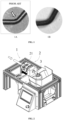
- Figure 1A illustrates a magnification of a bent portion of a wire in which surface defects (wrinkles) have been created in the inside bend.
- Patent application US20170312808A1 describes such a gripper-free bending machine comprising a wire guide which includes a hole, and a rotatable outer portion in which the wire is bent.
- This configuration does not provide a sufficiently precise and rapid bending of the wire.
- the present invention aims to provide orthodontic archwires without surface defects, as illustrated in figure 1B , and with an improved mechanical behavior and durability, so as to avoid the premature fracture of the archwire - fatigue wear.
- the present invention thus relates to an orthodontic wire bending device comprising:
- the present invention allows to minimize the distance between the exit of the wire guiding unit and the bending member.
- the force applied by the bending member to the wire is maximized, resulting in a quicker, more efficient and precise bending of the wire.
- This also allows more precise three-dimensional bending of the wire as the case may be.
- the exit is a nozzle, preferably a removable nozzle.
- this embodiment allows to employ different nozzles having different cross-sections as needed.
- the convoying system is capable of rotating about the longitudinal axis, so as to rotate the wire about the longitudinal axis. This feature allows three-dimensional bending of the wire. Moreover, it is possible to obtain the wire translation and rotation within a single system, thereby reducing the dimensions of the orthodontic wire bending device.
- the wire guiding unit comprises a tube configured to house and guide the wire.
- the tube comprises:
- the wire may be convoyed safely until the exit.
- the exit has an inner surface having an inner radius, an outer surface, and a bevel or round extending from the inner surface to outer surface, the bevel or round having a radius of curvature which is equal or greater than the inner radius, preferably equal or greater than the inner diameter.
- the presence of the bevel or round avoids the creation of surface defects in the inside bend of the wire.
- the exit may have a circular cross-section and the radius of curvature of the round may be constant.
- the exit may have a squared cross-section with at least two different rounds having two different radii of curvature.
- the wire bending unit comprises a plate capable of rotating about an axis of rotation perpendicular to the longitudinal axis, wherein the at least one bending member protrudes from said rotating plate.
- the at least one bending member may be removable from the plate, so that different bending members may be used based on the wire characteristics and/or the archwire shape to be obtained.
- the wire guiding unit comprises a hollow body having a proximal end and a distal end, the hollow body being non-rotatably connected to the convoying system and being configured to receive, at its proximal end, the wire from the convoying system and to guide it along the first direction towards the wire bending unit.
- the wire advances inside the hollow body, and it is delivered to the exit, where it is exposed to the wire bending unit and it can be bent.
- the hollow body is made up of a metal or alloy material which ensure a smooth advancement of the wire towards the exit, and prevent the onset of rotational frictions.
- the at least one wire bending members is a bending rod.
- the bending rod has a diameter which decreases along the protruding direction, preferably the rod comprises a first part of frustoconical shape and a second free part of cylindrical shape.
- the decreasing diameter allows to bend the wire so as to obtain any archwire shapes, while ensuring mechanical stability of the bending member.
- the wire bending unit further comprises a wire cutting member, preferably the wire cutting member is a rod having a sharp edge.
- the wire cutting function is integrated in the wire bending unit, and there is no need to provide a separate wire cutting unit.
- the wire bending unit comprises one bending member, preferably capable of a rotation around a center of rotation of at least180°, preferably at least 200°.
- the wire bending unit comprises one bending member capable of a translation along a direction perpendicular to the first plane.
- the wire bending unit comprises one bending member and the convoying system is capable of a rotation about the longitudinal axis larger than 180°, preferably larger than 360°, so as to provide a second order bending.
- the wire bending unit comprises two bending members, preferably separated by an angular distance comprised between 10° and 170°, more preferably between 45° and 120°, even more preferably, equal to 90°.
- the convoying system may be capable of a rotation about the longitudinal axis of an angle comprised between 0° and 180°, so as to provide a second order bending.
- the present invention also relates to an orthodontic wire bending system comprising:
- the controller allows to operate the different units of the orthodontic wire bending device so as to obtain the desired archwire shape.
- the controller is configured to receive, as input, a file comprising a list of bending instructions and to operate the orthodontic wire bending device on the basis of the bending instructions in the file.
- the bending instructions are obtained from a digital model of the desired archwire shape.
- system further comprising a wire detection unit for detecting the presence of the wire, said wire detection unit being preferably installed between the exit of the wire guiding unit and the wire bending unit.
- the system comprises a human-machine interface connected to the controller.
- the human-machine interface may be used to visualize a three-dimensional model of a subject dentition, and to create a digital model of a customized archwire.
- the system may comprise a processor configured to convert the digital model of the customized archwire into bending instructions.
- the present invention also relates to a method of manufacturing an orthodontic archwire with the orthodontic wire bending device according to any one of claims 1-16, the method comprising:
- This method allows to efficiently and accurately bend the wire, without introducing surface defects.
- the archwire which is obtained is more resistant to the mechanical solicitation and the acidic environment of the oral cavity.
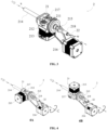
- the present invention relates to an orthodontic wire bending device 1 comprising a wire guiding unit 2, and a wire bending unit 3, as shown in figures 2 , 3 and 7 .
- proximal refers to an element, or the extremity of an element, which is closer to the wire guiding unit 1; whereas the term “distal” refers to an element, or an element extremity, which is closer to wire bending unit 3.
- the wire guiding unit 2 comprises a convoying system 21 for driving the wire, and an exit 22 for delivering the wire.
- the wire guiding unit 2 is configured to guide the wire in a first direction (represented by the white arrow in figure 2 ) along a longitudinal axis x through the exit 22.
- the wire bending unit 3 is configured to receive the wire w delivered by the exit of the wire guiding unit 2.
- Said wire bending unit 3 comprises at least one wire bending member 31, 32, which is capable of rotating around a center of rotation C in a first plane P including the longitudinal axis x.
- the axis of rotation passing through C of the bending member is perpendicular to the plane P, and C is on the longitudinal axis x.
- the wire advances through the device in a stepwise manner from the wire guiding unit 2 towards the wire bending unit 3, along the longitudinal axis x. After an advancement step, the wire is bent at the wire bending unit 3 of a first bending angle ⁇ . At the next advancement step, the wire may be bent at the wire bending unit 3 of a second bending angle, and so on, until the desired archwire shape is obtained.
- the wire guiding unit 2 comprises a convoying system 21 for driving the wire w, and an exit 22 for delivering the wire.
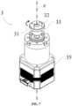
- the exit 22 is a nozzle. More in particular, the exit 22 is a nozzle having the shape of a composite solid: a proximal hexagonal prism and a distal cone; the hexagonal prism allowing to screw efficiently the nozzle on the device. In another embodiment, the exit 22 is a nozzle having a proximal cylindric shape and a distal cone; mounted with a pressure screw.
- the convoying system 21 may comprise a pair of rollers, or gears, capable of rotating about an axis perpendicular to the longitudinal axis x, so that, when the wire w passes in between the two rollers, the rotation of the rollers results in the wire advancement.
- Several transmission systems may be used to drive the rollers, or gears, in rotation: for instance, a driver may be connected to a driving gear via a shaft, or the rollers may be belt-driven. Throughout this disclosure, drivers may be advantageously motors.
- Figure 3 represents a perspective view of the wire guiding unit 2 of the present invention according to one particular embodiment in which the convoying system 21 comprises a driving roller 211, a driven roller 212, a driver 213 connected to the driving roller 211 and configured to drive the rollers 211, 212 in rotation, and a tube 214 placed upstream of said rollers.
- the convoying system 21 comprises a driving roller 211, a driven roller 212, a driver 213 connected to the driving roller 211 and configured to drive the rollers 211, 212 in rotation, and a tube 214 placed upstream of said rollers.
- the wire guiding unit 2 comprises a tube 214 configured to house and guide the wire; which may be installed upstream, downstream of the convoying system 21, or inside the convoying system 21.
- the convoying system 21 is capable of rotating about the longitudinal axis x, so as to rotate the wire w about the axis x.
- FIG. 3 One example of a rotatable convoying system 21 according to the present invention is illustrated in figure 3 .
- the convoying system 21 is capable of rotating about the longitudinal axis x, as it can be driven in rotation by a belt and pulley assembly 215, connected to a driver 216.
- the convoying system 21 therein illustrated comprises a support element 217 on which the rollers 211, 212 and the driver 213 are mounted.
- the support element 217 is connected to the belt and pulley assembly 215 and it has the twofold function of bearing the rollers 211, 212 and the driver 213, and permitting the rotation of the convoying system 21 about the axis x.
- the rotation of the convoying system 21 allows to modify the bending plane at each advancement step of the wire, so as to provide a second order bending.
- the total length to be covered by the wire is also reduced, because the wire translation and rotation are simultaneously obtained inside the wire guiding unit 2. With this embodiment, it is therefore possible to reduce the dimensions of the orthodontic wire bending device 1.
- the convoying system 21 is capable of rotating about the longitudinal axis x up to an angle of 180°, preferably of at least an angle of 180°, more preferably of at least an angle of 360°.
- a rotation angle equal or greater than 360° is especially interesting in a configuration with only one bending member.
- FIGS 4A and 4B One example of this embodiment is illustrated in figures 4A and 4B .
- the wire guiding unit 2 is represented in a first position in which the rotation angle of the convoying system 21 is 90°, and in figure 4B it is represented in a second position in which the rotation angle is 180°.
- the wire guiding unit 2 may comprise a tube 214 configured to house and guide the wire.
- the tube 214 is made up of a metal or a metal alloy; more preferably, a medical grade metal or metal alloy.
- suitable metals or a metal alloys comprise: stainless steel, aluminum, cobalt-chrome alloy, titanium, nickel-titanium alloy (nitinol).
- the external cover is made up of a medical grade metal or alloy material.
- the tube 214 comprises an external cover and an inner sheath.
- the external cover is made up of a metal or a metal alloy.
- the inner sheath is a polymeric sheath.
- the inner sheath is made up of a thermoplastic elastomer, such as for instance thermoplastic urethane (TPU) elastomer, thermoplastic elastic olefin (TEO), styrene-ethylene-butylene-styrene (SEBS), polyether-ester block copolymers (COPE), thermoplastic polyether block amide (PEBA), or a combination thereof.
- a thermoplastic elastomer such as for instance thermoplastic urethane (TPU) elastomer, thermoplastic elastic olefin (TEO), styrene-ethylene-butylene-styrene (SEBS), polyether-ester block copolymers (COPE), thermoplastic polyether block amide (PEBA), or a combination thereof.
- TPU thermoplastic urethane
- TEO thermoplastic elastic olefin
- SEBS styrene-ethylene-butylene-styrene
- COPE polyether-ester block
- thermoplastic elastomer is a medical grade thermoplastic elastomer.
- the wire guiding unit 2 may further comprise a hollow body 218 having an external surface and an internal surface defining an internal hollow portion.
- the hollow body 218 extends, along a direction parallel to the longitudinal axis x, from the convoying system 21 to the exit 22 so that the wire exiting from the convoying system 21, it enters the hollow body 218, it advances inside the internal hollow portion, and it is delivered to the exit 22 of the wire guiding unit 2.
- the wire is exposed to the wire bending unit 3 and it can be bent by the bending member 31, 32.
- the hollow body 218 is made up of a metal or alloy material.
- Metal or alloy materials prevent rotational friction that might result from rotation of the wire relative to the inner surface of the hollow body 218. This friction may increase the risk of crack formation, and cause energy losses.
- the wire guiding unit 2 comprise an exit 22 which is located, along the first direction, beyond the center of rotation C of the bending member 31, 32.
- the exit 22 is a nozzle, preferably a removable nozzle.
- This embodiment allows to employ different nozzles having different cross-sections. It is therefore possible to selected the nozzle whose cross-section is optimized to the cross-section of the wire being used and/or to the archwire shape to be obtained.
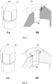
- the inner surface of the exit 22 has a circular or elliptical cross-section, as shown in figure 5 .
- the exit 22 has an inner surface which is beveled or rounded, i.e. filleted on an exterior corner.
- the presence of the bevel or round ensures that the wire, during bending, does not face sharp edges. Sharp edges may cause surface defects such as wrinkles in the inside bend of the wire w.
- the exit 22 may have an inner surface having an inner diameter Dt, an outer surface.
- an inner surface which is beveled or rounded it is meant that a bevel or rounded extends from the inner surface to the outer surface, with a radius of curvature r.
- the radius of curvature r is equal or greater than the radius of the inner surface Dt/2, preferably equal or greater than the diameter of the inner surface Dt.
- the radius of curvature of the bent wire be larger than the radius of the wire itself.
- the radius of curvature r of the round is constant.
- the radius of curvature may be variable.
- the exit 22 of figure 6 is a nozzle whose inner surface has a squared cross-section, in which two opposite sides are not beveled, i.e. they have a zero radius of curvature, and the other two opposite sides are rounded, i.e. they have a non-zero radius of curvature.
- the radiuses of curvature of the rounded sides may be identical or, as illustrated in figure 6B , may differ.
- the radius of curvature r R of the right-side round is larger than the radius of curvature r L of the left side round.
- Having a variable radius of curvature allows to obtain, with a single exit 22, different bend radius. For instance, with the nozzle of figure 6 , it is possible to provide smaller bend radius by using the bending member 31, 32 which would bend the wire w toward the left side of the exit 22, and larger bend radius by using the bending member 31, 32, as it would bend the wire toward the right side of the exit 22.
- the inner surface of the exit 22 has a square or rectangular cross-section, as shown in figure 6 .
- cross-section of the inner surface is not circular, by inner diameter Dt it is meant the shortest dimension of the cross-section, for instance the length of one side for a square cross-section, or the minor axis for an elliptical cross-section.
- the exit 22 is tapered, i.e. it has an inner surface having a constant inner diameter Dt, and an outer surface having an outer diameter which decreases along the first direction. Examples of this embodiment are visible in figures 5 and 6 . In these embodiments, the exit 22 has a hollow frustoconical shape.
- the orthodontic wire bending device 1 further comprises a wire bending unit 3 configured to receive the wire w delivered by the exit 22 of the wire guiding unit 2 and comprising at least one bending member 31, 32.
- the wire bending unit 3 comprises two bending members 31, 32.
- a rotation of the convoying system 21 of an angle comprised between 0° and 180° is sufficient to provide a second order bending.
- Such a small rotation of the two bending members 31, 32 allows to render the convoying system 21 less complex and more stable.
- the wire bending unit 3 may comprise only one bending member 31, 32.
- One example of this embodiment is shown in figure 8C .
- the convoying system 21 is preferably capable of a rotation larger than 180°, and more preferably larger than 360°. Such a large rotation advantageously allows to access totally the 3D space for all orientations of the archwire under formation. Therefore, second order bending becomes more accessible.
- the wire bending unit 3 of the first configuration is better shown in figure 7 .
- the two bending members 31, 32 may be mounted on the same support capable of rotating around the center of rotation C. Having the bending members 31, 32 mounted on the same support allows to reduce the dimensions of the bending unit 3.
- the two bending members 31, 32 may be mounted on two distinct supports.
- the support on which the at least one bending member 31, 32 is mounted may be driven in rotation by a driver 35, as shown in figure 7 .
- the support is a plate 33.
- the bending members 31, 32 are rods perpendicularly protruding from the plate 33.
- the angular distance between the two bending members 31, 32 is comprised between 10° and 170°.
- the angular distance between the two bending members 31, 32 is comprised between 45° and 120°; more preferably, it is equal to 90°.
- the combination of: (i) the angular distances between the bending members 31, 32 and (ii) the diameter of said bending members 31, 32 allows to obtain an archwire which reproduces the shape of the interproximal space, indicated by the white arrows in figure 9 .
- the contour of the teeth comprises a series of concavities and convexities which are smooth on the surface of the teeth. In the interproximal spaces, such concavities and convexities become harsh, and the contour of the teeth displays sharper angles. Most archwire reproduce the contour of each tooth with sufficient fidelity, but they are unable to fit inside the interproximal spaces, because of the difficulty of obtaining such sharp angles with the conventional archwire manufacturing process.
- the archwire obtained with the present invention is a three-dimensional archwire.
- the angular distance between the bending members 31, 32 and their shape allows to accurately reproduce such interproximal spaces, without creating surface defects (such as wrinkles) on the wire w.
- the reference position of the plate 33 may be defined as the position in which the two wire bending members 31, 32 are at the same distance from the exit 22.
- the wire bending unit 3 of the second configuration comprises only one bending member 31, 32 (for instance, only the first bending member 31).
- a larger rotation e.g. , a whole clockwise rotation, depending on the desired final shape of the wire w
- a larger rotation e.g. , a whole clockwise rotation, depending on the desired final shape of the wire w
- the bending unit 3 may be configured to ensure the translation of the bending member 31 in a direction perpendicular to the plane of the rotation (e.g. , in a vertical direction for a horizontal plane of rotation).
- this embodiment allows to bend a first side of the wire, then to displace the bending member 31 away from the bent side, and displace it in proximity of the other side of the wire w, along a trajectory which is shorter than a whole rotation.
- this embodiment allows to shorten the trajectory of the bending member 31 between the first side and the other side of the wire w (and, accordingly, to provide a faster bending of the wire w) by providing a bending unit 3 which has a higher number of degrees of freedom (DOFs).
- DOEs degrees of freedom
- the bending unit 3 has two DOFs so as to ensure: (i) the rotation around the center C and (ii) the translation, for instance along a vertical direction, of the bending member 31.
- the reference position of the plate 33 may be defined as the position in which said bending member 31, 32 faces the exit 22.
- the plate 33 is capable of rotating around a vertical axis z which is perpendicular to the longitudinal axis, and which includes the center of rotation.
- the bending member 31, 32 may be mounted so that it protrudes from a surface of the plate 33.
- a rotation of the plate about the vertical axis results in the rotation of the bending member 31, 32 around the center of rotation C.
- FIG 2 One example of this embodiment is illustrated in figure 2 .
- two wire bending members 31, 32 are provided as cylindrical rods which protrude perpendicularly from the plate.
- the plate 33 is capable of rotating about the vertical axis z of an angle up to 180°.
- the plate 33 is capable of a clockwise rotation up to 90° and a counterclockwise rotation up to 90°, from the reference position.
- the first plane P includes the longitudinal axis x.
- the plane P is better shown in figure 8 , which illustrates a simplified top view of the wire guiding unit 2 and the wire bending unit 3 of the present invention on the plane P.
- the angles ⁇ and ⁇ , the distance R between the center of rotation C and the wire bending members 31, 32, and the distance d between the center of rotation C and the exit are also represented.
- the wire w advances through the device in a stepwise manner from the wire guiding unit 2 towards the wire bending unit 3, along the longitudinal axis x.
- the wire w is bent at the wire bending unit 3.
- bending angle ⁇ it is meant the angle between the longitudinal axis x and the bent portion of the wire, which has as vertex the exit of the wire guiding unit 1.
- wire bending is a sum of elastic deformation and plastic deformation, only the latter remaining after elastic recovery when bending member is withdrawn. Equation (e1) holds true as far as bending member is in contact with the wire: when bending member applies a force onto the wire; and when the wire is recovering elastically while the bending wire is withdrawn.
- angle ⁇ of bending is defined with the angle ⁇ related to the position of the bending member at this instant. So as to reach a bending angle ⁇ for the wire, bending member has to reach an angle larger than angle ⁇ defined by equation (e1). Equation (e1) corresponds to the geometry of bend after elastic recovery.
- the wire may be bent at the wire bending unit 3 of a second bending angle, and so on, until the desired archwire shape is obtained.
- the exit 22 of the wire guiding unit 2 is located, along the first direction, beyond the center of rotation C.
- the abscissa of the exit 22 is positive.
- this embodiment allows to minimize the distance between the exit 22 of the wire guiding unit 2 and the bending member 31, 32.
- the force applied by the bending member 31, 32 to the wire w is maximized.
- the presence of two bending members 31, 32 in the first configuration allows to obtain large bending angles ⁇ with small angular displacements ⁇ of the bending members 31, 32.
- the bending members 31, 32 are rotated in a counterclockwise manner to bend the wire and pass from figure 8A to figure 8B , so that the wire can be bent by the first bending member 31. From the configuration of figure 8B , to bend the wire in the opposite direction, it is sufficient to rotate the bending members 31, 32 in a clockwise manner, so as to bend the wire with the second bending member 32.
- the bending member 31, 32 is able to turn around a center of rotation C in the first plane P.
- the axis of rotation passing through C of the bending member is perpendicular to the plane P and preferably, center of rotation C is on the longitudinal axis x.
- having the rotation of the bending member 31, 32 in the plane P, which includes the longitudinal axis x allows to reduce the dimensions of the wire bending unit 3.
- it allows to bend the wire w more rapidly, when compared to a coaxial bending unit, i.e. a bending unit in which the bending member rotates in a plane perpendicular to the plane in which the longitudinal axis lies.
- a coaxial bending unit would require a large distance between the center of rotation C and the bending member 31, 32, because the wire guiding unit 2 indeed would act as a physical obstacle, precluding the possibility to have the bending member proximate to the exit 22.
- a large distance between the center of rotation C and the bending member 31, 32, should be avoided because (i) the bending unit 3, and hence the orthodontic wire bending device 1, would occupy a large volume and (ii) the bending member 31, 32 would require more time to reach the wire to be bent.
- the rotation of the support of the bending unit 3, allows to move the wire bending member 31, 32 along a circular arc trajectory.
- the dashed line represents a portion of the trajectory which can be covered by the bending members 31, 32.
- the diameter of the bending member 31, 32 is comprised between 0,1 mm and 100 mm, preferably between 0,1 mm and 10 mm.
- the diameter of the bending member 31, 32 is at least 0,3 mm.
- the diameter of the bending member 31, 32 is comprised between 0,3 mm and 5 mm. Such diameters allow to obtain small inside bend radius, which are especially needed to reproduce the contour of the interproximal space i.e. , the space between adjacent teeth in a dental arch.
- the bending member 31, 32 has a conical shape.
- the bending member 31, 32 has a cylindrical shape.
- the bending member 31, 32 has the shape of a composite solid.
- the edges shared by adjacent solids may be beveled, as illustrated for instance in figure 10 .
- the decreasing diameter allows to provide a bending member 31, 32 which has a smaller diameter at its free end, and which has a larger diameter at its base.
- this embodiment allows to obtain all the relevant archwire shapes, while ensuring mechanical stability to the bending member 31, 32, due to the larger base. Besides, centering, effort transfer from device to bending member, stability of geometry are improved with a larger base.
- This specific structure allows a better distribution of bending moment and limit the deflection of the bending member on one hand and limits misalignments, parallelism defects or contact defects between the bending member and the wire.
- the two bending members 31, 32 have the same shape.
- the two bending members 31, 32 have different shapes.
- the bending members 31, 32 protrude from a rotating plate 33, and their diameter decreases along the protruding direction. More in particular, these bending members 31, 32 have the shape of a composite solid comprising, along a direction protruding from the rotating plate 33: a first cylinder, a truncated cone, and a second cylinder, with a diameter smaller than that of the first cylinder.
- the bending member 31, 32 is not detachable from the rotating support.
- it may have an extremity which is embedded in the rotating support, it may be integrally manufactured with the rotating support or it may be attached to it.
- the bending member 31, 32 is removable, i.e. , it can be detached from the rotating support.
- they may have an extremity which is screwed, or snap-fitted in the rotating support; or they may be mounted on the rotating support with any other reversible attachment method.
- this embodiment allows to remove and replace the bending members 31, 32.
- Different bending members 31, 32 having different shapes can be used.
- the types and number of final archwire shape which can be obtained depends on the shape of the bending members 31, 32. Therefore, with this embodiment it is possible to use the same orthodontic bending device 1 for manufacturing a wide number of archwire: it is sufficient to mount the bending member 31, 32 whose shape is optimized for the archwire to be manufactured.
- the present bending device further comprises a wire cutting member 34 for cutting the wire.
- the wire cutting member is mounted on an articulated arm able to come in contact with the wire w at the exit 22 of the wire guiding unit 2.
- the wire bending members 31, 32 and the wire cutting member 34 are mounted on the same support. More preferably, they are mounted on a rotating plate 33 so that they protrude from a surface of the rotating plate 33, as shown in figure 11 .
- the cutting member 34 and the wire bending members 31, 32 perpendicularly protrude from the rotating plate 33.
- the cutting member 34 may be made of a material having a high hardness.
- it may be made of hardened steel, high speed steel (HSS) or tungsten carbide.
- the cutting member 34 has a flat surface 341 provided with a sharp edge for cutting the wire.
- the cutting member is capable of rotating around the center of rotation C, and the flat surface 341 is configured to be tangential to the exit 22 when the cutting member lies on the longitudinal axis.
- the wire cutting member 34 is not equidistant to the two bending rods.
- the wire cutting member 34 is at an angular distance larger than 90° from the first bending member 31, and at an angular distance smaller than 45° from the second bending member 32, or vice-versa.
- this embodiment is illustrated in figure 11 .
- wire cutting member 34 in proximity of one of the bending members 31, 32 allows to cut the wire right after the last bending operation. Moreover, a small rotation of the wire cutting member 34 is sufficient to cut the wire due to (i) the proximity of the cutting member 34 with one of the bending members 31, 32, combined with (ii) the presence of a flat surface 341 which is tangential to the exit 22 when the cutting member 34 lies on the longitudinal axis.
- the rotation of the cutting member 34 needed to cut the wire is smaller than 20°; preferably, smaller than 15°.
- the present invention also relates to an orthodontic wire bending system comprising:
- the orthodontic wire bending system further comprises a wire detection unit for detecting the presence of the wire.
- the wire detection unit is installed between the wire guiding unit 2 and the wire bending unit 3.
- the wire detection unit is installed between the exit 22 and the wire bending unit 3.
- the wire detection unit comprises a camera.
- the wire detection unit comprises an electrical circuit and a sensor for measuring the electrical current along said electrical circuit, so as to detect electrical current variations due to the presence or absence of the wire.
- the programmable controller of the orthodontic wire bending system comprises the hardware and software for controlling the drivers which drive the wire guiding unit 2 and the wire bending unit 3, i.e. the drivers 213, 35.
- the programmable controller may further control a driver 216 for rotating the convoying system 21.
- the programmable controller receives, as input, a file comprising a list of bending instructions.
- the programmable controller operates the bending device 1 on the basis of the bending instructions in the file.
- the programmable controller is configured to receive the file with the bending instructions from an external source.
- the orthodontic bending device comprises a human-machine interface connected to the programmable controller, and the human-machine interface comprises a display and an input device, as shown in figure 2 .
- the programmable controller comprises a processor configured to execute a computer program for generating said bending instructions, and a storage medium for storing a file comprising said instructions.
- the processor may be configured to receive radiological images representing the dentition of a subject, and the computer program may be configured to:
- the user input comprises a list of anatomical locations representing the desired position of bracket bodies.
- the user input comprises a list of anatomical locations representing interproximal spaces.
- the computer program is further configured to verify the feasibility of the bending instructions and:
- the file comprising the bending instructions is a derived form a .STL file corresponding to the desired archwire.
- the present invention also relates to a method of manufacturing an orthodontic archwire with the orthodontic wire bending device 1 according to any one of the embodiments described hereinabove.
- the manufacturing method comprises:
- Feeding step and rotating step may be repeated until a full orthodontic archwire is obtained.
- the angle ⁇ may be up to 360°.
- the angle ⁇ is smaller than 360°.
- the method is a method for designing and manufacturing an orthodontic archwire, the method comprising:
- the convoying system 21 may be capable of rotating about the longitudinal axis.
- the programmable controller may further operate a driver 216 configured to drive in rotation said convoying system 21.
- the present orthodontic archwire manufacturing method allows to:
- the method of the present invention is further for cutting an archwire manufactured with the orthodontic bending device 1.
- the cutting of the archwire comprises:
- the bending members 31, 32 and the cutting member 34 are mounted on the same rotating plate 33.
- each of the bending members 31, 32 and the cutting member 34 may be mounted on an independent rotating support.
- a clockwise rotation of the plate 33 comprising the bending members 31, 32 provides the last bending ( figure 12A ) to the wire w.
- a second clockwise rotation brings the cutting member 34 in contact with the wire w ( figure 12B ).
- the flat surface 341 of the cutting member 34 is tangential to the exit 22, and it allows to cut the wire.
- the cutting member 34 allows to cut of the wire w precisely, and without damaging it.
Landscapes
- Health & Medical Sciences (AREA)
- Oral & Maxillofacial Surgery (AREA)
- Dentistry (AREA)
- Epidemiology (AREA)
- Life Sciences & Earth Sciences (AREA)
- Animal Behavior & Ethology (AREA)
- General Health & Medical Sciences (AREA)
- Public Health (AREA)
- Veterinary Medicine (AREA)
- Engineering & Computer Science (AREA)
- Mechanical Engineering (AREA)
- Dental Tools And Instruments Or Auxiliary Dental Instruments (AREA)
Claims (19)
- Vorrichtung (1) zum Biegen von kieferorthopädischen Drähten, umfassend:- eine Drahtführungseinheit (2), die ein Fördersystem zum Antreiben des Drahts (w) und einen Ausgang (22) zum Abgeben des Drahts (w) umfasst, wobei die Drahtführungseinheit so konfiguriert ist, dass sie den Draht in einer ersten Richtung entlang einer Längsachse durch den Ausgang (22) führt, und- eine Drahtbiegeeinheit (3), die mit dem durch den Ausgang (22) abgegebenen Draht gespeist wird, die mindestens ein Drahtbiegeelement (31, 32) umfasst, wobei das mindestens eine Drahtbiegeelement (31, 32) in der Lage ist, sich um einen Drehpunkt (C) in einer ersten Ebene, die die Längsachse beinhaltet, derart zu drehen, dass, wenn der Draht aus dem Ausgang (22) herauskommt, eine Drehung des mindestens einen Biegeelements (31, 32) um den Drehpunkt (C) zum Biegen des Drahts (w) nahe des Ausgangs (22) führt,wobei sich der Ausgang (22) der Drahtführungseinheit (2) entlang der ersten Richtung jenseits des Drehpunkts (C) befindet, undwobei die Drahtbiegeeinheit (3) ein Biegeelement (31, 32) umfasst, das zu einer Verschiebung entlang einer Richtung senkrecht zur ersten Ebene fähig ist.
- Vorrichtung zum Biegen von kieferorthopädischen Drähten nach Anspruch 1, wobei der Ausgang (22) eine Düse, bevorzugt eine abnehmbare Düse, ist.
- Vorrichtung zum Biegen von kieferorthopädischen Drähten nach Anspruch 1, die derart konfiguriert ist, dass eine Drehung des mindestens einen Biegeelements (31, 32) um einen Winkel α zum Biegen des Drahts (w) nach elastischer Rückstellung um einen Winkel β führt, wobei die Beziehung zwischen α und β durch die Gleichung (e1) gegeben ist:

- Vorrichtung (1) zum Biegen von kieferorthopädischen Drähten nach einem der Ansprüche 1 bis 3, wobei das Fördersystem (21) fähig ist, sich um die Längsachse zu drehen, um den Draht (w) um die Längsachse zu drehen.
- Vorrichtung (1) zum Biegen von kieferorthopädischen Drähten nach einem der Ansprüche 1 bis 4, wobei die Drahtführungseinheit (2) ein Rohr (214) umfasst, das so konfiguriert ist, dass es den Draht (w) beherbergt und führt.
- Vorrichtung (1) zum Biegen von kieferorthopädischen Drähten nach Anspruch 5, wobei das Rohr (214) umfasst:a. eine äußere Abdeckung, die bevorzugt aus einem Metall oder einem Legierungsmaterial besteht, undb. eine innere Hülle, die bevorzugt aus einem thermoplastischen Elastomer medizinischer Güte besteht.
- Vorrichtung (1) zum Biegen von kieferorthopädischen Drähten nach einem der Ansprüche 1 bis 6, wobei der Ausgang (22) eine Innenfläche, die einen Innenradius aufweist, eine Außenfläche und eine Abschrägung oder Rundung aufweist, die sich von der Innenfläche zur Außenfläche erstreckt, wobei die Abschrägung oder Rundung einen Krümmungsradius r aufweist, der gleich dem oder größer als der Innenradius Dt/2, bevorzugt gleich dem oder größer als der Innendurchmesser Dt ist.
- Vorrichtung (1) zum Biegen von kieferorthopädischen Drähten nach einem der Ansprüche 1 bis 7, wobei die Drahtbiegeeinheit (3) eine Platte (33) umfasst, die fähig ist, sich um eine zur Längsachse senkrechte Drehachse zu drehen, wobei das mindestens eine Biegeelement (31, 32) von der sich drehenden Platte (33) vorspringt.
- Vorrichtung (1) zum Biegen von kieferorthopädischen Drähten nach einem der Ansprüche 1 bis 8, wobei die Drahtführungseinheit (2) einen Hohlkörper (218) umfasst, der ein proximales Ende und ein distales Ende aufweist, wobei der Hohlkörper (218) nicht drehbar mit dem Fördersystem (21) verbunden ist und so konfiguriert ist, dass er an seinem proximalen Ende den Draht (w) vom Fördersystem (21) aufnimmt und ihn entlang der ersten Richtung zur Drahtbiegeeinheit (3) hin führt.
- Vorrichtung (1) zum Biegen von kieferorthopädischen Drähten nach einem der Ansprüche 1 bis 9, wobei das mindestens eine Biegeelement (31, 32) ein Biegestab ist.
- Vorrichtung (1) zum Biegen von kieferorthopädischen Drähten nach Anspruch 10, wobei der Biegestab einen Durchmesser aufweist, der entlang der Vorsprungsrichtung abnimmt, bevorzugt wobei der Stab einen ersten Teil mit kegelstumpfförmiger Form und einen zweiten freien Teil mit zylindrischer Form umfasst.
- Vorrichtung zum Biegen von kieferorthopädischen Drähten nach einem der Ansprüche 1 bis 11, wobei die Drahtbiegeeinheit (3) weiter ein Drahtschneideelement (34) umfasst, bevorzugt wobei das Drahtschneideelement (34) ein Stab ist, der eine flache Fläche (341) aufweist.
- Vorrichtung zum Biegen von kieferorthopädischen Drähten nach Anspruch 1 bis 12, wobei die Drahtbiegeeinheit (3) ein Biegeelement (31, 32) umfasst, das bevorzugt zu einer Drehung von mindestens 180°, bevorzugt mindestens 200°, um einen Drehpunkt (C) fähig ist.
- Vorrichtung zum Biegen von kieferorthopädischen Drähten nach Anspruch 13, wobei das Fördersystem (21) zu einer Drehung von mehr als 180°, bevorzugt mehr als 360°, um die Längsachse fähig ist, um eine Biegung zweiter Ordnung bereitzustellen.
- Vorrichtung zum Biegen von kieferorthopädischen Drähten nach einem der Ansprüche 1 bis 11, wobei die Drahtbiegeeinheit (3) zwei Biegeelemente (31, 32) umfasst, die bevorzugt um einen Winkelabstand im Bereich zwischen 10° und 170°, bevorzugter zwischen 45° und 120°, noch bevorzugter gleich 90°, getrennt sind.
- Vorrichtung zum Biegen von kieferorthopädischen Drähten nach Anspruch 15, wobei das Fördersystem (21) zu einer Drehung um einen Winkel im Bereich zwischen 0° und 180° um die Längsachse fähig ist, um eine Biegung zweiter Ordnung bereitzustellen.
- System zum Biegen von kieferorthopädischen Drähten, umfassend:a. eine Vorrichtung (1) zum Biegen von kieferorthopädischen Drähten nach einem der Ansprüche 1 bis 16, wobei die Vorrichtung (1) zum Biegen von kieferorthopädischen Drähten auf Steuerbefehle reagiert;b. eine Antriebsanordnung, die einen ersten Antrieb (213), der mit der Drahtführungseinheit (2) wirkverbunden und so konfiguriert ist, dass er den Draht in der Führungseinheit antreibt, und einen zweiten Antrieb (35) umfasst, der mit der Drahtbiegeeinheit (3) wirkverbunden und so konfiguriert ist, dass er das mindestens eine Biegeelement (31, 32) drehend antreibt; undc. eine programmierbare Steuerung, die so konfiguriert ist, dass sie Steuerbefehle an die Antriebe der Antriebsanordnung sendet, um die kieferorthopädische Biegevorrichtung (1) zu betreiben.
- System zum Biegen von kieferorthopädischen Drähten nach Anspruch 17, das weiter eine Drahterkennungseinheit zum Erkennen des Vorhandenseins des Drahts (w) umfasst, wobei die Drahterkennungseinheit bevorzugt zwischen dem Ausgang der Drahtführungseinheit (2) und der Drahtbiegeeinheit (3) installiert ist.
- Verfahren zum Herstellen eines kieferorthopädischen Bogendrahts mit der Vorrichtung (1) zum Biegen von kieferorthopädischen Drähten nach einem der Ansprüche 1 bis 16, wobei das Verfahren umfasst:- Führen des Drahts (w) in einer ersten Richtung entlang der Längsachse durch die Drahtführungseinheit (2) und Abgeben des Drahts (w) durch den Ausgang (22) aus der Drahtführungseinheit (2) heraus;- Speisen der Drahtbiegeeinheit (3) mit dem aus dem Ausgang (22) abgegebenen Draht (w); und- Drehen des mindestens einen Biegeelements (31, 32) um einen vordefinierten Winkel α um den Drehpunkt (C), um den Draht (w) zu biegen.
Applications Claiming Priority (2)
| Application Number | Priority Date | Filing Date | Title |
|---|---|---|---|
| EP21305387.9A EP4062864A1 (de) | 2021-03-26 | 2021-03-26 | Vorrichtung und verfahren zum biegen von kieferorthopädischen drähten |
| PCT/EP2022/058029 WO2022200620A1 (en) | 2021-03-26 | 2022-03-25 | Orthodontic wire bending device and method |
Publications (3)
| Publication Number | Publication Date |
|---|---|
| EP4284293A1 EP4284293A1 (de) | 2023-12-06 |
| EP4284293B1 true EP4284293B1 (de) | 2025-02-12 |
| EP4284293C0 EP4284293C0 (de) | 2025-02-12 |
Family
ID=75497887
Family Applications (2)
| Application Number | Title | Priority Date | Filing Date |
|---|---|---|---|
| EP21305387.9A Withdrawn EP4062864A1 (de) | 2021-03-26 | 2021-03-26 | Vorrichtung und verfahren zum biegen von kieferorthopädischen drähten |
| EP22719238.2A Active EP4284293B1 (de) | 2021-03-26 | 2022-03-25 | Vorrichtung und verfahren zum biegen von kieferorthopädischen drähten |
Family Applications Before (1)
| Application Number | Title | Priority Date | Filing Date |
|---|---|---|---|
| EP21305387.9A Withdrawn EP4062864A1 (de) | 2021-03-26 | 2021-03-26 | Vorrichtung und verfahren zum biegen von kieferorthopädischen drähten |
Country Status (6)
| Country | Link |
|---|---|
| US (1) | US20240156572A1 (de) |
| EP (2) | EP4062864A1 (de) |
| CN (1) | CN117136036A (de) |
| ES (1) | ES3014014T3 (de) |
| PL (1) | PL4284293T3 (de) |
| WO (1) | WO2022200620A1 (de) |
Families Citing this family (1)
| Publication number | Priority date | Publication date | Assignee | Title |
|---|---|---|---|---|
| JP2024071023A (ja) * | 2022-11-14 | 2024-05-24 | 株式会社リコー | 長尺材供給装置、及び曲げ加工装置 |
Family Cites Families (4)
| Publication number | Priority date | Publication date | Assignee | Title |
|---|---|---|---|---|
| US7240528B2 (en) * | 2004-11-22 | 2007-07-10 | Lingualcare, Inc. | Method and device for shaping an orthodontic archwire |
| ES2760553T3 (es) * | 2016-04-27 | 2020-05-14 | Advanced Orthodontic Solutions | Máquina de doblado de alambre |
| US11925969B2 (en) * | 2018-06-04 | 2024-03-12 | Korea Institute Of Machinery & Materials | Orthodontic wire bending device |
| KR102191740B1 (ko) * | 2018-12-17 | 2020-12-16 | 한국기계연구원 | 치아 교정용 와이어 벤딩 유닛 및 이를 포함하는 치아 교정용 와이어 벤딩기 |
-
2021
- 2021-03-26 EP EP21305387.9A patent/EP4062864A1/de not_active Withdrawn
-
2022
- 2022-03-25 EP EP22719238.2A patent/EP4284293B1/de active Active
- 2022-03-25 CN CN202280025086.6A patent/CN117136036A/zh active Pending
- 2022-03-25 US US18/551,993 patent/US20240156572A1/en active Pending
- 2022-03-25 ES ES22719238T patent/ES3014014T3/es active Active
- 2022-03-25 PL PL22719238.2T patent/PL4284293T3/pl unknown
- 2022-03-25 WO PCT/EP2022/058029 patent/WO2022200620A1/en not_active Ceased
Also Published As
| Publication number | Publication date |
|---|---|
| US20240156572A1 (en) | 2024-05-16 |
| ES3014014T3 (en) | 2025-04-16 |
| CN117136036A (zh) | 2023-11-28 |
| WO2022200620A1 (en) | 2022-09-29 |
| EP4062864A1 (de) | 2022-09-28 |
| EP4284293A1 (de) | 2023-12-06 |
| PL4284293T3 (pl) | 2025-04-28 |
| EP4284293C0 (de) | 2025-02-12 |
Similar Documents
| Publication | Publication Date | Title |
|---|---|---|
| US11072021B2 (en) | Apparatus and method for customized shaping of orthodontic archwires and other medical devices | |
| EP2427135B1 (de) | Vorrichtung und verfahren für die massgeschneiderte formung von kieferorthopädischen bogendrähten und anderen medizinischen vorrichtungen | |
| US11701205B2 (en) | System of manufacturing orthodontic wire, method for manufacturing the orthodontic wire using the same, and orthodontic wire bending machine for performing the same | |
| US6860132B2 (en) | Robot and method for bending orthodontic archwires and other medical devices | |
| CA2527056C (en) | Method and device for shaping an orthodontic archwire | |
| ES2760553T3 (es) | Máquina de doblado de alambre | |
| EP4284293B1 (de) | Vorrichtung und verfahren zum biegen von kieferorthopädischen drähten | |
| EP3225365B1 (de) | Roboter, flexibles getriebe, getriebevorrichtung und herstellungsverfahren eines flexiblen getriebes | |
| JP2015160023A (ja) | 顎位矯正装置 | |
| Jiang et al. | Recent advances in orthodontic archwire bending robot system | |
| US20210229158A1 (en) | Orthodontic wire bending device | |
| CN121244812B (zh) | 一种用于编织支架的张力可控走丝装置 | |
| CN117281639A (zh) | 一种自动化正畸弓丝曲弯制装置及方法 | |
| JP2020110466A (ja) | 加工装置 |
Legal Events
| Date | Code | Title | Description |
|---|---|---|---|
| STAA | Information on the status of an ep patent application or granted ep patent |
Free format text: STATUS: UNKNOWN |
|
| STAA | Information on the status of an ep patent application or granted ep patent |
Free format text: STATUS: THE INTERNATIONAL PUBLICATION HAS BEEN MADE |
|
| PUAI | Public reference made under article 153(3) epc to a published international application that has entered the european phase |
Free format text: ORIGINAL CODE: 0009012 |
|
| STAA | Information on the status of an ep patent application or granted ep patent |
Free format text: STATUS: REQUEST FOR EXAMINATION WAS MADE |
|
| 17P | Request for examination filed |
Effective date: 20230828 |
|
| AK | Designated contracting states |
Kind code of ref document: A1 Designated state(s): AL AT BE BG CH CY CZ DE DK EE ES FI FR GB GR HR HU IE IS IT LI LT LU LV MC MK MT NL NO PL PT RO RS SE SI SK SM TR |
|
| DAX | Request for extension of the european patent (deleted) | ||
| RAV | Requested validation state of the european patent: fee paid |
Extension state: TN Effective date: 20230828 Extension state: MA Effective date: 20230828 |
|
| GRAP | Despatch of communication of intention to grant a patent |
Free format text: ORIGINAL CODE: EPIDOSNIGR1 |
|
| STAA | Information on the status of an ep patent application or granted ep patent |
Free format text: STATUS: GRANT OF PATENT IS INTENDED |
|
| INTG | Intention to grant announced |
Effective date: 20240912 |
|
| GRAS | Grant fee paid |
Free format text: ORIGINAL CODE: EPIDOSNIGR3 |
|
| GRAA | (expected) grant |
Free format text: ORIGINAL CODE: 0009210 |
|
| STAA | Information on the status of an ep patent application or granted ep patent |
Free format text: STATUS: THE PATENT HAS BEEN GRANTED |
|
| AK | Designated contracting states |
Kind code of ref document: B1 Designated state(s): AL AT BE BG CH CY CZ DE DK EE ES FI FR GB GR HR HU IE IS IT LI LT LU LV MC MK MT NL NO PL PT RO RS SE SI SK SM TR |
|
| REG | Reference to a national code |
Ref country code: GB Ref legal event code: FG4D |
|
| REG | Reference to a national code |
Ref country code: CH Ref legal event code: EP |
|
| REG | Reference to a national code |
Ref country code: DE Ref legal event code: R096 Ref document number: 602022010533 Country of ref document: DE |
|
| REG | Reference to a national code |
Ref country code: IE Ref legal event code: FG4D |
|
| U01 | Request for unitary effect filed |
Effective date: 20250304 |
|
| REG | Reference to a national code |
Ref country code: ES Ref legal event code: FG2A Ref document number: 3014014 Country of ref document: ES Kind code of ref document: T3 Effective date: 20250416 |
|
| U07 | Unitary effect registered |
Designated state(s): AT BE BG DE DK EE FI FR IT LT LU LV MT NL PT RO SE SI Effective date: 20250312 |
|
| PGFP | Annual fee paid to national office [announced via postgrant information from national office to epo] |
Ref country code: AT Payment date: 20250417 Year of fee payment: 4 |
|
| U20 | Renewal fee for the european patent with unitary effect paid |
Year of fee payment: 4 Effective date: 20250528 |
|
| PG25 | Lapsed in a contracting state [announced via postgrant information from national office to epo] |
Ref country code: RS Free format text: LAPSE BECAUSE OF FAILURE TO SUBMIT A TRANSLATION OF THE DESCRIPTION OR TO PAY THE FEE WITHIN THE PRESCRIBED TIME-LIMIT Effective date: 20250512 |
|
| PGFP | Annual fee paid to national office [announced via postgrant information from national office to epo] |
Ref country code: PL Payment date: 20250321 Year of fee payment: 4 |
|
| PGFP | Annual fee paid to national office [announced via postgrant information from national office to epo] |
Ref country code: ES Payment date: 20250429 Year of fee payment: 4 |
|
| PG25 | Lapsed in a contracting state [announced via postgrant information from national office to epo] |
Ref country code: IS Free format text: LAPSE BECAUSE OF FAILURE TO SUBMIT A TRANSLATION OF THE DESCRIPTION OR TO PAY THE FEE WITHIN THE PRESCRIBED TIME-LIMIT Effective date: 20250612 Ref country code: NO Free format text: LAPSE BECAUSE OF FAILURE TO SUBMIT A TRANSLATION OF THE DESCRIPTION OR TO PAY THE FEE WITHIN THE PRESCRIBED TIME-LIMIT Effective date: 20250512 |
|
| PG25 | Lapsed in a contracting state [announced via postgrant information from national office to epo] |
Ref country code: HR Free format text: LAPSE BECAUSE OF FAILURE TO SUBMIT A TRANSLATION OF THE DESCRIPTION OR TO PAY THE FEE WITHIN THE PRESCRIBED TIME-LIMIT Effective date: 20250212 |
|
| PG25 | Lapsed in a contracting state [announced via postgrant information from national office to epo] |
Ref country code: GR Free format text: LAPSE BECAUSE OF FAILURE TO SUBMIT A TRANSLATION OF THE DESCRIPTION OR TO PAY THE FEE WITHIN THE PRESCRIBED TIME-LIMIT Effective date: 20250513 |
|
| PGFP | Annual fee paid to national office [announced via postgrant information from national office to epo] |
Ref country code: CH Payment date: 20250401 Year of fee payment: 4 |
|
| PG25 | Lapsed in a contracting state [announced via postgrant information from national office to epo] |
Ref country code: SM Free format text: LAPSE BECAUSE OF FAILURE TO SUBMIT A TRANSLATION OF THE DESCRIPTION OR TO PAY THE FEE WITHIN THE PRESCRIBED TIME-LIMIT Effective date: 20250212 |
|
| PG25 | Lapsed in a contracting state [announced via postgrant information from national office to epo] |
Ref country code: CZ Free format text: LAPSE BECAUSE OF FAILURE TO SUBMIT A TRANSLATION OF THE DESCRIPTION OR TO PAY THE FEE WITHIN THE PRESCRIBED TIME-LIMIT Effective date: 20250212 |
|
| PG25 | Lapsed in a contracting state [announced via postgrant information from national office to epo] |
Ref country code: SK Free format text: LAPSE BECAUSE OF FAILURE TO SUBMIT A TRANSLATION OF THE DESCRIPTION OR TO PAY THE FEE WITHIN THE PRESCRIBED TIME-LIMIT Effective date: 20250212 |
|
| PLBE | No opposition filed within time limit |
Free format text: ORIGINAL CODE: 0009261 |
|
| STAA | Information on the status of an ep patent application or granted ep patent |
Free format text: STATUS: NO OPPOSITION FILED WITHIN TIME LIMIT |
|
| PG25 | Lapsed in a contracting state [announced via postgrant information from national office to epo] |
Ref country code: MC Free format text: LAPSE BECAUSE OF FAILURE TO SUBMIT A TRANSLATION OF THE DESCRIPTION OR TO PAY THE FEE WITHIN THE PRESCRIBED TIME-LIMIT Effective date: 20250212 |
|
| PG25 | Lapsed in a contracting state [announced via postgrant information from national office to epo] |
Ref country code: IE Free format text: LAPSE BECAUSE OF NON-PAYMENT OF DUE FEES Effective date: 20250325 |
|
| 26N | No opposition filed |
Effective date: 20251113 |
|
| VS25 | Lapsed in a validation state [announced via postgrant information from nat. office to epo] |
Ref country code: MA Free format text: FAILURE TO ELECT DOMICILE IN THE NATIONAL COUNTRY Effective date: 20250513 |