EP4284132A1 - Immersion cooling system and cooling method thereof - Google Patents
Immersion cooling system and cooling method thereof Download PDFInfo
- Publication number
- EP4284132A1 EP4284132A1 EP22190308.1A EP22190308A EP4284132A1 EP 4284132 A1 EP4284132 A1 EP 4284132A1 EP 22190308 A EP22190308 A EP 22190308A EP 4284132 A1 EP4284132 A1 EP 4284132A1
- Authority
- EP
- European Patent Office
- Prior art keywords
- cooling
- liquid
- server
- storage part
- cooling liquid
- Prior art date
- Legal status (The legal status is an assumption and is not a legal conclusion. Google has not performed a legal analysis and makes no representation as to the accuracy of the status listed.)
- Pending
Links
Images
Classifications
-
- H—ELECTRICITY
- H05—ELECTRIC TECHNIQUES NOT OTHERWISE PROVIDED FOR
- H05K—PRINTED CIRCUITS; CASINGS OR CONSTRUCTIONAL DETAILS OF ELECTRIC APPARATUS; MANUFACTURE OF ASSEMBLAGES OF ELECTRICAL COMPONENTS
- H05K7/00—Constructional details common to different types of electric apparatus
- H05K7/20—Modifications to facilitate cooling, ventilating, or heating
- H05K7/20709—Modifications to facilitate cooling, ventilating, or heating for server racks or cabinets; for data centers, e.g. 19-inch computer racks
- H05K7/208—Liquid cooling with phase change
- H05K7/20818—Liquid cooling with phase change within cabinets for removing heat from server blades
-
- H—ELECTRICITY
- H05—ELECTRIC TECHNIQUES NOT OTHERWISE PROVIDED FOR
- H05K—PRINTED CIRCUITS; CASINGS OR CONSTRUCTIONAL DETAILS OF ELECTRIC APPARATUS; MANUFACTURE OF ASSEMBLAGES OF ELECTRICAL COMPONENTS
- H05K7/00—Constructional details common to different types of electric apparatus
- H05K7/20—Modifications to facilitate cooling, ventilating, or heating
- H05K7/2029—Modifications to facilitate cooling, ventilating, or heating using a liquid coolant with phase change in electronic enclosures
- H05K7/203—Modifications to facilitate cooling, ventilating, or heating using a liquid coolant with phase change in electronic enclosures by immersion
-
- H—ELECTRICITY
- H05—ELECTRIC TECHNIQUES NOT OTHERWISE PROVIDED FOR
- H05K—PRINTED CIRCUITS; CASINGS OR CONSTRUCTIONAL DETAILS OF ELECTRIC APPARATUS; MANUFACTURE OF ASSEMBLAGES OF ELECTRICAL COMPONENTS
- H05K7/00—Constructional details common to different types of electric apparatus
- H05K7/20—Modifications to facilitate cooling, ventilating, or heating
- H05K7/2029—Modifications to facilitate cooling, ventilating, or heating using a liquid coolant with phase change in electronic enclosures
- H05K7/20318—Condensers
-
- H—ELECTRICITY
- H05—ELECTRIC TECHNIQUES NOT OTHERWISE PROVIDED FOR
- H05K—PRINTED CIRCUITS; CASINGS OR CONSTRUCTIONAL DETAILS OF ELECTRIC APPARATUS; MANUFACTURE OF ASSEMBLAGES OF ELECTRICAL COMPONENTS
- H05K7/00—Constructional details common to different types of electric apparatus
- H05K7/20—Modifications to facilitate cooling, ventilating, or heating
- H05K7/2029—Modifications to facilitate cooling, ventilating, or heating using a liquid coolant with phase change in electronic enclosures
- H05K7/20327—Accessories for moving fluid, for connecting fluid conduits, for distributing fluid or for preventing leakage, e.g. pumps, tanks or manifolds
Definitions
- the present disclosure relates to a cooling system and a cooling method thereof, and more particularly to an immersion cooling system and a cooling method thereof.
- One of the conventional ways to dissipate heat from the electronic components is to utilize the high-speed rotation of the fan to generate air convection, so as to remove the heat energy generated by the electronic components.
- the heat dissipation method that utilizes air convection to remove hot air cannot save energy, and also creates huge sound pollution.
- the electronic components are immersed in the cooling liquid for cooling, the cooling liquid is evaporated into vapor so as to remove the heat energy generated by the electronic components, then the vapor will be condensed back to the cooling liquid according to the condensation technology. Under such circumstance, a water pump or valve should be added to control the liquid flow between the condensed cooling liquid and the cooling liquid soaking electronic components.
- the cooling liquid in the server box and the cooling liquid in the storage part are merged together through the liquid connecting pipe to maintain the same liquid level.
- the cooling liquid condensed in the storage part can naturally flow back to the server box, and no water pump or valve should be added for controlling the flow of the cooling liquid.
- an immersion cooling system for a server cabinet includes a plurality of server boxes, a cooling tank and a plurality of liquid connecting pipes.
- Each of the plurality of server boxes has a cooling liquid
- each of the plurality of server boxes includes an electronic device immersed in the cooling liquid
- the electronic device of at least one of the plurality of server boxes generates a thermal energy during the operation of the electronic device so that a part of the cooling liquid evaporates into a hot vapor.
- the cooling tank is connected to the plurality of server boxes and includes a condenser and a storage part.
- the condenser is connected to a vent hole of each of the plurality of server boxes, wherein the condenser condenses the hot vapor from the server box to form the cooling liquid.
- the storage part is connected to the condenser, wherein the storage part storages the cooling liquid from the condenser.
- a first end of each of the plurality of liquid connecting pipes is connected to a bottom portion of the storage part, and a second end of each of the plurality of liquid connecting pipes is connected to a bottom portion of the corresponding server box.
- the cooling liquid in the storage part flows into each of the plurality of server boxes through each of the plurality of liquid connecting pipes.
- the cooling liquid in the storage part and the cooling liquid in each of the plurality of server boxes are maintained in a same liquid level.
- a cooling method of the immersion cooling system includes steps of: providing a cooling liquid, a plurality of server boxes, a cooling tank and a plurality of liquid connecting pipes, wherein a part of the cooling liquid is contained in the plurality of server boxes, and the other part of the cooling liquid is contained in the cooling tank, the cooling tank is connected to the plurality of server boxes and the plurality of liquid connecting pipes; immersing a plurality of electronic devices in the cooling liquid in the corresponding server boxes, wherein each of the plurality of server boxes further includes a vapor space disposed above the cooling liquid, and the vapor space of each of the plurality of server boxes is connected to the cooling tank; operating the electronic device of at least one of the plurality of server boxes, wherein the electronic device of at least one of the plurality of server boxes generates a thermal energy during operation, which causes a part of the cooling liquid evaporates into hot vapor, and the hot vapor flows into the vapor space; utilizing
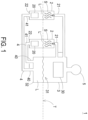
- FIG. 1 is a schematic block diagram illustrating an immersion cooling system according to an embodiment of the present disclosure.
- an immersion cooling system 1 includes a cooling liquid L, a plurality of server boxes 2, a cooling tank 3 and a plurality of liquid connecting pipes 4.
- a part of the cooling liquid L is contained in the plurality of server boxes 2, and the other part of the cooling liquid L is contained in the cooling tank 3.
- Each of the plurality of server boxes 2 includes an electronic device 20.
- the electronic device 20 is immersed in the cooling liquid L in the server box 2.
- a vapor space S is formed in each of the plurality of server boxes 2 above the cooling liquid L, and the vapor space S of each of the plurality of server boxes 2 is connected to the cooling tank 3.
- the electronic device 20 of at least one of the plurality of server boxes 2 generates thermal energy during operation, which causes part of the cooling liquid L evaporates into hot vapor g flowing into the vapor space S.
- the electronic device 20 is for example but not limited to a server.
- each server box 2 is a pressure-sealed box that avoids leakage of the hot vapor g.
- the cooling liquid L is a non-conductive liquid with a boiling point between 50°C and 60°C.
- Each server box 2 further includes a vent hole 21, the vent hole 21 is connected to the cooling tank 3 and is configured to allow the hot vapor g to flow to the cooling tank 3 through the vent hole 21.
- the cooling tank 3 includes a condenser 30 and a storage part 31.
- the condenser 30 condenses the hot vapor g from the server box 2 to form the cooling liquid L.
- the storage part 31 is connected to the condenser 30, and the storage part 31 storages the cooling liquid L from the condenser 30.
- the storage part 31 has a bottom portion 32, and each server box 2 has a bottom portion 22.
- Each of the liquid connecting pipes 4 has a first end 40 and a second end 41. The first end 40 of each of the liquid connecting pipe 4 is connected to the bottom portion 32 of the storage part 31. The second end 41 of each of the liquid connecting pipe 4 is connected to the bottom portion 22 of the corresponding server box 2.
- the bottom portion 32 of the storage part 31 is higher than the bottom portion 22 of every server box 20 relative to the ground, so the cooling liquid L in the storage part 31 flows into the server boxes 2 through the liquid connecting pipes 4.
- the cooling liquid L in the storage part 31 merges with the cooling liquid L in each of the plurality of server boxes 2 through the plurality of liquid connecting pipes 4 to maintain the same liquid level T.
- the liquid level T in the present disclosure is the measured level of the cooling liquid L in the server box 2 and the storage part 31, namely the liquid level T may have a measurement error range. Consequently, the cooling liquid condensed in the storage part can naturally flow back to the server box, and no water pump or valve should be added for controlling the flow of the cooling liquid.
- the immersion cooling system 1 further includes a pressure balancing device 5.
- the pressure balancing device 5 is connected to the cooling tank 3, and is configured to balance the pressure in the cooling tank 3.
- the pressure balancing device 5 may include an inflatable or deflated means such as a balloon or a bellow, but not limited thereto.
- the air pressure balancing device 5 adjusts the air pressure in the cooling tank 3 through inflation or deflation of the balloon or the bellow. For example, when the rate of generating the hot vapor g by the server box 2 is too high, the condenser 30 of the cooling tank 3 cannot condense the hot vapor g in time, such that the hot vapor g is accumulated in the cooling tank 3, resulting in excessive air pressure in the cooling tank 3. Under such circumstance, in the pressure balancing device 5, the air pressure in the cooling tank 3 can be adjusted through the inflation of the balloon or the bellow, so as to prevent the cooling tank 3 from being deformed and damaged.
- the immersion cooling system 1 shown in FIG. 1 can be further used in a server cabinet.
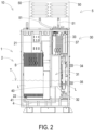
- FIG. 2 is a side view illustrating the immersion cooling system used in a server cabinet according to another embodiment of the present disclosure.
- the immersion cooling system 1 is used in a server cabinet 10
- the air pressure balancing device 5 of the immersion cooling system 1 includes a bellow 50 and a connecting pipe 51 connected thereto.
- an amount of the bellow 50 is not limited to one, and an amount of the corresponding connecting pipe 51 is not limited to one, either.
- the connecting pipe 51 is connected to the cooling tank 3.
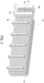
- FIG. 3 is a schematic perspective view illustrating the condenser of the immersion cooling system of FIG. 2 .
- the condenser 30 includes a first condensing pipe 36, a second condensing pipe 37, a plurality of copper pipes 33 which are bent and wound, a hot water output pipe 34 and a cooling water input pipe 35.
- the first condensing pipe 36 is connected to a first end 331 of each of the plurality of copper pipes 33.
- the second condensing pipe 37 is connected to a second end 332 of each of the plurality of copper pipes 33.
- the first condensing pipe 36 and the second condensing pipe 37 are connected to the hot water output pipe 34 and the cooling water input pipe 35, respectively.
- the cooling water input pipe 35 is further connected to an external cooling tower (not shown), and the cooling tower supplies cooling water (or other condensed liquid) to the condenser 30 via the cooling water input pipe 35.
- the cooling water is injected into the second condensing pipe 37 through the cooling water input pipe 35 (as depicted by the dashed arrow in FIG. 2 ).
- the cooling water flows into the plurality of copper pipes 33 through the second condensing pipe 37, an outer wall of the copper pipe 33 is cooled down by the flowing cooling water. Accordingly, the hot vapor g from the server box 2 condenses into the cooling liquid L when the hot vapor g contacts the outer wall of the copper pipe 33.
- the condenser 3 further includes a plurality of mounting brackets 38 connected to the plurality of copper pipes 33.
- the mounting bracket 38 is configured to fix the condenser 3 in the cooling tank 3.
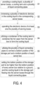
- FIG. 4 is a schematic flow chart illustrating a cooling method of the immersion cooling system according to an embodiment of the present disclosure.
- the cooling method of the immersion cooling system of the present disclosure is applicable for the immersion cooling system 1 stated above.
- the cooling method of the immersion cooling system includes steps S1, S2, S3, S4, S5 and S6.
- a cooling liquid L, a plurality of server boxes 2, a cooling tank 3 and a plurality of liquid connecting pipes 4 are provided in the step S1, a cooling liquid L, a plurality of server boxes 2, a cooling tank 3 and a plurality of liquid connecting pipes 4 are provided.
- a part of the cooling liquid L is contained in the plurality of server boxes 2, and the other part of the cooling liquid L is contained in the cooling tank 3.
- the cooling tank 3 is connected to the plurality of server boxes 2 and the plurality of liquid connecting pipes 4.
- a plurality of electronic devices 20 are immersed in the cooling liquid L in the plurality of server boxes 2, respectively.
- a vapor space S is formed in each of the plurality of server boxes 2 above the cooling liquid L, and the vapor space S of each of the plurality of server boxes 2 is connected to the cooling tank 3.
- the electronic device 20 of at least one of the plurality of server boxes 2 is operated.
- the electronic device 20 of at least one of the plurality of server boxes 2 generates thermal energy during operation, which causes part of the cooling liquid L evaporates into hot vapor g flowing into the vapor space S.
- the condenser 30 of the cooling tank 3 condenses the hot vapor g from the server box 2 to form the cooling liquid L.
- the cooling liquid L flows into the storage part 31 of the cooling tank 3 through the plurality of copper pipes 33 of the condenser 30.
- the bottom portion 32 of the storage part 31 is connected to the bottom portion 22 of each server box 2 through the plurality of liquid connecting pipes 4.
- the bottom portion 32 of the storage part 31 is set to be higher than the bottom portion 22 of every server box 20 relative to the ground, so the cooling liquid L in the storage part 31 flows into the server boxes 2 through the liquid connecting pipes 4.
- the cooling liquid L in the storage part 31 merges with the cooling liquid L in each of the plurality of server boxes 2 through the plurality of liquid connecting pipes 4 to maintain the same liquid level T.
- the cooling method of the immersion cooling system of the present disclosure further includes a step of providing a pressure balancing device 5.
- the pressure balancing device 5 is connected to the cooling tank 3 and is configured to balance the pressure in the cooling tank 3.
- the cooling method of the immersion cooling system of the present disclosure further includes steps of: increasing an amount of the plurality of electronic devices 20 for increasing the hot vapor g being received by the condenser 30 and increasing the pressure in the cooling tank 3; and utilizing the pressure balancing device 5 connected to the cooling tank 3 to absorb the hot vapor g in the cooling tank 3 and to be inflated for maintaining the pressure in the cooling tank 3 within a constant pressure range.
- the cooling method of the immersion cooling system of the present disclosure further includes steps of: decreasing the amount of the plurality of electronic devices 20 for decreasing the hot vapor g being received by the condenser 30 and decreasing the pressure in the cooling tank 3; utilizing the pressure balancing device 5 to vent the vapor in the pressure balancing device 5 to the cooling tank 3 and to be deflated for maintaining the pressure in the cooling tank 3 within a constant pressure range.
- the present disclosure provides an immersion cooling system and a cooling method thereof.
- the cooling liquid in the server box and the cooling liquid in the storage part are merged together through the liquid connecting pipe to maintain the same liquid level.
- the cooling liquid condensed in the storage part can naturally flow back to the server box, and no water pump or valve should be added for controlling the flow of the cooling liquid.
Landscapes
- Engineering & Computer Science (AREA)
- Microelectronics & Electronic Packaging (AREA)
- Physics & Mathematics (AREA)
- Thermal Sciences (AREA)
- Computer Hardware Design (AREA)
- General Engineering & Computer Science (AREA)
- Cooling Or The Like Of Electrical Apparatus (AREA)
Abstract
The present disclosure provides an immersion cooling system (1) for a server cabinet (10) including a plurality of server boxes (2), a cooling tank (3) and a plurality of liquid connecting pipes (4). Each server box (2) includes an electronic device (20) immersed in the cooling liquid (L), and the electronic device (20) generates a thermal energy so that part of the cooling liquid (L) evaporates into a hot vapor (g). The cooling tank (3) is connected to the plurality of server boxes (2) and includes a condenser (30) and a storage part (31). The condenser (30) is connected to each server box (2) and condenses the hot vapor (g) to form the cooling liquid (L). The storage part (31) storages the cooling liquid (L) from the condenser (30). Two ends of the liquid connecting pipe (4) is connected to the storage part (31) and the server box (2) respectively. The cooling liquid (L) in the storage part and the cooling liquid (L) of each server box (2) are maintained in a same liquid level (T).
Description
- The present disclosure relates to a cooling system and a cooling method thereof, and more particularly to an immersion cooling system and a cooling method thereof.
- With the rapid development of 5th Generation mobile networks (5G), artificial intelligence, metaverse and other technologies that require high-speed computing, the requirements for heat dissipation of electronic components are getting higher. In addition, the consumed energy during the heat dissipation process is also emphasized.
- One of the conventional ways to dissipate heat from the electronic components is to utilize the high-speed rotation of the fan to generate air convection, so as to remove the heat energy generated by the electronic components. However, the heat dissipation method that utilizes air convection to remove hot air cannot save energy, and also creates huge sound pollution. On the other hand, if the electronic components are immersed in the cooling liquid for cooling, the cooling liquid is evaporated into vapor so as to remove the heat energy generated by the electronic components, then the vapor will be condensed back to the cooling liquid according to the condensation technology. Under such circumstance, a water pump or valve should be added to control the liquid flow between the condensed cooling liquid and the cooling liquid soaking electronic components.
- Therefore, there is a need of providing an immersion cooling system and a cooling method thereof to obviate the drawbacks encountered from the prior arts.
- It is an objective of the present disclosure to provide an immersion cooling system and a cooling method thereof. The cooling liquid in the server box and the cooling liquid in the storage part are merged together through the liquid connecting pipe to maintain the same liquid level. Thereby, the cooling liquid condensed in the storage part can naturally flow back to the server box, and no water pump or valve should be added for controlling the flow of the cooling liquid.
- In accordance with an aspect of the present disclosure, an immersion cooling system for a server cabinet is provided. The immersion cooling system includes a plurality of server boxes, a cooling tank and a plurality of liquid connecting pipes. Each of the plurality of server boxes has a cooling liquid, and each of the plurality of server boxes includes an electronic device immersed in the cooling liquid, the electronic device of at least one of the plurality of server boxes generates a thermal energy during the operation of the electronic device so that a part of the cooling liquid evaporates into a hot vapor. The cooling tank is connected to the plurality of server boxes and includes a condenser and a storage part. The condenser is connected to a vent hole of each of the plurality of server boxes, wherein the condenser condenses the hot vapor from the server box to form the cooling liquid. The storage part is connected to the condenser, wherein the storage part storages the cooling liquid from the condenser. A first end of each of the plurality of liquid connecting pipes is connected to a bottom portion of the storage part, and a second end of each of the plurality of liquid connecting pipes is connected to a bottom portion of the corresponding server box. The cooling liquid in the storage part flows into each of the plurality of server boxes through each of the plurality of liquid connecting pipes. The cooling liquid in the storage part and the cooling liquid in each of the plurality of server boxes are maintained in a same liquid level.
- In accordance with an aspect of the present disclosure, a cooling method of the immersion cooling system is provided. The cooling method of the immersion cooling system includes steps of: providing a cooling liquid, a plurality of server boxes, a cooling tank and a plurality of liquid connecting pipes, wherein a part of the cooling liquid is contained in the plurality of server boxes, and the other part of the cooling liquid is contained in the cooling tank, the cooling tank is connected to the plurality of server boxes and the plurality of liquid connecting pipes; immersing a plurality of electronic devices in the cooling liquid in the corresponding server boxes, wherein each of the plurality of server boxes further includes a vapor space disposed above the cooling liquid, and the vapor space of each of the plurality of server boxes is connected to the cooling tank; operating the electronic device of at least one of the plurality of server boxes, wherein the electronic device of at least one of the plurality of server boxes generates a thermal energy during operation, which causes a part of the cooling liquid evaporates into hot vapor, and the hot vapor flows into the vapor space; utilizing a condenser of the cooling tank to condense the hot vapor from the server box to form the cooling liquid, wherein the cooling liquid flows into a storage part of the cooling tank through a plurality of copper pipes of the condenser; and utilizing the plurality of liquid connecting pipes to connect a bottom portion of the storage part and a bottom portion of each of the plurality of server boxes, and the cooling liquid in the storage part flowing into each of the plurality of server boxes through each of the plurality of liquid connecting pipes, wherein the cooling liquid in the storage part and the cooling liquid in each of the plurality of server boxes are maintained a same liquid level.
- The above contents of the present invention will become more readily apparent to those ordinarily skilled in the art after reviewing the following detailed description and accompanying drawings, in which:
-
-
FIG. 1 is a schematic block diagram illustrating an immersion cooling system according to an embodiment of the present disclosure; -
FIG. 2 is a side view illustrating an immersion cooling system used in a server cabinet according to another embodiment of the present disclosure; -
FIG. 3 is a schematic perspective view illustrating the condenser of the immersion cooling system ofFIG. 2 ; and -
FIG. 4 is a schematic flow chart illustrating a cooling method of the immersion cooling system according to an embodiment of the present disclosure. - The present disclosure will now be described more specifically with reference to the following embodiments. It is to be noted that the following descriptions of preferred embodiments of this disclosure are presented herein for purpose of illustration and description only. It is not intended to be exhaustive or to be limited to the precise form disclosed.
-
FIG. 1 is a schematic block diagram illustrating an immersion cooling system according to an embodiment of the present disclosure. As shown inFIG. 1 , animmersion cooling system 1 includes a cooling liquid L, a plurality ofserver boxes 2, a cooling tank 3 and a plurality of liquid connectingpipes 4. A part of the cooling liquid L is contained in the plurality ofserver boxes 2, and the other part of the cooling liquid L is contained in the cooling tank 3. Each of the plurality ofserver boxes 2 includes anelectronic device 20. Theelectronic device 20 is immersed in the cooling liquid L in theserver box 2. A vapor space S is formed in each of the plurality ofserver boxes 2 above the cooling liquid L, and the vapor space S of each of the plurality ofserver boxes 2 is connected to the cooling tank 3. Theelectronic device 20 of at least one of the plurality ofserver boxes 2 generates thermal energy during operation, which causes part of the cooling liquid L evaporates into hot vapor g flowing into the vapor space S. Theelectronic device 20 is for example but not limited to a server. It should be noted that eachserver box 2 is a pressure-sealed box that avoids leakage of the hot vapor g. In an embodiment, the cooling liquid L is a non-conductive liquid with a boiling point between 50°C and 60°C. Eachserver box 2 further includes avent hole 21, thevent hole 21 is connected to the cooling tank 3 and is configured to allow the hot vapor g to flow to the cooling tank 3 through thevent hole 21. The cooling tank 3 includes acondenser 30 and astorage part 31. Thecondenser 30 condenses the hot vapor g from theserver box 2 to form the cooling liquid L. Thestorage part 31 is connected to thecondenser 30, and thestorage part 31 storages the cooling liquid L from thecondenser 30. Thestorage part 31 has abottom portion 32, and eachserver box 2 has abottom portion 22. Each of theliquid connecting pipes 4 has afirst end 40 and asecond end 41. Thefirst end 40 of each of the liquid connectingpipe 4 is connected to thebottom portion 32 of thestorage part 31. Thesecond end 41 of each of theliquid connecting pipe 4 is connected to thebottom portion 22 of thecorresponding server box 2. Thebottom portion 32 of thestorage part 31 is higher than thebottom portion 22 of everyserver box 20 relative to the ground, so the cooling liquid L in thestorage part 31 flows into theserver boxes 2 through the liquid connectingpipes 4. The cooling liquid L in thestorage part 31 merges with the cooling liquid L in each of the plurality ofserver boxes 2 through the plurality of liquid connectingpipes 4 to maintain the same liquid level T. It should be noted that the liquid level T in the present disclosure is the measured level of the cooling liquid L in theserver box 2 and thestorage part 31, namely the liquid level T may have a measurement error range. Consequently, the cooling liquid condensed in the storage part can naturally flow back to the server box, and no water pump or valve should be added for controlling the flow of the cooling liquid. - In an embodiment, the
immersion cooling system 1 further includes apressure balancing device 5. Thepressure balancing device 5 is connected to the cooling tank 3, and is configured to balance the pressure in the cooling tank 3. Thepressure balancing device 5 may include an inflatable or deflated means such as a balloon or a bellow, but not limited thereto. In an embodiment, the airpressure balancing device 5 adjusts the air pressure in the cooling tank 3 through inflation or deflation of the balloon or the bellow. For example, when the rate of generating the hot vapor g by theserver box 2 is too high, thecondenser 30 of the cooling tank 3 cannot condense the hot vapor g in time, such that the hot vapor g is accumulated in the cooling tank 3, resulting in excessive air pressure in the cooling tank 3. Under such circumstance, in thepressure balancing device 5, the air pressure in the cooling tank 3 can be adjusted through the inflation of the balloon or the bellow, so as to prevent the cooling tank 3 from being deformed and damaged. - In an embodiment, the
immersion cooling system 1 shown inFIG. 1 can be further used in a server cabinet. As shown inFIG. 2, FIG. 2 is a side view illustrating the immersion cooling system used in a server cabinet according to another embodiment of the present disclosure. In this embodiment, theimmersion cooling system 1 is used in aserver cabinet 10, and the airpressure balancing device 5 of theimmersion cooling system 1 includes abellow 50 and a connectingpipe 51 connected thereto. In an embodiment, an amount of thebellow 50 is not limited to one, and an amount of the corresponding connectingpipe 51 is not limited to one, either. The connectingpipe 51 is connected to the cooling tank 3. When the air pressure in the cooling tank 3 is too high, in the airpressure balancing device 5, part of the hot vapor g in the cooling tank 3 flows into thebellow 50 through the connectingpipe 51 to be absorbed by theinflatable bellow 50, thereby adjusting the air pressure in the cooling tank 3. - Please refer to
FIGs. 2 and3. FIG. 3 is a schematic perspective view illustrating the condenser of the immersion cooling system ofFIG. 2 . In this embodiment, thecondenser 30 includes afirst condensing pipe 36, asecond condensing pipe 37, a plurality ofcopper pipes 33 which are bent and wound, a hotwater output pipe 34 and a coolingwater input pipe 35. Thefirst condensing pipe 36 is connected to afirst end 331 of each of the plurality ofcopper pipes 33. Thesecond condensing pipe 37 is connected to asecond end 332 of each of the plurality ofcopper pipes 33. Thefirst condensing pipe 36 and thesecond condensing pipe 37 are connected to the hotwater output pipe 34 and the coolingwater input pipe 35, respectively. In addition, the coolingwater input pipe 35 is further connected to an external cooling tower (not shown), and the cooling tower supplies cooling water (or other condensed liquid) to thecondenser 30 via the coolingwater input pipe 35. The cooling water is injected into thesecond condensing pipe 37 through the cooling water input pipe 35 (as depicted by the dashed arrow inFIG. 2 ). The cooling water flows into the plurality ofcopper pipes 33 through thesecond condensing pipe 37, an outer wall of thecopper pipe 33 is cooled down by the flowing cooling water. Accordingly, the hot vapor g from theserver box 2 condenses into the cooling liquid L when the hot vapor g contacts the outer wall of thecopper pipe 33. At the same time, the heat energy lost from the hot vapor g during the condensation process is conducted inside of thecopper pipe 33 to heat up the cooling water and turn it into hot water. The hot water is vented through thefirst condensing pipe 36 and the hot water output pipe 34 (as depicted by the solid arrow inFIG. 2 ). In an embodiment, the condenser 3 further includes a plurality of mounting brackets 38 connected to the plurality ofcopper pipes 33. The mounting bracket 38 is configured to fix the condenser 3 in the cooling tank 3. -
FIG. 4 is a schematic flow chart illustrating a cooling method of the immersion cooling system according to an embodiment of the present disclosure. The cooling method of the immersion cooling system of the present disclosure is applicable for theimmersion cooling system 1 stated above. As shown inFIG. 4 , the cooling method of the immersion cooling system includes steps S1, S2, S3, S4, S5 and S6. In the step S1, a cooling liquid L, a plurality ofserver boxes 2, a cooling tank 3 and a plurality of liquid connectingpipes 4 are provided. A part of the cooling liquid L is contained in the plurality ofserver boxes 2, and the other part of the cooling liquid L is contained in the cooling tank 3. The cooling tank 3 is connected to the plurality ofserver boxes 2 and the plurality of liquid connectingpipes 4. In the step S2, a plurality ofelectronic devices 20 are immersed in the cooling liquid L in the plurality ofserver boxes 2, respectively. A vapor space S is formed in each of the plurality ofserver boxes 2 above the cooling liquid L, and the vapor space S of each of the plurality ofserver boxes 2 is connected to the cooling tank 3. In the step S3, theelectronic device 20 of at least one of the plurality ofserver boxes 2 is operated. Theelectronic device 20 of at least one of the plurality ofserver boxes 2 generates thermal energy during operation, which causes part of the cooling liquid L evaporates into hot vapor g flowing into the vapor space S. In the step S4, thecondenser 30 of the cooling tank 3 condenses the hot vapor g from theserver box 2 to form the cooling liquid L. The cooling liquid L flows into thestorage part 31 of the cooling tank 3 through the plurality ofcopper pipes 33 of thecondenser 30. In the step S5, thebottom portion 32 of thestorage part 31 is connected to thebottom portion 22 of eachserver box 2 through the plurality of liquid connectingpipes 4. In the step S6, thebottom portion 32 of thestorage part 31 is set to be higher than thebottom portion 22 of everyserver box 20 relative to the ground, so the cooling liquid L in thestorage part 31 flows into theserver boxes 2 through theliquid connecting pipes 4. The cooling liquid L in thestorage part 31 merges with the cooling liquid L in each of the plurality ofserver boxes 2 through the plurality of liquid connectingpipes 4 to maintain the same liquid level T. - In an embodiment, the cooling method of the immersion cooling system of the present disclosure further includes a step of providing a
pressure balancing device 5. Thepressure balancing device 5 is connected to the cooling tank 3 and is configured to balance the pressure in the cooling tank 3. - In an embodiment, the cooling method of the immersion cooling system of the present disclosure further includes steps of: increasing an amount of the plurality of
electronic devices 20 for increasing the hot vapor g being received by thecondenser 30 and increasing the pressure in the cooling tank 3; and utilizing thepressure balancing device 5 connected to the cooling tank 3 to absorb the hot vapor g in the cooling tank 3 and to be inflated for maintaining the pressure in the cooling tank 3 within a constant pressure range. - In an embodiment, the cooling method of the immersion cooling system of the present disclosure further includes steps of: decreasing the amount of the plurality of
electronic devices 20 for decreasing the hot vapor g being received by thecondenser 30 and decreasing the pressure in the cooling tank 3; utilizing thepressure balancing device 5 to vent the vapor in thepressure balancing device 5 to the cooling tank 3 and to be deflated for maintaining the pressure in the cooling tank 3 within a constant pressure range. - From the above descriptions, the present disclosure provides an immersion cooling system and a cooling method thereof. The cooling liquid in the server box and the cooling liquid in the storage part are merged together through the liquid connecting pipe to maintain the same liquid level. Thereby, the cooling liquid condensed in the storage part can naturally flow back to the server box, and no water pump or valve should be added for controlling the flow of the cooling liquid.
Claims (12)
- An immersion cooling system (1) for a server cabinet (10), characterized by comprising:a plurality of server boxes (2), each having a cooling liquid (L) and comprising an electronic device (20) immersed in the cooling liquid (L), wherein the electronic device (20) of at least one of the plurality of server boxes (2) generates a thermal energy during the operation of the electronic device (20) so that a part of the cooling liquid (L) evaporates into a hot vapor (g);a cooling tank (3) connected to the plurality of server boxes (2), and comprising:a condenser (30) connected to a vent hole (21) of each of the plurality of server boxes (2), wherein the condenser (30) condenses the hot vapor (g) from the server box (2) to form the cooling liquid (L); anda storage part (31) connected to the condenser (30), wherein the storage part (31) storages the cooling liquid (L) from the condenser (30); anda plurality of liquid connecting pipes (4), each having a first end (40) connected to a bottom portion (32) of the storage part (31) and a second end (41) connected to a bottom portion (22) of the corresponding server box (2);wherein the cooling liquid (L) in the storage part (31) flows into each of the plurality of server boxes (2) through each of the plurality of liquid connecting pipes (4),wherein the cooling liquid (L) in the storage part (31) and the cooling liquid (L) in each of the plurality of server boxes (2) are maintained in a same liquid level (T).
- The immersion cooling system (1) according to claim 1, further comprising a pressure balancing device (5), wherein the pressure balancing device (5) is connected to the cooling tank (3) and is configured to balance the pressure in the cooling tank (3).
- The immersion cooling system (1) according to claim 2, wherein the pressure balancing device (5) comprises a balloon or a bellow, and the balloon or the bellow regulates the pressure in the cooling tank (3) through inflation or deflation.
- The immersion cooling system (1) according to claim 1, wherein the cooling liquid (L) is a non-conductive liquid with a boiling point between 50°C and 60°C.
- The immersion cooling system (1) according to claim 1, wherein the condenser (30) comprises a first condensing pipe (36), a second condensing pipe (37), a plurality of copper pipes (33), a hot water output pipe (34) and a cooling water input pipe (35), each of the plurality of copper pipes (33) has a first end (331) and a second end (332), and each of the plurality of copper pipes (33) is bent and wound, the first condensing pipe (36) is connected to the first end (331) of each of the plurality of copper pipes (33), and the second condensing pipe (37) is connected to the second end (332) of each of the plurality of copper pipes (33), and the first condensing pipe (36) and the second condensing pipe (37) are connected to the hot water output pipe (34) and the cooling water input pipe (35), respectively.
- The immersion cooling system (1) according to claim 5, wherein a cooling water is injected into the second condensing pipe (37) through the cooling water input pipe (35), the cooling water flows into the plurality of copper pipes (33) through the second condensing pipe (37), an outer wall of the copper pipe (33) is cooled down by the flowing cooling water, the hot vapor (g) from the server box (2) condenses into the cooling liquid (L) when the hot vapor (g) contacts the outer wall of the copper pipe (33), wherein a heat energy lost from the hot vapor (g) during the condensation process is conducted inside of the copper pipe (33) to heat up the cooling water and turn it into a hot water, and the hot water is vented through the first condensing pipe (36) and the hot water output pipe (34).
- The immersion cooling system (1) according to claim 1, wherein the bottom portion (32) of the storage part (31) is higher than the bottom portion (22) of each of the plurality of server boxes (2) relative to the ground so the cooling liquid (L) in the storage part (31) flows into each of the plurality of server boxes (2) through each of the plurality of liquid connecting pipes (4).
- A cooling method of an immersion cooling system (1), characterized by comprising steps of:providing a cooling liquid (L), a plurality of server boxes (2), a cooling tank (3) and a plurality of liquid connecting pipes (4), wherein a part of the cooling liquid (L) is contained in the plurality of server boxes (2), and the other part of the cooling liquid (L) is contained in the cooling tank (3), the cooling tank (3) is connected to the plurality of server boxes (2) and the plurality of liquid connecting pipes (4);immersing a plurality of electronic devices (20) in the cooling liquid (L) in the plurality of server boxes (2), respectively, wherein a vapor space (S) is formed in each of the plurality of server boxes (2) above the cooling liquid (L), and the vapor space (S) of each of the plurality of server boxes (2) is connected to the cooling tank (3);operating the electronic device (20) of at least one of the plurality of server boxes (2), wherein the electronic device (20) of at least one of the plurality of server boxes (2) generates a thermal energy during operation, which causes a part of the cooling liquid (L) evaporates into a hot vapor (g), and the hot vapor (g) flows into the vapor space (S);utilizing a condenser (30) of the cooling tank (3) to condense the hot vapor (g) from the server box (2) to form the cooling liquid (L), wherein the cooling liquid (L) flows into a storage part (31) of the cooling tank (3) through a plurality of copper pipes (33) of the condenser (30); andutilizing the plurality of liquid connecting pipes (4) to connect a bottom portion (32) of the storage part (31) and a bottom portion (22) of each of the plurality of server boxes (2), and the cooling liquid (L) in the storage part (31) flowing into each of the plurality server boxes (2) through each of the plurality of liquid connecting pipes (4),wherein the cooling liquid (L) in the storage part (31) and the cooling liquid (L) in each of the plurality of server boxes (2) are maintained in a same liquid level (T).
- The cooling method according to claim 8, further comprising a step of providing a pressure balancing device (5), wherein the pressure balancing device (5) is connected to the cooling tank (3) and is configured to balance the pressure in the cooling tank (3).
- The cooling method according to claim 9, further comprising steps of:increasing an amount of the plurality of electronic devices (20) for increasing the hot vapor (g) being received by the condenser (30) and increasing the pressure in the cooling tank (3); andutilizing the pressure balancing device (5) connected to the cooling tank (3) to absorb the hot vapor (g) in the cooling tank (3) and to be inflated for maintaining the pressure in the cooling tank (3) within a constant pressure range.
- The cooling method according to claim 10, further comprising steps of:decreasing the amount of the plurality of electronic devices (20) for decreasing the hot vapor (g) being received by the condenser (30) and decreasing the pressure in the cooling tank (3); andutilizing the pressure balancing device (5) to vent the vapor in the pressure balancing device (5) to the cooling tank (3) and to be deflated for maintaining the pressure in the cooling tank (3) within the constant pressure range.
- The cooling method according to claim 8, further comprising a step of:
setting the bottom portion (32) of the storage part (31) to be higher than the bottom portion (22) of each of the plurality of server boxes (2) relative to a ground, and the cooling liquid (L) in the storage part (31) flowing into each of the plurality of server boxes (2) through each of the plurality of liquid connecting pipes (4).
Applications Claiming Priority (1)
| Application Number | Priority Date | Filing Date | Title |
|---|---|---|---|
| CN202210574852.6A CN117156789A (en) | 2022-05-24 | 2022-05-24 | Immersion type water cooling system and cooling method thereof |
Publications (1)
| Publication Number | Publication Date |
|---|---|
| EP4284132A1 true EP4284132A1 (en) | 2023-11-29 |
Family
ID=82932561
Family Applications (1)
| Application Number | Title | Priority Date | Filing Date |
|---|---|---|---|
| EP22190308.1A Pending EP4284132A1 (en) | 2022-05-24 | 2022-08-12 | Immersion cooling system and cooling method thereof |
Country Status (3)
| Country | Link |
|---|---|
| US (1) | US12150275B2 (en) |
| EP (1) | EP4284132A1 (en) |
| CN (1) | CN117156789A (en) |
Families Citing this family (2)
| Publication number | Priority date | Publication date | Assignee | Title |
|---|---|---|---|---|
| NO347980B1 (en) * | 2022-09-05 | 2024-06-03 | Orca Connex As | System and method for delivering cooling water to submerged data processing equipment |
| US12414273B2 (en) * | 2023-01-25 | 2025-09-09 | Green Revolution Cooling, Inc. | Immersion cooling reservoir level control |
Citations (5)
| Publication number | Priority date | Publication date | Assignee | Title |
|---|---|---|---|---|
| US20150070846A1 (en) * | 2013-02-01 | 2015-03-12 | Dell Products L.P. | System and Method for Powering Multiple Electronic Devices Operating Within an Immersion Cooling Vessel |
| DE102016219810A1 (en) * | 2015-10-29 | 2017-05-04 | International Business Machines Corporation | Immersion cooling of inserts with swiveling liquid-cooled heat sink |
| US20180020570A1 (en) * | 2016-07-14 | 2018-01-18 | Fujitsu Limited | Liquid immersion bath for electronic device |
| US20190159360A1 (en) * | 2016-07-26 | 2019-05-23 | Fujitsu Limited | Cooling device and electronic device |
| US20200158443A1 (en) * | 2018-11-16 | 2020-05-21 | Inventec (Pudong) Technology Corp. | Cooling device with a pressure adjuster |
Family Cites Families (25)
| Publication number | Priority date | Publication date | Assignee | Title |
|---|---|---|---|---|
| US6646879B2 (en) * | 2001-05-16 | 2003-11-11 | Cray Inc. | Spray evaporative cooling system and method |
| US6536510B2 (en) * | 2001-07-10 | 2003-03-25 | Thermal Corp. | Thermal bus for cabinets housing high power electronics equipment |
| JP3897024B2 (en) * | 2004-02-10 | 2007-03-22 | 日立電線株式会社 | Liquid circulation type cooling system |
| US20140165638A1 (en) * | 2011-08-01 | 2014-06-19 | Nec Corporation | Cooling device and electronic device made therewith |
| US9560794B2 (en) | 2011-11-08 | 2017-01-31 | Panasonic Intellectual Property Management Co., Ltd. | Cooling device for cooling rack-type server, and data center provided with same |
| CN104040278A (en) * | 2012-01-04 | 2014-09-10 | 日本电气株式会社 | Cooling device and electronic equipment using same |
| US9049800B2 (en) * | 2013-02-01 | 2015-06-02 | Dell Products L.P. | Immersion server, immersion server drawer, and rack-mountable immersion server drawer-based cabinet |
| CN104166448A (en) * | 2014-08-20 | 2014-11-26 | 浪潮电子信息产业股份有限公司 | Immersion-type server cooling device |
| US9812243B2 (en) | 2015-04-16 | 2017-11-07 | Hamilton Sundstrand Corporation | Power converters with immersion cooling |
| GB2549946A (en) * | 2016-05-03 | 2017-11-08 | Bitfury Group Ltd | Immersion cooling |
| US10863650B2 (en) * | 2017-04-28 | 2020-12-08 | Dawning Information Industry (Beijing) Co., Ltd | Air-vapor separation method for immersed liquid cooling system and device thereof |
| CN109932018A (en) * | 2017-12-15 | 2019-06-25 | 泽鸿(广州)电子科技有限公司 | Coolant distribution |
| CN110456893A (en) | 2019-07-26 | 2019-11-15 | 天津神为科技有限公司 | A kind of cooling cabinet of enhanced immersion type |
| CN212367777U (en) * | 2019-12-21 | 2021-01-15 | 苏州浪潮智能科技有限公司 | Liquid cooling cabinet of data center |
| TWI756618B (en) * | 2020-01-15 | 2022-03-01 | 緯穎科技服務股份有限公司 | Immersion cooling apparatus |
| TWM619768U (en) | 2020-05-07 | 2021-11-21 | 瑞領科技股份有限公司 | Constant pressure device for three-chamber immersion cooling server |
| CN213991481U (en) * | 2020-11-30 | 2021-08-17 | 天津商业大学 | An immersed data center cabinet cooling system |
| US12453060B2 (en) * | 2021-02-11 | 2025-10-21 | Intel Corporation | Two phase immersion cooling system with useable warmed liquid output |
| CN113093890A (en) * | 2021-04-08 | 2021-07-09 | 大连理工大学 | Two-phase immersed liquid cooling system for blade server of data center |
| TWI799854B (en) * | 2021-05-07 | 2023-04-21 | 緯穎科技服務股份有限公司 | Immersion cooling system, electronic apparatus having the same and pressure adjusting module |
| US12041751B2 (en) * | 2021-07-21 | 2024-07-16 | Delta Electronics, Inc. | Immersion cooling system |
| US12193188B2 (en) * | 2021-07-21 | 2025-01-07 | Delta Electronics, Inc. | Immersion cooling system |
| US11696422B2 (en) * | 2021-08-18 | 2023-07-04 | Baidu Usa Llc | Highly serviceable immersion cooling structural design for servers |
| US20230209781A1 (en) * | 2021-12-23 | 2023-06-29 | Baidu Usa Llc | Distribution and management cooling system for immersion liquid coolant |
| US12144148B2 (en) * | 2022-06-14 | 2024-11-12 | Microsoft Technology Licensing, Llc | Pressure based phase immersion cooling system |
-
2022
- 2022-05-24 CN CN202210574852.6A patent/CN117156789A/en active Pending
- 2022-08-08 US US17/883,197 patent/US12150275B2/en active Active
- 2022-08-12 EP EP22190308.1A patent/EP4284132A1/en active Pending
Patent Citations (5)
| Publication number | Priority date | Publication date | Assignee | Title |
|---|---|---|---|---|
| US20150070846A1 (en) * | 2013-02-01 | 2015-03-12 | Dell Products L.P. | System and Method for Powering Multiple Electronic Devices Operating Within an Immersion Cooling Vessel |
| DE102016219810A1 (en) * | 2015-10-29 | 2017-05-04 | International Business Machines Corporation | Immersion cooling of inserts with swiveling liquid-cooled heat sink |
| US20180020570A1 (en) * | 2016-07-14 | 2018-01-18 | Fujitsu Limited | Liquid immersion bath for electronic device |
| US20190159360A1 (en) * | 2016-07-26 | 2019-05-23 | Fujitsu Limited | Cooling device and electronic device |
| US20200158443A1 (en) * | 2018-11-16 | 2020-05-21 | Inventec (Pudong) Technology Corp. | Cooling device with a pressure adjuster |
Also Published As
| Publication number | Publication date |
|---|---|
| CN117156789A (en) | 2023-12-01 |
| US12150275B2 (en) | 2024-11-19 |
| US20230389231A1 (en) | 2023-11-30 |
Similar Documents
| Publication | Publication Date | Title |
|---|---|---|
| US12150275B2 (en) | Immersion cooling system and cooling method thereof | |
| US12389568B2 (en) | Immersion cooling system that enables increased heat flux at heat-generating components of computing devices | |
| US10206307B2 (en) | Immersion cooling | |
| US12408299B2 (en) | Immersion cooling system and electronic apparatus having the same and pressure adjusting module | |
| US20220248559A1 (en) | Systems and methods for immersion cooling with subcooled spray | |
| JP6137167B2 (en) | Cooling device and cooling system | |
| US20240138112A1 (en) | Systems and methods for immersion cooling with subcooled spray | |
| JPWO2019181972A1 (en) | Cooling device, control method and storage medium | |
| WO2015075916A1 (en) | Electronic apparatus enclosure device and electronic apparatus cooling system | |
| WO2010082875A1 (en) | Heat transfer arrangement and electronic housing comprising a heat transfer arrangement and method of controlling heat transfer | |
| TWI809892B (en) | Immersion water cooling system and method thereof | |
| CN115515371A (en) | Multi-phase change thermal management system for servers | |
| US11378344B2 (en) | Immersion cooling system | |
| US20050274139A1 (en) | Sub-ambient refrigerating cycle | |
| KR20240026462A (en) | Hybrid motherboard cooling system for air-cooled servers | |
| CN115315135B (en) | Electronic devices with immersion cooling systems and their operation methods | |
| CN102204423B (en) | Climate control in a radio network node | |
| US20200408467A1 (en) | Two-phase thermal syphon assembly | |
| WO2016031186A1 (en) | Phase-change cooling device, and phase-change cooling method | |
| TWI677663B (en) | Cooling device | |
| JP5340399B2 (en) | System in network node for temperature regulation of electronic equipment | |
| JP2016173216A (en) | Cooling device and electronic device equipped with the same | |
| CN115643736A (en) | Immersion type cooling device and control method thereof |
Legal Events
| Date | Code | Title | Description |
|---|---|---|---|
| PUAI | Public reference made under article 153(3) epc to a published international application that has entered the european phase |
Free format text: ORIGINAL CODE: 0009012 |
|
| STAA | Information on the status of an ep patent application or granted ep patent |
Free format text: STATUS: REQUEST FOR EXAMINATION WAS MADE |
|
| 17P | Request for examination filed |
Effective date: 20230918 |
|
| AK | Designated contracting states |
Kind code of ref document: A1 Designated state(s): AL AT BE BG CH CY CZ DE DK EE ES FI FR GB GR HR HU IE IS IT LI LT LU LV MC MK MT NL NO PL PT RO RS SE SI SK SM TR |
|
| STAA | Information on the status of an ep patent application or granted ep patent |
Free format text: STATUS: EXAMINATION IS IN PROGRESS |
|
| 17Q | First examination report despatched |
Effective date: 20251217 |