EP4283752A2 - Dispositif et procédé de test d'une batterie - Google Patents
Dispositif et procédé de test d'une batterie Download PDFInfo
- Publication number
- EP4283752A2 EP4283752A2 EP23174629.8A EP23174629A EP4283752A2 EP 4283752 A2 EP4283752 A2 EP 4283752A2 EP 23174629 A EP23174629 A EP 23174629A EP 4283752 A2 EP4283752 A2 EP 4283752A2
- Authority
- EP
- European Patent Office
- Prior art keywords
- battery
- fire protection
- interface
- protection hood
- tested
- Prior art date
- Legal status (The legal status is an assumption and is not a legal conclusion. Google has not performed a legal analysis and makes no representation as to the accuracy of the status listed.)
- Withdrawn
Links
Images


Classifications
-
- G—PHYSICS
- G01—MEASURING; TESTING
- G01R—MEASURING ELECTRIC VARIABLES; MEASURING MAGNETIC VARIABLES
- G01R31/00—Arrangements for testing electric properties; Arrangements for locating electric faults; Arrangements for electrical testing characterised by what is being tested not provided for elsewhere
- G01R31/36—Arrangements for testing, measuring or monitoring the electrical condition of accumulators or electric batteries, e.g. capacity or state of charge [SoC]
-
- H—ELECTRICITY
- H01—ELECTRIC ELEMENTS
- H01M—PROCESSES OR MEANS, e.g. BATTERIES, FOR THE DIRECT CONVERSION OF CHEMICAL ENERGY INTO ELECTRICAL ENERGY
- H01M10/00—Secondary cells; Manufacture thereof
- H01M10/42—Methods or arrangements for servicing or maintenance of secondary cells or secondary half-cells
- H01M10/4285—Testing apparatus
-
- G—PHYSICS
- G01—MEASURING; TESTING
- G01R—MEASURING ELECTRIC VARIABLES; MEASURING MAGNETIC VARIABLES
- G01R1/00—Details of instruments or arrangements of the types included in groups G01R5/00 - G01R13/00 and G01R31/00
- G01R1/02—General constructional details
- G01R1/04—Housings; Supporting members; Arrangements of terminals
- G01R1/0408—Test fixtures or contact fields; Connectors or connecting adaptors; Test clips; Test sockets
- G01R1/0416—Connectors, terminals
-
- G—PHYSICS
- G01—MEASURING; TESTING
- G01R—MEASURING ELECTRIC VARIABLES; MEASURING MAGNETIC VARIABLES
- G01R31/00—Arrangements for testing electric properties; Arrangements for locating electric faults; Arrangements for electrical testing characterised by what is being tested not provided for elsewhere
- G01R31/36—Arrangements for testing, measuring or monitoring the electrical condition of accumulators or electric batteries, e.g. capacity or state of charge [SoC]
- G01R31/385—Arrangements for measuring battery or accumulator variables
- G01R31/3865—Arrangements for measuring battery or accumulator variables related to manufacture, e.g. testing after manufacture
-
- H—ELECTRICITY
- H01—ELECTRIC ELEMENTS
- H01M—PROCESSES OR MEANS, e.g. BATTERIES, FOR THE DIRECT CONVERSION OF CHEMICAL ENERGY INTO ELECTRICAL ENERGY
- H01M10/00—Secondary cells; Manufacture thereof
- H01M10/42—Methods or arrangements for servicing or maintenance of secondary cells or secondary half-cells
- H01M10/4228—Leak testing of cells or batteries
-
- H—ELECTRICITY
- H01—ELECTRIC ELEMENTS
- H01M—PROCESSES OR MEANS, e.g. BATTERIES, FOR THE DIRECT CONVERSION OF CHEMICAL ENERGY INTO ELECTRICAL ENERGY
- H01M10/00—Secondary cells; Manufacture thereof
- H01M10/42—Methods or arrangements for servicing or maintenance of secondary cells or secondary half-cells
- H01M10/48—Accumulators combined with arrangements for measuring, testing or indicating the condition of cells, e.g. the level or density of the electrolyte
-
- G—PHYSICS
- G01—MEASURING; TESTING
- G01R—MEASURING ELECTRIC VARIABLES; MEASURING MAGNETIC VARIABLES
- G01R31/00—Arrangements for testing electric properties; Arrangements for locating electric faults; Arrangements for electrical testing characterised by what is being tested not provided for elsewhere
- G01R31/005—Testing of electric installations on transport means
-
- Y—GENERAL TAGGING OF NEW TECHNOLOGICAL DEVELOPMENTS; GENERAL TAGGING OF CROSS-SECTIONAL TECHNOLOGIES SPANNING OVER SEVERAL SECTIONS OF THE IPC; TECHNICAL SUBJECTS COVERED BY FORMER USPC CROSS-REFERENCE ART COLLECTIONS [XRACs] AND DIGESTS
- Y02—TECHNOLOGIES OR APPLICATIONS FOR MITIGATION OR ADAPTATION AGAINST CLIMATE CHANGE
- Y02E—REDUCTION OF GREENHOUSE GAS [GHG] EMISSIONS, RELATED TO ENERGY GENERATION, TRANSMISSION OR DISTRIBUTION
- Y02E60/00—Enabling technologies; Technologies with a potential or indirect contribution to GHG emissions mitigation
- Y02E60/10—Energy storage using batteries
Definitions
- the present invention relates to a device and a method for testing a battery.
- a battery which is also referred to as a traction battery, is used to supply an electric motor or several electric motors with electrical power in order to drive the vehicle in question by means of the electric motor or by means of several electric motors.
- a performance test of the battery takes place, which ensures functionality and functional reliability as part of an end-of-line test.
- the battery being tested is charged and discharged several times in a short period of time.
- the battery can also be exposed to high-voltage voltage for insulation testing.
- the battery If the battery is defective, the battery can catch fire. Such a fire and the associated smoke pose a great danger to the people in the manufacturing environment and the manufacturing facilities and buildings used to manufacture and test the batteries.
- the present invention is based on the technical problem of specifying a device and a method for testing a battery that improve safety when testing a battery.
- the technical problem described above is solved in each case by the independent claims. Further refinements of the invention result from the dependent claims and the description below.
- the invention relates to a device for testing a battery, with a transport system, wherein the transport system is set up to pick up the battery, to transport the battery to a test position and to transport the battery away from the test position, with an interface, wherein the interface is set up to supply the battery arranged in the test position with electrical power and wherein the interface is set up to supply the battery arranged in the test position with gas.
- the device is set up for simultaneous leak testing and performance testing of a battery arranged in the test position, the interface being designed both to supply the battery arranged in the test position with electrical power and to introduce gas into the battery arranged in the test position is set up.
- Simultaneous testing of tightness and performance has the advantage that the gas creates a flame-retardant or fire-retardant atmosphere within the battery, so that the development of fire and smoke can be inhibited in the event of a defect.
- the device has a fire protection hood that can be lowered onto the transport system to shield the battery from the environment.
- the fire protection hood allows the development of fire and smoke to be contained and limited if a battery being tested catches fire during a performance test.
- Such a battery that has caught fire with the fire protection hood lowered onto it or with the fire protection hood lowered onto the transport system can be transported away from the test position using the transport system.
- the battery that has caught fire is transported to an evacuable protective room with a smoke vent or an evacuable protective cell with a smoke vent or to an outdoor area in order to enable the battery to be extinguished and/or burned down in a controlled manner.
- the device according to the invention is in particular a test stand for performance testing or end-of-line testing of a battery.
- a battery it is in particular a traction battery for a motor vehicle, which is intended to supply one or more electric motors of the motor vehicle with electrical power.
- the motor vehicle is in particular a purely electric motor driven motor vehicle or a hybrid vehicle.
- the battery can have one module or multiple modules.
- a module can have several cells or battery cells.
- the method according to the invention and the device according to the invention can be used to test modules or cells, in particular used to test individual modules or cells.
- a battery to be tested itself is not part of the device according to the invention, but is only tested using the device according to the invention.
- the interface for supplying the battery arranged in the test position with electrical power can be provided for both charging and discharging the battery.
- the interface can in particular be intended to supply the battery arranged in the test position, for example, with an electrical power of 1 kW to 500 kW (kilowatt), in particular to supply it with a charging power of from 1 kW to 500 kW (kilowatt).
- the battery can be subjected to up to 7000 volts.
- the fire protection hood can be designed to be automatically lowered.
- a lowering of the fire protection hood is triggered if a control of the device uses one or more sensors to detect a dangerous situation, such as the development of fire and/or smoke.
- the device can therefore have a control that is set up to automatically lower the fire protection hood.
- the lowering of the fire protection hood can be triggered by a machine operator.
- a switching element such as a push button, a switch, a lever or the like, can be provided to manually trigger the lowering of the fire protection hood. If a machine operator detects a dangerous situation, such as a fire and/or smoke, and an automated lowering of the fire protection hood fails or does not take place, the machine operator can trigger the lowering of the fire protection hood by actuating the switching element.
- the fire protection hood viewed in the vertical direction, can be positioned above the test position in a waiting position and can be lowered from the waiting position onto the battery to be tested, which is arranged in the test position, or onto the transport system.
- the fire protection hood viewed in the vertical direction, can be positioned in a waiting position with a lateral offset from the test position and can be lowered from the waiting position onto the battery to be tested, which is arranged in the test position, or onto the transport system.
- the fire protection hood remains in the waiting position. It can therefore be provided that a plurality of batteries are moved one after the other into the test position using the transport system, subjected to a performance test and transported away again using the transport system, without the fire protection hood being lowered.
- the fire protection hood is therefore only used when necessary, ie when there is a dangerous situation. lowered onto the transport system in order to shield the affected battery that has caught fire, which is in the test position, from the environment.
- the fire protection hood can be lowered in a purely linear movement onto the battery to be tested, which is arranged in the test position, or can be lowered onto the transport system. In this way, a cost-effective and efficient design solution can be specified that enables the battery to be quickly shielded or encapsulated from the environment.
- the device can have a handling device, wherein the handling device is set up for automatically lowering and raising the fire protection hood.
- Such a handling device can, for example, have one or more numerically controlled axes or have a robot to hold and move the fire protection hood.
- the handling device can have a coupling for coupling the fire protection hood to the handling device and for decoupling the fire protection hood from the handling device.
- the clutch can be, for example, a mechanical clutch.
- an actuable coupling element such as a latching element, a hook, a pin or the like, is provided on the handling device, which engages in a form-fitting manner in a shaped element or an undercut that is formed on the fire protection hood in order to form the fire protection hood in a form-fitting manner to be coupled with the handling device. It can therefore be provided in particular that the actuable coupling element can be moved from a release position in which the fire protection hood is not coupled to the handling device into a coupling position in which the fire protection hood is positively coupled to the handling device in order to attach the fire protection hood to the handling device to fix or to couple the fire protection hood with the handling device.
- such a handling device alternatively or additionally has a magnetic coupling in order to couple the fire protection hood with the handling device or to decouple the fire protection hood from the handling device.
- the handling device has a gripping device in order to grip the fire protection hood and to raise or lower it.
- a gripping device can be set up to grip the fire protection hood on two or more sides or to grip one or more shaped elements of the fire protection hood on two or more sides in order to raise or lower the fire protection hood.
- the handling device is set up to keep the fire protection hood permanently in the waiting position or the waiting position for the period of this error-free operation.
- the handling device has a support arranged above the test position when viewed in the vertical direction, such as a portal or a cantilever arm, on which an axis of the handling device for lowering and raising the fire protection hood is arranged, the axis being in particular a linear axis.
- the aforementioned structural design enables reliable and cost-effective positioning of the fire protection hood above the test position.
- a linear axis which can be a numerically controlled axis, efficient automation for raising and lowering as well as keeping the fire protection hood in the waiting position can be realized.
- the linear axis can be a pneumatic cylinder.
- the linear axis can be a hydraulic cylinder.
- the linear axis can be a servo-electric spindle drive.
- the fire protection hood can have a fireproof material, be coated with a fireproof material or consist of a fireproof material.
- the fire protection hood can be of skeletal construction and have a frame skeleton with flat filling elements.
- the flat filling elements can also be referred to as fire protection panels or fire protection mats.
- the frame skeleton can be at least partially formed from a metallic material, such as aluminum, aluminum alloys or the like.
- the fire protection panels or fire protection mats can consist of a non-combustible filling material, in particular mineral fire protection material, or of a non-combustible material or have a non-combustible filling material or a non-combustible material.
- the fire protection panels or fire protection mats can be held detachably and interchangeably on the frame skeleton, in particular screwed to the frame skeleton.
- the fire protection hood can be essentially cuboid and have an opening facing the test position.
- the fire protection hood can, for example, have a length of approximately 20 cm to approximately 350 cm, in particular a length of 100 cm - 250 cm.
- the fire protection hood can, for example, have a height of approximately 5 cm to approximately 100 cm, in particular a height of approximately 20 cm to approximately 60 cm.
- the fire protection hood can, for example, have a width of approximately 10 cm to approximately 250 cm, in particular a width of approximately 30 cm to approximately 150 cm.
- the fire protection hood can weigh between approx. 10 kg and approx. 250 kg.
- the fire protection hood can be set up to shield a volume of 0.001 m 3 - 8.75 m 3 from the environment, in particular a volume of 0.5 m 3 - 2.25 m 3 from the environment.
- the overpressure opening can have an overpressure valve.
- the overpressure openings can be formed by a porosity of a material of the fire protection hood, which allows a gas throughput above a certain internal pressure in order to reduce the overpressure.
- the fire protection hood therefore essentially encapsulates the battery from the environment, but allows excess pressure compensation.
- the interface may have a first connection arrangement which is attached to the transport system and the interface may have a second connection arrangement which is connectable to the first connection arrangement, wherein the first connection arrangement is movable relative to the second connection arrangement by means of the transport system.
- the first connection arrangement and the second connection arrangement therefore in particular form the interface, wherein the first connection arrangement and the second connection arrangement in particular have an arrangement of mating contact elements, such as sockets or pins, in order to produce one or more detachable plug connections.
- the first connection arrangement can have two or more sockets, while the second connection arrangement has two or more pins that fit into these sockets, or vice versa, with the connection arrangements each having a mating mating face.
- a battery to be tested is connected to the first connection arrangement via cables or lines before the battery is moved into the test position by means of the transport system.
- the first connection arrangement can be connected to the battery in the area of a side facing away from the second connection arrangement or, as long as the battery is in the test position, is connected to the battery to be tested.
- the battery to be tested can be connected to the first connection arrangement automatically.
- the fire protection hood covers the first connection arrangement in a state lowered onto the transport system and shields it from the environment and the fire protection hood in particular does not cover the second connection arrangement in the state lowered onto the transport system.
- the fire protection hood in this case covers both the first connection arrangement and the battery to be tested.
- test position is specified by a support structure.
- a support structure can, for example, specify a parking position for a transport trolley or a stopping position for a workpiece carrier that is transported over a belt and carries the battery.
- the second connection arrangement of the interface is attached to the support structure.
- the second connection arrangement of the interface is therefore arranged, in particular, in a stationary manner on the support structure, while the first connection arrangement can be moved together with the battery by means of the transport system. If it is said here that the second connection arrangement is positioned in a stationary manner, this does not exclude that the second connection arrangement has actuable or movable components, which, for example, have a lifting movement or actuating movement for automated coupling or decoupling of the interface.
- stationary means that the second connection arrangement with its optionally actuable components remains in the area of the test position or is attached to the support structure in the area of the test position.
- the interface can be automatically coupled and decoupled, with the interface in particular having a mechanical actuator for automated coupling and decoupling of the interface.
- a mechanical actuator can be, for example, an electrically, pneumatically or hydraulically operated lifting cylinder in order to move the first connection arrangement or the second connection arrangement from a separation position in which the first connection arrangement and the second connection arrangement are decoupled from one another into a connection position in which the first connection arrangement and the second connection arrangement are coupled together to move.
- the possibility of automatically coupling or decoupling the interface has the advantage that in the event of danger, a supply of electrical power to the battery can be immediately and automatically disconnected by physically moving the first connection arrangement and the second connection arrangement apart. If the fire protection hood is set up to shield both the battery and the first connection arrangement when lowered onto the transport system, the automated decoupling also enables the fire protection hood to be lowered quickly, provided that the interface is formed in the lowering path of the fire protection hood.
- the mechanical actuator is held on the support structure for automated coupling and decoupling of the interface.
- At least one mechanical lock can be provided in order to lock and/or align the battery to be tested and/or the transport system in the test position.
- the mechanical locking can in particular be able to be coupled and decoupled automatically.
- the mechanical locking can be set up, for example, for positive locking of the battery and/or the transport system and/or for positive positioning of the battery and/or the transport system in the test position.
- an actuator that can do this is set up to engage positively in an undercut or in an opening of the transport system, be attached to the support structure.
- Such an actuating element can be movable from a release position into a locking or centering position, for example by means of an electrically, pneumatically or hydraulically operated lifting cylinder.
- the mechanical locking has two or more adjusting elements.
- the mechanical locking has first positioning elements for fixing the battery and/or the transport system in the test position and that the mechanical locking has second positioning elements for positioning or centering the battery and/or the transport system in the test position.
- the transport system can have a transport trolley.
- the transport trolley can have rollers.
- the transport trolley can have a drive for automatic or semi-automatic movement or movement of the transport trolley.
- a drive for automatic or semi-automatic movement or movement of the transport trolley can be provided that the transport trolley can be moved to and from the test position in a completely automated manner.
- the transport trolley can be moved by an employee using a wired or wireless remote control.
- the transport trolley can be moved manually.
- the transport trolley can have the first connection arrangement.
- the first connection arrangement can in particular be accommodated on a holder of the transport trolley, such as a support plate, a support frame, a support profile or the like.
- the transport trolley can be aligned and locked using the mechanical locking mechanism.
- the transport system has a conveyor belt.
- the transport system has workpiece carriers which are set up to hold a respective battery to be tested, the battery being movable on the conveyor belt by means of an assigned workpiece carrier.
- the interface can have contact elements for establishing an electrically conductive connection, such as a plug connection with a pin and socket or the like.
- the interface has contact elements for establishing a fluid connection, such as a fluid coupling or the like, for introducing gas for leak testing into a battery arranged in the test position, in particular an inert gas, such as helium or the like, for leak testing via the interface can be provided.
- a fluid connection such as a fluid coupling or the like
- an inert gas such as helium or the like
- the interface can be set up to supply power to the battery for a performance test and to supply gas to the battery for a leak test.
- the device is set up for simultaneous leak testing and performance testing of a battery arranged in the test position, the interface being designed both to supply the battery arranged in the test position with electrical power and to introduce gas into the battery arranged in the test position is set up.
- Simultaneous testing of tightness and performance has the advantage that the gas creates a flame-retardant or fire-retardant atmosphere within the battery, so that the development of fire and smoke can be inhibited in the event of a defect.
- a temperature sensor can be provided for monitoring a temperature of the battery to be tested, the temperature sensor being provided in particular for monitoring a temperature inside the battery to be tested.
- a smoke gas sensor can be provided to monitor smoke development from a battery to be tested.
- the aforementioned sensors are used to monitor the battery during performance testing, i.e. H. while charging and/or discharging the battery, and/or during a high-voltage test.
- the fire protection hood can be lowered automatically depending on a signal from the temperature sensor and/or the smoke gas sensor.
- a drive and a coupling element which are provided as part of a handling device for holding and moving the fire protection hood, can be controlled by means of a controller based on the signals from the aforementioned sensors. If, for example, a threshold value for a temperature of the battery, in particular inside the battery, is exceeded, the lowering of the fire protection hood can be initiated by means of the handling device. This applies equally if, alternatively or additionally, for example, an exceeding of a threshold value for a smoke gas concentration is detected by the smoke gas sensor.
- the fire protection hood After the fire protection hood has been lowered onto the transport system, the fire protection hood is decoupled and removal of the battery from the test position can also be triggered automatically using the control.
- the interface and/or a lock can be released automatically by means of the control, for example in order to completely mechanically decouple a transport trolley of the transport system from a support structure, for example.
- the interface has contact elements for establishing a fluid connection, such as a fluid coupling or the like, for introducing cooling medium into a cooling circuit of the battery arranged in the test position.
- the battery can therefore be tempered during a test process.
- the interface can have a first fluid coupling for introducing a gas and a second fluid coupling for introducing a cooling medium, so that the battery can be filled with gas and supplied with a cooling medium at the same time during a performance test.
- the invention relates to a method for testing a battery, with the method steps: providing the battery to be tested on a transport system; Transporting the battery to a test position using the transport system; Supplying the battery to be tested with electrical power and gas via an interface.
- the battery to be tested is both supplied with electrical power via the interface and filled with a gas, with both a performance test and a leak test of the battery being carried out at the same time.
- the simultaneous leak test together with the performance test has the advantage that a difficult to flammable or fire-retardant atmosphere can be created within the battery by the supplied gas, in particular inert gas, in order to increase the safety of the test procedure and the test environment as a whole .
- the leak test a probe is passed along the battery to detect gas escaping from the battery.
- the leak test is therefore carried out in particular as a so-called sniff test.
- a fire protection hood that can be lowered onto the transport system is provided to shield the battery to be tested from the environment.
- the method has the advantage that the safety of testing a battery can be improved using the fire protection hood.
- the method according to the invention can be carried out using a device according to the invention described above.
- a temperature of the battery to be tested is monitored, in particular a temperature inside the battery is monitored , and/or smoke development from the battery to be tested is monitored, and the fire protection hood is lowered to shield the battery to be tested, provided that a threshold value of the temperature and/or a threshold value of smoke development is exceeded.
- flue gas development and smoke development are used synonymously in this text. If we are talking about a battery or a battery to be tested in the present case, this refers to a battery that is being tested using the device according to the invention or using the method according to the invention.
- the fire protection hood is automatically decoupled from a handling device that carries the fire protection hood after it has been lowered onto the transport system. Both lowering and decoupling can be completely automated.
- the battery is automatically removed from the test position after the fire protection hood has been lowered and decoupled.
- the battery can therefore be encapsulated or shielded from the environment in a completely automated manner and removed from the test position in order to avoid injury to persons or damage to the device or surrounding production facilities or the to avoid the building housing the production facilities.
- the interface is automatically decoupled before lowering the fire protection hood and/or during lowering of the fire protection hood.
- the automated separation of the interface can enable rapid and, in particular, uninterrupted lowering of the fire protection hood onto the transport system in order to shield or encapsulate the battery from an environment as quickly as possible.
- a transport carriage of the transport system is locked and/or aligned by means of a mechanical lock in order to position the battery to be tested in the test position.
- the mechanical locking is automatically decoupled after the fire protection hood has been lowered.
- both the decoupling of the locking mechanism and the decoupling of the interface are carried out completely automatically in order to quickly ensure a complete mechanical decoupling of a transport trolley from, for example, a support structure which carries part of the locking mechanism and a part of the interface. In this way, a battery that has caught fire can be removed quickly.
- the battery to be tested is supplied via the interface with a cooling fluid for cooling the battery.
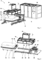
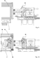
- Fig. 1 shows a device 2 for testing a battery 54.
- the device 2 has a transport system 4 in the form of a transport trolley 4.
- the transport trolley 4 has a footprint 6 for receiving the battery 54 to be tested.
- the transport trolley 4 has a drive system 8 and rollers 10 for automated and/or manual movement of the transport trolley 4.
- the transport trolley 4 is set up to transport the battery 54 to be tested to a test position 12 and to transport the relevant battery 54 to be tested from the test position 12.
- the device 2 has an interface 14, the interface 14 being set up to supply a battery 54 arranged in the test position 12 with electrical power, with a gas or test gas and with a cooling fluid.
- the device 2 has a fire protection hood 16 that can be lowered onto the transport trolley 4 to shield the battery 54 to be tested from an environment U.
- the fire protection hood 16 can be automatically lowered onto the transport trolley 4. For this purpose, the fire protection hood 16 is positioned in a waiting position above the test position 12, viewed in the vertical direction V.
- Fig. 1 shows the fire protection hood 16 in its waiting position.
- the fire protection hood 16 can be lowered onto the transport trolley 4 in a purely linear movement along the vertical direction V.
- the fire protection hood 16 is attached to a handling device 18, the handling device 18 being set up for automatically lowering and raising the fire protection hood 16 and also for holding the fire protection hood 16 in the in Fig. 1 the waiting position shown is set up.
- the handling device 18 has a clutch 20 ( Fig. 6 ) for coupling the fire protection hood 16 with the handling device 18 and for decoupling the fire protection hood 16 from the handling device 18.
- the handling device 18 has a support 22, viewed in the vertical direction V, arranged above the test position 12, on which an axis 24 of the handling device 18 for lowering and raising the fire protection hood 16 is arranged.
- the axis 24 is a linear axis 24 in the form of a pneumatic cylinder 24, which is set up to move the fire protection hood 16 along the vertical direction V.
- the fire protection hood 16 is essentially cuboid-shaped.
- the fire protection hood 16 has an opening 26 facing the test position 12.
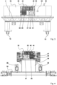
- the interface 14 has a first connection arrangement 28 which is attached to the transport trolley 4.
- the interface 14 has a second connection arrangement 30 which can be connected to the first connection arrangement 28, the first connection arrangement 28 being movable relative to the second connection arrangement 30 by means of the transport carriage 4.
- the test position 12 is specified by a support structure 32.
- the second connection arrangement 30 is attached to the support structure 32.
- the test position 12 of the battery 54 corresponds to a parking position 12 of the transport trolley 4 below the fire protection hood 16, since the battery 54 is positioned by means of the transport trolley 4.
- the support structure 32 has parallel side rails 34 which laterally limit the parking position 12 of the transport trolley 4.
- the support structure 32 has two stops 36, which represent a frontal limitation of a travel path of the transport trolley 4 when entering the parking position 12.
- a mechanical lock 42 is provided on the stops 36, which is designed to align and fix the transport trolley 4 on the support structure 32 ( Fig. 12 ).
- the mechanical lock 42 has one at each stop 26 vertically displaceable locking element 43 for positively locking the transport trolley 4 on the support structure 32 and a horizontally displaceable centering element 41 for positively centering the transport trolley 4 on the support structure 32.
- the locking elements 43 and centering elements 41 each engage in associated shaped elements 37, 39 of the transport trolley 4 .
- the support structure 32 has a holder 38 which carries the second connection arrangement 30 of the interface 14.
- the second connection arrangement 30 is attached to the support structure 32 by means of the holder 38.
- the first connection arrangement 28 is accommodated on a holder 58 of the transport trolley 4.
- the interface 14 can be coupled and decoupled in an automated manner, with the interface 14 having a mechanical actuator 40 for automated coupling and decoupling of the interface 14.
- the mechanical actuator 40 is attached to the holder 38 and is intended to carry out a linear lifting movement in the direction of the transport trolley 4.
- the mechanical actuator 40 therefore carries the second connection arrangement 30 and is intended to move the second connection arrangement 30 in the direction of the first connection arrangement 28 in order to couple them to one another as long as the transport carriage 4 is in the test position 12.
- the interface 14 has contact elements 44 for producing an electrically conductive plug connection.
- the contact elements 44 are used to transmit an electrical charging power or discharging power in the course of a performance test of the battery 54 to be tested.
- the interface 14 has contact elements 46 for establishing a fluid connection for introducing test gas for leak testing.
- the contact elements 46 form a fluid coupling.
- the contact elements 46 are used to introduce gas into the battery 54 to be tested for leak testing.
- the interface 14 has contact elements 47, 49 for establishing a fluid connection for introducing cooling medium for temperature control into the battery 54 to be tested, and namely a flow 47 and a return 49.
- the contact elements 47, 49 each form a fluid coupling.
- the contact elements 47, 49 are used to introduce cooling medium into a cooling circuit of the battery 54 to be tested.
- contact elements 51 of a measuring line contact elements 53 of an auxiliary voltage supply and contact elements 55 of a CAN BUS for transmitting control signals at the interface 14 are provided.
- the device 2 is set up for the simultaneous leak test and performance test of a battery arranged in the test position.
- a temperature sensor 48 is provided for monitoring a temperature inside the battery to be tested and a smoke gas sensor 50 is provided for monitoring smoke development in a battery to be tested.
- the device 2 has a controller 52 which is set up to carry out the performance test and the leak test of the battery 54 to be tested.
- the controller 52 is further set up to lower the fire protection hood 16 onto the transport trolley 4 depending on a signal from the temperature sensor 48 and/or the smoke gas sensor 50.
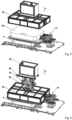
- a first method step (A) the battery 54 to be tested is first provided on the transport trolley 4 ( Fig. 2 ) and connected to the first connection arrangement 28. Connections 57 between the first connection arrangement 28 and the battery 54 are in Fig. 7 and Fig. 8 indicated schematically.
- the battery 54 to be tested is moved into the test position 12 on the transport trolley 4 in a method step (B) ( Fig. 1 , Fig. 5 ).
- the transport trolley 4 is used the mechanical lock 42 aligned or centered and fixed to the support structure 32.
- the interface 14 is then coupled by moving the second connection arrangement 30 from the position according to using the mechanical actuator 40 Fig. 8 is moved in the direction of the first connection arrangement 28, so that a plug connection is formed between the first connection arrangement 28 and the second connection arrangement 30, as in Fig. 7 shown.
- a performance test and a leak test of the battery 54 are carried out simultaneously, the battery 54 being supplied with electrical power via the interface 14 and being filled with gas at the same time. Meanwhile, cooling medium is also introduced via the interface 14.
- the battery 54 is automatically removed from the test position 12 (cf. Fig. 2 ), whereby the interface 12 and the mechanical locking device 42 are decoupled before removal (process step D1).
- the fire protection hood 16 remains permanently in its position Figures 1, 2 and 5 waiting position shown.
- the fire protection hood 16 is lowered onto the transport trolley 4 in order to protect the battery 54 from the environment U to encapsulate or shield ( Fig. 6 , Fig. 9, Fig. 10 ).
- the interface 14 Before and/or during the lowering of the fire protection hood 16, the interface 14 is decoupled. When completely lowered onto the transport trolley 4, the fire protection hood 16 shields both the battery 54 and the first connection arrangement 28 from the environment U ( Fig. 9, Fig. 10 ).
- the fire protection hood 16 After the fire protection hood 16 has been lowered onto the transport trolley 4, the fire protection hood 16 is decoupled from the handling device 18 and also the Locking 42 on the support structure 32 is released or decoupled. There is therefore no longer any mechanical connection between the transport trolley 4 and the support structure 32.
- the transport trolley 4 can transport the battery 54 that has caught fire together with the fire protection hood 16 lowered onto the transport trolley 4 from the test position 12, as exemplified in Fig. 11 shown (process step D2).
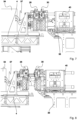
- Fig. 13 shows the fire protection hood 16 in an individual view with an enlarged detail of a connecting piece 56 ( Fig. 14 ) for coupling the fire protection hood 16 with the handling device 18.
- the fire protection hood 16 has a skeletal construction and has a frame skeleton 59 with flat filling elements 61.
- the flat filling elements 61 are fire protection panels.
- the frame skeleton 59 is at least partially made of aluminum or aluminum alloys.
- the fire protection panels 61 have a non-combustible filling material.
- the fire protection panels 61 are detachably and interchangeably held on the frame skeleton 59 and in the present case are screwed to the frame skeleton 59.
Landscapes
- Engineering & Computer Science (AREA)
- Manufacturing & Machinery (AREA)
- Chemical & Material Sciences (AREA)
- Chemical Kinetics & Catalysis (AREA)
- Electrochemistry (AREA)
- General Chemical & Material Sciences (AREA)
- Physics & Mathematics (AREA)
- General Physics & Mathematics (AREA)
- Battery Mounting, Suspending (AREA)
- Secondary Cells (AREA)
- Charge And Discharge Circuits For Batteries Or The Like (AREA)
- Testing Electric Properties And Detecting Electric Faults (AREA)
Applications Claiming Priority (1)
| Application Number | Priority Date | Filing Date | Title |
|---|---|---|---|
| DE102022112996.9A DE102022112996A1 (de) | 2022-05-23 | 2022-05-23 | Vorrichtung und verfahren zur prüfung einer batterie |
Publications (2)
| Publication Number | Publication Date |
|---|---|
| EP4283752A2 true EP4283752A2 (fr) | 2023-11-29 |
| EP4283752A3 EP4283752A3 (fr) | 2024-09-11 |
Family
ID=86497399
Family Applications (1)
| Application Number | Title | Priority Date | Filing Date |
|---|---|---|---|
| EP23174629.8A Withdrawn EP4283752A3 (fr) | 2022-05-23 | 2023-05-22 | Dispositif et procédé de test d'une batterie |
Country Status (4)
| Country | Link |
|---|---|
| US (1) | US20230378553A1 (fr) |
| EP (1) | EP4283752A3 (fr) |
| CN (1) | CN117110872A (fr) |
| DE (1) | DE102022112996A1 (fr) |
Families Citing this family (1)
| Publication number | Priority date | Publication date | Assignee | Title |
|---|---|---|---|---|
| CN118393372B (zh) * | 2024-06-28 | 2024-11-01 | 宁德时代新能源科技股份有限公司 | 电池测试设备及方法 |
Family Cites Families (13)
| Publication number | Priority date | Publication date | Assignee | Title |
|---|---|---|---|---|
| US7505856B2 (en) * | 1999-04-08 | 2009-03-17 | Midtronics, Inc. | Battery test module |
| US6795782B2 (en) * | 1999-04-08 | 2004-09-21 | Midtronics, Inc. | Battery test module |
| CN1196211C (zh) * | 2000-10-25 | 2005-04-06 | 日电东金木有限公司 | 密闭型电池及其制造方法 |
| US7735908B2 (en) * | 2007-07-24 | 2010-06-15 | Gm Global Technology Operations, Inc. | Vehicle hood with sandwich inner structure |
| DE102012106147B4 (de) * | 2012-07-09 | 2015-07-30 | Thyssenkrupp System Engineering Gmbh | Verbindungselement und Verfahren zur elektrischen Kontaktierung eines Kontaktpols einer Batterieeinheit und Prüfstand |
| US10420968B2 (en) * | 2014-09-23 | 2019-09-24 | The Reliable Automatic Sprinkler Co., Inc. | Fire protection sprinkler with a wrench boss detent and a clip, and method of assembling the fire protection sprinkler |
| DE102016112151A1 (de) | 2016-07-04 | 2018-01-04 | Dr. Ing. H.C. F. Porsche Aktiengesellschaft | Prüfvorrichtung und Verfahren zum Löschen eines elektrischen Energiespeichers |
| DE102019101306A1 (de) | 2019-01-18 | 2019-05-02 | FEV Dauerlaufprüfzentrum GmbH | Klimakammer zur Aufnahme einer zu prüfenden Batterieeinheit und zur Konditionierung der Betriebsumgebungsluft der Batterieeinheit und Verfahren zur Prüfung einer Batterieeinheit in konditionierter Betriebsumgebungsluft |
| DE102019115901A1 (de) | 2019-06-12 | 2020-12-17 | Bayerische Motoren Werke Aktiengesellschaft | Batteriezellprüfvorrichtung für zumindest eine Batteriezelle mit einer Gasdruckerfassungseinrichtung sowie Verfahren |
| DE102020111464A1 (de) | 2020-04-27 | 2021-10-28 | Audi Aktiengesellschaft | Verfahren und Anordnung zur Schadenserkennung bei durch Zusammenbau hergestellten Hochvoltbatterien des Akkumulator-Typs |
| DE102020128794A1 (de) | 2020-11-02 | 2022-05-05 | Audi Aktiengesellschaft | Testanordnung und Verfahren zum Testen einer mechanischen Belastbarkeit einer Batteriezelle |
| TWI764440B (zh) * | 2020-12-15 | 2022-05-11 | 國家中山科學研究院 | 電池測試系統安全保護裝置與方法 |
| CN115706277B (zh) * | 2021-08-06 | 2025-11-11 | 上汽通用汽车有限公司 | 一种锂离子电芯的检测方法和系统 |
-
2022
- 2022-05-23 DE DE102022112996.9A patent/DE102022112996A1/de active Pending
-
2023
- 2023-05-22 EP EP23174629.8A patent/EP4283752A3/fr not_active Withdrawn
- 2023-05-23 CN CN202310584064.XA patent/CN117110872A/zh active Pending
- 2023-05-23 US US18/322,139 patent/US20230378553A1/en active Pending
Also Published As
| Publication number | Publication date |
|---|---|
| DE102022112996A1 (de) | 2023-11-23 |
| CN117110872A (zh) | 2023-11-24 |
| US20230378553A1 (en) | 2023-11-23 |
| EP4283752A3 (fr) | 2024-09-11 |
Similar Documents
| Publication | Publication Date | Title |
|---|---|---|
| EP2227349B1 (fr) | Dispositif de protection pour un poste de processus, et procédé de chargement et/ou de déchargement automatique d'un poste de processus | |
| EP3077784B1 (fr) | Ensemble et procédé d'essai de mécanismes de manoeuvre d'aiguilles | |
| DD156552A5 (de) | Einrichtung zur steuerung bzw.ueberwachung von maschinen | |
| DE102019205765A1 (de) | Vorrichtung und Verfahren zur Instandhaltung einer Oberleitungsanlage eines Gleises | |
| DE102012014936A1 (de) | Ladesystem und Verfahren zum elektrischen Aufladen eines Kraftfahrzeugs | |
| AT518902B1 (de) | Brandlöschanlage für einen prüfstand für fahrzeuge | |
| DE102007049221A1 (de) | Fertigungsanlage zum Fertigen von Zusammenbaueinheiten | |
| EP4283752A2 (fr) | Dispositif et procédé de test d'une batterie | |
| EP0137077B1 (fr) | Procédé et dispostif de localisation de chemises défectueuses de barreaux combustibles des réacteurs nucléaires refroidis par eau | |
| DE102023115252A1 (de) | Modulares System zur reversiblen Erzeugung einer Anlage und entsprechende Anlage | |
| WO2008080384A2 (fr) | Procédé pour monter ou démonter des pièces sur des composants de véhicule | |
| EP4283751A2 (fr) | Dispositif et procédé de test d'une batterie | |
| DE3338687C2 (de) | Fernbedienbare Fernhantierungseinrichtung für Großzellen | |
| DE102022205323B4 (de) | Fahrzeugfesselung für einen Prüfstand | |
| WO1999024989A1 (fr) | Machine de chargement permettant de deplacer des objets longs juxtaposes, notamment des elements combustibles | |
| DE102013210154B4 (de) | Vorrichtung zur Erhöhung der Sicherheit beim Gebrauch von Batteriesystemen | |
| WO2026027255A1 (fr) | Appareil et procédé de traitement pour effectuer des opérations de travail de voie | |
| DE102011001718B4 (de) | Prüfvorrichtung für eine lichtabhängige Prüfung eines Photovoltaikmoduls sowie Verfahren zur Prüfung des Photovoltaikmoduls in der Prüfvorrichtung | |
| DE19544240A1 (de) | Verfahren und Vorrichtung zur Ermittlung der räumlichen Koordinaten von Objektpunkten und Verfahren zur Herstellung einer Karosserie | |
| DE102014009862A1 (de) | Anbindungssystem für eine Traktionsbatterie eines Kraftfahrzeugs | |
| EP2687476B1 (fr) | Procédé et dispositif de surveillance de conteneurs de refroidissement dans des terminaux et analogues | |
| EP4605977A1 (fr) | Dispositif et procédé de déplacement d'objets entre deux environnements contrôlés | |
| DE102009049806A1 (de) | Verfahren und Einrichtung zur elektrischen Isolationsprüfung sowie Verfahren und System zur Herstellung von Photovoltaikmodulen | |
| EP3951246A1 (fr) | Chariot de remplissage pour une pluralité de bouteilles de gaz | |
| DE102014200181A1 (de) | Mobile Containereinheit zum Warten und/oder Reparieren von Batteriesystemen und/oder Batteriemodulen, System mit wenigstens einer solchen Containereinheit sowie Verfahren zur Nutzung einer solchen Containereinheit |
Legal Events
| Date | Code | Title | Description |
|---|---|---|---|
| PUAI | Public reference made under article 153(3) epc to a published international application that has entered the european phase |
Free format text: ORIGINAL CODE: 0009012 |
|
| STAA | Information on the status of an ep patent application or granted ep patent |
Free format text: STATUS: THE APPLICATION HAS BEEN PUBLISHED |
|
| AK | Designated contracting states |
Kind code of ref document: A2 Designated state(s): AL AT BE BG CH CY CZ DE DK EE ES FI FR GB GR HR HU IE IS IT LI LT LU LV MC ME MK MT NL NO PL PT RO RS SE SI SK SM TR |
|
| PUAL | Search report despatched |
Free format text: ORIGINAL CODE: 0009013 |
|
| AK | Designated contracting states |
Kind code of ref document: A3 Designated state(s): AL AT BE BG CH CY CZ DE DK EE ES FI FR GB GR HR HU IE IS IT LI LT LU LV MC ME MK MT NL NO PL PT RO RS SE SI SK SM TR |
|
| RIC1 | Information provided on ipc code assigned before grant |
Ipc: G01R 31/385 20190101ALI20240802BHEP Ipc: H01M 10/42 20060101AFI20240802BHEP |
|
| STAA | Information on the status of an ep patent application or granted ep patent |
Free format text: STATUS: THE APPLICATION IS DEEMED TO BE WITHDRAWN |
|
| 18D | Application deemed to be withdrawn |
Effective date: 20250312 |