EP4283341A1 - Lidar device - Google Patents
Lidar device Download PDFInfo
- Publication number
- EP4283341A1 EP4283341A1 EP21927860.3A EP21927860A EP4283341A1 EP 4283341 A1 EP4283341 A1 EP 4283341A1 EP 21927860 A EP21927860 A EP 21927860A EP 4283341 A1 EP4283341 A1 EP 4283341A1
- Authority
- EP
- European Patent Office
- Prior art keywords
- frequency
- optical
- laser beam
- output
- light
- Prior art date
- Legal status (The legal status is an assumption and is not a legal conclusion. Google has not performed a legal analysis and makes no representation as to the accuracy of the status listed.)
- Granted
Links
Images







Classifications
-
- G—PHYSICS
- G01—MEASURING; TESTING
- G01N—INVESTIGATING OR ANALYSING MATERIALS BY DETERMINING THEIR CHEMICAL OR PHYSICAL PROPERTIES
- G01N21/00—Investigating or analysing materials by the use of optical means, i.e. using sub-millimetre waves, infrared, visible or ultraviolet light
- G01N21/17—Systems in which incident light is modified in accordance with the properties of the material investigated
- G01N21/25—Colour; Spectral properties, i.e. comparison of effect of material on the light at two or more different wavelengths or wavelength bands
- G01N21/31—Investigating relative effect of material at wavelengths characteristic of specific elements or molecules, e.g. atomic absorption spectrometry
- G01N21/314—Investigating relative effect of material at wavelengths characteristic of specific elements or molecules, e.g. atomic absorption spectrometry with comparison of measurements at specific and non-specific wavelengths
- G01N21/3151—Investigating relative effect of material at wavelengths characteristic of specific elements or molecules, e.g. atomic absorption spectrometry with comparison of measurements at specific and non-specific wavelengths using two sources of radiation of different wavelengths
-
- G—PHYSICS
- G01—MEASURING; TESTING
- G01S—RADIO DIRECTION-FINDING; RADIO NAVIGATION; DETERMINING DISTANCE OR VELOCITY BY USE OF RADIO WAVES; LOCATING OR PRESENCE-DETECTING BY USE OF THE REFLECTION OR RERADIATION OF RADIO WAVES; ANALOGOUS ARRANGEMENTS USING OTHER WAVES
- G01S17/00—Systems using the reflection or reradiation of electromagnetic waves other than radio waves, e.g. lidar systems
- G01S17/88—Lidar systems specially adapted for specific applications
- G01S17/95—Lidar systems specially adapted for specific applications for meteorological use
-
- G—PHYSICS
- G01—MEASURING; TESTING
- G01N—INVESTIGATING OR ANALYSING MATERIALS BY DETERMINING THEIR CHEMICAL OR PHYSICAL PROPERTIES
- G01N21/00—Investigating or analysing materials by the use of optical means, i.e. using sub-millimetre waves, infrared, visible or ultraviolet light
- G01N21/17—Systems in which incident light is modified in accordance with the properties of the material investigated
- G01N21/25—Colour; Spectral properties, i.e. comparison of effect of material on the light at two or more different wavelengths or wavelength bands
- G01N21/31—Investigating relative effect of material at wavelengths characteristic of specific elements or molecules, e.g. atomic absorption spectrometry
- G01N21/39—Investigating relative effect of material at wavelengths characteristic of specific elements or molecules, e.g. atomic absorption spectrometry using tunable lasers
-
- G—PHYSICS
- G01—MEASURING; TESTING
- G01S—RADIO DIRECTION-FINDING; RADIO NAVIGATION; DETERMINING DISTANCE OR VELOCITY BY USE OF RADIO WAVES; LOCATING OR PRESENCE-DETECTING BY USE OF THE REFLECTION OR RERADIATION OF RADIO WAVES; ANALOGOUS ARRANGEMENTS USING OTHER WAVES
- G01S17/00—Systems using the reflection or reradiation of electromagnetic waves other than radio waves, e.g. lidar systems
- G01S17/02—Systems using the reflection of electromagnetic waves other than radio waves
- G01S17/06—Systems determining position data of a target
- G01S17/08—Systems determining position data of a target for measuring distance only
- G01S17/10—Systems determining position data of a target for measuring distance only using transmission of interrupted, pulse-modulated waves
- G01S17/26—Systems determining position data of a target for measuring distance only using transmission of interrupted, pulse-modulated waves wherein the transmitted pulses use a frequency-modulated or phase-modulated carrier wave, e.g. for pulse compression of received signals
-
- G—PHYSICS
- G01—MEASURING; TESTING
- G01S—RADIO DIRECTION-FINDING; RADIO NAVIGATION; DETERMINING DISTANCE OR VELOCITY BY USE OF RADIO WAVES; LOCATING OR PRESENCE-DETECTING BY USE OF THE REFLECTION OR RERADIATION OF RADIO WAVES; ANALOGOUS ARRANGEMENTS USING OTHER WAVES
- G01S17/00—Systems using the reflection or reradiation of electromagnetic waves other than radio waves, e.g. lidar systems
- G01S17/02—Systems using the reflection of electromagnetic waves other than radio waves
- G01S17/06—Systems determining position data of a target
- G01S17/08—Systems determining position data of a target for measuring distance only
- G01S17/32—Systems determining position data of a target for measuring distance only using transmission of continuous waves, whether amplitude-, frequency-, or phase-modulated, or unmodulated
- G01S17/34—Systems determining position data of a target for measuring distance only using transmission of continuous waves, whether amplitude-, frequency-, or phase-modulated, or unmodulated using transmission of continuous, frequency-modulated waves while heterodyning the received signal, or a signal derived therefrom, with a locally-generated signal related to the contemporaneously transmitted signal
-
- G—PHYSICS
- G01—MEASURING; TESTING
- G01S—RADIO DIRECTION-FINDING; RADIO NAVIGATION; DETERMINING DISTANCE OR VELOCITY BY USE OF RADIO WAVES; LOCATING OR PRESENCE-DETECTING BY USE OF THE REFLECTION OR RERADIATION OF RADIO WAVES; ANALOGOUS ARRANGEMENTS USING OTHER WAVES
- G01S7/00—Details of systems according to groups G01S13/00, G01S15/00, G01S17/00
- G01S7/48—Details of systems according to groups G01S13/00, G01S15/00, G01S17/00 of systems according to group G01S17/00
- G01S7/4802—Details of systems according to groups G01S13/00, G01S15/00, G01S17/00 of systems according to group G01S17/00 using analysis of echo signal for target characterisation; Target signature; Target cross-section
-
- G—PHYSICS
- G01—MEASURING; TESTING
- G01S—RADIO DIRECTION-FINDING; RADIO NAVIGATION; DETERMINING DISTANCE OR VELOCITY BY USE OF RADIO WAVES; LOCATING OR PRESENCE-DETECTING BY USE OF THE REFLECTION OR RERADIATION OF RADIO WAVES; ANALOGOUS ARRANGEMENTS USING OTHER WAVES
- G01S7/00—Details of systems according to groups G01S13/00, G01S15/00, G01S17/00
- G01S7/48—Details of systems according to groups G01S13/00, G01S15/00, G01S17/00 of systems according to group G01S17/00
- G01S7/481—Constructional features, e.g. arrangements of optical elements
- G01S7/4814—Constructional features, e.g. arrangements of optical elements of transmitters alone
-
- G—PHYSICS
- G01—MEASURING; TESTING
- G01S—RADIO DIRECTION-FINDING; RADIO NAVIGATION; DETERMINING DISTANCE OR VELOCITY BY USE OF RADIO WAVES; LOCATING OR PRESENCE-DETECTING BY USE OF THE REFLECTION OR RERADIATION OF RADIO WAVES; ANALOGOUS ARRANGEMENTS USING OTHER WAVES
- G01S7/00—Details of systems according to groups G01S13/00, G01S15/00, G01S17/00
- G01S7/48—Details of systems according to groups G01S13/00, G01S15/00, G01S17/00 of systems according to group G01S17/00
- G01S7/491—Details of non-pulse systems
- G01S7/4912—Receivers
- G01S7/4917—Receivers superposing optical signals in a photodetector, e.g. optical heterodyne detection
-
- G—PHYSICS
- G01—MEASURING; TESTING
- G01N—INVESTIGATING OR ANALYSING MATERIALS BY DETERMINING THEIR CHEMICAL OR PHYSICAL PROPERTIES
- G01N21/00—Investigating or analysing materials by the use of optical means, i.e. using sub-millimetre waves, infrared, visible or ultraviolet light
- G01N21/17—Systems in which incident light is modified in accordance with the properties of the material investigated
- G01N2021/1793—Remote sensing
- G01N2021/1795—Atmospheric mapping of gases
-
- G—PHYSICS
- G01—MEASURING; TESTING
- G01N—INVESTIGATING OR ANALYSING MATERIALS BY DETERMINING THEIR CHEMICAL OR PHYSICAL PROPERTIES
- G01N21/00—Investigating or analysing materials by the use of optical means, i.e. using sub-millimetre waves, infrared, visible or ultraviolet light
- G01N21/17—Systems in which incident light is modified in accordance with the properties of the material investigated
- G01N21/25—Colour; Spectral properties, i.e. comparison of effect of material on the light at two or more different wavelengths or wavelength bands
- G01N21/31—Investigating relative effect of material at wavelengths characteristic of specific elements or molecules, e.g. atomic absorption spectrometry
- G01N21/39—Investigating relative effect of material at wavelengths characteristic of specific elements or molecules, e.g. atomic absorption spectrometry using tunable lasers
- G01N2021/392—Measuring reradiation, e.g. fluorescence, backscatter
-
- G—PHYSICS
- G01—MEASURING; TESTING
- G01N—INVESTIGATING OR ANALYSING MATERIALS BY DETERMINING THEIR CHEMICAL OR PHYSICAL PROPERTIES
- G01N2201/00—Features of devices classified in G01N21/00
- G01N2201/06—Illumination; Optics
- G01N2201/069—Supply of sources
- G01N2201/0696—Pulsed
-
- Y—GENERAL TAGGING OF NEW TECHNOLOGICAL DEVELOPMENTS; GENERAL TAGGING OF CROSS-SECTIONAL TECHNOLOGIES SPANNING OVER SEVERAL SECTIONS OF THE IPC; TECHNICAL SUBJECTS COVERED BY FORMER USPC CROSS-REFERENCE ART COLLECTIONS [XRACs] AND DIGESTS
- Y02—TECHNOLOGIES OR APPLICATIONS FOR MITIGATION OR ADAPTATION AGAINST CLIMATE CHANGE
- Y02A—TECHNOLOGIES FOR ADAPTATION TO CLIMATE CHANGE
- Y02A90/00—Technologies having an indirect contribution to adaptation to climate change
- Y02A90/10—Information and communication technologies [ICT] supporting adaptation to climate change, e.g. for weather forecasting or climate simulation
Definitions
- the present disclosure relates to a lidar device.
- Non-Patent Literature 1 discloses a lidar device that calculates the density of gas present in a space.
- the lidar device includes a first light source that oscillates a first laser beam having a wavelength included in an absorption wavelength band of an observation target gas and a second light source that oscillates a second laser beam having a wavelength not included in the absorption wavelength band.
- the absorption rate of the second laser beam by the gas is lower than the absorption rate of the first laser beam by the gas.
- the gas present in the space corresponds to, for example, a constituent molecule in the air, and the constituent molecule in the air is nitrogen, oxygen, carbon dioxide, or water vapor.
- the constituent molecules in the air also include air pollutants such as nitrogen oxides (NOx).
- the lidar device includes an optical switch, an optical transmission unit, an optical receiving unit, and a density calculating unit.
- the optical switch selects the first laser beam or the second laser beam.
- the optical transmission unit When the optical switch selects the first laser beam, the optical transmission unit emits the first laser beam into the space, and when the optical switch selects the second laser beam, the optical transmission unit emits the second laser beam into the space.
- the optical receiving unit receives first scattered light that is the first laser beam after being emitted by the optical transmission unit and then scattered by the scatterer floating in the space or second scattered light that is the second laser beam after being scattered by the scatterer, and detects interference light between the first scattered light or the second scattered light and the reference light.
- the scatterer corresponds to a cloud, smoke, dust, aerosol, raindrops, or the like.
- the density calculating unit performs frequency analysis on the interference light detected by the optical receiving unit, and calculates the density of the gas from the reception intensity of the analysis result.
- Non-Patent Literature 1 F. Gibert, D. Edouart, C. Cenac ("e” has an acute accent.), F. Le Mounier, and A. Dumas, "2- ⁇ m Ho emitter-based coherent DIAL for CO2 profiling in the atmosphere", Opt. Lett. 40(13), 3093-3096 (2015 ).
- the lidar device in order for the density calculating unit to calculate the density of the gas, the lidar device needs to include a first light source and a second light source.
- the present disclosure has been made to solve the above problems, and an object thereof is to obtain a lidar device capable of calculating the density of gas without including two light sources.
- a lidar device is a lidar device that radiates a first laser beam having a wavelength included in an absorption wavelength band of an observation target gas and a second laser beam having a lower absorption rate by the gas than that of the first laser beam to a space where the gas is present.
- a lidar device includes: a light source to output a laser beam; a frequency output unit to output a first frequency or a second frequency different from the first frequency; a reference light output unit to output the laser beam output from the light source as reference light; an optical transmission unit to generate the first laser beam by modulating an optical frequency of the laser beam output from the light source by the first frequency, generate the second laser beam by modulating the optical frequency of the laser beam output from the light source by the second frequency, and radiate each of the first laser beam and the second laser beam to the space; and an optical receiving unit to receive, as scattered light, the first laser beam radiated by the optical transmission unit and then scattered by a scatterer floating in the space or the second laser beam radiated by the optical transmission unit and then scattered by the scatterer, and detect interference light between the scattered light and the reference light.
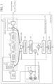
- FIG. 1 is a configuration diagram illustrating a lidar device 1 according to a first embodiment.
- observation target gas a gas that is a gas to be observed
- the lidar device 1 illustrated in FIG. 1 includes a light source 11, a frequency output unit 12, a reference light output unit 13, an optical transmission unit 14, an optical receiving unit 15, and a density calculating unit 16.
- the light source 11 is, for example, a laser that emits and a laser beam of a single frequency, and is implemented by a semiconductor laser, a fiber laser, or a solid-state laser whose emission spectrum has a line width of several MHz or less.
- the light source 11 is implemented by a combination of one or more lasers among a semiconductor laser, a fiber laser, and a solid-state laser.
- the light source 11 outputs the first laser beam that is continuous light to each of the reference light output unit 13 and the optical transmission unit 14.
- the optical frequency of the laser beam output from the light source 11 is f 0 .
- the frequency output unit 12 includes a first frequency oscillator 21, a second frequency oscillator 22, and a frequency mixer 23.
- the frequency output unit 12 outputs a first frequency fi or a second frequency fz different from the first frequency fi to the optical transmission unit 14.
- the first frequency oscillator 21 oscillates a first frequency fi and outputs the first frequency fi to the frequency mixer 23.
- the second frequency oscillator 22 intermittently oscillates a frequency ⁇ f to be added to the first frequency f 1 , and intermittently outputs the frequency ⁇ f to be added to the frequency mixer 23.
- the second frequency oscillator 22 When outputting the frequency ⁇ f to be added to the frequency mixer 23, the second frequency oscillator 22 outputs the frequency ⁇ f to be added to the frequency mixer 40 described later.
- the second frequency oscillator 22 When not outputting the frequency ⁇ f to be added to the frequency mixer 23, the second frequency oscillator 22 does not output the frequency ⁇ f to be added to the frequency mixer 40.
- the frequency mixer 23 is implemented by, for example, a mixer.
- the frequency mixer 23 When the frequency ⁇ f to be added is not output from the second frequency oscillator 22, the frequency mixer 23 outputs the first frequency fi oscillated by the first frequency oscillator 21 to a frequency modulator 32 described later.
- the frequency mixer 23 When the frequency ⁇ f to be added is output from the second frequency oscillator 22, the frequency mixer 23 outputs the frequency fi + ⁇ f, which is the sum of the first frequency fi oscillated by the first frequency oscillator 21 and the frequency ⁇ f to be added, to the optical transmission unit 14 as the second frequency fz.
- the reference light output unit 13 includes an optical distributor 31.
- the reference light output unit 13 outputs the laser beam output from the light source 11 to the optical receiving unit 15 as reference light.
- the optical distributor 31 is implemented by, for example, a beam splitter or a fiber type coupler.
- the optical distributor 31 distributes the laser beam output from the light source 11 at a predetermined ratio.
- the predetermined ratio is, for example, a ratio of 90 on the frequency modulator 32 side and a ratio of 10 on the optical multiplexer 37 side to be described later.
- the optical distributor 31 outputs one of the distributed laser beams to the frequency modulator 32 and outputs the other of the distributed laser beams to the optical multiplexer 37.
- the optical transmission unit 14 includes an optical distributor 31, a frequency modulator 32, a pulse modulator 33, an optical amplifier 34, an optical circulator 35, and an optical antenna 36.
- the optical transmission unit 14 generates a first laser beam by modulating the optical frequency of the laser beam output from the light source 11 by the first frequency f 1 , and radiates the first laser beam into space.
- the first laser beam is laser beam having a first wavelength included in an absorption wavelength band of an observation target gas.
- the optical transmission unit 14 generates a second laser beam by modulating the optical frequency of the laser beam output from the light source 11 by the second frequency f 2 , and radiates the second laser beam into space.
- the second laser beam is a laser beam having a second wavelength not included in the absorption wavelength band of the observation target gas, and has a lower absorption rate by the gas than that of the first laser beam.
- Examples of the gas present in space include constituent molecules in the atmosphere, and examples of the scatterer include clouds, smoke, dust, aerosols, rain drops, and the like.
- the constituent molecule in the atmosphere is nitrogen, oxygen, carbon dioxide, or water vapor.
- the constituent molecules in the air also include air pollutants such as nitrogen oxides (NOx).
- NOx nitrogen oxides
- the absorption wavelength band of the gas is an already-made value.
- the scatterer may be a hard target such as a structure.
- the frequency modulator 32 is implemented by, for example, a modulation element using an acousto-optic element or a modulation element using a lithium niobate crystal.
- the frequency modulator 32 modulates the optical frequency f 0 of the laser beam output from the optical distributor 31 by the first frequency f 1 , and outputs the frequency-modulated laser beam to the pulse modulator 33 as the first laser beam.
- the optical frequency of the first laser beam is f 0 + fi.
- the frequency modulator 32 modulates the optical frequency f 0 of the laser beam output from the optical distributor 31 by the second frequency fz, and outputs the laser beam modulated by the second frequency to the pulse modulator 33 as the second laser beam.
- the optical frequency of the second laser beam is f 0 + f 2 .
- the pulse modulator 33 is implemented by, for example, a modulation element using an acousto-optic element or a modulation element using a lithium niobate crystal, and an optical amplifier such as a semiconductor optical amplifier.
- the pulse modulator 33 pulse-modulates the first laser beam. That is, the pulse modulator 33 converts the first laser beam that is continuous light into pulse light having a predetermined pulse width.
- the pulse modulator 33 outputs the pulse-modulated first laser beam, which is pulse light, to the optical amplifier 34.
- the pulse modulator 33 pulse-modulates the second laser beam. That is, the pulse modulator 33 converts the second laser beam, which is continuous light, into pulse light having a predetermined pulse width.
- the pulse modulator 33 outputs the pulse-modulated second laser beam, which is pulse light, to the optical amplifier 34.
- the optical amplifier 34 When the pulse-modulated first laser beam is output from the pulse modulator 33, the optical amplifier 34 amplifies the pulse-modulated first laser beam and outputs the amplified first laser beam to the optical circulator 35.
- the optical amplifier 34 When the pulse-modulated second laser beam is output from the pulse modulator 33, the optical amplifier 34 amplifies the pulse-modulated second laser beam and outputs the amplified second laser beam to the optical circulator 35.
- the optical circulator 35 is implemented by, for example, a polarization beam splitter and a wavelength plate.
- the optical circulator 35 When the amplified first laser beam is output from the optical amplifier 34, the optical circulator 35 outputs the amplified first laser beam to the optical antenna 36, and outputs scattered light (described later) collected by the optical antenna 36 to the optical multiplexer 37.
- the optical circulator 35 When the amplified second laser beam is output from the optical amplifier 34, the optical circulator 35 outputs the amplified second laser beam to the optical antenna 36, and outputs scattered light collected by the optical antenna 36 to the optical multiplexer 37.
- the optical antenna 36 is implemented by, for example, a plurality of refraction lenses or a plurality of mirrors.
- the optical antenna 36 radiates the first laser beam to a space where gas is present.
- the optical antenna 36 receives scattered light that is the first laser beam scattered by the scatterer floating in the space, and outputs the scattered light to the optical circulator 35.
- the optical antenna 36 radiates the second laser beam to the space where the gas is present.
- the optical antenna 36 receives scattered light that is the second laser beam scattered by the scatterer floating in the space, and outputs the scattered light to the optical circulator 35.
- the optical receiving unit 15 includes an optical circulator 35, an optical antenna 36, an optical multiplexer 37, a balanced detector 38, a frequency discriminator 39, a frequency mixer 40, a signal multiplexer 41, and an analog/digital converter (hereinafter referred to as "A/D converter") 42.
- A/D converter analog/digital converter
- the optical receiving unit 15 receives, as scattered light, the first laser beam after being radiated by the optical transmission unit 14 and then scattered by the scatterer or the second laser beam after being radiated by the optical transmission unit 14 and then scattered by the scatterer.
- the optical receiving unit 15 receives the first laser beam scattered by the scatterer as scattered light when the optical receiving unit 15 radiates the first laser beam into the space, and receives the second laser beam scattered by the scatterer as scattered light when the optical receiving unit 15 radiates the second laser beam into the space.
- the optical receiving unit 15 detects interference light between scattered light and reference light.
- the optical multiplexer 37 is implemented by, for example, a beam splitter or a fiber type coupler.
- the optical multiplexer 37 detects interference light between scattered light output from the optical circulator 35 and reference light output from the optical distributor 31.
- the optical multiplexer 37 outputs the interference light to the balanced detector 38.
- the scattered light is subjected to the Doppler shift, and the optical frequencies f 0 + f 1 and f 0 + fz of the scattered light are shifted. That is, when the lidar device 1 and the scatterer or the like are close to each other, the optical frequencies f 0 + f 1 and f 0 + fz of the scattered light are increased by, for example, the frequency ⁇ f sft . When the lidar device 1 and the scatterer or the like are away from each other, the optical frequencies f 0 + f 1 and f 0 + f 2 of the scattered light are decreased by, for example, the frequency ⁇ f sft .
- the optical multiplexer 37 outputs the interference light having the optical frequency fi + ⁇ f sft to the balanced detector 38 if the scattered light which is the scattered first laser beam is output from the optical circulator 35, and outputs the interference light having the optical frequency f 2 + ⁇ f sft to the balanced detector 38 if the scattered light which is the scattered second laser beam is output from the optical circulator 35.
- the optical multiplexer 37 When the lidar device 1 and the scatterer or the like are away from each other, the optical multiplexer 37 outputs the interference light having the optical frequency fi - ⁇ f sft to the balanced detector 38 if the scattered light which is the scattered first laser beam is output from the optical circulator 35, and outputs the interference light having the optical frequency f 2 - ⁇ f sft to the balanced detector 38 if the scattered light which is the scattered second laser beam is output from the optical circulator 35.
- the optical multiplexer 37 outputs the interference light having the optical frequency fi to the balanced detector 38 if the scattered light that is the scattered first laser beam is output from the optical circulator 35, and outputs the interference light having the optical frequency fz to the balanced detector 38 if the scattered light that is the scattered second laser beam is output from the optical circulator 35.
- the balanced detector 38 is implemented by, for example, a balanced receiver that reduces in-phase noise by using two photodiodes.
- the balanced detector 38 converts the interference light output from the optical multiplexer 37 into an electric signal.
- the balanced detector 38 outputs the electric signal to the frequency discriminator 39.
- the frequency discriminator 39 When the electric signal related to the interference light having the optical frequency f 2 + ⁇ f sft , the electric signal related to the interference light having the optical frequency f 2 - ⁇ f sft , or the electric signal related to the interference light having the optical frequency fz is output from the balanced detector 38, the frequency discriminator 39 outputs these electric signals to the frequency mixer 40.
- the frequency discriminator 39 When the electric signal related to the interference light having the optical frequency f 1 + ⁇ f sft , the electric signal related to the interference light having the optical frequency f 1 - ⁇ f sft , or the electric signal related to the interference light having the optical frequency fi is output from the balanced detector 38, the frequency discriminator 39 outputs these electric signals to the signal multiplexer 41.
- the frequency mixer 40 is implemented by, for example, a mixer.
- the frequency mixer 40 down-converts the frequency of the electric signal output from the frequency discriminator 39 using the frequency ⁇ f to be added output from the second frequency oscillator 22.
- the frequency mixer 40 down-converts the frequency of the electric signal to f 1 + ⁇ f sft using the frequency ⁇ f to be added.
- the frequency mixer 40 When the frequency of the electric signal output from the frequency discriminator 39 is fz - ⁇ f sft , the frequency mixer 40 down-converts the frequency of the electric signal to fi - ⁇ f sft using the frequency ⁇ f to be added.
- the frequency mixer 40 When the frequency of the electric signal output from the frequency discriminator 39 is fz, the frequency mixer 40 down-converts the frequency of the electric signal to fi using the frequency ⁇ f to be added.
- the frequency mixer 40 outputs the down-converted electric signal to the signal multiplexer 41.
- the signal multiplexer 41 Upon receiving the electric signal from the frequency discriminator 39, the signal multiplexer 41 outputs the electric signal to the A/D converter 42.
- the signal multiplexer 41 Upon receiving the electric signal from the frequency mixer 40, the signal multiplexer 41 outputs the electric signal to the A/D converter 42.
- the A/D converter 42 converts an analog electric signal output from the signal multiplexer 41 into a digital signal.
- the A/D converter 42 outputs the digital signal to the density calculating unit 16.
- the density calculating unit 16 analyzes a frequency of the interference light detected by the optical receiving unit 15, and calculates the density of the gas from the analysis result of the frequency.
- the lidar device 1 illustrated in FIG. 1 includes a density calculating unit 16. However, this is merely an example, and the lidar device 1 may not include the density calculating unit 16, and a computer or the like different from the lidar device 1 may implement the density calculating unit 16. In this case, the A/D converter 42 outputs the digital signal to a computer or the like different from the lidar device 1.
- FIG. 2 is a configuration diagram illustrating the density calculating unit 16 of the lidar device 1 according to the first embodiment.
- FIG. 3 is a hardware configuration diagram illustrating hardware of the density calculating unit 16 of the lidar device 1 according to the first embodiment.
- the density calculating unit 16 illustrated in FIG. 2 includes a frequency analysis unit 51, a spectrum intensity calculating unit 52, and a density calculation processing unit 53.
- the frequency analysis unit 51 is implemented by, for example, a frequency analysis circuit 61 illustrated in FIG. 3 .
- the frequency analysis unit 51 converts the digital signal output from the A/D converter 42 into a signal in a frequency domain by performing fast Fourier transform on the digital signal for each predetermined time gate.
- the frequency analysis unit 51 outputs the signal in frequency domain for a plurality of distance ranges to the spectrum intensity calculating unit 52.
- the spectrum intensity calculating unit 52 is implemented by, for example, a spectrum intensity calculating circuit 62 shown in FIG. 3 .
- the spectrum intensity calculating unit 52 calculates the intensity of the reception spectrum for each distance range from the signal in frequency domain for each distance range output from the frequency analysis unit 51.
- the spectrum intensity calculating unit 52 calculates the intensity of the reception spectrum at the frequency fi + ⁇ f sft for each distance range.
- the spectrum intensity calculating unit 52 calculates the intensity of the reception spectrum at the frequency fi - ⁇ f sft for each distance range.
- the spectrum intensity calculating unit 52 calculates the intensity of the reception spectrum at the frequency fi for each distance range.
- the spectrum intensity calculating unit 52 outputs the intensity of the reception spectrum for each distance range to the density calculation processing unit 53.
- the density calculation processing unit 53 is implemented by, for example, a density calculation processing circuit 63 shown in FIG. 3 .
- the density calculation processing unit 53 calculates the density of the gas from the intensity of the reception spectrum for each distance range output from the spectrum intensity calculating unit 52.
- each of the frequency analysis unit 51, the spectrum intensity calculating unit 52, and the density calculation processing unit 53, which are components of the density calculating unit 16, is implemented by dedicated hardware as illustrated in FIG. 3 . That is, it is assumed that the density calculating unit 16 is implemented by the frequency analysis circuit 61, the spectrum intensity calculating circuit 62, and the density calculation processing circuit 63.
- Each of the frequency analysis circuit 61, the spectrum intensity calculating circuit 62, and the density calculation processing circuit 63 corresponds to, for example, a single circuit, a composite circuit, a programmed processor, a parallel-programmed processor, an application specific integrated circuit (ASIC), a field-programmable gate array (FPGA), or a combination thereof.
- ASIC application specific integrated circuit
- FPGA field-programmable gate array
- the components of the density calculating unit 16 are not limited to those implemented by dedicated hardware, and the density calculating unit 16 may be implemented by software, firmware, or a combination of software and firmware.
- the software or firmware is stored in a memory of a computer as a program.
- the computer means hardware that executes a program, and corresponds to, for example, a central processing unit (CPU), a central processing unit, a processing unit, an arithmetic unit, a microprocessor, a microcomputer, a processor, or a digital signal processor (DSP).
- CPU central processing unit
- CPU central processing unit
- processing unit processing unit
- an arithmetic unit a microprocessor
- microcomputer a processor
- DSP digital signal processor
- FIG. 4 is a hardware configuration diagram of a computer in a case where the density calculating unit 16 is implemented by software, firmware, or the like.
- the density calculating unit 16 is implemented by software, firmware, or the like
- a program for causing a computer to execute respective processing procedures in the frequency analysis unit 51, the spectrum intensity calculating unit 52, and the density calculation processing unit 53 is stored in a memory 71.
- a processor 72 of the computer executes the program stored in the memory 71.
- FIG. 3 illustrates an example in which each of the components of the density calculating unit 16 is implemented by dedicated hardware
- FIG. 4 illustrates an example in which the density calculating unit 16 is implemented by software, firmware, or the like.
- this is merely an example, and some components in the density calculating unit 16 may be implemented by dedicated hardware, and the remaining components may be implemented by software, firmware, or the like.
- FIG. 5 is a flowchart illustrating a processing procedure of the density calculating unit 16.
- the light source 11 outputs a laser beam that is continuous light to the optical distributor 31.
- the frequency output unit 12 outputs the first frequency fi or the second frequency fz to the optical transmission unit 14. For example, the frequency output unit 12 alternately outputs the first frequency fi and the second frequency fz to the optical transmission unit 14.
- the first frequency oscillator 21 oscillates a first frequency fi and outputs the first frequency fi to the frequency mixer 23.
- the second frequency oscillator 22 intermittently oscillates the frequency ⁇ f to be added, and intermittently outputs the frequency ⁇ f to be added to the frequency mixer 23.
- the second frequency oscillator 22 When outputting the frequency ⁇ f to be added to the frequency mixer 23, the second frequency oscillator 22 outputs the frequency ⁇ f to be added to the frequency mixer 40.
- the second frequency oscillator 22 When not outputting the frequency ⁇ f to be added to the frequency mixer 23, the second frequency oscillator 22 does not output the frequency ⁇ f to be added to the frequency mixer 40.
- the frequency mixer 23 When the frequency ⁇ f to be added is not output from the second frequency oscillator 22, the frequency mixer 23 outputs the first frequency fi oscillated by the first frequency oscillator 21 to the frequency modulator 32.
- the frequency mixer 23 When the frequency ⁇ f to be added is output from the second frequency oscillator 22, the frequency mixer 23 outputs the frequency fi + ⁇ f of the sum of the first frequency fi and the frequency ⁇ f to be added to the frequency modulator 32 as the second frequency f 2 .
- the first frequency oscillator 21 generates a sine wave signal corresponding to the first frequency fi in a case where the frequency modulator 32 is implemented by a modulation element using an acousto-optic element, and generates a sawtooth wave signal to be serrodyne modulation in a case where the frequency modulator 32 is implemented by a modulation element using a lithium niobate crystal.
- the second frequency oscillator 22 generates a sine wave signal corresponding to the frequency ⁇ f to be added in a case where the frequency modulator 32 is implemented by a modulation element using an acousto-optic element, and generates a sawtooth wave signal to be serrodyne modulation in a case where the frequency modulator 32 is implemented by a modulation element using a lithium niobate crystal.
- frequency modulation by the frequency modulator 32 is about several hundred MHz at most.
- frequency modulation by the frequency modulator 32 can be performed up to about several tens of GHz.
- the frequency modulator 32 is implemented by a modulation element using a lithium niobate crystal, it is possible to implement a shift of a wavelength larger than the line width of the absorption line of the gas that is the observation target gas. Therefore, the frequency modulator 32 can output the first laser beam having the first wavelength included in the absorption wavelength band of the gas by frequency-modulating the optical frequency f 0 of the laser beam having a stable wavelength by the first frequency fi.
- the frequency modulator 32 can output the second laser beam having the second wavelength not included in the absorption wavelength band of the gas by frequency-modulating the optical frequency f 0 of the laser beam by the second frequency f 2 .
- the optical distributor 31 Upon receiving the laser beam from the light source 11, the optical distributor 31 distributes the laser beam at a predetermined ratio.
- the optical distributor 31 outputs one of the distributed laser beams to the frequency modulator 32, and outputs the other of the distributed laser beams to the optical multiplexer 37 as reference light.
- the frequency modulator 32 acquires the laser beam from the optical distributor 31.
- the frequency modulator 32 When acquiring the first frequency fi from the frequency mixer 23, the frequency modulator 32 modulates the optical frequency f 0 of the laser beam output from the optical distributor 31 by the first frequency fi.
- the frequency modulator 32 outputs the laser beam modulated by the first frequency fi to the pulse modulator 33 as the first laser beam.
- the first laser beam has a first wavelength, and an optical frequency of the first laser beam is f 0 + fi.
- the frequency modulator 32 When acquiring the second frequency fz from the frequency mixer 23, the frequency modulator 32 modulates the optical frequency f 0 of the laser beam by the second frequency f 2 .
- the frequency modulator 32 outputs the laser beam modulated by the second frequency fz to the pulse modulator 33 as the second laser beam.
- the second laser beam has a second wavelength, and the optical frequency of the second laser beam is f 0 + f 2 .
- FIG. 6 is an explanatory diagram illustrating an absorption wavelength band of gas, a wavelength of a laser beam output from the light source 11, a first wavelength, and a second wavelength.
- the horizontal axis represents the wavelength
- the vertical axis represents the transmittance of the laser beam to the gas.
- a broken line indicates a laser beam output from the light source 11, and a solid line indicates an absorption wavelength band of gas.
- the first wavelength is included in the absorption wavelength band of the gas, and the second wavelength is not included in the absorption wavelength band of the gas.
- the transmittance of the second wavelength by the gas is greater than the transmittance of the first wavelength by the gas. That is, the absorption rate of the second wavelength by the gas is smaller than the absorption rate of the first wavelength by the gas.
- the pulse modulator 33 pulse-modulates the first laser beam. That is, the pulse modulator 33 converts the first laser beam that is continuous light into pulse light having a predetermined pulse width.
- the pulse modulator 33 outputs the pulse-modulated first laser beam, which is pulse light, to the optical amplifier 34.
- the pulse modulator 33 pulse-modulates the second laser beam. That is, the pulse modulator 33 converts the second laser beam, which is continuous light, into pulse light having a predetermined pulse width.
- the pulse modulator 33 outputs the pulse-modulated second laser beam, which is pulse light, to the optical amplifier 34.
- the optical amplifier 34 When acquiring the pulse-modulated first laser beam from the pulse modulator 33, the optical amplifier 34 amplifies the pulse-modulated first laser beam and outputs the amplified first laser beam to the optical circulator 35.
- the optical amplifier 34 When acquiring the pulse-modulated second laser beam from the pulse modulator 33, the optical amplifier 34 amplifies the pulse-modulated second laser beam and outputs the amplified second laser beam to the optical circulator 35.
- the optical circulator 35 When acquiring the amplified first laser beam from the optical amplifier 34, the optical circulator 35 outputs the amplified first laser beam to the optical antenna 36.
- the optical circulator 35 When acquiring the amplified second laser beam from the optical amplifier 34, the optical circulator 35 outputs the amplified second laser beam to the optical antenna 36.
- the optical antenna 36 Upon receiving the first laser beam from the optical circulator 35, the optical antenna 36 radiates the first laser beam to a space where gas is present.
- the optical antenna 36 receives scattered light that is the first laser beam scattered by the scatterer floating in the space, and outputs the scattered light to the optical circulator 35.
- the optical circulator 35 outputs the scattered light collected by the optical antenna 36 to the optical multiplexer 37.
- the optical antenna 36 Upon receiving the second laser beam from the optical circulator 35, the optical antenna 36 radiates the second laser beam to the space where the gas is present.
- the optical antenna 36 receives scattered light that is the second laser beam scattered by the scatterer floating in the space, and outputs the scattered light to the optical circulator 35.
- the optical circulator 35 outputs the scattered light collected by the optical antenna 36 to the optical multiplexer 37.
- the optical multiplexer 37 acquires the scattered light from the optical circulator 35 and acquires reference light from the optical distributor 31.
- the optical multiplexer 37 detects interference light between the scattered light and the reference light.
- the lidar device 1 moves or the gas and the scatterer move
- the scattered light is subjected to the Doppler shift
- the optical frequencies f 0 + f 1 and f 0 + fz of the scattered light are shifted. That is, when the lidar device 1 and the scatterer or the like are close to each other, the optical frequencies f 0 + f 1 and f 0 + fz of the scattered light are increased by, for example, the frequency ⁇ f sft .
- the optical frequencies f 0 + f 1 and f 0 + fz of the scattered light are decreased by, for example, the frequency ⁇ f sft .
- the optical multiplexer 37 outputs interference light having an optical frequency fi + ⁇ f sft to the balanced detector 38.
- the optical multiplexer 37 outputs interference light having an optical frequency fz + ⁇ f sft to the balanced detector 38.
- the optical multiplexer 37 When the lidar device 1 and the scatterer or the like are away from each other, if scattered light that is the scattered first laser beam is output from the optical circulator 35, the optical multiplexer 37 outputs interference light having an optical frequency fi - ⁇ f sft to the balanced detector 38.
- the optical multiplexer 37 outputs interference light having an optical frequency fz - ⁇ f sft to the balanced detector 38.
- the optical multiplexer 37 outputs the interference light having the optical frequency fi to the balanced detector 38 if the scattered light that is the scattered first laser beam is output from the optical circulator 35, and outputs the interference light having the optical frequency fz to the balanced detector 38 if the scattered light that is the scattered second laser beam is output from the optical circulator 35.
- the balanced detector 38 acquires interference light from the optical multiplexer 37 and converts the interference light into an electric signal.
- the balanced detector 38 outputs the electric signal to the frequency discriminator 39.
- the frequency discriminator 39 When the frequency discriminator 39 acquires an electric signal related to the interference light having the optical frequency fz + ⁇ f sft , an electric signal related to the interference light having the optical frequency f 2 - ⁇ f sft , or an electric signal related to the interference light having the optical frequency fz from the balanced detector 38, the frequency discriminator outputs the acquired electric signal to the frequency mixer 40.
- the frequency discriminator 39 When the frequency discriminator 39 acquires an electric signal related to the interference light having the optical frequency fi + ⁇ f sft , an electric signal related to the interference light having the optical frequency fi - ⁇ f sft , or an electric signal related to the interference light having the optical frequency fi from the balanced detector 38, the frequency discriminator outputs the acquired electric signal to the signal multiplexer 41.
- the frequency mixer 40 When the frequency of the electric signal output from the frequency discriminator 39 is fz + ⁇ f sft , the frequency mixer 40 down-converts the frequency of the electric signal to fi + ⁇ f sft using the frequency ⁇ f to be added.
- the frequency mixer 40 When the frequency of the electric signal output from the frequency discriminator 39 is fz - ⁇ f sft , the frequency mixer 40 down-converts the frequency of the electric signal to fi - ⁇ f sft using the frequency ⁇ f to be added.
- the frequency mixer 40 outputs the down-converted electric signal to the signal multiplexer 41.
- the signal multiplexer 41 Upon receiving the electric signal from the frequency discriminator 39, the signal multiplexer 41 outputs the electric signal to the A/D converter 42.
- the signal multiplexer 41 when acquiring the electric signal having the frequency fi + ⁇ f sft , the electric signal having the frequency fi - ⁇ f sft , or the electric signal having the frequency fi from the frequency discriminator 39, the signal multiplexer 41 outputs the electric signal having the frequency fi + ⁇ f sft , the electric signal having the frequency fi - ⁇ f sft , or the electric signal having the frequency fi to the A/D converter 42.
- the signal multiplexer 41 Upon receiving the electric signal from the frequency mixer 40, the signal multiplexer 41 outputs the electric signal to the A/D converter 42.
- the signal multiplexer 41 when acquiring the electric signal having the frequency fi + ⁇ f sft , the electric signal having the frequency fi - ⁇ f sft , or the electric signal having the frequency fi from the frequency mixer 40, the signal multiplexer 41 outputs the electric signal having the frequency fi + ⁇ f sft , the electric signal having the frequency fi - ⁇ f sft , or the electric signal having the frequency fi to the A/D converter 42.
- the A/D converter 42 acquires the electric signal from the signal multiplexer 41.
- the A/D converter 42 converts the analog electric signal into a digital signal, and outputs the digital signal to the frequency analysis unit 51 of the density calculating unit 16.
- the frequency analysis unit 51 of the density calculating unit 16 acquires the digital signal from the A/D converter 42.
- the frequency analysis unit 51 acquires the digital signal related to the electric signal output from the frequency discriminator 39 from the A/D converter 42.
- the frequency analysis unit 51 acquires the digital signal related to the electric signal output from the frequency mixer 40 from the A/D converter 42.
- the frequency analysis unit 51 converts the digital signal into a signal in the frequency domain by performing fast Fourier transform on the acquired digital signal for each predetermined time gate (step ST1 in FIG. 5 ).
- the frequency analysis unit 51 outputs the signal in the frequency domain for a distance range corresponding to each time gate to the spectrum intensity calculating unit 52.
- the spectrum intensity calculating unit 52 acquires the signal in the frequency domain for each distance range from the frequency analysis unit 51.
- the spectrum intensity calculating unit 52 detects the reception spectrum at the frequency fi + ⁇ f sft from the signal in the frequency domain for each distance range (step ST2 in FIG. 5 ).
- the reception spectrum at the frequency fi + ⁇ f sft detected by the spectrum intensity calculating unit 52 is a spectrum obtained by converting a digital signal related to an electric signal having the frequency fi + ⁇ f sft output from the frequency discriminator 39 into a signal in the frequency domain when the first laser beam is radiated.
- the spectrum intensity calculating unit 52 detects the reception spectrum at the frequency fi + ⁇ f sft from the signal in the frequency domain for each distance range (step ST2 in FIG. 5 ).
- the reception spectrum at the frequency fi + ⁇ f sft detected by the spectrum intensity calculating unit 52 is a spectrum obtained by converting the digital signal related to an electric signal having the frequency fi + ⁇ f sft output from the frequency mixer 40 into a signal in the frequency domain when the second laser beam is radiated.
- FIG. 7 is an explanatory diagram illustrating an optical frequency of scattered light, an optical frequency of reference light, and a reception spectrum in a signal in the frequency domain.
- FIG. 7 illustrates the optical frequencies f 0 + fi + ⁇ f sft and f 0 + fz + ⁇ f sft of the scattered light when the lidar device 1 and the scatterer or the like are close to each other due to the movement of the lidar device 1 or the movement of the gas and the scatterer.
- the optical frequency of the reference light is f 0 .
- the frequency when the reception spectrum of the signal in the frequency domain is at the peak is fi + ⁇ f sft even when the optical circulator 35 receives scattered light that is the scattered first laser beam or receives scattered light that is the scattered second laser beam.
- the spectrum intensity calculating unit 52 detects the reception spectrum at the frequency fi - ⁇ f sft for each distance range (step ST2 in FIG. 5 ).
- the reception spectrum at the frequency fi - ⁇ f sft detected by the spectrum intensity calculating unit 52 is a spectrum obtained by converting the digital signal related to the electric signal having the frequency fi - ⁇ f sft output from the frequency discriminator 39 into a signal in the frequency domain when the first laser beam is radiated.
- the spectrum intensity calculating unit 52 detects the reception spectrum at the frequency fi - ⁇ f sft for each distance range (step ST2 in FIG. 5 ).
- the reception spectrum at the frequency fi - ⁇ f sft detected by the spectrum intensity calculating unit 52 is a spectrum obtained by converting the digital signal related to the electric signal having the frequency fi - ⁇ f sft output from the frequency mixer 40 into a signal in the frequency domain when the second laser beam is radiated.
- the spectrum intensity calculating unit 52 detects the reception spectrum at the frequency fi for each distance range (step ST2 in FIG. 5 ).
- the reception spectrum at the frequency fi detected by the spectrum intensity calculating unit 52 is a spectrum obtained by converting the digital signal related to the electric signal having the frequency fi output from the frequency discriminator 39 into a signal in the frequency domain when the first laser beam is radiated.
- the spectrum intensity calculating unit 52 detects the reception spectrum at the frequency fi for each distance range (step ST2 in FIG. 5 ).
- the reception spectrum at the frequency fi detected by the spectrum intensity calculating unit 52 is a spectrum obtained by converting the digital signal related to the electric signal having the frequency fi output from the frequency mixer 40 into a signal in the frequency domain when the second laser beam is radiated.
- the spectrum intensity calculating unit 52 calculates the intensity of the reception spectrum at the frequency fi + ⁇ f sft for each distance range (step ST3 in FIG. 5 ).
- Non-Patent Literature 2 The processing of calculating the intensity of the reception spectrum is disclosed in Non-Patent Literature 2 below, for example. Therefore, although the details of the processing of calculating the intensity of the reception spectrum are omitted, the intensity of the reception spectrum can be calculated from the area of the reception spectrum at the frequency fi + ⁇ f sft as illustrated in FIG. 8 .
- FIG. 8 is an explanatory diagram illustrating an area of a reception spectrum.
- a hatched region indicates the area of the reception spectrum.
- the spectrum intensity calculating unit 52 calculates the intensity of the reception spectrum at the frequency f 1 - ⁇ f sft for each distance range (step ST3 in FIG. 5 ).
- the intensity of the reception spectrum can be calculated from the area of the reception spectrum at the frequency fi - ⁇ f sft .
- the spectrum intensity calculating unit 52 calculates the intensity of the reception spectrum at the frequency fi for each distance range (step ST3 in FIG. 5 ).
- the intensity of the reception spectrum can be calculated from the area of the reception spectrum at the frequency fi.
- the spectrum intensity calculating unit 52 outputs the intensity of the reception spectrum for each distance range to the density calculation processing unit 53.
- each of the intensity of the reception spectrum at the frequency fi + ⁇ f sft when the optical multiplexer 37 detects the interference light having the optical frequency fi + ⁇ f sft , the intensity of the reception spectrum at the frequency fi - ⁇ f sft when the optical multiplexer detects the interference light having the optical frequency fi - ⁇ f sft , and the intensity of the reception spectrum at the frequency fi when the optical multiplexer detects the interference light having the optical frequency fi is referred to as "reception intensity of ON wavelength”.
- the "ON wavelength” means a wavelength included in an absorption wavelength band of a gas.
- Each of the intensity of the reception spectrum at the frequency fi + ⁇ f sft when the optical multiplexer 37 detects the interference light having the optical frequency fz + ⁇ f sft , the intensity of the reception spectrum at the frequency fi - ⁇ f sft when the optical multiplexer detects the interference light having the optical frequency f 2 - ⁇ f sft , and the intensity of the reception spectrum at the frequency fi when the optical multiplexer detects the interference light having the optical frequency fz is referred to as "reception intensity of OFF wavelength”.
- the "OFF wavelength” means a wavelength not included in the absorption wavelength band of the gas.
- the density calculation processing unit 53 acquires the intensity of the reception spectrum for each distance range from the spectrum intensity calculating unit 52.
- the density calculation processing unit 53 calculates the density of the gas from the intensity of the reception spectrum for each distance range (step ST4 in FIG. 5 ).
- the density calculation processing unit 53 calculates the density n(z) of the gas by substituting the reception intensity of the ON wavelength and the reception intensity of the OFF wavelength related to the scatterer present at the position of the distance z from the lidar device 1 and the reception intensity of the ON wavelength and the reception intensity of the OFF wavelength related to the scatterer present at the position of the distance z + ⁇ z from the lidar device 1 into the following Formula (2).
- n z 1 2 ⁇ ⁇ z ⁇ k ON ⁇ k OFF ⁇ ln P r _ OFF z + ⁇ z P r _ ON z + ⁇ z ⁇ P r _ ON z P r _ OFF z
- P r_ON (z) is the reception intensity of the ON wavelength related to the scatterer present at the position of the distance z from the lidar device 1
- P r_OFF (z) is the reception intensity of the OFF wavelength of the scatterer present at the position of the distance z from the lidar device 1.
- P r_ON (z + ⁇ z) is the reception intensity of the ON wavelength related to the scatterer present at the position of the distance z + ⁇ z from the lidar device 1
- P r_OFF (z + ⁇ z) is the reception intensity of the OFF wavelength related to the scatterer present at the position of the distance z + ⁇ z from the lidar device 1.
- ⁇ z is a distance between two points in the observation target gas.
- k ON is an absorption coefficient of the ON wavelength and is an already-valued coefficient.
- k OFF is an absorption coefficient of the OFF wavelength, and is an already-valued coefficient.
- In is a mathematical symbol indicating a logarithmic function with a base of e.
- ⁇ z is, for example, a distance between a distance range (1) and a distance range (3).
- the intensity of the reception spectrum at the frequency fi + ⁇ f sft in the distance range (1) and the intensity of the reception spectrum at the frequency fi + ⁇ f sft in the distance range (3) when the optical multiplexer 37 detects the interference light having the optical frequency fi + ⁇ f sft are used as the reception intensity of the ON wavelength.
- the intensity of the reception spectrum at the frequency fi + ⁇ f sft in the distance range (1) and the intensity of the reception spectrum at the frequency fi + ⁇ f sft in the distance range (3) when the optical multiplexer 37 detects the interference light having the optical frequency fz + ⁇ f sft are used.
- the intensity of the reception spectrum at the frequency fi - ⁇ f sft in the distance range (1) and the intensity of the reception spectrum at the frequency fi - ⁇ f sft in the distance range (3) when the optical multiplexer 37 detects the interference light having the optical frequency fi - ⁇ f sft are used as the reception intensity of the ON wavelength.
- the intensity of the reception spectrum at the frequency fi - ⁇ f sft in the distance range (1) and the intensity of the reception spectrum at the frequency fi - ⁇ f sft in the distance range (3) when the optical multiplexer 37 detects the interference light having the optical frequency fz - ⁇ f sft are used.
- the intensity of the reception spectrum at the frequency fi in the distance range (1) and the intensity of the reception spectrum at the frequency fi in the distance range (3) when the optical multiplexer 37 detects the interference light having the optical frequency fi are used as the reception intensity of the ON wavelength.
- the intensity of the reception spectrum at the frequency fi in the distance range (1) and the intensity of the reception spectrum at the frequency fi in the distance range (3) when the optical multiplexer 37 detects the interference light having the optical frequency fz are used.
- the lidar device 1 is configured to radiate the first laser beam having the wavelength included in the absorption wavelength band of the observation target gas and the second laser beam having a lower absorption rate by the gas than that of the first laser beam to the space where the gas is present.
- the lidar device 1 includes a light source 11 to output a laser beam, a frequency output unit 12 to output a first frequency or a second frequency different from the first frequency, a reference light output unit 13 to output the laser beam output from the light source 11 as reference light, an optical transmission unit 14 to generate a first laser beam by modulating an optical frequency of the laser beam output from the light source 11 by the first frequency, generate a second laser beam by modulating an optical frequency of the laser beam output from the light source 11 by the second frequency, and radiate each of the first laser beam and the second laser beam into space, and an optical receiving unit 15 to receive, as scattered light, the first laser beam radiated by the optical transmission unit 14 and then scattered by a scatterer floating in the space or the second laser beam radiated by the optical transmission unit and then scattered by the scatterer, and detect interference light between the scattered light and the reference light. Therefore, the lidar device 1 can calculate the density of the gas without including two light sources.
- the optical transmission unit 14 includes an optical amplifier 34.
- the optical transmission unit 14 includes a pulse modulator 33.
- the optical transmission unit 14 may radiate a laser beam that is continuous light without including the pulse modulator 33.
- the second frequency oscillator 22 outputs the frequency ⁇ f to be added to each of the frequency mixer 23 and the frequency mixer 40.
- the second frequency oscillator 22 an oscillator capable of changing the frequency ⁇ f to be added may be used, and the second frequency oscillator 22 may change the frequency ⁇ f to be added.
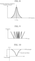
- FIG. 9 is an explanatory diagram illustrating an output waveform of the second frequency oscillator 22 capable of changing the frequency ⁇ f to be added.
- FIG. 9 illustrates a state in which the second frequency oscillator 22 changes the frequency ⁇ f to be added with the lapse of time.
- wavelength sweep of the second wavelength of the second laser beam can be performed as illustrated in FIG. 10 by changing the slope of the serrodyne modulation or the frequency modulation amount according to the change of the frequency ⁇ f to be added.
- FIG. 10 is an explanatory diagram illustrating a wavelength sweep of the second laser beam.
- the lidar device 1 illustrated in FIG. 1 can have a function of a wavelength sweep spectrometer as disclosed in Non-Patent Literature 3 below.
- an arrow indicates that the optical frequency f 0 + fz of the second laser beam is increased by performing the wavelength sweep.
- the frequency output unit 12 includes a first frequency oscillator 21, a second frequency oscillator 22, and a frequency mixer 23.
- the frequency output unit 12 may include a frequency conversion unit 24 instead of the second frequency oscillator 22.
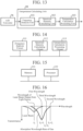
- FIG. 11 is a configuration diagram illustrating another lidar device 1 according to the first embodiment.
- the frequency conversion unit 24 is implemented by, for example, a frequency divider.
- the frequency conversion unit 24 converts the first frequency fi oscillated by the first frequency oscillator 21 into a frequency ⁇ f to be added, for example, by dividing the first frequency fi, and outputs the frequency ⁇ f to be added to each of the frequency mixer 23 and the frequency mixer 40.
- the lidar device 1 in which a frequency output unit 81 outputs a first frequency fi and a second frequency fz or a third frequency f 3 different from each of the first frequency fi and the second frequency fz to an optical transmission unit 82 will be described.
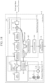
- FIG. 12 is a configuration diagram illustrating a lidar device 1 according to the second embodiment.
- the same reference numerals as those in FIG. 1 denote the same or corresponding parts, and thus description thereof is omitted.
- the lidar device 1 illustrated in FIG. 12 includes the frequency output unit 81, a reference light output unit 13, the optical transmission unit 82, an optical receiving unit 83, a density calculating unit 16, and a temperature calculating unit 84.
- the frequency output unit 81 includes a first frequency oscillator 21, a second frequency oscillator 22, a third frequency oscillator 25, and a frequency mixer 26.
- the frequency output unit 81 outputs the first frequency f 1 , the second frequency f 2 , or the third frequency f 3 to the optical transmission unit 82.
- the third frequency oscillator 25 oscillates a third frequency f 3 and outputs the third frequency f 3 to the frequency mixer 26.
- the frequency mixer 26 is implemented by, for example, a mixer.
- the frequency mixer 26 When the frequency ⁇ f to be added is not oscillated by the second frequency oscillator 22, the frequency mixer 26 outputs the first frequency fi oscillated by the first frequency oscillator 21 or the third frequency f 3 oscillated by the third frequency oscillator 25 to a frequency modulator 91 to be described later.
- the frequency mixer 26 When the frequency ⁇ f to be added is oscillated by the second frequency oscillator 22, the frequency mixer 26 outputs the second frequency fz, which is the frequency fi + ⁇ f of the sum of the first frequency fi oscillated by the first frequency oscillator 21 and the frequency ⁇ f to be added, to the frequency modulator 91.
- the optical transmission unit 82 includes an optical distributor 31, a frequency modulator 91, a pulse modulator 33, an optical amplifier 34, an optical circulator 35, and an optical antenna 36.
- the optical transmission unit 82 When the first frequency fi is output from the frequency output unit 81, the optical transmission unit 82 generates the first laser beam by modulating the optical frequency f 0 of the laser beam output from the light source 11 by the first frequency f 1 , and radiates the first laser beam into space.
- the optical transmission unit 82 When the second frequency fz is output from the frequency output unit 81, the optical transmission unit 82 generates the second laser beam by modulating the optical frequency f 0 of the laser beam output from the light source 11 by the second frequency fz, and radiates the second laser beam into space.
- the optical transmission unit 82 When the third frequency f 3 is output from the frequency output unit 81, the optical transmission unit 82 generates the third laser beam by modulating the optical frequency f 0 of the laser beam output from the light source 11 by the third frequency f 3 , and radiates the third laser beam into space.
- the third laser beam is a laser beam having a third wavelength included in the absorption wavelength band of the observation target gas, and is a laser beam having an absorption rate by the gas different from that of the first laser beam.
- the frequency modulator 91 is implemented by, for example, a modulation element using an acousto-optic element or a modulation element using a lithium niobate crystal.
- the frequency modulator 91 modulates the optical frequency f 0 of the laser beam output from the optical distributor 31 by the first frequency f 1 , and outputs the frequency-modulated laser beam to the pulse modulator 33 as the first laser beam.
- the optical frequency of the first laser beam is f 0 + fi.
- the frequency modulator 91 modulates the optical frequency f 0 of the laser beam output from the optical distributor 31 by the second frequency fz, and outputs the laser beam modulated by the second frequency fz to the pulse modulator 33 as the second laser beam.
- the optical frequency of the second laser beam is f 0 + f 2 .
- the frequency modulator 91 modulates the optical frequency f 0 of the laser beam output from the optical distributor 31 by the third frequency f 3 , and outputs the laser beam modulated by the third frequency f 3 to the pulse modulator 33 as the third laser beam.
- the optical frequency of the third laser beam is f 0 + f 3 .
- the optical receiving unit 83 includes an optical circulator 35, an optical antenna 36, an optical multiplexer 92, a balanced detector 93, a frequency discriminator 94, a frequency mixer 40, a signal multiplexer 95, and an A/D converter 96.
- the optical receiving unit 83 receives, as scattered light, the first laser beam radiated by the optical transmission unit 82 and then scattered by the scatterer floating in the space, the second laser beam radiated by the optical transmission unit and then scattered by the scatterer, or the third laser beam radiated by the optical transmission unit and then scattered by the scatterer, and detects interference light between the scattered light and the reference light.
- the optical multiplexer 92 is implemented by, for example, a beam splitter or a fiber type coupler.
- the optical multiplexer 92 detects interference light between scattered light output from the optical circulator 35 and reference light output from the optical distributor 31.
- the optical multiplexer 92 outputs the interference light to the balanced detector 93.
- the scattered light is subjected to the Doppler shift, and the optical frequencies f 0 + f 1 , f 0 + f 2 , and f 0 + f 3 of the scattered light are shifted. That is, when the lidar device 1 and the scatterer or the like are close to each other, the optical frequencies f 0 + f 1 , f 0 + f 2 , and f 0 + f 3 of the scattered light are increased by, for example, the frequency ⁇ f sft .
- the optical frequencies f 0 + f 1 , f 0 + fz, and f 0 + f 3 of the scattered light are lowered by, for example, the frequency ⁇ f sft .
- the optical multiplexer 92 outputs the interference light having the optical frequency fi + ⁇ f sft to the balanced detector 93 if the scattered light which is the scattered first laser beam is output from the optical circulator 35, and outputs the interference light having the optical frequency f 2 + ⁇ f sft to the balanced detector 93 if the scattered light which is the scattered second laser beam is output from the optical circulator 35.
- the optical multiplexer 92 outputs interference light having the optical frequency is + ⁇ f sft to the balanced detector 93.
- the optical multiplexer 92 When the lidar device 1 and the scatterer or the like are away from each other, the optical multiplexer 92 outputs the interference light having the optical frequency fi - ⁇ f sft to the balanced detector 93 if the scattered light which is the scattered first laser beam is output from the optical circulator 35, and outputs the interference light having the optical frequency f 2 - ⁇ f sft to the balanced detector 93 if the scattered light which is the scattered second laser beam is output from the optical circulator 35.
- the optical multiplexer 92 outputs interference light having the optical frequency f 3 - ⁇ f sft to the balanced detector 93.
- the optical multiplexer 92 outputs the interference light having the optical frequency fi to the balanced detector 93 if the scattered light that is the scattered first laser beam is output from the optical circulator 35, and outputs the interference light having the optical frequency f 2 to the balanced detector 93 if the scattered light that is the scattered second laser beam is output from the optical circulator 35. Furthermore, when the lidar device 1 does not move and the scatterer or the like does not move, if the scattered light that is the scattered third laser beam is output from the optical circulator 35, the optical multiplexer 92 outputs the interference light having the optical frequency is to the balanced detector 93.
- the balanced detector 93 is implemented by, for example, a balanced receiver that reduces in-phase noise by using two photodiodes.
- the balanced detector 93 converts the interference light output from the optical multiplexer 92 into an electric signal.
- the balanced detector 93 outputs the electric signal to the frequency discriminator 94.
- the frequency discriminator 94 When the electric signal related to the interference light having the optical frequency fz + ⁇ f sft , the electric signal related to the interference light having the optical frequency f 2 - ⁇ f sft , or the electric signal related to the interference light having the optical frequency fz is output from the balanced detector 93, the frequency discriminator 94 outputs these electric signals to the frequency mixer 40.
- the frequency discriminator 94 When the electric signal related to the interference light having the optical frequency fi + ⁇ f sft , the electric signal related to the interference light having the optical frequency fi - ⁇ f sft , or the electric signal related to the interference light having the optical frequency fi is output from the balanced detector 93, the frequency discriminator 94 outputs these electric signals to the signal multiplexer 95.
- the frequency discriminator 94 outputs these electric signals to the signal multiplexer 95.
- the signal multiplexer 95 Upon receiving the electric signal from the frequency discriminator 94, the signal multiplexer 95 outputs the electric signal to the A/D converter 96.
- the signal multiplexer 95 Upon receiving the electric signal from the frequency mixer 40, the signal multiplexer 95 outputs the electric signal to the A/D converter 96.
- the A/D converter 96 converts the analog electric signal output from the signal multiplexer 95 into a digital signal.
- the A/D converter 96 outputs the digital signal to each of the density calculating unit 16 and the temperature calculating unit 84.
- the temperature calculating unit 84 analyzes the optical frequency of the interference light detected by the optical receiving unit 83, and calculates the temperature of the gas from the analysis result of the optical frequency.
- the lidar device 1 illustrated in FIG. 12 includes the temperature calculating unit 84. However, this is merely an example, and the lidar device 1 may not include the temperature calculating unit 84, and a computer or the like different from the lidar device 1 may implement the temperature calculating unit 84. In this case, the A/D converter 96 outputs the digital signal to a computer or the like different from the lidar device 1.
- FIG. 13 is a configuration diagram illustrating the temperature calculating unit 84 of the lidar device 1 according to the second embodiment.
- FIG. 14 is a hardware configuration diagram illustrating hardware of the temperature calculating unit 84 of the lidar device 1 according to the second embodiment.
- the temperature calculating unit 84 illustrated in FIG. 13 includes a frequency analysis unit 101, a spectrum intensity calculating unit 102, and a temperature calculation processing unit 103.
- the frequency analysis unit 101 is implemented by, for example, a frequency analysis circuit 111 illustrated in FIG. 14 .
- the frequency analysis unit 101 converts the digital signal output from the A/D converter 96 into a signal in a frequency domain by performing fast Fourier transform on the digital signal for each predetermined time gate.
- the frequency analysis unit 101 outputs the signal in the frequency domain for a plurality of distance ranges to the spectrum intensity calculating unit 102.
- the spectrum intensity calculating unit 102 is implemented by, for example, a spectrum intensity calculating circuit 112 illustrated in FIG. 14 .
- the spectrum intensity calculating unit 102 calculates the intensity of the reception spectrum for each distance range from the signal in the frequency domain for each distance range output from the frequency analysis unit 101.
- the spectrum intensity calculating unit 102 calculates the intensity of the reception spectrum for each distance range from the signal in the frequency domain for each distance range output from the frequency analysis unit 101.
- the spectrum intensity calculating unit 102 calculates the intensity of the reception spectrum at the frequency fi + ⁇ f sft for each distance range.
- the spectrum intensity calculating unit 102 calculates the intensity of the reception spectrum at the frequency f 3 + ⁇ f sft for each distance range.
- the spectrum intensity calculating unit 102 calculates the intensity of the reception spectrum at the frequency fi - ⁇ f sft for each distance range.
- the spectrum intensity calculating unit 102 calculates the intensity of the reception spectrum at the frequency f 3 - ⁇ f sft for each distance range.
- the spectrum intensity calculating unit 102 calculates the intensity of the reception spectrum at the frequency fi for each distance range.
- the spectrum intensity calculating unit 102 calculates the intensity of the reception spectrum at the frequency is for each distance range.
- the spectrum intensity calculating unit 102 outputs the intensity of the reception spectrum for each distance range to the temperature calculation processing unit 103.
- the temperature calculation processing unit 103 is implemented by, for example, a temperature calculation processing circuit 113 illustrated in FIG. 14 .
- the temperature calculation processing unit 103 calculates the temperature of the gas from the intensity of the reception spectrum for each distance range output from the spectrum intensity calculating unit 102.
- each of the frequency analysis unit 101, the spectrum intensity calculating unit 102, and the temperature calculation processing unit 103, which are components of the temperature calculating unit 84, is implemented by dedicated hardware as illustrated in FIG. 14 . That is, it is assumed that the temperature calculating unit 84 is implemented by the frequency analysis circuit 111, the spectrum intensity calculating circuit 112, and the temperature calculation processing circuit 113.
- Each of the frequency analysis circuit 111, the spectrum intensity calculating circuit 112, and the temperature calculation processing circuit 113 corresponds to, for example, a single circuit, a composite circuit, a programmed processor, a parallel-programmed processor, ASIC, FPGA, or a combination thereof.
- the components of the temperature calculating unit 84 are not limited to those implemented by dedicated hardware, and the temperature calculating unit 84 may be implemented by software, firmware, or a combination of software and firmware.
- the software or firmware is stored in a memory of a computer as a program.
- the computer means hardware that executes a program, and corresponds to, for example, a CPU, a central processing unit, a processing unit, an arithmetic unit, a microprocessor, a microcomputer, a processor, or a DSP.
- FIG. 15 is a hardware configuration diagram of a computer in a case where the temperature calculating unit 84 is implemented by software, firmware, or the like.
- the temperature calculating unit 84 is implemented by software, firmware, or the like, a program for causing a computer to execute each processing procedure in the frequency analysis unit 101, the spectrum intensity calculating unit 102, and the temperature calculation processing unit 103 is stored in the memory 121. Then, a processor 122 of the computer executes the program stored in the memory 121.
- FIG. 14 illustrates an example in which each of the components of the temperature calculating unit 84 is implemented by dedicated hardware
- FIG. 15 illustrates an example in which the temperature calculating unit 84 is implemented by software, firmware, or the like.
- this is merely an example, and some components in the temperature calculating unit 84 may be implemented by dedicated hardware, and the remaining components may be implemented by software, firmware, or the like.
- the light source 11 outputs the laser beam to the optical distributor 31.
- the frequency output unit 81 outputs the first frequency f 1 , the second frequency f 2 , or the third frequency f 3 to the optical transmission unit 82.
- the frequency output unit 81 sequentially outputs the first frequency f 1 , the second frequency f 2 , and the third frequency f 3 to the optical transmission unit 82.
- the first frequency oscillator 21 oscillates a first frequency fi and outputs the first frequency fi to the frequency mixer 26.
- the second frequency oscillator 22 intermittently oscillates a frequency ⁇ f to be added, and intermittently outputs the frequency ⁇ f to be added to each of the frequency mixer 26 and the frequency mixer 40.
- the third frequency oscillator 25 oscillates a third frequency f 3 and outputs the third frequency f 3 to the frequency mixer 26.
- the frequency mixer 26 When the frequency ⁇ f to be added is not oscillated by the second frequency oscillator 22, the frequency mixer 26 outputs the first frequency fi oscillated by the first frequency oscillator 21 or the third frequency f 3 oscillated by the third frequency oscillator 25 to the frequency modulator 91.
- the frequency mixer 26 When the frequency ⁇ f to be added is oscillated by the second frequency oscillator 22, the frequency mixer 26 outputs the frequency fi + ⁇ f of the sum of the first frequency fi and the frequency ⁇ f to be added to the frequency modulator 91 as the second frequency f 2 .
- the optical distributor 31 Upon receiving the laser beam from the light source 11, the optical distributor 31 distributes the laser beam at a predetermined ratio, as in the first embodiment.
- the optical distributor 31 outputs one of the distributed laser beams to the frequency modulator 91 and outputs the other of the distributed laser beams to the optical multiplexer 92.
- the frequency modulator 91 acquires the laser beam from the optical distributor 31.
- the frequency modulator 91 When acquiring the first frequency fi from the frequency mixer 26, the frequency modulator 91 modulates the optical frequency f 0 of the laser beam output from the optical distributor 31 by the first frequency fi.
- the frequency modulator 91 outputs the laser beam modulated by the first frequency fi to the pulse modulator 33 as a first laser beam.
- the optical frequency of the first laser beam is f 0 + fi.
- the frequency modulator 91 When acquiring the second frequency f 2 from the frequency mixer 26, the frequency modulator 91 modulates the optical frequency f 0 of the laser beam by the second frequency f 2 .
- the frequency modulator 91 outputs the laser beam modulated by the second frequency f 2 to the pulse modulator 33 as a second laser beam.
- the optical frequency of the second laser beam is f 0 + f 2 .
- the frequency modulator 91 When acquiring the third frequency is from the frequency mixer 26, the frequency modulator 91 modulates the optical frequency f 0 of the laser beam by the third frequency f 3 .
- the frequency modulator 91 outputs the laser beam modulated by the third frequency f 3 to the pulse modulator 33 as a third laser beam.
- the optical frequency of the third laser beam is f 0 + f 3 .
- FIG. 16 is an explanatory diagram illustrating an absorption wavelength band of gas, a wavelength of a laser beam output from the light source 11, a first wavelength, a second wavelength, and a third wavelength.
- the horizontal axis represents the wavelength
- the vertical axis represents the transmittance of the laser beam to the gas.
- a broken line indicates a laser beam output from the light source 11, and a solid line indicates an absorption wavelength band of gas.
- the first wavelength is included in the absorption wavelength band of the gas, and the second wavelength is not included in the absorption wavelength band of the gas.
- the third wavelength is included in the absorption wavelength band of the gas and is different from the first wavelength.
- the transmittance of the second wavelength by the gas is larger than each of the transmittance of the first wavelength by the gas and the transmittance of the third wavelength by the gas. That is, the absorption rate of the second wavelength by the gas is smaller than each of the absorption rate of the first wavelength by the gas and the absorption rate of the third wavelength by the gas.
- the first laser beam, the second laser beam, or the third laser beam is radiated from the optical antenna 36 to the space.
- the optical multiplexer 92 acquires scattered light from the optical circulator 35 and acquires reference light from the optical distributor 31.
- the optical multiplexer 92 detects interference light between the scattered light and the reference light.
- the scattered light is subjected to the Doppler shift, and the optical frequencies f 0 + f 1 , f 0 + fz, and f 0 + f 3 of the scattered light are shifted. That is, when the lidar device 1 and the scatterer or the like are close to each other, the optical frequencies f 0 + f 1 , f 0 + fz, and f 0 + f 3 of the scattered light are increased by, for example, the frequency ⁇ f sft .
- the optical frequencies f 0 + f 1 , f 0 + fz, and f 0 + is of the scattered light are lowered by, for example, the frequency ⁇ f sft .
- the optical multiplexer 92 outputs interference light having an optical frequency fi + ⁇ f sft to the balanced detector 93.
- the optical multiplexer 92 When the lidar device 1 and the scatterer or the like are close to each other, if the scattered light that is the scattered second laser beam is output from the optical circulator 35, the optical multiplexer 92 outputs the interference light having the optical frequency fz + ⁇ f sft to the balanced detector 93.
- the optical multiplexer 92 outputs interference light having the optical frequency is + ⁇ f sft to the balanced detector 93.
- the optical multiplexer 92 When the lidar device 1 and the scatterer or the like are away from each other, if the scattered light that is the scattered first laser beam is output from the optical circulator 35, the optical multiplexer 92 outputs the interference light having the optical frequency fi - ⁇ f sft to the balanced detector 93.
- the optical multiplexer 92 When the lidar device 1 and the scatterer or the like are away from each other, if scattered light that is the scattered second laser beam is output from the optical circulator 35, the optical multiplexer 92 outputs interference light having the optical frequency f 2 - ⁇ f sft to the balanced detector 93.
- the optical multiplexer 92 outputs interference light having the optical frequency f 3 - ⁇ f sft to the balanced detector 93.
- the balanced detector 93 acquires interference light from the optical multiplexer 92 and converts the interference light into an electric signal.
- the balanced detector 93 outputs the electric signal to the frequency discriminator 94.
- the frequency discriminator 94 When the frequency discriminator 94 acquires an electric signal related to the interference light having the optical frequency f 2 + ⁇ f sft , an electric signal related to the interference light having the optical frequency f 2 - ⁇ f sft , or an electric signal related to the interference light having the optical frequency fz from the balanced detector 93, the frequency discriminator outputs the acquired electric signal to the frequency mixer 40.
- the frequency discriminator 94 When the frequency discriminator 94 acquires the electric signal related to the interference light having the optical frequency fi + ⁇ f sft , the electric signal related to the interference light having the optical frequency fi - ⁇ f sft , or the electric signal related to the interference light having the optical frequency fi from the balanced detector 93, the frequency discriminator outputs the acquired electric signal to the signal multiplexer 95.
- the frequency discriminator 94 acquires an electric signal related to the interference light having the optical frequency f 3 + ⁇ f sft , an electric signal related to the interference light having the optical frequency f 3 - ⁇ f sft , or an electric signal related to the interference light having the optical frequency f 3 from the balanced detector 93, the frequency discriminator outputs the acquired electric signal to the signal multiplexer 95.
- the frequency mixer 40 When the frequency of the electric signal output from the frequency discriminator 94 is fz + ⁇ f sft , the frequency mixer 40 down-converts the frequency of the electric signal to fi + ⁇ f sft using the frequency ⁇ f to be added.
- the frequency mixer 40 When the frequency of the electric signal output from the frequency discriminator 94 is fz - ⁇ f sft , the frequency mixer 40 down-converts the frequency of the electric signal to fi - ⁇ f sft using the frequency ⁇ f to be added.
- the frequency mixer 40 When the frequency of the electric signal output from the frequency discriminator 94 is fz, the frequency mixer 40 down-converts the frequency of the electric signal to fi using the frequency ⁇ f to be added.
- the frequency mixer 40 outputs the down-converted electric signal to the signal multiplexer 95.
- the signal multiplexer 95 Upon receiving the electric signal from the frequency discriminator 94, the signal multiplexer 95 outputs the electric signal to the A/D converter 96.
- the signal multiplexer 95 when acquiring an electric signal having the frequency fi + ⁇ f sft , an electric signal having the frequency fi - ⁇ f sft , or an electric signal having the frequency fi from the frequency discriminator 94, the signal multiplexer 95 outputs the electric signal having the frequency fi + ⁇ f sft , the electric signal having the frequency fi - ⁇ f sft , or the electric signal having the frequency fi to the A/D converter 96.
- the signal multiplexer 95 acquires an electric signal having the frequency f 3 + ⁇ f sft , an electric signal having the frequency f 3 - ⁇ f sft , or an electric signal having the frequency f 3 from the frequency discriminator 94, the signal multiplexer 95 outputs the electric signal having the frequency f 3 + ⁇ f sft , the electric signal having the frequency f 3 - ⁇ f sft , or the electric signal having the frequency f 3 to the A/D converter 96.
- the signal multiplexer 95 Upon receiving the electric signal from the frequency mixer 40, the signal multiplexer 95 outputs the electric signal to the A/D converter 96.
- the signal multiplexer 95 when acquiring an electric signal having the frequency fi + ⁇ f sft , an electric signal having the frequency fi - ⁇ f sft , or an electric signal having the frequency fi from the frequency mixer 40, the signal multiplexer 95 outputs the electric signal having the frequency fi + ⁇ f sft , the electric signal having the frequency fi - ⁇ f sft , or the electric signal having the frequency fi to the A/D converter 96.
- the A/D converter 96 acquires the electric signal from the signal multiplexer 95.
- the A/D converter 96 converts an analog electric signal into a digital signal, and outputs the digital signal to each of the density calculating unit 16 and the temperature calculating unit 84.
- the density calculating unit 16 acquires the digital signal from the A/D converter 96.
- the density calculating unit 16 converts the digital signal into a signal in the frequency domain by performing fast Fourier transform on the digital signal for each predetermined time gate, and analyzes the frequency of the interference light.
- the density calculating unit 16 calculates the density of the gas from the analysis result of the frequency.
- the density calculating unit 16 calculates the density of the gas from the intensity of the reception spectrum at the frequency f 1 + ⁇ f sft when the first laser beam is radiated and the intensity of the reception spectrum at the frequency f 1 + ⁇ f sft when the second laser beam is radiated, as in the first embodiment.
- the density calculating unit 16 calculates the density of the gas from the intensity of the reception spectrum at the frequency f 1 - ⁇ f sft when the first laser beam is radiated and the intensity of the reception spectrum at the frequency f 1 - ⁇ f sft when the second laser beam is radiated, as in the first embodiment.
- the density calculating unit 16 calculates the density of the gas from the intensity of the reception spectrum at the frequency f 1 when the first laser beam is radiated and the intensity of the reception spectrum at the frequency f 1 when the second laser beam is radiated, as in the first embodiment.
- the density calculating unit 16 may calculate the density of the gas from the intensity of the reception spectrum at the frequency f 3 + ⁇ f sft which is the reception intensity of the ON wavelength and the intensity of the reception spectrum at the frequency f 1 + ⁇ f sft which is the reception intensity of the OFF wavelength.
- the density calculating unit 16 may calculate the density of the gas from the intensity of the reception spectrum at the frequency f 3 - ⁇ f sft which is the reception intensity of the ON wavelength and the intensity of the reception spectrum at the frequency f 1 - ⁇ f sft which is the reception intensity of the OFF wavelength.
- the density calculating unit 16 may calculate the density of the gas from the intensity of the reception spectrum at the frequency f 3 which is the reception intensity of the ON wavelength and the intensity of the reception spectrum at the frequency f 1 which is the reception intensity of the OFF wavelength.
- the frequency analysis unit 101 of the temperature calculating unit 84 acquires a digital signal from the A/D converter 96.
- the frequency analysis unit 101 converts the digital signal into a signal in the frequency domain by performing fast Fourier transform on the digital signal for each predetermined time gate.
- the frequency analysis unit 101 outputs the signal in the frequency domain for a distance range corresponding to each time gate to the spectrum intensity calculating unit 102.
- the spectrum intensity calculating unit 102 acquires the signal in the frequency domain for each distance range from the frequency analysis unit 101.
- the spectrum intensity calculating unit 102 detects the reception spectrum of the frequency f 1 + ⁇ f sft from the signal in the frequency domain for each distance range.
- the reception spectrum of the frequency f 1 + ⁇ f sft detected by the spectrum intensity calculating unit 102 is a spectrum obtained by converting the digital signal related to the electric signal of the frequency f 1 + ⁇ f sft output from the frequency discriminator 94 into a signal in the frequency domain.
- the spectrum intensity calculating unit 102 detects the reception spectrum of the frequency f 1 + ⁇ f sft from the signal in the frequency domain for each distance range.
- the reception spectrum at the frequency f 1 + ⁇ f sft detected by the spectrum intensity calculating unit 102 is a spectrum obtained by converting the digital signal related to the electric signal having the frequency f 1 + ⁇ f sft output from the frequency mixer 40 into a signal in the frequency domain.
- the optical multiplexer 92 detects the interference light having the optical frequency f 3 + ⁇ f sft
- the spectrum intensity calculating unit 102 detects the reception spectrum of the frequency f 3 + ⁇ f sft from the signal in the frequency domain for each distance range.
- the spectrum intensity calculating unit 102 detects the reception spectrum at the frequency f 1 - ⁇ f sft for each distance range.
- the reception spectrum at the frequency f 1 - ⁇ f sft detected by the spectrum intensity calculating unit 102 is a spectrum obtained by converting the digital signal related to the electric signal having the frequency f 1 - ⁇ f sft output from the frequency discriminator 94 into a signal in the frequency domain.
- the spectrum intensity calculating unit 102 detects the reception spectrum at the frequency f 1 - ⁇ f sft for each distance range.
- the reception spectrum at the frequency f 1 - ⁇ f sft detected by the spectrum intensity calculating unit 102 is a spectrum obtained by converting the digital signal related to the electric signal having the frequency f 1 - ⁇ f sft output from the frequency mixer 40 into a signal in the frequency domain.
- the spectrum intensity calculating unit 102 detects the reception spectrum at the frequency f 3 - ⁇ f sft from the signal in the frequency domain for each distance range.
- the spectrum intensity calculating unit 102 detects the reception spectrum at the frequency f 1 for each distance range.
- the reception spectrum at the frequency f 1 detected by the spectrum intensity calculating unit 102 is a spectrum obtained by converting the digital signal related to the electric signal having the frequency f 1 output from the frequency discriminator 94 into a signal in the frequency domain.
- the spectrum intensity calculating unit 102 detects the reception spectrum at the frequency f 1 for each distance range.
- the reception spectrum at the frequency f 1 detected by the spectrum intensity calculating unit 102 is a spectrum obtained by converting the digital signal related to the electric signal having the frequency f 1 output from the frequency mixer 40 into a signal in the frequency domain.
- the optical multiplexer 92 detects the interference light having the optical frequency f 3
- the spectrum intensity calculating unit 102 detects the reception spectrum at the frequency f 3 for each distance range.
- the spectrum intensity calculating unit 102 calculates, for each distance range, the intensity of the reception spectrum at the frequency f 1 + ⁇ f sft when the first laser beam is radiated, the intensity of the reception spectrum at the frequency f 1 + ⁇ f sft when the second laser beam is radiated, and the intensity of the reception spectrum at the frequency is + ⁇ f sft when the third laser beam is radiated.
- the spectrum intensity calculating unit 102 calculates, for each distance range, the intensity of the reception spectrum at the frequency f 1 - ⁇ f sft when the first laser beam is radiated, the intensity of the reception spectrum at the frequency f 1 - ⁇ f sft when the second laser beam is radiated, and the intensity of the reception spectrum at the frequency f 3 - ⁇ f sft when the third laser beam is radiated.
- the spectrum intensity calculating unit 102 calculates, for each distance range, the intensity of the reception spectrum at the frequency f 1 when the first laser beam is radiated, the intensity of the reception spectrum at the frequency f 1 when the second laser beam is radiated, and the intensity of the reception spectrum at the frequency f 3 when the third laser beam is radiated.
- the processing of calculating the intensity of the reception spectrum by the spectrum intensity calculating unit 102 is similar to the processing of calculating the intensity of the reception spectrum by the spectrum intensity calculating unit 52.
- the spectrum intensity calculating unit 102 outputs the intensity of the reception spectrum for each distance range to the temperature calculation processing unit 103.
- the temperature calculation processing unit 103 acquires, from the spectrum intensity calculating unit 102, the intensity of the reception spectrum at the frequency f 1 + ⁇ f sft when the first laser beam is radiated, the intensity of the reception spectrum at the frequency f 1 + ⁇ f sft when the second laser beam is radiated, and the intensity of the reception spectrum at the frequency f 3 + ⁇ f sft when the third laser beam is radiated, for each distance range.
- the temperature calculation processing unit 103 calculates the temperature of the gas from the two intensities of the reception spectra at the frequency f 1 + ⁇ f sft and the intensity of the reception spectrum at the frequency is + ⁇ f sft for each distance range.
- the intensity of the reception spectrum at the frequency f 1 + ⁇ f sft which is the reception intensity of the ON wavelength, the intensity of the reception spectrum at the frequency f 1 + ⁇ f sft which is the reception intensity of the OFF wavelength, and the intensity of the reception spectrum at the frequency f 3 + ⁇ f sft which is the reception intensity of the ON wavelength are used for calculation of the temperature of the gas by the temperature calculation processing unit 103.
- the temperature calculation processing unit 103 acquires, from the spectrum intensity calculating unit 102, the intensity of the reception spectrum at the frequency f 1 - ⁇ f sft when the first laser beam is radiated, the intensity of the reception spectrum at the frequency f 1 - ⁇ f sft when the second laser beam is radiated, and the intensity of the reception spectrum at the frequency f 3 - ⁇ f sft when the third laser beam is radiated, for each distance range.
- the temperature calculation processing unit 103 calculates the temperature of the gas from the two intensities of the reception spectra at the frequency f 1 - ⁇ f sft and the intensity of the reception spectrum at the frequency f 3 - ⁇ f sft for each distance range.
- the intensity of the reception spectrum at the frequency f 1 - ⁇ f sft which is the reception intensity of the ON wavelength, the intensity of the reception spectrum at the frequency f 1 - ⁇ f sft which is the reception intensity of the OFF wavelength, and the intensity of the reception spectrum at the frequency f 3 - ⁇ f sft which is the reception intensity of the ON wavelength are used for calculation of the temperature of the gas by the temperature calculation processing unit 103.
- the temperature calculation processing unit 103 acquires, from the spectrum intensity calculating unit 102, the intensity of the reception spectrum at the frequency f 1 when the first laser beam is radiated, the intensity of the reception spectrum at the frequency f 1 when the second laser beam is radiated, and the intensity of the reception spectrum at the frequency f 3 when the third laser beam is radiated, for each distance range.
- the temperature calculation processing unit 103 calculates the temperature of the gas from the two intensities of the reception spectra at the frequency f 1 and the intensity of the reception spectrum at the frequency f 3 for each distance range.
- the intensity of the reception spectrum at the frequency f 1 which is the reception intensity of the ON wavelength, the intensity of the reception spectrum at the frequency f 1 which is the reception intensity of the OFF wavelength, and the intensity of the reception spectrum at the frequency f 3 which is the reception intensity of the ON wavelength are used for calculation of the temperature of the gas by the temperature calculation processing unit 103.
- the processing itself of calculating the temperature of the gas from the three intensities of the reception spectra at the three frequencies is a known technique, and is disclosed in, for example, Non-Patent Literature 4 below. Therefore, details of the processing of calculating the temperature of the gas will be omitted.
- the lidar device 1 is configured so that the frequency output unit 81 outputs the first frequency, the second frequency, or the third frequency to the optical transmission unit 82, the optical transmission unit 82 modulates the optical frequency of the laser beam output from the light source 11 by the third frequency when the third frequency is output from the frequency output unit 81, and radiates the laser beam modulated by the third frequency into space as the third laser beam having the wavelength included in the absorption wavelength band, and the optical receiving unit 83 receives the first laser beam scattered by the scatterer, the second laser beam scattered by the scatterer, or the third laser beam scattered by the scatterer as the scattered light, and detects the interference light between the scattered light and the reference light.
- the lidar device 1 includes a temperature calculating unit 84 that analyzes the optical frequency of the interference light detected by the optical receiving unit 83 and calculates the temperature of the gas from the analysis result of the optical frequency. Therefore, even in a situation where the relative position between the gas and the lidar device 1 changes or a situation where the distribution of the scatterers floating in the space changes, the lidar device 1 can calculate the temperature of the gas in addition to preventing the degradation of the calculation accuracy in the density of the gas.
- the first wavelength and the third wavelength are wavelengths included in the absorption wavelength band of the same gas.
- the first wavelength and the third wavelength may be wavelengths included in absorption wavelength bands of different gases. That is, the first wavelength may be a wavelength included in the absorption wavelength band of the first gas, and the third wavelength may be a wavelength included in the absorption wavelength band of the second gas.
- the second wavelength is a wavelength that is not included in the absorption wavelength band of the first gas and is not included in the absorption wavelength band of the second gas.
- the density calculating unit 16 calculates the density of the first gas from the intensity of the reception spectrum at the frequency f 1 + ⁇ f sft which is the reception intensity of the ON wavelength and the intensity of the reception spectrum at the frequency f 1 + ⁇ f sft which is the reception intensity of the OFF wavelength, and calculates the density of the second gas from the intensity of the reception spectrum at the frequency f 3 + ⁇ f sft which is the reception intensity of the ON wavelength and the intensity of the reception spectrum at the frequency f 1 + ⁇ f sft which is the reception intensity of the OFF wavelength.
- the density calculating unit 16 calculates the density of the first gas from the intensity of the reception spectrum at the frequency f 1 - ⁇ f sft which is the reception intensity of the ON wavelength and the intensity of the reception spectrum at the frequency f 1 - ⁇ f sft which is the reception intensity of the OFF wavelength, and calculates the density of the second gas from the intensity of the reception spectrum at the frequency f 3 - ⁇ f sft which is the reception intensity of the ON wavelength and the intensity of the reception spectrum at the frequency f 1 - ⁇ f sft which is the reception intensity of the OFF wavelength.
- the density calculating unit 16 calculates the density of the first gas from the intensity of the reception spectrum at the frequency f 1 which is the reception intensity of the ON wavelength and the intensity of the reception spectrum at the frequency f 1 which is the reception intensity of the OFF wavelength, and calculates the density of the second gas from the intensity of the reception spectrum at the frequency f 3 which is the reception intensity of the ON wavelength and the intensity of the reception spectrum at the frequency f 1 which is the reception intensity of the OFF wavelength.
- the lidar device 1 illustrated in FIG. 12 can calculate the densities of two different gases.
- a lidar device 1 in which a reference light output unit 131 includes a frequency modulator 141 in addition to the optical distributor 31 will be described.
- FIG. 17 is a configuration diagram illustrating the lidar device 1 according to the third embodiment.
- the same reference numerals as those in FIG. 1 denote the same or corresponding parts, and thus description thereof is omitted.
- the lidar device 1 illustrated in FIG. 17 includes a light source 11, a frequency output unit 12, the reference light output unit 131, an optical transmission unit 14, an optical receiving unit 132, and a density calculating unit 16.
- the frequency output unit 12 outputs the first frequency f 1 or the second frequency fz to the optical transmission unit 14 as in the first embodiment.
- the frequency output unit 12 when outputting the first frequency f 1 to the optical transmission unit 14, does not output the frequency ⁇ f to be added to the reference light output unit 131.
- the reference light output unit 131 includes an optical distributor 31 and a frequency modulator 141.
- the reference light output unit 131 When the first frequency f 1 is output from the frequency output unit 12 to the optical transmission unit 14, the reference light output unit 131 outputs the laser beam output from the light source 11 to the optical receiving unit 132 as reference light.
- the reference light output unit 131 modulates the laser beam output from the light source 11 by the frequency ⁇ f to be added.
- the reference light output unit 131 outputs the laser beam modulated by the frequency ⁇ f to be added to the optical receiving unit 132 as reference light.
- the frequency modulator 141 is implemented by, for example, a modulation element using an acousto-optic element or a modulation element using a lithium niobate crystal.
- the frequency modulator 141 When the frequency ⁇ f to be added is not output from the second frequency oscillator 22, the frequency modulator 141 outputs the laser beam output from the optical distributor 31 to the optical multiplexer 142 as reference light.
- the optical frequency of the reference light is f 0 .
- the frequency modulator 141 modulates the laser beam output from the optical distributor 31 by the frequency ⁇ f to be added.
- the frequency modulator 141 outputs the laser beam modulated by the frequency ⁇ f to be added to the optical multiplexer 142 as reference light.
- the optical receiving unit 132 includes an optical circulator 35, an optical antenna 36, an optical multiplexer 142, a balanced detector 143, and an A/D converter 144.
- the optical receiving unit 132 receives, as scattered light, the first laser beam radiated from the optical transmission unit 14 and then scattered by the scatterer floating in the space or the second laser beam radiated from the optical transmission unit and then scattered by the scatterer, and detects interference light between the scattered light and the reference light.
- the optical multiplexer 142 is implemented by, for example, a beam splitter or a fiber type coupler.
- the optical multiplexer 142 detects interference light between scattered light output from the optical circulator 35 and reference light output from the frequency modulator 141.
- the optical multiplexer 142 outputs the interference light to the balanced detector 143.
- the optical multiplexer 142 When the lidar device 1 and the scatterer or the like are close to each other, if scattered light that is the scattered first laser beam is output from the optical circulator 35, the optical multiplexer 142 outputs interference light having an optical frequency f 1 + ⁇ f sft to the balanced detector 143 since the optical frequency of the reference light is f 0 .
- the optical multiplexer 142 outputs interference light having the optical frequency f 1 + ⁇ f sft to the balanced detector 143 since the optical frequency of the reference light is f 0 + fz - f 1 .
- the optical multiplexer 142 When the lidar device 1 and the scatterer or the like are away from each other, if scattered light that is the scattered first laser beam is output from the optical circulator 35, the optical multiplexer 142 outputs interference light having the optical frequency f 1 - ⁇ f sft to the balanced detector 143 since the optical frequency of the reference light is f 0 .
- the optical multiplexer 142 outputs interference light having the optical frequency f 1 - ⁇ f sft to the balanced detector 143 since the optical frequency of the reference light is f 0 + fz - f 1 .
- the optical multiplexer 142 outputs the interference light having the optical frequency f 1 to the balanced detector 143 since the optical frequency of the reference light is f 0 .
- the optical multiplexer 142 outputs interference light of the optical frequency f 1 to the balanced detector 143 since the optical frequency of the reference light is f 0 + fz - f 1 .
- the balanced detector 143 is implemented by, for example, a balanced receiver that reduces in-phase noise by using two photodiodes.
- the balanced detector 143 converts the interference light output from the optical multiplexer 142 into an electric signal.
- the balanced detector 143 outputs the electric signal to the A/D converter 144.
- the A/D converter 144 converts the analog electric signal output from the balanced detector 143 into a digital signal.
- the A/D converter 144 outputs the digital signal to the density calculating unit 16.
- the light source 11 outputs the laser beam to the optical distributor 31.
- the frequency output unit 12 outputs the first frequency f 1 or the second frequency f 2 to the optical transmission unit 14. For example, the frequency output unit 12 alternately outputs the first frequency f 1 and the second frequency fz to the optical transmission unit 14.
- the first frequency oscillator 21 oscillates a first frequency f 1 and outputs the first frequency f 1 to the frequency mixer 23.
- the second frequency oscillator 22 intermittently oscillates the frequency ⁇ f to be added, and intermittently outputs the frequency ⁇ f to be added to the frequency mixer 23.
- the second frequency oscillator 22 when outputting the frequency ⁇ f to be added to the frequency mixer 23, outputs the frequency ⁇ f to be added to the frequency modulator 141.
- the frequency mixer 23 When the frequency ⁇ f to be added is not output from the second frequency oscillator 22, the frequency mixer 23 outputs the first frequency f 1 oscillated by the first frequency oscillator 21 to the frequency modulator 32.
- the frequency mixer 23 When the frequency ⁇ f to be added is output from the second frequency oscillator 22, the frequency mixer 23 outputs the frequency f 1 + ⁇ f of the sum of the first frequency f 1 and the frequency ⁇ f to be added to the frequency modulator 32 as the second frequency f 2 .
- the optical distributor 31 Upon receiving the laser beam from the light source 11, the optical distributor 31 distributes the laser beam at a predetermined ratio.
- the predetermined ratio is, for example, a ratio of 90 on the frequency modulator 32 side and a ratio of 10 on the frequency modulator 141 side.
- the optical distributor 31 outputs one of the distributed laser beams to the frequency modulator 32 and outputs the other of the distributed laser beams to the frequency modulator 141.
- the first laser beam or the second laser beam is radiated from the optical antenna 36 to a space where gas is present.
- the first laser beam scattered by the scatterer floating in the space or the second laser beam scattered by the scatterer is received by the optical antenna 36 as scattered light.
- the optical circulator 35 outputs the scattered light received by the optical antenna 36 to the optical multiplexer 142.
- the frequency modulator 141 When the frequency ⁇ f to be added is not output from the second frequency oscillator 22, the frequency modulator 141 outputs the laser beam output from the light source 11 to the optical multiplexer 142 as reference light.
- the optical frequency of the reference light is f 0 .
- the frequency modulator 141 modulates the optical frequency f 0 of the laser beam output from the light source 11 by the second frequency f 2 .
- the frequency modulator 141 outputs the laser beam modulated by the second frequency fz to the optical multiplexer 142 as reference light.
- the optical frequency of the reference light is f 0 + fz.
- the optical multiplexer 142 acquires scattered light from the optical circulator 35 and reference light from the frequency modulator 141.
- the optical multiplexer 142 detects interference light between scattered light and reference light.
- the lidar device 1 moves or the gas and the scatterer move
- the scattered light is subjected to the Doppler shift
- the optical frequencies f 0 + f 1 and f 0 + fz of the scattered light are shifted. That is, when the lidar device 1 and the scatterer or the like are close to each other, the optical frequencies f 0 + f 1 and f 0 + fz of the scattered light are increased by, for example, the frequency ⁇ f sft .
- the optical frequencies f 0 + f 1 and f 0 + fz of the scattered light are decreased by, for example, the frequency ⁇ f sft .
- the optical frequencies f 0 + f 1 and f 0 + fz of the scattered light do not change.
- ⁇ f sft 0.
- the optical multiplexer 142 outputs interference light having an optical frequency f 1 + ⁇ f sft to the balanced detector 143.
- the optical multiplexer 142 outputs interference light having an optical frequency f 1 + ⁇ f sft to the balanced detector 143, similarly to when the scattered first laser beam is output.
- the optical multiplexer 142 When the lidar device 1 and the scatterer or the like are away from each other, if the scattered light which is the scattered first laser beam is output from the optical circulator 35, the optical multiplexer 142 outputs the interference light having the optical frequency f 1 - ⁇ f sft to the balanced detector 143.
- the optical multiplexer 142 outputs interference light having an optical frequency f 1 - ⁇ f sft to the balanced detector 143, similarly to when the scattered first laser beam is output.
- the optical multiplexer 142 outputs the interference light having the optical frequency f 1 to the balanced detector 143.
- the optical multiplexer 142 outputs interference light having the optical frequency f 1 to the balanced detector 143 similarly to when the scattered first laser beam is output.
- the balanced detector 143 acquires interference light from the optical multiplexer 142 and converts the interference light into an electric signal.
- the balanced detector 143 outputs the electric signal to the A/D converter 144.
- the A/D converter 144 acquires the electric signal from the balanced detector 143.
- the A/D converter 144 converts the analog electric signal into a digital signal and outputs the digital signal to the density calculating unit 16.
- the density calculating unit 16 Upon receiving the digital signal from the A/D converter 144, the density calculating unit 16 calculates the density of the gas.
- the density calculating unit 16 calculates the density of the gas by substituting the intensity of the reception spectrum at the frequency f 1 + ⁇ f sft when the first laser beam is radiated and the intensity of the reception spectrum at the frequency f 1 + ⁇ f sft when the second laser beam is radiated into Formula (2).
- the density calculating unit 16 calculates the density of the gas by substituting the intensity of the reception spectrum at the frequency f 1 - ⁇ f sft when the first laser beam is radiated and the intensity of the reception spectrum at the frequency f 1 - ⁇ f sft when the second laser beam is radiated into Formula (2).
- the density calculating unit 16 calculates the density of the gas by substituting the intensity of the reception spectrum at the frequency f 1 when the first laser beam is radiated and the intensity of the reception spectrum at the frequency f 1 when the second laser beam is radiated into Formula (2).
- the density of the gas can be calculated without including two light sources.
- the frequency discriminator 39, the frequency mixer 40, and the signal multiplexer 41 are unnecessary.
- the frequency modulator 141 is used in the lidar device 1 illustrated in FIG. 1 .
- the frequency mixer 23 of the frequency output unit 12 outputs the first frequency f 1 or the second frequency fz to the frequency modulator 32 of the optical transmission unit 14.
- the second frequency oscillator 22 of the frequency output unit 12 outputs the frequency ⁇ f to be added to the frequency mixer 23, the second frequency oscillator 22 outputs the frequency ⁇ f to be added to the frequency modulator 141 of the reference light output unit 131.
- the second frequency oscillator 22' of the frequency output unit 12 may intermittently output the second frequency f 2 to the frequency modulator 32, and the frequency mixer 23' may output the first frequency f 1 or the frequency f 1 + f 2 which is the sum of the first frequency f 1 and the second frequency fz to the frequency modulator 141.
- FIG. 18 is a configuration diagram illustrating another lidar device 1 according to the third embodiment.
- the frequency output unit 12 includes a first frequency oscillator 21, a second frequency oscillator 22', and a frequency mixer 23'.
- the second frequency oscillator 22' intermittently oscillates the second frequency fz, and intermittently outputs the second frequency fz to each of the frequency modulator 32 and the frequency mixer 23'.
- the frequency mixer 23' outputs the first frequency f 1 oscillated by the first frequency oscillator 21 to the frequency modulator 141.
- the frequency mixer 23' outputs the frequency f 1 + fz, which is the sum of the first frequency f 1 and the second frequency fz, to the frequency modulator 141.
- the frequency modulator 32 of the optical transmission unit 14 when the second frequency fz is not output from the second frequency oscillator 22', the frequency modulator 32 of the optical transmission unit 14 does not modulate the optical frequency f 0 of the laser beam output from the optical distributor 31 by the first frequency f 1 , and outputs the laser beam to the pulse modulator 33 as the first laser beam.
- the frequency modulator 32 When the second frequency fz is output from the second frequency oscillator 22', the frequency modulator 32 generates the second laser beam by modulating the optical frequency f 0 of the laser beam output from the optical distributor 31 by the second frequency fz, and outputs the second laser beam to the pulse modulator 33.
- the wavelength of the laser beam output from the light source 11 is included in the absorption wavelength band of the gas.
- the second laser beam generated by modulating by the second frequency fz has a lower absorption rate by gas than that of the first laser beam.
- the frequency modulator 141 of the reference light output unit 131 modulates the optical frequency f 0 of the laser beam output from the optical distributor 31 by the first frequency f 1 , and outputs the laser beam modulated by the first frequency f 1 to the optical multiplexer 142 as reference light.
- the frequency modulator 141 modulates the optical frequency f 0 of the laser beam output from the optical distributor 31 by the sum frequency f 1 + fz, and outputs the laser beam modulated by the sum frequency f 1 + fz to the optical multiplexer 142 as reference light.
- the optical multiplexer 142 acquires the reference light having the optical frequency f 0 + f 1 from the frequency modulator 141 and acquires the scattered light having the optical frequency f 0 + ⁇ f sft from the optical circulator 35.
- the optical multiplexer 142 acquires the reference light having the optical frequency of f 0 + f 1 + fz from the frequency modulator 141 and acquires the scattered light having the optical frequency of f 0 + f 2 + ⁇ f sft from the optical circulator 35.
- the optical multiplexer 142 acquires the reference light having the optical frequency f 0 + f 1 from the frequency modulator 141 and acquires the scattered light having the optical frequency f 0 - ⁇ f sft from the optical circulator 35.
- the optical multiplexer 142 acquires the reference light having the optical frequency f 0 + f 1 + fz from the frequency modulator 141 and acquires the scattered light having the optical frequency f 0 + fz - ⁇ f sft from the optical circulator 35.
- the optical multiplexer 142 acquires the reference light having the optical frequency f 0 + f 1 from the frequency modulator 141 and acquires the scattered light having the optical frequency f 0 from the optical circulator 35.
- the optical multiplexer 142 acquires the reference light having the optical frequency f 0 + f 1 + fz from the frequency modulator 141 and acquires the scattered light having the optical frequency f 0 + fz from the optical circulator 35.
- the balanced detector 143 acquires interference light from the optical multiplexer 142 and converts the interference light into an electric signal.
- the balanced detector 143 outputs the electric signal to the A/D converter 144.
- the A/D converter 144 acquires the electric signal from the balanced detector 143.
- the A/D converter 144 converts the analog electric signal into a digital signal and outputs the digital signal to the density calculating unit 16.
- the density calculating unit 16 Upon receiving the digital signal from the A/D converter 144, the density calculating unit 16 calculates the density of the gas.
- the density calculating unit 16 calculates the density of the gas by substituting the intensity of the reception spectrum at the frequency -fi + ⁇ f sft when the first laser beam is radiated and the intensity of the reception spectrum at the frequency -fi + ⁇ f sft when the second laser beam is radiated into Formula (2).
- the density calculating unit 16 calculates the density of the gas by substituting the intensity of the reception spectrum at the frequency -fi - ⁇ f sft when the first laser beam is radiated and the intensity of the reception spectrum at the frequency -fi - ⁇ f sft when the second laser beam is radiated into Formula (2).
- the density calculating unit 16 calculates the density of the gas by substituting the intensity of the reception spectrum at the frequency -fi when the first laser beam is radiated and the intensity of the reception spectrum at the frequency -fi when the second laser beam is radiated into Formula (2).
- a lidar device 1 in which an optical transmission unit 152 radiates a laser beam modulated by a first frequency into space as a first laser beam and radiates a laser beam modulated by a second frequency into space as a second laser beam will be described. That is, the lidar device 1 in which the optical transmission unit 152 simultaneously radiates the first laser beam and the second laser beam to the space will be described.
- FIG. 19 is a configuration diagram illustrating the lidar device 1 according to the fourth embodiment.
- the same reference numerals as those in FIGS. 1 and 12 denote the same or corresponding parts, and thus description thereof is omitted.
- the lidar device 1 illustrated in FIG. 19 includes a light source 11, a frequency output unit 151, a reference light output unit 13, an optical transmission unit 152, an optical receiving unit 153, and a density calculating unit 16.
- the frequency output unit 151 includes a first frequency oscillator 21, a second frequency oscillator 22, a third frequency oscillator 25, a signal multiplexer 27, and a frequency conversion unit 28.
- the frequency output unit 151 outputs each of the first frequency f 1 and the second frequency f 2 to the optical transmission unit 152.
- the first frequency oscillator 21 oscillates a first frequency f 1 and outputs the first frequency f 1 to the signal multiplexer 27.
- the second frequency oscillator 22 continuously oscillates the frequency ⁇ f to be added.
- the third frequency oscillator 25 oscillates a third frequency f 3 and outputs the third frequency f 3 to the frequency conversion unit 28.
- the signal multiplexer 27 outputs both the first frequency f 1 and the second frequency f 2 to a frequency modulator 161 described later.
- the frequency conversion unit 28 is implemented by, for example, a mixer.
- the frequency conversion unit 28 outputs the sum frequency ⁇ f + f 3 as a fourth frequency f 4 to frequency mixer 165 described later.
- the optical transmission unit 152 includes an optical distributor 31, a frequency modulator 161, a pulse modulator 33, an optical amplifier 34, an optical circulator 35, and an optical antenna 36.
- the optical transmission unit 152 acquires both the first frequency f 1 and the second frequency f 2 from the frequency output unit 151.
- the optical transmission unit 152 modulates the optical frequency f 0 of the laser beam output from the light source 11 by the first frequency f 1 , and modulates the optical frequency f 0 of the laser beam output from the light source 11 by the second frequency f 2 .
- the optical transmission unit 152 radiates the laser beam modulated by the first frequency f 1 into space as a first laser beam, and radiates the laser beam modulated by the second frequency f 2 into space as a second laser beam.
- the optical transmission unit 152 simultaneously radiates the first laser beam and the second laser beam to the space where the gas is present.
- the frequency modulator 161 is implemented by, for example, a modulation element using an acousto-optic element or a modulation element using a lithium niobate crystal.
- the frequency modulator 161 acquires both the first frequency f 1 and the second frequency fz from the signal multiplexer 27.
- the frequency modulator 161 modulates the optical frequency f 0 of the laser beam output from the light source 11 by the first frequency f 1 , and outputs the laser beam after the frequency modulation to the pulse modulator 33 as the first laser beam.
- the optical frequency of the first laser beam is f 0 + f 1 .
- the frequency modulator 161 modulates the optical frequency f 0 of the laser beam output from the light source 11 by the second frequency f 2 , and outputs the laser beam after the frequency modulation to the pulse modulator 33 as the second laser beam.
- the optical frequency of the second laser beam is f 0 + f 2 .
- the optical receiving unit 153 includes an optical circulator 35, an optical antenna 36, an optical multiplexer 162, a balanced detector 163, a frequency discriminator 164, a frequency mixer 165, a signal multiplexer 166, and an A/D converter 167.
- the optical receiving unit 153 receives, as scattered light, each of the first laser beam radiated by the optical transmission unit 152 and then scattered by the scatterer floating in the space and the second laser beam radiated by the optical transmission unit and then scattered by the scatterer, and detects interference light between the scattered light and the reference light.
- the optical multiplexer 162 is implemented by, for example, a beam splitter or a fiber type coupler.
- the optical multiplexer 162 detects interference light between scattered light output from the optical circulator 35 and reference light output from the optical distributor 31.
- the optical multiplexer 162 outputs the interference light to the balanced detector 163.
- the lidar device 1 moves or the gas and the scatterer move, the scattered light is subjected to the Doppler shift, and the optical frequencies f 0 + f 1 and f 0 + fz of the scattered light are shifted. That is, when the lidar device 1 and the scatterer or the like are close to each other, the optical frequencies f 0 + f 1 and f 0 + fz of the scattered light are increased by, for example, the frequency ⁇ f sft . When the lidar device 1 and the scatterer or the like are away from each other, the optical frequencies f 0 + f 1 and f 0 + fz of the scattered light are decreased by, for example, the frequency ⁇ f sft .
- the optical multiplexer 162 outputs the interference light having the optical frequency f 1 + ⁇ f sft to the balanced detector 163 and outputs the interference light having the optical frequency fz + ⁇ f sft to the balanced detector 163.
- the optical multiplexer 162 When the lidar device 1 and the scatterer or the like are away from each other, the optical multiplexer 162 outputs the interference light having the optical frequency f 1 - ⁇ f sft to the balanced detector 163 and outputs the interference light having the optical frequency f 2 - ⁇ f sft to the balanced detector 163.
- the optical multiplexer 162 When the lidar device 1 does not move and the scatterer or the like does not move, the optical multiplexer 162 outputs the interference light having the frequency f 1 to the balanced detector 163 and outputs the interference light having the frequency fz to the balanced detector 163 since the optical frequencies f 0 + f 1 and f 0 + fz of the scattered light are not shifted.
- the balanced detector 163 is implemented by, for example, a balanced receiver that reduces in-phase noise by using two photodiodes.
- the balanced detector 163 converts the interference light output from the optical multiplexer 162 into an electric signal.
- the balanced detector 163 outputs the electric signal to the frequency discriminator 164.
- the frequency discriminator 164 When the electric signal related to the interference light having the optical frequency fz + ⁇ f sft , the electric signal related to the interference light having the optical frequency fz - ⁇ f sft , or the electric signal related to the interference light having the optical frequency fz is output from the balanced detector 163, the frequency discriminator 164 outputs these electric signals to the frequency mixer 165.
- the frequency discriminator 164 When the electric signal related to the interference light having the optical frequency f 1 + ⁇ f sft , the electric signal related to the interference light having the optical frequency f 1 - ⁇ f sft , or the electric signal related to the interference light having the optical frequency f 1 is output from the balanced detector 163, the frequency discriminator 164 outputs these electric signals to the signal multiplexer 166.
- the frequency mixer 165 down-converts the frequency of the electric signal output from the frequency discriminator 164 using the fourth frequency f 4 output from the frequency conversion unit 28.
- the frequency mixer 165 down-converts the frequency of the electric signal to fz - f 4 + ⁇ f sft using the fourth frequency f 4 .
- the frequency mixer 165 When the frequency of the electric signal output from the frequency discriminator 164 is fz - ⁇ f sft , the frequency mixer 165 down-converts the frequency of the electric signal to fz - f 4 - ⁇ f sft using the fourth frequency f 4 .
- the frequency mixer 165 When the frequency of the electric signal output from the frequency discriminator 164 is fz, the frequency mixer 165 down-converts the frequency of the electric signal to fz - ft using the fourth frequency f 4 .
- the frequency mixer 165 outputs the down-converted electric signal to the signal multiplexer 166.
- the signal multiplexer 166 multiplexes the electric signal output from the frequency discriminator 164 and the electric signal output from the frequency mixer 165, and outputs the multiplexed electric signal to the A/D converter 167.
- the A/D converter 167 converts the analog electric signal output from the signal multiplexer 166 into a digital signal.
- the A/D converter 167 outputs the digital signal to the density calculating unit 16.
- the light source 11 outputs the laser beam to the optical distributor 31.
- the frequency output unit 151 outputs each of the first frequency f 1 and the second frequency f 2 to the optical transmission unit 152.
- the first frequency oscillator 21 oscillates a first frequency f 1 and outputs the first frequency f 1 to the signal multiplexer 27.
- the second frequency oscillator 22 oscillates a frequency ⁇ f to be added, and outputs the frequency ⁇ f to be added to each of the signal multiplexer 27 and the frequency conversion unit 28.
- the third frequency oscillator 25 oscillates a third frequency f 3 and outputs the third frequency f 3 to the frequency conversion unit 28.
- the signal multiplexer 27 calculates the frequency f 1 + ⁇ f of the sum of the first frequency f 1 and the frequency ⁇ f to be added as the second frequency f 2 .
- the signal multiplexer 27 outputs both the first frequency f 1 and the second frequency fz to the frequency modulator 161.
- the frequency conversion unit 28 acquires the frequency ⁇ f to be added from the second frequency oscillator 22 and acquires the third frequency f 3 from the third frequency oscillator 25.
- the frequency conversion unit 28 outputs frequency ⁇ f + f 3 which is a sum of the frequency ⁇ f to be added and the third frequency f 3 to the frequency mixer 165 as the fourth frequency f 4 .
- the frequency modulator 161 acquires both the first frequency f 1 and the second frequency fz from the signal multiplexer 27.
- the frequency modulator 161 modulates the optical frequency f 0 of the laser beam output from the light source 11 by the first frequency f 1 , and outputs the laser beam after the frequency modulation to the pulse modulator 33 as the first laser beam.
- the optical frequency of the first laser beam is f 0 + f 1 .
- the frequency modulator 161 modulates the optical frequency f 0 of the laser beam output from the light source 11 by the second frequency f 2 , and outputs the laser beam after the frequency modulation to the pulse modulator 33 as the second laser beam.
- the optical frequency of the second laser beam is f 0 + f 2 .
- the first laser beam having the optical frequency f 0 + f 1 has a first wavelength included in the absorption wavelength band of gas
- the second laser beam having the optical frequency f 0 + fz has a second wavelength not included in the absorption wavelength band of gas.
- the first laser beam and the second laser beam are simultaneously radiated from the optical antenna 36 to the space.
- the optical antenna 36 receives each of the first laser beam scattered by the scatterer and the second laser beam scattered by the scatterer as scattered light.
- the optical circulator 35 outputs the scattered light received by the optical antenna 36 to the optical multiplexer 162.
- the optical multiplexer 162 acquires scattered light from the optical circulator 35 and reference light from the optical distributor 31.
- the optical multiplexer 162 detects interference light between scattered light and reference light.
- the lidar device 1 moves or the gas and the scatterer move
- the scattered light is subjected to the Doppler shift
- the optical frequencies f 0 + f 1 and f 0 + fz of the scattered light are shifted. That is, when the lidar device 1 and the scatterer or the like are close to each other, the optical frequencies f 0 + f 1 and f 0 + fz of the scattered light are increased by, for example, the frequency ⁇ f sft .
- the optical frequency of the reference light output from the optical distributor 31 is f 0
- the optical frequencies f 0 + f 1 and f 0 + fz of the scattered light do not change.
- the optical multiplexer 162 outputs the interference light having the optical frequency f 1 + ⁇ f sft and the interference light having the optical frequency fz + ⁇ f sft to the balanced detector 163.
- the optical multiplexer 162 When the lidar device 1 and the scatterer or the like are away from each other, the optical multiplexer 162 outputs the interference light having the optical frequency f 1 - ⁇ f sft and the interference light having the optical frequency fz - ⁇ f sft to the balanced detector 163.
- the optical multiplexer 162 When the lidar device 1 does not move and the scatterer or the like does not move, the optical multiplexer 162 outputs the interference light having the optical frequency f 1 and the interference light having the optical frequency fz to the balanced detector 163.
- the balanced detector 163 acquires interference light from the optical multiplexer 162 and converts the interference light into an electric signal.
- the balanced detector 163 outputs the electric signal to the frequency discriminator 164.
- the frequency discriminator 164 When the frequency discriminator 164 acquires an electric signal related to the interference light having the optical frequency f 2 + ⁇ f sft , an electric signal related to the interference light having the optical frequency f 2 - ⁇ f sft , or an electric signal related to the interference light having the optical frequency fz from the balanced detector 163, the frequency discriminator 164 outputs the acquired electric signal to the frequency mixer 165.
- the frequency discriminator 164 When the frequency discriminator 164 acquires the electric signal related to the interference light having the optical frequency f 1 + ⁇ f sft , the electric signal related to the interference light having the optical frequency f 1 - ⁇ f sft , or the electric signal related to the interference light having the optical frequency f 1 from the balanced detector 163, the frequency discriminator outputs the acquired electric signal to the signal multiplexer 166.
- the frequency mixer 165 acquires the fourth frequency f 4 from the second frequency oscillator 22 and acquires the electric signal from the frequency discriminator 164.
- the frequency mixer 165 down-converts the frequency of the electric signal to f 2 - ft + ⁇ f sft using the fourth frequency f 4 .
- the frequency mixer 165 When the frequency of the electric signal output from the frequency discriminator 164 is fz - ⁇ f sft , the frequency mixer 165 down-converts the frequency of the electric signal to f 2 - f 4 - ⁇ f sft using the fourth frequency f 4 .
- the frequency mixer 165 When the frequency of the electric signal output from the frequency discriminator 164 is fz, the frequency mixer 165 down-converts the frequency of the electric signal to fz - ft using the fourth frequency f 4 .
- the frequency mixer 165 outputs the down-converted electric signal to the signal multiplexer 166.
- the signal multiplexer 166 acquires the electric signal from the frequency discriminator 164 and acquires the electric signal from the frequency mixer 165.
- the signal multiplexer 166 multiplexes the two electric signals and outputs the multiplexed electric signal to the A/D converter 167.
- the signal multiplexer 166 multiplexes these electric signals.
- the signal multiplexer 166 outputs the electric signal including the frequencies fz + ⁇ f sft and fz - f 4 + ⁇ f sft to the A/D converter 167 as the multiplexed electric signal.
- the signal multiplexer 166 When the electric signal related to the interference light having the optical frequency fz - ⁇ f sft is output from the frequency discriminator 164 and the electric signal having the optical frequency fz - f 4 - ⁇ f sft is output from the frequency mixer 165, the signal multiplexer 166 multiplexes these electric signals.
- the signal multiplexer 166 outputs the electric signal including the frequencies fz - ⁇ f sft and fz - f 4 - ⁇ f sft to the A/D converter 167 as the multiplexed electric signal.
- the signal multiplexer 166 When the electric signal related to the interference light having the optical frequency fz is output from the frequency discriminator 164 and the electric signal having the frequency fz - f 4 is output from the frequency mixer 165, the signal multiplexer 166 multiplexes these electric signals.
- the signal multiplexer 166 outputs the electric signal including the frequencies fz and fz - f 4 to the A/D converter 167 as the multiplexed electric signal.
- the A/D converter 167 acquires an electric signal from the signal multiplexer 166.
- the A/D converter 167 converts the analog electric signal into a digital signal, and outputs the digital signal to the frequency analysis unit 51 of the density calculating unit 16.
- the frequency analysis unit 51 of the density calculating unit 16 acquires the digital signal from the A/D converter 167.
- the frequency analysis unit 51 converts the digital signal into a signal in the frequency domain by performing fast Fourier transform on the digital signal for each predetermined time gate.
- the frequency analysis unit 51 outputs the signal in the frequency domain for a distance range corresponding to each time gate to the spectrum intensity calculating unit 52.
- FIG. 20 is an explanatory diagram illustrating a relationship between a digital signal provided to the frequency analysis unit 51 and a distance range corresponding to each time gate.
- Fig. 20 illustrates digital signals for the distance range (1), the distance range (2), the distance range (3), the distance range (4), ....
- the spectrum intensity calculating unit 52 acquires the signal in the frequency domain for each distance range from the frequency analysis unit 51.
- the spectrum intensity calculating unit 52 detects the reception spectrum at the frequency fz + ⁇ f sft and the reception spectrum at the frequency f 2 - f 4 + ⁇ f sft for each distance range.
- the spectrum intensity calculating unit 52 detects the reception spectrum at the frequency f 2 - ⁇ f sft and the reception spectrum of the frequency f 2 - f 4 - ⁇ f sft for each distance range.
- the spectrum intensity calculating unit 52 detects the reception spectrum at the frequency fz and the reception spectrum at the frequency f 2 - f 4 .
- FIG. 21 is an explanatory diagram illustrating a signal in the frequency domain for each distance range and a reception spectrum for each distance range.
- FIG. 21 illustrates each of the signals and the reception spectra in the frequency domain for the distance range (1), the distance range (2), and the distance range (3).
- FIG. 21 illustrates each of the signal and the reception spectrum in the frequency domain when the lidar device 1 and the scatterer or the like are close to each other.
- the spectrum intensity calculating unit 52 calculates the intensity of the reception spectrum at the frequency f 2 + ⁇ f sft and the intensity of the reception spectrum at the frequency fz - f 4 + ⁇ f sft for each distance range.
- the processing of calculating the intensity of the reception spectrum is disclosed in, for example, Non-Patent Literature 2. Therefore, although the details of the processing of calculating the intensity of the reception spectrum are omitted, the intensity of the reception spectrum can be calculated from the area of the reception spectrum at the frequency fz + ⁇ f sft , and the intensity of the reception spectrum can be calculated from the area of the reception spectrum at the frequency fz - f 4 + ⁇ f sft .
- FIG. 22 is an explanatory diagram illustrating an area of a reception spectrum and a frequency difference between two reception spectra.
- a hatched region indicates the area of the reception spectrum.
- the spectrum intensity calculating unit 52 calculates the intensity of the reception spectrum at the frequency fz - ⁇ f sft and the intensity of the reception spectrum at the frequency f 2 - f 4 - ⁇ f sft for each distance range.
- the intensity of the reception spectrum can be calculated from the area of the reception spectrum at the frequency fz - ⁇ f sft
- the intensity of the reception spectrum can be calculated from the area of the reception spectrum at the frequency f 2 - f 4 - ⁇ f sft .
- the spectrum intensity calculating unit 52 calculates the intensity of the reception spectrum at the frequency fz and the intensity of the reception spectrum at the frequency f 2 - f 4 for each distance range.
- the intensity of the reception spectrum can be calculated from the area of the reception spectrum at the frequency fz, and the intensity of the reception spectrum can be calculated from the area of the reception spectrum at the frequency fz - f 4 .
- the spectrum intensity calculating unit 52 outputs the intensity of the reception spectrum for each distance range to the density calculation processing unit 53.
- each of the intensity of the reception spectrum at the frequency fz + ⁇ f sft , the intensity of the reception spectrum at the frequency fz - ⁇ f sft , and the intensity of the reception spectrum at the frequency fz is referred to as "reception intensity of ON wavelength”.
- the "ON wavelength” means a wavelength included in an absorption wavelength band of a gas.
- each of the intensity of the reception spectrum at the frequency fz - f 4 + ⁇ f sft , the intensity of the reception spectrum at the frequency fz - f 4 - ⁇ f sft , and the intensity of the reception spectrum at the frequency fz - f 4 is referred to as "reception intensity of OFF wavelength”.
- the "OFF wavelength” means a wavelength not included in the absorption wavelength band of the gas.
- the distribution of the two reception spectra detected by the spectrum intensity calculating unit 52 is a Gaussian distribution as illustrated in FIG. 22 .
- the standard deviation value of one of the two reception spectra is ⁇ f ON
- the standard deviation value of the other reception spectrum is ⁇ f OFF .
- the frequency difference ⁇ f is 8 MHz or more.
- the frequency output unit 151 outputs each of the first frequency f 1 , the first frequency fz, and the fourth frequency f 4 in which the frequency difference ⁇ f satisfies Formula (3).
- the density calculation processing unit 53 acquires the intensity of the reception spectrum for each distance range from the spectrum intensity calculating unit 52.
- the density calculation processing unit 53 calculates the density of the gas from the intensity of the reception spectrum for each distance range.
- the density calculation processing unit 53 calculates the density n(z) of the gas by substituting the reception intensity of the ON wavelength and the reception intensity of the OFF wavelength at the position of the distance z from the lidar device 1 and the reception intensity of the ON wavelength and the reception intensity of the OFF wavelength at the position of the distance z + ⁇ z from the lidar device 1 into the above Formula (2).
- the intensity of the reception spectrum at the frequency fz + ⁇ f sft is used as the reception intensity of the ON wavelength
- the intensity of the reception spectrum at the frequency fz - f 4 + ⁇ f sft is used as the reception intensity of the OFF wavelength.
- the intensity of the reception spectrum at the frequency fz - ⁇ f sft is used as the reception intensity of the ON wavelength
- the intensity of the reception spectrum at the frequency fz - f 4 - ⁇ f sft is used as the reception intensity of the OFF wavelength.
- the intensity of the reception spectrum at the frequency fz is used as the reception intensity of the ON wavelength, and the intensity of the reception spectrum at the frequencies fz - f 4 is used as the reception intensity of the OFF wavelength.
- the lidar device 1 is configured to radiate the first laser beam having the wavelength included in the absorption wavelength band of the observation target gas and the second laser beam having a lower absorption rate by the gas than that of the first laser beam to the space where the gas is present.
- the lidar device 1 includes a light source 11 to output a laser beam;
- a frequency output unit 151 to output each of a first frequency and a second frequency
- a reference light output unit 13 to output the laser beam output from the light source 11 as reference light
- an optical transmission unit 152 to generate the first laser beam by modulating an optical frequency of the laser beam output from the light source 11 by the first frequency, generate the second laser beam by modulating the optical frequency of the laser beam output from the light source 11 by the second frequency, and radiate each of the first laser beam and the second laser beam to the space
- an optical receiving unit 153 to receive, as scattered light, each of the first laser beam radiated by the optical transmission unit 152 and then scattered by a scatterer floating in the space and the second laser beam radiated by the optical transmission unit and then scattered by the scatterer, and detect interference light between the scattered light and the reference light. Therefore, the lidar device 1 can calculate the density of the gas without including two light sources.
- the lidar device 1 in which the reference light output unit 171 includes a frequency modulator 181 in addition to the optical distributor 31 will be described.
- FIG. 23 is a configuration diagram illustrating the lidar device 1 according to the fifth embodiment.
- the same reference numerals as those in FIGS. 1 and 19 denote the same or corresponding parts, and thus description thereof is omitted.
- the lidar device 1 illustrated in FIG. 23 includes a light source 11, a frequency output unit 151, a reference light output unit 171, an optical transmission unit 152, an optical receiving unit 172, and a density calculating unit 16.
- the frequency conversion unit 28 of the frequency output unit 151 outputs the fourth frequency f 4 to the frequency modulator 181.
- the reference light output unit 171 includes an optical distributor 31 and a frequency modulator 181.
- the reference light output unit 171 modulates the optical frequency f 0 of the laser beam output from the light source 11 by the fourth frequency f 4 output from the frequency output unit 151, and outputs the laser beam modulated by the fourth frequency f 4 to the optical receiving unit 172 as reference light.
- the frequency modulator 181 is implemented by, for example, a modulation element using an acousto-optic element or a modulation element using a lithium niobate crystal.
- the frequency modulator 181 modulates the optical frequency f 0 of the laser beam output from the optical distributor 31 by the fourth frequency f 4 output from the frequency conversion unit 28.
- the frequency modulator 181 outputs the laser beam modulated by the fourth frequency f 4 to the optical multiplexer 182 as reference light.
- the optical frequency of the reference light is f 0 + f 4 .
- the optical receiving unit 172 includes an optical circulator 35, an optical antenna 36, an optical multiplexer 182, a balanced detector 183, and an A/D converter 184.
- the optical receiving unit 172 receives, as scattered light, each of the first laser beam radiated by the optical transmission unit 152 and then scattered by the scatterer and the second laser beam radiated by the optical transmission unit and then scattered by the scatterer, and detects interference light between the scattered light and the reference light.
- the optical multiplexer 182 is implemented by, for example, a beam splitter or a fiber type coupler.
- the optical multiplexer 182 detects interference light between the scattered light output from the optical circulator 35 and the reference light output from the frequency modulator 181.
- the optical multiplexer 182 outputs the interference light to the balanced detector 183.
- the optical multiplexer 182 outputs the interference light having the optical frequency f 1 - f 4 + ⁇ f sft and the interference light having the optical frequency fz - f 4 + ⁇ f sft to the balanced detector 183 when the lidar device 1 and the scatterer or the like are close to each other.
- the optical multiplexer 182 When the lidar device 1 and the scatterer or the like are away from each other, the optical multiplexer 182 outputs the interference light having the optical frequency f 1 - f 4 - ⁇ f sft and the interference light having the optical frequency fz - f 4 - ⁇ f sft to the balanced detector 183.
- the optical multiplexer 182 When the lidar device 1 does not move and the scatterer or the like does not move, the optical multiplexer 182 outputs the interference light having the optical frequency f 1 - f 4 and the interference light having the optical frequency fz - f 4 to the balanced detector 183.
- the balanced detector 183 is implemented by, for example, a balanced receiver that reduces in-phase noise by using two photodiodes.
- the balanced detector 183 converts the interference light output from the optical multiplexer 182 into an electric signal.
- the balanced detector 183 outputs the electric signal to the A/D converter 184.
- the A/D converter 184 converts the analog electric signal output from the balanced detector 183 into a digital signal.
- the A/D converter 184 outputs the digital signal to the density calculating unit 16.
- the light source 11 outputs the laser beam to the optical distributor 31.
- the signal multiplexer 27 of the frequency output unit 151 outputs each of the first frequency f 1 and the second frequency fz to the frequency modulator 161.
- the frequency conversion unit 28 of the frequency output unit 151 outputs the fourth frequency f 4 to the frequency modulator 181.
- the optical distributor 31 Upon receiving the laser beam from the light source 11, the optical distributor 31 distributes the laser beam at a predetermined ratio.
- the optical distributor 31 outputs one of the distributed laser beams to the frequency modulator 161 and outputs the other of the distributed laser beams to the frequency modulator 181.
- the first laser beam and the second laser beam are simultaneously radiated from the optical antenna 36 to the space.
- the optical antenna 36 receives each of the first laser beam scattered by the scatterer and the second laser beam scattered by the scatterer as scattered light.
- the optical circulator 35 outputs the scattered light received by the optical antenna 36 to the optical multiplexer 182.
- the frequency modulator 181 Upon receiving the laser beam from the optical distributor 31, the frequency modulator 181 modulates the optical frequency f 0 of the laser beam by the fourth frequency f 4 output from the frequency conversion unit 28.
- the frequency modulator 181 outputs the laser beam modulated by the fourth frequency f 4 to the optical multiplexer 182 as reference light.
- the optical frequency of the reference light is f 0 + f 4 .
- the optical multiplexer 182 acquires scattered light from the optical circulator 35 and reference light from the frequency modulator 181.
- the optical multiplexer 182 detects interference light between scattered light and reference light.
- the lidar device 1 moves, or when the gas and the scatterer move, the scattered light is subjected to the Doppler shift, and the optical frequencies f 0 + f 1 and f 0 + fz of the scattered light are shifted. That is, when the lidar device 1 and the scatterer or the like are close to each other, the optical frequencies f 0 + f 1 and f 0 + fz of the scattered light are increased by, for example, the frequency ⁇ f sft .
- the optical frequency of the reference light output from the frequency modulator 181 is f 0 + f 4
- the optical frequencies f 0 + f 1 and f 0 + fz of the scattered light are decreased by, for example, the frequency ⁇ f sft .
- the optical frequency of the reference light output from the frequency modulator 181 is f 0 + f 4
- the optical frequencies f 0 + f 1 and f 0 + fz of the scattered light do not change.
- the optical multiplexer 182 outputs the interference light having the optical frequency f 1 - f 4 + ⁇ f sft and the interference light having the optical frequency fz - f 4 + ⁇ f sft to the balanced detector 183.
- the optical multiplexer 182 When the lidar device 1 and the scatterer or the like are away from each other, the optical multiplexer 182 outputs the interference light having the optical frequency f 1 - f 4 - ⁇ f sft and the interference light having the optical frequency fz - f 4 - ⁇ f sft to the balanced detector 183.
- the optical multiplexer 142 When the lidar device 1 does not move and the scatterer or the like does not move, the optical multiplexer 142 outputs the interference light having the optical frequencies f 1 - f 4 and the interference light having the optical frequencies fz - ft to the balanced detector 183.
- the balanced detector 183 acquires interference light from the optical multiplexer 182 and converts the interference light into an electric signal.
- the balanced detector 183 outputs the electric signal to the A/D converter 184.
- the A/D converter 184 acquires the electric signal from the balanced detector 183.
- the A/D converter 184 converts the analog electric signal into a digital signal and outputs the digital signal to the density calculating unit 16.
- the density calculating unit 16 Upon receiving the digital signal from the A/D converter 184, the density calculating unit 16 calculates the density of the gas.
- the density calculating unit 16 calculates the density of the gas by substituting the intensity of the reception spectrum at the frequency fi - f 4 + ⁇ f sft and the intensity of the reception spectrum at the frequency f 2 - f 4 + ⁇ f sft into Formula (2).
- the density calculating unit 16 calculates the density of the gas by substituting the intensity of the reception spectrum at the frequency f 1 - f 4 - ⁇ f sft and the intensity of the reception spectrum at the frequency f 2 - f 4 - ⁇ f sft into Formula (2).
- the density calculating unit 16 calculates the density of the gas by substituting the intensity of the reception spectrum at the frequency f 1 - f 4 and the intensity of the reception spectrum at the frequency f 2 - f 4 into Formula (2).
- the density of the gas can be calculated without including two light sources.
- the frequency discriminator 164, the frequency mixer 165, and the signal multiplexer 166 are unnecessary.
- the present disclosure is suitable for a lidar device.
- 1 lidar device, 11: light source, 12: frequency output unit, 13: reference light output unit, 14: optical transmission unit, 15: optical receiving unit, 16: density calculating unit, 21: first frequency oscillator, 22, 22': second frequency oscillator, 23, 23': frequency mixer, 24: frequency conversion unit, 25: third frequency oscillator, 26: frequency mixer, 27: signal multiplexer, 28: frequency conversion unit, 31: optical distributor, 32: frequency modulator, 33: pulse modulator, 34: optical amplifier, 35: optical circulator, 36: optical antenna, 37: optical multiplexer, 38: balanced detector, 39: frequency discriminator, 40: frequency mixer, 41: signal multiplexer, 42: A/D converter, 51: frequency analysis unit, 52: spectrum intensity calculating unit, 53: density calculation processing unit, 61: frequency analysis circuit, 62: spectrum intensity calculating circuit, 63: density calculation processing circuit, 71: memory, 72: processor, 81: frequency output unit, 82: optical transmission unit, 83: optical receiving unit, 84: temperature calculating unit, 91
Landscapes
- Physics & Mathematics (AREA)
- Engineering & Computer Science (AREA)
- General Physics & Mathematics (AREA)
- Spectroscopy & Molecular Physics (AREA)
- Radar, Positioning & Navigation (AREA)
- Remote Sensing (AREA)
- Computer Networks & Wireless Communication (AREA)
- Electromagnetism (AREA)
- Health & Medical Sciences (AREA)
- Biochemistry (AREA)
- Life Sciences & Earth Sciences (AREA)
- Chemical & Material Sciences (AREA)
- Analytical Chemistry (AREA)
- General Health & Medical Sciences (AREA)
- Immunology (AREA)
- Pathology (AREA)
- Optics & Photonics (AREA)
- Toxicology (AREA)
- Optical Radar Systems And Details Thereof (AREA)
Abstract
Description
- The present disclosure relates to a lidar device.
- Non-Patent
Literature 1 below discloses a lidar device that calculates the density of gas present in a space. The lidar device includes a first light source that oscillates a first laser beam having a wavelength included in an absorption wavelength band of an observation target gas and a second light source that oscillates a second laser beam having a wavelength not included in the absorption wavelength band. The absorption rate of the second laser beam by the gas is lower than the absorption rate of the first laser beam by the gas. The gas present in the space corresponds to, for example, a constituent molecule in the air, and the constituent molecule in the air is nitrogen, oxygen, carbon dioxide, or water vapor. The constituent molecules in the air also include air pollutants such as nitrogen oxides (NOx). - In addition, the lidar device includes an optical switch, an optical transmission unit, an optical receiving unit, and a density calculating unit. In the lidar device, the optical switch selects the first laser beam or the second laser beam.
- When the optical switch selects the first laser beam, the optical transmission unit emits the first laser beam into the space, and when the optical switch selects the second laser beam, the optical transmission unit emits the second laser beam into the space. The optical receiving unit receives first scattered light that is the first laser beam after being emitted by the optical transmission unit and then scattered by the scatterer floating in the space or second scattered light that is the second laser beam after being scattered by the scatterer, and detects interference light between the first scattered light or the second scattered light and the reference light. The scatterer corresponds to a cloud, smoke, dust, aerosol, raindrops, or the like. Then, the density calculating unit performs frequency analysis on the interference light detected by the optical receiving unit, and calculates the density of the gas from the reception intensity of the analysis result.
- Non-Patent Literature 1: F. Gibert, D. Edouart, C. Cenac ("e" has an acute accent.), F. Le Mounier, and A. Dumas, "2-µm Ho emitter-based coherent DIAL for CO2 profiling in the atmosphere", Opt. Lett. 40(13), 3093-3096 (2015).
- In the lidar device disclosed in
Non-Patent Literature 1, in order for the density calculating unit to calculate the density of the gas, the lidar device needs to include a first light source and a second light source. - The present disclosure has been made to solve the above problems, and an object thereof is to obtain a lidar device capable of calculating the density of gas without including two light sources.
- A lidar device according to the present disclosure is a lidar device that radiates a first laser beam having a wavelength included in an absorption wavelength band of an observation target gas and a second laser beam having a lower absorption rate by the gas than that of the first laser beam to a space where the gas is present. A lidar device according to the present disclosure includes: a light source to output a laser beam; a frequency output unit to output a first frequency or a second frequency different from the first frequency; a reference light output unit to output the laser beam output from the light source as reference light; an optical transmission unit to generate the first laser beam by modulating an optical frequency of the laser beam output from the light source by the first frequency, generate the second laser beam by modulating the optical frequency of the laser beam output from the light source by the second frequency, and radiate each of the first laser beam and the second laser beam to the space; and an optical receiving unit to receive, as scattered light, the first laser beam radiated by the optical transmission unit and then scattered by a scatterer floating in the space or the second laser beam radiated by the optical transmission unit and then scattered by the scatterer, and detect interference light between the scattered light and the reference light.
- According to the present disclosure, it is possible to calculate the density of gas without including two light sources.
-
-
FIG. 1 is a configuration diagram illustrating alidar device 1 according to a first embodiment. -
FIG. 2 is a configuration diagram illustrating adensity calculating unit 16 of thelidar device 1 according to the first embodiment. -
FIG. 3 is a hardware configuration diagram illustrating hardware of thedensity calculating unit 16 of thelidar device 1 according to the first embodiment. -
FIG. 4 is a hardware configuration diagram of a computer in a case where thedensity calculating unit 16 is implemented by software, firmware, or the like. -
FIG. 5 is a flowchart illustrating a processing procedure of thedensity calculating unit 16. -
FIG. 6 is an explanatory diagram illustrating an absorption wavelength band of gas, a wavelength of a laser beam output from alight source 11, a first wavelength, and a second wavelength. -
FIG. 7 is an explanatory diagram illustrating an optical frequency of scattered light, an optical frequency of reference light, and a reception spectrum in a signal in a frequency domain. -
FIG. 8 is an explanatory diagram illustrating an area of a reception spectrum. -
FIG. 9 is an explanatory diagram illustrating an output waveform of asecond frequency oscillator 22 capable of changing a frequency Δf to be added. -
FIG. 10 is an explanatory diagram illustrating wavelength sweep of a second laser beam. -
FIG. 11 is a configuration diagram illustrating anotherlidar device 1 according to the first embodiment. -
FIG. 12 is a configuration diagram illustrating alidar device 1 according to a second embodiment. -
FIG. 13 is a configuration diagram illustrating atemperature calculating unit 84 of thelidar device 1 according to the second embodiment. -
FIG. 14 is a hardware configuration diagram illustrating hardware of thetemperature calculating unit 84 of thelidar device 1 according to the second embodiment. -
FIG. 15 is a hardware configuration diagram of a computer in a case where thetemperature calculating unit 84 is implemented by software, firmware, or the like. -
FIG. 16 is an explanatory diagram illustrating an absorption wavelength band of gas, a wavelength of the laser beam output from thelight source 11, a first wavelength, a second wavelength, and a third wavelength. -
FIG. 17 is a configuration diagram illustrating alidar device 1 according to a third embodiment. -
FIG. 18 is a configuration diagram illustrating anotherlidar device 1 according to the third embodiment. -
FIG. 19 is a configuration diagram illustrating alidar device 1 according to a fourth embodiment. -
FIG. 20 is an explanatory diagram illustrating a relationship between a digital signal provided to afrequency analysis unit 51 and a distance range corresponding to each time gate. -
FIG. 21 is an explanatory diagram illustrating a signal in a frequency domain for each distance range and a reception spectrum for each distance range. -
FIG. 22 is an explanatory diagram illustrating an area of a reception spectrum and a frequency difference between two reception spectra. -
FIG. 23 is a configuration diagram illustrating alidar device 1 according to a fifth embodiment. - Hereinafter, in order to describe the present disclosure in more detail, embodiments for carrying out the present disclosure will be described with reference to the accompanying drawings.
-
FIG. 1 is a configuration diagram illustrating alidar device 1 according to a first embodiment. - In the first embodiment, it is assumed that a gas that is a gas to be observed (hereinafter referred to as "observation target gas") is present in the air in which the
lidar device 1 is installed. However, this is merely an example, and the observation target gas may not be present in the air in which thelidar device 1 is installed, and the observation target gas may be present in another space via a window or the like. - The
lidar device 1 illustrated inFIG. 1 includes alight source 11, afrequency output unit 12, a referencelight output unit 13, anoptical transmission unit 14, anoptical receiving unit 15, and adensity calculating unit 16. - The
light source 11 is, for example, a laser that emits and a laser beam of a single frequency, and is implemented by a semiconductor laser, a fiber laser, or a solid-state laser whose emission spectrum has a line width of several MHz or less. Alternatively, thelight source 11 is implemented by a combination of one or more lasers among a semiconductor laser, a fiber laser, and a solid-state laser. - The
light source 11 outputs the first laser beam that is continuous light to each of the referencelight output unit 13 and theoptical transmission unit 14. The optical frequency of the laser beam output from thelight source 11 is f0. - The
frequency output unit 12 includes afirst frequency oscillator 21, asecond frequency oscillator 22, and afrequency mixer 23. - The
frequency output unit 12 outputs a first frequency fi or a second frequency fz different from the first frequency fi to theoptical transmission unit 14. - The
first frequency oscillator 21 oscillates a first frequency fi and outputs the first frequency fi to thefrequency mixer 23. - The
second frequency oscillator 22 intermittently oscillates a frequency Δf to be added to the first frequency f1, and intermittently outputs the frequency Δf to be added to thefrequency mixer 23. - When outputting the frequency Δf to be added to the
frequency mixer 23, thesecond frequency oscillator 22 outputs the frequency Δf to be added to thefrequency mixer 40 described later. - When not outputting the frequency Δf to be added to the
frequency mixer 23, thesecond frequency oscillator 22 does not output the frequency Δf to be added to thefrequency mixer 40. - The
frequency mixer 23 is implemented by, for example, a mixer. - When the frequency Δf to be added is not output from the
second frequency oscillator 22, thefrequency mixer 23 outputs the first frequency fi oscillated by thefirst frequency oscillator 21 to afrequency modulator 32 described later. - When the frequency Δf to be added is output from the
second frequency oscillator 22, thefrequency mixer 23 outputs the frequency fi + Δf, which is the sum of the first frequency fi oscillated by thefirst frequency oscillator 21 and the frequency Δf to be added, to theoptical transmission unit 14 as the second frequency fz. - The reference
light output unit 13 includes anoptical distributor 31. - The reference
light output unit 13 outputs the laser beam output from thelight source 11 to the optical receivingunit 15 as reference light. - The
optical distributor 31 is implemented by, for example, a beam splitter or a fiber type coupler. - The
optical distributor 31 distributes the laser beam output from thelight source 11 at a predetermined ratio. The predetermined ratio is, for example, a ratio of 90 on thefrequency modulator 32 side and a ratio of 10 on theoptical multiplexer 37 side to be described later. - The
optical distributor 31 outputs one of the distributed laser beams to thefrequency modulator 32 and outputs the other of the distributed laser beams to theoptical multiplexer 37. - The
optical transmission unit 14 includes anoptical distributor 31, afrequency modulator 32, apulse modulator 33, anoptical amplifier 34, anoptical circulator 35, and anoptical antenna 36. - The
optical transmission unit 14 generates a first laser beam by modulating the optical frequency of the laser beam output from thelight source 11 by the first frequency f1, and radiates the first laser beam into space. The first laser beam is laser beam having a first wavelength included in an absorption wavelength band of an observation target gas. - The
optical transmission unit 14 generates a second laser beam by modulating the optical frequency of the laser beam output from thelight source 11 by the second frequency f2, and radiates the second laser beam into space. The second laser beam is a laser beam having a second wavelength not included in the absorption wavelength band of the observation target gas, and has a lower absorption rate by the gas than that of the first laser beam. - Examples of the gas present in space include constituent molecules in the atmosphere, and examples of the scatterer include clouds, smoke, dust, aerosols, rain drops, and the like. The constituent molecule in the atmosphere is nitrogen, oxygen, carbon dioxide, or water vapor. The constituent molecules in the air also include air pollutants such as nitrogen oxides (NOx). In the
lidar device 1 shown inFIG. 1 , the absorption wavelength band of the gas is an already-made value. Note that the scatterer may be a hard target such as a structure. - The
frequency modulator 32 is implemented by, for example, a modulation element using an acousto-optic element or a modulation element using a lithium niobate crystal. - When the first frequency fi is output from the
frequency mixer 23, thefrequency modulator 32 modulates the optical frequency f0 of the laser beam output from theoptical distributor 31 by the first frequency f1, and outputs the frequency-modulated laser beam to thepulse modulator 33 as the first laser beam. The optical frequency of the first laser beam is f0 + fi. - When the second frequency fz is output from the
frequency mixer 23, thefrequency modulator 32 modulates the optical frequency f0 of the laser beam output from theoptical distributor 31 by the second frequency fz, and outputs the laser beam modulated by the second frequency to thepulse modulator 33 as the second laser beam. The optical frequency of the second laser beam is f0 + f2. - The
pulse modulator 33 is implemented by, for example, a modulation element using an acousto-optic element or a modulation element using a lithium niobate crystal, and an optical amplifier such as a semiconductor optical amplifier. - When the first laser beam is output from the
frequency modulator 32, thepulse modulator 33 pulse-modulates the first laser beam. That is, thepulse modulator 33 converts the first laser beam that is continuous light into pulse light having a predetermined pulse width. - The
pulse modulator 33 outputs the pulse-modulated first laser beam, which is pulse light, to theoptical amplifier 34. - When the second laser beam is output from the
frequency modulator 32, thepulse modulator 33 pulse-modulates the second laser beam. That is, thepulse modulator 33 converts the second laser beam, which is continuous light, into pulse light having a predetermined pulse width. - The
pulse modulator 33 outputs the pulse-modulated second laser beam, which is pulse light, to theoptical amplifier 34. - When the pulse-modulated first laser beam is output from the
pulse modulator 33, theoptical amplifier 34 amplifies the pulse-modulated first laser beam and outputs the amplified first laser beam to theoptical circulator 35. - When the pulse-modulated second laser beam is output from the
pulse modulator 33, theoptical amplifier 34 amplifies the pulse-modulated second laser beam and outputs the amplified second laser beam to theoptical circulator 35. - The
optical circulator 35 is implemented by, for example, a polarization beam splitter and a wavelength plate. - When the amplified first laser beam is output from the
optical amplifier 34, theoptical circulator 35 outputs the amplified first laser beam to theoptical antenna 36, and outputs scattered light (described later) collected by theoptical antenna 36 to theoptical multiplexer 37. - When the amplified second laser beam is output from the
optical amplifier 34, theoptical circulator 35 outputs the amplified second laser beam to theoptical antenna 36, and outputs scattered light collected by theoptical antenna 36 to theoptical multiplexer 37. - The
optical antenna 36 is implemented by, for example, a plurality of refraction lenses or a plurality of mirrors. - When the first laser beam is output from the
optical circulator 35, theoptical antenna 36 radiates the first laser beam to a space where gas is present. - The
optical antenna 36 receives scattered light that is the first laser beam scattered by the scatterer floating in the space, and outputs the scattered light to theoptical circulator 35. - When the second laser beam is output from the
optical circulator 35, theoptical antenna 36 radiates the second laser beam to the space where the gas is present. - The
optical antenna 36 receives scattered light that is the second laser beam scattered by the scatterer floating in the space, and outputs the scattered light to theoptical circulator 35. - The
optical receiving unit 15 includes anoptical circulator 35, anoptical antenna 36, anoptical multiplexer 37, abalanced detector 38, afrequency discriminator 39, afrequency mixer 40, asignal multiplexer 41, and an analog/digital converter (hereinafter referred to as "A/D converter") 42. - The
optical receiving unit 15 receives, as scattered light, the first laser beam after being radiated by theoptical transmission unit 14 and then scattered by the scatterer or the second laser beam after being radiated by theoptical transmission unit 14 and then scattered by the scatterer. - That is, the optical receiving
unit 15 receives the first laser beam scattered by the scatterer as scattered light when the optical receivingunit 15 radiates the first laser beam into the space, and receives the second laser beam scattered by the scatterer as scattered light when the optical receivingunit 15 radiates the second laser beam into the space. - The
optical receiving unit 15 detects interference light between scattered light and reference light. - The
optical multiplexer 37 is implemented by, for example, a beam splitter or a fiber type coupler. - The
optical multiplexer 37 detects interference light between scattered light output from theoptical circulator 35 and reference light output from theoptical distributor 31. - The
optical multiplexer 37 outputs the interference light to thebalanced detector 38. - For example, in a case where the
lidar device 1 is moving, or in a case where the gas and the scatterer are moving due to wind or the like, the scattered light is subjected to the Doppler shift, and the optical frequencies f0 + f1 and f0 + fz of the scattered light are shifted. That is, when thelidar device 1 and the scatterer or the like are close to each other, the optical frequencies f0 + f1 and f0 + fz of the scattered light are increased by, for example, the frequency Δfsft. When thelidar device 1 and the scatterer or the like are away from each other, the optical frequencies f0 + f1 and f0 + f2 of the scattered light are decreased by, for example, the frequency Δfsft. - Therefore, when the
lidar device 1 and the scatterer or the like are close to each other, theoptical multiplexer 37 outputs the interference light having the optical frequency fi + Δfsft to thebalanced detector 38 if the scattered light which is the scattered first laser beam is output from theoptical circulator 35, and outputs the interference light having the optical frequency f2 + Δfsft to thebalanced detector 38 if the scattered light which is the scattered second laser beam is output from theoptical circulator 35. - When the
lidar device 1 and the scatterer or the like are away from each other, theoptical multiplexer 37 outputs the interference light having the optical frequency fi - Δfsft to thebalanced detector 38 if the scattered light which is the scattered first laser beam is output from theoptical circulator 35, and outputs the interference light having the optical frequency f2 - Δfsft to thebalanced detector 38 if the scattered light which is the scattered second laser beam is output from theoptical circulator 35. - When the
lidar device 1 is not moved and the gas and the scatterer are not moved, the optical frequencies f0 + f1 and f0 + f2 of the scattered light are not shifted. Therefore, theoptical multiplexer 37 outputs the interference light having the optical frequency fi to thebalanced detector 38 if the scattered light that is the scattered first laser beam is output from theoptical circulator 35, and outputs the interference light having the optical frequency fz to thebalanced detector 38 if the scattered light that is the scattered second laser beam is output from theoptical circulator 35. - The
balanced detector 38 is implemented by, for example, a balanced receiver that reduces in-phase noise by using two photodiodes. - The
balanced detector 38 converts the interference light output from theoptical multiplexer 37 into an electric signal. - The
balanced detector 38 outputs the electric signal to thefrequency discriminator 39. - When the electric signal related to the interference light having the optical frequency f2 + Δfsft, the electric signal related to the interference light having the optical frequency f2 - Δfsft, or the electric signal related to the interference light having the optical frequency fz is output from the
balanced detector 38, thefrequency discriminator 39 outputs these electric signals to thefrequency mixer 40. - When the electric signal related to the interference light having the optical frequency f1 + Δfsft, the electric signal related to the interference light having the optical frequency f1 - Δfsft, or the electric signal related to the interference light having the optical frequency fi is output from the
balanced detector 38, thefrequency discriminator 39 outputs these electric signals to thesignal multiplexer 41. - The
frequency mixer 40 is implemented by, for example, a mixer. - The
frequency mixer 40 down-converts the frequency of the electric signal output from thefrequency discriminator 39 using the frequency Δf to be added output from thesecond frequency oscillator 22. - That is, when the frequency of the electric signal output from the
frequency discriminator 39 is fz + Δfsft, thefrequency mixer 40 down-converts the frequency of the electric signal to f1 + Δfsft using the frequency Δf to be added. - When the frequency of the electric signal output from the
frequency discriminator 39 is fz - Δfsft, thefrequency mixer 40 down-converts the frequency of the electric signal to fi - Δfsft using the frequency Δf to be added. - When the frequency of the electric signal output from the
frequency discriminator 39 is fz, thefrequency mixer 40 down-converts the frequency of the electric signal to fi using the frequency Δf to be added. - The
frequency mixer 40 outputs the down-converted electric signal to thesignal multiplexer 41. - Upon receiving the electric signal from the
frequency discriminator 39, thesignal multiplexer 41 outputs the electric signal to the A/D converter 42. - Upon receiving the electric signal from the
frequency mixer 40, thesignal multiplexer 41 outputs the electric signal to the A/D converter 42. - The A/
D converter 42 converts an analog electric signal output from thesignal multiplexer 41 into a digital signal. - The A/
D converter 42 outputs the digital signal to thedensity calculating unit 16. - Then, the
density calculating unit 16 analyzes a frequency of the interference light detected by the optical receivingunit 15, and calculates the density of the gas from the analysis result of the frequency. - The
lidar device 1 illustrated inFIG. 1 includes adensity calculating unit 16. However, this is merely an example, and thelidar device 1 may not include thedensity calculating unit 16, and a computer or the like different from thelidar device 1 may implement thedensity calculating unit 16. In this case, the A/D converter 42 outputs the digital signal to a computer or the like different from thelidar device 1. -
FIG. 2 is a configuration diagram illustrating thedensity calculating unit 16 of thelidar device 1 according to the first embodiment. -
FIG. 3 is a hardware configuration diagram illustrating hardware of thedensity calculating unit 16 of thelidar device 1 according to the first embodiment. - The
density calculating unit 16 illustrated inFIG. 2 includes afrequency analysis unit 51, a spectrumintensity calculating unit 52, and a densitycalculation processing unit 53. - The
frequency analysis unit 51 is implemented by, for example, afrequency analysis circuit 61 illustrated inFIG. 3 . - The
frequency analysis unit 51 converts the digital signal output from the A/D converter 42 into a signal in a frequency domain by performing fast Fourier transform on the digital signal for each predetermined time gate. - The
frequency analysis unit 51 outputs the signal in frequency domain for a plurality of distance ranges to the spectrumintensity calculating unit 52. - The spectrum
intensity calculating unit 52 is implemented by, for example, a spectrumintensity calculating circuit 62 shown inFIG. 3 . - The spectrum
intensity calculating unit 52 calculates the intensity of the reception spectrum for each distance range from the signal in frequency domain for each distance range output from thefrequency analysis unit 51. - That is, when the interference light having the optical frequency fi + Δfsft or the interference light having the optical frequency f2 + Δfsft is detected by the
optical multiplexer 37, the spectrumintensity calculating unit 52 calculates the intensity of the reception spectrum at the frequency fi + Δfsft for each distance range. - When the interference light having the optical frequency fi - Δfsft or the interference light having the optical frequency f2 - Δfsft is detected by the
optical multiplexer 37, the spectrumintensity calculating unit 52 calculates the intensity of the reception spectrum at the frequency fi - Δfsft for each distance range. - When the interference light having the optical frequency fi or the interference light having the optical frequency fz is detected by the
optical multiplexer 37, the spectrumintensity calculating unit 52 calculates the intensity of the reception spectrum at the frequency fi for each distance range. - The spectrum
intensity calculating unit 52 outputs the intensity of the reception spectrum for each distance range to the densitycalculation processing unit 53. - The density
calculation processing unit 53 is implemented by, for example, a densitycalculation processing circuit 63 shown inFIG. 3 . - The density
calculation processing unit 53 calculates the density of the gas from the intensity of the reception spectrum for each distance range output from the spectrumintensity calculating unit 52. - In
FIG. 2 , it is assumed that each of thefrequency analysis unit 51, the spectrumintensity calculating unit 52, and the densitycalculation processing unit 53, which are components of thedensity calculating unit 16, is implemented by dedicated hardware as illustrated inFIG. 3 . That is, it is assumed that thedensity calculating unit 16 is implemented by thefrequency analysis circuit 61, the spectrumintensity calculating circuit 62, and the densitycalculation processing circuit 63. - Each of the
frequency analysis circuit 61, the spectrumintensity calculating circuit 62, and the densitycalculation processing circuit 63 corresponds to, for example, a single circuit, a composite circuit, a programmed processor, a parallel-programmed processor, an application specific integrated circuit (ASIC), a field-programmable gate array (FPGA), or a combination thereof. - The components of the
density calculating unit 16 are not limited to those implemented by dedicated hardware, and thedensity calculating unit 16 may be implemented by software, firmware, or a combination of software and firmware. - The software or firmware is stored in a memory of a computer as a program. The computer means hardware that executes a program, and corresponds to, for example, a central processing unit (CPU), a central processing unit, a processing unit, an arithmetic unit, a microprocessor, a microcomputer, a processor, or a digital signal processor (DSP).
-
FIG. 4 is a hardware configuration diagram of a computer in a case where thedensity calculating unit 16 is implemented by software, firmware, or the like. - In a case where the
density calculating unit 16 is implemented by software, firmware, or the like, a program for causing a computer to execute respective processing procedures in thefrequency analysis unit 51, the spectrumintensity calculating unit 52, and the densitycalculation processing unit 53 is stored in amemory 71. Then, aprocessor 72 of the computer executes the program stored in thememory 71. - Furthermore,
FIG. 3 illustrates an example in which each of the components of thedensity calculating unit 16 is implemented by dedicated hardware, andFIG. 4 illustrates an example in which thedensity calculating unit 16 is implemented by software, firmware, or the like. However, this is merely an example, and some components in thedensity calculating unit 16 may be implemented by dedicated hardware, and the remaining components may be implemented by software, firmware, or the like. - Next, the operation of the
lidar device 1 illustrated inFIG. 1 will be described. -
FIG. 5 is a flowchart illustrating a processing procedure of thedensity calculating unit 16. - The
light source 11 outputs a laser beam that is continuous light to theoptical distributor 31. - The
frequency output unit 12 outputs the first frequency fi or the second frequency fz to theoptical transmission unit 14. For example, thefrequency output unit 12 alternately outputs the first frequency fi and the second frequency fz to theoptical transmission unit 14. - Hereinafter, the frequency output operation by the
frequency output unit 12 will be specifically described. - The
first frequency oscillator 21 oscillates a first frequency fi and outputs the first frequency fi to thefrequency mixer 23. - The
second frequency oscillator 22 intermittently oscillates the frequency Δf to be added, and intermittently outputs the frequency Δf to be added to thefrequency mixer 23. - When outputting the frequency Δf to be added to the
frequency mixer 23, thesecond frequency oscillator 22 outputs the frequency Δf to be added to thefrequency mixer 40. - When not outputting the frequency Δf to be added to the
frequency mixer 23, thesecond frequency oscillator 22 does not output the frequency Δf to be added to thefrequency mixer 40. - When the frequency Δf to be added is not output from the
second frequency oscillator 22, thefrequency mixer 23 outputs the first frequency fi oscillated by thefirst frequency oscillator 21 to thefrequency modulator 32. - When the frequency Δf to be added is output from the
second frequency oscillator 22, thefrequency mixer 23 outputs the frequency fi + Δf of the sum of the first frequency fi and the frequency Δf to be added to thefrequency modulator 32 as the second frequency f2. - The
first frequency oscillator 21 generates a sine wave signal corresponding to the first frequency fi in a case where thefrequency modulator 32 is implemented by a modulation element using an acousto-optic element, and generates a sawtooth wave signal to be serrodyne modulation in a case where thefrequency modulator 32 is implemented by a modulation element using a lithium niobate crystal. - In addition, also the
second frequency oscillator 22, generates a sine wave signal corresponding to the frequency Δf to be added in a case where thefrequency modulator 32 is implemented by a modulation element using an acousto-optic element, and generates a sawtooth wave signal to be serrodyne modulation in a case where thefrequency modulator 32 is implemented by a modulation element using a lithium niobate crystal. - In general, in a case where the
frequency modulator 32 is implemented by a modulation element using an acousto-optic element, frequency modulation by thefrequency modulator 32 is about several hundred MHz at most. - On the other hand, in a case where the
frequency modulator 32 is implemented by a modulation element using a lithium niobate crystal, frequency modulation by thefrequency modulator 32 can be performed up to about several tens of GHz. In a case where thefrequency modulator 32 is implemented by a modulation element using a lithium niobate crystal, it is possible to implement a shift of a wavelength larger than the line width of the absorption line of the gas that is the observation target gas. Therefore, thefrequency modulator 32 can output the first laser beam having the first wavelength included in the absorption wavelength band of the gas by frequency-modulating the optical frequency f0 of the laser beam having a stable wavelength by the first frequency fi. In addition, thefrequency modulator 32 can output the second laser beam having the second wavelength not included in the absorption wavelength band of the gas by frequency-modulating the optical frequency f0 of the laser beam by the second frequency f2. - Upon receiving the laser beam from the
light source 11, theoptical distributor 31 distributes the laser beam at a predetermined ratio. - The
optical distributor 31 outputs one of the distributed laser beams to thefrequency modulator 32, and outputs the other of the distributed laser beams to theoptical multiplexer 37 as reference light. - The
frequency modulator 32 acquires the laser beam from theoptical distributor 31. - When acquiring the first frequency fi from the
frequency mixer 23, thefrequency modulator 32 modulates the optical frequency f0 of the laser beam output from theoptical distributor 31 by the first frequency fi. - The
frequency modulator 32 outputs the laser beam modulated by the first frequency fi to thepulse modulator 33 as the first laser beam. The first laser beam has a first wavelength, and an optical frequency of the first laser beam is f0 + fi. - When acquiring the second frequency fz from the
frequency mixer 23, thefrequency modulator 32 modulates the optical frequency f0 of the laser beam by the second frequency f2. - The
frequency modulator 32 outputs the laser beam modulated by the second frequency fz to thepulse modulator 33 as the second laser beam. The second laser beam has a second wavelength, and the optical frequency of the second laser beam is f0 + f2. -
FIG. 6 is an explanatory diagram illustrating an absorption wavelength band of gas, a wavelength of a laser beam output from thelight source 11, a first wavelength, and a second wavelength. - In
FIG. 6 , the horizontal axis represents the wavelength, and the vertical axis represents the transmittance of the laser beam to the gas. - A broken line indicates a laser beam output from the
light source 11, and a solid line indicates an absorption wavelength band of gas. The first wavelength is included in the absorption wavelength band of the gas, and the second wavelength is not included in the absorption wavelength band of the gas. The transmittance of the second wavelength by the gas is greater than the transmittance of the first wavelength by the gas. That is, the absorption rate of the second wavelength by the gas is smaller than the absorption rate of the first wavelength by the gas. - When acquiring the first laser beam from the
frequency modulator 32, thepulse modulator 33 pulse-modulates the first laser beam. That is, thepulse modulator 33 converts the first laser beam that is continuous light into pulse light having a predetermined pulse width. - The
pulse modulator 33 outputs the pulse-modulated first laser beam, which is pulse light, to theoptical amplifier 34. - When acquiring the second laser beam from the
frequency modulator 32, thepulse modulator 33 pulse-modulates the second laser beam. That is, thepulse modulator 33 converts the second laser beam, which is continuous light, into pulse light having a predetermined pulse width. - The
pulse modulator 33 outputs the pulse-modulated second laser beam, which is pulse light, to theoptical amplifier 34. - In the pulse-
type lidar device 1, the distance resolution is determined by the pulse width of the pulse light. Assuming that the pulse width is t [s] and the light speed is c [m/s], the distance resolution R [m] is expressed by the following Formula (1).
- When acquiring the pulse-modulated first laser beam from the
pulse modulator 33, theoptical amplifier 34 amplifies the pulse-modulated first laser beam and outputs the amplified first laser beam to theoptical circulator 35. - When acquiring the pulse-modulated second laser beam from the
pulse modulator 33, theoptical amplifier 34 amplifies the pulse-modulated second laser beam and outputs the amplified second laser beam to theoptical circulator 35. - When acquiring the amplified first laser beam from the
optical amplifier 34, theoptical circulator 35 outputs the amplified first laser beam to theoptical antenna 36. - When acquiring the amplified second laser beam from the
optical amplifier 34, theoptical circulator 35 outputs the amplified second laser beam to theoptical antenna 36. - Upon receiving the first laser beam from the
optical circulator 35, theoptical antenna 36 radiates the first laser beam to a space where gas is present. - The
optical antenna 36 receives scattered light that is the first laser beam scattered by the scatterer floating in the space, and outputs the scattered light to theoptical circulator 35. - The
optical circulator 35 outputs the scattered light collected by theoptical antenna 36 to theoptical multiplexer 37. - Upon receiving the second laser beam from the
optical circulator 35, theoptical antenna 36 radiates the second laser beam to the space where the gas is present. - The
optical antenna 36 receives scattered light that is the second laser beam scattered by the scatterer floating in the space, and outputs the scattered light to theoptical circulator 35. - The
optical circulator 35 outputs the scattered light collected by theoptical antenna 36 to theoptical multiplexer 37. - The
optical multiplexer 37 acquires the scattered light from theoptical circulator 35 and acquires reference light from theoptical distributor 31. - The
optical multiplexer 37 detects interference light between the scattered light and the reference light. - For example, when the
lidar device 1 moves or the gas and the scatterer move, the scattered light is subjected to the Doppler shift, and the optical frequencies f0 + f1 and f0 + fz of the scattered light are shifted. That is, when thelidar device 1 and the scatterer or the like are close to each other, the optical frequencies f0 + f1 and f0 + fz of the scattered light are increased by, for example, the frequency Δfsft. Since the optical frequency of the reference light is f0, the optical frequencies of the interference light are fi + Δfsft (= f0 + fi + Δfsft - f0) and fz + Δfsft (= f0 + fz + Δfsft - f0). - When the
lidar device 1 and the scatterer or the like are away from each other, the optical frequencies f0 + f1 and f0 + fz of the scattered light are decreased by, for example, the frequency Δfsft. Since the optical frequency of the reference light is f0, the optical frequencies of the interference light are fi - Δfsft (= f0 + fi - Δfsft - f0) and fz - Δfsft (= f0 + f2 - Δfsft - f0). - Therefore, when the
lidar device 1 and the scatterer or the like are close to each other, if scattered light that is the scattered first laser beam is output from theoptical circulator 35, theoptical multiplexer 37 outputs interference light having an optical frequency fi + Δfsft to thebalanced detector 38. - Furthermore, when the
lidar device 1 and the scatterer or the like are close to each other, if scattered light that is the scattered second laser beam is output from theoptical circulator 35, theoptical multiplexer 37 outputs interference light having an optical frequency fz + Δfsft to thebalanced detector 38. - When the
lidar device 1 and the scatterer or the like are away from each other, if scattered light that is the scattered first laser beam is output from theoptical circulator 35, theoptical multiplexer 37 outputs interference light having an optical frequency fi - Δfsft to thebalanced detector 38. - Furthermore, when the
lidar device 1 and the scatterer or the like are away from each other, if scattered light that is the scattered second laser beam is output from theoptical circulator 35, theoptical multiplexer 37 outputs interference light having an optical frequency fz - Δfsft to thebalanced detector 38. - When the
lidar device 1 does not move and the gas and the scatterer do not move, theoptical multiplexer 37 outputs the interference light having the optical frequency fi to thebalanced detector 38 if the scattered light that is the scattered first laser beam is output from theoptical circulator 35, and outputs the interference light having the optical frequency fz to thebalanced detector 38 if the scattered light that is the scattered second laser beam is output from theoptical circulator 35. - The
balanced detector 38 acquires interference light from theoptical multiplexer 37 and converts the interference light into an electric signal. - The
balanced detector 38 outputs the electric signal to thefrequency discriminator 39. - When the
frequency discriminator 39 acquires an electric signal related to the interference light having the optical frequency fz + Δfsft, an electric signal related to the interference light having the optical frequency f2 - Δfsft, or an electric signal related to the interference light having the optical frequency fz from thebalanced detector 38, the frequency discriminator outputs the acquired electric signal to thefrequency mixer 40. - When the
frequency discriminator 39 acquires an electric signal related to the interference light having the optical frequency fi + Δfsft, an electric signal related to the interference light having the optical frequency fi - Δfsft, or an electric signal related to the interference light having the optical frequency fi from thebalanced detector 38, the frequency discriminator outputs the acquired electric signal to thesignal multiplexer 41. - The
frequency mixer 40 receives a frequency Δf (= fz - f1) to be added output from thesecond frequency oscillator 22, and acquires an electric signal from thefrequency discriminator 39. - When the frequency of the electric signal output from the
frequency discriminator 39 is fz + Δfsft, thefrequency mixer 40 down-converts the frequency of the electric signal to fi + Δfsft using the frequency Δf to be added. - When the frequency of the electric signal output from the
frequency discriminator 39 is fz - Δfsft, thefrequency mixer 40 down-converts the frequency of the electric signal to fi - Δfsft using the frequency Δf to be added. - The
frequency mixer 40 outputs the down-converted electric signal to thesignal multiplexer 41. - Upon receiving the electric signal from the
frequency discriminator 39, thesignal multiplexer 41 outputs the electric signal to the A/D converter 42. - That is, when acquiring the electric signal having the frequency fi + Δfsft, the electric signal having the frequency fi - Δfsft, or the electric signal having the frequency fi from the
frequency discriminator 39, thesignal multiplexer 41 outputs the electric signal having the frequency fi + Δfsft, the electric signal having the frequency fi - Δfsft, or the electric signal having the frequency fi to the A/D converter 42. - Upon receiving the electric signal from the
frequency mixer 40, thesignal multiplexer 41 outputs the electric signal to the A/D converter 42. - That is, when acquiring the electric signal having the frequency fi + Δfsft, the electric signal having the frequency fi - Δfsft, or the electric signal having the frequency fi from the
frequency mixer 40, thesignal multiplexer 41 outputs the electric signal having the frequency fi + Δfsft, the electric signal having the frequency fi - Δfsft, or the electric signal having the frequency fi to the A/D converter 42. - The A/
D converter 42 acquires the electric signal from thesignal multiplexer 41. - The A/
D converter 42 converts the analog electric signal into a digital signal, and outputs the digital signal to thefrequency analysis unit 51 of thedensity calculating unit 16. - The
frequency analysis unit 51 of thedensity calculating unit 16 acquires the digital signal from the A/D converter 42. - That is, when the
optical multiplexer 37 has detected the interference light between the scattered light which is the scattered first laser beam and the reference light, thefrequency analysis unit 51 acquires the digital signal related to the electric signal output from thefrequency discriminator 39 from the A/D converter 42. - When the
optical multiplexer 37 has detected the interference light between the scattered light which is the scattered second laser beam and the reference light, thefrequency analysis unit 51 acquires the digital signal related to the electric signal output from thefrequency mixer 40 from the A/D converter 42. - The
frequency analysis unit 51 converts the digital signal into a signal in the frequency domain by performing fast Fourier transform on the acquired digital signal for each predetermined time gate (step ST1 inFIG. 5 ). - The
frequency analysis unit 51 outputs the signal in the frequency domain for a distance range corresponding to each time gate to the spectrumintensity calculating unit 52. - The spectrum
intensity calculating unit 52 acquires the signal in the frequency domain for each distance range from thefrequency analysis unit 51. - When the
lidar device 1 and the scatterer or the like are close to each other, if theoptical multiplexer 37 detects the interference light having the optical frequency fi + Δfsft, the spectrumintensity calculating unit 52 detects the reception spectrum at the frequency fi + Δfsft from the signal in the frequency domain for each distance range (step ST2 inFIG. 5 ). The reception spectrum at the frequency fi + Δfsft detected by the spectrumintensity calculating unit 52 is a spectrum obtained by converting a digital signal related to an electric signal having the frequency fi + Δfsft output from thefrequency discriminator 39 into a signal in the frequency domain when the first laser beam is radiated. - Furthermore, when the
lidar device 1 and the scatterer or the like are close to each other, if theoptical multiplexer 37 detects the interference light having the optical frequency fz + Δfsft, the spectrumintensity calculating unit 52 detects the reception spectrum at the frequency fi + Δfsft from the signal in the frequency domain for each distance range (step ST2 inFIG. 5 ). The reception spectrum at the frequency fi + Δfsft detected by the spectrumintensity calculating unit 52 is a spectrum obtained by converting the digital signal related to an electric signal having the frequency fi + Δfsft output from thefrequency mixer 40 into a signal in the frequency domain when the second laser beam is radiated. -
FIG. 7 is an explanatory diagram illustrating an optical frequency of scattered light, an optical frequency of reference light, and a reception spectrum in a signal in the frequency domain. -
FIG. 7 illustrates the optical frequencies f0 + fi + Δfsft and f0 + fz + Δfsft of the scattered light when thelidar device 1 and the scatterer or the like are close to each other due to the movement of thelidar device 1 or the movement of the gas and the scatterer. - The optical frequency of the reference light is f0. The frequency when the reception spectrum of the signal in the frequency domain is at the peak is fi + Δfsft even when the
optical circulator 35 receives scattered light that is the scattered first laser beam or receives scattered light that is the scattered second laser beam. - When the
lidar device 1 and the scatterer or the like are away from each other, if theoptical multiplexer 37 detects the interference light having the optical frequency fi - Δfsft, the spectrumintensity calculating unit 52 detects the reception spectrum at the frequency fi - Δfsft for each distance range (step ST2 inFIG. 5 ). The reception spectrum at the frequency fi - Δfsft detected by the spectrumintensity calculating unit 52 is a spectrum obtained by converting the digital signal related to the electric signal having the frequency fi - Δfsft output from thefrequency discriminator 39 into a signal in the frequency domain when the first laser beam is radiated. - In addition, when the
lidar device 1 and the scatterer or the like are away from each other, if theoptical multiplexer 37 detects the interference light having the optical frequency f2 - Δfsft, the spectrumintensity calculating unit 52 detects the reception spectrum at the frequency fi - Δfsft for each distance range (step ST2 inFIG. 5 ). The reception spectrum at the frequency fi - Δfsft detected by the spectrumintensity calculating unit 52 is a spectrum obtained by converting the digital signal related to the electric signal having the frequency fi - Δfsft output from thefrequency mixer 40 into a signal in the frequency domain when the second laser beam is radiated. - When the
lidar device 1 does not move and the gas and the scatterer do not move, if theoptical multiplexer 37 detects the interference light having the optical frequency f1, the spectrumintensity calculating unit 52 detects the reception spectrum at the frequency fi for each distance range (step ST2 inFIG. 5 ). The reception spectrum at the frequency fi detected by the spectrumintensity calculating unit 52 is a spectrum obtained by converting the digital signal related to the electric signal having the frequency fi output from thefrequency discriminator 39 into a signal in the frequency domain when the first laser beam is radiated. - In addition, when the
lidar device 1 does not move and the gas and the scatterer do not move, if theoptical multiplexer 37 detects the interference light having the optical frequency fz, the spectrumintensity calculating unit 52 detects the reception spectrum at the frequency fi for each distance range (step ST2 inFIG. 5 ). The reception spectrum at the frequency fi detected by the spectrumintensity calculating unit 52 is a spectrum obtained by converting the digital signal related to the electric signal having the frequency fi output from thefrequency mixer 40 into a signal in the frequency domain when the second laser beam is radiated. - If the
lidar device 1 and the scatterer or the like are close to each other, the spectrumintensity calculating unit 52 calculates the intensity of the reception spectrum at the frequency fi + Δfsft for each distance range (step ST3 inFIG. 5 ). - The processing of calculating the intensity of the reception spectrum is disclosed in
Non-Patent Literature 2 below, for example. Therefore, although the details of the processing of calculating the intensity of the reception spectrum are omitted, the intensity of the reception spectrum can be calculated from the area of the reception spectrum at the frequency fi + Δfsft as illustrated inFIG. 8 . -
FIG. 8 is an explanatory diagram illustrating an area of a reception spectrum. - In
FIG. 8 , a hatched region indicates the area of the reception spectrum. - M. Imaki et al., "Wavelength selection and measurement error theoretical analysis based on ground-based coherent differential absorption lidar using 1.53 µm wavelength for simultaneous vertical profiling of water vapor density and wind speed", Applied optics vol. 59 No. 8 (2020), 2238-2247.
- If the
lidar device 1 and the scatterer or the like are away from each other, the spectrumintensity calculating unit 52 calculates the intensity of the reception spectrum at the frequency f1 - Δfsft for each distance range (step ST3 inFIG. 5 ). - Also in this case, the intensity of the reception spectrum can be calculated from the area of the reception spectrum at the frequency fi - Δfsft.
- If the
lidar device 1 does not move and the scatterer or the like does not move, the spectrumintensity calculating unit 52 calculates the intensity of the reception spectrum at the frequency fi for each distance range (step ST3 inFIG. 5 ). - Also in this case, the intensity of the reception spectrum can be calculated from the area of the reception spectrum at the frequency fi.
- The spectrum
intensity calculating unit 52 outputs the intensity of the reception spectrum for each distance range to the densitycalculation processing unit 53. - Hereinafter, each of the intensity of the reception spectrum at the frequency fi + Δfsft when the
optical multiplexer 37 detects the interference light having the optical frequency fi + Δfsft, the intensity of the reception spectrum at the frequency fi - Δfsft when the optical multiplexer detects the interference light having the optical frequency fi - Δfsft, and the intensity of the reception spectrum at the frequency fi when the optical multiplexer detects the interference light having the optical frequency fi is referred to as "reception intensity of ON wavelength". The "ON wavelength" means a wavelength included in an absorption wavelength band of a gas. - Each of the intensity of the reception spectrum at the frequency fi + Δfsft when the
optical multiplexer 37 detects the interference light having the optical frequency fz + Δfsft, the intensity of the reception spectrum at the frequency fi - Δfsft when the optical multiplexer detects the interference light having the optical frequency f2 - Δfsft, and the intensity of the reception spectrum at the frequency fi when the optical multiplexer detects the interference light having the optical frequency fz is referred to as "reception intensity of OFF wavelength". The "OFF wavelength" means a wavelength not included in the absorption wavelength band of the gas. - The density
calculation processing unit 53 acquires the intensity of the reception spectrum for each distance range from the spectrumintensity calculating unit 52. - The density
calculation processing unit 53 calculates the density of the gas from the intensity of the reception spectrum for each distance range (step ST4 inFIG. 5 ). - That is, the density
calculation processing unit 53 calculates the density n(z) of the gas by substituting the reception intensity of the ON wavelength and the reception intensity of the OFF wavelength related to the scatterer present at the position of the distance z from thelidar device 1 and the reception intensity of the ON wavelength and the reception intensity of the OFF wavelength related to the scatterer present at the position of the distance z + Δz from thelidar device 1 into the following Formula (2).
- In Formula (2), Pr_ON(z) is the reception intensity of the ON wavelength related to the scatterer present at the position of the distance z from the
lidar device 1, and Pr_OFF(z) is the reception intensity of the OFF wavelength of the scatterer present at the position of the distance z from thelidar device 1. - Pr_ON(z + Δz) is the reception intensity of the ON wavelength related to the scatterer present at the position of the distance z + Δz from the
lidar device 1, and Pr_OFF(z + Δz) is the reception intensity of the OFF wavelength related to the scatterer present at the position of the distance z + Δz from thelidar device 1. Δz is a distance between two points in the observation target gas. - kON is an absorption coefficient of the ON wavelength and is an already-valued coefficient. kOFF is an absorption coefficient of the OFF wavelength, and is an already-valued coefficient. In is a mathematical symbol indicating a logarithmic function with a base of e.
- It is assumed that Δz is, for example, a distance between a distance range (1) and a distance range (3).
- When the
lidar device 1 and the scatterer or the like are close to each other, the intensity of the reception spectrum at the frequency fi + Δfsft in the distance range (1) and the intensity of the reception spectrum at the frequency fi + Δfsft in the distance range (3) when theoptical multiplexer 37 detects the interference light having the optical frequency fi + Δfsft are used as the reception intensity of the ON wavelength. As the reception intensity of the OFF wavelength, the intensity of the reception spectrum at the frequency fi + Δfsft in the distance range (1) and the intensity of the reception spectrum at the frequency fi + Δfsft in the distance range (3) when theoptical multiplexer 37 detects the interference light having the optical frequency fz + Δfsft are used. - When the
lidar device 1 and the scatterer or the like are away from each other, the intensity of the reception spectrum at the frequency fi - Δfsft in the distance range (1) and the intensity of the reception spectrum at the frequency fi - Δfsft in the distance range (3) when theoptical multiplexer 37 detects the interference light having the optical frequency fi - Δfsft are used as the reception intensity of the ON wavelength. As the reception intensity of the OFF wavelength, the intensity of the reception spectrum at the frequency fi - Δfsft in the distance range (1) and the intensity of the reception spectrum at the frequency fi - Δfsft in the distance range (3) when theoptical multiplexer 37 detects the interference light having the optical frequency fz - Δfsft are used. - When the
lidar device 1 does not move and the scatterer or the like does not move, the intensity of the reception spectrum at the frequency fi in the distance range (1) and the intensity of the reception spectrum at the frequency fi in the distance range (3) when theoptical multiplexer 37 detects the interference light having the optical frequency fi are used as the reception intensity of the ON wavelength. As the reception intensity of the OFF wavelength, the intensity of the reception spectrum at the frequency fi in the distance range (1) and the intensity of the reception spectrum at the frequency fi in the distance range (3) when theoptical multiplexer 37 detects the interference light having the optical frequency fz are used. - In the first embodiment described above, the
lidar device 1 is configured to radiate the first laser beam having the wavelength included in the absorption wavelength band of the observation target gas and the second laser beam having a lower absorption rate by the gas than that of the first laser beam to the space where the gas is present. Thelidar device 1 includes alight source 11 to output a laser beam, afrequency output unit 12 to output a first frequency or a second frequency different from the first frequency, a referencelight output unit 13 to output the laser beam output from thelight source 11 as reference light, anoptical transmission unit 14 to generate a first laser beam by modulating an optical frequency of the laser beam output from thelight source 11 by the first frequency, generate a second laser beam by modulating an optical frequency of the laser beam output from thelight source 11 by the second frequency, and radiate each of the first laser beam and the second laser beam into space, and anoptical receiving unit 15 to receive, as scattered light, the first laser beam radiated by theoptical transmission unit 14 and then scattered by a scatterer floating in the space or the second laser beam radiated by the optical transmission unit and then scattered by the scatterer, and detect interference light between the scattered light and the reference light. Therefore, thelidar device 1 can calculate the density of the gas without including two light sources. - In the
lidar device 1 illustrated inFIG. 1 , theoptical transmission unit 14 includes anoptical amplifier 34. However, this is merely an example, and for example, in a case where it is not necessary to radiate a high-intensity laser beam because the distance z + Δz is short, theoptical transmission unit 14 may not include theoptical amplifier 34. - In the
lidar device 1 illustrated inFIG. 1 , theoptical transmission unit 14 includes apulse modulator 33. However, this is merely an example, and for example, theoptical transmission unit 14 may radiate a laser beam that is continuous light without including thepulse modulator 33. - In the
lidar device 1 illustrated inFIG. 1 , thesecond frequency oscillator 22 outputs the frequency Δf to be added to each of thefrequency mixer 23 and thefrequency mixer 40. As thesecond frequency oscillator 22, an oscillator capable of changing the frequency Δf to be added may be used, and thesecond frequency oscillator 22 may change the frequency Δf to be added. -
FIG. 9 is an explanatory diagram illustrating an output waveform of thesecond frequency oscillator 22 capable of changing the frequency Δf to be added. - The horizontal axis in
FIG. 9 represents time, and the vertical axis inFIG. 9 represents frequency.FIG. 9 illustrates a state in which thesecond frequency oscillator 22 changes the frequency Δf to be added with the lapse of time. - In a case where the
frequency modulator 32 is implemented by, for example, a modulation element using a lithium niobate crystal, wavelength sweep of the second wavelength of the second laser beam can be performed as illustrated inFIG. 10 by changing the slope of the serrodyne modulation or the frequency modulation amount according to the change of the frequency Δf to be added. -
FIG. 10 is an explanatory diagram illustrating a wavelength sweep of the second laser beam. - By performing the wavelength sweep of the second wavelength of the second laser beam, the
lidar device 1 illustrated inFIG. 1 can have a function of a wavelength sweep spectrometer as disclosed inNon-Patent Literature 3 below. InFIG. 10 , an arrow indicates that the optical frequency f0 + fz of the second laser beam is increased by performing the wavelength sweep. - M. P. Arroyo and R. K. Hanson, "Absorption measurements of water-vapor concentration, temperature, and line-shape parameters using a tunable InGaAsP diode laser", Appl. Opt. 32, 6104-6116 (1993)
- In the
lidar device 1 illustrated inFIG. 1 , thefrequency output unit 12 includes afirst frequency oscillator 21, asecond frequency oscillator 22, and afrequency mixer 23. However, this is merely an example, and as illustrated inFig. 11 , thefrequency output unit 12 may include afrequency conversion unit 24 instead of thesecond frequency oscillator 22. -
FIG. 11 is a configuration diagram illustrating anotherlidar device 1 according to the first embodiment. - The
frequency conversion unit 24 is implemented by, for example, a frequency divider. - The
frequency conversion unit 24 converts the first frequency fi oscillated by thefirst frequency oscillator 21 into a frequency Δf to be added, for example, by dividing the first frequency fi, and outputs the frequency Δf to be added to each of thefrequency mixer 23 and thefrequency mixer 40. - In the second embodiment, the
lidar device 1 in which afrequency output unit 81 outputs a first frequency fi and a second frequency fz or a third frequency f3 different from each of the first frequency fi and the second frequency fz to anoptical transmission unit 82 will be described. -
FIG. 12 is a configuration diagram illustrating alidar device 1 according to the second embodiment. InFIG. 12 , the same reference numerals as those inFIG. 1 denote the same or corresponding parts, and thus description thereof is omitted. - The
lidar device 1 illustrated inFIG. 12 includes thefrequency output unit 81, a referencelight output unit 13, theoptical transmission unit 82, anoptical receiving unit 83, adensity calculating unit 16, and atemperature calculating unit 84. - The
frequency output unit 81 includes afirst frequency oscillator 21, asecond frequency oscillator 22, athird frequency oscillator 25, and afrequency mixer 26. - The
frequency output unit 81 outputs the first frequency f1, the second frequency f2, or the third frequency f3 to theoptical transmission unit 82. - The
third frequency oscillator 25 oscillates a third frequency f3 and outputs the third frequency f3 to thefrequency mixer 26. - The
frequency mixer 26 is implemented by, for example, a mixer. - When the frequency Δf to be added is not oscillated by the
second frequency oscillator 22, thefrequency mixer 26 outputs the first frequency fi oscillated by thefirst frequency oscillator 21 or the third frequency f3 oscillated by thethird frequency oscillator 25 to afrequency modulator 91 to be described later. - When the frequency Δf to be added is oscillated by the
second frequency oscillator 22, thefrequency mixer 26 outputs the second frequency fz, which is the frequency fi + Δf of the sum of the first frequency fi oscillated by thefirst frequency oscillator 21 and the frequency Δf to be added, to thefrequency modulator 91. - The
optical transmission unit 82 includes anoptical distributor 31, afrequency modulator 91, apulse modulator 33, anoptical amplifier 34, anoptical circulator 35, and anoptical antenna 36. - When the first frequency fi is output from the
frequency output unit 81, theoptical transmission unit 82 generates the first laser beam by modulating the optical frequency f0 of the laser beam output from thelight source 11 by the first frequency f1, and radiates the first laser beam into space. - When the second frequency fz is output from the
frequency output unit 81, theoptical transmission unit 82 generates the second laser beam by modulating the optical frequency f0 of the laser beam output from thelight source 11 by the second frequency fz, and radiates the second laser beam into space. - When the third frequency f3 is output from the
frequency output unit 81, theoptical transmission unit 82 generates the third laser beam by modulating the optical frequency f0 of the laser beam output from thelight source 11 by the third frequency f3, and radiates the third laser beam into space. The third laser beam is a laser beam having a third wavelength included in the absorption wavelength band of the observation target gas, and is a laser beam having an absorption rate by the gas different from that of the first laser beam. - The
frequency modulator 91 is implemented by, for example, a modulation element using an acousto-optic element or a modulation element using a lithium niobate crystal. - When the first frequency fi is output from the
frequency mixer 26, thefrequency modulator 91 modulates the optical frequency f0 of the laser beam output from theoptical distributor 31 by the first frequency f1, and outputs the frequency-modulated laser beam to thepulse modulator 33 as the first laser beam. The optical frequency of the first laser beam is f0 + fi. - When the second frequency fz is output from the
frequency mixer 26, thefrequency modulator 91 modulates the optical frequency f0 of the laser beam output from theoptical distributor 31 by the second frequency fz, and outputs the laser beam modulated by the second frequency fz to thepulse modulator 33 as the second laser beam. The optical frequency of the second laser beam is f0 + f2. - When the third frequency f3 is output from the
frequency mixer 26, thefrequency modulator 91 modulates the optical frequency f0 of the laser beam output from theoptical distributor 31 by the third frequency f3, and outputs the laser beam modulated by the third frequency f3 to thepulse modulator 33 as the third laser beam. The optical frequency of the third laser beam is f0 + f3. - The
optical receiving unit 83 includes anoptical circulator 35, anoptical antenna 36, anoptical multiplexer 92, abalanced detector 93, afrequency discriminator 94, afrequency mixer 40, asignal multiplexer 95, and an A/D converter 96. - The
optical receiving unit 83 receives, as scattered light, the first laser beam radiated by theoptical transmission unit 82 and then scattered by the scatterer floating in the space, the second laser beam radiated by the optical transmission unit and then scattered by the scatterer, or the third laser beam radiated by the optical transmission unit and then scattered by the scatterer, and detects interference light between the scattered light and the reference light. - The
optical multiplexer 92 is implemented by, for example, a beam splitter or a fiber type coupler. - The
optical multiplexer 92 detects interference light between scattered light output from theoptical circulator 35 and reference light output from theoptical distributor 31. - The
optical multiplexer 92 outputs the interference light to thebalanced detector 93. - For example, in a case where the
lidar device 1 and the scatterer or the like are close to each other due to the movement of thelidar device 1 or the movement of the gas and the scatterer, the scattered light is subjected to the Doppler shift, and the optical frequencies f0 + f1, f0 + f2, and f0 + f3 of the scattered light are shifted. That is, when thelidar device 1 and the scatterer or the like are close to each other, the optical frequencies f0 + f1, f0 + f2, and f0 + f3 of the scattered light are increased by, for example, the frequency Δfsft. If thelidar device 1 and the scatterer or the like are away from each other, the optical frequencies f0 + f1, f0 + fz, and f0 + f3 of the scattered light are lowered by, for example, the frequency Δfsft. - Therefore, when the
lidar device 1 and the scatterer or the like are close to each other, theoptical multiplexer 92 outputs the interference light having the optical frequency fi + Δfsft to thebalanced detector 93 if the scattered light which is the scattered first laser beam is output from theoptical circulator 35, and outputs the interference light having the optical frequency f2 + Δfsft to thebalanced detector 93 if the scattered light which is the scattered second laser beam is output from theoptical circulator 35. Furthermore, when thelidar device 1 and the scatterer or the like are close to each other, if scattered light that is the scattered third laser beam is output from theoptical circulator 35, theoptical multiplexer 92 outputs interference light having the optical frequency is + Δfsft to thebalanced detector 93. - When the
lidar device 1 and the scatterer or the like are away from each other, theoptical multiplexer 92 outputs the interference light having the optical frequency fi - Δfsft to thebalanced detector 93 if the scattered light which is the scattered first laser beam is output from theoptical circulator 35, and outputs the interference light having the optical frequency f2 - Δfsft to thebalanced detector 93 if the scattered light which is the scattered second laser beam is output from theoptical circulator 35. Furthermore, when thelidar device 1 and the scatterer or the like are away from each other, if scattered light that is the scattered third laser beam is output from theoptical circulator 35, theoptical multiplexer 92 outputs interference light having the optical frequency f3 - Δfsft to thebalanced detector 93. - In addition, when the
lidar device 1 does not move and the scatterer or the like does not move, theoptical multiplexer 92 outputs the interference light having the optical frequency fi to thebalanced detector 93 if the scattered light that is the scattered first laser beam is output from theoptical circulator 35, and outputs the interference light having the optical frequency f2 to thebalanced detector 93 if the scattered light that is the scattered second laser beam is output from theoptical circulator 35.
Furthermore, when thelidar device 1 does not move and the scatterer or the like does not move, if the scattered light that is the scattered third laser beam is output from theoptical circulator 35, theoptical multiplexer 92 outputs the interference light having the optical frequency is to thebalanced detector 93. - The
balanced detector 93 is implemented by, for example, a balanced receiver that reduces in-phase noise by using two photodiodes. - The
balanced detector 93 converts the interference light output from theoptical multiplexer 92 into an electric signal. - The
balanced detector 93 outputs the electric signal to thefrequency discriminator 94. - When the electric signal related to the interference light having the optical frequency fz + Δfsft, the electric signal related to the interference light having the optical frequency f2 - Δfsft, or the electric signal related to the interference light having the optical frequency fz is output from the
balanced detector 93, thefrequency discriminator 94 outputs these electric signals to thefrequency mixer 40. - When the electric signal related to the interference light having the optical frequency fi + Δfsft, the electric signal related to the interference light having the optical frequency fi - Δfsft, or the electric signal related to the interference light having the optical frequency fi is output from the
balanced detector 93, thefrequency discriminator 94 outputs these electric signals to thesignal multiplexer 95. - In addition, when the electric signal related to the interference light having the optical frequency f3 + Δfsft, the electric signal related to the interference light having the optical frequency f3 - Δfsft, or the electric signal related to the interference light having the optical frequency f3 is output from the
balanced detector 93, thefrequency discriminator 94 outputs these electric signals to thesignal multiplexer 95. - Upon receiving the electric signal from the
frequency discriminator 94, thesignal multiplexer 95 outputs the electric signal to the A/D converter 96. - Upon receiving the electric signal from the
frequency mixer 40, thesignal multiplexer 95 outputs the electric signal to the A/D converter 96. - The A/
D converter 96 converts the analog electric signal output from thesignal multiplexer 95 into a digital signal. - The A/
D converter 96 outputs the digital signal to each of thedensity calculating unit 16 and thetemperature calculating unit 84. - The
temperature calculating unit 84 analyzes the optical frequency of the interference light detected by the optical receivingunit 83, and calculates the temperature of the gas from the analysis result of the optical frequency. - The
lidar device 1 illustrated inFIG. 12 includes thetemperature calculating unit 84. However, this is merely an example, and thelidar device 1 may not include thetemperature calculating unit 84, and a computer or the like different from thelidar device 1 may implement thetemperature calculating unit 84. In this case, the A/D converter 96 outputs the digital signal to a computer or the like different from thelidar device 1. -
FIG. 13 is a configuration diagram illustrating thetemperature calculating unit 84 of thelidar device 1 according to the second embodiment. -
FIG. 14 is a hardware configuration diagram illustrating hardware of thetemperature calculating unit 84 of thelidar device 1 according to the second embodiment. - The
temperature calculating unit 84 illustrated inFIG. 13 includes afrequency analysis unit 101, a spectrumintensity calculating unit 102, and a temperaturecalculation processing unit 103. - The
frequency analysis unit 101 is implemented by, for example, a frequency analysis circuit 111 illustrated inFIG. 14 . - The
frequency analysis unit 101 converts the digital signal output from the A/D converter 96 into a signal in a frequency domain by performing fast Fourier transform on the digital signal for each predetermined time gate. - The
frequency analysis unit 101 outputs the signal in the frequency domain for a plurality of distance ranges to the spectrumintensity calculating unit 102. - The spectrum
intensity calculating unit 102 is implemented by, for example, a spectrumintensity calculating circuit 112 illustrated inFIG. 14 . - The spectrum
intensity calculating unit 102 calculates the intensity of the reception spectrum for each distance range from the signal in the frequency domain for each distance range output from thefrequency analysis unit 101. - The spectrum
intensity calculating unit 102 calculates the intensity of the reception spectrum for each distance range from the signal in the frequency domain for each distance range output from thefrequency analysis unit 101. - That is, when the interference light having the optical frequency fi + Δfsft or the interference light having the optical frequency f2 + Δfsft is detected by the
optical multiplexer 92, the spectrumintensity calculating unit 102 calculates the intensity of the reception spectrum at the frequency fi + Δfsft for each distance range. - When the interference light having the optical frequency f3 + Δfsft is detected by the
optical multiplexer 92, the spectrumintensity calculating unit 102 calculates the intensity of the reception spectrum at the frequency f3 + Δfsft for each distance range. - When the interference light having the optical frequency fi - Δfsft or the interference light having the optical frequency f2 - Δfsft is detected by the
optical multiplexer 92, the spectrumintensity calculating unit 102 calculates the intensity of the reception spectrum at the frequency fi - Δfsft for each distance range. - When the interference light having the optical frequency f3 - Δfsft is detected by the
optical multiplexer 92, the spectrumintensity calculating unit 102 calculates the intensity of the reception spectrum at the frequency f3 - Δfsft for each distance range. - When the interference light having the optical frequency fi or the interference light having the optical frequency fz is detected by the
optical multiplexer 92, the spectrumintensity calculating unit 102 calculates the intensity of the reception spectrum at the frequency fi for each distance range. - When the interference light having the optical frequency f3 is detected by the
optical multiplexer 92, the spectrumintensity calculating unit 102 calculates the intensity of the reception spectrum at the frequency is for each distance range. - The spectrum
intensity calculating unit 102 outputs the intensity of the reception spectrum for each distance range to the temperaturecalculation processing unit 103. - The temperature
calculation processing unit 103 is implemented by, for example, a temperaturecalculation processing circuit 113 illustrated inFIG. 14 . - The temperature
calculation processing unit 103 calculates the temperature of the gas from the intensity of the reception spectrum for each distance range output from the spectrumintensity calculating unit 102. - In
FIG. 13 , it is assumed that each of thefrequency analysis unit 101, the spectrumintensity calculating unit 102, and the temperaturecalculation processing unit 103, which are components of thetemperature calculating unit 84, is implemented by dedicated hardware as illustrated inFIG. 14 . That is, it is assumed that thetemperature calculating unit 84 is implemented by the frequency analysis circuit 111, the spectrumintensity calculating circuit 112, and the temperaturecalculation processing circuit 113. - Each of the frequency analysis circuit 111, the spectrum
intensity calculating circuit 112, and the temperaturecalculation processing circuit 113 corresponds to, for example, a single circuit, a composite circuit, a programmed processor, a parallel-programmed processor, ASIC, FPGA, or a combination thereof. - The components of the
temperature calculating unit 84 are not limited to those implemented by dedicated hardware, and thetemperature calculating unit 84 may be implemented by software, firmware, or a combination of software and firmware. - The software or firmware is stored in a memory of a computer as a program. The computer means hardware that executes a program, and corresponds to, for example, a CPU, a central processing unit, a processing unit, an arithmetic unit, a microprocessor, a microcomputer, a processor, or a DSP.
-
FIG. 15 is a hardware configuration diagram of a computer in a case where thetemperature calculating unit 84 is implemented by software, firmware, or the like. - In a case where the
temperature calculating unit 84 is implemented by software, firmware, or the like, a program for causing a computer to execute each processing procedure in thefrequency analysis unit 101, the spectrumintensity calculating unit 102, and the temperaturecalculation processing unit 103 is stored in thememory 121. Then, aprocessor 122 of the computer executes the program stored in thememory 121. - In addition,
FIG. 14 illustrates an example in which each of the components of thetemperature calculating unit 84 is implemented by dedicated hardware, andFIG. 15 illustrates an example in which thetemperature calculating unit 84 is implemented by software, firmware, or the like. However, this is merely an example, and some components in thetemperature calculating unit 84 may be implemented by dedicated hardware, and the remaining components may be implemented by software, firmware, or the like. - Next, the operation of the
lidar device 1 illustrated inFIG. 12 will be described. - As in the first embodiment, the
light source 11 outputs the laser beam to theoptical distributor 31. - The
frequency output unit 81 outputs the first frequency f1, the second frequency f2, or the third frequency f3 to theoptical transmission unit 82. For example, thefrequency output unit 81 sequentially outputs the first frequency f1, the second frequency f2, and the third frequency f3 to theoptical transmission unit 82. - Hereinafter, the frequency output operation by the
frequency output unit 81 will be specifically described. - The
first frequency oscillator 21 oscillates a first frequency fi and outputs the first frequency fi to thefrequency mixer 26. - The
second frequency oscillator 22 intermittently oscillates a frequency Δf to be added, and intermittently outputs the frequency Δf to be added to each of thefrequency mixer 26 and thefrequency mixer 40. - The
third frequency oscillator 25 oscillates a third frequency f3 and outputs the third frequency f3 to thefrequency mixer 26. - When the frequency Δf to be added is not oscillated by the
second frequency oscillator 22, thefrequency mixer 26 outputs the first frequency fi oscillated by thefirst frequency oscillator 21 or the third frequency f3 oscillated by thethird frequency oscillator 25 to thefrequency modulator 91. - When the frequency Δf to be added is oscillated by the
second frequency oscillator 22, thefrequency mixer 26 outputs the frequency fi + Δf of the sum of the first frequency fi and the frequency Δf to be added to thefrequency modulator 91 as the second frequency f2. - Upon receiving the laser beam from the
light source 11, theoptical distributor 31 distributes the laser beam at a predetermined ratio, as in the first embodiment. - The
optical distributor 31 outputs one of the distributed laser beams to thefrequency modulator 91 and outputs the other of the distributed laser beams to theoptical multiplexer 92. - The
frequency modulator 91 acquires the laser beam from theoptical distributor 31. - When acquiring the first frequency fi from the
frequency mixer 26, thefrequency modulator 91 modulates the optical frequency f0 of the laser beam output from theoptical distributor 31 by the first frequency fi. - The
frequency modulator 91 outputs the laser beam modulated by the first frequency fi to thepulse modulator 33 as a first laser beam. The optical frequency of the first laser beam is f0 + fi. - When acquiring the second frequency f2 from the
frequency mixer 26, thefrequency modulator 91 modulates the optical frequency f0 of the laser beam by the second frequency f2. - The
frequency modulator 91 outputs the laser beam modulated by the second frequency f2 to thepulse modulator 33 as a second laser beam. The optical frequency of the second laser beam is f0 + f2. - When acquiring the third frequency is from the
frequency mixer 26, thefrequency modulator 91 modulates the optical frequency f0 of the laser beam by the third frequency f3. - The
frequency modulator 91 outputs the laser beam modulated by the third frequency f3 to thepulse modulator 33 as a third laser beam. The optical frequency of the third laser beam is f0 + f3. -
FIG. 16 is an explanatory diagram illustrating an absorption wavelength band of gas, a wavelength of a laser beam output from thelight source 11, a first wavelength, a second wavelength, and a third wavelength. - In
FIG. 16 , the horizontal axis represents the wavelength, and the vertical axis represents the transmittance of the laser beam to the gas. - A broken line indicates a laser beam output from the
light source 11, and a solid line indicates an absorption wavelength band of gas. The first wavelength is included in the absorption wavelength band of the gas, and the second wavelength is not included in the absorption wavelength band of the gas. In addition, the third wavelength is included in the absorption wavelength band of the gas and is different from the first wavelength. The transmittance of the second wavelength by the gas is larger than each of the transmittance of the first wavelength by the gas and the transmittance of the third wavelength by the gas. That is, the absorption rate of the second wavelength by the gas is smaller than each of the absorption rate of the first wavelength by the gas and the absorption rate of the third wavelength by the gas. - Since the operations of the
pulse modulator 33, theoptical amplifier 34, theoptical circulator 35, and theoptical antenna 36 are similar to those of the first embodiment, detailed description thereof will be omitted. - In the
lidar device 1 illustrated inFIG. 12 , the first laser beam, the second laser beam, or the third laser beam is radiated from theoptical antenna 36 to the space. - The
optical multiplexer 92 acquires scattered light from theoptical circulator 35 and acquires reference light from theoptical distributor 31. - The
optical multiplexer 92 detects interference light between the scattered light and the reference light. - For example, in a case where the
lidar device 1 moves or the gas and the scatterer move, the scattered light is subjected to the Doppler shift, and the optical frequencies f0 + f1, f0 + fz, and f0 + f3 of the scattered light are shifted. That is, when thelidar device 1 and the scatterer or the like are close to each other, the optical frequencies f0 + f1, f0 + fz, and f0 + f3 of the scattered light are increased by, for example, the frequency Δfsft. Since the optical frequency of the reference light is f0, the optical frequencies of the interference light are fi + Δfsft (= f0 + fi + Δfsft - f0), fz + Δfsft (= f0 + fz + Δfsft - f0), and f3 + Δfsft (= f0 + f3 + Δfsft - f0). - If the
lidar device 1 and the scatterer or the like are away from each other, the optical frequencies f0 + f1, f0 + fz, and f0 + is of the scattered light are lowered by, for example, the frequency Δfsft. Since the optical frequency of the reference light is f0, the optical frequencies of the interference light are fi - Δfsft (= f0 + fi - Δfsft - f0), fz - Δfsft (= f0 + fz - Δfsft - f0), and f3 - Δfsft (= f0 + is - Δfsft - f0). - Therefore, when the
lidar device 1 and the scatterer or the like are close to each other, if scattered light that is the scattered first laser beam is output from theoptical circulator 35, theoptical multiplexer 92 outputs interference light having an optical frequency fi + Δfsft to thebalanced detector 93. - When the
lidar device 1 and the scatterer or the like are close to each other, if the scattered light that is the scattered second laser beam is output from theoptical circulator 35, theoptical multiplexer 92 outputs the interference light having the optical frequency fz + Δfsft to thebalanced detector 93. - Furthermore, when the
lidar device 1 and the scatterer or the like are close to each other, if scattered light that is the scattered third laser beam is output from theoptical circulator 35, theoptical multiplexer 92 outputs interference light having the optical frequency is + Δfsft to thebalanced detector 93. - When the
lidar device 1 and the scatterer or the like are away from each other, if the scattered light that is the scattered first laser beam is output from theoptical circulator 35, theoptical multiplexer 92 outputs the interference light having the optical frequency fi - Δfsft to thebalanced detector 93. - When the
lidar device 1 and the scatterer or the like are away from each other, if scattered light that is the scattered second laser beam is output from theoptical circulator 35, theoptical multiplexer 92 outputs interference light having the optical frequency f2 - Δfsft to thebalanced detector 93. - Furthermore, when the
lidar device 1 and the scatterer or the like are away from each other, if scattered light that is the scattered third laser beam is output from theoptical circulator 35, theoptical multiplexer 92 outputs interference light having the optical frequency f3 - Δfsft to thebalanced detector 93. - The
balanced detector 93 acquires interference light from theoptical multiplexer 92 and converts the interference light into an electric signal. - The
balanced detector 93 outputs the electric signal to thefrequency discriminator 94. - When the
frequency discriminator 94 acquires an electric signal related to the interference light having the optical frequency f2 + Δfsft, an electric signal related to the interference light having the optical frequency f2 - Δfsft, or an electric signal related to the interference light having the optical frequency fz from thebalanced detector 93, the frequency discriminator outputs the acquired electric signal to thefrequency mixer 40. - When the
frequency discriminator 94 acquires the electric signal related to the interference light having the optical frequency fi + Δfsft, the electric signal related to the interference light having the optical frequency fi - Δfsft, or the electric signal related to the interference light having the optical frequency fi from thebalanced detector 93, the frequency discriminator outputs the acquired electric signal to thesignal multiplexer 95. - In addition, when the
frequency discriminator 94 acquires an electric signal related to the interference light having the optical frequency f3 + Δfsft, an electric signal related to the interference light having the optical frequency f3 - Δfsft, or an electric signal related to the interference light having the optical frequency f3 from thebalanced detector 93, the frequency discriminator outputs the acquired electric signal to thesignal multiplexer 95. - The
frequency mixer 40 acquires the frequency Δf (= fz - f1) to be added from thesecond frequency oscillator 22, and acquires the electric signal from thefrequency discriminator 94. - When the frequency of the electric signal output from the
frequency discriminator 94 is fz + Δfsft, thefrequency mixer 40 down-converts the frequency of the electric signal to fi + Δfsft using the frequency Δf to be added. - When the frequency of the electric signal output from the
frequency discriminator 94 is fz - Δfsft, thefrequency mixer 40 down-converts the frequency of the electric signal to fi - Δfsft using the frequency Δf to be added. - When the frequency of the electric signal output from the
frequency discriminator 94 is fz, thefrequency mixer 40 down-converts the frequency of the electric signal to fi using the frequency Δf to be added. - The
frequency mixer 40 outputs the down-converted electric signal to thesignal multiplexer 95. - Upon receiving the electric signal from the
frequency discriminator 94, thesignal multiplexer 95 outputs the electric signal to the A/D converter 96. - That is, when acquiring an electric signal having the frequency fi + Δfsft, an electric signal having the frequency fi - Δfsft, or an electric signal having the frequency fi from the
frequency discriminator 94, thesignal multiplexer 95 outputs the electric signal having the frequency fi + Δfsft, the electric signal having the frequency fi - Δfsft, or the electric signal having the frequency fi to the A/D converter 96. - In addition, when the
signal multiplexer 95 acquires an electric signal having the frequency f3 + Δfsft, an electric signal having the frequency f3 - Δfsft, or an electric signal having the frequency f3 from thefrequency discriminator 94, thesignal multiplexer 95 outputs the electric signal having the frequency f3 + Δfsft, the electric signal having the frequency f3 - Δfsft, or the electric signal having the frequency f3 to the A/D converter 96. - Upon receiving the electric signal from the
frequency mixer 40, thesignal multiplexer 95 outputs the electric signal to the A/D converter 96. - That is, when acquiring an electric signal having the frequency fi + Δfsft, an electric signal having the frequency fi - Δfsft, or an electric signal having the frequency fi from the
frequency mixer 40, thesignal multiplexer 95 outputs the electric signal having the frequency fi + Δfsft, the electric signal having the frequency fi - Δfsft, or the electric signal having the frequency fi to the A/D converter 96. - The A/
D converter 96 acquires the electric signal from thesignal multiplexer 95. - The A/
D converter 96 converts an analog electric signal into a digital signal, and outputs the digital signal to each of thedensity calculating unit 16 and thetemperature calculating unit 84. - The
density calculating unit 16 acquires the digital signal from the A/D converter 96. - Similarly to the first embodiment, the
density calculating unit 16 converts the digital signal into a signal in the frequency domain by performing fast Fourier transform on the digital signal for each predetermined time gate, and analyzes the frequency of the interference light. - The
density calculating unit 16 calculates the density of the gas from the analysis result of the frequency. - That is, in the
lidar device 1 illustrated inFIG. 12 , when thelidar device 1 and the scatterer or the like are close to each other, thedensity calculating unit 16 calculates the density of the gas from the intensity of the reception spectrum at the frequency f1 + Δfsft when the first laser beam is radiated and the intensity of the reception spectrum at the frequency f1 + Δfsft when the second laser beam is radiated, as in the first embodiment. When thelidar device 1 and the scatterer or the like are away from each other, thedensity calculating unit 16 calculates the density of the gas from the intensity of the reception spectrum at the frequency f1 - Δfsft when the first laser beam is radiated and the intensity of the reception spectrum at the frequency f1 - Δfsft when the second laser beam is radiated, as in the first embodiment. When thelidar device 1 does not move and the scatterer or the like does not move, thedensity calculating unit 16 calculates the density of the gas from the intensity of the reception spectrum at the frequency f1 when the first laser beam is radiated and the intensity of the reception spectrum at the frequency f1 when the second laser beam is radiated, as in the first embodiment. - However, this is merely an example, and when the
lidar device 1 and the scatterer or the like are close to each other, thedensity calculating unit 16 may calculate the density of the gas from the intensity of the reception spectrum at the frequency f3 + Δfsft which is the reception intensity of the ON wavelength and the intensity of the reception spectrum at the frequency f1 + Δfsft which is the reception intensity of the OFF wavelength. When thelidar device 1 and the scatterer or the like are away from each other, thedensity calculating unit 16 may calculate the density of the gas from the intensity of the reception spectrum at the frequency f3 - Δfsft which is the reception intensity of the ON wavelength and the intensity of the reception spectrum at the frequency f1 - Δfsft which is the reception intensity of the OFF wavelength. When thelidar device 1 does not move and the scatterer or the like does not move, thedensity calculating unit 16 may calculate the density of the gas from the intensity of the reception spectrum at the frequency f3 which is the reception intensity of the ON wavelength and the intensity of the reception spectrum at the frequency f1 which is the reception intensity of the OFF wavelength. - The
frequency analysis unit 101 of thetemperature calculating unit 84 acquires a digital signal from the A/D converter 96. - Similarly to the
frequency analysis unit 51 of thedensity calculating unit 16, thefrequency analysis unit 101 converts the digital signal into a signal in the frequency domain by performing fast Fourier transform on the digital signal for each predetermined time gate. - The
frequency analysis unit 101 outputs the signal in the frequency domain for a distance range corresponding to each time gate to the spectrumintensity calculating unit 102. - The spectrum
intensity calculating unit 102 acquires the signal in the frequency domain for each distance range from thefrequency analysis unit 101. - When the
lidar device 1 and the scatterer or the like are close to each other, if theoptical multiplexer 92 detects the interference light having the optical frequency f1 + Δfsft, the spectrumintensity calculating unit 102 detects the reception spectrum of the frequency f1 + Δfsft from the signal in the frequency domain for each distance range. The reception spectrum of the frequency f1 + Δfsft detected by the spectrumintensity calculating unit 102 is a spectrum obtained by converting the digital signal related to the electric signal of the frequency f1 + Δfsft output from thefrequency discriminator 94 into a signal in the frequency domain. - In addition, when the
lidar device 1 and the scatterer or the like are close to each other, if theoptical multiplexer 92 detects the interference light having the optical frequency f2 + Δfsft, the spectrumintensity calculating unit 102 detects the reception spectrum of the frequency f1 + Δfsft from the signal in the frequency domain for each distance range. The reception spectrum at the frequency f1 + Δfsft detected by the spectrumintensity calculating unit 102 is a spectrum obtained by converting the digital signal related to the electric signal having the frequency f1 + Δfsft output from thefrequency mixer 40 into a signal in the frequency domain. - When the
lidar device 1 and the scatterer or the like are close to each other, if theoptical multiplexer 92 detects the interference light having the optical frequency f3 + Δfsft, the spectrumintensity calculating unit 102 detects the reception spectrum of the frequency f3 + Δfsft from the signal in the frequency domain for each distance range. - When the
lidar device 1 and the scatterer or the like are away from each other, if theoptical multiplexer 92 detects the interference light having the optical frequency f1 - Δfsft, the spectrumintensity calculating unit 102 detects the reception spectrum at the frequency f1 - Δfsft for each distance range. The reception spectrum at the frequency f1 - Δfsft detected by the spectrumintensity calculating unit 102 is a spectrum obtained by converting the digital signal related to the electric signal having the frequency f1 - Δfsft output from thefrequency discriminator 94 into a signal in the frequency domain. - In addition, when the
lidar device 1 and the scatterer or the like are away from each other, if theoptical multiplexer 92 detects the interference light having the optical frequency f2 - Δfsft, the spectrumintensity calculating unit 102 detects the reception spectrum at the frequency f1 - Δfsft for each distance range. The reception spectrum at the frequency f1 - Δfsft detected by the spectrumintensity calculating unit 102 is a spectrum obtained by converting the digital signal related to the electric signal having the frequency f1 - Δfsft output from thefrequency mixer 40 into a signal in the frequency domain. - When the
lidar device 1 and the scatterer or the like are away from each other, if theoptical multiplexer 92 detects the interference light having the optical frequency f3 - Δfsft, the spectrumintensity calculating unit 102 detects the reception spectrum at the frequency f3 - Δfsft from the signal in the frequency domain for each distance range. - When the
lidar device 1 does not move and the scatterer or the like does not move, if theoptical multiplexer 92 detects the interference light having the optical frequency f1, the spectrumintensity calculating unit 102 detects the reception spectrum at the frequency f1 for each distance range. The reception spectrum at the frequency f1 detected by the spectrumintensity calculating unit 102 is a spectrum obtained by converting the digital signal related to the electric signal having the frequency f1 output from thefrequency discriminator 94 into a signal in the frequency domain. - In addition, when the
lidar device 1 does not move and the scatterer or the like does not move, if theoptical multiplexer 92 detects the interference light having the optical frequency fz, the spectrumintensity calculating unit 102 detects the reception spectrum at the frequency f1 for each distance range. The reception spectrum at the frequency f1 detected by the spectrumintensity calculating unit 102 is a spectrum obtained by converting the digital signal related to the electric signal having the frequency f1 output from thefrequency mixer 40 into a signal in the frequency domain. - When the
lidar device 1 does not move and the scatterer or the like does not move, if theoptical multiplexer 92 detects the interference light having the optical frequency f3, the spectrumintensity calculating unit 102 detects the reception spectrum at the frequency f3 for each distance range. - When the
lidar device 1 and the scatterer or the like are close to each other, the spectrumintensity calculating unit 102 calculates, for each distance range, the intensity of the reception spectrum at the frequency f1 + Δfsft when the first laser beam is radiated, the intensity of the reception spectrum at the frequency f1 + Δfsft when the second laser beam is radiated, and the intensity of the reception spectrum at the frequency is + Δfsft when the third laser beam is radiated. - When the
lidar device 1 and the scatterer or the like are away from each other, the spectrumintensity calculating unit 102 calculates, for each distance range, the intensity of the reception spectrum at the frequency f1 - Δfsft when the first laser beam is radiated, the intensity of the reception spectrum at the frequency f1 - Δfsft when the second laser beam is radiated, and the intensity of the reception spectrum at the frequency f3 - Δfsft when the third laser beam is radiated. - When the
lidar device 1 does not move and the scatterer or the like does not move, the spectrumintensity calculating unit 102 calculates, for each distance range, the intensity of the reception spectrum at the frequency f1 when the first laser beam is radiated, the intensity of the reception spectrum at the frequency f1 when the second laser beam is radiated, and the intensity of the reception spectrum at the frequency f3 when the third laser beam is radiated. - The processing of calculating the intensity of the reception spectrum by the spectrum
intensity calculating unit 102 is similar to the processing of calculating the intensity of the reception spectrum by the spectrumintensity calculating unit 52. - The spectrum
intensity calculating unit 102 outputs the intensity of the reception spectrum for each distance range to the temperaturecalculation processing unit 103. - When the
lidar device 1 and the scatterer or the like are close to each other, the temperaturecalculation processing unit 103 acquires, from the spectrumintensity calculating unit 102, the intensity of the reception spectrum at the frequency f1 + Δfsft when the first laser beam is radiated, the intensity of the reception spectrum at the frequency f1 + Δfsft when the second laser beam is radiated, and the intensity of the reception spectrum at the frequency f3 + Δfsft when the third laser beam is radiated, for each distance range. - The temperature
calculation processing unit 103 calculates the temperature of the gas from the two intensities of the reception spectra at the frequency f1 + Δfsft and the intensity of the reception spectrum at the frequency is + Δfsft for each distance range. - When the
lidar device 1 and the scatterer or the like are close to each other, the intensity of the reception spectrum at the frequency f1 + Δfsft which is the reception intensity of the ON wavelength, the intensity of the reception spectrum at the frequency f1 + Δfsft which is the reception intensity of the OFF wavelength, and the intensity of the reception spectrum at the frequency f3 + Δfsft which is the reception intensity of the ON wavelength are used for calculation of the temperature of the gas by the temperaturecalculation processing unit 103. - When the
lidar device 1 and the scatterer or the like are close to each other, the temperaturecalculation processing unit 103 acquires, from the spectrumintensity calculating unit 102, the intensity of the reception spectrum at the frequency f1 - Δfsft when the first laser beam is radiated, the intensity of the reception spectrum at the frequency f1 - Δfsft when the second laser beam is radiated, and the intensity of the reception spectrum at the frequency f3 - Δfsft when the third laser beam is radiated, for each distance range. - The temperature
calculation processing unit 103 calculates the temperature of the gas from the two intensities of the reception spectra at the frequency f1 - Δfsft and the intensity of the reception spectrum at the frequency f3 - Δfsft for each distance range. - When the
lidar device 1 and the scatterer or the like are away from each other, the intensity of the reception spectrum at the frequency f1 - Δfsft which is the reception intensity of the ON wavelength, the intensity of the reception spectrum at the frequency f1 - Δfsft which is the reception intensity of the OFF wavelength, and the intensity of the reception spectrum at the frequency f3 - Δfsft which is the reception intensity of the ON wavelength are used for calculation of the temperature of the gas by the temperaturecalculation processing unit 103. - When the
lidar device 1 does not move and the scatterer or the like does not move, the temperaturecalculation processing unit 103 acquires, from the spectrumintensity calculating unit 102, the intensity of the reception spectrum at the frequency f1 when the first laser beam is radiated, the intensity of the reception spectrum at the frequency f1 when the second laser beam is radiated, and the intensity of the reception spectrum at the frequency f3 when the third laser beam is radiated, for each distance range. - The temperature
calculation processing unit 103 calculates the temperature of the gas from the two intensities of the reception spectra at the frequency f1 and the intensity of the reception spectrum at the frequency f3 for each distance range. - When the
lidar device 1 does not move and the scatterer or the like does not move, the intensity of the reception spectrum at the frequency f1 which is the reception intensity of the ON wavelength, the intensity of the reception spectrum at the frequency f1 which is the reception intensity of the OFF wavelength, and the intensity of the reception spectrum at the frequency f3 which is the reception intensity of the ON wavelength are used for calculation of the temperature of the gas by the temperaturecalculation processing unit 103. - The processing itself of calculating the temperature of the gas from the three intensities of the reception spectra at the three frequencies is a known technique, and is disclosed in, for example,
Non-Patent Literature 4 below. Therefore, details of the processing of calculating the temperature of the gas will be omitted. - Shibata, Yasukuni, Chikao Nagasawa, and Makoto Abo. "A direct detection 1.6 µm DIAL with three wavelengths for high accuracy measurements of vertical CO2 concentration and temperature profiles". Lidar Technologies, Techniques, and Measurements for Atmospheric Remote Sensing IX. Vol. 8894. International Society for Optics and Photonics, 2013.
- In the second embodiment described above, the
lidar device 1 is configured so that thefrequency output unit 81 outputs the first frequency, the second frequency, or the third frequency to theoptical transmission unit 82, theoptical transmission unit 82 modulates the optical frequency of the laser beam output from thelight source 11 by the third frequency when the third frequency is output from thefrequency output unit 81, and radiates the laser beam modulated by the third frequency into space as the third laser beam having the wavelength included in the absorption wavelength band, and the optical receivingunit 83 receives the first laser beam scattered by the scatterer, the second laser beam scattered by the scatterer, or the third laser beam scattered by the scatterer as the scattered light, and detects the interference light between the scattered light and the reference light. In addition, thelidar device 1 includes atemperature calculating unit 84 that analyzes the optical frequency of the interference light detected by the optical receivingunit 83 and calculates the temperature of the gas from the analysis result of the optical frequency. Therefore, even in a situation where the relative position between the gas and thelidar device 1 changes or a situation where the distribution of the scatterers floating in the space changes, thelidar device 1 can calculate the temperature of the gas in addition to preventing the degradation of the calculation accuracy in the density of the gas. - In the
lidar device 1 illustrated inFIG. 12 , the first wavelength and the third wavelength are wavelengths included in the absorption wavelength band of the same gas. However, this is merely an example, and the first wavelength and the third wavelength may be wavelengths included in absorption wavelength bands of different gases. That is, the first wavelength may be a wavelength included in the absorption wavelength band of the first gas, and the third wavelength may be a wavelength included in the absorption wavelength band of the second gas. Note that, the second wavelength is a wavelength that is not included in the absorption wavelength band of the first gas and is not included in the absorption wavelength band of the second gas. - In this case, when the
lidar device 1 and the scatterer or the like are close to each other, thedensity calculating unit 16 calculates the density of the first gas from the intensity of the reception spectrum at the frequency f1 + Δfsft which is the reception intensity of the ON wavelength and the intensity of the reception spectrum at the frequency f1 + Δfsft which is the reception intensity of the OFF wavelength, and calculates the density of the second gas from the intensity of the reception spectrum at the frequency f3 + Δfsft which is the reception intensity of the ON wavelength and the intensity of the reception spectrum at the frequency f1 + Δfsft which is the reception intensity of the OFF wavelength. - When the
lidar device 1 and the scatterer or the like are away from each other, thedensity calculating unit 16 calculates the density of the first gas from the intensity of the reception spectrum at the frequency f1 - Δfsft which is the reception intensity of the ON wavelength and the intensity of the reception spectrum at the frequency f1 - Δfsft which is the reception intensity of the OFF wavelength, and calculates the density of the second gas from the intensity of the reception spectrum at the frequency f3 - Δfsft which is the reception intensity of the ON wavelength and the intensity of the reception spectrum at the frequency f1 - Δfsft which is the reception intensity of the OFF wavelength. - When the
lidar device 1 does not move and the scatterer or the like does not move, thedensity calculating unit 16 calculates the density of the first gas from the intensity of the reception spectrum at the frequency f1 which is the reception intensity of the ON wavelength and the intensity of the reception spectrum at the frequency f1 which is the reception intensity of the OFF wavelength, and calculates the density of the second gas from the intensity of the reception spectrum at the frequency f3 which is the reception intensity of the ON wavelength and the intensity of the reception spectrum at the frequency f1 which is the reception intensity of the OFF wavelength. As a result, thelidar device 1 illustrated inFIG. 12 can calculate the densities of two different gases. - In the third embodiment, a
lidar device 1 in which a referencelight output unit 131 includes afrequency modulator 141 in addition to theoptical distributor 31 will be described. -
FIG. 17 is a configuration diagram illustrating thelidar device 1 according to the third embodiment. InFIG. 17 , the same reference numerals as those inFIG. 1 denote the same or corresponding parts, and thus description thereof is omitted. - The
lidar device 1 illustrated inFIG. 17 includes alight source 11, afrequency output unit 12, the referencelight output unit 131, anoptical transmission unit 14, anoptical receiving unit 132, and adensity calculating unit 16. - In the
lidar device 1 illustrated inFIG. 17 , thefrequency output unit 12 outputs the first frequency f1 or the second frequency fz to theoptical transmission unit 14 as in the first embodiment. - In the
lidar device 1 illustrated inFIG. 17 , thefrequency output unit 12, when outputting the first frequency f1 to theoptical transmission unit 14, does not output the frequency Δf to be added to the referencelight output unit 131. Thefrequency output unit 12, when outputting the second frequency fz to theoptical transmission unit 14, outputs the frequency Δf to be added to the referencelight output unit 131. - The reference
light output unit 131 includes anoptical distributor 31 and afrequency modulator 141. - When the first frequency f1 is output from the
frequency output unit 12 to theoptical transmission unit 14, the referencelight output unit 131 outputs the laser beam output from thelight source 11 to theoptical receiving unit 132 as reference light. - When the second frequency fz is output from the
frequency output unit 12 to theoptical transmission unit 14, the referencelight output unit 131 modulates the laser beam output from thelight source 11 by the frequency Δf to be added. - The reference
light output unit 131 outputs the laser beam modulated by the frequency Δf to be added to theoptical receiving unit 132 as reference light. - The
frequency modulator 141 is implemented by, for example, a modulation element using an acousto-optic element or a modulation element using a lithium niobate crystal. - When the frequency Δf to be added is not output from the
second frequency oscillator 22, thefrequency modulator 141 outputs the laser beam output from theoptical distributor 31 to theoptical multiplexer 142 as reference light. The optical frequency of the reference light is f0. - When the frequency Δf to be added is output from the
second frequency oscillator 22, thefrequency modulator 141 modulates the laser beam output from theoptical distributor 31 by the frequency Δf to be added. - The
frequency modulator 141 outputs the laser beam modulated by the frequency Δf to be added to theoptical multiplexer 142 as reference light. The optical frequency of the reference light is f0 + Δf (= f0 + fz - f1). - The
optical receiving unit 132 includes anoptical circulator 35, anoptical antenna 36, anoptical multiplexer 142, abalanced detector 143, and an A/D converter 144. - The
optical receiving unit 132 receives, as scattered light, the first laser beam radiated from theoptical transmission unit 14 and then scattered by the scatterer floating in the space or the second laser beam radiated from the optical transmission unit and then scattered by the scatterer, and detects interference light between the scattered light and the reference light. - The
optical multiplexer 142 is implemented by, for example, a beam splitter or a fiber type coupler. - The
optical multiplexer 142 detects interference light between scattered light output from theoptical circulator 35 and reference light output from thefrequency modulator 141. - The
optical multiplexer 142 outputs the interference light to thebalanced detector 143. - When the
lidar device 1 and the scatterer or the like are close to each other, if scattered light that is the scattered first laser beam is output from theoptical circulator 35, theoptical multiplexer 142 outputs interference light having an optical frequency f1 + Δfsft to thebalanced detector 143 since the optical frequency of the reference light is f0. - Furthermore, when the
lidar device 1 and the scatterer or the like are close to each other, if scattered light that is the scattered second laser beam is output from theoptical circulator 35, theoptical multiplexer 142 outputs interference light having the optical frequency f1 + Δfsft to thebalanced detector 143 since the optical frequency of the reference light is f0 + fz - f1. - When the
lidar device 1 and the scatterer or the like are away from each other, if scattered light that is the scattered first laser beam is output from theoptical circulator 35, theoptical multiplexer 142 outputs interference light having the optical frequency f1 - Δfsft to thebalanced detector 143 since the optical frequency of the reference light is f0. - Furthermore, when the
lidar device 1 and the scatterer or the like are away from each other, if scattered light that is the scattered second laser beam is output from theoptical circulator 35, theoptical multiplexer 142 outputs interference light having the optical frequency f1 - Δfsft to thebalanced detector 143 since the optical frequency of the reference light is f0 + fz - f1. - When the
lidar device 1 does not move and the scatterer or the like does not move, if scattered light that is the scattered first laser beam is output from theoptical circulator 35, theoptical multiplexer 142 outputs the interference light having the optical frequency f1 to thebalanced detector 143 since the optical frequency of the reference light is f0. - Furthermore, when the
lidar device 1 does not move and the scatterer or the like does not move, if scattered light that is the scattered second laser beam is output from theoptical circulator 35, theoptical multiplexer 142 outputs interference light of the optical frequency f1 to thebalanced detector 143 since the optical frequency of the reference light is f0 + fz - f1. - The
balanced detector 143 is implemented by, for example, a balanced receiver that reduces in-phase noise by using two photodiodes. - The
balanced detector 143 converts the interference light output from theoptical multiplexer 142 into an electric signal. - The
balanced detector 143 outputs the electric signal to the A/D converter 144. - The A/
D converter 144 converts the analog electric signal output from thebalanced detector 143 into a digital signal. - The A/
D converter 144 outputs the digital signal to thedensity calculating unit 16. - Next, the
lidar device 1 illustrated inFIG. 17 will be described. - The
light source 11 outputs the laser beam to theoptical distributor 31. - The
frequency output unit 12 outputs the first frequency f1 or the second frequency f2 to theoptical transmission unit 14. For example, thefrequency output unit 12 alternately outputs the first frequency f1 and the second frequency fz to theoptical transmission unit 14. - Hereinafter, the frequency output operation by the
frequency output unit 12 will be specifically described. - The
first frequency oscillator 21 oscillates a first frequency f1 and outputs the first frequency f1 to thefrequency mixer 23. - The
second frequency oscillator 22 intermittently oscillates the frequency Δf to be added, and intermittently outputs the frequency Δf to be added to thefrequency mixer 23. - The
second frequency oscillator 22, when outputting the frequency Δf to be added to thefrequency mixer 23, outputs the frequency Δf to be added to thefrequency modulator 141. - The
second frequency oscillator 22, when not outputting the frequency Δf to be added to thefrequency mixer 23, does not output the frequency Δf to be added to thefrequency modulator 141. - When the frequency Δf to be added is not output from the
second frequency oscillator 22, thefrequency mixer 23 outputs the first frequency f1 oscillated by thefirst frequency oscillator 21 to thefrequency modulator 32. - When the frequency Δf to be added is output from the
second frequency oscillator 22, thefrequency mixer 23 outputs the frequency f1 + Δf of the sum of the first frequency f1 and the frequency Δf to be added to thefrequency modulator 32 as the second frequency f2. - Upon receiving the laser beam from the
light source 11, theoptical distributor 31 distributes the laser beam at a predetermined ratio. The predetermined ratio is, for example, a ratio of 90 on thefrequency modulator 32 side and a ratio of 10 on thefrequency modulator 141 side. - The
optical distributor 31 outputs one of the distributed laser beams to thefrequency modulator 32 and outputs the other of the distributed laser beams to thefrequency modulator 141. - Since the operations of the
frequency modulator 32, thepulse modulator 33, theoptical amplifier 34, theoptical circulator 35, and theoptical antenna 36 are similar to those in the first embodiment, detailed description thereof will be omitted. - The first laser beam or the second laser beam is radiated from the
optical antenna 36 to a space where gas is present. The first laser beam scattered by the scatterer floating in the space or the second laser beam scattered by the scatterer is received by theoptical antenna 36 as scattered light. - The
optical circulator 35 outputs the scattered light received by theoptical antenna 36 to theoptical multiplexer 142. - When the frequency Δf to be added is not output from the
second frequency oscillator 22, thefrequency modulator 141 outputs the laser beam output from thelight source 11 to theoptical multiplexer 142 as reference light. The optical frequency of the reference light is f0. - When the frequency Δf to be added is output from the
second frequency oscillator 22, thefrequency modulator 141 modulates the optical frequency f0 of the laser beam output from thelight source 11 by the second frequency f2. - The
frequency modulator 141 outputs the laser beam modulated by the second frequency fz to theoptical multiplexer 142 as reference light. The optical frequency of the reference light is f0 + fz. - The
optical multiplexer 142 acquires scattered light from theoptical circulator 35 and reference light from thefrequency modulator 141. - The
optical multiplexer 142 detects interference light between scattered light and reference light. - For example, when the
lidar device 1 moves or the gas and the scatterer move, the scattered light is subjected to the Doppler shift, and the optical frequencies f0 + f1 and f0 + fz of the scattered light are shifted. That is, when thelidar device 1 and the scatterer or the like are close to each other, the optical frequencies f0 + f1 and f0 + fz of the scattered light are increased by, for example, the frequency Δfsft. When scattered light having an optical frequency of f0 + f1 + Δfsft is acquired from theoptical circulator 35, the optical frequency of the interference light is f1 + Δfsft (= f0 + f1 + Δfsft - f0) because the optical frequency of the reference light output from thefrequency modulator 141 is f0. When scattered light having an optical frequency of f0 + fz + Δfsft is acquired from theoptical circulator 35, the optical frequency of the interference light is f1 + Δfsft (= f0 + fz + Δfsft - (f0 + fz - f1)) because the optical frequency of the reference light output from thefrequency modulator 141 is f0 + fz - f1. - When the
lidar device 1 and the scatterer or the like are away from each other, the optical frequencies f0 + f1 and f0 + fz of the scattered light are decreased by, for example, the frequency Δfsft. When scattered light having an optical frequency of f0 + f1 - Δfsft is acquired from theoptical circulator 35, the optical frequency of the interference light is f1 - Δfsft (= f0 + f1 - Δfsft - f0) because the optical frequency of the reference light output from thefrequency modulator 141 is f0. When scattered light having an optical frequency of f0 + fz - Δfsft is acquired from theoptical circulator 35, the optical frequency of the interference light is f1 - Δfsft (= f0 + fz - Δfsft - (f0 + fz - f1)) because the optical frequency of the reference light output from thefrequency modulator 141 is f0 + fz - f1. - When the
lidar device 1 does not move and the scatterer or the like does not move, the optical frequencies f0 + f1 and f0 + fz of the scattered light do not change. Δfsft = 0. When scattered light having an optical frequency of f0 + f1 is acquired from theoptical circulator 35, the optical frequency of the interference light is f1 (= f0 + f1 - f0) because the optical frequency of the reference light output from thefrequency modulator 141 is f0. When scattered light having an optical frequency of f0 + fz is acquired from theoptical circulator 35, the optical frequency of the interference light is f1 (= f0 + fz - (f0 + fz - f1)) because the optical frequency of the reference light output from thefrequency modulator 141 is f0 + fz - f1. - Therefore, when the
lidar device 1 and the scatterer or the like are close to each other, if scattered light which is the scattered first laser beam is output from theoptical circulator 35, theoptical multiplexer 142 outputs interference light having an optical frequency f1 + Δfsft to thebalanced detector 143. - Furthermore, when the
lidar device 1 and the scatterer or the like are close to each other, if scattered light which is the scattered second laser beam is output from theoptical circulator 35, theoptical multiplexer 142 outputs interference light having an optical frequency f1 + Δfsft to thebalanced detector 143, similarly to when the scattered first laser beam is output. - When the
lidar device 1 and the scatterer or the like are away from each other, if the scattered light which is the scattered first laser beam is output from theoptical circulator 35, theoptical multiplexer 142 outputs the interference light having the optical frequency f1 - Δfsft to thebalanced detector 143. - Furthermore, when the
lidar device 1 and the scatterer or the like are away from each other, if the scattered light which is the scattered second laser beam is output from theoptical circulator 35, theoptical multiplexer 142 outputs interference light having an optical frequency f1 - Δfsft to thebalanced detector 143, similarly to when the scattered first laser beam is output. - When the
lidar device 1 does not move and the scatterer or the like does not move, if the scattered light which is the scattered first laser beam is output from theoptical circulator 35, theoptical multiplexer 142 outputs the interference light having the optical frequency f1 to thebalanced detector 143. - Furthermore, when the
lidar device 1 does not move and the scatterer or the like does not move, if scattered light which is the scattered second laser beam is output from theoptical circulator 35, theoptical multiplexer 142 outputs interference light having the optical frequency f1 to thebalanced detector 143 similarly to when the scattered first laser beam is output. - The
balanced detector 143 acquires interference light from theoptical multiplexer 142 and converts the interference light into an electric signal. - The
balanced detector 143 outputs the electric signal to the A/D converter 144. - The A/
D converter 144 acquires the electric signal from thebalanced detector 143. - The A/
D converter 144 converts the analog electric signal into a digital signal and outputs the digital signal to thedensity calculating unit 16. - Upon receiving the digital signal from the A/
D converter 144, thedensity calculating unit 16 calculates the density of the gas. - That is, when the
lidar device 1 and the scatterer or the like are close to each other, thedensity calculating unit 16 calculates the density of the gas by substituting the intensity of the reception spectrum at the frequency f1 + Δfsft when the first laser beam is radiated and the intensity of the reception spectrum at the frequency f1 + Δfsft when the second laser beam is radiated into Formula (2). - When the
lidar device 1 and the scatterer or the like are away from each other, thedensity calculating unit 16 calculates the density of the gas by substituting the intensity of the reception spectrum at the frequency f1 - Δfsft when the first laser beam is radiated and the intensity of the reception spectrum at the frequency f1 - Δfsft when the second laser beam is radiated into Formula (2). - When the
lidar device 1 does not move and the scatterer or the like does not move, thedensity calculating unit 16 calculates the density of the gas by substituting the intensity of the reception spectrum at the frequency f1 when the first laser beam is radiated and the intensity of the reception spectrum at the frequency f1 when the second laser beam is radiated into Formula (2). - Also in the
lidar device 1 illustrated inFIG. 17 , similarly to thelidar device 1 illustrated inFIG. 1 , the density of the gas can be calculated without including two light sources. - In the
lidar device 1 illustrated inFIG. 17 , thefrequency discriminator 39, thefrequency mixer 40, and thesignal multiplexer 41 are unnecessary. - In the
lidar device 1 illustrated inFIG. 17 , thefrequency modulator 141 is used in thelidar device 1 illustrated inFIG. 1 . However, this is merely an example, and thefrequency modulator 141 may be used in thelidar device 1 illustrated inFIG. 11 or thelidar device 1 illustrated inFIG. 12 . - In the
lidar device 1 illustrated inFIG. 17 , thefrequency mixer 23 of thefrequency output unit 12 outputs the first frequency f1 or the second frequency fz to thefrequency modulator 32 of theoptical transmission unit 14. In addition, only when thesecond frequency oscillator 22 of thefrequency output unit 12 outputs the frequency Δf to be added to thefrequency mixer 23, thesecond frequency oscillator 22 outputs the frequency Δf to be added to thefrequency modulator 141 of the referencelight output unit 131. - However, this is merely an example, and as illustrated in
FIG. 18 , the second frequency oscillator 22' of thefrequency output unit 12 may intermittently output the second frequency f2 to thefrequency modulator 32, and the frequency mixer 23' may output the first frequency f1 or the frequency f1 + f2 which is the sum of the first frequency f1 and the second frequency fz to thefrequency modulator 141. -
FIG. 18 is a configuration diagram illustrating anotherlidar device 1 according to the third embodiment. - In the
lidar device 1 illustrated inFIG. 18 , thefrequency output unit 12 includes afirst frequency oscillator 21, a second frequency oscillator 22', and a frequency mixer 23'. - The second frequency oscillator 22' intermittently oscillates the second frequency fz, and intermittently outputs the second frequency fz to each of the
frequency modulator 32 and the frequency mixer 23'. When the second frequency fz is not output from the second frequency oscillator 22', the frequency mixer 23' outputs the first frequency f1 oscillated by thefirst frequency oscillator 21 to thefrequency modulator 141. When the second frequency fz is output from the second frequency oscillator 22', the frequency mixer 23' outputs the frequency f1 + fz, which is the sum of the first frequency f1 and the second frequency fz, to thefrequency modulator 141. - In the
lidar device 1 illustrated inFIG. 18 , when the second frequency fz is not output from the second frequency oscillator 22', thefrequency modulator 32 of theoptical transmission unit 14 does not modulate the optical frequency f0 of the laser beam output from theoptical distributor 31 by the first frequency f1, and outputs the laser beam to thepulse modulator 33 as the first laser beam. When the second frequency fz is output from the second frequency oscillator 22', thefrequency modulator 32 generates the second laser beam by modulating the optical frequency f0 of the laser beam output from theoptical distributor 31 by the second frequency fz, and outputs the second laser beam to thepulse modulator 33. - In the
lidar device 1 illustrated inFIG. 18 , it is assumed that the wavelength of the laser beam output from thelight source 11 is included in the absorption wavelength band of the gas. In addition, it is assumed that the second laser beam generated by modulating by the second frequency fz has a lower absorption rate by gas than that of the first laser beam. - When the first frequency f1 is output from the frequency mixer 23', the
frequency modulator 141 of the referencelight output unit 131 modulates the optical frequency f0 of the laser beam output from theoptical distributor 31 by the first frequency f1, and outputs the laser beam modulated by the first frequency f1 to theoptical multiplexer 142 as reference light. - When the sum frequency f1 + fz is output from the
frequency mixer 23, thefrequency modulator 141 modulates the optical frequency f0 of the laser beam output from theoptical distributor 31 by the sum frequency f1 + fz, and outputs the laser beam modulated by the sum frequency f1 + fz to theoptical multiplexer 142 as reference light. - When the
lidar device 1 and the scatterer or the like are close to each other, if the first frequency f1 is output from the frequency mixer 23' to thefrequency modulator 141, theoptical multiplexer 142 acquires the reference light having the optical frequency f0 + f1 from thefrequency modulator 141 and acquires the scattered light having the optical frequency f0 + Δfsft from theoptical circulator 35. At this time, the optical frequency of the interference light detected by theoptical multiplexer 142 is -fi + Δfsft (= f0 + Δfsft - (f0 + f1)). - When the
lidar device 1 and the scatterer or the like are close to each other, if the sum frequency f1 + f2 is output from the frequency mixer 23' to thefrequency modulator 141, theoptical multiplexer 142 acquires the reference light having the optical frequency of f0 + f1 + fz from thefrequency modulator 141 and acquires the scattered light having the optical frequency of f0 + f2 + Δfsft from theoptical circulator 35. At this time, the optical frequency of the interference light detected by theoptical multiplexer 142 is -fi + Δfsft (= f0 + fz + Δfsft - (f0 + f1 + fz)). - When the
lidar device 1 and the scatterer or the like are away from each other, if the first frequency f1 is output from the frequency mixer 23' to thefrequency modulator 141, theoptical multiplexer 142 acquires the reference light having the optical frequency f0 + f1 from thefrequency modulator 141 and acquires the scattered light having the optical frequency f0 - Δfsft from theoptical circulator 35. At this time, the optical frequency of the interference light detected by theoptical multiplexer 142 is -fi - Δfsft (= f0 - Δfsft - (f0 + f1)). - When the
lidar device 1 and the scatterer or the like are away from each other, if the sum frequency f1 + fz is output from the frequency mixer 23' to thefrequency modulator 141, theoptical multiplexer 142 acquires the reference light having the optical frequency f0 + f1 + fz from thefrequency modulator 141 and acquires the scattered light having the optical frequency f0 + fz - Δfsft from theoptical circulator 35. At this time, the optical frequency of the interference light detected by theoptical multiplexer 142 is -fi - Δfsft (= f0 + fz - Δfsft - (f0 + f1 + fz)). - When the
lidar device 1 does not move and the scatterer or the like does not move, if the first frequency f1 is output from the frequency mixer 23' to thefrequency modulator 141, theoptical multiplexer 142 acquires the reference light having the optical frequency f0 + f1 from thefrequency modulator 141 and acquires the scattered light having the optical frequency f0 from theoptical circulator 35. At this time, the optical frequency of the interference light detected by theoptical multiplexer 142 is -fi (= f0 - (f0 + f1)). - When the
lidar device 1 does not move and the scatterer or the like does not move, if the sum frequency f1 + fz is output from the frequency mixer 23' to thefrequency modulator 141, theoptical multiplexer 142 acquires the reference light having the optical frequency f0 + f1 + fz from thefrequency modulator 141 and acquires the scattered light having the optical frequency f0 + fz from theoptical circulator 35. At this time, the optical frequency of the interference light detected by theoptical multiplexer 142 is -fi (=f0 + fz - (f0 + f1 + fz)). - The
balanced detector 143 acquires interference light from theoptical multiplexer 142 and converts the interference light into an electric signal. - The
balanced detector 143 outputs the electric signal to the A/D converter 144. - The A/
D converter 144 acquires the electric signal from thebalanced detector 143. - The A/
D converter 144 converts the analog electric signal into a digital signal and outputs the digital signal to thedensity calculating unit 16. - Upon receiving the digital signal from the A/
D converter 144, thedensity calculating unit 16 calculates the density of the gas. - That is, when the
lidar device 1 and the scatterer or the like are close to each other, thedensity calculating unit 16 calculates the density of the gas by substituting the intensity of the reception spectrum at the frequency -fi + Δfsft when the first laser beam is radiated and the intensity of the reception spectrum at the frequency -fi + Δfsft when the second laser beam is radiated into Formula (2). - When the
lidar device 1 and the scatterer or the like are away from each other, thedensity calculating unit 16 calculates the density of the gas by substituting the intensity of the reception spectrum at the frequency -fi - Δfsft when the first laser beam is radiated and the intensity of the reception spectrum at the frequency -fi - Δfsft when the second laser beam is radiated into Formula (2). - When the
lidar device 1 does not move and the scatterer or the like does not move, thedensity calculating unit 16 calculates the density of the gas by substituting the intensity of the reception spectrum at the frequency -fi when the first laser beam is radiated and the intensity of the reception spectrum at the frequency -fi when the second laser beam is radiated into Formula (2). - In a fourth embodiment, a
lidar device 1 in which anoptical transmission unit 152 radiates a laser beam modulated by a first frequency into space as a first laser beam and radiates a laser beam modulated by a second frequency into space as a second laser beam will be described. That is, thelidar device 1 in which theoptical transmission unit 152 simultaneously radiates the first laser beam and the second laser beam to the space will be described. -
FIG. 19 is a configuration diagram illustrating thelidar device 1 according to the fourth embodiment. InFIG. 19 , the same reference numerals as those inFIGS. 1 and12 denote the same or corresponding parts, and thus description thereof is omitted. - The
lidar device 1 illustrated inFIG. 19 includes alight source 11, afrequency output unit 151, a referencelight output unit 13, anoptical transmission unit 152, anoptical receiving unit 153, and adensity calculating unit 16. - The
frequency output unit 151 includes afirst frequency oscillator 21, asecond frequency oscillator 22, athird frequency oscillator 25, asignal multiplexer 27, and afrequency conversion unit 28. - The
frequency output unit 151 outputs each of the first frequency f1 and the second frequency f2 to theoptical transmission unit 152. - The
first frequency oscillator 21 oscillates a first frequency f1 and outputs the first frequency f1 to thesignal multiplexer 27. - The
second frequency oscillator 22 oscillates a frequency Δf (= f2 - f1) to be added, and outputs the frequency Δf to be added to each of thesignal multiplexer 27 and thefrequency conversion unit 28. In thelidar device 1 illustrated inFIG. 19 , thesecond frequency oscillator 22 continuously oscillates the frequency Δf to be added. - The
third frequency oscillator 25 oscillates a third frequency f3 and outputs the third frequency f3 to thefrequency conversion unit 28. - The
signal multiplexer 27 calculates a frequency f1 + Δf (= f2 - f1) of the sum of the first frequency f1 output from thefirst frequency oscillator 21 and the frequency Δf to be added output from thesecond frequency oscillator 22 as a second frequency fz. - The
signal multiplexer 27 outputs both the first frequency f1 and the second frequency f2 to afrequency modulator 161 described later. - The
frequency conversion unit 28 is implemented by, for example, a mixer. - The
frequency conversion unit 28 converts the frequency Δf to be added output from thesecond frequency oscillator 22 into a frequency Δf + f3 (= fz - f1 + f3) of the sum of the frequency Δf to be added and the third frequency is output from thethird frequency oscillator 25. - The
frequency conversion unit 28 outputs the sum frequency Δf + f3 as a fourth frequency f4 tofrequency mixer 165 described later. - The
optical transmission unit 152 includes anoptical distributor 31, afrequency modulator 161, apulse modulator 33, anoptical amplifier 34, anoptical circulator 35, and anoptical antenna 36. - The
optical transmission unit 152 acquires both the first frequency f1 and the second frequency f2 from thefrequency output unit 151. - The
optical transmission unit 152 modulates the optical frequency f0 of the laser beam output from thelight source 11 by the first frequency f1, and modulates the optical frequency f0 of the laser beam output from thelight source 11 by the second frequency f2. - The
optical transmission unit 152 radiates the laser beam modulated by the first frequency f1 into space as a first laser beam, and radiates the laser beam modulated by the second frequency f2 into space as a second laser beam. - That is, the
optical transmission unit 152 simultaneously radiates the first laser beam and the second laser beam to the space where the gas is present. - The
frequency modulator 161 is implemented by, for example, a modulation element using an acousto-optic element or a modulation element using a lithium niobate crystal. - The
frequency modulator 161 acquires both the first frequency f1 and the second frequency fz from thesignal multiplexer 27. - The
frequency modulator 161 modulates the optical frequency f0 of the laser beam output from thelight source 11 by the first frequency f1, and outputs the laser beam after the frequency modulation to thepulse modulator 33 as the first laser beam. The optical frequency of the first laser beam is f0 + f1. - The
frequency modulator 161 modulates the optical frequency f0 of the laser beam output from thelight source 11 by the second frequency f2, and outputs the laser beam after the frequency modulation to thepulse modulator 33 as the second laser beam. The optical frequency of the second laser beam is f0 + f2. - The
optical receiving unit 153 includes anoptical circulator 35, anoptical antenna 36, anoptical multiplexer 162, abalanced detector 163, afrequency discriminator 164, afrequency mixer 165, asignal multiplexer 166, and an A/D converter 167. - The
optical receiving unit 153 receives, as scattered light, each of the first laser beam radiated by theoptical transmission unit 152 and then scattered by the scatterer floating in the space and the second laser beam radiated by the optical transmission unit and then scattered by the scatterer, and detects interference light between the scattered light and the reference light. - The
optical multiplexer 162 is implemented by, for example, a beam splitter or a fiber type coupler. - The
optical multiplexer 162 detects interference light between scattered light output from theoptical circulator 35 and reference light output from theoptical distributor 31. - The
optical multiplexer 162 outputs the interference light to thebalanced detector 163. - For example, when the
lidar device 1 moves or the gas and the scatterer move, the scattered light is subjected to the Doppler shift, and the optical frequencies f0 + f1 and f0 + fz of the scattered light are shifted. That is, when thelidar device 1 and the scatterer or the like are close to each other, the optical frequencies f0 + f1 and f0 + fz of the scattered light are increased by, for example, the frequency Δfsft. When thelidar device 1 and the scatterer or the like are away from each other, the optical frequencies f0 + f1 and f0 + fz of the scattered light are decreased by, for example, the frequency Δfsft. - Therefore, when the
lidar device 1 and the scatterer or the like are close to each other, theoptical multiplexer 162 outputs the interference light having the optical frequency f1 + Δfsft to thebalanced detector 163 and outputs the interference light having the optical frequency fz + Δfsft to thebalanced detector 163. - When the
lidar device 1 and the scatterer or the like are away from each other, theoptical multiplexer 162 outputs the interference light having the optical frequency f1 - Δfsft to thebalanced detector 163 and outputs the interference light having the optical frequency f2 - Δfsft to thebalanced detector 163. - When the
lidar device 1 does not move and the scatterer or the like does not move, theoptical multiplexer 162 outputs the interference light having the frequency f1 to thebalanced detector 163 and outputs the interference light having the frequency fz to thebalanced detector 163 since the optical frequencies f0 + f1 and f0 + fz of the scattered light are not shifted. - The
balanced detector 163 is implemented by, for example, a balanced receiver that reduces in-phase noise by using two photodiodes. - The
balanced detector 163 converts the interference light output from theoptical multiplexer 162 into an electric signal. - The
balanced detector 163 outputs the electric signal to thefrequency discriminator 164. - When the electric signal related to the interference light having the optical frequency fz + Δfsft, the electric signal related to the interference light having the optical frequency fz - Δfsft, or the electric signal related to the interference light having the optical frequency fz is output from the
balanced detector 163, thefrequency discriminator 164 outputs these electric signals to thefrequency mixer 165. - When the electric signal related to the interference light having the optical frequency f1 + Δfsft, the electric signal related to the interference light having the optical frequency f1 - Δfsft, or the electric signal related to the interference light having the optical frequency f1 is output from the
balanced detector 163, thefrequency discriminator 164 outputs these electric signals to thesignal multiplexer 166. - The
frequency mixer 165 down-converts the frequency of the electric signal output from thefrequency discriminator 164 using the fourth frequency f4 output from thefrequency conversion unit 28. - That is, when the frequency of the electric signal output from the
frequency discriminator 164 is fz + Δfsft, thefrequency mixer 165 down-converts the frequency of the electric signal to fz - f4 + Δfsft using the fourth frequency f4. - When the frequency of the electric signal output from the
frequency discriminator 164 is fz - Δfsft, thefrequency mixer 165 down-converts the frequency of the electric signal to fz - f4 - Δfsft using the fourth frequency f4. - When the frequency of the electric signal output from the
frequency discriminator 164 is fz, thefrequency mixer 165 down-converts the frequency of the electric signal to fz - ft using the fourth frequency f4. - The
frequency mixer 165 outputs the down-converted electric signal to thesignal multiplexer 166. - The
signal multiplexer 166 multiplexes the electric signal output from thefrequency discriminator 164 and the electric signal output from thefrequency mixer 165, and outputs the multiplexed electric signal to the A/D converter 167. - The A/
D converter 167 converts the analog electric signal output from thesignal multiplexer 166 into a digital signal. - The A/
D converter 167 outputs the digital signal to thedensity calculating unit 16. - Next, the
lidar device 1 illustrated inFIG. 19 will be described. - The
light source 11 outputs the laser beam to theoptical distributor 31. - The
frequency output unit 151 outputs each of the first frequency f1 and the second frequency f2 to theoptical transmission unit 152. - Hereinafter, the frequency output operation by the
frequency output unit 151 will be specifically described. - The
first frequency oscillator 21 oscillates a first frequency f1 and outputs the first frequency f1 to thesignal multiplexer 27. - The
second frequency oscillator 22 oscillates a frequency Δf to be added, and outputs the frequency Δf to be added to each of thesignal multiplexer 27 and thefrequency conversion unit 28. - The
third frequency oscillator 25 oscillates a third frequency f3 and outputs the third frequency f3 to thefrequency conversion unit 28. - The
signal multiplexer 27 acquires the first frequency f1 from thefirst frequency oscillator 21 and acquires the frequency Δf (= fz - f1) to be added from thesecond frequency oscillator 22. - The
signal multiplexer 27 calculates the frequency f1 + Δf of the sum of the first frequency f1 and the frequency Δf to be added as the second frequency f2. - The
signal multiplexer 27 outputs both the first frequency f1 and the second frequency fz to thefrequency modulator 161. - The
frequency conversion unit 28 acquires the frequency Δf to be added from thesecond frequency oscillator 22 and acquires the third frequency f3 from thethird frequency oscillator 25. - The
frequency conversion unit 28 outputs frequency Δf + f3 which is a sum of the frequency Δf to be added and the third frequency f3 to thefrequency mixer 165 as the fourth frequency f4. - The
frequency modulator 161 acquires both the first frequency f1 and the second frequency fz from thesignal multiplexer 27. - The
frequency modulator 161 modulates the optical frequency f0 of the laser beam output from thelight source 11 by the first frequency f1, and outputs the laser beam after the frequency modulation to thepulse modulator 33 as the first laser beam. The optical frequency of the first laser beam is f0 + f1. - The
frequency modulator 161 modulates the optical frequency f0 of the laser beam output from thelight source 11 by the second frequency f2, and outputs the laser beam after the frequency modulation to thepulse modulator 33 as the second laser beam. The optical frequency of the second laser beam is f0 + f2. - The first laser beam having the optical frequency f0 + f1 has a first wavelength included in the absorption wavelength band of gas, and the second laser beam having the optical frequency f0 + fz has a second wavelength not included in the absorption wavelength band of gas.
- Since the operations of the
pulse modulator 33, theoptical amplifier 34, theoptical circulator 35, and theoptical antenna 36 are similar to those of the first embodiment, detailed description thereof will be omitted. - In the
lidar device 1 illustrated inFIG. 19 , the first laser beam and the second laser beam are simultaneously radiated from theoptical antenna 36 to the space. - The
optical antenna 36 receives each of the first laser beam scattered by the scatterer and the second laser beam scattered by the scatterer as scattered light. - The
optical circulator 35 outputs the scattered light received by theoptical antenna 36 to theoptical multiplexer 162. - The
optical multiplexer 162 acquires scattered light from theoptical circulator 35 and reference light from theoptical distributor 31. - The
optical multiplexer 162 detects interference light between scattered light and reference light. - For example, when the
lidar device 1 moves or the gas and the scatterer move, the scattered light is subjected to the Doppler shift, and the optical frequencies f0 + f1 and f0 + fz of the scattered light are shifted. That is, when thelidar device 1 and the scatterer or the like are close to each other, the optical frequencies f0 + f1 and f0 + fz of the scattered light are increased by, for example, the frequency Δfsft. Since the optical frequency of the reference light output from theoptical distributor 31 is f0, the optical frequency of the interference light between the scattered light having the optical frequency f0 + f1 + Δfsft output from theoptical circulator 35 and the reference light is f1 + Δfsft (= f0 + f1 + Δfsft - f0). In addition, the optical frequency of the interference light between the scattered light having the optical frequency f0 + f2 + Δfsft output from theoptical circulator 35 and the reference light is fz + Δfsft (= f0 + fz + Δfsft - f0). - When the
lidar device 1 and the scatterer or the like are away from each other, the optical frequencies f0 + f1 and f0 + fz of the scattered light are decreased by, for example, the frequency Δfsft. Since the optical frequency of the reference light output from theoptical distributor 31 is f0, the optical frequency of the interference light between the scattered light having the optical frequency f0 + f1 - Δfsft output from theoptical circulator 35 and the reference light is f1 - Δfsft (= f0 + f1 - Δfsft - f0). In addition, the optical frequency of the interference light between the scattered light having the optical frequency f0 + fz - Δfsft output from theoptical circulator 35 and the reference light is fz - Δfsft (= f0 + fz - Δfsft - f0). - When the
lidar device 1 does not move and the scatterer or the like does not move, the optical frequencies f0 + f1 and f0 + fz of the scattered light do not change. Δfsft = 0. Since the optical frequency of the reference light output from theoptical distributor 31 is f0, the optical frequency of the interference light between the scattered light having the optical frequency f0 + f1 output from theoptical circulator 35 and the reference light is f1 (= f0 + f1 - f0). In addition, the optical frequency of the interference light between the scattered light having the optical frequency f0 + fz output from theoptical circulator 35 and the reference light is fz (= f0 + fz - f0). - Therefore, when the
lidar device 1 and the scatterer or the like are close to each other, theoptical multiplexer 162 outputs the interference light having the optical frequency f1 + Δfsft and the interference light having the optical frequency fz + Δfsft to thebalanced detector 163. - When the
lidar device 1 and the scatterer or the like are away from each other, theoptical multiplexer 162 outputs the interference light having the optical frequency f1 - Δfsft and the interference light having the optical frequency fz - Δfsft to thebalanced detector 163. - When the
lidar device 1 does not move and the scatterer or the like does not move, theoptical multiplexer 162 outputs the interference light having the optical frequency f1 and the interference light having the optical frequency fz to thebalanced detector 163. - The
balanced detector 163 acquires interference light from theoptical multiplexer 162 and converts the interference light into an electric signal. - The
balanced detector 163 outputs the electric signal to thefrequency discriminator 164. - When the
frequency discriminator 164 acquires an electric signal related to the interference light having the optical frequency f2 + Δfsft, an electric signal related to the interference light having the optical frequency f2 - Δfsft, or an electric signal related to the interference light having the optical frequency fz from thebalanced detector 163, thefrequency discriminator 164 outputs the acquired electric signal to thefrequency mixer 165. - When the
frequency discriminator 164 acquires the electric signal related to the interference light having the optical frequency f1 + Δfsft, the electric signal related to the interference light having the optical frequency f1 - Δfsft, or the electric signal related to the interference light having the optical frequency f1 from thebalanced detector 163, the frequency discriminator outputs the acquired electric signal to thesignal multiplexer 166. - The
frequency mixer 165 acquires the fourth frequency f4 from thesecond frequency oscillator 22 and acquires the electric signal from thefrequency discriminator 164. - If the frequency of the electric signal output from the
frequency discriminator 164 is fz + Δfsft, thefrequency mixer 165 down-converts the frequency of the electric signal to f2 - ft + Δfsft using the fourth frequency f4. - When the frequency of the electric signal output from the
frequency discriminator 164 is fz - Δfsft, thefrequency mixer 165 down-converts the frequency of the electric signal to f2 - f4 - Δfsft using the fourth frequency f4. - When the frequency of the electric signal output from the
frequency discriminator 164 is fz, thefrequency mixer 165 down-converts the frequency of the electric signal to fz - ft using the fourth frequency f4. - The
frequency mixer 165 outputs the down-converted electric signal to thesignal multiplexer 166. - The
signal multiplexer 166 acquires the electric signal from thefrequency discriminator 164 and acquires the electric signal from thefrequency mixer 165. - The
signal multiplexer 166 multiplexes the two electric signals and outputs the multiplexed electric signal to the A/D converter 167. - That is, when the electric signal related to the interference light having the optical frequency fz + Δfsft is output from the
frequency discriminator 164 and the electric signal having the optical frequency f2 - f4 + Δfsft is output from thefrequency mixer 165, thesignal multiplexer 166 multiplexes these electric signals. Thesignal multiplexer 166 outputs the electric signal including the frequencies fz + Δfsft and fz - f4 + Δfsft to the A/D converter 167 as the multiplexed electric signal. - When the electric signal related to the interference light having the optical frequency fz - Δfsft is output from the
frequency discriminator 164 and the electric signal having the optical frequency fz - f4 - Δfsft is output from thefrequency mixer 165, thesignal multiplexer 166 multiplexes these electric signals. Thesignal multiplexer 166 outputs the electric signal including the frequencies fz - Δfsft and fz - f4 - Δfsft to the A/D converter 167 as the multiplexed electric signal. - When the electric signal related to the interference light having the optical frequency fz is output from the
frequency discriminator 164 and the electric signal having the frequency fz - f4 is output from thefrequency mixer 165, thesignal multiplexer 166 multiplexes these electric signals. Thesignal multiplexer 166 outputs the electric signal including the frequencies fz and fz - f4 to the A/D converter 167 as the multiplexed electric signal. - The A/
D converter 167 acquires an electric signal from thesignal multiplexer 166. - The A/
D converter 167 converts the analog electric signal into a digital signal, and outputs the digital signal to thefrequency analysis unit 51 of thedensity calculating unit 16. - The
frequency analysis unit 51 of thedensity calculating unit 16 acquires the digital signal from the A/D converter 167. - The
frequency analysis unit 51 converts the digital signal into a signal in the frequency domain by performing fast Fourier transform on the digital signal for each predetermined time gate. - The
frequency analysis unit 51 outputs the signal in the frequency domain for a distance range corresponding to each time gate to the spectrumintensity calculating unit 52. -
FIG. 20 is an explanatory diagram illustrating a relationship between a digital signal provided to thefrequency analysis unit 51 and a distance range corresponding to each time gate. -
Fig. 20 illustrates digital signals for the distance range (1), the distance range (2), the distance range (3), the distance range (4), .... - The spectrum
intensity calculating unit 52 acquires the signal in the frequency domain for each distance range from thefrequency analysis unit 51. - When the
lidar device 1 and the scatterer or the like are close to each other, the spectrumintensity calculating unit 52 detects the reception spectrum at the frequency fz + Δfsft and the reception spectrum at the frequency f2 - f4 + Δfsft for each distance range. - When the
lidar device 1 and the scatterer or the like are away from each other, the spectrumintensity calculating unit 52 detects the reception spectrum at the frequency f2 - Δfsft and the reception spectrum of the frequency f2 - f4 - Δfsft for each distance range. - When the
lidar device 1 does not move and the scatterer or the like does not move, the spectrumintensity calculating unit 52 detects the reception spectrum at the frequency fz and the reception spectrum at the frequency f2 - f4. -
FIG. 21 is an explanatory diagram illustrating a signal in the frequency domain for each distance range and a reception spectrum for each distance range. -
FIG. 21 illustrates each of the signals and the reception spectra in the frequency domain for the distance range (1), the distance range (2), and the distance range (3). -
FIG. 21 illustrates each of the signal and the reception spectrum in the frequency domain when thelidar device 1 and the scatterer or the like are close to each other. - When the
lidar device 1 and the scatterer or the like are close to each other, the spectrumintensity calculating unit 52 calculates the intensity of the reception spectrum at the frequency f2 + Δfsft and the intensity of the reception spectrum at the frequency fz - f4 + Δfsft for each distance range. - The processing of calculating the intensity of the reception spectrum is disclosed in, for example,
Non-Patent Literature 2. Therefore, although the details of the processing of calculating the intensity of the reception spectrum are omitted, the intensity of the reception spectrum can be calculated from the area of the reception spectrum at the frequency fz + Δfsft, and the intensity of the reception spectrum can be calculated from the area of the reception spectrum at the frequency fz - f4 + Δfsft. -
FIG. 22 is an explanatory diagram illustrating an area of a reception spectrum and a frequency difference between two reception spectra. - In
Fig. 22 , a hatched region indicates the area of the reception spectrum. - When the
lidar device 1 and the scatterer or the like are away from each other, the spectrumintensity calculating unit 52 calculates the intensity of the reception spectrum at the frequency fz - Δfsft and the intensity of the reception spectrum at the frequency f2 - f4 - Δfsft for each distance range. - Also in this case, the intensity of the reception spectrum can be calculated from the area of the reception spectrum at the frequency fz - Δfsft, and the intensity of the reception spectrum can be calculated from the area of the reception spectrum at the frequency f2 - f4 - Δfsft.
- When the
lidar device 1 does not move and the scatterer or the like does not move, the spectrumintensity calculating unit 52 calculates the intensity of the reception spectrum at the frequency fz and the intensity of the reception spectrum at the frequency f2 - f4 for each distance range. - Also in this case, the intensity of the reception spectrum can be calculated from the area of the reception spectrum at the frequency fz, and the intensity of the reception spectrum can be calculated from the area of the reception spectrum at the frequency fz - f4.
- The spectrum
intensity calculating unit 52 outputs the intensity of the reception spectrum for each distance range to the densitycalculation processing unit 53. - Hereinafter, each of the intensity of the reception spectrum at the frequency fz + Δfsft, the intensity of the reception spectrum at the frequency fz - Δfsft, and the intensity of the reception spectrum at the frequency fz is referred to as "reception intensity of ON wavelength". The "ON wavelength" means a wavelength included in an absorption wavelength band of a gas.
- Further, each of the intensity of the reception spectrum at the frequency fz - f4 + Δfsft, the intensity of the reception spectrum at the frequency fz - f4 - Δfsft, and the intensity of the reception spectrum at the frequency fz - f4 is referred to as "reception intensity of OFF wavelength". The "OFF wavelength" means a wavelength not included in the absorption wavelength band of the gas.
- It is assumed that the distribution of the two reception spectra detected by the spectrum
intensity calculating unit 52 is a Gaussian distribution as illustrated inFIG. 22 . - Further, as illustrated in
FIG. 22 , the standard deviation value of one of the two reception spectra is ΔfON, and the standard deviation value of the other reception spectrum is ΔfOFF. - At this time, when the frequency difference Δf (= f4) between fz and (fz - f4) is equal to or larger than the sum of four times the standard deviation value ΔfON and four times the standard deviation value ΔfOFF as expressed in the following Formula (3), the intensities of the two reception spectra can be calculated with 99.99% accuracy.

- For example, when each of the standard deviation value ΔfON and the standard deviation value ΔfOFF is 1 MHz, the frequency difference Δf is 8 MHz or more.
- Therefore, in the
lidar device 1 illustrated inFIG. 19 , thefrequency output unit 151 outputs each of the first frequency f1, the first frequency fz, and the fourth frequency f4 in which the frequency difference Δf satisfies Formula (3). - The density
calculation processing unit 53 acquires the intensity of the reception spectrum for each distance range from the spectrumintensity calculating unit 52. - The density
calculation processing unit 53 calculates the density of the gas from the intensity of the reception spectrum for each distance range. - That is, the density
calculation processing unit 53 calculates the density n(z) of the gas by substituting the reception intensity of the ON wavelength and the reception intensity of the OFF wavelength at the position of the distance z from thelidar device 1 and the reception intensity of the ON wavelength and the reception intensity of the OFF wavelength at the position of the distance z + Δz from thelidar device 1 into the above Formula (2). - When the
lidar device 1 and the scatterer or the like are close to each other, the intensity of the reception spectrum at the frequency fz + Δfsft is used as the reception intensity of the ON wavelength, and the intensity of the reception spectrum at the frequency fz - f4 + Δfsft is used as the reception intensity of the OFF wavelength. - When the
lidar device 1 and the scatterer or the like are away from each other, the intensity of the reception spectrum at the frequency fz - Δfsft is used as the reception intensity of the ON wavelength, and the intensity of the reception spectrum at the frequency fz - f4 - Δfsft is used as the reception intensity of the OFF wavelength. - When the gas is stationary or even when the gas moves, if the distance between the gas and the
lidar device 1 does not change, the intensity of the reception spectrum at the frequency fz is used as the reception intensity of the ON wavelength, and the intensity of the reception spectrum at the frequencies fz - f4 is used as the reception intensity of the OFF wavelength. - In the fourth embodiment described above, the
lidar device 1 is configured to radiate the first laser beam having the wavelength included in the absorption wavelength band of the observation target gas and the second laser beam having a lower absorption rate by the gas than that of the first laser beam to the space where the gas is present. In addition, thelidar device 1 includes alight source 11 to output a laser beam; - a
frequency output unit 151 to output each of a first frequency and a second frequency; a referencelight output unit 13 to output the laser beam output from thelight source 11 as reference light; anoptical transmission unit 152 to generate the first laser beam by modulating an optical frequency of the laser beam output from thelight source 11 by the first frequency, generate the second laser beam by modulating the optical frequency of the laser beam output from thelight source 11 by the second frequency, and radiate each of the first laser beam and the second laser beam to the space; and anoptical receiving unit 153 to receive, as scattered light, each of the first laser beam radiated by theoptical transmission unit 152 and then scattered by a scatterer floating in the space and the second laser beam radiated by the optical transmission unit and then scattered by the scatterer, and detect interference light between the scattered light and the reference light. Therefore, thelidar device 1 can calculate the density of the gas without including two light sources. - In a fifth embodiment, the
lidar device 1 in which the reference light output unit 171 includes afrequency modulator 181 in addition to theoptical distributor 31 will be described. -
FIG. 23 is a configuration diagram illustrating thelidar device 1 according to the fifth embodiment. InFIG. 23 , the same reference numerals as those inFIGS. 1 and19 denote the same or corresponding parts, and thus description thereof is omitted. - The
lidar device 1 illustrated inFIG. 23 includes alight source 11, afrequency output unit 151, a reference light output unit 171, anoptical transmission unit 152, anoptical receiving unit 172, and adensity calculating unit 16. - In the
lidar device 1 illustrated inFIG. 23 , thefrequency conversion unit 28 of thefrequency output unit 151 outputs the fourth frequency f4 to thefrequency modulator 181. - The reference light output unit 171 includes an
optical distributor 31 and afrequency modulator 181. - The reference light output unit 171 modulates the optical frequency f0 of the laser beam output from the
light source 11 by the fourth frequency f4 output from thefrequency output unit 151, and outputs the laser beam modulated by the fourth frequency f4 to theoptical receiving unit 172 as reference light. - The
frequency modulator 181 is implemented by, for example, a modulation element using an acousto-optic element or a modulation element using a lithium niobate crystal. - The
frequency modulator 181 modulates the optical frequency f0 of the laser beam output from theoptical distributor 31 by the fourth frequency f4 output from thefrequency conversion unit 28. - The
frequency modulator 181 outputs the laser beam modulated by the fourth frequency f4 to theoptical multiplexer 182 as reference light. The optical frequency of the reference light is f0 + f4. - The
optical receiving unit 172 includes anoptical circulator 35, anoptical antenna 36, anoptical multiplexer 182, abalanced detector 183, and an A/D converter 184. - The
optical receiving unit 172 receives, as scattered light, each of the first laser beam radiated by theoptical transmission unit 152 and then scattered by the scatterer and the second laser beam radiated by the optical transmission unit and then scattered by the scatterer, and detects interference light between the scattered light and the reference light. - The
optical multiplexer 182 is implemented by, for example, a beam splitter or a fiber type coupler. - The
optical multiplexer 182 detects interference light between the scattered light output from theoptical circulator 35 and the reference light output from thefrequency modulator 181. - The
optical multiplexer 182 outputs the interference light to thebalanced detector 183. - That is, since the optical frequency of the reference light is f0 + f4, the
optical multiplexer 182 outputs the interference light having the optical frequency f1 - f4 + Δfsft and the interference light having the optical frequency fz - f4 + Δfsft to thebalanced detector 183 when thelidar device 1 and the scatterer or the like are close to each other. - When the
lidar device 1 and the scatterer or the like are away from each other, theoptical multiplexer 182 outputs the interference light having the optical frequency f1 - f4 - Δfsft and the interference light having the optical frequency fz - f4 - Δfsft to thebalanced detector 183. - When the
lidar device 1 does not move and the scatterer or the like does not move, theoptical multiplexer 182 outputs the interference light having the optical frequency f1 - f4 and the interference light having the optical frequency fz - f4 to thebalanced detector 183. - The
balanced detector 183 is implemented by, for example, a balanced receiver that reduces in-phase noise by using two photodiodes. - The
balanced detector 183 converts the interference light output from theoptical multiplexer 182 into an electric signal. - The
balanced detector 183 outputs the electric signal to the A/D converter 184. - The A/
D converter 184 converts the analog electric signal output from thebalanced detector 183 into a digital signal. - The A/
D converter 184 outputs the digital signal to thedensity calculating unit 16. - Next, the
lidar device 1 illustrated inFIG. 23 will be described. - The
light source 11 outputs the laser beam to theoptical distributor 31. - The
signal multiplexer 27 of thefrequency output unit 151 outputs each of the first frequency f1 and the second frequency fz to thefrequency modulator 161. - The
frequency conversion unit 28 of thefrequency output unit 151 outputs the fourth frequency f4 to thefrequency modulator 181. - Upon receiving the laser beam from the
light source 11, theoptical distributor 31 distributes the laser beam at a predetermined ratio. - The
optical distributor 31 outputs one of the distributed laser beams to thefrequency modulator 161 and outputs the other of the distributed laser beams to thefrequency modulator 181. - Since the operations of the
frequency modulator 161, thepulse modulator 33, theoptical amplifier 34, theoptical circulator 35, and theoptical antenna 36 are similar to those in the fourth embodiment, detailed description thereof will be omitted. - In the
lidar device 1 illustrated inFIG. 23 , the first laser beam and the second laser beam are simultaneously radiated from theoptical antenna 36 to the space. - The
optical antenna 36 receives each of the first laser beam scattered by the scatterer and the second laser beam scattered by the scatterer as scattered light. - The
optical circulator 35 outputs the scattered light received by theoptical antenna 36 to theoptical multiplexer 182. - Upon receiving the laser beam from the
optical distributor 31, thefrequency modulator 181 modulates the optical frequency f0 of the laser beam by the fourth frequency f4 output from thefrequency conversion unit 28. - The
frequency modulator 181 outputs the laser beam modulated by the fourth frequency f4 to theoptical multiplexer 182 as reference light. The optical frequency of the reference light is f0 + f4. - The
optical multiplexer 182 acquires scattered light from theoptical circulator 35 and reference light from thefrequency modulator 181. - The
optical multiplexer 182 detects interference light between scattered light and reference light. - For example, when the
lidar device 1 moves, or when the gas and the scatterer move, the scattered light is subjected to the Doppler shift, and the optical frequencies f0 + f1 and f0 + fz of the scattered light are shifted. That is, when thelidar device 1 and the scatterer or the like are close to each other, the optical frequencies f0 + f1 and f0 + fz of the scattered light are increased by, for example, the frequency Δfsft. Since the optical frequency of the reference light output from thefrequency modulator 181 is f0 + f4, the optical frequency of the interference light between the scattered light having the optical frequency f0 + f1 + Δfsft output from theoptical circulator 35 and the reference light is f1 - f4 + Δfsft (= f0 + f1 + Δfsft - (f0 + f4)). In addition, the optical frequency of the interference light between the scattered light having the optical frequency f0 + f2 + Δfsft output from theoptical circulator 35 and the reference light is f2 - f4 + Δfsft (= f0 + f2 + Δfsft - (f0 + f4)). - When the
lidar device 1 and the scatterer or the like are away from each other, the optical frequencies f0 + f1 and f0 + fz of the scattered light are decreased by, for example, the frequency Δfsft. Since the optical frequency of the reference light output from thefrequency modulator 181 is f0 + f4, the optical frequency of the interference light between the scattered light having the optical frequency f0 + f1 - Δfsft output from theoptical circulator 35 and the reference light is f1 - f4 - Δfsft (= f0 + f1 - Δfsft - (f0 + f4)). In addition, the optical frequency of the interference light between the scattered light having the optical frequency f0 + f2 - Δfsft output from theoptical circulator 35 and the reference light is fz - f4 - Δfsft (= f0 + fz - Δfsft - (f0 + f4)). - When the
lidar device 1 does not move and the scatterer or the like does not move, the optical frequencies f0 + f1 and f0 + fz of the scattered light do not change. Δfsft = 0. Since the optical frequency of the reference light output from thefrequency modulator 181 is f0 + f4, the optical frequency of the interference light between the scattered light having the optical frequency f0 + f1 output from theoptical circulator 35 and the reference light is f1 - f4 (= f0 + f1 - (f0 + f4)). In addition, the optical frequency of the interference light between the scattered light having the optical frequency f0 + fz output from theoptical circulator 35 and the reference light is fz - f4 (= f0 + fz - (f0 + f4)). - Therefore, when the
lidar device 1 and the scatterer or the like are close to each other, theoptical multiplexer 182 outputs the interference light having the optical frequency f1 - f4 + Δfsft and the interference light having the optical frequency fz - f4 + Δfsft to thebalanced detector 183. - When the
lidar device 1 and the scatterer or the like are away from each other, theoptical multiplexer 182 outputs the interference light having the optical frequency f1 - f4 - Δfsft and the interference light having the optical frequency fz - f4 - Δfsft to thebalanced detector 183. - When the
lidar device 1 does not move and the scatterer or the like does not move, theoptical multiplexer 142 outputs the interference light having the optical frequencies f1 - f4 and the interference light having the optical frequencies fz - ft to thebalanced detector 183. - The
balanced detector 183 acquires interference light from theoptical multiplexer 182 and converts the interference light into an electric signal. - The
balanced detector 183 outputs the electric signal to the A/D converter 184. - The A/
D converter 184 acquires the electric signal from thebalanced detector 183. - The A/
D converter 184 converts the analog electric signal into a digital signal and outputs the digital signal to thedensity calculating unit 16. - Upon receiving the digital signal from the A/
D converter 184, thedensity calculating unit 16 calculates the density of the gas. - That is, when the
lidar device 1 and the scatterer or the like are close to each other, thedensity calculating unit 16 calculates the density of the gas by substituting the intensity of the reception spectrum at the frequency fi - f4 + Δfsft and the intensity of the reception spectrum at the frequency f2 - f4 + Δfsft into Formula (2). - When the
lidar device 1 and the scatterer or the like are away from each other, thedensity calculating unit 16 calculates the density of the gas by substituting the intensity of the reception spectrum at the frequency f1 - f4 - Δfsft and the intensity of the reception spectrum at the frequency f2 - f4 - Δfsft into Formula (2). - When the
lidar device 1 does not move and the scatterer or the like does not move, thedensity calculating unit 16 calculates the density of the gas by substituting the intensity of the reception spectrum at the frequency f1 - f4 and the intensity of the reception spectrum at the frequency f2 - f4 into Formula (2). - Also in the
lidar device 1 illustrated inFIG. 23 , similarly to thelidar device 1 illustrated inFIG. 19 , the density of the gas can be calculated without including two light sources. - In the
lidar device 1 illustrated inFIG. 23 , thefrequency discriminator 164, thefrequency mixer 165, and thesignal multiplexer 166 are unnecessary. - Note that, in the present disclosure, it is possible to freely combine each embodiment, to modify any components of each embodiment, or to omit any components in each embodiment.
- The present disclosure is suitable for a lidar device.
- 1: lidar device, 11: light source, 12: frequency output unit, 13: reference light output unit, 14: optical transmission unit, 15: optical receiving unit, 16: density calculating unit, 21: first frequency oscillator, 22, 22': second frequency oscillator, 23, 23': frequency mixer, 24: frequency conversion unit, 25: third frequency oscillator, 26: frequency mixer, 27: signal multiplexer, 28: frequency conversion unit, 31: optical distributor, 32: frequency modulator, 33: pulse modulator, 34: optical amplifier, 35: optical circulator, 36: optical antenna, 37: optical multiplexer, 38: balanced detector, 39: frequency discriminator, 40: frequency mixer, 41: signal multiplexer, 42: A/D converter, 51: frequency analysis unit, 52: spectrum intensity calculating unit, 53: density calculation processing unit, 61: frequency analysis circuit, 62: spectrum intensity calculating circuit, 63: density calculation processing circuit, 71: memory, 72: processor, 81: frequency output unit, 82: optical transmission unit, 83: optical receiving unit, 84: temperature calculating unit, 91: frequency modulator, 92: optical multiplexer, 93: balanced detector, 94: frequency discriminator, 95: signal multiplexer, 96: A/D converter, 101: frequency analysis unit, 102: spectrum intensity calculating unit, 103: temperature calculation processing unit, 111: frequency analysis circuit, 112: spectrum intensity calculating circuit, 113: temperature calculation processing circuit, 121: memory, 122: processor, 131: reference light output unit, 132: optical receiving unit, 141: frequency modulator, 142: optical multiplexer, 143: balanced detector, 144: A/D converter, 151: frequency output unit, 152: optical transmission unit, 153: optical receiving unit, 161: frequency modulator, 162: optical multiplexer, 163: balanced detector, 164: frequency discriminator, 165: frequency mixer, 166: signal multiplexer, 167: A/D converter, 171: reference light output unit, 172: optical receiving unit, 181: frequency modulator, 182: optical multiplexer, 183: balanced detector, 184: A/D converter
Claims (14)
- A lidar device that radiates a first laser beam having a wavelength included in an absorption wavelength band of an observation target gas and a second laser beam having a lower absorption rate by the gas than that of the first laser beam to a space where the gas is present, the lidar device comprising:a light source to output a laser beam;a frequency output unit to output a first frequency or a second frequency different from the first frequency;a reference light output unit to output the laser beam output from the light source as reference light;an optical transmission unit to generate the first laser beam by modulating an optical frequency of the laser beam output from the light source by the first frequency, generate the second laser beam by modulating the optical frequency of the laser beam output from the light source by the second frequency, and radiate each of the first laser beam and the second laser beam to the space; andan optical receiving unit to receive, as scattered light, the first laser beam radiated by the optical transmission unit and then scattered by a scatterer floating in the space or the second laser beam radiated by the optical transmission unit and then scattered by the scatterer, and detect interference light between the scattered light and the reference light.
- The lidar device according to claim 1, further comprising a density calculating unit to analyze an optical frequency of the interference light detected by the optical receiving unit and calculate a density of the gas from an analysis result of the optical frequency.
- The lidar device according to claim 2, wherein
the frequency output unit includes:a first frequency oscillator to oscillate the first frequency;a second frequency oscillator to oscillate a frequency to be added to the first frequency; anda frequency mixer to output the first frequency oscillated by the first frequency oscillator or a second frequency that is a frequency of a sum of the first frequency oscillated by the first frequency oscillator and the frequency oscillated by the second frequency oscillator to the optical transmission unit. - The lidar device according to claim 3, wherein the second frequency oscillator is an oscillator capable of changing the frequency to be added.
- The lidar device according to claim 2, wherein
the frequency output unit includes:a first frequency oscillator to oscillate the first frequency;a frequency conversion unit to convert the first frequency oscillated by the first frequency oscillator into a frequency to be added and outputs the frequency to be added; anda frequency mixer to output the first frequency oscillated by the first frequency oscillator or a second frequency that is a frequency of a sum of the first frequency oscillated by the first frequency oscillator and the frequency output from the frequency conversion unit to the optical transmission unit. - The lidar device according to claim 3 or 5, wherein
the optical receiving unitwhen having received the first laser beam scattered by the scatterer, detects interference light between the received first laser beam and the reference light and outputs the interference light to the density calculating unit, andwhen having received the second laser beam scattered by the scatterer, detects interference light between the received second laser beam and the reference light, down-converts an optical frequency of the interference light between the received second laser beam and the reference light using the frequency to be added, and outputs the down-converted interference light to the density calculating unit. - The lidar device according to claim 1, whereinthe frequency output unit outputs the first frequency, the second frequency, or a third frequency different from each of the first frequency and the second frequency to the optical transmission unit,the optical transmission unit, when the third frequency is output from the frequency output unit, modulates the optical frequency of the laser beam output from the light source by the third frequency, and radiates the laser beam modulated by the third frequency into the space as third laser beam having a wavelength included in the absorption wavelength band and having an absorption rate by the gas different from that of the first laser beam, andthe optical receiving unit receives, as scattered light, the first laser beam radiated by the optical transmission unit and then scattered by the scatterer, the second laser beam radiated by the optical transmission unit and then scattered by the scatterer, or the third laser beam radiated by the optical transmission unit and then scattered by the scatterer, and detects interference light between the scattered light and the reference light.
- The lidar device according to claim 7, further comprising a temperature calculating unit to analyze an optical frequency of the interference light detected by the optical receiving unit and calculate a temperature of the gas from an analysis result of the optical frequency.
- The lidar device according to claim 3 or 5, wherein
the reference light output unit, when the first frequency is output from the frequency output unit to the optical transmission unit, outputs the laser beam output from the light source to the optical receiving unit as reference light, and when the second frequency is output from the frequency output unit to the optical transmission unit, modulates the optical frequency of the laser beam output from the light source by the frequency to be added, and outputs the laser beam modulated by the frequency to be added to the optical receiving unit as reference light. - The lidar device according to claim 1, wherein
the frequency output unit includes:a first frequency oscillator to oscillate the first frequency;a second frequency oscillator to intermittently oscillate the second frequency and intermittently output the second frequency to the optical transmission unit; anda frequency mixer to output the first frequency oscillated by the first frequency oscillator to the reference light output unit when the second frequency is not output from the second frequency oscillator, and outputs a frequency of a sum of the first frequency and the second frequency to the reference light output unit when the second frequency is output from the second frequency oscillator,the optical transmission unit, when the second frequency is not output from the second frequency oscillator, uses a laser beam output from the light source as the first laser beam without modulating the optical frequency of the laser beam output from the light source by the first frequency, and when the second frequency is output from the second frequency oscillator, generates the second laser beam by modulating the optical frequency of the laser beam output from the light source by the second frequency, andthe reference light output unit, when the first frequency is output from the frequency mixer, modulates the optical frequency of the laser beam output from the light source by the first frequency, and outputs the laser beam modulated by the first frequency to the optical receiving unit as reference light, and when the frequency of the sum is output from the frequency mixer, modulates the optical frequency of the laser beam output from the light source by the frequency of the sum, and outputs the laser beam modulated by the frequency of the sum to the optical receiving unit as reference light. - A lidar device that radiates a first laser beam having a wavelength included in an absorption wavelength band of an observation target gas and a second laser beam having a lower absorption rate by the gas than that of the first laser beam to a space where the gas is present, the lidar device comprising:a light source to output a laser beam;a frequency output unit to output each of a first frequency and a second frequency;a reference light output unit to output the laser beam output from the light source as reference light;an optical transmission unit to generate the first laser beam by modulating an optical frequency of the laser beam output from the light source by the first frequency, generate the second laser beam by modulating the optical frequency of the laser beam output from the light source by the second frequency, and radiate each of the first laser beam and the second laser beam to the space; andan optical receiving unit to receive, as scattered light, each of the first laser beam radiated by the optical transmission unit and then scattered by a scatterer floating in the space and the second laser beam radiated by the optical transmission unit and then scattered by the scatterer, and detect interference light between the scattered light and the reference light.
- The lidar device according to claim 11, further comprising a density calculating unit to analyze an optical frequency of the interference light detected by the optical receiving unit and calculate a density of the gas from an analysis result of the optical frequency.
- The lidar device according to claim 12, wherein
the optical receiving unitdetects interference light between the first laser beam scattered by the scatterer and the reference light, and outputs the interference light between the first laser beam scattered by the scatterer and the reference light to the density calculating unit, anddetects interference light between the second laser beam scattered by the scatterer and the reference light, down-converts an optical frequency of the interference light between the second laser beam scattered by the scatterer and the reference light using a fourth frequency different from each of the first frequency and the second frequency, and outputs the down-converted interference light to the density calculating unit. - The lidar device according to claim 11, wherein
the reference light output unit modulates an optical frequency of the laser beam output from the light source by a fourth frequency different from each of the first frequency and the second frequency, and outputs the laser beam modulated by the fourth frequency to the optical receiving unit as reference light.
Applications Claiming Priority (1)
| Application Number | Priority Date | Filing Date | Title |
|---|---|---|---|
| PCT/JP2021/007236 WO2022180758A1 (en) | 2021-02-26 | 2021-02-26 | Lidar device |
Publications (3)
| Publication Number | Publication Date |
|---|---|
| EP4283341A1 true EP4283341A1 (en) | 2023-11-29 |
| EP4283341A4 EP4283341A4 (en) | 2024-03-06 |
| EP4283341B1 EP4283341B1 (en) | 2025-10-22 |
Family
ID=81175170
Family Applications (1)
| Application Number | Title | Priority Date | Filing Date |
|---|---|---|---|
| EP21927860.3A Active EP4283341B1 (en) | 2021-02-26 | 2021-02-26 | Lidar device |
Country Status (5)
| Country | Link |
|---|---|
| US (1) | US20230350071A1 (en) |
| EP (1) | EP4283341B1 (en) |
| JP (1) | JP7026857B1 (en) |
| CN (1) | CN116964488A (en) |
| WO (1) | WO2022180758A1 (en) |
Family Cites Families (7)
| Publication number | Priority date | Publication date | Assignee | Title |
|---|---|---|---|---|
| JPS62298789A (en) * | 1986-06-19 | 1987-12-25 | Tech Res & Dev Inst Of Japan Def Agency | Heterodyne receiver for laser radar |
| JPH01119785A (en) * | 1987-11-02 | 1989-05-11 | Matsushita Electric Ind Co Ltd | Semiconductor laser distance measuring equipment |
| US5838485A (en) * | 1996-08-20 | 1998-11-17 | Zygo Corporation | Superheterodyne interferometer and method for compensating the refractive index of air using electronic frequency multiplication |
| GB0220914D0 (en) * | 2002-09-10 | 2002-10-23 | Qinetiq Ltd | Lidar apparatus and method |
| JP4907225B2 (en) * | 2006-05-23 | 2012-03-28 | 三菱電機株式会社 | Coherent rider device |
| WO2015087380A1 (en) * | 2013-12-09 | 2015-06-18 | 三菱電機株式会社 | Laser radar device |
| JP6505343B2 (en) * | 2017-01-24 | 2019-04-24 | 三菱電機株式会社 | Laser radar device |
-
2021
- 2021-02-26 CN CN202180094015.7A patent/CN116964488A/en active Pending
- 2021-02-26 WO PCT/JP2021/007236 patent/WO2022180758A1/en not_active Ceased
- 2021-02-26 JP JP2021540281A patent/JP7026857B1/en active Active
- 2021-02-26 EP EP21927860.3A patent/EP4283341B1/en active Active
-
2023
- 2023-07-12 US US18/221,208 patent/US20230350071A1/en active Pending
Also Published As
| Publication number | Publication date |
|---|---|
| JPWO2022180758A1 (en) | 2022-09-01 |
| JP7026857B1 (en) | 2022-02-28 |
| US20230350071A1 (en) | 2023-11-02 |
| CN116964488A (en) | 2023-10-27 |
| EP4283341A4 (en) | 2024-03-06 |
| EP4283341B1 (en) | 2025-10-22 |
| WO2022180758A1 (en) | 2022-09-01 |
Similar Documents
| Publication | Publication Date | Title |
|---|---|---|
| EP3156823B1 (en) | Laser radar device | |
| US20180224548A1 (en) | Distance Measuring Apparatus, Distance Measuring Method, and Shape Measuring Apparatus | |
| US20190018144A1 (en) | Coherent lidar | |
| US6664533B1 (en) | Apparatus and method of remote gas trace detection | |
| US12123830B2 (en) | Rapidly tuneable diode lidar | |
| EP3564652B1 (en) | Laser radar device | |
| EP4246185B1 (en) | Laser radar device and wind measurement method | |
| US7209222B2 (en) | Laser radar apparatus | |
| US20250052906A1 (en) | Lidar having wavelength locking function | |
| CN111122500A (en) | A gas concentration remote sensing detection device and method based on coherent detection method | |
| US20240103150A1 (en) | Laser radar device | |
| US7095007B2 (en) | Method and apparatus for measurement of optical detector linearity | |
| EP4283341B1 (en) | Lidar device | |
| CA2732685A1 (en) | System and method for magnitude and phase retrieval by path modulation | |
| CN111208084A (en) | Optical fiber gas concentration remote sensing detection device and method based on coherent detection method | |
| CN114167440B (en) | Coherent frequency modulation continuous wave distance measurement method and system based on phase noise compensation | |
| CN112505725B (en) | Composition of micro-pulse laser radar for detecting troposphere atmospheric pressure vertical profile | |
| US11391667B2 (en) | Laser gas analyzer | |
| CN115980710B (en) | Electro-optical modulation-based differential absorption laser radar launch device and laser radar | |
| Agishev et al. | Atmospheric CW-FM-LD-RR ladar for trace-constituent detection: a concept development | |
| WO2022180760A1 (en) | Lidar device | |
| CA2997148C (en) | Laser gas analyzer | |
| Riris et al. | Airborne lidar measurements of atmospheric pressure made using the oxygen A-band | |
| US12442924B2 (en) | Signal processing device, signal processing method, and lidar device | |
| Hangauer et al. | Simultaneous ranging and remote sensing utilizing chirped laser dispersion spectroscopy |
Legal Events
| Date | Code | Title | Description |
|---|---|---|---|
| STAA | Information on the status of an ep patent application or granted ep patent |
Free format text: STATUS: THE INTERNATIONAL PUBLICATION HAS BEEN MADE |
|
| PUAI | Public reference made under article 153(3) epc to a published international application that has entered the european phase |
Free format text: ORIGINAL CODE: 0009012 |
|
| STAA | Information on the status of an ep patent application or granted ep patent |
Free format text: STATUS: REQUEST FOR EXAMINATION WAS MADE |
|
| 17P | Request for examination filed |
Effective date: 20230818 |
|
| AK | Designated contracting states |
Kind code of ref document: A1 Designated state(s): AL AT BE BG CH CY CZ DE DK EE ES FI FR GB GR HR HU IE IS IT LI LT LU LV MC MK MT NL NO PL PT RO RS SE SI SK SM TR |
|
| A4 | Supplementary search report drawn up and despatched |
Effective date: 20240205 |
|
| RIC1 | Information provided on ipc code assigned before grant |
Ipc: G01N 21/17 20060101ALN20240130BHEP Ipc: G01S 17/34 20200101ALI20240130BHEP Ipc: G01S 7/4912 20200101ALI20240130BHEP Ipc: G01N 25/00 20060101ALI20240130BHEP Ipc: G01N 21/39 20060101ALI20240130BHEP Ipc: G01N 21/31 20060101ALI20240130BHEP Ipc: G01S 17/26 20200101ALI20240130BHEP Ipc: G01S 7/48 20060101ALI20240130BHEP Ipc: G01S 17/95 20060101AFI20240130BHEP |
|
| DAV | Request for validation of the european patent (deleted) | ||
| DAX | Request for extension of the european patent (deleted) | ||
| GRAP | Despatch of communication of intention to grant a patent |
Free format text: ORIGINAL CODE: EPIDOSNIGR1 |
|
| STAA | Information on the status of an ep patent application or granted ep patent |
Free format text: STATUS: GRANT OF PATENT IS INTENDED |
|
| RIC1 | Information provided on ipc code assigned before grant |
Ipc: G01N 21/17 20060101ALN20250526BHEP Ipc: G01S 17/34 20200101ALI20250526BHEP Ipc: G01S 7/4912 20200101ALI20250526BHEP Ipc: G01N 25/00 20060101ALI20250526BHEP Ipc: G01N 21/39 20060101ALI20250526BHEP Ipc: G01N 21/31 20060101ALI20250526BHEP Ipc: G01S 17/26 20200101ALI20250526BHEP Ipc: G01S 7/48 20060101ALI20250526BHEP Ipc: G01S 17/95 20060101AFI20250526BHEP |
|
| INTG | Intention to grant announced |
Effective date: 20250605 |
|
| GRAS | Grant fee paid |
Free format text: ORIGINAL CODE: EPIDOSNIGR3 |
|
| GRAA | (expected) grant |
Free format text: ORIGINAL CODE: 0009210 |
|
| STAA | Information on the status of an ep patent application or granted ep patent |
Free format text: STATUS: THE PATENT HAS BEEN GRANTED |
|
| AK | Designated contracting states |
Kind code of ref document: B1 Designated state(s): AL AT BE BG CH CY CZ DE DK EE ES FI FR GB GR HR HU IE IS IT LI LT LU LV MC MK MT NL NO PL PT RO RS SE SI SK SM TR |
|
| REG | Reference to a national code |
Ref country code: CH Ref legal event code: F10 Free format text: ST27 STATUS EVENT CODE: U-0-0-F10-F00 (AS PROVIDED BY THE NATIONAL OFFICE) Effective date: 20251022 Ref country code: GB Ref legal event code: FG4D |
|
| REG | Reference to a national code |
Ref country code: DE Ref legal event code: R096 Ref document number: 602021041068 Country of ref document: DE |
|
| REG | Reference to a national code |
Ref country code: IE Ref legal event code: FG4D |
|
| PGFP | Annual fee paid to national office [announced via postgrant information from national office to epo] |
Ref country code: FR Payment date: 20251231 Year of fee payment: 6 |
|
| REG | Reference to a national code |
Ref country code: NL Ref legal event code: MP Effective date: 20251022 |
|
| PG25 | Lapsed in a contracting state [announced via postgrant information from national office to epo] |
Ref country code: NL Free format text: LAPSE BECAUSE OF FAILURE TO SUBMIT A TRANSLATION OF THE DESCRIPTION OR TO PAY THE FEE WITHIN THE PRESCRIBED TIME-LIMIT Effective date: 20251022 |
|
| PGFP | Annual fee paid to national office [announced via postgrant information from national office to epo] |
Ref country code: GB Payment date: 20260106 Year of fee payment: 6 |
|
| PG25 | Lapsed in a contracting state [announced via postgrant information from national office to epo] |
Ref country code: ES Free format text: LAPSE BECAUSE OF FAILURE TO SUBMIT A TRANSLATION OF THE DESCRIPTION OR TO PAY THE FEE WITHIN THE PRESCRIBED TIME-LIMIT Effective date: 20251022 |
|
| REG | Reference to a national code |
Ref country code: LT Ref legal event code: MG9D |
|
| PG25 | Lapsed in a contracting state [announced via postgrant information from national office to epo] |
Ref country code: NO Free format text: LAPSE BECAUSE OF FAILURE TO SUBMIT A TRANSLATION OF THE DESCRIPTION OR TO PAY THE FEE WITHIN THE PRESCRIBED TIME-LIMIT Effective date: 20260122 |
|
| PGFP | Annual fee paid to national office [announced via postgrant information from national office to epo] |
Ref country code: DE Payment date: 20260102 Year of fee payment: 6 |
|
| PG25 | Lapsed in a contracting state [announced via postgrant information from national office to epo] |
Ref country code: AT Free format text: LAPSE BECAUSE OF FAILURE TO SUBMIT A TRANSLATION OF THE DESCRIPTION OR TO PAY THE FEE WITHIN THE PRESCRIBED TIME-LIMIT Effective date: 20251022 Ref country code: FI Free format text: LAPSE BECAUSE OF FAILURE TO SUBMIT A TRANSLATION OF THE DESCRIPTION OR TO PAY THE FEE WITHIN THE PRESCRIBED TIME-LIMIT Effective date: 20251022 Ref country code: HR Free format text: LAPSE BECAUSE OF FAILURE TO SUBMIT A TRANSLATION OF THE DESCRIPTION OR TO PAY THE FEE WITHIN THE PRESCRIBED TIME-LIMIT Effective date: 20251022 |
|
| REG | Reference to a national code |
Ref country code: AT Ref legal event code: MK05 Ref document number: 1849595 Country of ref document: AT Kind code of ref document: T Effective date: 20251022 |
|
| PG25 | Lapsed in a contracting state [announced via postgrant information from national office to epo] |
Ref country code: RS Free format text: LAPSE BECAUSE OF FAILURE TO SUBMIT A TRANSLATION OF THE DESCRIPTION OR TO PAY THE FEE WITHIN THE PRESCRIBED TIME-LIMIT Effective date: 20260122 |
|
| PG25 | Lapsed in a contracting state [announced via postgrant information from national office to epo] |
Ref country code: IS Free format text: LAPSE BECAUSE OF FAILURE TO SUBMIT A TRANSLATION OF THE DESCRIPTION OR TO PAY THE FEE WITHIN THE PRESCRIBED TIME-LIMIT Effective date: 20260222 |
|
| PG25 | Lapsed in a contracting state [announced via postgrant information from national office to epo] |
Ref country code: PT Free format text: LAPSE BECAUSE OF FAILURE TO SUBMIT A TRANSLATION OF THE DESCRIPTION OR TO PAY THE FEE WITHIN THE PRESCRIBED TIME-LIMIT Effective date: 20260223 |
|
| PG25 | Lapsed in a contracting state [announced via postgrant information from national office to epo] |
Ref country code: PL Free format text: LAPSE BECAUSE OF FAILURE TO SUBMIT A TRANSLATION OF THE DESCRIPTION OR TO PAY THE FEE WITHIN THE PRESCRIBED TIME-LIMIT Effective date: 20251022 |
|
| PG25 | Lapsed in a contracting state [announced via postgrant information from national office to epo] |
Ref country code: LV Free format text: LAPSE BECAUSE OF FAILURE TO SUBMIT A TRANSLATION OF THE DESCRIPTION OR TO PAY THE FEE WITHIN THE PRESCRIBED TIME-LIMIT Effective date: 20251022 |