EP4283237A1 - Heat exchanger, heat pump system and dishwasher - Google Patents
Heat exchanger, heat pump system and dishwasher Download PDFInfo
- Publication number
- EP4283237A1 EP4283237A1 EP22897373.1A EP22897373A EP4283237A1 EP 4283237 A1 EP4283237 A1 EP 4283237A1 EP 22897373 A EP22897373 A EP 22897373A EP 4283237 A1 EP4283237 A1 EP 4283237A1
- Authority
- EP
- European Patent Office
- Prior art keywords
- central tube
- hollow
- outer sleeve
- fluid
- hollow vane
- Prior art date
- Legal status (The legal status is an assumption and is not a legal conclusion. Google has not performed a legal analysis and makes no representation as to the accuracy of the status listed.)
- Granted
Links
Images


Classifications
-
- F—MECHANICAL ENGINEERING; LIGHTING; HEATING; WEAPONS; BLASTING
- F28—HEAT EXCHANGE IN GENERAL
- F28D—HEAT-EXCHANGE APPARATUS, NOT PROVIDED FOR IN ANOTHER SUBCLASS, IN WHICH THE HEAT-EXCHANGE MEDIA DO NOT COME INTO DIRECT CONTACT
- F28D7/00—Heat-exchange apparatus having stationary tubular conduit assemblies for both heat-exchange media, the media being in contact with different sides of a conduit wall
- F28D7/0008—Heat-exchange apparatus having stationary tubular conduit assemblies for both heat-exchange media, the media being in contact with different sides of a conduit wall the conduits for one medium being in heat conductive contact with the conduits for the other medium
- F28D7/0016—Heat-exchange apparatus having stationary tubular conduit assemblies for both heat-exchange media, the media being in contact with different sides of a conduit wall the conduits for one medium being in heat conductive contact with the conduits for the other medium the conduits for one medium or the conduits for both media being bent
-
- F—MECHANICAL ENGINEERING; LIGHTING; HEATING; WEAPONS; BLASTING
- F28—HEAT EXCHANGE IN GENERAL
- F28D—HEAT-EXCHANGE APPARATUS, NOT PROVIDED FOR IN ANOTHER SUBCLASS, IN WHICH THE HEAT-EXCHANGE MEDIA DO NOT COME INTO DIRECT CONTACT
- F28D7/00—Heat-exchange apparatus having stationary tubular conduit assemblies for both heat-exchange media, the media being in contact with different sides of a conduit wall
- F28D7/02—Heat-exchange apparatus having stationary tubular conduit assemblies for both heat-exchange media, the media being in contact with different sides of a conduit wall the conduits being helically coiled
- F28D7/024—Heat-exchange apparatus having stationary tubular conduit assemblies for both heat-exchange media, the media being in contact with different sides of a conduit wall the conduits being helically coiled the conduits of only one medium being helically coiled tubes, the coils having a cylindrical configuration
-
- F—MECHANICAL ENGINEERING; LIGHTING; HEATING; WEAPONS; BLASTING
- F25—REFRIGERATION OR COOLING; COMBINED HEATING AND REFRIGERATION SYSTEMS; HEAT PUMP SYSTEMS; MANUFACTURE OR STORAGE OF ICE; LIQUEFACTION SOLIDIFICATION OF GASES
- F25B—REFRIGERATION MACHINES, PLANTS OR SYSTEMS; COMBINED HEATING AND REFRIGERATION SYSTEMS; HEAT PUMP SYSTEMS
- F25B39/00—Evaporators; Condensers
- F25B39/04—Condensers
-
- F—MECHANICAL ENGINEERING; LIGHTING; HEATING; WEAPONS; BLASTING
- F28—HEAT EXCHANGE IN GENERAL
- F28D—HEAT-EXCHANGE APPARATUS, NOT PROVIDED FOR IN ANOTHER SUBCLASS, IN WHICH THE HEAT-EXCHANGE MEDIA DO NOT COME INTO DIRECT CONTACT
- F28D21/00—Heat-exchange apparatus not covered by any of the groups F28D1/00 - F28D20/00
-
- F—MECHANICAL ENGINEERING; LIGHTING; HEATING; WEAPONS; BLASTING
- F28—HEAT EXCHANGE IN GENERAL
- F28D—HEAT-EXCHANGE APPARATUS, NOT PROVIDED FOR IN ANOTHER SUBCLASS, IN WHICH THE HEAT-EXCHANGE MEDIA DO NOT COME INTO DIRECT CONTACT
- F28D7/00—Heat-exchange apparatus having stationary tubular conduit assemblies for both heat-exchange media, the media being in contact with different sides of a conduit wall
- F28D7/02—Heat-exchange apparatus having stationary tubular conduit assemblies for both heat-exchange media, the media being in contact with different sides of a conduit wall the conduits being helically coiled
- F28D7/026—Heat-exchange apparatus having stationary tubular conduit assemblies for both heat-exchange media, the media being in contact with different sides of a conduit wall the conduits being helically coiled the conduits of only one medium being helically coiled and formed by bent members, e.g. plates, the coils having a cylindrical configuration
-
- F—MECHANICAL ENGINEERING; LIGHTING; HEATING; WEAPONS; BLASTING
- F28—HEAT EXCHANGE IN GENERAL
- F28D—HEAT-EXCHANGE APPARATUS, NOT PROVIDED FOR IN ANOTHER SUBCLASS, IN WHICH THE HEAT-EXCHANGE MEDIA DO NOT COME INTO DIRECT CONTACT
- F28D7/00—Heat-exchange apparatus having stationary tubular conduit assemblies for both heat-exchange media, the media being in contact with different sides of a conduit wall
- F28D7/10—Heat-exchange apparatus having stationary tubular conduit assemblies for both heat-exchange media, the media being in contact with different sides of a conduit wall the conduits being arranged one within the other, e.g. concentrically
-
- F—MECHANICAL ENGINEERING; LIGHTING; HEATING; WEAPONS; BLASTING
- F28—HEAT EXCHANGE IN GENERAL
- F28F—DETAILS OF HEAT-EXCHANGE AND HEAT-TRANSFER APPARATUS, OF GENERAL APPLICATION
- F28F1/00—Tubular elements; Assemblies of tubular elements
- F28F1/10—Tubular elements and assemblies thereof with means for increasing heat-transfer area, e.g. with fins, with projections, with recesses
- F28F1/12—Tubular elements and assemblies thereof with means for increasing heat-transfer area, e.g. with fins, with projections, with recesses the means being only outside the tubular element
- F28F1/34—Tubular elements and assemblies thereof with means for increasing heat-transfer area, e.g. with fins, with projections, with recesses the means being only outside the tubular element and extending obliquely
-
- F—MECHANICAL ENGINEERING; LIGHTING; HEATING; WEAPONS; BLASTING
- F28—HEAT EXCHANGE IN GENERAL
- F28F—DETAILS OF HEAT-EXCHANGE AND HEAT-TRANSFER APPARATUS, OF GENERAL APPLICATION
- F28F1/00—Tubular elements; Assemblies of tubular elements
- F28F1/10—Tubular elements and assemblies thereof with means for increasing heat-transfer area, e.g. with fins, with projections, with recesses
- F28F1/12—Tubular elements and assemblies thereof with means for increasing heat-transfer area, e.g. with fins, with projections, with recesses the means being only outside the tubular element
- F28F1/38—Tubular elements and assemblies thereof with means for increasing heat-transfer area, e.g. with fins, with projections, with recesses the means being only outside the tubular element and being staggered to form tortuous fluid passages
-
- F—MECHANICAL ENGINEERING; LIGHTING; HEATING; WEAPONS; BLASTING
- F28—HEAT EXCHANGE IN GENERAL
- F28F—DETAILS OF HEAT-EXCHANGE AND HEAT-TRANSFER APPARATUS, OF GENERAL APPLICATION
- F28F1/00—Tubular elements; Assemblies of tubular elements
- F28F1/10—Tubular elements and assemblies thereof with means for increasing heat-transfer area, e.g. with fins, with projections, with recesses
- F28F1/40—Tubular elements and assemblies thereof with means for increasing heat-transfer area, e.g. with fins, with projections, with recesses the means being only inside the tubular element
-
- F—MECHANICAL ENGINEERING; LIGHTING; HEATING; WEAPONS; BLASTING
- F28—HEAT EXCHANGE IN GENERAL
- F28F—DETAILS OF HEAT-EXCHANGE AND HEAT-TRANSFER APPARATUS, OF GENERAL APPLICATION
- F28F13/00—Arrangements for modifying heat-transfer, e.g. increasing, decreasing
- F28F13/06—Arrangements for modifying heat-transfer, e.g. increasing, decreasing by affecting the pattern of flow of the heat-exchange media
- F28F13/08—Arrangements for modifying heat-transfer, e.g. increasing, decreasing by affecting the pattern of flow of the heat-exchange media by varying the cross-section of the flow channels
-
- F—MECHANICAL ENGINEERING; LIGHTING; HEATING; WEAPONS; BLASTING
- F28—HEAT EXCHANGE IN GENERAL
- F28F—DETAILS OF HEAT-EXCHANGE AND HEAT-TRANSFER APPARATUS, OF GENERAL APPLICATION
- F28F13/00—Arrangements for modifying heat-transfer, e.g. increasing, decreasing
- F28F13/06—Arrangements for modifying heat-transfer, e.g. increasing, decreasing by affecting the pattern of flow of the heat-exchange media
- F28F13/12—Arrangements for modifying heat-transfer, e.g. increasing, decreasing by affecting the pattern of flow of the heat-exchange media by creating turbulence, e.g. by stirring, by increasing the force of circulation
-
- A—HUMAN NECESSITIES
- A47—FURNITURE; DOMESTIC ARTICLES OR APPLIANCES; COFFEE MILLS; SPICE MILLS; SUCTION CLEANERS IN GENERAL
- A47L—DOMESTIC WASHING OR CLEANING; SUCTION CLEANERS IN GENERAL
- A47L15/00—Washing or rinsing machines for crockery or tableware
- A47L15/42—Details
- A47L15/4291—Recovery arrangements, e.g. for the recovery of energy or water
-
- F—MECHANICAL ENGINEERING; LIGHTING; HEATING; WEAPONS; BLASTING
- F25—REFRIGERATION OR COOLING; COMBINED HEATING AND REFRIGERATION SYSTEMS; HEAT PUMP SYSTEMS; MANUFACTURE OR STORAGE OF ICE; LIQUEFACTION SOLIDIFICATION OF GASES
- F25B—REFRIGERATION MACHINES, PLANTS OR SYSTEMS; COMBINED HEATING AND REFRIGERATION SYSTEMS; HEAT PUMP SYSTEMS
- F25B2339/00—Details of evaporators; Details of condensers
- F25B2339/04—Details of condensers
- F25B2339/047—Water-cooled condensers
-
- F—MECHANICAL ENGINEERING; LIGHTING; HEATING; WEAPONS; BLASTING
- F28—HEAT EXCHANGE IN GENERAL
- F28D—HEAT-EXCHANGE APPARATUS, NOT PROVIDED FOR IN ANOTHER SUBCLASS, IN WHICH THE HEAT-EXCHANGE MEDIA DO NOT COME INTO DIRECT CONTACT
- F28D21/00—Heat-exchange apparatus not covered by any of the groups F28D1/00 - F28D20/00
- F28D2021/0019—Other heat exchangers for particular applications; Heat exchange systems not otherwise provided for
-
- F—MECHANICAL ENGINEERING; LIGHTING; HEATING; WEAPONS; BLASTING
- F28—HEAT EXCHANGE IN GENERAL
- F28D—HEAT-EXCHANGE APPARATUS, NOT PROVIDED FOR IN ANOTHER SUBCLASS, IN WHICH THE HEAT-EXCHANGE MEDIA DO NOT COME INTO DIRECT CONTACT
- F28D21/00—Heat-exchange apparatus not covered by any of the groups F28D1/00 - F28D20/00
- F28D2021/0019—Other heat exchangers for particular applications; Heat exchange systems not otherwise provided for
- F28D2021/0068—Other heat exchangers for particular applications; Heat exchange systems not otherwise provided for for refrigerant cycles
-
- F—MECHANICAL ENGINEERING; LIGHTING; HEATING; WEAPONS; BLASTING
- F28—HEAT EXCHANGE IN GENERAL
- F28F—DETAILS OF HEAT-EXCHANGE AND HEAT-TRANSFER APPARATUS, OF GENERAL APPLICATION
- F28F2215/00—Fins
- F28F2215/06—Hollow fins; fins with internal circuits
-
- Y—GENERAL TAGGING OF NEW TECHNOLOGICAL DEVELOPMENTS; GENERAL TAGGING OF CROSS-SECTIONAL TECHNOLOGIES SPANNING OVER SEVERAL SECTIONS OF THE IPC; TECHNICAL SUBJECTS COVERED BY FORMER USPC CROSS-REFERENCE ART COLLECTIONS [XRACs] AND DIGESTS
- Y02—TECHNOLOGIES OR APPLICATIONS FOR MITIGATION OR ADAPTATION AGAINST CLIMATE CHANGE
- Y02B—CLIMATE CHANGE MITIGATION TECHNOLOGIES RELATED TO BUILDINGS, e.g. HOUSING, HOUSE APPLIANCES OR RELATED END-USER APPLICATIONS
- Y02B40/00—Technologies aiming at improving the efficiency of home appliances, e.g. induction cooking or efficient technologies for refrigerators, freezers or dish washers
Definitions
- the present application relates to the technical field of heat exchange, in particular to a heat exchanger, a heat pump system and a dishwasher.
- a heat exchanger is a device that enables two fluids at different temperatures to exchange heat. Heat is transferred from a fluid with a high temperature to a fluid with a low temperature, thereby heating or cooling the fluid.
- both the condenser and the evaporator in the heat pump system are types of heat exchangers.
- the condenser of the heat pump system generally adopts a double-tube heat exchanger. However, the average heat exchange area in the tube of the traditional double-tube heat exchanger is too small, and the residence time of the fluid per unit length is too short, resulting in the overall heat exchanger being excessively long and occupying too much volume.
- the main purpose of the present application is to provide a heat exchanger, aiming at solving the problems that the traditional heat exchanger requires an overall length that is too long and occupies too much volume.
- the present application provides a heat exchanger, including: an outer sleeve provided with two open ends; and at least one diversion unit group provided in the outer sleeve.
- a first tortuous flow channel is formed between the outer sleeve and the diversion unit group for a first fluid to flow from one end to the other end of the outer sleeve.
- the diversion unit group includes a first hollow vane, a connecting channel, and a second hollow vane sequentially provided along an axial direction of the outer sleeve.
- the first hollow vane, the connecting channel and the second hollow vane are sequentially connected to form a second tortuous flow channel for a second fluid to flow from one end to the other end of the outer sleeve.
- first hollow vane, the connecting channel, and the second hollow vane are twisted and inclined relative to an axis of the outer sleeve.
- a twist and incline direction of the first hollow vane and the second hollow vane are the same, and a twist and incline direction of the connecting channel and the first hollow vane are opposite.
- the connecting channel is attached to an inner wall surface of the outer sleeve.
- the diversion unit group further includes a first central tube and a second central tube.
- the first hollow vane is fixed on an outer periphery of the first central tube, one end of the first central tube away from the connecting channel is provided with a fluid inlet, the other end of the first central tube is closed, and a peripheral wall of the first central tube is provided with a first through hole communicated with the first hollow vane.
- the second hollow vane is fixed on an outer periphery of the second central tube, one end of the second central tube away from the connecting channel is provided with a fluid outlet, the other end of the second central tube is closed, and a peripheral wall of the second central tube is provided with a second through hole communicated with the second hollow vane.
- a plurality of the first hollow vanes, the connecting channels and the second hollow vanes are provided in a one-to-one correspondence.
- Each of the first hollow vanes is spaced apart along a circumferential direction of the first central tube, the peripheral wall of the first central tube is provided with a plurality of the first through holes along the circumferential direction, and the first through holes and the first hollow vanes are communicated in a one-to-one correspondence.
- Each of the second hollow vanes is spaced apart along a circumferential direction of the second central tube, and the peripheral wall of the second central tube is provided with a plurality of the second through holes along the circumferential direction, and the second through holes and the second hollow vanes are communicated in a one-to-one correspondence.
- Each of the connecting channels is connected between the first hollow vane and the second hollow vane in a one-to-one correspondence.
- both the first central tube and the second central tube are straight tubes extending coaxially with the outer sleeve, a plurality of the first hollow vanes are evenly spaced apart along the circumferential direction of the first central tube, and the plurality of second hollow vanes are evenly spaced apart along the circumferential direction of the second central tube.
- At least two diversion unit groups are provided, and each group of the diversion unit groups is provided along the axial direction of the outer sleeve and communicated sequentially.
- the present application further provides a heat pump system, including a compressor, a condenser, a throttle valve and an evaporator.
- the compressor, the condenser, the throttle valve, and the evaporator are communicated with each other to form a circulation circuit, and the condenser adopts the above heat exchanger.
- the present application further provides a dishwasher including the above heat pump system.
- a diversion unit group includes a first hollow vane, a connecting channel, and a second hollow vane sequentially provided along an axial direction of the outer sleeve.
- a first tortuous flow channel is formed between the outer sleeve and the diversion unit group for a first fluid to flow from one end to the other end of the outer sleeve.
- the first fluid such as water
- the second fluid such as refrigerant
- the first tortuous flow channel and the second tortuous flow channel are both tortuous structures extending from one end to the other end of the outer sleeve, so that the effective length of the flow channel and the effective flow path of the fluid can be extended as much as possible without increasing the length of the outer sleeve.
- the first hollow vane and the second hollow vane are hollow sheet structures, which can effectively increase the contact area between the first fluid and the second fluid, and increase the residence time of the first fluid and the second fluid in the corresponding flow channel, thereby effectively improving the heat exchange efficiency. Therefore, compared with the traditional double-tube heat exchanger, the technical solution of the present application can effectively shorten the overall length of the heat exchanger, reduce the overall occupied volume of the heat exchanger, and improve the heat exchange efficiency.
- Reference sign Name Reference sign Name 10 heat exchanger 123 second hollow vane 11 outer sleeve 124 first central tube 12 diversion unit group 1241 fluid inlet 101 first tortuous flow channel 1242 first through hole 102 second tortuous flow channel 125 second central tube 121 first hollow vane 1251 fluid outlet 122 connecting channel 1252 second through hole 200 dishwasher 24 evaporator 20 heat pump system 25 fan 21 compressor 26 circulating pump 22 condenser 27 cavity sink 23 throttle valve 28 spray arm
- the present application provides a heat exchanger 10.
- the heat exchanger 10 includes an outer sleeve 11 and at least one set of diversion unit groups 12.
- the outer sleeve 11 is provided with two open ends; the diversion unit group 12 is provided in the outer sleeve 11, a first tortuous flow channel 101 is formed between the outer sleeve 11 and the diversion unit group 12 for a first fluid to flow from one end to the other end of the outer sleeve 11.
- the diversion unit group 12 includes a first hollow vane 121, a connecting channel 122 and a second hollow vane 123 provided in sequence along an axial direction of the outer sleeve 11. The first hollow vane 121, the connecting channel 122 and the second hollow vane 123 are sequentially connected to form a second tortuous flow channel 102 for the second fluid to flow from one end to the other end of the outer sleeve 11.
- the outer sleeve 11 is in a hollow tubular shape, and the two ends of the outer sleeve 11 are open.
- the diversion unit group 12 is provided in the outer sleeve 11.
- the first tortuous flow channel 101 is formed between the inner peripheral surface of the outer sleeve 11 and the outer surface of the diversion unit group 12, so that the first fluid can flow from one end to the other end of the outer sleeve 11 along the first tortuous flow channel 101.
- the second tortuous flow channel 102 is formed inside the diversion unit group 12, and the second fluid can flow from one end to the other end of the outer sleeve 11 along the second tortuous flow channel 102.
- the first fluid may be water
- the second fluid may be refrigerant.
- the water and the refrigerant are provided in reverse flow, that is, water enters the first tortuous flow channel 101 from the first open end of the outer sleeve 11, and then flows through the first tortuous flow channel 101 to the second open end of the outer sleeve 11 for output.
- the refrigerant enters the second tortuous flow channel 102 from the second open end of the outer sleeve 11, and then passes through the second tortuous flow channel 102 to the first open end of the outer sleeve 11 for output.
- the flow directions of water and refrigerant are opposite, with the water and refrigerant flow in the first tortuous flow channel 101 and the second tortuous flow channel 102 respectively, and realize heat exchange during flowing.
- the specific quantity of diversion unit groups 12 in the outer sleeve 11 can be provided according to actual needs, for example, one, two or more sets of diversion unit groups 12 can be provided.
- FIG. 2 there are two sets of diversion unit groups 12, which is only an embodiment of the present application, and is not a limitation to the present application. For the convenience of description, only one set of diversion unit groups 12 is taken as an example for description below.
- the diversion unit group 12 includes the first hollow vane 121, the connecting channel 122 and the second hollow vane 123 sequentially provided along the axial direction of the outer sleeve 11.
- the first hollow vane 121 and the second hollow vane 123 are in a wide sheet structure, and the connecting channel 122 is in an elongated tubular structure.
- One end of the connecting channel 122 is connected and communicated with the first hollow vane 121, and the other end of the connecting channel 122 is connected and communicated with the second hollow vane 123.
- the second fluid (such as refrigerant) first enters the first hollow vane 121, then enters the connecting channel 122 through the end of the first hollow vane 121, then flows into the second hollow vane 123 through the connecting channel 122, and finally flows out from the second hollow vane 123.
- the entire flow path of the second fluid (that is, the second tortuous flow channel 102) is tortuous rather than straight, so the effective length of the flow channel can be extended, and the flow path of the second fluid can be extended.
- the first hollow vanes 121 and the second hollow vanes 123 have a wide sheet structure, which can increase the contact area between the second fluid and the first fluid, thereby improving heat exchange efficiency.
- a diversion unit group 12 is provided in the outer sleeve 11, and the diversion unit group 12 includes a first hollow vane 121, a connecting channel 122 and a second hollow vane 123 sequentially provided along the axial direction of the outer sleeve 11.
- the first tortuous flow channel 101 is formed between the outer sleeve 11 and the diversion unit group 12 for the first fluid to flow through.
- the first hollow vane 121, the connecting channel 122 and the second hollow vane 123 are sequentially connected to form the second tortuous flow channel 102 for the second fluid to flow through.
- the first fluid such as water
- the second fluid such as refrigerant
- the first tortuous flow channel 101 and the second tortuous flow channel 101 are tortuous structure and are extended from one end to the other end of the outer sleeve 11, so that the effective length of the flow path can be extended as much as possible without increasing the length of the outer sleeve 11, and the effective flow distance of the fluid can be extended.
- Both the first hollow vane 121 and the second hollow vane 123 have a hollow sheet structure, which can effectively increase the contact area between the first fluid and the second fluid, and increase the residence time of the first fluid and the second fluid in the corresponding flow channel.
- the heat exchange efficiency can be effectively improved. Therefore, compared with the traditional double-tube heat exchanger, the technical solution of the present application can effectively shorten the overall length of the heat exchanger 10, reduce the overall occupied volume of the heat exchanger 10, and improve heat exchange efficiency.
- the second hollow vane 123 is also twisted and inclined relative to the axis of the outer sleeve 11, so that the second hollow vane 123 presents a twisted shape rather than a completely planar structure.
- the connecting channel 122 is twisted and inclined relative to the axis of the outer sleeve 11, so that the connecting channel 122 presents a twisted shape rather than a straight-line structure.
- the first hollow vane 121, the connecting channel 122 and the second hollow vane 123 are all in a twisted shape, such that a swirl flow can be generated when the first fluid flows along the first tortuous flow channel 101 and moves sequentially along the rotation direction of the outer surfaces of the first hollow vane 121, the connecting channel 122 and the second hollow vane 123, which is beneficial to increase the flow length and the residence time of the first fluid, thereby improving the heat exchange efficiency.
- the flow resistance of the first fluid is also reduced, thereby reducing energy consumption.
- the swirl flow can be generated when the second fluid flows along the second tortuous flow channel 102 and moves sequentially along the rotation direction of the inner surfaces of the first hollow vane 121, the connecting channel 122 and the second hollow vane 123, which is beneficial to increase the flow length and the residence time of the second fluid, thereby improving the heat exchange efficiency.
- first hollow vane 121 and the second hollow vane 123 are the same, and the twist and incline direction of the connecting channel 122 and the first hollow vane 121 are opposite.
- both the first hollow vane 121 and the second hollow vane 123 rotate positively relative to the axis of the outer sleeve 11
- the connecting channel 122 rotates reversely relative to the axis of the outer sleeve 11.
- positive rotation and reverse rotation here are only relatively speaking, it shows the different rotation directions.
- the first fluid such as water
- the first fluid flows along the surface of the first hollow vane 121 to generate swirling flow
- the flow of the first fluid changes suddenly due to the change of the rotation direction of the connecting channel 122, which is beneficial for the first fluid to scour the outer surface of the connecting channel 122.
- the second fluid (such as refrigerant) has a longer residence time when passing through the relatively slender connecting channel 122. In this way, the convective heat transfer between the first fluid and the second fluid is improved, and the heat exchange efficiency is further improved.
- the connecting channel 122 is attached to the inner wall surface of the outer sleeve 11.
- the connecting channel 122 is a slender strip structure, and the connecting channel 122 is attached to the inner wall of the outer sleeve 11, which improves the structural strength of the connecting channel 122, prevents the connecting channel 122 from being broken and damaged under long-term washing, and increases the service life of the heat exchanger 10.
- the connecting channel 122 is attached to the inner wall of the outer sleeve 11, which is also conducive to the integral formation of the connecting channel 122 and the outer sleeve 11.
- the connecting channel 122 can be printed on the inner wall of the outer sleeve 11 by 3D printing technology, which can simplify the production process of the heat exchanger 10 and save costs.
- the diversion unit group 12 also includes the first central tube 124 and the second central tube 125.
- the first hollow vane 121 is fixed on the outer periphery of the first central tube 124, and one end of the first central tube 124 away from the connecting channel 122 is provided with a fluid inlet 1241.
- the other end of the first central tube 124 is closed, and the peripheral wall of the first central tube 124 is provided with the first through hole 1242 communicated with the first hollow vane 121.
- the second hollow vane 123 is fixed on the outer periphery of the second central tube 125, one end of the second central tube 125 away from the connecting channel 122 is provided with a fluid outlet 1251, the other end of the second central tube 125 is closed, and the peripheral wall of the second central tube 125 is provided with the second through hole 1252 communicated with the second hollow vane 123.
- the first central tube 124 is a straight tube extending coaxially with the outer sleeve 11.
- the first central tube 124 is a hollow tubular structure with an open end and a closed end.
- One side of the first hollow vane 121 is attached to the outer peripheral surface of the first central tube 124 and is extended along the first central tube 124.
- the open end of the first central tube 124 is provided with a fluid inlet 1241
- the side wall of the first central tube 124 is provided with a first through hole 1242
- the second fluid can flow from the fluid inlet 1241 into the first central tube 124, and then flows into the first hollow vane 121 through the first through hole 1242.
- the second central tube 125 is a straight tube extending coaxially with the outer sleeve 11.
- the second central tube 125 is a hollow tubular structure with an open and a closed end.
- One side of the second hollow vane 123 is attached to the outer periphery of the second central tube 125 and is extended along the second central tube 125.
- the open end of the second central tube 125 is provided with a fluid outlet 1251, and the side wall of the second central tube 125 is provided with a second through hole 1252.
- the second fluid can flow from the first hollow vane 121 into the second hollow vane 123 through the connecting channel 122, then flows into the second central tube 125 through the second through hole 1252 from the second hollow vane 123, and finally flows out from the fluid outlet 1251 of the second central tube 125.
- a plurality of first hollow vanes 121 are spaced apart along the circumferential direction of the first central tube 124, a plurality of second hollow vanes 123 are spaced apart along the circumferential direction of the second central tube 125, and a plurality of connecting channels 122 are spaced apart along the inner peripheral surface of the outer sleeve 11.
- One end of each connecting channel 122 is connected and communicated with the end of the first hollow vane 121 close to the inner wall surface of the outer sleeve 11, and the other end of each connecting channel 122 is connected and communicated with the end of the second hollow vane 123 close to the inner wall surface of the outer sleeve 11.
- a first channel is formed between any two adjacent first hollow vanes 121
- a second channel is formed between any adjacent two second hollow vanes 123
- an intermediate channel is formed between the plurality of connecting channels 122.
- the flow path of the first fluid along the first tortuous flow channel 101 is generally as follows.
- the first fluid enters the first channel from one end of the outer sleeve 11, then enters the middle channel from the first channel, and then enters the third channel from the middle channel.
- the flow path of the second fluid along the second tortuous flow channel 102 is generally as follows.
- the second fluid enters the first central tube 124 from the fluid inlet 1241 of the first central tube 124, and then passes through the plurality of first through hole 1242 on the side wall of the first central tube 124 to flow into the corresponding first hollow vane 121.
- the second fluid enters into the corresponding connecting channel 122 at the end of each first hollow vane 121 close to the inner wall surface of the outer sleeve 11, and then enters the second hollow vane 123 through the connecting channel 122.
- the second fluid finally flows into the second central tube 125 through a plurality of second through holes 1252 on the outer peripheral surface of the second central tube 125, and then flows out from the fluid outlet 1251 of the second central tube 125.
- the second fluid undergoes divergent movement in a centrifugal direction.
- the second central tube 125 from the plurality of second hollow vanes 123 the second fluid undergoes convergent movement in a centripetal direction.
- the above design can further increase the contact area between the first fluid and the second fluid, prolong the flow and residence time of the first fluid and the second fluid in the corresponding flow channel, and improve the heat exchange efficiency.
- both the first central tube 124 and the second central tube 125 are straight tubes extending coaxially with the outer sleeve 11, and a plurality of the first hollow vanes 121 are evenly distributed at intervals along the circumferential direction of the first central tube 124.
- the plurality of second hollow vanes 123 are evenly distributed at intervals along the circumferential direction of the second central tube 125. In this way, on the same circumferential section, the spacing between any two adjacent first hollow vanes 121 is equal, and the spacing between any adjacent two second hollow vanes 123 is equal, so that the flow distribution of the first fluid and the second fluid is more uniform and the heat exchange between the first fluid and the second fluid is more uniform.
- each diversion unit group 12 is provided in an array along the axial direction of the outer sleeve 11 and communicates with each other in sequence.
- the heat exchanger 10 includes an outer sleeve 11 and at least two diversion unit groups 12 provided in the outer sleeve 11, and each diversion unit group 12 includes a first central tube 124, a plurality of first hollow vanes 121, a plurality of connecting channels 122, a plurality of second hollow vanes 123, and a second central tube 125.
- a plurality of the first hollow vanes 121 are spaced and evenly distributed along the circumferential direction of the first central tube 124, a plurality of second hollow vanes 123 are spaced and evenly distributed along the circumferential direction of the second central tube 125, and a plurality of connecting channels 122 are attached to each other.
- the inner peripheral surface of the outer sleeve 11 is spaced and uniformly provided, and one end of each connecting channel 122 is connected and communicated with the first hollow vane 121, and the other end of each connecting channel 122 is connected and communicated with the second hollow vane 123.
- the first hollow vane 121, the connecting channel 122 and the second hollow vane 123 are twisted and inclined relative to the axis of the outer sleeve 11.
- the first hollow vane 121 and the second hollow vane 123 have the same twist and incline direction, and the connecting channel 122 and the first hollow vane 121 and the second hollow vane 123 have the opposite twist and incline direction.
- the first fluid (such as water) enters the first channel between any two adjacent first hollow vanes 121 through an opening of the outer sleeve 11, and then passes through a plurality of the first channel to converge to the middle channel defined by the plurality of connecting channels 122, and then diverges to the second channel between any two adjacent second hollow vanes 123 through the middle channel, and finally flows out from another opening of the outer sleeve 11.
- a flow direction of the second fluid is opposite to the flow direction of the first fluid.
- the second fluid passes through the plurality of second through holes 1252 of the outer peripheral surface of the second central tube 125 to converge into the second central tube 125, and then flow out from the fluid outlet 1251 of the second central tube 125 into the next diversion unit group 12.
- the first hollow vane 121 and the second hollow vane 123 have a sheet structure, which can increase the contact area between the first fluid and the second fluid and improve the heat exchange efficiency.
- the first hollow vane 121 and the second hollow vane 123 are in a twisted structure, which can induce the first fluid and the second fluid to generate swirling flow. This is beneficial for increasing the flow path of the first fluid and the second fluid, prolonging the residence time, and further enhancing the heat exchange efficiency. Additionally, it also reduces the flow resistance of the first fluid, thereby reducing energy consumption.
- the first hollow vane 121 and the second hollow vane 123 rotate in opposite directions to the connecting channel 122, which is beneficial for the first fluid to scour the connecting channel 122, thereby improving convective heat transfer.
- the overall length of the heat exchanger 10 of the present technical solution is shorter, and the occupied volume is smaller, which is beneficial to the miniaturization of the heat pump system 20.
- the present application further provides a heat pump system 20.
- the heat pump system 20 includes a compressor 21, a condenser 22, a throttle valve 23, and an evaporator 24.
- the compressor 21, the condenser 22, the throttle valve 23 and the evaporator 24 are communicated with each other to form a circulation circuit, and the condenser 22 adopts the heat exchanger 10 as described above.
- the heat pump system 20 of this solution adopts the above-mentioned heat exchanger 10 as the condenser 22.
- the heat exchanger 10 includes an outer sleeve 11 and a diversion unit group 12.
- the outer sleeve 11 is provided with two open ends, the diversion unit group 12 is provided in the outer sleeve 11, and a first tortuous flow channel 101 is formed between the outer sleeve 11 and the diversion unit group 12 for the first fluid to flow through from one end to the other end of the outer sleeve 11.
- the diversion unit group 12 includes a first hollow vane 121, a connecting channel 122 and a second hollow vane 123 sequentially provided along an axial direction of the outer sleeve 11.
- the heat pump system 20 includes a plurality of the condensers 22 (heat exchangers 10), and the plurality of condensers 22 are connected to the circulation circuit of the heat pump system 20 in parallel.
- each condenser 22 can be controlled independently, and different quantities of the condensers 22 can be controlled to work according to actual heat exchange needs.
- the plurality of condensers 22 are connected in parallel without increasing the overall length of the heat pump system 20, so that the heat pump system 20 can maintain a small length while having an efficient heat exchange function.
- the present application further provides a dishwasher 200.
- the dishwasher 200 includes a body and a heat pump system 20 provided in the body.
- the heat pump system 20 includes a compressor 21, a condenser 22, a throttle valve 23 and an evaporator 24.
- the compressor 21, the condenser 22, the throttle valve 23 and the evaporator 24 are communicated with each other to form a circulation circuit, and the condenser 22 adopts the heat exchanger 10 as described above.
- the heat exchanger 10 includes an outer sleeve 11 and a diversion unit group 12.
- the outer sleeve 11 is provided with two open ends, the diversion unit group 12 is provided in the outer sleeve 11, and a first tortuous flow channel 101 is formed between the outer sleeve 11 and the diversion unit group 12 for the first fluid to flow through from one end to the other end of the outer sleeve 11.
- the diversion unit group 12 includes a first hollow vane 121, a connecting channel 122 and a second hollow vane 123 sequentially provided along an axial direction of the outer sleeve 11.
- the first hollow vane 121, the connecting channel 122 and the second hollow vane 122 are sequentially connected to form the second tortuous flow channel 102 for the second fluid to flow from one end to the other end of the outer sleeve 11.
- the outlet end of the water channel (that is, the first tortuous flow channel 101 of the heat exchanger 10) of the condenser 22 (that is, the heat exchanger 10) is connected to the water inlet of the circulating water pump 26, and the inlet end of the water channel is connected to the water return port of the cavity sink 27, and the water outlet of the circulating water pump 26 is connected to the spray arm 28 in the inner cavity of the dishwasher 200 through a pipeline.
- the quantity of spray arms 28 can be one, two or more according to actual needs.
- the circulating water pump 26 provides power to drive circulating water for cleaning.
- the circulating water pump 26 pumps hot water into the spray arm 28 through the pipeline.
- the spray arm 28 is located in the inner cavity of the body.
- the hot water is sprayed on the tableware through a plurality of spray holes, and finally the hot water enters the cavity sink 27 for collection by gravity, and flows out from the water return port and enters the circulating water pump 26 through the condenser 22.
- the condenser 22 used in the heat pump system 20 is located between the water return port and the circulating water pump 26.
- One side of the condenser 22 is a water channel, and the other side of the condenser 22 is a refrigerant channel.
- the condenser 22 can specifically be the heat exchanger 10 adopted in the above-mentioned embodiment.
- the condenser 22 is the high temperature side of the heat pump system 20, used to transfer the heat of the refrigerant to water.
- the low temperature side of the heat pump system 20 is the evaporator 24, used for heat exchange between the refrigerant and the air.
- the heat pump system 20 further includes a fan 25 located at the inner side of the evaporator 24.
- the fan 25 can specifically be an axial-flow fan.
- the components of the entire heat pump system 20 are separated by a fan 25.
- One side of the fan 25 is the condenser 22 and the compressor 21, which are closer to the circulating water pump 26 for easy connection to the water pipes.
- the other side of the fan 25 is the evaporator 24 and the air duct, which are located at the front side of the chassis, and is convenient to complete heat exchange with the air.
- the air inlet of the fan 25 is connected to the air inlet duct
- the air outlet of the fan 25 is connected to the air outlet duct
- the other end of the air inlet duct is the evaporator 24.
Landscapes
- Engineering & Computer Science (AREA)
- Physics & Mathematics (AREA)
- Thermal Sciences (AREA)
- Mechanical Engineering (AREA)
- General Engineering & Computer Science (AREA)
- Geometry (AREA)
- Heat-Exchange Devices With Radiators And Conduit Assemblies (AREA)
Abstract
Description
- This application claims priority to
Chinese Patent Application No. 202111418336.6, filed on November 24, 2021 - The present application relates to the technical field of heat exchange, in particular to a heat exchanger, a heat pump system and a dishwasher.
- A heat exchanger is a device that enables two fluids at different temperatures to exchange heat. Heat is transferred from a fluid with a high temperature to a fluid with a low temperature, thereby heating or cooling the fluid. For example, both the condenser and the evaporator in the heat pump system are types of heat exchangers. The condenser of the heat pump system generally adopts a double-tube heat exchanger. However, the average heat exchange area in the tube of the traditional double-tube heat exchanger is too small, and the residence time of the fluid per unit length is too short, resulting in the overall heat exchanger being excessively long and occupying too much volume.
- The main purpose of the present application is to provide a heat exchanger, aiming at solving the problems that the traditional heat exchanger requires an overall length that is too long and occupies too much volume.
- In order to achieve the above purpose, the present application provides a heat exchanger, including: an outer sleeve provided with two open ends; and at least one diversion unit group provided in the outer sleeve.
- A first tortuous flow channel is formed between the outer sleeve and the diversion unit group for a first fluid to flow from one end to the other end of the outer sleeve.
- The diversion unit group includes a first hollow vane, a connecting channel, and a second hollow vane sequentially provided along an axial direction of the outer sleeve.
- The first hollow vane, the connecting channel and the second hollow vane are sequentially connected to form a second tortuous flow channel for a second fluid to flow from one end to the other end of the outer sleeve.
- In an embodiment, the first hollow vane, the connecting channel, and the second hollow vane are twisted and inclined relative to an axis of the outer sleeve.
- In an embodiment, a twist and incline direction of the first hollow vane and the second hollow vane are the same, and a twist and incline direction of the connecting channel and the first hollow vane are opposite.
- In an embodiment, the connecting channel is attached to an inner wall surface of the outer sleeve.
- In an embodiment, the diversion unit group further includes a first central tube and a second central tube.
- The first hollow vane is fixed on an outer periphery of the first central tube, one end of the first central tube away from the connecting channel is provided with a fluid inlet, the other end of the first central tube is closed, and a peripheral wall of the first central tube is provided with a first through hole communicated with the first hollow vane.
- The second hollow vane is fixed on an outer periphery of the second central tube, one end of the second central tube away from the connecting channel is provided with a fluid outlet, the other end of the second central tube is closed, and a peripheral wall of the second central tube is provided with a second through hole communicated with the second hollow vane.
- In an embodiment, in one diversion unit group, a plurality of the first hollow vanes, the connecting channels and the second hollow vanes are provided in a one-to-one correspondence.
- Each of the first hollow vanes is spaced apart along a circumferential direction of the first central tube, the peripheral wall of the first central tube is provided with a plurality of the first through holes along the circumferential direction, and the first through holes and the first hollow vanes are communicated in a one-to-one correspondence.
- Each of the second hollow vanes is spaced apart along a circumferential direction of the second central tube, and the peripheral wall of the second central tube is provided with a plurality of the second through holes along the circumferential direction, and the second through holes and the second hollow vanes are communicated in a one-to-one correspondence.
- Each of the connecting channels is connected between the first hollow vane and the second hollow vane in a one-to-one correspondence.
- In an embodiment, both the first central tube and the second central tube are straight tubes extending coaxially with the outer sleeve, a plurality of the first hollow vanes are evenly spaced apart along the circumferential direction of the first central tube, and the plurality of second hollow vanes are evenly spaced apart along the circumferential direction of the second central tube.
- In an embodiment, at least two diversion unit groups are provided, and each group of the diversion unit groups is provided along the axial direction of the outer sleeve and communicated sequentially.
- The present application further provides a heat pump system, including a compressor, a condenser, a throttle valve and an evaporator.
- The compressor, the condenser, the throttle valve, and the evaporator are communicated with each other to form a circulation circuit, and the condenser adopts the above heat exchanger.
- The present application further provides a dishwasher including the above heat pump system.
- In the technical solution of the present application, a diversion unit group includes a first hollow vane, a connecting channel, and a second hollow vane sequentially provided along an axial direction of the outer sleeve. A first tortuous flow channel is formed between the outer sleeve and the diversion unit group for a first fluid to flow from one end to the other end of the outer sleeve. When the heat exchanger is working, the first fluid (such as water) and the second fluid (such as refrigerant) flow in reverse directions in the first tortuous flow channel and the second tortuous flow channel respectively. The first tortuous flow channel and the second tortuous flow channel are both tortuous structures extending from one end to the other end of the outer sleeve, so that the effective length of the flow channel and the effective flow path of the fluid can be extended as much as possible without increasing the length of the outer sleeve. At the same time, the first hollow vane and the second hollow vane are hollow sheet structures, which can effectively increase the contact area between the first fluid and the second fluid, and increase the residence time of the first fluid and the second fluid in the corresponding flow channel, thereby effectively improving the heat exchange efficiency. Therefore, compared with the traditional double-tube heat exchanger, the technical solution of the present application can effectively shorten the overall length of the heat exchanger, reduce the overall occupied volume of the heat exchanger, and improve the heat exchange efficiency.
- In order to more clearly illustrate the technical solutions in the embodiments of the present application or in the related art, drawings used in the embodiments or in the related art will be briefly described below. Obviously, the drawings in the following description are only some embodiments of the present application. It will be apparent to those skilled in the art that other figures can be obtained according to the structures shown in the drawings without creative work.
-
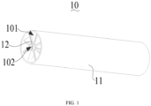
FIG. 1 is a schematic structural view of a heat exchanger according to an embodiment of the present application. -
FIG. 2 is an exploded structural view of the heat exchanger inFIG. 1 . -
FIG. 3 is a schematic structural view of one diversion unit group. -
FIG. 4 is a partial structural view of the diversion unit group inFIG. 3 . -
FIG. 5 is a schematic view of a flow of fluid inside the heat exchanger inFIG. 1 . -
FIG. 6 is a schematic structural view of a dishwasher with a heat pump system. -
Reference sign Name Reference sign Name 10 heat exchanger 123 second hollow vane 11 outer sleeve 124 first central tube 12 diversion unit group 1241 fluid inlet 101 first tortuous flow channel 1242 first through hole 102 second tortuous flow channel 125 second central tube 121 first hollow vane 1251 fluid outlet 122 connecting channel 1252 second through hole 200 dishwasher 24 evaporator 20 heat pump system 25 fan 21 compressor 26 circulating pump 22 condenser 27 cavity sink 23 throttle valve 28 spray arm - The realization of the objective, functional characteristics, and advantages of the present application are further described with reference to the accompanying drawings.
- The technical solutions in the embodiments of the present application will be clearly and completely described below with reference to the drawings in the embodiment of the present application. Obviously, the described embodiments are only a part of the embodiments of the present application, not all of the embodiments. Based on the embodiments in the present application, all other embodiments perceived by those ordinary skills in the art without creative effort should be fallen within the protection scope of the present application.
- It should be noted that all of the directional instructions in the embodiments of the present application (such as, up, down, left, right, front, rear.....) are only used to explain the relative position relationship and movement of each component under a specific attitude (as shown in the drawings), if the specific attitude changes, the directional instructions will change correspondingly.
- Besides, the descriptions in the present application that refer to "first," "second," etc. are only for descriptive purposes and are not to be interpreted as indicating or implying relative importance or to implicitly indicate the number of technical features indicated. Thus, a feature defined as "first" or "second" may explicitly or implicitly include at least one of the features. In addition, the meaning of "and/or" appearing in the whole text includes three parallel solutions. For example, "A and/or B" includes only A, or only B, or both A and B. Furthermore, technical solutions among the embodiments can be combined with each other, but must be based on the realization of the technical solutions by those skilled in the art, and when the technical solutions are contradictory to each other or cannot be realized, the technical solutions should be considered that the combination does not exist, and the technical solutions are not fallen within the protection scope claimed in the present application.
- The present application provides a
heat exchanger 10. - As shown in
FIG. 1 andFIG. 2 , in an embodiment of the present application, theheat exchanger 10 includes anouter sleeve 11 and at least one set ofdiversion unit groups 12. Theouter sleeve 11 is provided with two open ends; thediversion unit group 12 is provided in theouter sleeve 11, a firsttortuous flow channel 101 is formed between theouter sleeve 11 and thediversion unit group 12 for a first fluid to flow from one end to the other end of theouter sleeve 11. Thediversion unit group 12 includes a firsthollow vane 121, a connectingchannel 122 and a secondhollow vane 123 provided in sequence along an axial direction of theouter sleeve 11. The firsthollow vane 121, the connectingchannel 122 and the secondhollow vane 123 are sequentially connected to form a secondtortuous flow channel 102 for the second fluid to flow from one end to the other end of theouter sleeve 11. - In an embodiment, the
outer sleeve 11 is in a hollow tubular shape, and the two ends of theouter sleeve 11 are open. Thediversion unit group 12 is provided in theouter sleeve 11. The firsttortuous flow channel 101 is formed between the inner peripheral surface of theouter sleeve 11 and the outer surface of thediversion unit group 12, so that the first fluid can flow from one end to the other end of theouter sleeve 11 along the firsttortuous flow channel 101. The secondtortuous flow channel 102 is formed inside thediversion unit group 12, and the second fluid can flow from one end to the other end of theouter sleeve 11 along the secondtortuous flow channel 102. For example, in practical applications, the first fluid may be water, and the second fluid may be refrigerant. The water and the refrigerant are provided in reverse flow, that is, water enters the firsttortuous flow channel 101 from the first open end of theouter sleeve 11, and then flows through the firsttortuous flow channel 101 to the second open end of theouter sleeve 11 for output. The refrigerant enters the secondtortuous flow channel 102 from the second open end of theouter sleeve 11, and then passes through the secondtortuous flow channel 102 to the first open end of theouter sleeve 11 for output. The flow directions of water and refrigerant are opposite, with the water and refrigerant flow in the firsttortuous flow channel 101 and the secondtortuous flow channel 102 respectively, and realize heat exchange during flowing. - It should be noted that, in this embodiment, the specific quantity of
diversion unit groups 12 in theouter sleeve 11 can be provided according to actual needs, for example, one, two or more sets ofdiversion unit groups 12 can be provided. As shown inFIG. 2 , there are two sets ofdiversion unit groups 12, which is only an embodiment of the present application, and is not a limitation to the present application. For the convenience of description, only one set ofdiversion unit groups 12 is taken as an example for description below. As shown inFIG. 3 andFIG. 4 , thediversion unit group 12 includes the firsthollow vane 121, the connectingchannel 122 and the secondhollow vane 123 sequentially provided along the axial direction of theouter sleeve 11. The firsthollow vane 121 and the secondhollow vane 123 are in a wide sheet structure, and the connectingchannel 122 is in an elongated tubular structure. One end of the connectingchannel 122 is connected and communicated with the firsthollow vane 121, and the other end of the connectingchannel 122 is connected and communicated with the secondhollow vane 123. The second fluid (such as refrigerant) first enters the firsthollow vane 121, then enters the connectingchannel 122 through the end of the firsthollow vane 121, then flows into the secondhollow vane 123 through the connectingchannel 122, and finally flows out from the secondhollow vane 123. The entire flow path of the second fluid (that is, the second tortuous flow channel 102) is tortuous rather than straight, so the effective length of the flow channel can be extended, and the flow path of the second fluid can be extended. The firsthollow vanes 121 and the secondhollow vanes 123 have a wide sheet structure, which can increase the contact area between the second fluid and the first fluid, thereby improving heat exchange efficiency. - According to the technical solution of the present application, a
diversion unit group 12 is provided in theouter sleeve 11, and thediversion unit group 12 includes a firsthollow vane 121, a connectingchannel 122 and a secondhollow vane 123 sequentially provided along the axial direction of theouter sleeve 11. The firsttortuous flow channel 101 is formed between theouter sleeve 11 and thediversion unit group 12 for the first fluid to flow through. The firsthollow vane 121, the connectingchannel 122 and the secondhollow vane 123 are sequentially connected to form the secondtortuous flow channel 102 for the second fluid to flow through. When theheat exchanger 10 is working, the first fluid (such as water) and the second fluid (such as refrigerant) flow in reverse directions in the firsttortuous flow channel 101 and the secondtortuous flow channel 102 respectively. The firsttortuous flow channel 101 and the secondtortuous flow channel 101 are tortuous structure and are extended from one end to the other end of theouter sleeve 11, so that the effective length of the flow path can be extended as much as possible without increasing the length of theouter sleeve 11, and the effective flow distance of the fluid can be extended. Both the firsthollow vane 121 and the secondhollow vane 123 have a hollow sheet structure, which can effectively increase the contact area between the first fluid and the second fluid, and increase the residence time of the first fluid and the second fluid in the corresponding flow channel. Thus, the heat exchange efficiency can be effectively improved. Therefore, compared with the traditional double-tube heat exchanger, the technical solution of the present application can effectively shorten the overall length of theheat exchanger 10, reduce the overall occupied volume of theheat exchanger 10, and improve heat exchange efficiency. - Further, the first
hollow vane 121, the connectingchannel 122 and the secondhollow vane 123 are twisted and inclined relative to the axis of theouter sleeve 11. Taking the firsthollow vane 121 as an example, the firsthollow vane 121 is twisted and inclined relative to the axis of theouter sleeve 11, that is, the firsthollow vane 121 has a certain twist angle relative to the axis of theouter sleeve 11. The firsthollow vane 121 extends along the axial direction of theouter sleeve 11 and twists along the circumferential direction of theouter sleeve 11, so that the firsthollow vane 121 presents a twisted shape rather than a completely planar structure. Similarly, the secondhollow vane 123 is also twisted and inclined relative to the axis of theouter sleeve 11, so that the secondhollow vane 123 presents a twisted shape rather than a completely planar structure. The connectingchannel 122 is twisted and inclined relative to the axis of theouter sleeve 11, so that the connectingchannel 122 presents a twisted shape rather than a straight-line structure. - In this embodiment, the first
hollow vane 121, the connectingchannel 122 and the secondhollow vane 123 are all in a twisted shape, such that a swirl flow can be generated when the first fluid flows along the firsttortuous flow channel 101 and moves sequentially along the rotation direction of the outer surfaces of the firsthollow vane 121, the connectingchannel 122 and the secondhollow vane 123, which is beneficial to increase the flow length and the residence time of the first fluid, thereby improving the heat exchange efficiency. The flow resistance of the first fluid is also reduced, thereby reducing energy consumption. When the second fluid flows along the secondtortuous flow channel 102, the swirl flow can be generated when the second fluid flows along the secondtortuous flow channel 102 and moves sequentially along the rotation direction of the inner surfaces of the firsthollow vane 121, the connectingchannel 122 and the secondhollow vane 123, which is beneficial to increase the flow length and the residence time of the second fluid, thereby improving the heat exchange efficiency. - Further, the twist and incline direction of the first
hollow vane 121 and the secondhollow vane 123 are the same, and the twist and incline direction of the connectingchannel 122 and the firsthollow vane 121 are opposite. For example, both the firsthollow vane 121 and the secondhollow vane 123 rotate positively relative to the axis of theouter sleeve 11, and the connectingchannel 122 rotates reversely relative to the axis of theouter sleeve 11. It should be noted that the positive rotation and reverse rotation here are only relatively speaking, it shows the different rotation directions. Taking the flow of the first fluid (such as water) as an example, the first fluid flows along the surface of the firsthollow vane 121 to generate swirling flow, and after reaching the end of the firsthollow vane 121, the flow of the first fluid changes suddenly due to the change of the rotation direction of the connectingchannel 122, which is beneficial for the first fluid to scour the outer surface of the connectingchannel 122. The second fluid (such as refrigerant) has a longer residence time when passing through the relatively slender connectingchannel 122. In this way, the convective heat transfer between the first fluid and the second fluid is improved, and the heat exchange efficiency is further improved. - Further, the connecting
channel 122 is attached to the inner wall surface of theouter sleeve 11. When the first fluid scours the outer surface of the connectingchannel 122, a certain impact force will be generated on the connectingchannel 122. The connectingchannel 122 is a slender strip structure, and the connectingchannel 122 is attached to the inner wall of theouter sleeve 11, which improves the structural strength of the connectingchannel 122, prevents the connectingchannel 122 from being broken and damaged under long-term washing, and increases the service life of theheat exchanger 10. In addition, the connectingchannel 122 is attached to the inner wall of theouter sleeve 11, which is also conducive to the integral formation of the connectingchannel 122 and theouter sleeve 11. For example, the connectingchannel 122 can be printed on the inner wall of theouter sleeve 11 by 3D printing technology, which can simplify the production process of theheat exchanger 10 and save costs. - Further, as shown in
FIG. 3 andFIG. 4 , thediversion unit group 12 also includes the firstcentral tube 124 and the secondcentral tube 125. The firsthollow vane 121 is fixed on the outer periphery of the firstcentral tube 124, and one end of the firstcentral tube 124 away from the connectingchannel 122 is provided with afluid inlet 1241. The other end of the firstcentral tube 124 is closed, and the peripheral wall of the firstcentral tube 124 is provided with the first throughhole 1242 communicated with the firsthollow vane 121. The secondhollow vane 123 is fixed on the outer periphery of the secondcentral tube 125, one end of the secondcentral tube 125 away from the connectingchannel 122 is provided with afluid outlet 1251, the other end of the secondcentral tube 125 is closed, and the peripheral wall of the secondcentral tube 125 is provided with the second throughhole 1252 communicated with the secondhollow vane 123. - In an embodiment, the first
central tube 124 is a straight tube extending coaxially with theouter sleeve 11. The firstcentral tube 124 is a hollow tubular structure with an open end and a closed end. One side of the firsthollow vane 121 is attached to the outer peripheral surface of the firstcentral tube 124 and is extended along the firstcentral tube 124. The open end of the firstcentral tube 124 is provided with afluid inlet 1241, the side wall of the firstcentral tube 124 is provided with a first throughhole 1242, the second fluid can flow from thefluid inlet 1241 into the firstcentral tube 124, and then flows into the firsthollow vane 121 through the first throughhole 1242. The secondcentral tube 125 is a straight tube extending coaxially with theouter sleeve 11. The secondcentral tube 125 is a hollow tubular structure with an open and a closed end. One side of the secondhollow vane 123 is attached to the outer periphery of the secondcentral tube 125 and is extended along the secondcentral tube 125. The open end of the secondcentral tube 125 is provided with afluid outlet 1251, and the side wall of the secondcentral tube 125 is provided with a second throughhole 1252. The second fluid can flow from the firsthollow vane 121 into the secondhollow vane 123 through the connectingchannel 122, then flows into the secondcentral tube 125 through the second throughhole 1252 from the secondhollow vane 123, and finally flows out from thefluid outlet 1251 of the secondcentral tube 125. - Further, in one
diversion unit group 12, the plurality of the firsthollow vanes 121, the connectingchannels 122 and the secondhollow vanes 123 are provided in a one-to-one correspondence. Each of the firsthollow vanes 121 is spaced apart along the circumferential direction of the firstcentral tube 124, and the peripheral wall of the firstcentral tube 124 is provided with the plurality of first throughholes 1242 along the circumferential direction. The first throughholes 1242 and the firsthollow vanes 121 are communicated in a one-to-one correspondence. Each of the secondhollow vanes 123 is spaced apart along the circumferential direction of the secondcentral tube 125, and the peripheral wall of the secondcentral tube 125 is provided with a plurality of the second throughholes 1252 along the circumferential direction. The second throughholes 1252 and the secondhollow vanes 123 are communicated in a one-to-one correspondence. Each of the connectingchannels 122 is connected between the firsthollow vane 121 and the secondhollow vane 123 in a one-to-one correspondence. - In an embodiment, a plurality of first
hollow vanes 121 are spaced apart along the circumferential direction of the firstcentral tube 124, a plurality of secondhollow vanes 123 are spaced apart along the circumferential direction of the secondcentral tube 125, and a plurality of connectingchannels 122 are spaced apart along the inner peripheral surface of theouter sleeve 11. One end of each connectingchannel 122 is connected and communicated with the end of the firsthollow vane 121 close to the inner wall surface of theouter sleeve 11, and the other end of each connectingchannel 122 is connected and communicated with the end of the secondhollow vane 123 close to the inner wall surface of theouter sleeve 11. A first channel is formed between any two adjacent firsthollow vanes 121, a second channel is formed between any adjacent two secondhollow vanes 123, and an intermediate channel is formed between the plurality of connectingchannels 122. - The flow path of the first fluid along the first
tortuous flow channel 101 is generally as follows. The first fluid enters the first channel from one end of theouter sleeve 11, then enters the middle channel from the first channel, and then enters the third channel from the middle channel. The flow path of the second fluid along the secondtortuous flow channel 102 is generally as follows. The second fluid enters the firstcentral tube 124 from thefluid inlet 1241 of the firstcentral tube 124, and then passes through the plurality of first throughhole 1242 on the side wall of the firstcentral tube 124 to flow into the corresponding firsthollow vane 121. Then, the second fluid enters into the corresponding connectingchannel 122 at the end of each firsthollow vane 121 close to the inner wall surface of theouter sleeve 11, and then enters the secondhollow vane 123 through the connectingchannel 122. The second fluid finally flows into the secondcentral tube 125 through a plurality of second throughholes 1252 on the outer peripheral surface of the secondcentral tube 125, and then flows out from thefluid outlet 1251 of the secondcentral tube 125. When entering the plurality of firsthollow vanes 121 through the firstcentral tube 124, the second fluid undergoes divergent movement in a centrifugal direction. When entering the secondcentral tube 125 from the plurality of secondhollow vanes 123, the second fluid undergoes convergent movement in a centripetal direction. The above design can further increase the contact area between the first fluid and the second fluid, prolong the flow and residence time of the first fluid and the second fluid in the corresponding flow channel, and improve the heat exchange efficiency. - Further, both the first
central tube 124 and the secondcentral tube 125 are straight tubes extending coaxially with theouter sleeve 11, and a plurality of the firsthollow vanes 121 are evenly distributed at intervals along the circumferential direction of the firstcentral tube 124. The plurality of secondhollow vanes 123 are evenly distributed at intervals along the circumferential direction of the secondcentral tube 125. In this way, on the same circumferential section, the spacing between any two adjacent firsthollow vanes 121 is equal, and the spacing between any adjacent two secondhollow vanes 123 is equal, so that the flow distribution of the first fluid and the second fluid is more uniform and the heat exchange between the first fluid and the second fluid is more uniform. - Further, on the basis of the above embodiments, at least two
diversion unit groups 12 are provided, and eachdiversion unit group 12 is provided in an array along the axial direction of theouter sleeve 11 and communicates with each other in sequence. In this way, after the second fluid flows through the secondtortuous flow channel 102 of the first group ofdiversion unit groups 12, it can immediately enter the secondtortuous flow channel 102 of the next group ofdiversion unit groups 12, so that the flow path of the second fluid can be further improved, and thus a better heat transfer effect can be achieved. - As shown in
FIG. 1 andFIG. 2 , in an embodiment, theheat exchanger 10 includes anouter sleeve 11 and at least twodiversion unit groups 12 provided in theouter sleeve 11, and eachdiversion unit group 12 includes a firstcentral tube 124, a plurality of firsthollow vanes 121, a plurality of connectingchannels 122, a plurality of secondhollow vanes 123, and a secondcentral tube 125. A plurality of the firsthollow vanes 121 are spaced and evenly distributed along the circumferential direction of the firstcentral tube 124, a plurality of secondhollow vanes 123 are spaced and evenly distributed along the circumferential direction of the secondcentral tube 125, and a plurality of connectingchannels 122 are attached to each other. The inner peripheral surface of theouter sleeve 11 is spaced and uniformly provided, and one end of each connectingchannel 122 is connected and communicated with the firsthollow vane 121, and the other end of each connectingchannel 122 is connected and communicated with the secondhollow vane 123. The firsthollow vane 121, the connectingchannel 122 and the secondhollow vane 123 are twisted and inclined relative to the axis of theouter sleeve 11. The firsthollow vane 121 and the secondhollow vane 123 have the same twist and incline direction, and the connectingchannel 122 and the firsthollow vane 121 and the secondhollow vane 123 have the opposite twist and incline direction. - In an embodiment, as shown in
FIG. 1 andFIG. 5 , the first fluid (such as water) enters the first channel between any two adjacent firsthollow vanes 121 through an opening of theouter sleeve 11, and then passes through a plurality of the first channel to converge to the middle channel defined by the plurality of connectingchannels 122, and then diverges to the second channel between any two adjacent secondhollow vanes 123 through the middle channel, and finally flows out from another opening of theouter sleeve 11. A flow direction of the second fluid is opposite to the flow direction of the first fluid. The second fluid (such as refrigerant) enters the firstcentral tube 124 from thefluid inlet 1241 of the firstcentral tube 124, and then passes through a plurality of the first throughholes 1242 on the side wall of the firstcentral tube 124 to diverge into the corresponding firsthollow vane 121 and undergoes a divergent movement in the centrifugal direction in the firsthollow vane 121. Then, the second fluid enters the corresponding connectingchannel 122 from the end of each firsthollow vane 121 close to the inner wall surface of theouter sleeve 11, and then enters the secondhollow vane 123 through the connectingchannel 122 and undergoes the convergent movement in the centripetal direction in the secondhollow vane 123. Finally, the second fluid passes through the plurality of second throughholes 1252 of the outer peripheral surface of the secondcentral tube 125 to converge into the secondcentral tube 125, and then flow out from thefluid outlet 1251 of the secondcentral tube 125 into the nextdiversion unit group 12. - In this embodiment, the first
hollow vane 121 and the secondhollow vane 123 have a sheet structure, which can increase the contact area between the first fluid and the second fluid and improve the heat exchange efficiency. The firsthollow vane 121 and the secondhollow vane 123 are in a twisted structure, which can induce the first fluid and the second fluid to generate swirling flow. This is beneficial for increasing the flow path of the first fluid and the second fluid, prolonging the residence time, and further enhancing the heat exchange efficiency. Additionally, it also reduces the flow resistance of the first fluid, thereby reducing energy consumption. The firsthollow vane 121 and the secondhollow vane 123 rotate in opposite directions to the connectingchannel 122, which is beneficial for the first fluid to scour the connectingchannel 122, thereby improving convective heat transfer. Generally speaking, compared with the traditional double-tube heat exchanger, under the condition of achieving the same heat exchange effect, the overall length of theheat exchanger 10 of the present technical solution is shorter, and the occupied volume is smaller, which is beneficial to the miniaturization of theheat pump system 20. - As shown in
FIG. 6 , the present application further provides aheat pump system 20. In an embodiment, theheat pump system 20 includes acompressor 21, acondenser 22, athrottle valve 23, and anevaporator 24. Thecompressor 21, thecondenser 22, thethrottle valve 23 and theevaporator 24 are communicated with each other to form a circulation circuit, and thecondenser 22 adopts theheat exchanger 10 as described above. - The
heat pump system 20 of this solution adopts the above-mentionedheat exchanger 10 as thecondenser 22. Theheat exchanger 10 includes anouter sleeve 11 and adiversion unit group 12. Theouter sleeve 11 is provided with two open ends, thediversion unit group 12 is provided in theouter sleeve 11, and a firsttortuous flow channel 101 is formed between theouter sleeve 11 and thediversion unit group 12 for the first fluid to flow through from one end to the other end of theouter sleeve 11. Thediversion unit group 12 includes a firsthollow vane 121, a connectingchannel 122 and a secondhollow vane 123 sequentially provided along an axial direction of theouter sleeve 11. The firsthollow vane 121, the connectingchannel 122 and the secondhollow vane 122 are sequentially connected to form the secondtortuous flow channel 102 for the second fluid to flow from one end to the other end of theouter sleeve 11. Compared with the traditional double-tube heat exchanger, in the case of achieving the same heat exchange effect, the overall length of theheat exchanger 10 of this solution is smaller, and the occupied volume is smaller, thereby making the overallheat pump system 20 more compact, smaller in size, and higher in heat exchange efficiency. The specific structure of theheat exchanger 10 refers to the above-mentioned embodiments. Since theheat pump system 20 adopts all the technical solutions of all the above-mentioned embodiments, it at least possesses all the beneficial effects brought by the technical solutions of the above-mentioned embodiments, which will not be repeated here. - Further, the
heat pump system 20 includes a plurality of the condensers 22 (heat exchangers 10), and the plurality ofcondensers 22 are connected to the circulation circuit of theheat pump system 20 in parallel. In this way, eachcondenser 22 can be controlled independently, and different quantities of thecondensers 22 can be controlled to work according to actual heat exchange needs. In addition, the plurality ofcondensers 22 are connected in parallel without increasing the overall length of theheat pump system 20, so that theheat pump system 20 can maintain a small length while having an efficient heat exchange function. - As shown in
FIG. 6 , the present application further provides adishwasher 200. In an embodiment, thedishwasher 200 includes a body and aheat pump system 20 provided in the body. Theheat pump system 20 includes acompressor 21, acondenser 22, athrottle valve 23 and anevaporator 24. Thecompressor 21, thecondenser 22, thethrottle valve 23 and theevaporator 24 are communicated with each other to form a circulation circuit, and thecondenser 22 adopts theheat exchanger 10 as described above. Theheat exchanger 10 includes anouter sleeve 11 and adiversion unit group 12. Theouter sleeve 11 is provided with two open ends, thediversion unit group 12 is provided in theouter sleeve 11, and a firsttortuous flow channel 101 is formed between theouter sleeve 11 and thediversion unit group 12 for the first fluid to flow through from one end to the other end of theouter sleeve 11. Thediversion unit group 12 includes a firsthollow vane 121, a connectingchannel 122 and a secondhollow vane 123 sequentially provided along an axial direction of theouter sleeve 11. The firsthollow vane 121, the connectingchannel 122 and the secondhollow vane 122 are sequentially connected to form the secondtortuous flow channel 102 for the second fluid to flow from one end to the other end of theouter sleeve 11. - In an embodiment, as shown in
FIG. 6 , theheat pump system 20 is concentrated in the chassis of thedishwasher 200. Theheat pump system 20 includes acompressor 21, acondenser 22, athrottle valve 23 and anevaporator 24, and thecondenser 22 adopts the above-mentionedheat exchanger 10. The refrigerant channel (that is, the secondtortuous flow channel 102 of the heat exchanger 10) of the condenser 22 (that is, the heat exchanger 10) is sequentially connected to thethrottle valve 23, theevaporator 24 and thecompressor 21 to form a circulation circuit for the refrigerant to flow. The outlet end of the water channel (that is, the firsttortuous flow channel 101 of the heat exchanger 10) of the condenser 22 (that is, the heat exchanger 10) is connected to the water inlet of the circulatingwater pump 26, and the inlet end of the water channel is connected to the water return port of thecavity sink 27, and the water outlet of the circulatingwater pump 26 is connected to thespray arm 28 in the inner cavity of thedishwasher 200 through a pipeline. The quantity ofspray arms 28 can be one, two or more according to actual needs. - When the
dishwasher 200 works normally, the circulatingwater pump 26 provides power to drive circulating water for cleaning. The circulatingwater pump 26 pumps hot water into thespray arm 28 through the pipeline. Thespray arm 28 is located in the inner cavity of the body. The hot water is sprayed on the tableware through a plurality of spray holes, and finally the hot water enters thecavity sink 27 for collection by gravity, and flows out from the water return port and enters the circulatingwater pump 26 through thecondenser 22. Thecondenser 22 used in theheat pump system 20 is located between the water return port and the circulatingwater pump 26. One side of thecondenser 22 is a water channel, and the other side of thecondenser 22 is a refrigerant channel. The water heating process is completed in thecondenser 22. Thecondenser 22 can specifically be theheat exchanger 10 adopted in the above-mentioned embodiment. Thecondenser 22 is the high temperature side of theheat pump system 20, used to transfer the heat of the refrigerant to water. The low temperature side of theheat pump system 20 is theevaporator 24, used for heat exchange between the refrigerant and the air. In an embodiment, theheat pump system 20 further includes afan 25 located at the inner side of theevaporator 24. Thefan 25 can specifically be an axial-flow fan. The components of the entireheat pump system 20 are separated by afan 25. One side of thefan 25 is thecondenser 22 and thecompressor 21, which are closer to the circulatingwater pump 26 for easy connection to the water pipes. The other side of thefan 25 is theevaporator 24 and the air duct, which are located at the front side of the chassis, and is convenient to complete heat exchange with the air. The air inlet of thefan 25 is connected to the air inlet duct, the air outlet of thefan 25 is connected to the air outlet duct, and the other end of the air inlet duct is theevaporator 24. When exchanging heat with air, all the air enters the air inlet duct after passing through theevaporator 24, then enters thefan 25, and finally flows out from the air outlet duct. The air inlet and the air outlet are all at the front side of the chassis. Thedishwasher 200 of this solution adopts the above-mentionedheat pump system 20, and theheat pump system 20 has a compact overall layout and occupies little space, so that theoverall dishwasher 200 can be made more compact and smaller. The specific structure of theheat exchanger 10 refers to the above-mentioned embodiments. Since thedishwasher 200 adopts all the technical solutions of all the above-mentioned embodiments, it at least possesses all the beneficial effects brought by the technical solutions of the above-mentioned embodiments, which is not repeated here. - The above are only some embodiments of the present application, and are not intended to limit the scope of the present application. Under the inventive concept of the present application, the equivalent structural transformations made by using the description of the application and the contents of the accompanying drawings, or direct/indirect applications in other relevant technical fields are included in the scope of the present application.
Claims (10)
- A heat exchanger, characterized by comprising:an outer sleeve provided with two open ends; andat least one diversion unit group provided in the outer sleeve,wherein:a first tortuous flow channel is formed between the outer sleeve and the diversion unit group for a first fluid to flow from one end to the other end of the outer sleeve,the diversion unit group comprises a first hollow vane, a connecting channel, and a second hollow vane sequentially provided along an axial direction of the outer sleeve, andthe first hollow vane, the connecting channel and the second hollow vane are sequentially connected to form a second tortuous flow channel for a second fluid to flow from one end to the other end of the outer sleeve.
- The heat exchanger according to claim 1, wherein the first hollow vane, the connecting channel, and the second hollow vane are twisted and inclined relative to an axis of the outer sleeve.
- The heat exchanger according to claim 2, wherein a twist and incline direction of the first hollow vane and the second hollow vane are the same, and a twist and incline direction of the connecting channel and the first hollow vane are opposite.
- The heat exchanger according to claim 1, wherein the connecting channel is attached to an inner wall surface of the outer sleeve.
- The heat exchanger according to claim 1, wherein:the diversion unit group further comprises a first central tube and a second central tube,the first hollow vane is fixed on an outer periphery of the first central tube, one end of the first central tube away from the connecting channel is provided with a fluid inlet, the other end of the first central tube is closed, and a peripheral wall of the first central tube is provided with a first through hole communicated with the first hollow vane, andthe second hollow vane is fixed on an outer periphery of the second central tube, one end of the second central tube away from the connecting channel is provided with a fluid outlet, the other end of the second central tube is closed, and a peripheral wall of the second central tube is provided with a second through hole communicated with the second hollow vane.
- The heat exchanger according to claim 5, wherein:in one diversion unit group, a plurality of the first hollow vanes, the connecting channels and the second hollow vanes are provided in a one-to-one correspondence,each of the first hollow vanes is spaced apart along a circumferential direction of the first central tube, the peripheral wall of the first central tube is provided with a plurality of the first through holes along the circumferential direction, and the first through holes and the first hollow vanes are communicated in a one-to-one correspondence,each of the second hollow vanes is spaced apart along a circumferential direction of the second central tube, and the peripheral wall of the second central tube is provided with a plurality of the second through holes along the circumferential direction, the second through holes and the second hollow vanes are communicated in a one-to-one correspondence, andeach of the connecting channels is connected between the first hollow vane and the second hollow vane in a one-to-one correspondence.
- The heat exchanger according to claim 6, wherein both the first central tube and the second central tube are straight tubes extending coaxially with the outer sleeve, a plurality of the first hollow vanes are evenly spaced apart along the circumferential direction of the first central tube, and the plurality of second hollow vanes are evenly spaced apart along the circumferential direction of the second central tube.
- The heat exchanger according to any one of claims 1 to 7, wherein at least two diversion unit groups are provided, and each group of the diversion unit groups is provided along the axial direction of the outer sleeve and communicated sequentially.
- A heat pump system, characterized by comprising:a compressor;a condenser;a throttle valve; andan evaporator,wherein the compressor, the condenser, the throttle valve, and the evaporator are communicated with each other to form a circulation circuit, and the condenser adopts the heat exchanger according to any one of claims 1 to 8.
- A dishwasher, characterized by comprising the heat pump system according to claim 9.
Applications Claiming Priority (2)
| Application Number | Priority Date | Filing Date | Title |
|---|---|---|---|
| CN202111418336.6A CN114061335B (en) | 2021-11-24 | 2021-11-24 | Heat exchangers, heat pump systems and dishwashers |
| PCT/CN2022/122242 WO2023093287A1 (en) | 2021-11-24 | 2022-09-28 | Heat exchanger, heat pump system and dishwasher |
Publications (3)
| Publication Number | Publication Date |
|---|---|
| EP4283237A1 true EP4283237A1 (en) | 2023-11-29 |
| EP4283237A4 EP4283237A4 (en) | 2024-08-21 |
| EP4283237B1 EP4283237B1 (en) | 2025-08-13 |
Family
ID=80276489
Family Applications (1)
| Application Number | Title | Priority Date | Filing Date |
|---|---|---|---|
| EP22897373.1A Active EP4283237B1 (en) | 2021-11-24 | 2022-09-28 | Heat pump system and dishwasher |
Country Status (4)
| Country | Link |
|---|---|
| US (1) | US12535274B2 (en) |
| EP (1) | EP4283237B1 (en) |
| CN (1) | CN114061335B (en) |
| WO (1) | WO2023093287A1 (en) |
Cited By (1)
| Publication number | Priority date | Publication date | Assignee | Title |
|---|---|---|---|---|
| WO2025031926A1 (en) * | 2023-08-08 | 2025-02-13 | BSH Hausgeräte GmbH | Dishwasher having a heat-pump arrangement, and heat-transfer device for same |
Families Citing this family (2)
| Publication number | Priority date | Publication date | Assignee | Title |
|---|---|---|---|---|
| CN114061335B (en) * | 2021-11-24 | 2023-07-28 | 广东美的白色家电技术创新中心有限公司 | Heat exchangers, heat pump systems and dishwashers |
| CN115264712B (en) * | 2022-07-04 | 2023-08-04 | 臧蕙心 | New fan |
Family Cites Families (23)
| Publication number | Priority date | Publication date | Assignee | Title |
|---|---|---|---|---|
| US342871A (en) * | 1886-06-01 | hooking | ||
| GB219329A (en) * | 1923-07-18 | 1925-10-19 | Adolf Pfoser | Improvements in or relating to tubular heat-exchange apparatus |
| AT266887B (en) * | 1964-04-06 | 1968-12-10 | Waagner Biro Ag | Heat exchanger |
| FR2627265B1 (en) * | 1988-02-17 | 1990-04-27 | Fradin Jean | COMPACT HEAT EXCHANGER |
| JPH01230994A (en) * | 1988-03-09 | 1989-09-14 | Matsushita Seiko Co Ltd | Rotary type heat exchanger |
| CN2657750Y (en) * | 2003-07-09 | 2004-11-24 | 姜向前 | Cooling crystallization tank |
| WO2008113604A1 (en) * | 2007-03-21 | 2008-09-25 | Frank & Krah Wickelrohr Gmbh | Tubular hollow profile and the use thereof |
| CN101566437B (en) * | 2008-04-26 | 2013-07-10 | 赵文阁 | Composite sleeve double-helix heat exchanger |
| CN101738110B (en) * | 2010-01-21 | 2011-06-29 | 上海交通大学 | Tube-and-tube heat exchanger with offset expansion on both sides of the deflected fins |
| JP6026838B2 (en) * | 2012-10-02 | 2016-11-16 | 株式会社フジクラ | Loop type heat pipe |
| CN103070656B (en) * | 2013-01-23 | 2015-01-07 | 林贤华 | Dish washing machine based on heating and drying of heat pump |
| EP3117169B1 (en) * | 2014-03-13 | 2018-05-09 | BAE Systems PLC | Heat exchanger |
| CN105258533B (en) * | 2015-11-17 | 2017-03-01 | 中国科学院上海高等研究院 | There is the shell-and-tube heat exchanger of fractal structure |
| US11015878B2 (en) * | 2015-12-16 | 2021-05-25 | Carrier Corporation | Heat transfer tube for heat exchanger |
| TW201807305A (en) * | 2016-08-23 | 2018-03-01 | 黃國彰 | Flow vane device wherein the outer edge of the impeller base is spaced from the ribs to define a gap that matches the particle size distribution of sandstones, thus enabling sandstones in the fluid to pass through the gap correspondingly to avoid abrasions |
| CN106949766A (en) * | 2017-01-16 | 2017-07-14 | 付占江 | Hollow blade rotator type heat exchanger |
| CN207095362U (en) * | 2017-08-03 | 2018-03-13 | 武汉帕浦安科技有限公司 | A kind of jacketed type exchanger |
| CN207907416U (en) * | 2018-05-24 | 2018-09-25 | 英特换热设备(浙江)有限公司 | A kind of minitype air conditioner all-in-one machine |
| US10935332B2 (en) * | 2018-08-09 | 2021-03-02 | Rheem Manufacturing Company | Fluid flow guide insert for heat exchanger tubes |
| CN110174009A (en) * | 2019-06-12 | 2019-08-27 | 珠海格力电器股份有限公司 | Double-pipe heat exchanger with fins |
| US11680736B2 (en) * | 2019-11-19 | 2023-06-20 | Melink Solar & Geo, Inc. | Heat pump system utilizing domestic water |
| US20210180870A1 (en) * | 2019-12-12 | 2021-06-17 | Saint-Gobain Ceramics & Plastics, Inc. | Heat exchanger component with varying twist angle |
| CN114061335B (en) * | 2021-11-24 | 2023-07-28 | 广东美的白色家电技术创新中心有限公司 | Heat exchangers, heat pump systems and dishwashers |
-
2021
- 2021-11-24 CN CN202111418336.6A patent/CN114061335B/en active Active
-
2022
- 2022-09-28 WO PCT/CN2022/122242 patent/WO2023093287A1/en not_active Ceased
- 2022-09-28 EP EP22897373.1A patent/EP4283237B1/en active Active
-
2023
- 2023-09-18 US US18/369,669 patent/US12535274B2/en active Active
Cited By (1)
| Publication number | Priority date | Publication date | Assignee | Title |
|---|---|---|---|---|
| WO2025031926A1 (en) * | 2023-08-08 | 2025-02-13 | BSH Hausgeräte GmbH | Dishwasher having a heat-pump arrangement, and heat-transfer device for same |
Also Published As
| Publication number | Publication date |
|---|---|
| US12535274B2 (en) | 2026-01-27 |
| WO2023093287A1 (en) | 2023-06-01 |
| CN114061335A (en) | 2022-02-18 |
| CN114061335B (en) | 2023-07-28 |
| US20240003632A1 (en) | 2024-01-04 |
| EP4283237B1 (en) | 2025-08-13 |
| EP4283237A4 (en) | 2024-08-21 |
Similar Documents
| Publication | Publication Date | Title |
|---|---|---|
| EP4283237A1 (en) | Heat exchanger, heat pump system and dishwasher | |
| CN205843131U (en) | A kind of heat pump is with coaxial bushing pipe heat exchanger | |
| CN101349523B (en) | Step ladder dish-shaped reinforced thermal transmission fin | |
| CN217358209U (en) | Hairpin pipe, heat exchange structure and air conditioner | |
| CN107763832A (en) | Indoor heat exchanger, indoor apparatus of air conditioner and air conditioner | |
| CN107830658A (en) | Heat exchanger, indoor set and air conditioner | |
| CN107763833B (en) | Indoor heat exchanger, air conditioner indoor unit and air conditioner | |
| CN222718736U (en) | Heat exchange device, evaporator and condenser | |
| CN202254497U (en) | Heat exchanger | |
| CN221527469U (en) | Microchannel heat exchanger, heat pump refrigeration system and clothes dryer | |
| CN210861409U (en) | Heat exchanger assembly and air conditioner indoor unit having the same | |
| CN207438860U (en) | Indoor heat exchanger, air conditioner indoor unit and air conditioner | |
| CN215260159U (en) | Heat exchanger assembly and air conditioner indoor unit having the same | |
| CN207622587U (en) | Vapor liquid heat exchange device | |
| CN209978658U (en) | Shell and tube heat exchanger and air conditioning unit | |
| CN212567065U (en) | Heat exchange tube of air conditioner heat exchanger, air conditioner heat exchanger and air conditioning equipment | |
| CN207438858U (en) | Indoor heat exchanger, air conditioner indoor unit and air conditioner | |
| CN106839529A (en) | Evaporator flow passage structure, evaporator, air conditioner room unit and air-conditioner | |
| CN107843029A (en) | Indoor heat exchanger, indoor apparatus of air conditioner and air conditioner | |
| CN209961013U (en) | Torsion tube type convection radiator | |
| CN209310134U (en) | Air conditioner indoor unit and air conditioner | |
| CN209541030U (en) | Air conditioner indoor unit and air conditioner | |
| CN114440665A (en) | Heat Exchangers and Gas Heating Water Heaters | |
| CN208011905U (en) | New type heat exchanger, wall-hanging air conditioner indoor unit and air conditioner | |
| CN207688313U (en) | Dehumidifier |
Legal Events
| Date | Code | Title | Description |
|---|---|---|---|
| STAA | Information on the status of an ep patent application or granted ep patent |
Free format text: STATUS: THE INTERNATIONAL PUBLICATION HAS BEEN MADE |
|
| PUAI | Public reference made under article 153(3) epc to a published international application that has entered the european phase |
Free format text: ORIGINAL CODE: 0009012 |
|
| STAA | Information on the status of an ep patent application or granted ep patent |
Free format text: STATUS: REQUEST FOR EXAMINATION WAS MADE |
|
| 17P | Request for examination filed |
Effective date: 20230822 |
|
| AK | Designated contracting states |
Kind code of ref document: A1 Designated state(s): AL AT BE BG CH CY CZ DE DK EE ES FI FR GB GR HR HU IE IS IT LI LT LU LV MC MK MT NL NO PL PT RO RS SE SI SK SM TR |
|
| A4 | Supplementary search report drawn up and despatched |
Effective date: 20240724 |
|
| RIC1 | Information provided on ipc code assigned before grant |
Ipc: F28F 1/38 20060101ALI20240718BHEP Ipc: F28D 7/10 20060101ALI20240718BHEP Ipc: F28F 1/34 20060101ALI20240718BHEP Ipc: F28D 21/00 20060101ALI20240718BHEP Ipc: A47L 15/42 20060101ALI20240718BHEP Ipc: F28F 13/12 20060101ALI20240718BHEP Ipc: F28F 1/40 20060101ALI20240718BHEP Ipc: F28D 7/02 20060101ALI20240718BHEP Ipc: F25B 39/04 20060101ALI20240718BHEP Ipc: F28F 13/08 20060101ALI20240718BHEP Ipc: F28D 7/00 20060101AFI20240718BHEP |
|
| DAV | Request for validation of the european patent (deleted) | ||
| DAX | Request for extension of the european patent (deleted) | ||
| GRAP | Despatch of communication of intention to grant a patent |
Free format text: ORIGINAL CODE: EPIDOSNIGR1 |
|
| STAA | Information on the status of an ep patent application or granted ep patent |
Free format text: STATUS: GRANT OF PATENT IS INTENDED |
|
| GRAS | Grant fee paid |
Free format text: ORIGINAL CODE: EPIDOSNIGR3 |
|
| INTG | Intention to grant announced |
Effective date: 20250605 |
|
| GRAA | (expected) grant |
Free format text: ORIGINAL CODE: 0009210 |
|
| STAA | Information on the status of an ep patent application or granted ep patent |
Free format text: STATUS: THE PATENT HAS BEEN GRANTED |
|
| AK | Designated contracting states |
Kind code of ref document: B1 Designated state(s): AL AT BE BG CH CY CZ DE DK EE ES FI FR GB GR HR HU IE IS IT LI LT LU LV MC MK MT NL NO PL PT RO RS SE SI SK SM TR |
|
| REG | Reference to a national code |
Ref country code: GB Ref legal event code: FG4D |
|
| REG | Reference to a national code |
Ref country code: CH Ref legal event code: EP |
|
| REG | Reference to a national code |
Ref country code: DE Ref legal event code: R096 Ref document number: 602022019603 Country of ref document: DE |
|
| REG | Reference to a national code |
Ref country code: IE Ref legal event code: FG4D |
|
| PGFP | Annual fee paid to national office [announced via postgrant information from national office to epo] |
Ref country code: DE Payment date: 20250923 Year of fee payment: 4 |
|
| PGFP | Annual fee paid to national office [announced via postgrant information from national office to epo] |
Ref country code: FR Payment date: 20250915 Year of fee payment: 4 Ref country code: AT Payment date: 20251020 Year of fee payment: 4 |
|
| REG | Reference to a national code |
Ref country code: NL Ref legal event code: MP Effective date: 20250813 |
|
| PG25 | Lapsed in a contracting state [announced via postgrant information from national office to epo] |
Ref country code: IS Free format text: LAPSE BECAUSE OF FAILURE TO SUBMIT A TRANSLATION OF THE DESCRIPTION OR TO PAY THE FEE WITHIN THE PRESCRIBED TIME-LIMIT Effective date: 20251213 |
|
| PG25 | Lapsed in a contracting state [announced via postgrant information from national office to epo] |
Ref country code: NO Free format text: LAPSE BECAUSE OF FAILURE TO SUBMIT A TRANSLATION OF THE DESCRIPTION OR TO PAY THE FEE WITHIN THE PRESCRIBED TIME-LIMIT Effective date: 20251113 |
|
| REG | Reference to a national code |
Ref country code: LT Ref legal event code: MG9D |
|
| PG25 | Lapsed in a contracting state [announced via postgrant information from national office to epo] |
Ref country code: PT Free format text: LAPSE BECAUSE OF FAILURE TO SUBMIT A TRANSLATION OF THE DESCRIPTION OR TO PAY THE FEE WITHIN THE PRESCRIBED TIME-LIMIT Effective date: 20251215 |
|
| PG25 | Lapsed in a contracting state [announced via postgrant information from national office to epo] |
Ref country code: FI Free format text: LAPSE BECAUSE OF FAILURE TO SUBMIT A TRANSLATION OF THE DESCRIPTION OR TO PAY THE FEE WITHIN THE PRESCRIBED TIME-LIMIT Effective date: 20250813 |
|
| PG25 | Lapsed in a contracting state [announced via postgrant information from national office to epo] |
Ref country code: HR Free format text: LAPSE BECAUSE OF FAILURE TO SUBMIT A TRANSLATION OF THE DESCRIPTION OR TO PAY THE FEE WITHIN THE PRESCRIBED TIME-LIMIT Effective date: 20250813 Ref country code: NL Free format text: LAPSE BECAUSE OF FAILURE TO SUBMIT A TRANSLATION OF THE DESCRIPTION OR TO PAY THE FEE WITHIN THE PRESCRIBED TIME-LIMIT Effective date: 20250813 |
|
| PG25 | Lapsed in a contracting state [announced via postgrant information from national office to epo] |
Ref country code: GR Free format text: LAPSE BECAUSE OF FAILURE TO SUBMIT A TRANSLATION OF THE DESCRIPTION OR TO PAY THE FEE WITHIN THE PRESCRIBED TIME-LIMIT Effective date: 20251114 |
|
| PG25 | Lapsed in a contracting state [announced via postgrant information from national office to epo] |
Ref country code: SE Free format text: LAPSE BECAUSE OF FAILURE TO SUBMIT A TRANSLATION OF THE DESCRIPTION OR TO PAY THE FEE WITHIN THE PRESCRIBED TIME-LIMIT Effective date: 20250813 |
|
| PG25 | Lapsed in a contracting state [announced via postgrant information from national office to epo] |
Ref country code: LV Free format text: LAPSE BECAUSE OF FAILURE TO SUBMIT A TRANSLATION OF THE DESCRIPTION OR TO PAY THE FEE WITHIN THE PRESCRIBED TIME-LIMIT Effective date: 20250813 |
|
| PG25 | Lapsed in a contracting state [announced via postgrant information from national office to epo] |
Ref country code: PL Free format text: LAPSE BECAUSE OF FAILURE TO SUBMIT A TRANSLATION OF THE DESCRIPTION OR TO PAY THE FEE WITHIN THE PRESCRIBED TIME-LIMIT Effective date: 20250813 Ref country code: BG Free format text: LAPSE BECAUSE OF FAILURE TO SUBMIT A TRANSLATION OF THE DESCRIPTION OR TO PAY THE FEE WITHIN THE PRESCRIBED TIME-LIMIT Effective date: 20250813 |
|
| PG25 | Lapsed in a contracting state [announced via postgrant information from national office to epo] |
Ref country code: RS Free format text: LAPSE BECAUSE OF FAILURE TO SUBMIT A TRANSLATION OF THE DESCRIPTION OR TO PAY THE FEE WITHIN THE PRESCRIBED TIME-LIMIT Effective date: 20251113 |
|
| PG25 | Lapsed in a contracting state [announced via postgrant information from national office to epo] |
Ref country code: ES Free format text: LAPSE BECAUSE OF FAILURE TO SUBMIT A TRANSLATION OF THE DESCRIPTION OR TO PAY THE FEE WITHIN THE PRESCRIBED TIME-LIMIT Effective date: 20250813 |
|
| REG | Reference to a national code |
Ref country code: AT Ref legal event code: MK05 Ref document number: 1825055 Country of ref document: AT Kind code of ref document: T Effective date: 20250813 |
|
| PG25 | Lapsed in a contracting state [announced via postgrant information from national office to epo] |
Ref country code: RO Free format text: LAPSE BECAUSE OF FAILURE TO SUBMIT A TRANSLATION OF THE DESCRIPTION OR TO PAY THE FEE WITHIN THE PRESCRIBED TIME-LIMIT Effective date: 20250813 |
|
| PG25 | Lapsed in a contracting state [announced via postgrant information from national office to epo] |
Ref country code: SM Free format text: LAPSE BECAUSE OF FAILURE TO SUBMIT A TRANSLATION OF THE DESCRIPTION OR TO PAY THE FEE WITHIN THE PRESCRIBED TIME-LIMIT Effective date: 20250813 |
|
| PG25 | Lapsed in a contracting state [announced via postgrant information from national office to epo] |
Ref country code: DK Free format text: LAPSE BECAUSE OF FAILURE TO SUBMIT A TRANSLATION OF THE DESCRIPTION OR TO PAY THE FEE WITHIN THE PRESCRIBED TIME-LIMIT Effective date: 20250813 |
|
| PG25 | Lapsed in a contracting state [announced via postgrant information from national office to epo] |
Ref country code: AT Free format text: LAPSE BECAUSE OF FAILURE TO SUBMIT A TRANSLATION OF THE DESCRIPTION OR TO PAY THE FEE WITHIN THE PRESCRIBED TIME-LIMIT Effective date: 20250813 |
|
| PG25 | Lapsed in a contracting state [announced via postgrant information from national office to epo] |
Ref country code: IT Free format text: LAPSE BECAUSE OF FAILURE TO SUBMIT A TRANSLATION OF THE DESCRIPTION OR TO PAY THE FEE WITHIN THE PRESCRIBED TIME-LIMIT Effective date: 20250813 |
|
| PG25 | Lapsed in a contracting state [announced via postgrant information from national office to epo] |
Ref country code: CZ Free format text: LAPSE BECAUSE OF FAILURE TO SUBMIT A TRANSLATION OF THE DESCRIPTION OR TO PAY THE FEE WITHIN THE PRESCRIBED TIME-LIMIT Effective date: 20250813 |
|
| PG25 | Lapsed in a contracting state [announced via postgrant information from national office to epo] |
Ref country code: EE Free format text: LAPSE BECAUSE OF FAILURE TO SUBMIT A TRANSLATION OF THE DESCRIPTION OR TO PAY THE FEE WITHIN THE PRESCRIBED TIME-LIMIT Effective date: 20250813 Ref country code: SK Free format text: LAPSE BECAUSE OF FAILURE TO SUBMIT A TRANSLATION OF THE DESCRIPTION OR TO PAY THE FEE WITHIN THE PRESCRIBED TIME-LIMIT Effective date: 20250813 |