EP4283184A1 - Portable illumination apparatus - Google Patents
Portable illumination apparatus Download PDFInfo
- Publication number
- EP4283184A1 EP4283184A1 EP23174503.5A EP23174503A EP4283184A1 EP 4283184 A1 EP4283184 A1 EP 4283184A1 EP 23174503 A EP23174503 A EP 23174503A EP 4283184 A1 EP4283184 A1 EP 4283184A1
- Authority
- EP
- European Patent Office
- Prior art keywords
- illumination apparatus
- light module
- frame member
- light
- source region
- Prior art date
- Legal status (The legal status is an assumption and is not a legal conclusion. Google has not performed a legal analysis and makes no representation as to the accuracy of the status listed.)
- Pending
Links
Images





Classifications
-
- F—MECHANICAL ENGINEERING; LIGHTING; HEATING; WEAPONS; BLASTING
- F21—LIGHTING
- F21L—LIGHTING DEVICES OR SYSTEMS THEREOF, BEING PORTABLE OR SPECIALLY ADAPTED FOR TRANSPORTATION
- F21L4/00—Electric lighting devices with self-contained electric batteries or cells
- F21L4/04—Electric lighting devices with self-contained electric batteries or cells characterised by the provision of a light source housing portion adjustably fixed to the remainder of the device
-
- F—MECHANICAL ENGINEERING; LIGHTING; HEATING; WEAPONS; BLASTING
- F21—LIGHTING
- F21L—LIGHTING DEVICES OR SYSTEMS THEREOF, BEING PORTABLE OR SPECIALLY ADAPTED FOR TRANSPORTATION
- F21L4/00—Electric lighting devices with self-contained electric batteries or cells
- F21L4/04—Electric lighting devices with self-contained electric batteries or cells characterised by the provision of a light source housing portion adjustably fixed to the remainder of the device
- F21L4/045—Pocket lamps
-
- F—MECHANICAL ENGINEERING; LIGHTING; HEATING; WEAPONS; BLASTING
- F21—LIGHTING
- F21L—LIGHTING DEVICES OR SYSTEMS THEREOF, BEING PORTABLE OR SPECIALLY ADAPTED FOR TRANSPORTATION
- F21L4/00—Electric lighting devices with self-contained electric batteries or cells
- F21L4/005—Electric lighting devices with self-contained electric batteries or cells the device being a pocket lamp
-
- F—MECHANICAL ENGINEERING; LIGHTING; HEATING; WEAPONS; BLASTING
- F21—LIGHTING
- F21L—LIGHTING DEVICES OR SYSTEMS THEREOF, BEING PORTABLE OR SPECIALLY ADAPTED FOR TRANSPORTATION
- F21L4/00—Electric lighting devices with self-contained electric batteries or cells
- F21L4/02—Electric lighting devices with self-contained electric batteries or cells characterised by the provision of two or more light sources
- F21L4/022—Pocket lamps
- F21L4/027—Pocket lamps the light sources being a LED
-
- F—MECHANICAL ENGINEERING; LIGHTING; HEATING; WEAPONS; BLASTING
- F21—LIGHTING
- F21L—LIGHTING DEVICES OR SYSTEMS THEREOF, BEING PORTABLE OR SPECIALLY ADAPTED FOR TRANSPORTATION
- F21L4/00—Electric lighting devices with self-contained electric batteries or cells
- F21L4/08—Electric lighting devices with self-contained electric batteries or cells characterised by means for in situ recharging of the batteries or cells
-
- F—MECHANICAL ENGINEERING; LIGHTING; HEATING; WEAPONS; BLASTING
- F21—LIGHTING
- F21L—LIGHTING DEVICES OR SYSTEMS THEREOF, BEING PORTABLE OR SPECIALLY ADAPTED FOR TRANSPORTATION
- F21L4/00—Electric lighting devices with self-contained electric batteries or cells
- F21L4/08—Electric lighting devices with self-contained electric batteries or cells characterised by means for in situ recharging of the batteries or cells
- F21L4/085—Pocket lamps
-
- F—MECHANICAL ENGINEERING; LIGHTING; HEATING; WEAPONS; BLASTING
- F21—LIGHTING
- F21S—NON-PORTABLE LIGHTING DEVICES; SYSTEMS THEREOF; VEHICLE LIGHTING DEVICES SPECIALLY ADAPTED FOR VEHICLE EXTERIORS
- F21S9/00—Lighting devices with a built-in power supply; Systems employing lighting devices with a built-in power supply
- F21S9/02—Lighting devices with a built-in power supply; Systems employing lighting devices with a built-in power supply the power supply being a battery or accumulator
-
- F—MECHANICAL ENGINEERING; LIGHTING; HEATING; WEAPONS; BLASTING
- F21—LIGHTING
- F21V—FUNCTIONAL FEATURES OR DETAILS OF LIGHTING DEVICES OR SYSTEMS THEREOF; STRUCTURAL COMBINATIONS OF LIGHTING DEVICES WITH OTHER ARTICLES, NOT OTHERWISE PROVIDED FOR
- F21V21/00—Supporting, suspending, or attaching arrangements for lighting devices; Hand grips
- F21V21/08—Devices for easy attachment to any desired place, e.g. clip, clamp, magnet
- F21V21/088—Clips; Clamps
- F21V21/0885—Clips; Clamps for portable lighting devices
-
- F—MECHANICAL ENGINEERING; LIGHTING; HEATING; WEAPONS; BLASTING
- F21—LIGHTING
- F21V—FUNCTIONAL FEATURES OR DETAILS OF LIGHTING DEVICES OR SYSTEMS THEREOF; STRUCTURAL COMBINATIONS OF LIGHTING DEVICES WITH OTHER ARTICLES, NOT OTHERWISE PROVIDED FOR
- F21V21/00—Supporting, suspending, or attaching arrangements for lighting devices; Hand grips
- F21V21/08—Devices for easy attachment to any desired place, e.g. clip, clamp, magnet
- F21V21/096—Magnetic devices
- F21V21/0965—Magnetic devices for portable lighting devices
-
- F—MECHANICAL ENGINEERING; LIGHTING; HEATING; WEAPONS; BLASTING
- F21—LIGHTING
- F21V—FUNCTIONAL FEATURES OR DETAILS OF LIGHTING DEVICES OR SYSTEMS THEREOF; STRUCTURAL COMBINATIONS OF LIGHTING DEVICES WITH OTHER ARTICLES, NOT OTHERWISE PROVIDED FOR
- F21V21/00—Supporting, suspending, or attaching arrangements for lighting devices; Hand grips
- F21V21/14—Adjustable mountings
- F21V21/145—Adjustable mountings for portable lighting devices
-
- F—MECHANICAL ENGINEERING; LIGHTING; HEATING; WEAPONS; BLASTING
- F21—LIGHTING
- F21V—FUNCTIONAL FEATURES OR DETAILS OF LIGHTING DEVICES OR SYSTEMS THEREOF; STRUCTURAL COMBINATIONS OF LIGHTING DEVICES WITH OTHER ARTICLES, NOT OTHERWISE PROVIDED FOR
- F21V21/00—Supporting, suspending, or attaching arrangements for lighting devices; Hand grips
- F21V21/14—Adjustable mountings
- F21V21/30—Pivoted housings or frames
-
- F—MECHANICAL ENGINEERING; LIGHTING; HEATING; WEAPONS; BLASTING
- F21—LIGHTING
- F21Y—INDEXING SCHEME ASSOCIATED WITH SUBCLASSES F21K, F21L, F21S and F21V, RELATING TO THE FORM OR THE KIND OF THE LIGHT SOURCES OR OF THE COLOUR OF THE LIGHT EMITTED
- F21Y2105/00—Planar light sources
- F21Y2105/10—Planar light sources comprising a two-dimensional [2D] array of point-like light-generating elements
- F21Y2105/14—Planar light sources comprising a two-dimensional [2D] array of point-like light-generating elements characterised by the overall shape of the two-dimensional [2D] array
- F21Y2105/16—Planar light sources comprising a two-dimensional [2D] array of point-like light-generating elements characterised by the overall shape of the two-dimensional [2D] array square or rectangular, e.g. for light panels
-
- F—MECHANICAL ENGINEERING; LIGHTING; HEATING; WEAPONS; BLASTING
- F21—LIGHTING
- F21Y—INDEXING SCHEME ASSOCIATED WITH SUBCLASSES F21K, F21L, F21S and F21V, RELATING TO THE FORM OR THE KIND OF THE LIGHT SOURCES OR OF THE COLOUR OF THE LIGHT EMITTED
- F21Y2115/00—Light-generating elements of semiconductor light sources
- F21Y2115/10—Light-emitting diodes [LED]
Definitions
- One or more embodiments of the present disclosure relate generally to a portable illumination apparatus that provides illumination in an ambient environment when placed in one of a plurality of operating modes.
- Portable illumination devices are used to provide selective illumination in relatively small access spaces and/or areas.
- the present invention provides a portable illumination apparatus according to Claim 1.
- Preferred, and other optional, features of the invention are defined and described in the dependent claims.
- a portable illumination apparatus such as, for example, a task light, may be provided, that is lightweight and compact to provide enhanced illumination in an ambient environment when placed in one of a plurality of operating modes.
- the portable illumination apparatus may include a support base and a light module that is pivotally attached to the support base via a rotary connector member for movement between a collapsed, stowed position and a deployed position by rotation about a first rotational axis.
- the support base may define a frame member having an opening at a central region thereof.
- the frame member may have a carabiner clip member integrated therein to facilitate secure attachment of the illumination apparatus to an object or surface in a manner that facilitates hands-free use of the illumination apparatus.
- the frame member may also be provided with one or more anti-slip members which form anti-slip zones on the surface of the frame member which anchor or otherwise maintain the illumination apparatus on the working surface.
- the rotary connector member may have a bifurcated configuration that comprises an upper bracket member that is operable for connection to a lower bracket member.
- the upper bracket member may also be operable for connection to the light module while the lower bracket member is operable for connection to the support base.
- the upper bracket member may include an extension member extending therefrom to define a second rotational axis that is perpendicular to the first rotational axis. In a deployed position of the light module, the upper bracket member may be operable to facilitate rotation of the light module about a vertical axis (i.e., the second rotational axis).
- the light module may include a light module housing that is pivotally connected to the frame member at the connection region via the rotary connector member for movement between a stowed position and a deployed position. This may be accomplished by rotation of the light module housing about the first rotational axis. While maintained in the deployed position, the light module may be rotatable about the second rotational axis to one of a plurality of orientations.
- the light module housing may define an interior space or opening that has a light source region which supports one or more light sources operable to illuminate light (provide light illumination), and a power source region which may support a rechargeable power source for providing power to the light sources.
- the light source region may have a surface area that is approximately equal to a surface area of the frame member so as to engage a planar surface of the frame member in the stowed position of the light module.
- the power source region may have a surface area that is less than the surface area of the frame member and the area of the opening so as to be recessed in the opening in the stowed position of the light module.
- the frame member and the light module housing may be provided with one or more magnetic elements to facilitate a magnetic attraction therebetween that creates a supplemental torque to magnetically bias the light module from the deployed position to the stowed position and also magnetically maintain the light module in the stowed position.
- the light module In the stowed position, the light module may be oriented such that a first planar surface of the light source region is directed away from the frame member. In the stowed position, the first planar surface is also coplanar with and directly engages a first planar surface of the frame member.
- FIGS. 1-9 illustrates an example portable illumination apparatus 100, in accordance with one or more embodiments.
- the portable illumination apparatus 100 may comprise one or more operational elements. Some of the possible operational elements of the portable illumination apparatus 100 are illustrated in FIG. 1 and will now be described. It will be understood that it is not necessary for the portable illumination apparatus 100 to incorporate all the elements illustrated in the figures set forth, and/or described herein.
- the portable illumination apparatus 100 may have any combination of the various elements illustrated in FIG. 1 . Moreover, the portable illumination apparatus 100 may have additional operational elements to those illustrated in FIG. 1 .
- the example portable illumination apparatus 100 comprises a support base 200, a rotary connector member 300, and a light module 400.
- the support base 200 defines a frame member 201 having an opening 202 at a central region thereof.
- the illustrated example embodiments feature the frame member 201 having a generally rectangular cross-section, embodiments are not limited thereto. This disclosure contemplates the frame member 201 having any geometric cross-section that will fall within the spirit and scope of the principles of this disclosure.
- the frame member 201 also includes a carabiner clip member 203 and a connection region 204 having spaced apart pivot pin members 207, 208 defining a first rotational axis that facilitates rotation of the light module 400 about a horizontal axis.
- the frame member 201 is composed in whole or in part of a metallic material, a polymer material, and a composite material. Alternatively or additionally, the frame member is composed in whole or in part of a ferromagnetic material. Embodiments, however, are not limited thereto, and thus, this disclosure contemplates the frame member 201 being composed of any suitable material that falls within the spirit and scope of the principles of this disclosure.
- the carabiner clip member 203 is integrated into the frame member 201 to facilitate secure attachment of the illumination apparatus 100 to an object or surface in a manner that facilitates hands-free use of the illumination apparatus 100.
- the carabiner clip member 203 is pivotably connected to the frame member 201 via a mechanical hinge pin member, and is biased into a closed position via a spring member.
- One or more anti-slip members 209 are arranged on the frame member 201 to form anti-slip zones on a bottom surface of the frame member 201.
- the one or more anti-slip members 209 are operable to engage a working surface or support surface.
- the anti-slip members 208 are composed of an anti-slip material such as, for example, silicon. Embodiments, however, are not limited thereto, and thus, this disclosure contemplates the anti-slip members 208 being composed of any suitable material that falls within the spirit and scope of the principles of this disclosure.
- the anti-slip material has a coefficient of friction that inhibits movement of the illumination apparatus 100 on a working surface or support surface by increasing an amount of friction between the illumination apparatus 100 and the working surface or support surface. In this way, the illumination apparatus 100 is anchored or otherwise maintained on the working surface or support surface.
- the rotary connector member 300 has a bifurcated configuration that comprises an upper bracket member 301 that is operable for connection to a lower bracket member 302.
- the upper bracket member 301 is also operable for connection to the light module 400 while the lower bracket member 302 is operable for connection to the support base 200.
- the upper bracket member 301 includes an extension member 303 extending therefrom to define a second rotational axis that is perpendicular to the first rotational axis, and which facilitates rotation of the light module 400 about a vertical axis in a deployed position of the light module 400.
- the extension member 303 includes one or more threads external threads that correspond to internal threads of a fastener member 302 to facilitate connection of the rotary connector member 300 to the light module 400.
- the lower bracket member 302, via rotary collar members 304, is connected to the pivot pins 207, and in turn, the frame member 201.
- the light module 400 includes a light module housing 401 having a shape or geometric cross-section that corresponds to the shape or geometric cross-section of the frame member 201.
- a light module housing 401 having a shape or geometric cross-section that corresponds to the shape or geometric cross-section of the frame member 201.
- the illustrated example embodiments feature the light module housing 401 having a substantially rectangular cross section, embodiments are not limited thereto. This disclosure contemplates the light module housing 401 having any geometric cross-section that will fall within the spirit and scope of the principles of this disclosure.
- the light module housing 401 is pivotally connected to the frame member 201 at the connection region 204 via the rotary connector member 300 for movement between a stowed position ( FIGS. 1 and 2 ) and a deployed position ( FIGS. 4-9 ) by rotation of the light module housing 401 about the first rotational axis. In the deployed position, the light module 400 is rotatable about the second rotational axis.
- the light module housing 401 has a bifurcated configuration of two connected shell members that define an interior space or opening that has a light source region 402 and a power source region 403.
- the light source region 402 may be arranged at an upper section of the light module 400 and the power source region 403 may be arranged at a bottom section of the light module 400.
- the light source region 402 supports one or more light sources 404 operable to illuminate light (provide light illumination).
- the light sources 404 comprise one or more LEDs 405 to emit illuminating light, and a reflector member 412 arranged over the LEDs 405.
- the one or more LEDs 405 are arranged in an array on a printed circuit board (PCB) 411.
- PCB printed circuit board
- heat generated by the LEDs 405 is transmitted to the heat sink 413, which radiates the heat away from the PCB 411.
- the heat sink 413 is composed of a thermally conductive material, such as, for example, a metal. Embodiments, however, are not limited thereto, and thus, this disclosure contemplates the heat sink 413 being composed of any suitable material that falls within the spirit and scope of the principles of this disclosure.
- the color temperature of light emitted by the LEDs 405 is 4,000K. Embodiments, however, are not limited thereto, and thus, this disclosure contemplates the light emitted by the LEDs 405 may have any suitable color temperature that falls within the spirit and scope of the principles of this disclosure.
- a bottom planar surface of the light source region 402 has an overall surface area that is approximately equal to the overall surface area of an upper planar surface of the frame member 201 so as to directly engage the upper planar surface of the frame member 201 in the stowed position of the light module 400.
- the power source region 403 supports a rechargeable power source 406 for the one or more light sources 404.
- the rechargeable power source 406 comprises one or more rechargeable battery cells 407 each having a capacity of at least 2.amp.hours, configured for a total capacity of at least 4.0 amp.hours. In an embodiment, other battery configurations such as pouch cells may be alternatively utilized.
- the planar surface of the power source region 403 has an overall surface area that is less than the overall surface area of the upper planar surface of the frame member 201 and the overall area of the opening 202 so as to be recessed in the opening 202 in the stowed position of the light module 400.
- a bracket member 414 is provided to maintain the one or more rechargeable batteries 407 in the light module 400.
- a seal member 416 is provided between the shell members of the light module housing 401 in order to prevent moisture, debris, particles, etc. from entering into the interior space and adversely affecting the performance of the illumination apparatus 100.
- the light module housing 401 is composed in whole or in part of a metallic material, a polymer material, and a composite material. Alternatively, or additionally, the light module housing 401 is composed in whole or in part of a ferromagnetic material such as, for example, aluminum. Embodiments, however, are not limited thereto, and thus, this disclosure contemplates the light module housing 401 being composed of any suitable material that falls within the spirit and scope of the principles of this disclosure.
- a magnetic bias is provided to facilitate movement of the light module 400 from the deployed position to the stowed position and maintain the light module 400 in the stowed position.
- one or more magnetic elements are integrated in, arranged on, or embedded in the surface of the light module housing 401.
- the frame member 201 includes one or more magnetic elements 210 to facilitate a magnetic attraction between the frame member 201 and the light module housing 401 that creates a supplemental torque to magnetically bias the light module 400 from the deployed position to the stowed position and also magnetically maintain the light module 400 in the stowed position.
- the light module 400 has a power charging port 408 located on an outer sidewall surface of the light module housing 401 to facilitate recharging of the rechargeable power source 406.
- the power charging port 408 comprises a USB-C port that facilitates a wired connection with a male plug of a USB-C charging cable for recharging of the rechargeable power source 406.
- the USB-C port is operable to facilitate a total charging time of 80 minutes to reach a full charged state of the rechargeable power source 406.
- the light module 400 also includes a charge indicator 409 located on an outer sidewall surface of the light module housing 401 to visual indicate a charge status of the rechargeable power source 406 during a recharging sequence.
- the charge indicator 409 is operable to illuminate a single color that corresponds to charge status of the rechargeable power source 406.
- the charge indicator 409 is operable to illuminate a plurality of colors that correspond to charge status of the rechargeable power source 406.
- the light module 400 further also includes a control switch member 410 located on an outer sidewall surface of the light module housing 401 to control activation/deactivation of the light sources 404 between a plurality of operating modes.
- the one or more LEDs 405 are operable for manual control by a user via the control switch member 410 emit illuminating light.
- the control switch member 410 is also operable to control an output/intensity of light emitted by the light sources 404 between the plurality of operating modes.
- the light sources 404 In a first or maximum operating mode, the light sources 404 have an output of 1000 lumens (L) and a runtime of 4 hours. In a second or intermediate operating mode, the light sources 404 have an output of 500lm and a runtime of 8 hours. In a third or minimum operating mode, the light sources 404 have an output of 500lm and a runtime of 12 hours.
- a PCB 415 is provided for the power charge port 408, the charge indicator 409, and the power control switch
- the light module housing 401 may be oriented, in the stowed position, such that an upper planar surface of the light source region 402 is directed away from the frame member 201.
- the lower planar surface of the light source region 402 is also coplanar with and directly engages the upper planar surface of the frame member 201.
- the light module 400 is in a deployed state in which it is rotated approximately 45° about the first rotational axis.
- the power source region 403 is moved out of the opening 202 and the light source region 402 is oriented to emit illuminating light in a direction away from the frame member 201.
- the light module 400 is in a deployed state in which it is rotated approximately 90° about the first rotational axis A1.
- the power source region 403 is moved out of the opening 202 and the light source region 402 is oriented to emit illuminating light in a direction away from the frame member 201.
- the light module 400 is in a deployed state in which it is rotated approximately 180° about the first rotational axis A1.
- the power source region 403 is moved out of the opening 202 and the light source region 402 is oriented to emit illuminating light in a direction away from the frame member 201.
- the light module 400 is in a deployed state in which it is rotated approximately 45° about the first rotational axis and also rotated approximately 90° about the second rotational axis.
- the power source region 403 is moved out of the opening 202 and the light source region 402 is oriented to emit illuminating light in a direction away from the frame member 201.
- the light module 400 is in a deployed state in which it is rotated approximately 45° about the first rotational axis and also rotated approximately 180° about the second rotational axis.
- the power source region 403 is moved out of the opening 202 and the light source region 402 is oriented to emit illuminating light in a direction towards the frame member 201.
- Example 1 may include an illumination apparatus, comprising: a support base defining a frame member having an opening at a center thereof, a carabiner clip member, and a connection region defining a first rotational axis; a rotary connector member defining a second rotational axis that is perpendicular to the first rotational axis; and a light module mountable (mounted) to the connection region via the rotary connector member for movement between a stowed position and a deployed position by rotation of the light module about the first rotational axis.
- an illumination apparatus comprising: a support base defining a frame member having an opening at a center thereof, a carabiner clip member, and a connection region defining a first rotational axis; a rotary connector member defining a second rotational axis that is perpendicular to the first rotational axis; and a light module mountable (mounted) to the connection region via the rotary connector member for movement between a stowed position and a deployed position
- the light module includes: a light module housing having a light source region that supports one or more light sources operable to illuminate light (provide light illumination), the light source region having a surface area that is approximately equal to a surface area of the frame member so as to engage a planar surface of the frame member in the stowed position of the light module, and a power source region that supports a rechargeable power source, power source region having a surface area that is less than the surface area of the frame member so as to be recessed in the opening in the stowed position of the light module.
- Example 2 may include the illumination apparatus of Example 1, wherein in the stowed position, the light module is oriented such that a first planar surface of the light source region is directed away from the frame member.
- Example 3 may include the illumination apparatus of Example 1, wherein in the stowed position, the light module is oriented such that a first planar surface of the light source region is coplanar with a first planar surface of the frame member.
- Example 4 may include the illumination apparatus of Example 1, wherein in the stowed position, the light module is oriented such that a planar surface of the light source region engages a first planar surface of the frame member.
- Example 5 may include the illumination apparatus of Example 1, wherein in the deployed position, the light module is rotatable about the second rotational axis.
- Example 6 may include the illumination apparatus of Example 1, wherein the frame member is composed in whole or in part of a metallic material, a polymer material, and a composite material.
- Example 7 may include the illumination apparatus of Example 1, wherein the frame member is composed in whole or in part of a ferromagnetic material.
- Example 8 may include the illumination apparatus of Example 1, further comprising a magnetic bias to facilitate movement of the light module from the deployed position to the stowed position and maintain the light module in the stowed position.
- Example 9 may include the illumination apparatus of Example 8, further comprising one or more first magnetic elements arranged on or embedded in the surface of the light module.
- Example 100 may include the illumination apparatus of Example 9, wherein the frame member comprises a second magnetic element to facilitate a magnetic attraction between the frame member and the light module that creates a supplemental torque that magnetically biases the light module from the deployed position to the stowed position and also magnetically maintains the light module in the stowed position.
- Example 11 may include the illumination apparatus of Example 1, wherein the frame member comprises a pair of spaced apart frame leg members connected by a pair of frame cross members.
- Example 12 may include the illumination apparatus of Example 11, wherein the carabiner clip member is integrated into one of the frame leg members.
- Example 13 may include the illumination apparatus of Example 12, wherein the carabiner clip member is pivotably connected to the frame leg member via a hinge pin member.
- Example 14 may include the illumination apparatus of Example 13, wherein the carabiner clip member is biased into a closed position via a spring member.
- Example 15 may include the illumination apparatus of Example 11, wherein each frame leg member terminates to a pivot pin at the connection region.
- Example 16 may include the illumination apparatus of Example 15, wherein the rotary member is connected at a first longitudinal end to the light module and at a second longitudinal end to the frame member.
- Example 17 may include the illumination apparatus of Example 1, wherein the light module is composed in whole or in part of a metallic material, a polymer material, and a composite material.
- Example 18 may include the illumination apparatus of Example 1, wherein the light module is composed in whole or in part of a ferromagnetic material.
- Example 19 may include the illumination apparatus of Example 1, wherein the light module comprises a power charging port located on an outer sidewall surface thereof to facilitate recharging of the rechargeable power source.
- Example 20 may include the illumination apparatus of Example 19, wherein the power charging port comprises a USB-C port.
- Example 21 may include the illumination apparatus of Example 20, wherein the USB-C port facilitates a wired connection with a male plug of a USB-C charging cable for recharging of the rechargeable power source.
- Example 22 may include the illumination apparatus of Example 20, wherein the USB-C port facilitates a total charging time of 80 minutes to reach a full charged state of the rechargeable power source.
- Example 23 may include the illumination apparatus of Example 1, wherein the light module comprises a charge indicator located on an outer sidewall surface thereof to visual indicate a charge status of the rechargeable power source during a recharging sequence of the rechargeable power source.
- Example 24 may include the illumination apparatus of Example 23, wherein the charge indicator is operable to illuminate a single color that corresponds to charge status of the rechargeable power source.
- Example 25 may include the illumination apparatus of Example 1, wherein the light sources comprise one or more LEDs.
- Example 26 may include the illumination apparatus of Example 25, wherein a color temperature of light emitted by the LEDs is 4,000K.
- Example 27 may include the illumination apparatus of Example 25, wherein the light module comprises a control switch member located on an outer sidewall surface thereof which is operable to control activation/deactivation of the LEDs.
- Example 28 may include the illumination apparatus of Example 27, wherein the control switch member is operable to control an output/intensity of light emitted by the LEDs between a plurality of operating modes.
- Example 29 may include the illumination apparatus of Example 28, wherein in a first/maximum operating mode, the light sources have an output of 1000lmand a runtime of 4 hours.
- Example 30 may include the illumination apparatus of Example 28, wherein in a second/intermediate operating mode, the light sources have an output of 500lmand a runtime of 8 hours.
- Example 31 may include the illumination apparatus of Example 28, wherein in a third/minimum operating mode, the light sources have an output of 500lmand a runtime of 12 hours.
- Example 32 may include the illumination apparatus of Example 1, wherein the rechargeable power source region 404 comprises a rechargeable battery power source.
- Example 33 may include the illumination apparatus of Example 32, wherein the rechargeable battery source comprises one or more rechargeable batteries.
- Example 34 may include the illumination apparatus of Example 1, further comprising one or more anti-slip members on the frame member to facilitate anti-slip zones on the surface of the frame member.
- Example 35 may include the illumination apparatus of Example 34, wherein the one or more anti-slip members are composed of an anti-slip material having a coefficient of friction that inhibits movement of the illumination apparatus on a working surface.
- Example 36 may include the illumination apparatus of Example 35, wherein the anti-slip material comprises silicon.
- Example 1B may include an illumination apparatus, comprising: a support base defining a frame member having an opening at a center thereof and a connection region defining a first rotational axis; a rotary member defining a second rotational axis that is perpendicular to the first rotational axis; and a light module mountable (mounted) on the connection region via the rotary member for movement between a stowed position and a deployed position by rotation of the light module about the first rotational axis, the light module including a light module housing having a light source region operable to illuminate light (provide light illumination), and a power source region operable to supply power to the light source region, the power source region having a surface area that is less than a surface area of the frame base member so as to be recessed in the opening of the frame member in the stowed position of the light module.
- an illumination apparatus comprising: a support base defining a frame member having an opening at a center thereof and a connection region defining a first rotational axi
- Example 2B may include the illumination apparatus of Example 1B, wherein in the stowed position, the light module is oriented such that a first planar surface of the light source region is directed away from the frame member.
- Example 3B may include the illumination apparatus of Example 1B, wherein in the stowed position, the light module is oriented such that a first planar surface of the light source region is coplanar with a first planar surface of the frame member.
- Example 4B may include the illumination apparatus of Example 1B, wherein in the stowed position, the light module is oriented such that a planar surface of the light source region engages a first planar surface of the frame member.
- Example 5B may include the illumination apparatus of Example 1B, wherein in the deployed position, the light module is rotatable about the second rotational axis.
- Example 6B may include the illumination apparatus of Example 1B, wherein the frame member is composed in whole or in part of a metallic material, a polymer material, and a composite material.
- Example 7B may include the illumination apparatus of Example 1B, wherein the frame member is composed in whole or in part of a ferromagnetic material.
- Example 8B may include the illumination apparatus of Example 1B, further comprising a magnetic bias to facilitate movement of the light module from the deployed position to the stowed position and maintain the light module in the stowed position.
- Example 9B may include the illumination apparatus of Example 8B, further comprising one or more first magnetic elements arranged on or embedded in the surface of the light module.
- Example 10B may include the illumination apparatus of Example 9B, wherein the frame member comprises a second magnetic element to facilitate a magnetic attraction between the frame member and the light module that creates a supplemental torque that magnetically biases the light module from the deployed position to the stowed position and also magnetically maintains the light module in the stowed position.
- Example 11B may include the illumination apparatus of Example 1B, wherein the frame member comprises a pair of spaced apart frame leg members connected by a pair of frame cross members.
- Example 12B may include the illumination apparatus of Example 11B, wherein the carabiner clip member is integrated into one of the frame leg members.
- Example 13B may include the illumination apparatus of Example 12B, wherein the carabiner clip member is pivotably connected to the frame leg member via a hinge pin member.
- Example 14B may include the illumination apparatus of Example 13B, wherein the carabiner clip member is biased into a closed position via a spring member.
- Example 15B may include the illumination apparatus of Example 11B, wherein each frame leg member terminates to a pivot pin at the connection region.
- Example 16B may include the illumination apparatus of Example 15B, wherein the rotary member is connected at a first longitudinal end to the light module and at a second longitudinal end to the frame member.
- Example 17B may include the illumination apparatus of Example 1B, wherein the light module is composed in whole or in part of a metallic material, a polymer material, and a composite material.
- Example 18B may include the illumination apparatus of Example 1B, wherein the light module is composed in whole or in part of a ferromagnetic material.
- Example 19B may include the illumination apparatus of Example 1B, wherein the light module comprises a power charging port located on an outer sidewall surface thereof to facilitate recharging of the rechargeable power source.
- Example 20B may include the illumination apparatus of Example 19B, wherein the power charging port comprises a USB-C port.
- Example 21B may include the illumination apparatus of Example 20B, wherein the USB-C port facilitates a wired connection with a male plug of a USB-C charging cable for recharging of the rechargeable power source.
- Example 22B may include the illumination apparatus of Example 20B, wherein the USB-C port facilitates a total charging time of 80 minutes to reach a full charged state of the rechargeable power source.
- Example 23B may include the illumination apparatus of Example 1B, wherein the light module comprises a charge indicator located on an outer sidewall surface thereof to visual indicate a charge status of the rechargeable power source during a recharging sequence of the rechargeable power source.
- Example 24B may include the illumination apparatus of Example 23B, wherein the charge indicator is operable to illuminate a single color that corresponds to charge status of the rechargeable power source.
- Example 25B may include the illumination apparatus of Example 1B, wherein the light sources comprise one or more LEDs.
- Example 26B may include the illumination apparatus of Example 25B, wherein a color temperature of light emitted by the LEDs is 4,000K.
- Example 27B may include the illumination apparatus of Example 25B, wherein the light module comprises a control switch member located on an outer sidewall surface thereof which is operable to control activation/deactivation of the LEDs.
- Example 28B may include the illumination apparatus of Example 27B, wherein the control switch member is operable to control an output/intensity of light emitted by the LEDs between a plurality of operating modes.
- Example 29B may include the illumination apparatus of Example 28B, wherein in a first/maximum operating mode, the light sources have an output of 1000lmand a runtime of 4 hours.
- Example 30B may include the illumination apparatus of Example 28B, wherein in a second/intermediate operating mode, the light sources have an output of 500lmand a runtime of 8 hours.
- Example 31B may include the illumination apparatus of Example 28B, wherein in a third/minimum operating mode, the light sources have an output of 500lmand a runtime of 12 hours.
- Example 32B may include the illumination apparatus of Example 1B, wherein the rechargeable power source region 404 comprises a rechargeable battery power source.
- Example 33B may include the illumination apparatus of Example 32B, wherein the rechargeable battery source comprises one or more rechargeable batteries.
- Example 34B may include the illumination apparatus of Example 1B, further comprising one or more anti-slip members on the frame member to facilitate anti-slip zones on the surface of the frame member.
- Example 35B may include the illumination apparatus of Example 34B, wherein the one or more anti-slip members are composed of an anti-slip material having a coefficient of friction that inhibits movement of the illumination apparatus on a working surface.
- Example 36B may include the illumination apparatus of Example 35B, wherein the anti-slip material comprises silicon.
- Example 1C may include an illumination apparatus, comprising: a support base defining a frame member having a connection region defining a first rotational axis; a rotary member, attached to the frame member at the connection region, and defining a second rotational axis that is perpendicular to the first rotational axis; and a light module having one or more light sources operable to illuminate light (provide light illumination), the light module being mountable (mounted) on the connection region via the rotary member for movement between a stowed position and a deployed position by rotation of the light module about the first rotational axis, wherein the light module is rotatable about the second rotational axis when placed in the deployed position.
- an illumination apparatus comprising: a support base defining a frame member having a connection region defining a first rotational axis; a rotary member, attached to the frame member at the connection region, and defining a second rotational axis that is perpendicular to the first rotational axis; and a light
- Example 2C may include the illumination apparatus of Example 1C, wherein in the stowed position, the light module is oriented such that a first planar surface of the light source region is directed away from the frame member.
- Example 3C may include the illumination apparatus of Example 1C, wherein in the stowed position, the light module is oriented such that a first planar surface of the light source region is coplanar with a first planar surface of the frame member.
- Example 4C may include the illumination apparatus of Example 1C, wherein in the stowed position, the light module is oriented such that a planar surface of the light source region engages a first planar surface of the frame member.
- Example 5C may include the illumination apparatus of Example 1C, wherein in the deployed position, the light module is rotatable about the second rotational axis.
- Example 6C may include the illumination apparatus of Example 1C, wherein the frame member is composed in whole or in part of a metallic material, a polymer material, and a composite material.
- Example 7C may include the illumination apparatus of Example 1C, wherein the frame member is composed in whole or in part of a ferromagnetic material.
- Example 8C may include the illumination apparatus of Example 1C, further comprising a magnetic bias to facilitate movement of the light module from the deployed position to the stowed position and maintain the light module in the stowed position.
- Example 9C may include the illumination apparatus of Example 8C, further comprising one or more first magnetic elements arranged on or embedded in the surface of the light module.
- Example 10C may include the illumination apparatus of Example 9C, wherein the frame member comprises a second magnetic element to facilitate a magnetic attraction between the frame member and the light module that creates a supplemental torque that magnetically biases the light module from the deployed position to the stowed position and also magnetically maintains the light module in the stowed position.
- Example 11C may include the illumination apparatus of Example 1C, wherein the frame member comprises a pair of spaced apart frame leg members connected by a pair of frame cross members.
- Example 12C may include the illumination apparatus of Example 11C, wherein the carabiner clip member is integrated into one of the frame leg members.
- Example 13C may include the illumination apparatus of Example 12C, wherein the carabiner clip member is pivotably connected to the frame leg member via a hinge pin member.
- Example 14C may include the illumination apparatus of Example 13C, wherein the carabiner clip member is biased into a closed position via a spring member.
- Example 15C may include the illumination apparatus of Example 11C, wherein each frame leg member terminates to a pivot pin at the connection region.
- Example 16C may include the illumination apparatus of Example 15C, wherein the rotary member is connected at a first longitudinal end to the light module and at a second longitudinal end to the frame member.
- Example 17C may include the illumination apparatus of Example 1C, wherein the light module is composed in whole or in part of a metallic material, a polymer material, and a composite material.
- Example 18C may include the illumination apparatus of Example 1C, wherein the light module is composed in whole or in part of a ferromagnetic material.
- Example 19C may include the illumination apparatus of Example 1C, wherein the light module comprises a power charging port located on an outer sidewall surface thereof to facilitate recharging of the rechargeable power source.
- Example 20C may include the illumination apparatus of Example 19C, wherein the power charging port comprises a USB-C port.
- Example 21C may include the illumination apparatus of Example 20C, wherein the USB-C port facilitates a wired connection with a male plug of a USB-C charging cable for recharging of the rechargeable power source.
- Example 22C may include the illumination apparatus of Example 20C, wherein the USB-C port facilitates a total charging time of 80 minutes to reach a full charged state of the rechargeable power source.
- Example 23C may include the illumination apparatus of Example 1C, wherein the light module comprises a charge indicator located on an outer sidewall surface thereof to visual indicate a charge status of the rechargeable power source during a recharging sequence of the rechargeable power source.
- Example 24C may include the illumination apparatus of Example 23C, wherein the charge indicator is operable to illuminate a single color that corresponds to charge status of the rechargeable power source.
- Example 25C may include the illumination apparatus of Example 1C, wherein the light sources comprise one or more LEDs.
- Example 26C may include the illumination apparatus of Example 25C, wherein a color temperature of light emitted by the LEDs is 4,000K.
- Example 27C may include the illumination apparatus of Example 25C, wherein the light module comprises a control switch member located on an outer sidewall surface thereof which is operable to control activation/deactivation of the LEDs.
- Example 28C may include the illumination apparatus of Example 27C, wherein the control switch member is operable to control an output/intensity of light emitted by the LEDs between a plurality of operating modes.
- Example 29C may include the illumination apparatus of Example 28C, wherein in a first/maximum operating mode, the light sources have an output of 1000lmand a runtime of 4 hours.
- Example 30C may include the illumination apparatus of Example 28C, wherein in a second/intermediate operating mode, the light sources have an output of 500lmand a runtime of 8 hours.
- Example 31C may include the illumination apparatus of Example 28C, wherein in a third/minimum operating mode, the light sources have an output of 500lmand a runtime of 12 hours.
- Example 32C may include the illumination apparatus of Example 1C, wherein the rechargeable power source region 404 comprises a rechargeable battery power source.
- Example 33C may include the illumination apparatus of Example 32C, wherein the rechargeable battery source comprises one or more rechargeable batteries.
- Example 34C may include the illumination apparatus of Example 1C, further comprising one or more anti-slip members on the frame member to facilitate anti-slip zones on the surface of the frame member.
- Example 35C may include the illumination apparatus of Example 34C, wherein the one or more anti-slip members are composed of an anti-slip material having a coefficient of friction that inhibits movement of the illumination apparatus on a working surface.
- Example 36C may include the illumination apparatus of Example 35C, wherein the anti-slip material comprises silicon.
Landscapes
- Engineering & Computer Science (AREA)
- General Engineering & Computer Science (AREA)
- Non-Portable Lighting Devices Or Systems Thereof (AREA)
Abstract
Description
- One or more embodiments of the present disclosure relate generally to a portable illumination apparatus that provides illumination in an ambient environment when placed in one of a plurality of operating modes.
- Portable illumination devices are used to provide selective illumination in relatively small access spaces and/or areas.
- The present invention provides a portable illumination apparatus according to Claim 1. Preferred, and other optional, features of the invention are defined and described in the dependent claims.
- A portable illumination apparatus such as, for example, a task light, may be provided, that is lightweight and compact to provide enhanced illumination in an ambient environment when placed in one of a plurality of operating modes. The portable illumination apparatus may include a support base and a light module that is pivotally attached to the support base via a rotary connector member for movement between a collapsed, stowed position and a deployed position by rotation about a first rotational axis.
- The support base may define a frame member having an opening at a central region thereof. The frame member may have a carabiner clip member integrated therein to facilitate secure attachment of the illumination apparatus to an object or surface in a manner that facilitates hands-free use of the illumination apparatus. The frame member may also be provided with one or more anti-slip members which form anti-slip zones on the surface of the frame member which anchor or otherwise maintain the illumination apparatus on the working surface.
- The rotary connector member may have a bifurcated configuration that comprises an upper bracket member that is operable for connection to a lower bracket member. The upper bracket member may also be operable for connection to the light module while the lower bracket member is operable for connection to the support base. The upper bracket member may include an extension member extending therefrom to define a second rotational axis that is perpendicular to the first rotational axis. In a deployed position of the light module, the upper bracket member may be operable to facilitate rotation of the light module about a vertical axis (i.e., the second rotational axis).
- The light module may include a light module housing that is pivotally connected to the frame member at the connection region via the rotary connector member for movement between a stowed position and a deployed position. This may be accomplished by rotation of the light module housing about the first rotational axis. While maintained in the deployed position, the light module may be rotatable about the second rotational axis to one of a plurality of orientations.
- The light module housing may define an interior space or opening that has a light source region which supports one or more light sources operable to illuminate light (provide light illumination), and a power source region which may support a rechargeable power source for providing power to the light sources. The light source region may have a surface area that is approximately equal to a surface area of the frame member so as to engage a planar surface of the frame member in the stowed position of the light module. The power source region may have a surface area that is less than the surface area of the frame member and the area of the opening so as to be recessed in the opening in the stowed position of the light module.
- The frame member and the light module housing may be provided with one or more magnetic elements to facilitate a magnetic attraction therebetween that creates a supplemental torque to magnetically bias the light module from the deployed position to the stowed position and also magnetically maintain the light module in the stowed position.
- In the stowed position, the light module may be oriented such that a first planar surface of the light source region is directed away from the frame member. In the stowed position, the first planar surface is also coplanar with and directly engages a first planar surface of the frame member.
- The various advantages of one or more exemplary embodiments will become apparent to one skilled in the art by reading the following specification and appended claims, and by referencing the following drawings, in which:
-
FIG. 1 illustrates a top, perspective view of an example portable illumination apparatus, in accordance with one or more embodiments set forth, shown, and described herein. -
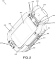
FIG. 2 illustrates a bottom, perspective view of the example portable illumination apparatus ofFIG. 1 . -
FIG. 3 illustrates an exploded view of the example portable illumination apparatus ofFIG. 1 . -
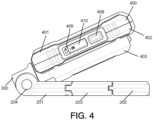
FIG. 4 illustrates a side view of the example portable illumination apparatus ofFIG. 1 in a first orientation. -
FIG. 5 illustrates a side view of the example portable illumination apparatus ofFIG. 1 in a second deployed orientation. -
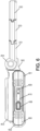
FIG. 6 illustrates a side view of the example portable illumination apparatus ofFIG. 1 in a third deployed orientation. -
FIG. 7 illustrates a side view of the example portable illumination apparatus ofFIG. 1 in a fourth deployed orientation. -
FIG. 8 illustrates a side view of the example portable illumination apparatus ofFIG. 1 in a fifth deployed orientation. -
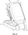
FIG. 9 illustrates a side view of the example portable illumination apparatus ofFIG. 1 in a sixth deployed orientation. - Turning to the figures, in which
FIGS. 1-9 illustrates an exampleportable illumination apparatus 100, in accordance with one or more embodiments. Theportable illumination apparatus 100 may comprise one or more operational elements. Some of the possible operational elements of theportable illumination apparatus 100 are illustrated inFIG. 1 and will now be described. It will be understood that it is not necessary for theportable illumination apparatus 100 to incorporate all the elements illustrated in the figures set forth, and/or described herein. Theportable illumination apparatus 100 may have any combination of the various elements illustrated inFIG. 1 . Moreover, theportable illumination apparatus 100 may have additional operational elements to those illustrated inFIG. 1 . - As illustrated in
FIG. 1 , in accordance with one or more embodiments, the exampleportable illumination apparatus 100 comprises asupport base 200, arotary connector member 300, and alight module 400. - As illustrated in
FIGS. 2 and3 , thesupport base 200 defines aframe member 201 having anopening 202 at a central region thereof. Although the illustrated example embodiments feature theframe member 201 having a generally rectangular cross-section, embodiments are not limited thereto. This disclosure contemplates theframe member 201 having any geometric cross-section that will fall within the spirit and scope of the principles of this disclosure. - The
frame member 201 also includes acarabiner clip member 203 and aconnection region 204 having spaced apartpivot pin members light module 400 about a horizontal axis. Theframe member 201 is composed in whole or in part of a metallic material, a polymer material, and a composite material. Alternatively or additionally, the frame member is composed in whole or in part of a ferromagnetic material. Embodiments, however, are not limited thereto, and thus, this disclosure contemplates theframe member 201 being composed of any suitable material that falls within the spirit and scope of the principles of this disclosure. - In one or more example embodiments, the
carabiner clip member 203 is integrated into theframe member 201 to facilitate secure attachment of theillumination apparatus 100 to an object or surface in a manner that facilitates hands-free use of theillumination apparatus 100. Thecarabiner clip member 203 is pivotably connected to theframe member 201 via a mechanical hinge pin member, and is biased into a closed position via a spring member. - One or more
anti-slip members 209 are arranged on theframe member 201 to form anti-slip zones on a bottom surface of theframe member 201. The one or moreanti-slip members 209 are operable to engage a working surface or support surface. Theanti-slip members 208 are composed of an anti-slip material such as, for example, silicon. Embodiments, however, are not limited thereto, and thus, this disclosure contemplates theanti-slip members 208 being composed of any suitable material that falls within the spirit and scope of the principles of this disclosure. The anti-slip material has a coefficient of friction that inhibits movement of theillumination apparatus 100 on a working surface or support surface by increasing an amount of friction between theillumination apparatus 100 and the working surface or support surface. In this way, theillumination apparatus 100 is anchored or otherwise maintained on the working surface or support surface. - As illustrated in
FIG. 3 , therotary connector member 300 has a bifurcated configuration that comprises anupper bracket member 301 that is operable for connection to alower bracket member 302. Theupper bracket member 301 is also operable for connection to thelight module 400 while thelower bracket member 302 is operable for connection to thesupport base 200. - The
upper bracket member 301 includes anextension member 303 extending therefrom to define a second rotational axis that is perpendicular to the first rotational axis, and which facilitates rotation of thelight module 400 about a vertical axis in a deployed position of thelight module 400. Theextension member 303 includes one or more threads external threads that correspond to internal threads of afastener member 302 to facilitate connection of therotary connector member 300 to thelight module 400. Thelower bracket member 302, viarotary collar members 304, is connected to thepivot pins 207, and in turn, theframe member 201. - The
light module 400 includes alight module housing 401 having a shape or geometric cross-section that corresponds to the shape or geometric cross-section of theframe member 201. Although the illustrated example embodiments feature thelight module housing 401 having a substantially rectangular cross section, embodiments are not limited thereto. This disclosure contemplates thelight module housing 401 having any geometric cross-section that will fall within the spirit and scope of the principles of this disclosure. - The
light module housing 401 is pivotally connected to theframe member 201 at theconnection region 204 via therotary connector member 300 for movement between a stowed position (FIGS. 1 and2 ) and a deployed position (FIGS. 4-9 ) by rotation of thelight module housing 401 about the first rotational axis. In the deployed position, thelight module 400 is rotatable about the second rotational axis. - The
light module housing 401 has a bifurcated configuration of two connected shell members that define an interior space or opening that has alight source region 402 and apower source region 403. Thelight source region 402 may be arranged at an upper section of thelight module 400 and thepower source region 403 may be arranged at a bottom section of thelight module 400. Thelight source region 402 supports one or more light sources 404 operable to illuminate light (provide light illumination). The light sources 404 comprise one or more LEDs 405 to emit illuminating light, and areflector member 412 arranged over the LEDs 405. - As illustrated in
FIG. 3 , the one or more LEDs 405 are arranged in an array on a printed circuit board (PCB) 411. During activation of thelight module 400, heat generated by the LEDs 405 is transmitted to theheat sink 413, which radiates the heat away from thePCB 411. Theheat sink 413 is composed of a thermally conductive material, such as, for example, a metal. Embodiments, however, are not limited thereto, and thus, this disclosure contemplates theheat sink 413 being composed of any suitable material that falls within the spirit and scope of the principles of this disclosure. - In accordance with one or more example embodiments, the color temperature of light emitted by the LEDs 405 is 4,000K. Embodiments, however, are not limited thereto, and thus, this disclosure contemplates the light emitted by the LEDs 405 may have any suitable color temperature that falls within the spirit and scope of the principles of this disclosure.
- A bottom planar surface of the
light source region 402 has an overall surface area that is approximately equal to the overall surface area of an upper planar surface of theframe member 201 so as to directly engage the upper planar surface of theframe member 201 in the stowed position of thelight module 400. - The
power source region 403 supports a rechargeable power source 406 for the one or more light sources 404. The rechargeable power source 406 comprises one or more rechargeable battery cells 407 each having a capacity of at least 2.amp.hours, configured for a total capacity of at least 4.0 amp.hours. In an embodiment, other battery configurations such as pouch cells may be alternatively utilized. The planar surface of thepower source region 403 has an overall surface area that is less than the overall surface area of the upper planar surface of theframe member 201 and the overall area of theopening 202 so as to be recessed in theopening 202 in the stowed position of thelight module 400. Abracket member 414 is provided to maintain the one or more rechargeable batteries 407 in thelight module 400. - A
seal member 416 is provided between the shell members of thelight module housing 401 in order to prevent moisture, debris, particles, etc. from entering into the interior space and adversely affecting the performance of theillumination apparatus 100. - The
light module housing 401 is composed in whole or in part of a metallic material, a polymer material, and a composite material. Alternatively, or additionally, thelight module housing 401 is composed in whole or in part of a ferromagnetic material such as, for example, aluminum. Embodiments, however, are not limited thereto, and thus, this disclosure contemplates thelight module housing 401 being composed of any suitable material that falls within the spirit and scope of the principles of this disclosure. - A magnetic bias is provided to facilitate movement of the
light module 400 from the deployed position to the stowed position and maintain thelight module 400 in the stowed position. In accordance with one or more example embodiments, one or more magnetic elements are integrated in, arranged on, or embedded in the surface of thelight module housing 401. Theframe member 201 includes one or moremagnetic elements 210 to facilitate a magnetic attraction between theframe member 201 and thelight module housing 401 that creates a supplemental torque to magnetically bias thelight module 400 from the deployed position to the stowed position and also magnetically maintain thelight module 400 in the stowed position. - The
light module 400 has apower charging port 408 located on an outer sidewall surface of thelight module housing 401 to facilitate recharging of the rechargeable power source 406. In accordance with one or more example embodiments, thepower charging port 408 comprises a USB-C port that facilitates a wired connection with a male plug of a USB-C charging cable for recharging of the rechargeable power source 406. In accordance with one or more example embodiments, the USB-C port is operable to facilitate a total charging time of 80 minutes to reach a full charged state of the rechargeable power source 406. - The
light module 400 also includes acharge indicator 409 located on an outer sidewall surface of thelight module housing 401 to visual indicate a charge status of the rechargeable power source 406 during a recharging sequence. Thecharge indicator 409 is operable to illuminate a single color that corresponds to charge status of the rechargeable power source 406. Alternatively, thecharge indicator 409 is operable to illuminate a plurality of colors that correspond to charge status of the rechargeable power source 406. - The
light module 400 further also includes acontrol switch member 410 located on an outer sidewall surface of thelight module housing 401 to control activation/deactivation of the light sources 404 between a plurality of operating modes. The one or more LEDs 405 are operable for manual control by a user via thecontrol switch member 410 emit illuminating light. In particular, thecontrol switch member 410 is also operable to control an output/intensity of light emitted by the light sources 404 between the plurality of operating modes. In a first or maximum operating mode, the light sources 404 have an output of 1000 lumens (L) and a runtime of 4 hours. In a second or intermediate operating mode, the light sources 404 have an output of 500lm and a runtime of 8 hours. In a third or minimum operating mode, the light sources 404 have an output of 500lm and a runtime of 12 hours. APCB 415 is provided for thepower charge port 408, thecharge indicator 409, and thepower control switch 410. - The
light module housing 401 may be oriented, in the stowed position, such that an upper planar surface of thelight source region 402 is directed away from theframe member 201. In the stowed position of thelight module 400, the lower planar surface of thelight source region 402 is also coplanar with and directly engages the upper planar surface of theframe member 201. - In the illustrated example of
FIG. 4 , thelight module 400 is in a deployed state in which it is rotated approximately 45° about the first rotational axis. In this orientation of thelight module 400, thepower source region 403 is moved out of theopening 202 and thelight source region 402 is oriented to emit illuminating light in a direction away from theframe member 201. - In the illustrated example of
FIG. 5 , thelight module 400 is in a deployed state in which it is rotated approximately 90° about the first rotational axis A1. In this orientation of thelight module 400, thepower source region 403 is moved out of theopening 202 and thelight source region 402 is oriented to emit illuminating light in a direction away from theframe member 201. - In the illustrated example of
FIG. 6 , thelight module 400 is in a deployed state in which it is rotated approximately 180° about the first rotational axis A1. In this orientation of thelight module 400, thepower source region 403 is moved out of theopening 202 and thelight source region 402 is oriented to emit illuminating light in a direction away from theframe member 201. - In the illustrated example of
FIGS. 7 and8 , thelight module 400 is in a deployed state in which it is rotated approximately 45° about the first rotational axis and also rotated approximately 90° about the second rotational axis. In this orientation of thelight module 400, thepower source region 403 is moved out of theopening 202 and thelight source region 402 is oriented to emit illuminating light in a direction away from theframe member 201. - In the illustrated example of
FIG. 9 , thelight module 400 is in a deployed state in which it is rotated approximately 45° about the first rotational axis and also rotated approximately 180° about the second rotational axis. In this orientation of thelight module 400, thepower source region 403 is moved out of theopening 202 and thelight source region 402 is oriented to emit illuminating light in a direction towards theframe member 201. - Example 1 may include an illumination apparatus, comprising: a support base defining a frame member having an opening at a center thereof, a carabiner clip member, and a connection region defining a first rotational axis; a rotary connector member defining a second rotational axis that is perpendicular to the first rotational axis; and a light module mountable (mounted) to the connection region via the rotary connector member for movement between a stowed position and a deployed position by rotation of the light module about the first rotational axis. The light module includes: a light module housing having a light source region that supports one or more light sources operable to illuminate light (provide light illumination), the light source region having a surface area that is approximately equal to a surface area of the frame member so as to engage a planar surface of the frame member in the stowed position of the light module, and a power source region that supports a rechargeable power source, power source region having a surface area that is less than the surface area of the frame member so as to be recessed in the opening in the stowed position of the light module.
- Example 2 may include the illumination apparatus of Example 1, wherein in the stowed position, the light module is oriented such that a first planar surface of the light source region is directed away from the frame member.
- Example 3 may include the illumination apparatus of Example 1, wherein in the stowed position, the light module is oriented such that a first planar surface of the light source region is coplanar with a first planar surface of the frame member.
- Example 4 may include the illumination apparatus of Example 1, wherein in the stowed position, the light module is oriented such that a planar surface of the light source region engages a first planar surface of the frame member.
- Example 5 may include the illumination apparatus of Example 1, wherein in the deployed position, the light module is rotatable about the second rotational axis.
- Example 6 may include the illumination apparatus of Example 1, wherein the frame member is composed in whole or in part of a metallic material, a polymer material, and a composite material.
- Example 7 may include the illumination apparatus of Example 1, wherein the frame member is composed in whole or in part of a ferromagnetic material.
- Example 8 may include the illumination apparatus of Example 1, further comprising a magnetic bias to facilitate movement of the light module from the deployed position to the stowed position and maintain the light module in the stowed position.
- Example 9 may include the illumination apparatus of Example 8, further comprising one or more first magnetic elements arranged on or embedded in the surface of the light module.
- Example 100 may include the illumination apparatus of Example 9, wherein the frame member comprises a second magnetic element to facilitate a magnetic attraction between the frame member and the light module that creates a supplemental torque that magnetically biases the light module from the deployed position to the stowed position and also magnetically maintains the light module in the stowed position.
- Example 11 may include the illumination apparatus of Example 1, wherein the frame member comprises a pair of spaced apart frame leg members connected by a pair of frame cross members.
- Example 12 may include the illumination apparatus of Example 11, wherein the carabiner clip member is integrated into one of the frame leg members.
- Example 13 may include the illumination apparatus of Example 12, wherein the carabiner clip member is pivotably connected to the frame leg member via a hinge pin member.
- Example 14 may include the illumination apparatus of Example 13, wherein the carabiner clip member is biased into a closed position via a spring member.
- Example 15 may include the illumination apparatus of Example 11, wherein each frame leg member terminates to a pivot pin at the connection region.
- Example 16 may include the illumination apparatus of Example 15, wherein the rotary member is connected at a first longitudinal end to the light module and at a second longitudinal end to the frame member.
- Example 17 may include the illumination apparatus of Example 1, wherein the light module is composed in whole or in part of a metallic material, a polymer material, and a composite material.
- Example 18 may include the illumination apparatus of Example 1, wherein the light module is composed in whole or in part of a ferromagnetic material.
- Example 19 may include the illumination apparatus of Example 1, wherein the light module comprises a power charging port located on an outer sidewall surface thereof to facilitate recharging of the rechargeable power source.
- Example 20 may include the illumination apparatus of Example 19, wherein the power charging port comprises a USB-C port.
- Example 21 may include the illumination apparatus of Example 20, wherein the USB-C port facilitates a wired connection with a male plug of a USB-C charging cable for recharging of the rechargeable power source.
- Example 22 may include the illumination apparatus of Example 20, wherein the USB-C port facilitates a total charging time of 80 minutes to reach a full charged state of the rechargeable power source.
- Example 23 may include the illumination apparatus of Example 1, wherein the light module comprises a charge indicator located on an outer sidewall surface thereof to visual indicate a charge status of the rechargeable power source during a recharging sequence of the rechargeable power source.
- Example 24 may include the illumination apparatus of Example 23, wherein the charge indicator is operable to illuminate a single color that corresponds to charge status of the rechargeable power source.
- Example 25 may include the illumination apparatus of Example 1, wherein the light sources comprise one or more LEDs.
- Example 26 may include the illumination apparatus of Example 25, wherein a color temperature of light emitted by the LEDs is 4,000K.
- Example 27 may include the illumination apparatus of Example 25, wherein the light module comprises a control switch member located on an outer sidewall surface thereof which is operable to control activation/deactivation of the LEDs.
- Example 28 may include the illumination apparatus of Example 27, wherein the control switch member is operable to control an output/intensity of light emitted by the LEDs between a plurality of operating modes.
- Example 29 may include the illumination apparatus of Example 28, wherein in a first/maximum operating mode, the light sources have an output of 1000lmand a runtime of 4 hours.
- Example 30 may include the illumination apparatus of Example 28, wherein in a second/intermediate operating mode, the light sources have an output of 500lmand a runtime of 8 hours.
- Example 31 may include the illumination apparatus of Example 28, wherein in a third/minimum operating mode, the light sources have an output of 500lmand a runtime of 12 hours.
- Example 32 may include the illumination apparatus of Example 1, wherein the rechargeable power source region 404 comprises a rechargeable battery power source.
- Example 33 may include the illumination apparatus of Example 32, wherein the rechargeable battery source comprises one or more rechargeable batteries.
- Example 34 may include the illumination apparatus of Example 1, further comprising one or more anti-slip members on the frame member to facilitate anti-slip zones on the surface of the frame member.
- Example 35 may include the illumination apparatus of Example 34, wherein the one or more anti-slip members are composed of an anti-slip material having a coefficient of friction that inhibits movement of the illumination apparatus on a working surface.
- Example 36 may include the illumination apparatus of Example 35, wherein the anti-slip material comprises silicon.
- Example 1B may include an illumination apparatus, comprising: a support base defining a frame member having an opening at a center thereof and a connection region defining a first rotational axis; a rotary member defining a second rotational axis that is perpendicular to the first rotational axis; and a light module mountable (mounted) on the connection region via the rotary member for movement between a stowed position and a deployed position by rotation of the light module about the first rotational axis, the light module including a light module housing having a light source region operable to illuminate light (provide light illumination), and a power source region operable to supply power to the light source region, the power source region having a surface area that is less than a surface area of the frame base member so as to be recessed in the opening of the frame member in the stowed position of the light module.
- Example 2B may include the illumination apparatus of Example 1B, wherein in the stowed position, the light module is oriented such that a first planar surface of the light source region is directed away from the frame member.
- Example 3B may include the illumination apparatus of Example 1B, wherein in the stowed position, the light module is oriented such that a first planar surface of the light source region is coplanar with a first planar surface of the frame member.
- Example 4B may include the illumination apparatus of Example 1B, wherein in the stowed position, the light module is oriented such that a planar surface of the light source region engages a first planar surface of the frame member.
- Example 5B may include the illumination apparatus of Example 1B, wherein in the deployed position, the light module is rotatable about the second rotational axis.
- Example 6B may include the illumination apparatus of Example 1B, wherein the frame member is composed in whole or in part of a metallic material, a polymer material, and a composite material.
- Example 7B may include the illumination apparatus of Example 1B, wherein the frame member is composed in whole or in part of a ferromagnetic material.
- Example 8B may include the illumination apparatus of Example 1B, further comprising a magnetic bias to facilitate movement of the light module from the deployed position to the stowed position and maintain the light module in the stowed position.
- Example 9B may include the illumination apparatus of Example 8B, further comprising one or more first magnetic elements arranged on or embedded in the surface of the light module.
- Example 10B may include the illumination apparatus of Example 9B, wherein the frame member comprises a second magnetic element to facilitate a magnetic attraction between the frame member and the light module that creates a supplemental torque that magnetically biases the light module from the deployed position to the stowed position and also magnetically maintains the light module in the stowed position.
- Example 11B may include the illumination apparatus of Example 1B, wherein the frame member comprises a pair of spaced apart frame leg members connected by a pair of frame cross members.
- Example 12B may include the illumination apparatus of Example 11B, wherein the carabiner clip member is integrated into one of the frame leg members.
- Example 13B may include the illumination apparatus of Example 12B, wherein the carabiner clip member is pivotably connected to the frame leg member via a hinge pin member.
- Example 14B may include the illumination apparatus of Example 13B, wherein the carabiner clip member is biased into a closed position via a spring member.
- Example 15B may include the illumination apparatus of Example 11B, wherein each frame leg member terminates to a pivot pin at the connection region.
- Example 16B may include the illumination apparatus of Example 15B, wherein the rotary member is connected at a first longitudinal end to the light module and at a second longitudinal end to the frame member.
- Example 17B may include the illumination apparatus of Example 1B, wherein the light module is composed in whole or in part of a metallic material, a polymer material, and a composite material.
- Example 18B may include the illumination apparatus of Example 1B, wherein the light module is composed in whole or in part of a ferromagnetic material.
- Example 19B may include the illumination apparatus of Example 1B, wherein the light module comprises a power charging port located on an outer sidewall surface thereof to facilitate recharging of the rechargeable power source.
- Example 20B may include the illumination apparatus of Example 19B, wherein the power charging port comprises a USB-C port.
- Example 21B may include the illumination apparatus of Example 20B, wherein the USB-C port facilitates a wired connection with a male plug of a USB-C charging cable for recharging of the rechargeable power source.
- Example 22B may include the illumination apparatus of Example 20B, wherein the USB-C port facilitates a total charging time of 80 minutes to reach a full charged state of the rechargeable power source.
- Example 23B may include the illumination apparatus of Example 1B, wherein the light module comprises a charge indicator located on an outer sidewall surface thereof to visual indicate a charge status of the rechargeable power source during a recharging sequence of the rechargeable power source.
- Example 24B may include the illumination apparatus of Example 23B, wherein the charge indicator is operable to illuminate a single color that corresponds to charge status of the rechargeable power source.
- Example 25B may include the illumination apparatus of Example 1B, wherein the light sources comprise one or more LEDs.
- Example 26B may include the illumination apparatus of Example 25B, wherein a color temperature of light emitted by the LEDs is 4,000K.
- Example 27B may include the illumination apparatus of Example 25B, wherein the light module comprises a control switch member located on an outer sidewall surface thereof which is operable to control activation/deactivation of the LEDs.
- Example 28B may include the illumination apparatus of Example 27B, wherein the control switch member is operable to control an output/intensity of light emitted by the LEDs between a plurality of operating modes.
- Example 29B may include the illumination apparatus of Example 28B, wherein in a first/maximum operating mode, the light sources have an output of 1000lmand a runtime of 4 hours.
- Example 30B may include the illumination apparatus of Example 28B, wherein in a second/intermediate operating mode, the light sources have an output of 500lmand a runtime of 8 hours.
- Example 31B may include the illumination apparatus of Example 28B, wherein in a third/minimum operating mode, the light sources have an output of 500lmand a runtime of 12 hours.
- Example 32B may include the illumination apparatus of Example 1B, wherein the rechargeable power source region 404 comprises a rechargeable battery power source.
- Example 33B may include the illumination apparatus of Example 32B, wherein the rechargeable battery source comprises one or more rechargeable batteries.
- Example 34B may include the illumination apparatus of Example 1B, further comprising one or more anti-slip members on the frame member to facilitate anti-slip zones on the surface of the frame member.
- Example 35B may include the illumination apparatus of Example 34B, wherein the one or more anti-slip members are composed of an anti-slip material having a coefficient of friction that inhibits movement of the illumination apparatus on a working surface.
- Example 36B may include the illumination apparatus of Example 35B, wherein the anti-slip material comprises silicon.
- Example 1C may include an illumination apparatus, comprising: a support base defining a frame member having a connection region defining a first rotational axis; a rotary member, attached to the frame member at the connection region, and defining a second rotational axis that is perpendicular to the first rotational axis; and a light module having one or more light sources operable to illuminate light (provide light illumination), the light module being mountable (mounted) on the connection region via the rotary member for movement between a stowed position and a deployed position by rotation of the light module about the first rotational axis, wherein the light module is rotatable about the second rotational axis when placed in the deployed position.
- Example 2C may include the illumination apparatus of Example 1C, wherein in the stowed position, the light module is oriented such that a first planar surface of the light source region is directed away from the frame member.
- Example 3C may include the illumination apparatus of Example 1C, wherein in the stowed position, the light module is oriented such that a first planar surface of the light source region is coplanar with a first planar surface of the frame member.
- Example 4C may include the illumination apparatus of Example 1C, wherein in the stowed position, the light module is oriented such that a planar surface of the light source region engages a first planar surface of the frame member.
- Example 5C may include the illumination apparatus of Example 1C, wherein in the deployed position, the light module is rotatable about the second rotational axis.
- Example 6C may include the illumination apparatus of Example 1C, wherein the frame member is composed in whole or in part of a metallic material, a polymer material, and a composite material.
- Example 7C may include the illumination apparatus of Example 1C, wherein the frame member is composed in whole or in part of a ferromagnetic material.
- Example 8C may include the illumination apparatus of Example 1C, further comprising a magnetic bias to facilitate movement of the light module from the deployed position to the stowed position and maintain the light module in the stowed position.
- Example 9C may include the illumination apparatus of Example 8C, further comprising one or more first magnetic elements arranged on or embedded in the surface of the light module.
- Example 10C may include the illumination apparatus of Example 9C, wherein the frame member comprises a second magnetic element to facilitate a magnetic attraction between the frame member and the light module that creates a supplemental torque that magnetically biases the light module from the deployed position to the stowed position and also magnetically maintains the light module in the stowed position.
- Example 11C may include the illumination apparatus of Example 1C, wherein the frame member comprises a pair of spaced apart frame leg members connected by a pair of frame cross members.
- Example 12C may include the illumination apparatus of Example 11C, wherein the carabiner clip member is integrated into one of the frame leg members.
- Example 13C may include the illumination apparatus of Example 12C, wherein the carabiner clip member is pivotably connected to the frame leg member via a hinge pin member.
- Example 14C may include the illumination apparatus of Example 13C, wherein the carabiner clip member is biased into a closed position via a spring member.
- Example 15C may include the illumination apparatus of Example 11C, wherein each frame leg member terminates to a pivot pin at the connection region.
- Example 16C may include the illumination apparatus of Example 15C, wherein the rotary member is connected at a first longitudinal end to the light module and at a second longitudinal end to the frame member.
- Example 17C may include the illumination apparatus of Example 1C, wherein the light module is composed in whole or in part of a metallic material, a polymer material, and a composite material.
- Example 18C may include the illumination apparatus of Example 1C, wherein the light module is composed in whole or in part of a ferromagnetic material.
- Example 19C may include the illumination apparatus of Example 1C, wherein the light module comprises a power charging port located on an outer sidewall surface thereof to facilitate recharging of the rechargeable power source.
- Example 20C may include the illumination apparatus of Example 19C, wherein the power charging port comprises a USB-C port.
- Example 21C may include the illumination apparatus of Example 20C, wherein the USB-C port facilitates a wired connection with a male plug of a USB-C charging cable for recharging of the rechargeable power source.
- Example 22C may include the illumination apparatus of Example 20C, wherein the USB-C port facilitates a total charging time of 80 minutes to reach a full charged state of the rechargeable power source.
- Example 23C may include the illumination apparatus of Example 1C, wherein the light module comprises a charge indicator located on an outer sidewall surface thereof to visual indicate a charge status of the rechargeable power source during a recharging sequence of the rechargeable power source.
- Example 24C may include the illumination apparatus of Example 23C, wherein the charge indicator is operable to illuminate a single color that corresponds to charge status of the rechargeable power source.
- Example 25C may include the illumination apparatus of Example 1C, wherein the light sources comprise one or more LEDs.
- Example 26C may include the illumination apparatus of Example 25C, wherein a color temperature of light emitted by the LEDs is 4,000K.
- Example 27C may include the illumination apparatus of Example 25C, wherein the light module comprises a control switch member located on an outer sidewall surface thereof which is operable to control activation/deactivation of the LEDs.
- Example 28C may include the illumination apparatus of Example 27C, wherein the control switch member is operable to control an output/intensity of light emitted by the LEDs between a plurality of operating modes.
- Example 29C may include the illumination apparatus of Example 28C, wherein in a first/maximum operating mode, the light sources have an output of 1000lmand a runtime of 4 hours.
- Example 30C may include the illumination apparatus of Example 28C, wherein in a second/intermediate operating mode, the light sources have an output of 500lmand a runtime of 8 hours.
- Example 31C may include the illumination apparatus of Example 28C, wherein in a third/minimum operating mode, the light sources have an output of 500lmand a runtime of 12 hours.
- Example 32C may include the illumination apparatus of Example 1C, wherein the rechargeable power source region 404 comprises a rechargeable battery power source.
- Example 33C may include the illumination apparatus of Example 32C, wherein the rechargeable battery source comprises one or more rechargeable batteries.
- Example 34C may include the illumination apparatus of Example 1C, further comprising one or more anti-slip members on the frame member to facilitate anti-slip zones on the surface of the frame member.
- Example 35C may include the illumination apparatus of Example 34C, wherein the one or more anti-slip members are composed of an anti-slip material having a coefficient of friction that inhibits movement of the illumination apparatus on a working surface.
- Example 36C may include the illumination apparatus of Example 35C, wherein the anti-slip material comprises silicon.
-
ITEM PERFORMANCE CHARACTERISTICS Power source 18650 Cells 4V 4.0Ah (2*2.0Ah) Brightness • High: 1000 lm(Min High -700 lm) • Medium: 500 lm (Min Med -350 lm) • Low: 250 lm (Min Low-150 lm) Runtime • High: 4 hours (Min High-2 hrs) • Medium: 8 hours (Min Med-4.5 hrs) • Low: 12 hours Charge time 80min= 100% (Min. -100min) Weight < 0.34 kg (0.75 lbs)
Claims (15)
- A portable illumination apparatus, comprising:a support base defining a frame member having an opening substantially at a center thereof and a connection region defining a first rotational axis;a rotary member defining a second rotational axis that is perpendicular to the first rotational axis; anda light module mounted on the connection region via the rotary member for movement between a stowed position and a deployed position by rotation of the light module about the first rotational axis, the light module including a light module housing having a light source region that supports one or more light sources operable to provide light illumination, and a power source region operable to supply power to the light source region, the power source region having a surface area that is less than a surface area of the frame base member so as to be recessed in the opening of the frame member in the stowed position of the light module.
- The illumination apparatus of claim 1, wherein in the stowed position, the light module is oriented such that a first planar surface of the light source region is directed away from the frame member.
- The illumination apparatus of claim 1 or claim 2, wherein in the stowed position, the light module is oriented such that a first planar surface of the light source region is coplanar with a first planar surface of the frame member.
- The illumination apparatus of any preceding claim, wherein in the stowed position, the light module is oriented such that a planar surface of the light source region engages a first planar surface of the frame member.
- The illumination apparatus of any preceding claim, wherein in the deployed position, the light module is rotatable about the second rotational axis.
- The illumination apparatus of any preceding claim, wherein the light source region has a surface area that is approximately equal to a surface area of the frame member, so as to engage a planar surface of the frame member in the stowed position of the light module.
- The illumination apparatus of any preceding claim, wherein the light module comprises a power charging port located on an outer sidewall surface thereof to facilitate recharging of the rechargeable power source.
- The illumination apparatus of any preceding claim, wherein the frame member comprises a pair of spaced apart frame leg members connected by a pair of frame cross members.
- The illumination apparatus of claim 8, wherein each frame leg member terminates to a pivot pin at the connection region.
- The illumination apparatus of any preceding claim, wherein the rotary member is connected at a first longitudinal end thereof to the light module and at a second longitudinal end thereof to the frame member.
- The illumination apparatus of any preceding claim, further comprising one or more anti-slip members on the frame member to provide anti-slip zones on the surface of the frame member.
- The illumination apparatus of any preceding claim, wherein the frame member is composed in whole or in part of a ferromagnetic material.
- The illumination apparatus of any preceding claim, wherein the light module is composed in whole or in part of a metallic material, a ferromagnetic material, a polymer material, and a composite material.
- The illumination apparatus of any preceding claim, wherein the rotary member comprises a rotary connector member.
- The illumination apparatus of any preceding claim, wherein the frame member includes a carabiner clip member.
Applications Claiming Priority (1)
| Application Number | Priority Date | Filing Date | Title |
|---|---|---|---|
| US202263345281P | 2022-05-24 | 2022-05-24 |
Publications (1)
| Publication Number | Publication Date |
|---|---|
| EP4283184A1 true EP4283184A1 (en) | 2023-11-29 |
Family
ID=86497721
Family Applications (1)
| Application Number | Title | Priority Date | Filing Date |
|---|---|---|---|
| EP23174503.5A Pending EP4283184A1 (en) | 2022-05-24 | 2023-05-22 | Portable illumination apparatus |
Country Status (2)
| Country | Link |
|---|---|
| US (2) | US12196380B2 (en) |
| EP (1) | EP4283184A1 (en) |
Cited By (1)
| Publication number | Priority date | Publication date | Assignee | Title |
|---|---|---|---|---|
| US12584615B2 (en) | 2019-03-18 | 2026-03-24 | Black & Decker Inc. | Battery powered light |
Families Citing this family (5)
| Publication number | Priority date | Publication date | Assignee | Title |
|---|---|---|---|---|
| USD1044075S1 (en) * | 2022-04-26 | 2024-09-24 | Shenzhen Chuangchaoxin Digital Technology Co., Ltd. | Multifunctional LED book clip light |
| USD1027247S1 (en) * | 2023-04-26 | 2024-05-14 | Zhengzhou Dewenwils Network Technology Co., Ltd. | Book light |
| USD1032904S1 (en) * | 2023-10-23 | 2024-06-25 | Hong Jiang | Book light |
| US20250137619A1 (en) * | 2023-10-31 | 2025-05-01 | Milwaukee Electric Tool Corporation | Task light |
| US20260126155A1 (en) * | 2024-11-06 | 2026-05-07 | Techtronic Cordless Gp | Work light |
Citations (3)
| Publication number | Priority date | Publication date | Assignee | Title |
|---|---|---|---|---|
| WO2016026281A1 (en) * | 2014-08-19 | 2016-02-25 | 上海齐迈五金有限公司 | Multifunctional magnetic disc with lamp |
| US20160265754A1 (en) * | 2015-03-11 | 2016-09-15 | Shanghai Easy-Use Tools Enterprise Co., Ltd. | Work Lamp With Magnetic Tray and Tools |
| EP3691231A1 (en) * | 2019-02-01 | 2020-08-05 | Panasonic Intellectual Property Management Co., Ltd. | Function module |
Family Cites Families (73)
| Publication number | Priority date | Publication date | Assignee | Title |
|---|---|---|---|---|
| US5988828A (en) | 1997-07-18 | 1999-11-23 | Milwaukee Electric Tool Corporation | Portable light incorporating a multi-position hook |
| USD474095S1 (en) | 2002-05-03 | 2003-05-06 | L. Hans Luquire | Combination snap hook and knife |
| USD475591S1 (en) | 2002-05-03 | 2003-06-10 | L. Hans Luquire | Snap hook bottle opener |
| US7126484B1 (en) | 2002-05-03 | 2006-10-24 | Luquire L Hanson | Snap-hook assemblies with added components |
| US7621652B2 (en) | 2005-03-31 | 2009-11-24 | Milwaukee Electric Tool Corporation | Electrical component, such as a lighting unit and battery charger assembly |
| US7390110B2 (en) * | 2005-06-09 | 2008-06-24 | Canlyte, Inc. | Article support device |
| CA2577655C (en) | 2006-02-14 | 2011-04-05 | Angstrom Power Incorporated | Fuel cell devices and method therefor |
| USD574692S1 (en) | 2006-08-09 | 2008-08-12 | Cooper Martin R | Multifunctional clip device |
| US7591572B1 (en) | 2007-04-11 | 2009-09-22 | Levine Jonathan E | Compact lighting device |
| USD565215S1 (en) | 2007-09-25 | 2008-03-25 | Wen-Sung Lee | Flashlight |
| USD592339S1 (en) | 2008-01-25 | 2009-05-12 | Eveready Battery Co., Inc. | Lighting device |
| WO2010008855A1 (en) | 2008-06-23 | 2010-01-21 | Milwaukee Electric Tool Corporation | Electrical component including a battery charger assembly |
| CN201787354U (en) | 2010-07-14 | 2011-04-06 | 上海良相智能化工程有限公司 | Strong light flashlight with video and audio recording function |
| CN201954278U (en) | 2011-02-22 | 2011-08-31 | 邓志强 | Flashlight with USB (universal serial bus) power supply |
| US8348483B2 (en) | 2011-05-06 | 2013-01-08 | Hang-John Lin | Portable illumination device |
| US8905572B2 (en) | 2012-03-28 | 2014-12-09 | Milwaukee Electric Tool Corporation | Portable light, such as a stick light |
| US20130343042A1 (en) | 2012-06-21 | 2013-12-26 | Coast Cutlery Company | Rechargeable flashlight |
| US8888311B2 (en) | 2012-07-31 | 2014-11-18 | Armament Systems And Procedures, Inc. | Flashlight with USB charger |
| CN202901861U (en) | 2012-11-02 | 2013-04-24 | 宁波沃尔斯国际贸易有限公司 | Climbing carabiner type flashlight |
| US8919988B2 (en) | 2013-03-13 | 2014-12-30 | Fiskars Brands, Inc. | Flashlight including battery type indicator |
| DE102013205416A1 (en) | 2013-03-27 | 2014-10-16 | Robert Bosch Gmbh | Battery powered light unit |
| CN203336244U (en) | 2013-06-14 | 2013-12-11 | 赵长义 | Multifunctional field operation glare flashlight |
| US9541244B1 (en) | 2013-12-06 | 2017-01-10 | Cooper Technologies Company | Multi-purpose portable light |
| USD810335S1 (en) | 2014-09-17 | 2018-02-13 | Navajo Manufacturing Company, Inc. | Flashlight |
| USD750825S1 (en) | 2014-09-30 | 2016-03-01 | Cooper Technologies Company | Portable light with headlight and floodlight |
| CN104879656A (en) | 2015-05-11 | 2015-09-02 | 李长润 | Multifunctional portable flashlight with integrated laser spot-lightening and mosquito-repelling functions |
| CN204805960U (en) | 2015-05-29 | 2015-11-25 | 王国萍 | Multi -function flashlight |
| US10001252B2 (en) * | 2015-06-04 | 2018-06-19 | Mathew Inskeep | Expanding multi-faced work light flashlight |
| US10393326B2 (en) * | 2015-06-04 | 2019-08-27 | Vector Products, Inc. | Expanding multi-faced work light flashlight |
| CN106678701A (en) | 2015-11-09 | 2017-05-17 | 南京德朔实业有限公司 | Illuminating device |
| US10323831B2 (en) | 2015-11-13 | 2019-06-18 | Milwaukee Electric Tool Corporation | Utility mount light |
| CN105909999A (en) | 2016-06-03 | 2016-08-31 | 任振宇 | Multifunctional flashlight |
| CN205807024U (en) | 2016-07-17 | 2016-12-14 | 漳州妹族工业设计有限公司 | A kind of multifunctional electric torch containing laser lamp |
| JP6876950B2 (en) * | 2016-08-30 | 2021-05-26 | パナソニックIpマネジメント株式会社 | lighting equipment |
| CN206268860U (en) | 2016-12-08 | 2017-06-20 | 上海齐迈五金有限公司 | A kind of Convenient lamp with Fastener for climbing mountain |
| CN206890148U (en) | 2017-03-09 | 2018-01-16 | 广州舜亚电子有限公司 | A kind of multifunction laser torch |
| CN206608780U (en) | 2017-03-09 | 2017-11-03 | 广州舜亚电子有限公司 | A kind of laser torch |
| CN206904813U (en) | 2017-07-14 | 2018-01-19 | 杭州途高电器有限公司 | LED worklight |
| US10458641B2 (en) | 2017-09-22 | 2019-10-29 | Milwaukee Electric Tool Corporation | Hot stick light |
| US10984166B2 (en) | 2017-09-29 | 2021-04-20 | Oracle International Corporation | System and method for extracting website characteristics |
| CN207162185U (en) | 2017-10-10 | 2018-03-30 | 温州乐邦光电科技有限公司 | A kind of flashlight with laser irradiation |
| CN107990172A (en) | 2017-11-21 | 2018-05-04 | 泰州克罗米德机械设备有限公司 | Portable multifunction electric torch |
| US10180221B1 (en) * | 2018-02-12 | 2019-01-15 | Mpowerd Inc. | Modular solar-powered lighting devices and components thereof |
| WO2019183058A1 (en) | 2018-03-19 | 2019-09-26 | Milwaukee Electric Tool Corporation | Folding flood lighting device |
| US11098858B2 (en) | 2018-04-26 | 2021-08-24 | Milwaukee Electric Tool Corporation | Portable light having a pivotable light head |
| US11035556B2 (en) | 2018-04-27 | 2021-06-15 | Milwaukee Electric Tool Corporation | Portable lighting device |
| USD874043S1 (en) | 2018-05-07 | 2020-01-28 | Wen-Sung Lee | Flashlight |
| USD875285S1 (en) | 2018-08-21 | 2020-02-11 | Alliance Sports Group, L.P. | Lighting device |
| USD870941S1 (en) | 2018-09-14 | 2019-12-24 | Shawshank Ledz Inc. | COB LED flashlight |
| US11160329B2 (en) | 2018-09-19 | 2021-11-02 | Milwaukee Electric Tool Corporation | Clip for hard hat |
| US11703212B2 (en) * | 2018-10-08 | 2023-07-18 | Walter R. fucker Enterprises, Ltd. | Portable light |
| USD882838S1 (en) | 2018-10-22 | 2020-04-28 | Ningbo Sunree Outdoor Products Co., Ltd. | Handheld work light |
| USD878648S1 (en) | 2018-10-23 | 2020-03-17 | Yan Zhao | Emergency light |
| US11019870B2 (en) | 2018-11-21 | 2021-06-01 | Milwaukee Electric Tool Corporation | Hard hat lamp attachment system |
| WO2020106878A1 (en) | 2018-11-21 | 2020-05-28 | Milwaukee Electric Tool Corporation | Hard hat lamp attachment system |
| CN111256054B (en) | 2018-11-30 | 2023-11-07 | 米沃奇电动工具公司 | portable lighting device |
| USD890396S1 (en) | 2018-12-22 | 2020-07-14 | Ideapond Llc | Utility light |
| EP3903021A4 (en) | 2019-02-01 | 2022-12-21 | Milwaukee Electric Tool Corporation | HIGH VISIBILITY HEADLAMP |
| JP6952265B2 (en) | 2019-02-01 | 2021-10-20 | パナソニックIpマネジメント株式会社 | Functional module |
| US11255525B2 (en) | 2019-03-18 | 2022-02-22 | Black & Decker Inc. | Battery powered light |
| CN209725895U (en) | 2019-03-29 | 2019-12-03 | 宁波攀峰警用装备科技有限公司 | A kind of police Multi-function lighting device |
| US11125421B2 (en) * | 2019-03-29 | 2021-09-21 | Walter R. Tucker Enterprises, Ltd. | Clamping work light |
| US10578297B1 (en) | 2019-06-20 | 2020-03-03 | Smartech, Inc. | Multi-function flashlight |
| US10663150B1 (en) * | 2019-06-25 | 2020-05-26 | Phillip Luna | Hands-free forearm flashlight having a base with hinge and light panel coupled to hinge with strap coupled to the base |
| US10962180B2 (en) | 2019-08-01 | 2021-03-30 | Walter R. Tucker Enterprises, Ltd. | Handheld clamp work light |
| WO2021081077A1 (en) | 2019-10-21 | 2021-04-29 | Milwaukee Electric Tool Corporation | Portable lighting device with ramp-down capability |
| WO2021097056A1 (en) | 2019-11-14 | 2021-05-20 | Milwaukee Electric Tool Corporation | Hard hat attachment system and safety equipment |
| AU2020382601A1 (en) | 2019-11-14 | 2022-05-26 | Milwaukee Electric Tool Corporation | Hard hat attachment system and safety equipment |
| CN212617986U (en) | 2019-11-22 | 2021-02-26 | 米沃奇电动工具公司 | working lamp |
| US11493192B2 (en) | 2019-12-05 | 2022-11-08 | LB Marketing, Inc. | Lighting system with detachable flashlight head |
| US11156330B2 (en) | 2019-12-05 | 2021-10-26 | Premier Products Inc. | Portable lighting device with an illuminated indicia |
| US11402085B2 (en) | 2020-01-13 | 2022-08-02 | Promier Products Inc. | Portable lighting device with multiple mounting features and configurations |
| US11913612B2 (en) * | 2021-02-24 | 2024-02-27 | Nanjing Chervon Industry Co., Ltd. | Lighting device |
-
2023
- 2023-05-08 US US18/313,909 patent/US12196380B2/en active Active
- 2023-05-22 EP EP23174503.5A patent/EP4283184A1/en active Pending
-
2024
- 2024-12-05 US US18/969,993 patent/US20250093000A1/en active Pending
Patent Citations (3)
| Publication number | Priority date | Publication date | Assignee | Title |
|---|---|---|---|---|
| WO2016026281A1 (en) * | 2014-08-19 | 2016-02-25 | 上海齐迈五金有限公司 | Multifunctional magnetic disc with lamp |
| US20160265754A1 (en) * | 2015-03-11 | 2016-09-15 | Shanghai Easy-Use Tools Enterprise Co., Ltd. | Work Lamp With Magnetic Tray and Tools |
| EP3691231A1 (en) * | 2019-02-01 | 2020-08-05 | Panasonic Intellectual Property Management Co., Ltd. | Function module |
Cited By (1)
| Publication number | Priority date | Publication date | Assignee | Title |
|---|---|---|---|---|
| US12584615B2 (en) | 2019-03-18 | 2026-03-24 | Black & Decker Inc. | Battery powered light |
Also Published As
| Publication number | Publication date |
|---|---|
| US20250093000A1 (en) | 2025-03-20 |
| US20230392760A1 (en) | 2023-12-07 |
| US12196380B2 (en) | 2025-01-14 |
Similar Documents
| Publication | Publication Date | Title |
|---|---|---|
| US12196380B2 (en) | Portable illumination apparatus | |
| EP4283185A1 (en) | Portable flashlight | |
| US10782007B2 (en) | Modular system | |
| US9057490B2 (en) | Portable light having a movable head and a USB charging port | |
| US7926967B2 (en) | Headlight devices and methods | |
| US20210310641A1 (en) | Modular System | |
| US7172310B2 (en) | Flashlight with pivotal swivel light emitting assembly | |
| JP6890309B2 (en) | Functional module | |
| JP5379278B2 (en) | lamp | |
| CN101093060B (en) | Led-based lamp equipped with a compact case and with multidirectional orientation | |
| US12228255B2 (en) | Lighting device | |
| US20180283624A1 (en) | Multi-functional bluetooth lighting devices | |
| US20250137619A1 (en) | Task light | |
| US20230137703A1 (en) | Detachable lantern lighting device | |
| US20250003559A1 (en) | Portable area light | |
| US20180224102A1 (en) | Methods and apparatus for a multi-functional foldable thin light | |
| US20200049332A1 (en) | Modular system | |
| US20180128461A1 (en) | Multi-bodied flashlight | |
| US12435845B2 (en) | Headlamp assembly with selectable power source | |
| ES1265921Y1 (en) | EMERGENCY LIGHT FOR VEHICLES WITH DUAL FUNCTIONALITY | |
| US20050259420A1 (en) | Storage container lighting system | |
| CN219674034U (en) | Outdoor lamp and outdoor lamp | |
| US20260002645A1 (en) | Portable lighting device with a flexible and deployable led lighting element | |
| US8659228B2 (en) | LED ballast mount | |
| JP2003217765A (en) | lighting equipment |
Legal Events
| Date | Code | Title | Description |
|---|---|---|---|
| PUAI | Public reference made under article 153(3) epc to a published international application that has entered the european phase |
Free format text: ORIGINAL CODE: 0009012 |
|
| STAA | Information on the status of an ep patent application or granted ep patent |
Free format text: STATUS: THE APPLICATION HAS BEEN PUBLISHED |
|
| AK | Designated contracting states |
Kind code of ref document: A1 Designated state(s): AL AT BE BG CH CY CZ DE DK EE ES FI FR GB GR HR HU IE IS IT LI LT LU LV MC ME MK MT NL NO PL PT RO RS SE SI SK SM TR |
|
| STAA | Information on the status of an ep patent application or granted ep patent |
Free format text: STATUS: REQUEST FOR EXAMINATION WAS MADE |
|
| 17P | Request for examination filed |
Effective date: 20240528 |
|
| RBV | Designated contracting states (corrected) |
Designated state(s): AL AT BE BG CH CY CZ DE DK EE ES FI FR GB GR HR HU IE IS IT LI LT LU LV MC ME MK MT NL NO PL PT RO RS SE SI SK SM TR |
|
| STAA | Information on the status of an ep patent application or granted ep patent |
Free format text: STATUS: EXAMINATION IS IN PROGRESS |
|
| 17Q | First examination report despatched |
Effective date: 20260102 |