EP4283171A1 - Air-conditioning device - Google Patents
Air-conditioning device Download PDFInfo
- Publication number
- EP4283171A1 EP4283171A1 EP21920938.4A EP21920938A EP4283171A1 EP 4283171 A1 EP4283171 A1 EP 4283171A1 EP 21920938 A EP21920938 A EP 21920938A EP 4283171 A1 EP4283171 A1 EP 4283171A1
- Authority
- EP
- European Patent Office
- Prior art keywords
- heat exchanger
- port
- flow switching
- switching valve
- pressure
- Prior art date
- Legal status (The legal status is an assumption and is not a legal conclusion. Google has not performed a legal analysis and makes no representation as to the accuracy of the status listed.)
- Withdrawn
Links
Images





Classifications
-
- F—MECHANICAL ENGINEERING; LIGHTING; HEATING; WEAPONS; BLASTING
- F24—HEATING; RANGES; VENTILATING
- F24F—AIR-CONDITIONING; AIR-HUMIDIFICATION; VENTILATION; USE OF AIR CURRENTS FOR SCREENING
- F24F11/00—Control or safety arrangements
- F24F11/30—Control or safety arrangements for purposes related to the operation of the system, e.g. for safety or monitoring
- F24F11/41—Defrosting; Preventing freezing
- F24F11/42—Defrosting; Preventing freezing of outdoor units
-
- F—MECHANICAL ENGINEERING; LIGHTING; HEATING; WEAPONS; BLASTING
- F24—HEATING; RANGES; VENTILATING
- F24F—AIR-CONDITIONING; AIR-HUMIDIFICATION; VENTILATION; USE OF AIR CURRENTS FOR SCREENING
- F24F11/00—Control or safety arrangements
- F24F11/70—Control systems characterised by their outputs; Constructional details thereof
- F24F11/80—Control systems characterised by their outputs; Constructional details thereof for controlling the temperature of the supplied air
- F24F11/83—Control systems characterised by their outputs; Constructional details thereof for controlling the temperature of the supplied air by controlling the supply of heat-exchange fluids to heat-exchangers
- F24F11/84—Control systems characterised by their outputs; Constructional details thereof for controlling the temperature of the supplied air by controlling the supply of heat-exchange fluids to heat-exchangers using valves
-
- F—MECHANICAL ENGINEERING; LIGHTING; HEATING; WEAPONS; BLASTING
- F25—REFRIGERATION OR COOLING; COMBINED HEATING AND REFRIGERATION SYSTEMS; HEAT PUMP SYSTEMS; MANUFACTURE OR STORAGE OF ICE; LIQUEFACTION SOLIDIFICATION OF GASES
- F25B—REFRIGERATION MACHINES, PLANTS OR SYSTEMS; COMBINED HEATING AND REFRIGERATION SYSTEMS; HEAT PUMP SYSTEMS
- F25B13/00—Compression machines, plants or systems, with reversible cycle
-
- F—MECHANICAL ENGINEERING; LIGHTING; HEATING; WEAPONS; BLASTING
- F25—REFRIGERATION OR COOLING; COMBINED HEATING AND REFRIGERATION SYSTEMS; HEAT PUMP SYSTEMS; MANUFACTURE OR STORAGE OF ICE; LIQUEFACTION SOLIDIFICATION OF GASES
- F25B—REFRIGERATION MACHINES, PLANTS OR SYSTEMS; COMBINED HEATING AND REFRIGERATION SYSTEMS; HEAT PUMP SYSTEMS
- F25B41/00—Fluid-circulation arrangements
- F25B41/20—Disposition of valves, e.g. of on-off valves or flow control valves
-
- F—MECHANICAL ENGINEERING; LIGHTING; HEATING; WEAPONS; BLASTING
- F25—REFRIGERATION OR COOLING; COMBINED HEATING AND REFRIGERATION SYSTEMS; HEAT PUMP SYSTEMS; MANUFACTURE OR STORAGE OF ICE; LIQUEFACTION SOLIDIFICATION OF GASES
- F25B—REFRIGERATION MACHINES, PLANTS OR SYSTEMS; COMBINED HEATING AND REFRIGERATION SYSTEMS; HEAT PUMP SYSTEMS
- F25B41/00—Fluid-circulation arrangements
- F25B41/20—Disposition of valves, e.g. of on-off valves or flow control valves
- F25B41/26—Disposition of valves, e.g. of on-off valves or flow control valves of fluid flow reversing valves
-
- F—MECHANICAL ENGINEERING; LIGHTING; HEATING; WEAPONS; BLASTING
- F25—REFRIGERATION OR COOLING; COMBINED HEATING AND REFRIGERATION SYSTEMS; HEAT PUMP SYSTEMS; MANUFACTURE OR STORAGE OF ICE; LIQUEFACTION SOLIDIFICATION OF GASES
- F25B—REFRIGERATION MACHINES, PLANTS OR SYSTEMS; COMBINED HEATING AND REFRIGERATION SYSTEMS; HEAT PUMP SYSTEMS
- F25B47/00—Arrangements for preventing or removing deposits or corrosion, not provided for in another subclass
- F25B47/02—Defrosting cycles
-
- F—MECHANICAL ENGINEERING; LIGHTING; HEATING; WEAPONS; BLASTING
- F25—REFRIGERATION OR COOLING; COMBINED HEATING AND REFRIGERATION SYSTEMS; HEAT PUMP SYSTEMS; MANUFACTURE OR STORAGE OF ICE; LIQUEFACTION SOLIDIFICATION OF GASES
- F25B—REFRIGERATION MACHINES, PLANTS OR SYSTEMS; COMBINED HEATING AND REFRIGERATION SYSTEMS; HEAT PUMP SYSTEMS
- F25B47/00—Arrangements for preventing or removing deposits or corrosion, not provided for in another subclass
- F25B47/02—Defrosting cycles
- F25B47/022—Defrosting cycles hot gas defrosting
- F25B47/025—Defrosting cycles hot gas defrosting by reversing the cycle
-
- F—MECHANICAL ENGINEERING; LIGHTING; HEATING; WEAPONS; BLASTING
- F25—REFRIGERATION OR COOLING; COMBINED HEATING AND REFRIGERATION SYSTEMS; HEAT PUMP SYSTEMS; MANUFACTURE OR STORAGE OF ICE; LIQUEFACTION SOLIDIFICATION OF GASES
- F25B—REFRIGERATION MACHINES, PLANTS OR SYSTEMS; COMBINED HEATING AND REFRIGERATION SYSTEMS; HEAT PUMP SYSTEMS
- F25B5/00—Compression machines, plants or systems, with several evaporator circuits, e.g. for varying refrigerating capacity
- F25B5/02—Compression machines, plants or systems, with several evaporator circuits, e.g. for varying refrigerating capacity arranged in parallel
-
- F—MECHANICAL ENGINEERING; LIGHTING; HEATING; WEAPONS; BLASTING
- F25—REFRIGERATION OR COOLING; COMBINED HEATING AND REFRIGERATION SYSTEMS; HEAT PUMP SYSTEMS; MANUFACTURE OR STORAGE OF ICE; LIQUEFACTION SOLIDIFICATION OF GASES
- F25B—REFRIGERATION MACHINES, PLANTS OR SYSTEMS; COMBINED HEATING AND REFRIGERATION SYSTEMS; HEAT PUMP SYSTEMS
- F25B6/00—Compression machines, plants or systems, with several condenser circuits
- F25B6/02—Compression machines, plants or systems, with several condenser circuits arranged in parallel
-
- F—MECHANICAL ENGINEERING; LIGHTING; HEATING; WEAPONS; BLASTING
- F25—REFRIGERATION OR COOLING; COMBINED HEATING AND REFRIGERATION SYSTEMS; HEAT PUMP SYSTEMS; MANUFACTURE OR STORAGE OF ICE; LIQUEFACTION SOLIDIFICATION OF GASES
- F25B—REFRIGERATION MACHINES, PLANTS OR SYSTEMS; COMBINED HEATING AND REFRIGERATION SYSTEMS; HEAT PUMP SYSTEMS
- F25B2313/00—Compression machines, plants or systems with reversible cycle not otherwise provided for
- F25B2313/025—Compression machines, plants or systems with reversible cycle not otherwise provided for using multiple outdoor units
- F25B2313/0251—Compression machines, plants or systems with reversible cycle not otherwise provided for using multiple outdoor units being defrosted alternately
-
- F—MECHANICAL ENGINEERING; LIGHTING; HEATING; WEAPONS; BLASTING
- F25—REFRIGERATION OR COOLING; COMBINED HEATING AND REFRIGERATION SYSTEMS; HEAT PUMP SYSTEMS; MANUFACTURE OR STORAGE OF ICE; LIQUEFACTION SOLIDIFICATION OF GASES
- F25B—REFRIGERATION MACHINES, PLANTS OR SYSTEMS; COMBINED HEATING AND REFRIGERATION SYSTEMS; HEAT PUMP SYSTEMS
- F25B2313/00—Compression machines, plants or systems with reversible cycle not otherwise provided for
- F25B2313/027—Compression machines, plants or systems with reversible cycle not otherwise provided for characterised by the reversing means
- F25B2313/02742—Compression machines, plants or systems with reversible cycle not otherwise provided for characterised by the reversing means using two four-way valves
-
- F—MECHANICAL ENGINEERING; LIGHTING; HEATING; WEAPONS; BLASTING
- F25—REFRIGERATION OR COOLING; COMBINED HEATING AND REFRIGERATION SYSTEMS; HEAT PUMP SYSTEMS; MANUFACTURE OR STORAGE OF ICE; LIQUEFACTION SOLIDIFICATION OF GASES
- F25B—REFRIGERATION MACHINES, PLANTS OR SYSTEMS; COMBINED HEATING AND REFRIGERATION SYSTEMS; HEAT PUMP SYSTEMS
- F25B2313/00—Compression machines, plants or systems with reversible cycle not otherwise provided for
- F25B2313/029—Control issues
- F25B2313/0292—Control issues related to reversing valves
Definitions
- the present disclosure relates to an air conditioning apparatus capable of performing a simultaneous heating and defrosting operation.
- Patent Literature 1 discloses an air-conditioning apparatus in which a first heat exchange unit and a second heat exchange unit provided in an outdoor heat exchanger are alternately defrosted, whereby the outdoor heat exchanger can be defrosted without stopping a heating operation.
- Patent Literature 1 International Publication No. 2019/003291
- An existing air-conditioning apparatus uses a differential pressure drive type of flow switching valve that switches a flow passage between a flow passage to a first heat exchange unit and a flow passage to a second heat exchange unit.
- a differential pressure drive type of flow switching valve that switches a flow passage between a flow passage to a first heat exchange unit and a flow passage to a second heat exchange unit.
- the present disclosure is applied to solve the above problem, and an object according to the present disclosure is to ensure a differential pressure in a flow switching valve in an air-conditioning apparatus capable of performing a simultaneous heating and defrosting operation.
- An air-conditioning apparatus includes a refrigerant circuit that includes a compressor, a high-pressure pipe through which high-pressure refrigerant discharged from the compressor flows, a low-pressure pipe through which low-pressure refrigerant to be sucked into the compressor flows, a first flow switching valve, an indoor heat exchanger, an expansion valve, a first outdoor heat exchanger, a second outdoor heat exchanger, and a second flow switching valve.
- the second flow switching valve switches flow passages for refrigerant flowing to the first outdoor heat exchanger and the second outdoor heat exchanger.
- the second flow switching valve includes a first chamber, a second chamber, and a slide valve configured to be moved by a differential pressure between the first chamber and the second chamber. At least one of the first chamber and the second chamber is connected with the high-pressure pipe or the low-pressure pipe.
- one of the first chamber and the second chamber, between which a differential pressure is generated in the second flow switching valve is connected with the high-pressure pipe or the low-pressure pipe, whereby it is possible to ensure a sufficient differential pressure for switching and fixation of the second flow switching valve.
- the air-conditioning apparatus 100 is a room air conditioner installed at a wall in an air-conditioning target space or an all-in-on air-conditioning system installed at a ceiling located above the air-conditioning target space.
- the air-conditioning apparatus 100 is capable of performing a cooling operation, a heating operation, a reverse cycle defrosting operation (hereinafter simply referred to as "defrosting operation"), and a simultaneous heating and defrosting operation.
- Fig. 1 is a refrigerant circuit diagram illustrating a configuration of the air-conditioning apparatus 100 according to Embodiment 1.
- the air-conditioning apparatus 100 includes a refrigerant circuit 10 and a controller 50 that controls the refrigerant circuit 10.
- the refrigerant circuit 10 includes a compressor 1, a first flow switching valve 2, an indoor heat exchanger 3, an expansion valve 4, a first pressure reducing device 5a, a second pressure reducing device 5b, a first outdoor heat exchanger 6a, a second outdoor heat exchanger 6b, a second flow switching valve 7, a first valve 8, and a second valve 9.
- the compressor 1 is a fluid machine that sucks low-pressure gas refrigerant, compresses the low-pressure gas refrigerant to change it into high-pressure gas refrigerant, and discharges the high-pressure gas refrigerant.
- the compressor 1 is an inverter drive compressor whose operating frequency can be adjusted. The operating frequency of the compressor 1 is controlled by the controller 50.
- the compressor 1 has a suction inlet 11a through which refrigerant is sucked and a discharge outlet through which compressed refrigerant is discharged.
- the suction inlet 11a is kept at a suction pressure, that is, a low pressure
- the discharge outlet 11b is kept at a discharge pressure, that is, a high pressure.
- the first flow switching valve 2 is a four-way valve that switches a flow passage for refrigerant discharged from the compressor 1 between a plurality of flow passages.
- the first flow switching valve 2 has a first port A, a second port B, a third port C, and a fourth port D.
- the first port A is a low-pressure port that is kept at a low pressure whichever of the cooling operation, the heating operation, the defrosting operation, and the simultaneous heating and defrosting operation is performed.
- the third port C is a high-pressure port that is kept at a high pressure whichever of the cooling operation, the heating operation, the defrosting operation, and the simultaneous heating and defrosting operation is performed.
- the first flow switching valve 2 can enter a first state indicated by solid lines in Fig.
- the controller 50 sets the state of the first flow switching valve 2 to the first state, and in the heating operation or the simultaneous heating and defrosting operation, the controller 50 sets the state of the first flow switching valve 2 to the second state.
- the indoor heat exchanger 3 is a heat exchanger that transfers heat between refrigerant that flows in the indoor heat exchanger 3 and air send by an indoor fan (not illustrated) provided in an indoor unit.
- the indoor heat exchanger 3 operates as a condenser in the heating operation and operates as an evaporator in the cooling operation.
- the expansion valve 4 is an electronic expansion valve that reduces the pressure of the refrigerant.
- the opening degree of the expansion valve 4 is adjusted by the controller 50.
- the first pressure reducing device 5a and the second pressure reducing device 5b are respective capillary tubes that reduce the pressure of refrigerant flowing between the expansion valve 4 and the first outdoor heat exchanger 6a and the pressure of refrigerant flowing between the expansion valve 4 and the second outdoor heat exchanger 6b.
- the first pressure reducing device 5a is provided at the first outdoor heat exchanger 6a on an outflow side for the refrigerant in the cooling operation
- the second pressure reducing device 5b is provided at the second outdoor heat exchanger 6b on an outflow side for the refrigerant in the cooling operation.
- the first outdoor heat exchanger 6a and the second outdoor heat exchanger 6b are each a heat exchanger that transfers heat between refrigerant flowing in the heat exchanger and air sent by an outdoor fan (not illustrated) provided in an outdoor unit.
- Each of the first outdoor heat exchanger 6a and the second outdoor heat exchanger 6b operates as an evaporator in the heating operation and operates as a condenser in the cooling operation.
- the first outdoor heat exchanger 6a and the second outdoor heat exchanger 6b are connected in parallel with each other in the refrigerant circuit 10.
- the first outdoor heat exchanger 6a and the second outdoor heat exchanger 6b are outdoor heat exchangers into which, for example, a single heat exchanger is divided, and which are arranged one above the other.
- first outdoor heat exchanger 6a is located on a lower side
- second outdoor heat exchanger 6b is located on an upper side.
- first outdoor heat exchanger 6a and the second outdoor heat exchanger 6b are also arranged in parallel with each other for the flow of air.
- the second flow switching valve 7 switches the flow passage for the refrigerant between a flow passage through which the refrigerant flows to the first outdoor heat exchanger 6a and a flow passage through which the refrigerant flows to the second outdoor heat exchanger 6b.
- the second flow switching valve 7 is a differential pressure drive type of four-way valve that is operated by a differential pressure.
- the second flow switching valve 7 has a first port E, a second port F, a third port G, and a fourth port H.
- the second flow switching valve 7 can enter a first state indicated by solid lines in Fig. 1 and a second state indicated by broken lines in Fig. 1 .
- the controller 50 sets the state of the second flow switching valve 7 to the first state or the second state.
- the first valve 8 is a solenoid valve or an electronic expansion valve that adjusts the flow rate of refrigerant that flows from the discharge outlet 11b of the compressor 1 to the third port G of the second flow switching valve 7.
- the opening degree of the first valve 8 is adjusted by the controller 50.
- the second valve 9 is a solenoid valve or an electronic expansion valve that adjusts the flow rate of refrigerant that flows from the third port G of the second flow switching valve 7 to the suction inlet 11a of the compressor 1.
- the opening degree of the second valve 9 is adjusted by the controller 50.
- the discharge outlet 11b of the compressor 1 is connected with the third port C of the first flow switching valve 2 by a first high-pressure pipe 12a.
- first high-pressure pipe 12a high-pressure refrigerant discharged from the discharge outlet 11b of the compressor 1 flows whichever of the cooling operation, the heating operation, the defrosting operation, and the simultaneous heating and defrosting operation is performed.
- a branch portion 14 provided at an intermediate portion of the first high-pressure pipe 12a is connected with the first valve 8 by a second high-pressure pipe 12b. Also, in the second high-pressure pipe 12b, the high-pressure refrigerant discharged from the discharge outlet 11b of the compressor 1 flows whichever of the cooling operation, the heating operation, the defrosting operation, and the simultaneous heating and defrosting operation is performed.
- the first valve 8 is connected with the third port G of the second flow switching valve 7 by a first pipe 15a. That is, the third port G of the second flow switching valve 7 is connected with the discharge outlet 11b of the compressor 1 by the first pipe 15a, the first valve 8, the second high-pressure pipe 12b, and the first high-pressure pipe 12a.
- a branch portion 16 provided at an intermediate portion of the first pipe 15a is connected with the second valve 9 by a second pipe 15b.
- the suction inlet 11a of the compressor 1 is connected with the second valve 9 by a first low-pressure pipe 13a.
- first low-pressure pipe 13a low-pressure refrigerant that is to be sucked from the suction inlet 11a of the compressor 1 flows whichever of the cooling operation, the heating operation, the defrosting operation, and the simultaneous heating and defrosting operation is performed.
- a pilot pipe 713 of the second flow switching valve 7 is connected to the first low-pressure pipe 13a.
- a branch portion 17 provided at an intermediate portion of the first low-pressure pipe 13a is connected with the first port A of the first flow switching valve 2 by a second low-pressure pipe 13b.
- the fourth port D of the first flow switching valve 2 is connected with one port of the indoor heat exchanger 3 by a refrigerant pipe, and the other port of the indoor heat exchanger 3 is connected with one port of the expansion valve 4 by a refrigerant pipe.
- the other port of the expansion valve 4 is connected with the first pressure reducing device 5a and the second pressure reducing device 5b by respective refrigerant pipes.
- the first pressure reducing device 5a and the second pressure reducing device 5b are connected with the first outdoor heat exchanger 6a and the second outdoor heat exchanger 6b, respectively. That is, the other port of the expansion valve 4 is connected with one port of the first outdoor heat exchanger 6a and one port of the second outdoor heat exchanger 6b via the refrigerant pipes and the first pressure reducing device 5a and the second pressure reducing device 5b.
- the one port of the first outdoor heat exchanger 6a is connected with the one port of the second outdoor heat exchanger 6b by a refrigerant pipe.
- the other port of the first outdoor heat exchanger 6a is connected with the fourth port H of the second flow switching valve 7 by a refrigerant pipe.
- the other port of the second outdoor heat exchanger 6b is connected with the second port F of the second flow switching valve 7 by a refrigerant pipe.
- the first port E of the second flow switching valve 7 is connected with the second port B of the first flow switching valve 2 by a refrigerant pipe.
- the controller 50 includes a microcomputer provided with a CPU, a ROM, a RAM, an I/O port, etc.
- the controller 50 controls components of the air-conditioning apparatus 100 to cause any of the cooling operation, the heating operation, the defrosting operation, and the simultaneous heating and defrosting operation to be performed, based on detection signals sent from various sensors (not illustrated) provided in the air-conditioning apparatus 100 and set information input from the remote controller.
- the controller 50 controls the operating frequency of the compressor 1, switching of the state of each of the first flow switching valve 2 and the second flow switching valve 7, the opening degree of each of the expansion valve 4, the first valve 8, and the second valve, and the rotating speed of each of the fans.
- the various sensors provided in the air-conditioning apparatus 100 are an indoor temperature sensor that detects the temperature of the air-conditioning target space, an outside air temperature sensor that detects an outside air temperature, sensors that detect the temperatures or pressures of refrigerant flowing in the respective heat exchangers, a sensor that detects presence or absence of a person or persons in the air-conditioning target space, etc.
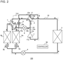
- FIG. 2 is an explanatory view for explanation of how the air-conditioning apparatus 100 according to Embodiment 1 is operated when the air-conditioning apparatus 100 is in the cooling operation.
- the first flow switching valve 2 and the second flow switching valve 7 are both set in the first state.
- the first valve 8 is opened to a predetermined opening degree, and the second valve 9 is closed.
- high-pressure gas refrigerant discharged from the compressor 1 branches into gas refrigerant that flows into the third port C of the first flow switching valve 2 and gas refrigerant that flows into the second high-pressure pipe 12b.
- the gas refrigerant that has flowed into the third port C of the first flow switching valve 2 passes through the second port B of the first flow switching valve 2 and the first port E and the fourth port H of the second flow switching valve 7, and flows into the first outdoor heat exchanger 6a.
- the gas refrigerant that has flowed into the second high-pressure pipe 12b passes through the first valve 8, the first pipe 15a, and the third port G and the second port F of the second flow switching valve 7, and flows into the second outdoor heat exchanger 6b.
- the first outdoor heat exchanger 6a and the second outdoor heat exchanger 6b both operate as condensers.
- the gas refrigerant that has flowed into the first outdoor heat exchanger 6a and the gas refrigerant that has flowed into the second outdoor heat exchanger 6b condense to change into liquid refrigerant.
- the liquid refrigerant that has flowed out of the first outdoor heat exchanger 6a is reduced in pressure at the first pressure reducing device 5a and flows into the expansion valve 4.
- the liquid refrigerant that has flowed out of the second outdoor heat exchanger 6b is reduced in pressure at the second pressure reducing device 5b, joins the liquid refrigerant that has flowed out of the first outdoor heat exchanger 6a, and then flows into the expansion valve 4.
- the liquid refrigerant that has flowed into the expansion valve 4 is reduced in pressure to change into low-pressure two-phase refrigerant.
- the two-phase refrigerant that has flowed out of the expansion valve 4 flows into the indoor heat exchanger 3. In the cooling operation, the indoor heat exchanger 3 operates as an evaporator.
- the refrigerant that flows in the indoor heat exchanger 3 receives heat from indoor air as evaporation heat.
- the two-phase refrigerant that has flowed into the indoor heat exchanger 3 evaporates to change into low-pressure gas refrigerant.
- the indoor air sent by the indoor fan transfers heat to the refrigerant and is thus cooled.
- the gas refrigerant that has flowed out of the indoor heat exchanger 3 passes through the fourth port D and the first port A of the first flow switching valve 2, the second low-pressure pipe 13b, and the first low-pressure pipe 13a, and is sucked into the compressor 1.
- the gas refrigerant that has sucked into the compressor 1 is compressed to change into high-pressure gas refrigerant. In the cooling operation, the above cycle is continuously repeated.
- FIG. 3 is an explanatory view for explanation of how the air-conditioning apparatus 100 according to Embodiment 1 is operated when the air-conditioning apparatus 100 is in the heating operation.
- the first flow switching valve 2 is set in the second state
- the second flow switching valve 7 is set in the first state.
- the second valve 9 is opened to a predetermined opening degree, and the first valve 8 is closed.
- High-pressure gas refrigerant discharged from the compressor 1 passes through the first high-pressure pipe 12a and the third port C and the fourth port D of the first flow switching valve 2, and flows into the indoor heat exchanger 3.
- the indoor heat exchanger 3 operates as a condenser. That is, at the indoor heat exchanger 3, the refrigerant that flows in the indoor heat exchanger 3 exchanges heat with indoor air sent by the indoor fan, and transfers heat to the indoor air as condensation heat. As a result, the gas refrigerant that has flowed into the indoor heat exchanger 3 condenses to change into high-pressure liquid refrigerant. The indoor air sent by the indoor fan is heated by the heat transferred from the refrigerant.
- the liquid refrigerant that flowed out of the indoor heat exchanger 3 flows into the expansion valve 4.
- the liquid refrigerant that has flowed into the expansion valve 4 is reduced in pressure to change into low-pressure two-phase refrigerant.
- the two-phase refrigerant that has flowed out of the expansion valve 4 branch into two-phase refrigerant that flows into the first pressure reducing device 5a and two-phase refrigerant that flows into the second pressure reducing device 5b.
- the two-phase refrigerant that has flowed into the first pressure reducing device 5a is further reduced in pressure and flows into the first outdoor heat exchanger 6a.
- the two-phase refrigerant that has flowed into the second pressure reducing device 5b is further reduced in pressure and flows into the second outdoor heat exchanger 6b.
- the first outdoor heat exchanger 6a and the second outdoor heat exchanger 6b both operate as condensers.
- refrigerant that flows in the outdoor heat exchanger exchanges heat with outdoor air sent by the outdoor fan and receives heat from the outdoor air as evaporation heat.
- the two-phase refrigerant that has flowed into each of the first outdoor heat exchanger 6a and the second outdoor heat exchanger 6b evaporates to change into low-pressure gas refrigerant.
- the gas refrigerant that has flowed out of the first outdoor heat exchanger 6a passes through the fourth port H and the first port E of the second flow switching valve 7, the second port B and the first port A of the first flow switching valve 2, the second low-pressure pipe 13b, and the first low-pressure pipe 13a, and is sucked into the compressor 1.
- the gas refrigerant that has flowed out of the second outdoor heat exchanger 6b passes through the second port F and the third port G of the second flow switching valve 7, the first pipe 15a, the second pipe 15b, and the second valve 9, joints the gas refrigerant that has flowed out of the first outdoor heat exchanger 6a, in the first low-pressure pipe 13a, and is sucked into the compressor 1.
- the gas refrigerant that has sucked into the compressor 1 is compressed to change into high-pressure gas refrigerant. In the heating operation, the above cycle is continuously repeated.
- the simultaneous heating and defrosting operation includes a first operation and a second operation.
- the first outdoor heat exchanger 6a and the indoor heat exchanger 3 operate as condensers
- the second outdoor heat exchanger 6b operates as an evaporator.
- the first outdoor heat exchanger 6a is defrosted while heating is being continued.
- the second outdoor heat exchanger 6b and the indoor heat exchanger 3 operate as condensers
- the first outdoor heat exchanger 6a operates as an evaporator.
- the second outdoor heat exchanger 6b is defrosted while heating is being continued.
- the controller 50 causes the simultaneous heating and defrosting operation to be performed.
- the requirement for the start of the simultaneous heating and defrosting operation for example, the following conditions are present: time that elapses from the start of the heating operation exceeds a threshold time, or the temperature of each of the first outdoor heat exchanger 6a and the second outdoor heat exchanger 6b reaches a threshold temperature or less.
- the controller 50 When the requirement for the start of the simultaneous heating and defrosting operation is satisfied, the controller 50 first causes the first operation to be performed, and then when elapsed time reaches predetermined time, or when the temperature of the first outdoor heat exchanger 6a exceeds the threshold temperature, the controller 50 causes the second operation to be performed.
- Fig. 4 is an explanatory view for explanation of how the air-conditioning apparatus 100 according to Embodiment 1 is operated when the air-conditioning apparatus 100 is in the first operation of the simultaneous heating and defrosting operation.
- the first flow switching valve 2 and the second flow switching valve 7 are both set in the second state.
- the first valve 8 is opened to a predetermined opening degree, and the second valve 9 is closed.
- High-pressure gas discharged from the compressor 1 branches into gas refrigerant that flows into the third port C of the first flow switching valve 2 and gas refrigerant that flows into the second high-pressure pipe 12b.
- the gas refrigerant that has flowed into the second high-pressure pipe 12b passes through the first valve 8, the first pipe 15a, and the third port G and the fourth port H of the second flow switching valve 7, and flows into the first outdoor heat exchanger 6a.
- frost adhering to the first outdoor heat exchanger 6a is molten by heat transferred from the refrigerant that flows in the first outdoor heat exchanger 6a.
- the first outdoor heat exchanger 6a is defrosted.
- the gas refrigerant that has flowed into the first outdoor heat exchanger 6a condenses to change into intermediate-pressure liquid refrigerant or two-phase refrigerant, flows out of the first outdoor heat exchanger 6a, and is reduced in pressure at the first pressure reducing device 5a.
- the gas refrigerant that has flowed into the third port C of the first flow switching valve 2 passes through the fourth port D of the first flow switching valve 2 and flows into the indoor heat exchanger 3.
- the refrigerant that flows in the indoor heat exchanger 3 exchanges heat with indoor air sent by the indoor fan, and transfers heat to the indoor air as condensation heat.
- the gas refrigerant that has flowed into the indoor heat exchanger 3 condenses to change into high-pressure liquid refrigerant.
- the indoor air sent by the indoor fan is heated by heat transferred from the refrigerant.
- the liquid refrigerant that has flowed out of the indoor heat exchanger 3 flows into the expansion valve 4.
- the liquid refrigerant that has flowed into the expansion valve 4 is reduced in pressure to change into low-pressure two-phase refrigerant.
- the two-phase refrigerant that has flowed out of the expansion valve 4 joins the liquid refrigerant or two-phase refrigerant that has been reduced in pressure at the first pressure reducing device 5a, is further reduced in pressure at the second pressure reducing device 5b, and flows into the second outdoor heat exchanger 6b.
- the refrigerant that flows in the second outdoor heat exchanger 6b exchanges heat with outdoor air sent by the outdoor fan, and receives heat from the outdoor air as evaporation heat.
- the two-phase refrigerant that has flowed into the second outdoor heat exchanger 6b evaporates to change into low-pressure gas refrigerant.
- the gas refrigerant that has flowed out of the second outdoor heat exchanger 6b passes through the second port F and the first port E of the second flow switching valve 7, the second port B and the first port A of the first flow switching valve 2, the second low-pressure pipe 13b, and the first low-pressure pipe 13a, and is sucked into the compressor 1.
- the gas refrigerant that has been sucked into the compressor 1 is compressed to change into high-pressure gas refrigerant.
- the above cycle is continuously repeated, whereby the first outdoor heat exchanger 6a is defrosted while heating is being continued.
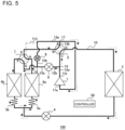
- Fig. 5 is an explanatory view for explanation of how the air-conditioning apparatus 100 according to Embodiment 1 is operated when the air-conditioning apparatus 100 is in the second operation of the simultaneous heating and defrosting operation.
- the first flow switching valve 2 is set in the second state
- the second flow switching valve 7 is set in the first state.
- the first valve 8 is opened to a predetermined opening degree, and the second valve 9 is closed.
- High-pressure gas refrigerant discharged from the compressor 1 branches, at the branch portion 14 of the first high-pressure pipe 12a, into gas refrigerant that flows into the third port C of the first flow switching valve 2 and gas refrigerant that flows into the second high-pressure pipe 12b.
- the gas refrigerant that has flowed into the second high-pressure pipe 12b passes through the first valve 8, the first pipe 15a, and the third port G and the second port F of the second flow switching valve 7, and flows into the second outdoor heat exchanger 6b.
- frost adhering to the second outdoor heat exchanger 6b is molten by heat transferred from the refrigerant that flows in the second outdoor heat exchanger 6b.
- the second outdoor heat exchanger 6b is defrosted.
- the gas refrigerant that has flowed into the second outdoor heat exchanger 6b condenses to change into intermediate-pressure liquid refrigerant or two-phase refrigerant, flows out of the second outdoor heat exchanger 6b as the intermediate-pressure liquid refrigerant or two-phase refrigerant, and is reduced in pressure at the second pressure reducing device 5b.
- the gas refrigerant that has flowed into the third port C of the first flow switching valve 2 passes through the fourth port D of the first flow switching valve 2 and flows into the indoor heat exchanger 3.
- the refrigerant that flows in the indoor heat exchanger 3 exchanges heat with indoor air sent by the indoor fan, and transfers heat to the indoor air as condensation heat.
- the gas refrigerant that has flowed into the indoor heat exchanger 3 condenses to change into high-pressure liquid refrigerant.
- the indoor air sent by the indoor fan is heated by the heat transferred from the refrigerant.
- the liquid refrigerant that has flowed out of the indoor heat exchanger 3 flows into the expansion valve 4.
- the liquid refrigerant that has flowed into the expansion valve 4 is reduced in pressure to change into low-pressure two-phase refrigerant.
- the two-phase refrigerant that has flowed out of the expansion valve 4 joins the liquid refrigerant or two-phase refrigerant that has been reduced in pressure at the second pressure reducing device 5b, is further reduced in pressure at the first pressure reducing device 5a, and flows into the first outdoor heat exchanger 6a.
- the refrigerant that flows in the first outdoor heat exchanger 6a exchanges heat with outdoor air sent by the outdoor fan, and receives heat from the outdoor fan as evaporation heat.
- the two-phase refrigerant that has flowed into the first outdoor heat exchanger 6a evaporates to change into low-pressure gas refrigerant.
- the gas refrigerant that has flowed out of the first outdoor heat exchanger 6a passes through the fourth port H and the first port E of the second flow switching valve 7, the second port B and the first port A of the first flow switching valve 2, the second low-pressure pipe 13b, and the first low-pressure pipe 13a, and is sucked into the compressor 1.
- the gas refrigerant that has been sucked into the compressor 1 is compressed to change into high-pressure gas refrigerant.
- the above cycle is continuously repeated, whereby the second outdoor heat exchanger 6b is defrosted while heating is being continued.
- the air-conditioning apparatus 100 is operated when the air-conditioning apparatus 100 is in the defrosting operation.
- the controller 50 causes the defrosting operation to be performed.
- the requirement for the start of the defrosting operation for example, the following conditions are present: a condition in which the heating load is low or no person is present in the air-conditioning target space, in addition to a condition in which the requirement for the start of the simultaneous heating and defrosting operation is satisfied.
- the operation of the air-conditioning apparatus 100 in the defrosting operation is the same as that in the cooling operation, which is illustrated in Fig. 2 .
- the first outdoor heat exchanger 6a and the second outdoor heat exchanger 6b both operate as condensers. That is, at each of the first outdoor heat exchanger 6a and the second outdoor heat exchanger 6b, frost adhering to the outdoor heat exchanger is molten by heat transferred by the refrigerant that flows in the outdoor heat exchanger. As a result, the first outdoor heat exchanger 6a and the second outdoor heat exchanger 6b are defrosted.
- FIG. 6 is a sectional view schematically illustrating a configuration of the second flow switching valve 7 according to Embodiment 1.
- the second flow switching valve 7 includes a main valve 70 and a pilot valve 71.
- the main valve 70 includes a cylinder 701, a slide rack 702 provided at part of an inner wall of the cylinder 701, and a slide valve 703 that is slid over the slide rack 702 along a central axis of the cylinder 701.
- the first port E is provided at a central portion of the slide rack 702 in a direction along the central axis of the cylinder 701.
- the second port F and the fourth port H are located opposite to each other with respect to the first port E in the direction along the central axis of the cylinder 701.
- the third port G is located opposite to the first port E with respect to the central axis of the cylinder 701.
- the slide valve 703 is formed in the shape of a dome having an opening that faces a side where the slide rack 702 is located.
- a piston 704 is provided such that the piston 704 is coupled to the slide valve 703.
- a first chamber 706 is provided between one end of the cylinder 701 and the piston 704.
- a piston 705 is provided such that the piston 705 is coupled to the slide valve 703.
- a second chamber 707 is provided between the other end of the cylinder 701 and the piston 705.
- the pistons 704 and 705 are provided such that the pistons 704 and 705 are slidable along an inner wall surface of the cylinder 701. The pistons 704 and 705 are moved together with the slide valve 703 in the direction along the central axis of the cylinder 701.
- the pilot valve 71 includes four pilot pipes 710, 711, 712, and 713.
- the pilot pipe 710 is connected with the third port G of the main valve 70;
- the pilot pipe 711 is connected with the first chamber 706 of the main valve 70;
- the pilot pipe 712 is connected with the second chamber 707 of the main valve 70;
- the pilot pipe 713 is connected with the first low-pressure pipe 13a.
- the state of the pilot valve 71 is switched by the controller 50 between a first state and a second state.
- the pilot pipe 710 and the pilot pipe 711 communicate with each other in the pilot valve 71
- the pilot pipe 713 and the pilot pipe 712 communicate with each other in the pilot valve 71.
- the third port G and the first chamber 706 communicate with each other, whereby the pressure in the first chamber 706 is substantially equalized to that in the third port G.
- the first low-pressure pipe 13a and the second chamber 707 communicate with each other, whereby the pressure in the second chamber 707 is substantially equalized to that in the first low-pressure pipe 13a.
- the slide valve 703 is moved by a differential pressure between the first chamber 706 and the second chamber 707. In the first state, the slide valve 703 is moved toward the second chamber 707, which is lower in pressure than the first chamber 706. As a result, the first port E and the fourth port H communicate with each other, the third port G and the second port F communicate with each other, and the state of the second flow switching valve 7 is switched to the first state.
- the pilot pipe 710 and the pilot pipe 712 communicate with each other in the pilot valve 71, and the pilot pipe 711 and the pilot pipe 713 communicate with each other in the pilot valve 71.
- the third port G and the second chamber 707 communicate with each other, whereby the pressure in the second chamber 707 is substantially equalized to that in the third port G.
- the first low-pressure pipe 13a and the first chamber 706 communicate with each other, whereby the pressure in the first chamber 706 is substantially equalized to that in the first low-pressure pipe 13a.
- the slide valve 703 is moved toward the first chamber 706, which is lower in pressure than the second chamber 707.
- the first port E and the second port F communicate with each other
- the third port G and the fourth port H communicate with each other
- the state of the second flow switching valve 7 is switched to the second state.
- Fig. 7 is a p-h diagram of the air-conditioning apparatus 100 according to Embodiment 1.
- the pilot pipe 713 of the pilot valve 71 is connected with the first port E of the main valve 70.
- a differential pressure D po between the third port G and the first port E is thus a pressure loss in the second flow switching valve 7 and decreases. Consequently, it is not possible to ensure a sufficient differential pressure for movement and fixation of the slide valve 703.
- the following failure may occur: the state of the slide valve 703 cannot be switched, or the position of the slide valve 703 is shifted during the operation.
- the pilot pipe 713 of the second flow switching valve 7 is connected with the first low-pressure pipe 13a, whereby in the cooling operation also, it is possible to obtain a great differential pressure D p1 between the third port G and the first low-pressure pipe 13a. As a result, it is possible to ensure a differential pressure between the first chamber 706 and the second chamber 707 and reliably move and fix the slide valve 703.
- the first chamber 706 or the second chamber 707 of the second flow switching valve 7 is connected with the first low-pressure pipe 13a in which low-pressure refrigerant flows, via the pilot valve 71, whereby it is possible to ensure a minimum operating differential pressure in the second flow switching valve 7. As a result, the second flow switching valve 7 can be normally operated.
- An air-conditioning apparatus 100 according to Embodiment 2 will be described.
- the configuration of the second flow switching valve 7 is different from that in Embodiment 1.
- the other configurations and controls in the air-conditioning apparatus 100 according to Embodiment 2 are the same as those in Embodiment 1.
- Fig. 8 is a sectional view schematically illustrating a configuration of a second flow switching valve 7A according to Embodiment 2.
- the pilot pipe 713 of the second flow switching valve 7A is connected with the first port E; and the second chamber 707 of the main valve 70 of the second flow switching valve 7A is connected with the first low-pressure pipe 13a by a pipe 721 and a third valve 722. That is, in Embodiment 2, the second chamber 707 of the second flow switching valve 7A is connected with the first low-pressure pipe 13a without communicating with the pilot valve 71.
- the third valve 722 is a solenoid valve or an electronic expansion valve that adjusts the flow rate of refrigerant flowing from the first low-pressure pipe 13a to the second chamber 707, and the opening degree of the third valve 722 is controlled by the controller 50.
- the third valve 722 is opened by the controller 50, the first low-pressure pipe 13a and the second chamber 707 communicate with each other, and as a result, the pressure in the second chamber 707 is substantially equalized to that in the first low-pressure pipe 13a.
- the slide valve 703 is moved by a differential pressure between the first chamber 706 and the second chamber 707, and the state of the second flow switching valve 7A is switched.
- the second chamber 707 is connected with the first low-pressure pipe 13a without communicating with the pilot valve 71. In this case also, it is possible to ensure a minimum operating differential pressure in the second flow switching valve 7A, and reliably move and fix the slide valve 703. Thus, the second flow switching valve 7A can be normally operated.
- Fig. 8 illustrates an example in which the second chamber 707 is connected with the first low-pressure pipe 13a without communicating with the pilot valve 71
- the first chamber 706 may be connected with the first low-pressure pipe 13a without communicating with the pilot valve 71, or each of the first chamber 706 and the second chamber 707 may be connected with the first low-pressure pipe 13a without communicating with the pilot valve 71.
- An air-conditioning apparatus 100 according to Embodiment 3 will be described.
- the configuration of the second flow switching valve 7 is different from that in Embodiment 1.
- the other configurations and controls in the air-conditioning apparatus 100 according to Embodiment 3 are the same as those in Embodiment 1.
- Fig. 9 is a sectional view schematically illustrating a configuration of a second flow switching valve 7B according to Embodiment 3. As illustrated in Fig. 9 , in Embodiment 3, the pilot pipe 713 of the second flow switching valve 7B is connected with the first port E, and the pilot pipe 710 of the second flow switching valve 7B is connected with the second high-pressure pipe 12b of the refrigerant circuit 10.
- low-pressure refrigerant flows into both the third port G and the first port E.
- the pilot pipe 710 of the pilot valve 71 is connected with the third port G of the main valve 70.
- the differential pressure between the third port G and the first port E is only the differential pressure loss in the second flow switching valve 7 and it may be impossible to ensure a sufficient differential pressure for movement and fixation of the slide valve 703.
- the first chamber 706 or the second chamber 707 of the second flow switching valve 7B is connected with the first low-pressure pipe 13a via the pilot valve 71, whereby in the heating operation also, it is possible to ensure a great differential pressure between the first port E and the second high-pressure pipe 12b.
- the second flow switching valve 7B can be normally operated.
- An air-conditioning apparatus 100 according to Embodiment 4 will be described.
- the configuration of the second flow switching valve 7 is different from that in Embodiment 1.
- the other configurations and controls in the air-conditioning apparatus 100 are the same as those in Embodiment 1.
- Fig. 10 is a sectional view schematically illustrating a configuration of a second flow switching valve 7C according to Embodiment 4.
- the pilot pipe 710 is connected with the third port G
- the pilot pipe 713 is connected with the first port E.
- the first chamber 706 of the main valve 70 is connected with the second high-pressure pipe 12b by a pipe 731 and a fourth valve 732. That is, in Embodiment 4, the first chamber 706 of the second flow switching valve 7C is connected with the second high-pressure pipe 12b without communicating with a pilot valve 41.
- the fourth valve 732 is a solenoid valve or an electronic expansion valve that adjusts the flow rate of refrigerant flowing from the second high-pressure pipe 12b into the first chamber 706, and the opening degree of the fourth valve 732 is controlled by the controller 50.
- the fourth valve 732 is opened by the controller 50, the second high-pressure pipe 12b and the first chamber 706 communicate with each other, and as a result, the pressure in the first chamber 706 is substantially equalized to that in the second high-pressure pipe 12b.
- the slide valve 703 is moved by the differential pressure between the first chamber 706 and the second chamber 707, and the state of the second flow switching valve 7C is switched.
- the first chamber 706 is connected with the second high-pressure pipe 12b without communicating with the pilot valve 71.
- the second flow switching valve 7C can be normally operated.
- Fig. 9 illustrates an example in which the first chamber 706 of the second flow switching valve 7C is connected with the second high-pressure pipe 12b without communicating with the pilot valve 71
- the second chamber 707 may be connected with the second high-pressure pipe 12b without communicating with the pilot valve 71, or each of the first chamber 706 and the second chamber 707 may be connected with the second high-pressure pipe 12b without communicating with the pilot valve 71.
- An air-conditioning apparatus 100A according to Embodiment 5 will be described.
- the configuration of the second flow switching valve 7 is different from that in Embodiment 1.
- the other configurations and controls of the air-conditioning apparatus 100A according to Embodiment 5 are the same as those in Embodiment 1.
- Fig. 11 is a refrigerant circuit diagram illustrating a configuration of the air-conditioning apparatus 100A according to Embodiment 5.
- the air-conditioning apparatus 100A of Embodiment 5 does not include the second valve 9.
- the suction inlet 11a of the compressor 1 and the first port A of the first flow switching valve 2 are connected with each other by the first low-pressure pipe 13a.
- the air-conditioning apparatus 100A includes a second flow switching valve 7D that switches a flow passage for the refrigerant between a flow passage through the refrigerant flows to the first outdoor heat exchanger 6a and a flow passage through the refrigerant flows to the second outdoor heat exchanger 6b.
- the second flow switching valve 7D is a differential pressure drive type of four-way valve that is operated by a differential pressure as in the second flow switching valve according to each of Embodiments 1 to 4.
- the second flow switching valve 7D has a first port E, a second port F, a third port G, and a fourth port H.
- the second flow switching valve 7D of Embodiment 5 can enter a first state, a second state, and a third state. In the first state, the first port E, the second port F, and the fourth port H communicate with each other, and the third port G is closed. In the second state, the first port E and the second port F communicate with each other, and the third port G and the fourth port H communicate with each other. In the third state, the second port F and the third port G communicate with each other, and the first port E and the fourth port H communicate with each other.
- the second flow switching valve 7D In each of the cooling operation, the defrosting operation, and the heating operation, the second flow switching valve 7D is set in the first state; in the first operation of the simultaneous heating and defrosting operation, the second flow switching valve 7D is set in the second state; and in the second operation of the simultaneous heating and defrosting operation, the second flow switching valve 7D is set in the third state.
- the second flow switching valve 7D At least one of the first chamber 706 and the second chamber 707, between which a differential pressure is generated, is connected with the first low-pressure pipe 13a or the second high-pressure pipe 12b.
- the pilot pipe 713 of the second flow switching valve 7D is connected with the first low-pressure pipe 13a, or the second chamber 707 of the second flow switching valve 7D is connected with the first low-pressure pipe 13a.
- the pilot pipe 710 of the second flow switching valve 7D is connected with the second high-pressure pipe 12b, or the first chamber 706 of the second flow switching valve 7D is connected with the second high-pressure pipe 12b.
- the second flow switching valve 7D can enter three states as in Embodiment 5, by connecting at least one of the first chamber 706 and the second chamber 707 with the first low-pressure pipe 13a or the second high-pressure pipe 12b, it is possible to ensure a minimum operating differential pressure in the second flow switching valve 7D. As a result, the second flow switching valve 7D can be normally operated.
- connection of the pilot pipe 713 of Embodiment 1 and the second chamber 707 of Embodiment 2 it suffices that the pilot pipe 713 of Embodiment 1 and the second chamber 707 of Embodiment 2 are each connected to a low-pressure portion whichever of the operations is performed in the refrigerant circuit 10, and the pilot pipe 713 of Embodiment 1 and the second chamber 707 of Embodiment 2 may be each connected with the second low-pressure pipe 13b or any of the other low-pressure pipes, instead of with the first low-pressure pipe 13a.
- pilot pipe 710 of Embodiment 3 and the first chamber 706 of Embodiment 4 are each connected to a low-pressure portion whichever of the operations is performed in the refrigerant circuit 10, and the pilot pipe 710 of Embodiment 3 and the first chamber 706 of Embodiment 4 may be connected with the first high-pressure pipe 12a or any of the other high-pressure pipes, instead of with the second high-pressure pipe 12b.
- Embodiments 1 to 5 can be combined arbitrarily.
- the second flow switching valve 7 may be configured such that the pilot pipe 713 is connected with the first low-pressure pipe 13a and the pilot pipe 710 is connected with the second high-pressure pipe 12b.
- the second flow switching valve 7 may be configured such the second chamber 707 is connected with the first low-pressure pipe 13a and the first chamber 706 is connected with the second high-pressure pipe 12b.
- the second flow switching valve 7 may be configured such that the pilot pipe 713 is connected with the first low-pressure pipe 13a and the first chamber 706 is connected with the second high-pressure pipe 12b.
- the second flow switching valve 7 may be configured such that the second chamber 707 is connected with the first low-pressure pipe 13a and the pilot pipe 710 is connected with the second high-pressure pipe 12b. That is, it suffices that part of the second flow switching valve 7 that is other than the ports is connected to any one of the low-pressure pipes and the high-pressure pipes in the refrigerant circuit 10.
Landscapes
- Engineering & Computer Science (AREA)
- Mechanical Engineering (AREA)
- General Engineering & Computer Science (AREA)
- Physics & Mathematics (AREA)
- Thermal Sciences (AREA)
- Chemical & Material Sciences (AREA)
- Combustion & Propulsion (AREA)
- Fluid Mechanics (AREA)
- Compression-Type Refrigeration Machines With Reversible Cycles (AREA)
- Air Conditioning Control Device (AREA)
Abstract
Description
- The present disclosure relates to an air conditioning apparatus capable of performing a simultaneous heating and defrosting operation.
- In the past, air-conditioning apparatuses capable of performing a heating operation and a defrosting operation at the same time have been known. Patent Literature 1 discloses an air-conditioning apparatus in which a first heat exchange unit and a second heat exchange unit provided in an outdoor heat exchanger are alternately defrosted, whereby the outdoor heat exchanger can be defrosted without stopping a heating operation.
- Patent Literature 1: International Publication No.
2019/003291 - An existing air-conditioning apparatus uses a differential pressure drive type of flow switching valve that switches a flow passage between a flow passage to a first heat exchange unit and a flow passage to a second heat exchange unit. In this case, in an operation in which high-pressure refrigerant flows in the entire region of the flow switching valve as in a cooling operation or low-pressure refrigerant flows in the entire region of the flow switching valve as in a heating operation, it is not possible to ensure a sufficient differential pressure necessary for the flow switching valve to switch the flow passage and to be fixed.
- The present disclosure is applied to solve the above problem, and an object according to the present disclosure is to ensure a differential pressure in a flow switching valve in an air-conditioning apparatus capable of performing a simultaneous heating and defrosting operation.
- An air-conditioning apparatus according to an embodiment of the present disclosure includes a refrigerant circuit that includes a compressor, a high-pressure pipe through which high-pressure refrigerant discharged from the compressor flows, a low-pressure pipe through which low-pressure refrigerant to be sucked into the compressor flows, a first flow switching valve, an indoor heat exchanger, an expansion valve, a first outdoor heat exchanger, a second outdoor heat exchanger, and a second flow switching valve. The second flow switching valve switches flow passages for refrigerant flowing to the first outdoor heat exchanger and the second outdoor heat exchanger. The second flow switching valve includes a first chamber, a second chamber, and a slide valve configured to be moved by a differential pressure between the first chamber and the second chamber. At least one of the first chamber and the second chamber is connected with the high-pressure pipe or the low-pressure pipe.
- According to the present disclosure, one of the first chamber and the second chamber, between which a differential pressure is generated in the second flow switching valve, is connected with the high-pressure pipe or the low-pressure pipe, whereby it is possible to ensure a sufficient differential pressure for switching and fixation of the second flow switching valve.
-
- [
Fig. 1] Fig. 1 is a refrigerant circuit diagram illustrating a configuration of an air-conditioning apparatus according to Embodiment 1. - [
Fig. 2] Fig. 2 is an explanatory view for explanation of how the air-conditioning apparatus according to Embodiment 1 is operated when the air-conditioning apparatus 100 is in a cooling operation. - [
Fig. 3] Fig. 3 is an explanatory view for explanation of how the air-conditioning apparatus 100 according to Embodiment 1 is operated when the air-conditioning apparatus 100 is in a heating operation. - [
Fig. 4] Fig. 4 is an explanatory view for explanation of how the air-conditioning apparatus according to Embodiment 1 is operated when the air-conditioning apparatus is in a first operation of a simultaneous heating and defrosting operation. - [
Fig. 5] Fig. 5 is an explanatory view for explanation of how the air-conditioning apparatus according to Embodiment 1 is operated when the air-conditioning apparatus is in a second operation of the simultaneous heating and defrosting operation. - [
Fig. 6] Fig. 6 is a sectional view schematically illustrating a configuration of a second flow switching valve according to Embodiment 1. - [
Fig. 7] Fig. 7 is a p-h diagram of the air-conditioning apparatus according to Embodiment 1. - [
Fig. 8] Fig. 8 is a sectional view schematically illustrating a configuration of a second flow switching valve according toEmbodiment 2. - [
Fig. 9] Fig. 9 is a sectional view schematically illustrating a configuration of a second flow switching valve according toEmbodiment 3. - [
Fig. 10] Fig. 10 is a sectional view schematically illustrating a configuration of a second flow switching valve according toEmbodiment 4. - [
Fig. 11] Fig. 11 is a refrigerant circuit diagram illustrating a configuration of an air-conditioning apparatus according to Embodiment 5. - An air-
conditioning apparatus 100 according to Embodiment 1 will be described. The air-conditioning apparatus 100 is a room air conditioner installed at a wall in an air-conditioning target space or an all-in-on air-conditioning system installed at a ceiling located above the air-conditioning target space. The air-conditioning apparatus 100 is capable of performing a cooling operation, a heating operation, a reverse cycle defrosting operation (hereinafter simply referred to as "defrosting operation"), and a simultaneous heating and defrosting operation. -
Fig. 1 is a refrigerant circuit diagram illustrating a configuration of the air-conditioning apparatus 100 according to Embodiment 1. As illustrated inFig. 1 , the air-conditioning apparatus 100 includes arefrigerant circuit 10 and acontroller 50 that controls therefrigerant circuit 10. Therefrigerant circuit 10 includes a compressor 1, a firstflow switching valve 2, anindoor heat exchanger 3, anexpansion valve 4, a firstpressure reducing device 5a, a secondpressure reducing device 5b, a firstoutdoor heat exchanger 6a, a secondoutdoor heat exchanger 6b, a secondflow switching valve 7, afirst valve 8, and asecond valve 9. - The compressor 1 is a fluid machine that sucks low-pressure gas refrigerant, compresses the low-pressure gas refrigerant to change it into high-pressure gas refrigerant, and discharges the high-pressure gas refrigerant. The compressor 1 is an inverter drive compressor whose operating frequency can be adjusted. The operating frequency of the compressor 1 is controlled by the
controller 50. The compressor 1 has asuction inlet 11a through which refrigerant is sucked and a discharge outlet through which compressed refrigerant is discharged. Thesuction inlet 11a is kept at a suction pressure, that is, a low pressure, and thedischarge outlet 11b is kept at a discharge pressure, that is, a high pressure. - The first
flow switching valve 2 is a four-way valve that switches a flow passage for refrigerant discharged from the compressor 1 between a plurality of flow passages. The firstflow switching valve 2 has a first port A, a second port B, a third port C, and a fourth port D. The first port A is a low-pressure port that is kept at a low pressure whichever of the cooling operation, the heating operation, the defrosting operation, and the simultaneous heating and defrosting operation is performed. The third port C is a high-pressure port that is kept at a high pressure whichever of the cooling operation, the heating operation, the defrosting operation, and the simultaneous heating and defrosting operation is performed. The firstflow switching valve 2 can enter a first state indicated by solid lines inFig. 1 and a second state indicated by broken lines inFig. 1 . When the firstflow switching valve 2 is in the first state, the first port A and the fourth port D communicate with each other and the second port B and the third port C communicate with each other. When the firstflow switching valve 2 is in the second state, the first port A and the second port B communicate with each other and the third port C and the fourth port D communicate with each other. In the cooling operation or the defrosting operation, thecontroller 50 sets the state of the firstflow switching valve 2 to the first state, and in the heating operation or the simultaneous heating and defrosting operation, thecontroller 50 sets the state of the firstflow switching valve 2 to the second state. - The
indoor heat exchanger 3 is a heat exchanger that transfers heat between refrigerant that flows in theindoor heat exchanger 3 and air send by an indoor fan (not illustrated) provided in an indoor unit. Theindoor heat exchanger 3 operates as a condenser in the heating operation and operates as an evaporator in the cooling operation. - The
expansion valve 4 is an electronic expansion valve that reduces the pressure of the refrigerant. The opening degree of theexpansion valve 4 is adjusted by thecontroller 50. - The first
pressure reducing device 5a and the secondpressure reducing device 5b are respective capillary tubes that reduce the pressure of refrigerant flowing between theexpansion valve 4 and the firstoutdoor heat exchanger 6a and the pressure of refrigerant flowing between theexpansion valve 4 and the secondoutdoor heat exchanger 6b. The firstpressure reducing device 5a is provided at the firstoutdoor heat exchanger 6a on an outflow side for the refrigerant in the cooling operation, and the secondpressure reducing device 5b is provided at the secondoutdoor heat exchanger 6b on an outflow side for the refrigerant in the cooling operation. - The first
outdoor heat exchanger 6a and the secondoutdoor heat exchanger 6b are each a heat exchanger that transfers heat between refrigerant flowing in the heat exchanger and air sent by an outdoor fan (not illustrated) provided in an outdoor unit. Each of the firstoutdoor heat exchanger 6a and the secondoutdoor heat exchanger 6b operates as an evaporator in the heating operation and operates as a condenser in the cooling operation. The firstoutdoor heat exchanger 6a and the secondoutdoor heat exchanger 6b are connected in parallel with each other in therefrigerant circuit 10. The firstoutdoor heat exchanger 6a and the secondoutdoor heat exchanger 6b are outdoor heat exchangers into which, for example, a single heat exchanger is divided, and which are arranged one above the other. For example, the firstoutdoor heat exchanger 6a is located on a lower side, and the secondoutdoor heat exchanger 6b is located on an upper side. In this case, the firstoutdoor heat exchanger 6a and the secondoutdoor heat exchanger 6b are also arranged in parallel with each other for the flow of air. - The second
flow switching valve 7 switches the flow passage for the refrigerant between a flow passage through which the refrigerant flows to the firstoutdoor heat exchanger 6a and a flow passage through which the refrigerant flows to the secondoutdoor heat exchanger 6b. The secondflow switching valve 7 is a differential pressure drive type of four-way valve that is operated by a differential pressure. The secondflow switching valve 7 has a first port E, a second port F, a third port G, and a fourth port H. The secondflow switching valve 7 can enter a first state indicated by solid lines inFig. 1 and a second state indicated by broken lines inFig. 1 . When the secondflow switching valve 7 is in the first state, the first port E and the fourth port H communicate with each other and the second port F and the third port G communicate with each other. When the secondflow switching valve 7 is in the second state, the first port E and the second port F communicate with each other and the third port G and the fourth port H communicate with each other. In the simultaneous heating and defrosting operation, thecontroller 50 sets the state of the secondflow switching valve 7 to the first state or the second state. - The
first valve 8 is a solenoid valve or an electronic expansion valve that adjusts the flow rate of refrigerant that flows from thedischarge outlet 11b of the compressor 1 to the third port G of the secondflow switching valve 7. The opening degree of thefirst valve 8 is adjusted by thecontroller 50. - The
second valve 9 is a solenoid valve or an electronic expansion valve that adjusts the flow rate of refrigerant that flows from the third port G of the secondflow switching valve 7 to thesuction inlet 11a of the compressor 1. The opening degree of thesecond valve 9 is adjusted by thecontroller 50. - The
discharge outlet 11b of the compressor 1 is connected with the third port C of the firstflow switching valve 2 by a first high-pressure pipe 12a. In the first high-pressure pipe 12a, high-pressure refrigerant discharged from thedischarge outlet 11b of the compressor 1 flows whichever of the cooling operation, the heating operation, the defrosting operation, and the simultaneous heating and defrosting operation is performed. - A
branch portion 14 provided at an intermediate portion of the first high-pressure pipe 12a is connected with thefirst valve 8 by a second high-pressure pipe 12b. Also, in the second high-pressure pipe 12b, the high-pressure refrigerant discharged from thedischarge outlet 11b of the compressor 1 flows whichever of the cooling operation, the heating operation, the defrosting operation, and the simultaneous heating and defrosting operation is performed. Thefirst valve 8 is connected with the third port G of the secondflow switching valve 7 by afirst pipe 15a. That is, the third port G of the secondflow switching valve 7 is connected with thedischarge outlet 11b of the compressor 1 by thefirst pipe 15a, thefirst valve 8, the second high-pressure pipe 12b, and the first high-pressure pipe 12a. Abranch portion 16 provided at an intermediate portion of thefirst pipe 15a is connected with thesecond valve 9 by asecond pipe 15b. - The
suction inlet 11a of the compressor 1 is connected with thesecond valve 9 by a first low-pressure pipe 13a. In the first low-pressure pipe 13a, low-pressure refrigerant that is to be sucked from thesuction inlet 11a of the compressor 1 flows whichever of the cooling operation, the heating operation, the defrosting operation, and the simultaneous heating and defrosting operation is performed. Furthermore, to the first low-pressure pipe 13a, apilot pipe 713 of the secondflow switching valve 7 is connected. Abranch portion 17 provided at an intermediate portion of the first low-pressure pipe 13a is connected with the first port A of the firstflow switching valve 2 by a second low-pressure pipe 13b. - The fourth port D of the first
flow switching valve 2 is connected with one port of theindoor heat exchanger 3 by a refrigerant pipe, and the other port of theindoor heat exchanger 3 is connected with one port of theexpansion valve 4 by a refrigerant pipe. - The other port of the
expansion valve 4 is connected with the firstpressure reducing device 5a and the secondpressure reducing device 5b by respective refrigerant pipes. The firstpressure reducing device 5a and the secondpressure reducing device 5b are connected with the firstoutdoor heat exchanger 6a and the secondoutdoor heat exchanger 6b, respectively. That is, the other port of theexpansion valve 4 is connected with one port of the firstoutdoor heat exchanger 6a and one port of the secondoutdoor heat exchanger 6b via the refrigerant pipes and the firstpressure reducing device 5a and the secondpressure reducing device 5b. Furthermore, the one port of the firstoutdoor heat exchanger 6a is connected with the one port of the secondoutdoor heat exchanger 6b by a refrigerant pipe. - The other port of the first
outdoor heat exchanger 6a is connected with the fourth port H of the secondflow switching valve 7 by a refrigerant pipe. The other port of the secondoutdoor heat exchanger 6b is connected with the second port F of the secondflow switching valve 7 by a refrigerant pipe. The first port E of the secondflow switching valve 7 is connected with the second port B of the firstflow switching valve 2 by a refrigerant pipe. - The
controller 50 includes a microcomputer provided with a CPU, a ROM, a RAM, an I/O port, etc. Thecontroller 50 controls components of the air-conditioning apparatus 100 to cause any of the cooling operation, the heating operation, the defrosting operation, and the simultaneous heating and defrosting operation to be performed, based on detection signals sent from various sensors (not illustrated) provided in the air-conditioning apparatus 100 and set information input from the remote controller. To be more specific, thecontroller 50 controls the operating frequency of the compressor 1, switching of the state of each of the firstflow switching valve 2 and the secondflow switching valve 7, the opening degree of each of theexpansion valve 4, thefirst valve 8, and the second valve, and the rotating speed of each of the fans. The various sensors provided in the air-conditioning apparatus 100 are an indoor temperature sensor that detects the temperature of the air-conditioning target space, an outside air temperature sensor that detects an outside air temperature, sensors that detect the temperatures or pressures of refrigerant flowing in the respective heat exchangers, a sensor that detects presence or absence of a person or persons in the air-conditioning target space, etc. - It will be described how the air-
conditioning apparatus 100 is operated when the air-conditioning apparatus 100 is in the cooling operation.Fig. 2 is an explanatory view for explanation of how the air-conditioning apparatus 100 according to Embodiment 1 is operated when the air-conditioning apparatus 100 is in the cooling operation. As illustrated inFig. 2 , in the cooling operation, the firstflow switching valve 2 and the secondflow switching valve 7 are both set in the first state. Furthermore, thefirst valve 8 is opened to a predetermined opening degree, and thesecond valve 9 is closed. - At the
branch portion 14 of the first high-pressure pipe 12a, high-pressure gas refrigerant discharged from the compressor 1 branches into gas refrigerant that flows into the third port C of the firstflow switching valve 2 and gas refrigerant that flows into the second high-pressure pipe 12b. The gas refrigerant that has flowed into the third port C of the firstflow switching valve 2 passes through the second port B of the firstflow switching valve 2 and the first port E and the fourth port H of the secondflow switching valve 7, and flows into the firstoutdoor heat exchanger 6a. The gas refrigerant that has flowed into the second high-pressure pipe 12b passes through thefirst valve 8, thefirst pipe 15a, and the third port G and the second port F of the secondflow switching valve 7, and flows into the secondoutdoor heat exchanger 6b. In the cooling operation, the firstoutdoor heat exchanger 6a and the secondoutdoor heat exchanger 6b both operate as condensers. The gas refrigerant that has flowed into the firstoutdoor heat exchanger 6a and the gas refrigerant that has flowed into the secondoutdoor heat exchanger 6b condense to change into liquid refrigerant. - The liquid refrigerant that has flowed out of the first
outdoor heat exchanger 6a is reduced in pressure at the firstpressure reducing device 5a and flows into theexpansion valve 4. The liquid refrigerant that has flowed out of the secondoutdoor heat exchanger 6b is reduced in pressure at the secondpressure reducing device 5b, joins the liquid refrigerant that has flowed out of the firstoutdoor heat exchanger 6a, and then flows into theexpansion valve 4. The liquid refrigerant that has flowed into theexpansion valve 4 is reduced in pressure to change into low-pressure two-phase refrigerant. The two-phase refrigerant that has flowed out of theexpansion valve 4 flows into theindoor heat exchanger 3. In the cooling operation, theindoor heat exchanger 3 operates as an evaporator. That is, at theindoor heat exchanger 3, the refrigerant that flows in theindoor heat exchanger 3 receives heat from indoor air as evaporation heat. As a result, the two-phase refrigerant that has flowed into theindoor heat exchanger 3 evaporates to change into low-pressure gas refrigerant. On the other hand, the indoor air sent by the indoor fan transfers heat to the refrigerant and is thus cooled. The gas refrigerant that has flowed out of theindoor heat exchanger 3 passes through the fourth port D and the first port A of the firstflow switching valve 2, the second low-pressure pipe 13b, and the first low-pressure pipe 13a, and is sucked into the compressor 1. The gas refrigerant that has sucked into the compressor 1 is compressed to change into high-pressure gas refrigerant. In the cooling operation, the above cycle is continuously repeated. - It will be described how the air-
conditioning apparatus 100 is operated when the air-conditioning apparatus 100 is in the heating operation.Fig. 3 is an explanatory view for explanation of how the air-conditioning apparatus 100 according to Embodiment 1 is operated when the air-conditioning apparatus 100 is in the heating operation. As illustrated inFig. 3 , in the heating operation, the firstflow switching valve 2 is set in the second state, and the secondflow switching valve 7 is set in the first state. Furthermore, thesecond valve 9 is opened to a predetermined opening degree, and thefirst valve 8 is closed. - High-pressure gas refrigerant discharged from the compressor 1 passes through the first high-
pressure pipe 12a and the third port C and the fourth port D of the firstflow switching valve 2, and flows into theindoor heat exchanger 3. In the heating operation, theindoor heat exchanger 3 operates as a condenser. That is, at theindoor heat exchanger 3, the refrigerant that flows in theindoor heat exchanger 3 exchanges heat with indoor air sent by the indoor fan, and transfers heat to the indoor air as condensation heat. As a result, the gas refrigerant that has flowed into theindoor heat exchanger 3 condenses to change into high-pressure liquid refrigerant. The indoor air sent by the indoor fan is heated by the heat transferred from the refrigerant. - The liquid refrigerant that flowed out of the
indoor heat exchanger 3 flows into theexpansion valve 4. The liquid refrigerant that has flowed into theexpansion valve 4 is reduced in pressure to change into low-pressure two-phase refrigerant. The two-phase refrigerant that has flowed out of theexpansion valve 4 branch into two-phase refrigerant that flows into the firstpressure reducing device 5a and two-phase refrigerant that flows into the secondpressure reducing device 5b. The two-phase refrigerant that has flowed into the firstpressure reducing device 5a is further reduced in pressure and flows into the firstoutdoor heat exchanger 6a. The two-phase refrigerant that has flowed into the secondpressure reducing device 5b is further reduced in pressure and flows into the secondoutdoor heat exchanger 6b. - In the heating operation, the first
outdoor heat exchanger 6a and the secondoutdoor heat exchanger 6b both operate as condensers. At each of the firstoutdoor heat exchanger 6a and the secondoutdoor heat exchanger 6b, refrigerant that flows in the outdoor heat exchanger exchanges heat with outdoor air sent by the outdoor fan and receives heat from the outdoor air as evaporation heat. As a result, the two-phase refrigerant that has flowed into each of the firstoutdoor heat exchanger 6a and the secondoutdoor heat exchanger 6b evaporates to change into low-pressure gas refrigerant. - The gas refrigerant that has flowed out of the first
outdoor heat exchanger 6a passes through the fourth port H and the first port E of the secondflow switching valve 7, the second port B and the first port A of the firstflow switching valve 2, the second low-pressure pipe 13b, and the first low-pressure pipe 13a, and is sucked into the compressor 1. The gas refrigerant that has flowed out of the secondoutdoor heat exchanger 6b passes through the second port F and the third port G of the secondflow switching valve 7, thefirst pipe 15a, thesecond pipe 15b, and thesecond valve 9, joints the gas refrigerant that has flowed out of the firstoutdoor heat exchanger 6a, in the first low-pressure pipe 13a, and is sucked into the compressor 1. The gas refrigerant that has sucked into the compressor 1 is compressed to change into high-pressure gas refrigerant. In the heating operation, the above cycle is continuously repeated. - It will be described how the air-
conditioning apparatus 100 is operated when the air-conditioning apparatus 100 is in the simultaneous heating and defrosting operation. The simultaneous heating and defrosting operation includes a first operation and a second operation. In the first operation, the firstoutdoor heat exchanger 6a and theindoor heat exchanger 3 operate as condensers, and the secondoutdoor heat exchanger 6b operates as an evaporator. As a result, the firstoutdoor heat exchanger 6a is defrosted while heating is being continued. In the second operation, the secondoutdoor heat exchanger 6b and theindoor heat exchanger 3 operate as condensers, and the firstoutdoor heat exchanger 6a operates as an evaporator. As a result, the secondoutdoor heat exchanger 6b is defrosted while heating is being continued. - In the case where the heating operation is performed, when a requirement for a start of the simultaneous heating and defrosting operation is satisfied, the
controller 50 causes the simultaneous heating and defrosting operation to be performed. As the requirement for the start of the simultaneous heating and defrosting operation, for example, the following conditions are present: time that elapses from the start of the heating operation exceeds a threshold time, or the temperature of each of the firstoutdoor heat exchanger 6a and the secondoutdoor heat exchanger 6b reaches a threshold temperature or less. When the requirement for the start of the simultaneous heating and defrosting operation is satisfied, thecontroller 50 first causes the first operation to be performed, and then when elapsed time reaches predetermined time, or when the temperature of the firstoutdoor heat exchanger 6a exceeds the threshold temperature, thecontroller 50 causes the second operation to be performed. -
Fig. 4 is an explanatory view for explanation of how the air-conditioning apparatus 100 according to Embodiment 1 is operated when the air-conditioning apparatus 100 is in the first operation of the simultaneous heating and defrosting operation. As illustrated inFig. 4 , in the first operation, the firstflow switching valve 2 and the secondflow switching valve 7 are both set in the second state. Furthermore, thefirst valve 8 is opened to a predetermined opening degree, and thesecond valve 9 is closed. - High-pressure gas discharged from the compressor 1 branches into gas refrigerant that flows into the third port C of the first
flow switching valve 2 and gas refrigerant that flows into the second high-pressure pipe 12b. The gas refrigerant that has flowed into the second high-pressure pipe 12b passes through thefirst valve 8, thefirst pipe 15a, and the third port G and the fourth port H of the secondflow switching valve 7, and flows into the firstoutdoor heat exchanger 6a. At the firstoutdoor heat exchanger 6a, frost adhering to the firstoutdoor heat exchanger 6a is molten by heat transferred from the refrigerant that flows in the firstoutdoor heat exchanger 6a. Thus, the firstoutdoor heat exchanger 6a is defrosted. The gas refrigerant that has flowed into the firstoutdoor heat exchanger 6a condenses to change into intermediate-pressure liquid refrigerant or two-phase refrigerant, flows out of the firstoutdoor heat exchanger 6a, and is reduced in pressure at the firstpressure reducing device 5a. - Of the high-pressure gas refrigerant discharged from the compressor 1, the gas refrigerant that has flowed into the third port C of the first
flow switching valve 2 passes through the fourth port D of the firstflow switching valve 2 and flows into theindoor heat exchanger 3. At theindoor heat exchanger 3, the refrigerant that flows in theindoor heat exchanger 3 exchanges heat with indoor air sent by the indoor fan, and transfers heat to the indoor air as condensation heat. As a result, the gas refrigerant that has flowed into theindoor heat exchanger 3 condenses to change into high-pressure liquid refrigerant. On the other hand, the indoor air sent by the indoor fan is heated by heat transferred from the refrigerant. - The liquid refrigerant that has flowed out of the
indoor heat exchanger 3 flows into theexpansion valve 4. The liquid refrigerant that has flowed into theexpansion valve 4 is reduced in pressure to change into low-pressure two-phase refrigerant. The two-phase refrigerant that has flowed out of theexpansion valve 4 joins the liquid refrigerant or two-phase refrigerant that has been reduced in pressure at the firstpressure reducing device 5a, is further reduced in pressure at the secondpressure reducing device 5b, and flows into the secondoutdoor heat exchanger 6b. At the secondoutdoor heat exchanger 6b, the refrigerant that flows in the secondoutdoor heat exchanger 6b exchanges heat with outdoor air sent by the outdoor fan, and receives heat from the outdoor air as evaporation heat. As a result, the two-phase refrigerant that has flowed into the secondoutdoor heat exchanger 6b evaporates to change into low-pressure gas refrigerant. The gas refrigerant that has flowed out of the secondoutdoor heat exchanger 6b passes through the second port F and the first port E of the secondflow switching valve 7, the second port B and the first port A of the firstflow switching valve 2, the second low-pressure pipe 13b, and the first low-pressure pipe 13a, and is sucked into the compressor 1. The gas refrigerant that has been sucked into the compressor 1 is compressed to change into high-pressure gas refrigerant. In the first operation of the simultaneous heating and defrosting operation, the above cycle is continuously repeated, whereby the firstoutdoor heat exchanger 6a is defrosted while heating is being continued. -
Fig. 5 is an explanatory view for explanation of how the air-conditioning apparatus 100 according to Embodiment 1 is operated when the air-conditioning apparatus 100 is in the second operation of the simultaneous heating and defrosting operation. As illustrated inFig. 5 , in the second operation of the simultaneous heating and defrosting operation, the firstflow switching valve 2 is set in the second state, and the secondflow switching valve 7 is set in the first state. Furthermore, thefirst valve 8 is opened to a predetermined opening degree, and thesecond valve 9 is closed. - High-pressure gas refrigerant discharged from the compressor 1 branches, at the
branch portion 14 of the first high-pressure pipe 12a, into gas refrigerant that flows into the third port C of the firstflow switching valve 2 and gas refrigerant that flows into the second high-pressure pipe 12b. The gas refrigerant that has flowed into the second high-pressure pipe 12b passes through thefirst valve 8, thefirst pipe 15a, and the third port G and the second port F of the secondflow switching valve 7, and flows into the secondoutdoor heat exchanger 6b. At the secondoutdoor heat exchanger 6b, frost adhering to the secondoutdoor heat exchanger 6b is molten by heat transferred from the refrigerant that flows in the secondoutdoor heat exchanger 6b. As a result, the secondoutdoor heat exchanger 6b is defrosted. The gas refrigerant that has flowed into the secondoutdoor heat exchanger 6b condenses to change into intermediate-pressure liquid refrigerant or two-phase refrigerant, flows out of the secondoutdoor heat exchanger 6b as the intermediate-pressure liquid refrigerant or two-phase refrigerant, and is reduced in pressure at the secondpressure reducing device 5b. - Of the high-pressure gas refrigerant discharged from the compressor 1, the gas refrigerant that has flowed into the third port C of the first
flow switching valve 2 passes through the fourth port D of the firstflow switching valve 2 and flows into theindoor heat exchanger 3. At theindoor heat exchanger 3, the refrigerant that flows in theindoor heat exchanger 3 exchanges heat with indoor air sent by the indoor fan, and transfers heat to the indoor air as condensation heat. As a result, the gas refrigerant that has flowed into theindoor heat exchanger 3 condenses to change into high-pressure liquid refrigerant. Furthermore, the indoor air sent by the indoor fan is heated by the heat transferred from the refrigerant. - The liquid refrigerant that has flowed out of the
indoor heat exchanger 3 flows into theexpansion valve 4. The liquid refrigerant that has flowed into theexpansion valve 4 is reduced in pressure to change into low-pressure two-phase refrigerant. The two-phase refrigerant that has flowed out of theexpansion valve 4 joins the liquid refrigerant or two-phase refrigerant that has been reduced in pressure at the secondpressure reducing device 5b, is further reduced in pressure at the firstpressure reducing device 5a, and flows into the firstoutdoor heat exchanger 6a. At the firstoutdoor heat exchanger 6a, the refrigerant that flows in the firstoutdoor heat exchanger 6a exchanges heat with outdoor air sent by the outdoor fan, and receives heat from the outdoor fan as evaporation heat. As a result, the two-phase refrigerant that has flowed into the firstoutdoor heat exchanger 6a evaporates to change into low-pressure gas refrigerant. The gas refrigerant that has flowed out of the firstoutdoor heat exchanger 6a passes through the fourth port H and the first port E of the secondflow switching valve 7, the second port B and the first port A of the firstflow switching valve 2, the second low-pressure pipe 13b, and the first low-pressure pipe 13a, and is sucked into the compressor 1. The gas refrigerant that has been sucked into the compressor 1 is compressed to change into high-pressure gas refrigerant. In the second operation of the simultaneous heating and defrosting operation, the above cycle is continuously repeated, whereby the secondoutdoor heat exchanger 6b is defrosted while heating is being continued. - It will be described how the air-
conditioning apparatus 100 is operated when the air-conditioning apparatus 100 is in the defrosting operation. In the case where the heating operation is operated, when a requirement for a start of the defrosting operation is satisfied, thecontroller 50 causes the defrosting operation to be performed. As the requirement for the start of the defrosting operation, for example, the following conditions are present: a condition in which the heating load is low or no person is present in the air-conditioning target space, in addition to a condition in which the requirement for the start of the simultaneous heating and defrosting operation is satisfied. The operation of the air-conditioning apparatus 100 in the defrosting operation is the same as that in the cooling operation, which is illustrated inFig. 2 . In the defrosting operation, the firstoutdoor heat exchanger 6a and the secondoutdoor heat exchanger 6b both operate as condensers. That is, at each of the firstoutdoor heat exchanger 6a and the secondoutdoor heat exchanger 6b, frost adhering to the outdoor heat exchanger is molten by heat transferred by the refrigerant that flows in the outdoor heat exchanger. As a result, the firstoutdoor heat exchanger 6a and the secondoutdoor heat exchanger 6b are defrosted. - A configuration of the second
flow switching valve 7 according to Embodiment 1 will be described.Fig. 6 is a sectional view schematically illustrating a configuration of the secondflow switching valve 7 according to Embodiment 1. As illustrated inFig. 6 , the secondflow switching valve 7 includes amain valve 70 and apilot valve 71. - The
main valve 70 includes acylinder 701, aslide rack 702 provided at part of an inner wall of thecylinder 701, and aslide valve 703 that is slid over theslide rack 702 along a central axis of thecylinder 701. At a central portion of theslide rack 702 in a direction along the central axis of thecylinder 701, the first port E is provided. The second port F and the fourth port H are located opposite to each other with respect to the first port E in the direction along the central axis of thecylinder 701. The third port G is located opposite to the first port E with respect to the central axis of thecylinder 701. - The
slide valve 703 is formed in the shape of a dome having an opening that faces a side where theslide rack 702 is located. On one end side of theslide valve 703, apiston 704 is provided such that thepiston 704 is coupled to theslide valve 703. Between one end of thecylinder 701 and thepiston 704, afirst chamber 706 is provided. On the other end side of theslide valve 703 in the direction along the central axis of thecylinder 701, apiston 705 is provided such that thepiston 705 is coupled to theslide valve 703. Between the other end of thecylinder 701 and thepiston 705, asecond chamber 707 is provided. Thepistons pistons cylinder 701. Thepistons slide valve 703 in the direction along the central axis of thecylinder 701. - The
pilot valve 71 includes fourpilot pipes pilot pipe 710 is connected with the third port G of themain valve 70; thepilot pipe 711 is connected with thefirst chamber 706 of themain valve 70; thepilot pipe 712 is connected with thesecond chamber 707 of themain valve 70; and thepilot pipe 713 is connected with the first low-pressure pipe 13a. - The state of the
pilot valve 71 is switched by thecontroller 50 between a first state and a second state. In the first state of thepilot valve 71, thepilot pipe 710 and thepilot pipe 711 communicate with each other in thepilot valve 71, and thepilot pipe 713 and thepilot pipe 712 communicate with each other in thepilot valve 71. Thus, in the first state, the third port G and thefirst chamber 706 communicate with each other, whereby the pressure in thefirst chamber 706 is substantially equalized to that in the third port G. Furthermore, the first low-pressure pipe 13a and thesecond chamber 707 communicate with each other, whereby the pressure in thesecond chamber 707 is substantially equalized to that in the first low-pressure pipe 13a. Theslide valve 703 is moved by a differential pressure between thefirst chamber 706 and thesecond chamber 707. In the first state, theslide valve 703 is moved toward thesecond chamber 707, which is lower in pressure than thefirst chamber 706. As a result, the first port E and the fourth port H communicate with each other, the third port G and the second port F communicate with each other, and the state of the secondflow switching valve 7 is switched to the first state. - In the second state, the
pilot pipe 710 and thepilot pipe 712 communicate with each other in thepilot valve 71, and thepilot pipe 711 and thepilot pipe 713 communicate with each other in thepilot valve 71. Thus, in the first state, the third port G and thesecond chamber 707 communicate with each other, whereby the pressure in thesecond chamber 707 is substantially equalized to that in the third port G. Furthermore, the first low-pressure pipe 13a and thefirst chamber 706 communicate with each other, whereby the pressure in thefirst chamber 706 is substantially equalized to that in the first low-pressure pipe 13a. In the second state, theslide valve 703 is moved toward thefirst chamber 706, which is lower in pressure than thesecond chamber 707. As a result, the first port E and the second port F communicate with each other, the third port G and the fourth port H communicate with each other, and the state of the secondflow switching valve 7 is switched to the second state. -
Fig. 7 is a p-h diagram of the air-conditioning apparatus 100 according to Embodiment 1. In an existing differential pressure drive type of four-way valve, thepilot pipe 713 of thepilot valve 71 is connected with the first port E of themain valve 70. In this case, especially in the cooling operation, high-pressure refrigerant flows into the third port G and the first port E, and as indicated inFig. 7 , a differential pressure Dpo between the third port G and the first port E is thus a pressure loss in the secondflow switching valve 7 and decreases. Consequently, it is not possible to ensure a sufficient differential pressure for movement and fixation of theslide valve 703. Thus, for example, the following failure may occur: the state of theslide valve 703 cannot be switched, or the position of theslide valve 703 is shifted during the operation. - By contrast, in Embodiment 1, the
pilot pipe 713 of the secondflow switching valve 7 is connected with the first low-pressure pipe 13a, whereby in the cooling operation also, it is possible to obtain a great differential pressure Dp1 between the third port G and the first low-pressure pipe 13a. As a result, it is possible to ensure a differential pressure between thefirst chamber 706 and thesecond chamber 707 and reliably move and fix theslide valve 703. - As described above, according to Embodiment 1, the
first chamber 706 or thesecond chamber 707 of the secondflow switching valve 7 is connected with the first low-pressure pipe 13a in which low-pressure refrigerant flows, via thepilot valve 71, whereby it is possible to ensure a minimum operating differential pressure in the secondflow switching valve 7. As a result, the secondflow switching valve 7 can be normally operated. - An air-
conditioning apparatus 100 according toEmbodiment 2 will be described. In the air-conditioning apparatus 100 according toEmbodiment 2, the configuration of the secondflow switching valve 7 is different from that in Embodiment 1. The other configurations and controls in the air-conditioning apparatus 100 according toEmbodiment 2 are the same as those in Embodiment 1. -
Fig. 8 is a sectional view schematically illustrating a configuration of a secondflow switching valve 7A according toEmbodiment 2. As illustrated inFig. 8 , inEmbodiment 2, thepilot pipe 713 of the secondflow switching valve 7A is connected with the first port E; and thesecond chamber 707 of themain valve 70 of the secondflow switching valve 7A is connected with the first low-pressure pipe 13a by apipe 721 and athird valve 722. That is, inEmbodiment 2, thesecond chamber 707 of the secondflow switching valve 7A is connected with the first low-pressure pipe 13a without communicating with thepilot valve 71. - The
third valve 722 is a solenoid valve or an electronic expansion valve that adjusts the flow rate of refrigerant flowing from the first low-pressure pipe 13a to thesecond chamber 707, and the opening degree of thethird valve 722 is controlled by thecontroller 50. When thethird valve 722 is opened by thecontroller 50, the first low-pressure pipe 13a and thesecond chamber 707 communicate with each other, and as a result, the pressure in thesecond chamber 707 is substantially equalized to that in the first low-pressure pipe 13a. As a result, theslide valve 703 is moved by a differential pressure between thefirst chamber 706 and thesecond chamber 707, and the state of the secondflow switching valve 7A is switched. - In
Embodiment 2, thesecond chamber 707 is connected with the first low-pressure pipe 13a without communicating with thepilot valve 71. In this case also, it is possible to ensure a minimum operating differential pressure in the secondflow switching valve 7A, and reliably move and fix theslide valve 703. Thus, the secondflow switching valve 7A can be normally operated. - It should be noted that although
Fig. 8 illustrates an example in which thesecond chamber 707 is connected with the first low-pressure pipe 13a without communicating with thepilot valve 71, this illustration is not limiting. Thefirst chamber 706 may be connected with the first low-pressure pipe 13a without communicating with thepilot valve 71, or each of thefirst chamber 706 and thesecond chamber 707 may be connected with the first low-pressure pipe 13a without communicating with thepilot valve 71. - An air-
conditioning apparatus 100 according toEmbodiment 3 will be described. In the air-conditioning apparatus 100 according toEmbodiment 3, the configuration of the secondflow switching valve 7 is different from that in Embodiment 1. The other configurations and controls in the air-conditioning apparatus 100 according toEmbodiment 3 are the same as those in Embodiment 1. -
Fig. 9 is a sectional view schematically illustrating a configuration of a secondflow switching valve 7B according toEmbodiment 3. As illustrated inFig. 9 , inEmbodiment 3, thepilot pipe 713 of the secondflow switching valve 7B is connected with the first port E, and thepilot pipe 710 of the secondflow switching valve 7B is connected with the second high-pressure pipe 12b of therefrigerant circuit 10. - In the heating operation of the air-
conditioning apparatus 100, low-pressure refrigerant flows into both the third port G and the first port E. In the existing differential pressure drive type of four-way valve, thepilot pipe 710 of thepilot valve 71 is connected with the third port G of themain valve 70. In this case, the differential pressure between the third port G and the first port E is only the differential pressure loss in the secondflow switching valve 7 and it may be impossible to ensure a sufficient differential pressure for movement and fixation of theslide valve 703. - By contrast, in
Embodiment 3, thefirst chamber 706 or thesecond chamber 707 of the secondflow switching valve 7B is connected with the first low-pressure pipe 13a via thepilot valve 71, whereby in the heating operation also, it is possible to ensure a great differential pressure between the first port E and the second high-pressure pipe 12b. Thus, it is possible to ensure a differential pressure between thefirst chamber 706 and thesecond chamber 707, and reliably move and fix theslide valve 703. As a result, the secondflow switching valve 7B can be normally operated. - An air-
conditioning apparatus 100 according toEmbodiment 4 will be described. In the air-conditioning apparatus 100 according toEmbodiment 4, the configuration of the secondflow switching valve 7 is different from that in Embodiment 1. InEmbodiment 4, the other configurations and controls in the air-conditioning apparatus 100 are the same as those in Embodiment 1. -
Fig. 10 is a sectional view schematically illustrating a configuration of a secondflow switching valve 7C according toEmbodiment 4. As illustrated inFig. 10 , inEmbodiment 4, in the secondflow switching valve 7C, thepilot pipe 710 is connected with the third port G, and thepilot pipe 713 is connected with the first port E. Also, in the secondflow switching valve 7C, thefirst chamber 706 of themain valve 70 is connected with the second high-pressure pipe 12b by apipe 731 and afourth valve 732. That is, inEmbodiment 4, thefirst chamber 706 of the secondflow switching valve 7C is connected with the second high-pressure pipe 12b without communicating with a pilot valve 41. - The
fourth valve 732 is a solenoid valve or an electronic expansion valve that adjusts the flow rate of refrigerant flowing from the second high-pressure pipe 12b into thefirst chamber 706, and the opening degree of thefourth valve 732 is controlled by thecontroller 50. When thefourth valve 732 is opened by thecontroller 50, the second high-pressure pipe 12b and thefirst chamber 706 communicate with each other, and as a result, the pressure in thefirst chamber 706 is substantially equalized to that in the second high-pressure pipe 12b. Thus, theslide valve 703 is moved by the differential pressure between thefirst chamber 706 and thesecond chamber 707, and the state of the secondflow switching valve 7C is switched. - In
Embodiment 4, thefirst chamber 706 is connected with the second high-pressure pipe 12b without communicating with thepilot valve 71. In this case also, it is possible to ensure a minimum operating differential pressure in the secondflow switching valve 7C, and reliably move and fix theslide valve 703. As a result, the secondflow switching valve 7C can be normally operated. - It should be noted that although
Fig. 9 illustrates an example in which thefirst chamber 706 of the secondflow switching valve 7C is connected with the second high-pressure pipe 12b without communicating with thepilot valve 71, this illustration is not limiting. Thesecond chamber 707 may be connected with the second high-pressure pipe 12b without communicating with thepilot valve 71, or each of thefirst chamber 706 and thesecond chamber 707 may be connected with the second high-pressure pipe 12b without communicating with thepilot valve 71. - An air-
conditioning apparatus 100A according to Embodiment 5 will be described. In the air-conditioning apparatus 100A according to Embodiment 5, the configuration of the secondflow switching valve 7 is different from that in Embodiment 1. The other configurations and controls of the air-conditioning apparatus 100A according to Embodiment 5 are the same as those in Embodiment 1. -
Fig. 11 is a refrigerant circuit diagram illustrating a configuration of the air-conditioning apparatus 100A according to Embodiment 5. As illustrated inFig. 11 , the air-conditioning apparatus 100A of Embodiment 5 does not include thesecond valve 9. Furthermore, thesuction inlet 11a of the compressor 1 and the first port A of the firstflow switching valve 2 are connected with each other by the first low-pressure pipe 13a. In addition, the air-conditioning apparatus 100A includes a secondflow switching valve 7D that switches a flow passage for the refrigerant between a flow passage through the refrigerant flows to the firstoutdoor heat exchanger 6a and a flow passage through the refrigerant flows to the secondoutdoor heat exchanger 6b. - The second
flow switching valve 7D is a differential pressure drive type of four-way valve that is operated by a differential pressure as in the second flow switching valve according to each of Embodiments 1 to 4. The secondflow switching valve 7D has a first port E, a second port F, a third port G, and a fourth port H. The secondflow switching valve 7D of Embodiment 5 can enter a first state, a second state, and a third state. In the first state, the first port E, the second port F, and the fourth port H communicate with each other, and the third port G is closed. In the second state, the first port E and the second port F communicate with each other, and the third port G and the fourth port H communicate with each other. In the third state, the second port F and the third port G communicate with each other, and the first port E and the fourth port H communicate with each other. - In each of the cooling operation, the defrosting operation, and the heating operation, the second
flow switching valve 7D is set in the first state; in the first operation of the simultaneous heating and defrosting operation, the secondflow switching valve 7D is set in the second state; and in the second operation of the simultaneous heating and defrosting operation, the secondflow switching valve 7D is set in the third state. - In the second
flow switching valve 7D, at least one of thefirst chamber 706 and thesecond chamber 707, between which a differential pressure is generated, is connected with the first low-pressure pipe 13a or the second high-pressure pipe 12b. To be more specific, thepilot pipe 713 of the secondflow switching valve 7D is connected with the first low-pressure pipe 13a, or thesecond chamber 707 of the secondflow switching valve 7D is connected with the first low-pressure pipe 13a. Alternatively, thepilot pipe 710 of the secondflow switching valve 7D is connected with the second high-pressure pipe 12b, or thefirst chamber 706 of the secondflow switching valve 7D is connected with the second high-pressure pipe 12b. - Also, in the case where the second
flow switching valve 7D can enter three states as in Embodiment 5, by connecting at least one of thefirst chamber 706 and thesecond chamber 707 with the first low-pressure pipe 13a or the second high-pressure pipe 12b, it is possible to ensure a minimum operating differential pressure in the secondflow switching valve 7D. As a result, the secondflow switching valve 7D can be normally operated. - The above descriptions are made with respect to the embodiments, but they are not limiting. Various modifications can be made or the embodiments can be variously combined, without departing from the gist of the present disclosure. For example, regarding connection of the
pilot pipe 713 of Embodiment 1 and thesecond chamber 707 ofEmbodiment 2, it suffices that thepilot pipe 713 of Embodiment 1 and thesecond chamber 707 ofEmbodiment 2 are each connected to a low-pressure portion whichever of the operations is performed in therefrigerant circuit 10, and thepilot pipe 713 of Embodiment 1 and thesecond chamber 707 ofEmbodiment 2 may be each connected with the second low-pressure pipe 13b or any of the other low-pressure pipes, instead of with the first low-pressure pipe 13a. Also, regarding connection of thepilot pipe 710 ofEmbodiment 3 and thefirst chamber 706 ofEmbodiment 4, it suffices that thepilot pipe 710 ofEmbodiment 3 and thefirst chamber 706 ofEmbodiment 4 are each connected to a low-pressure portion whichever of the operations is performed in therefrigerant circuit 10, and thepilot pipe 710 ofEmbodiment 3 and thefirst chamber 706 ofEmbodiment 4 may be connected with the first high-pressure pipe 12a or any of the other high-pressure pipes, instead of with the second high-pressure pipe 12b. - Embodiments 1 to 5 can be combined arbitrarily. To be more specific, the second
flow switching valve 7 may be configured such that thepilot pipe 713 is connected with the first low-pressure pipe 13a and thepilot pipe 710 is connected with the second high-pressure pipe 12b. Alternatively, the secondflow switching valve 7 may be configured such thesecond chamber 707 is connected with the first low-pressure pipe 13a and thefirst chamber 706 is connected with the second high-pressure pipe 12b. Alternatively, the secondflow switching valve 7 may be configured such that thepilot pipe 713 is connected with the first low-pressure pipe 13a and thefirst chamber 706 is connected with the second high-pressure pipe 12b. Alternatively, the secondflow switching valve 7 may be configured such that thesecond chamber 707 is connected with the first low-pressure pipe 13a and thepilot pipe 710 is connected with the second high-pressure pipe 12b. That is, it suffices that part of the secondflow switching valve 7 that is other than the ports is connected to any one of the low-pressure pipes and the high-pressure pipes in therefrigerant circuit 10. - 1: compressor, 2: first flow switching valve, 3: indoor heat exchanger, 4: expansion valve, 5a: first pressure reducing device, 5b: second pressure reducing device, 6a: first outdoor heat exchanger, 6b: second outdoor heat exchanger, 7, 7A, 7B, 7C, 7D: second flow switching valve, 8: first valve, 9: second valve, 10: refrigerant circuit, 11a: suction inlet, 11b: discharge outlet, 12a: first high-pressure pipe, 12b: second high-pressure pipe, 13a: first low-pressure pipe, 13b: second low-pressure pipe, 14: branch portion, 15a: first pipe, 15b: second pipe, 16: branch portion, 17: branch portion, 50: controller, 70: main valve, 71: pilot valve, 100, 100A: air-conditioning apparatus, 701: cylinder, 702: slide rack, 703: slide valve, 704; piston, 705: piston, 706: first chamber, 707: second chamber, 710, 711, 712, 713: pilot pipe, 721, 731: pipe, 722: third valve, 732: fourth valve
Claims (8)
- An air-conditioning apparatus comprising:a refrigerant circuit including a compressor, a high-pressure pipe through which high-pressure refrigerant discharged from the compressor flows, a low-pressure pipe through which low-pressure refrigerant to be sucked into the compressor flows, a first flow switching valve, an indoor heat exchanger, an expansion valve, a first outdoor heat exchanger, a second outdoor heat exchanger, and a second flow switching valve,wherein the second flow switching valve is configured to switch flow passages for refrigerant flowing to the first outdoor heat exchanger and the second outdoor heat exchanger,wherein the second flow switching valve includes a first chamber, a second chamber, and a slide valve configured to be moved by a differential pressure between the first chamber and the second chamber, andwherein at least one of the first chamber and the second chamber is connected with the high-pressure pipe or the low-pressure pipe.
- The air-conditioning apparatus of claim 1,wherein the second flow switching valve includes a main valve and a pilot valve, andwherein at least one of the first chamber and the second chamber is connected with the high-pressure pipe or the low-pressure pipe via the pilot valve.
- The air-conditioning apparatus of claim 1,wherein the second flow switching valve includes a main valve and a pilot valve, andwherein at least one of the first chamber and the second chamber is connected with the high-pressure pipe or the low-pressure pipe without communicating with the pilot valve.
- The air-conditioning apparatus of claim 3, further comprising:a pipe connecting at least one of the first chamber and the second chamber with the high-pressure pipe or the low-pressure pipe; anda valve provided at the pipe.
- The air-conditioning apparatus of any one of claims 1 to 4, wherein the second flow switching valve includesa first port connected with the first flow switching valve,a second port connected with the second outdoor heat exchanger,a third port connected with a discharge outlet of the compressor, anda fourth port connected with the first outdoor heat exchanger.
- The air-conditioning apparatus of claim 5, further comprising a controller configured to switch a state of the second flow switching valve between a first state in which the first port and the fourth port communicate with each other and the second port and the third port communicate with each other and a second state in which the first port and the second port communicate with each other and the third port and the fourth port communicate with each other.
- The air-conditioning apparatus of claim 5, further comprising a controller configured to switch a state of the second flow switching valve between a first state in which the first port, the second port, and the fourth port communicate with each other and the third port G is closed, a second state in which the first port and the second port communicate with each other and the third port and the fourth port communicate with each other, and a third state in which the second port and the third port communicate with each other and the first port and the fourth port communicate with each other.
- The air-conditioning apparatus of claim 6 or 7, whereinthe controller is configured to performa cooling operation in which the first outdoor heat exchanger and the second outdoor heat exchanger operate as condensers and the indoor heat exchanger operates as an evaporator,a heating operation in which the first outdoor heat exchanger and the second outdoor heat exchanger operate as the evaporators and the indoor heat exchanger operates as the condenser, anda simultaneous heating and defrosting operation in which one of the first outdoor heat exchanger and the second outdoor heat exchanger operates as the evaporator and the other of the first outdoor heat exchanger and the second outdoor heat exchanger and the indoor heat exchanger operate as the condensers.
Applications Claiming Priority (1)
| Application Number | Priority Date | Filing Date | Title |
|---|---|---|---|
| PCT/JP2021/001626 WO2022157821A1 (en) | 2021-01-19 | 2021-01-19 | Air-conditioning device |
Publications (2)
| Publication Number | Publication Date |
|---|---|
| EP4283171A1 true EP4283171A1 (en) | 2023-11-29 |
| EP4283171A4 EP4283171A4 (en) | 2024-03-06 |
Family
ID=82549583
Family Applications (1)
| Application Number | Title | Priority Date | Filing Date |
|---|---|---|---|
| EP21920938.4A Withdrawn EP4283171A4 (en) | 2021-01-19 | 2021-01-19 | AIR CONDITIONING DEVICE |
Country Status (4)
| Country | Link |
|---|---|
| US (1) | US20230408123A1 (en) |
| EP (1) | EP4283171A4 (en) |
| JP (1) | JP7442689B2 (en) |
| WO (1) | WO2022157821A1 (en) |
Families Citing this family (2)
| Publication number | Priority date | Publication date | Assignee | Title |
|---|---|---|---|---|
| CN115950121B (en) * | 2022-12-02 | 2024-09-24 | 珠海格力电器股份有限公司 | Capillary structure and air conditioner |
| CN121363820B (en) * | 2025-12-23 | 2026-02-27 | 上海能誉科技股份有限公司 | Equipment fault monitoring method and system for energy station house |
Family Cites Families (5)
| Publication number | Priority date | Publication date | Assignee | Title |
|---|---|---|---|---|
| JPH0531489Y2 (en) * | 1987-12-07 | 1993-08-12 | ||
| JP6478585B2 (en) * | 2014-11-26 | 2019-03-06 | 株式会社不二工機 | Flow path switching valve |
| US10712061B2 (en) * | 2015-12-02 | 2020-07-14 | Mitsubishi Electric Corporation | Air conditioning apparatus |
| JP6758500B2 (en) | 2017-06-27 | 2020-09-23 | 三菱電機株式会社 | Air conditioner |
| US12130054B2 (en) | 2019-06-25 | 2024-10-29 | Mitsubishi Electric Corporation | Air-conditioning apparatus |
-
2021
- 2021-01-19 WO PCT/JP2021/001626 patent/WO2022157821A1/en not_active Ceased
- 2021-01-19 EP EP21920938.4A patent/EP4283171A4/en not_active Withdrawn
- 2021-01-19 US US18/253,258 patent/US20230408123A1/en not_active Abandoned
- 2021-01-19 JP JP2022576247A patent/JP7442689B2/en active Active
Also Published As
| Publication number | Publication date |
|---|---|
| JP7442689B2 (en) | 2024-03-04 |
| US20230408123A1 (en) | 2023-12-21 |
| EP4283171A4 (en) | 2024-03-06 |
| JPWO2022157821A1 (en) | 2022-07-28 |
| WO2022157821A1 (en) | 2022-07-28 |
Similar Documents
| Publication | Publication Date | Title |
|---|---|---|
| CN111630331B (en) | Refrigeration cycle device | |
| KR0135902B1 (en) | Multi-room type cooling-heating equipment and operating method thereof | |
| US8091377B2 (en) | Simultaneous heating/cooling multi air conditioner | |
| US8307668B2 (en) | Air conditioner | |
| EP3647672B1 (en) | Air conditioner | |
| EP3511651B1 (en) | Air conditioning device | |
| EP3279580B1 (en) | Air-conditioning device | |
| JP4909093B2 (en) | Multi-type air conditioner | |
| EP3722687B1 (en) | Air conditioning apparatus | |
| US11499727B2 (en) | Air conditioning apparatus | |
| US11725855B2 (en) | Air conditioning apparatus | |
| US7028502B2 (en) | Refrigeration equipment | |
| JP7541101B2 (en) | Air Conditioning Equipment | |
| KR20100069402A (en) | Multi type air conditioner and control process of the same | |
| EP4283171A1 (en) | Air-conditioning device | |
| KR101381372B1 (en) | Air conditioner | |
| US11788759B2 (en) | Refrigeration system and heat source unit | |
| JP2002357367A (en) | Refrigeration equipment | |
| EP3726162B1 (en) | Air conditioning apparatus | |
| EP3742072B1 (en) | Air conditioning apparatus |
Legal Events
| Date | Code | Title | Description |
|---|---|---|---|
| STAA | Information on the status of an ep patent application or granted ep patent |
Free format text: STATUS: THE INTERNATIONAL PUBLICATION HAS BEEN MADE |
|
| PUAI | Public reference made under article 153(3) epc to a published international application that has entered the european phase |
Free format text: ORIGINAL CODE: 0009012 |
|
| STAA | Information on the status of an ep patent application or granted ep patent |
Free format text: STATUS: REQUEST FOR EXAMINATION WAS MADE |
|
| 17P | Request for examination filed |
Effective date: 20230704 |
|
| AK | Designated contracting states |
Kind code of ref document: A1 Designated state(s): AL AT BE BG CH CY CZ DE DK EE ES FI FR GB GR HR HU IE IS IT LI LT LU LV MC MK MT NL NO PL PT RO RS SE SI SK SM TR |
|
| A4 | Supplementary search report drawn up and despatched |
Effective date: 20240206 |
|
| RIC1 | Information provided on ipc code assigned before grant |
Ipc: F25B 13/00 20060101ALI20240131BHEP Ipc: F16K 11/065 20060101ALI20240131BHEP Ipc: F16K 11/06 20060101ALI20240131BHEP Ipc: F16K 11/02 20060101ALI20240131BHEP Ipc: F16K 11/00 20060101ALI20240131BHEP Ipc: F25B 6/02 20060101ALI20240131BHEP Ipc: F25B 5/02 20060101ALI20240131BHEP Ipc: F24F 11/42 20180101ALI20240131BHEP Ipc: F24F 11/41 20180101ALI20240131BHEP Ipc: F25B 47/02 20060101ALI20240131BHEP Ipc: F25B 41/20 20210101ALI20240131BHEP Ipc: F25B 41/26 20210101ALI20240131BHEP Ipc: F16K 31/34 20060101AFI20240131BHEP |
|
| DAV | Request for validation of the european patent (deleted) | ||
| DAX | Request for extension of the european patent (deleted) | ||
| STAA | Information on the status of an ep patent application or granted ep patent |
Free format text: STATUS: THE APPLICATION HAS BEEN WITHDRAWN |
|
| 18W | Application withdrawn |
Effective date: 20240808 |