EP4283153B1 - Statorklammer mit verringertem widerstand - Google Patents
Statorklammer mit verringertem widerstand Download PDFInfo
- Publication number
- EP4283153B1 EP4283153B1 EP23174950.8A EP23174950A EP4283153B1 EP 4283153 B1 EP4283153 B1 EP 4283153B1 EP 23174950 A EP23174950 A EP 23174950A EP 4283153 B1 EP4283153 B1 EP 4283153B1
- Authority
- EP
- European Patent Office
- Prior art keywords
- stator
- lug
- recess
- face
- disposed
- Prior art date
- Legal status (The legal status is an assumption and is not a legal conclusion. Google has not performed a legal analysis and makes no representation as to the accuracy of the status listed.)
- Active
Links
Images


Classifications
-
- F—MECHANICAL ENGINEERING; LIGHTING; HEATING; WEAPONS; BLASTING
- F16—ENGINEERING ELEMENTS AND UNITS; GENERAL MEASURES FOR PRODUCING AND MAINTAINING EFFECTIVE FUNCTIONING OF MACHINES OR INSTALLATIONS; THERMAL INSULATION IN GENERAL
- F16D—COUPLINGS FOR TRANSMITTING ROTATION; CLUTCHES; BRAKES
- F16D65/00—Parts or details
- F16D65/02—Braking members; Mounting thereof
- F16D65/12—Discs; Drums for disc brakes
- F16D65/125—Discs; Drums for disc brakes characterised by the material used for the disc body
- F16D65/126—Discs; Drums for disc brakes characterised by the material used for the disc body the material being of low mechanical strength, e.g. carbon, beryllium; Torque transmitting members therefor
-
- F—MECHANICAL ENGINEERING; LIGHTING; HEATING; WEAPONS; BLASTING
- F16—ENGINEERING ELEMENTS AND UNITS; GENERAL MEASURES FOR PRODUCING AND MAINTAINING EFFECTIVE FUNCTIONING OF MACHINES OR INSTALLATIONS; THERMAL INSULATION IN GENERAL
- F16D—COUPLINGS FOR TRANSMITTING ROTATION; CLUTCHES; BRAKES
- F16D65/00—Parts or details
- F16D65/02—Braking members; Mounting thereof
- F16D65/12—Discs; Drums for disc brakes
- F16D65/123—Discs; Drums for disc brakes comprising an annular disc secured to a hub member; Discs characterised by means for mounting
-
- B—PERFORMING OPERATIONS; TRANSPORTING
- B64—AIRCRAFT; AVIATION; COSMONAUTICS
- B64C—AEROPLANES; HELICOPTERS
- B64C25/00—Alighting gear
- B64C25/32—Alighting gear characterised by elements which contact the ground or similar surface
- B64C25/42—Arrangement or adaptation of brakes
- B64C25/44—Actuating mechanisms
-
- F—MECHANICAL ENGINEERING; LIGHTING; HEATING; WEAPONS; BLASTING
- F16—ENGINEERING ELEMENTS AND UNITS; GENERAL MEASURES FOR PRODUCING AND MAINTAINING EFFECTIVE FUNCTIONING OF MACHINES OR INSTALLATIONS; THERMAL INSULATION IN GENERAL
- F16D—COUPLINGS FOR TRANSMITTING ROTATION; CLUTCHES; BRAKES
- F16D55/00—Brakes with substantially-radial braking surfaces pressed together in axial direction, e.g. disc brakes
- F16D55/24—Brakes with substantially-radial braking surfaces pressed together in axial direction, e.g. disc brakes with a plurality of axially-movable discs, lamellae, or pads, pressed from one side towards an axially-located member
- F16D55/26—Brakes with substantially-radial braking surfaces pressed together in axial direction, e.g. disc brakes with a plurality of axially-movable discs, lamellae, or pads, pressed from one side towards an axially-located member without self-tightening action
- F16D55/36—Brakes with a plurality of rotating discs all lying side by side
-
- F—MECHANICAL ENGINEERING; LIGHTING; HEATING; WEAPONS; BLASTING
- F16—ENGINEERING ELEMENTS AND UNITS; GENERAL MEASURES FOR PRODUCING AND MAINTAINING EFFECTIVE FUNCTIONING OF MACHINES OR INSTALLATIONS; THERMAL INSULATION IN GENERAL
- F16D—COUPLINGS FOR TRANSMITTING ROTATION; CLUTCHES; BRAKES
- F16D55/00—Brakes with substantially-radial braking surfaces pressed together in axial direction, e.g. disc brakes
- F16D2055/0004—Parts or details of disc brakes
- F16D2055/0058—Fully lined, i.e. braking surface extending over the entire disc circumference
-
- F—MECHANICAL ENGINEERING; LIGHTING; HEATING; WEAPONS; BLASTING
- F16—ENGINEERING ELEMENTS AND UNITS; GENERAL MEASURES FOR PRODUCING AND MAINTAINING EFFECTIVE FUNCTIONING OF MACHINES OR INSTALLATIONS; THERMAL INSULATION IN GENERAL
- F16D—COUPLINGS FOR TRANSMITTING ROTATION; CLUTCHES; BRAKES
- F16D65/00—Parts or details
- F16D65/02—Braking members; Mounting thereof
- F16D2065/13—Parts or details of discs or drums
- F16D2065/134—Connection
- F16D2065/1344—Connection permanent, e.g. by casting
-
- F—MECHANICAL ENGINEERING; LIGHTING; HEATING; WEAPONS; BLASTING
- F16—ENGINEERING ELEMENTS AND UNITS; GENERAL MEASURES FOR PRODUCING AND MAINTAINING EFFECTIVE FUNCTIONING OF MACHINES OR INSTALLATIONS; THERMAL INSULATION IN GENERAL
- F16D—COUPLINGS FOR TRANSMITTING ROTATION; CLUTCHES; BRAKES
- F16D65/00—Parts or details
- F16D65/02—Braking members; Mounting thereof
- F16D2065/13—Parts or details of discs or drums
- F16D2065/134—Connection
- F16D2065/1356—Connection interlocking
- F16D2065/136—Connection interlocking with relative movement radially
-
- F—MECHANICAL ENGINEERING; LIGHTING; HEATING; WEAPONS; BLASTING
- F16—ENGINEERING ELEMENTS AND UNITS; GENERAL MEASURES FOR PRODUCING AND MAINTAINING EFFECTIVE FUNCTIONING OF MACHINES OR INSTALLATIONS; THERMAL INSULATION IN GENERAL
- F16D—COUPLINGS FOR TRANSMITTING ROTATION; CLUTCHES; BRAKES
- F16D65/00—Parts or details
- F16D65/02—Braking members; Mounting thereof
- F16D2065/13—Parts or details of discs or drums
- F16D2065/134—Connection
- F16D2065/1392—Connection elements
-
- F—MECHANICAL ENGINEERING; LIGHTING; HEATING; WEAPONS; BLASTING
- F16—ENGINEERING ELEMENTS AND UNITS; GENERAL MEASURES FOR PRODUCING AND MAINTAINING EFFECTIVE FUNCTIONING OF MACHINES OR INSTALLATIONS; THERMAL INSULATION IN GENERAL
- F16D—COUPLINGS FOR TRANSMITTING ROTATION; CLUTCHES; BRAKES
- F16D2250/00—Manufacturing; Assembly
- F16D2250/0084—Assembly or disassembly
Definitions
- the present invention relates to brake assemblies (e.g., aircraft) and, more specifically, to a stator disk assembly comprising a stator clip for a brake assembly.
- stator clips are used to increase the structural capability of the stator disk(s) of a brake assembly, such as an aircraft brake assembly, or to reduce stator slot enlargement in-service. In some cases, the increased strength is beneficial for loadings associated with in-service conditions.
- the use of stator clips may result in reduced braking performance at high aircraft landing energies. It is believed to be a result of stator clip drag on the torque plate spline.
- US4585096A , US3605967A and US2021/332865A1 relate to brake disk assemblies.
- a stator disk assembly comprising a stator clip according to the invention as in claim 1 is disclosed herein. Further embodiments of the invention are also disclosed.
- the stator clip may comprise a first flange pair and second flange pair.
- the first flange pair may be orthogonal to a reverse side wall of the first face.
- the first flange pair may comprise opposing flanges.
- each flange may define a lug recess.
- the second flange pair may be orthogonal to a reverse side wall of the second face.
- the second flange pair may comprise opposing flanges.
- each flange may define a lug recess.
- the spline interface of the stator clip may be U-shaped. In various embodiments, the spline interface of the stator clip may be monolithic. In various embodiments, the stator clip may be configured to be riveted to a stator disk. The at least two ridges may be hemi-cylindrical.
- the brake assembly may comprise a torque plate barrel.
- the torque plate barrel may comprise an outer surface disposed around a first reference axis.
- the outer surface may comprise a first spline proceeding about the first reference axis.
- the brake assembly may comprise a stator disk assembly mounted on the torque plate barrel.
- the torque plate barrel may further comprise a second spline.
- the second spline and the first spline may be spaced from one another proceeding about the first reference axis.
- the inner perimeter may further comprise a second recess.
- the inner perimeter may comprise a third lug and fourth lug proximate the second recess. The third lug and fourth lug may be disposed on either side of the second recess.
- the brake assembly may comprise a second stator clip disposed within the second recess.
- the second spline may be disposed within a spline interface of the second stator clip.
- the first stator clip may be riveted to the first lug and the second lug of the inner perimeter.
- the second stator clip may be riveted to the third lug and fourth lug of the inner perimeter.
- stator disk assembly may comprise a stator disk comprising an inner perimeter disposed about a first aperture.
- the inner perimeter may comprise a first recess.
- the inner perimeter may comprise a first lug and second lug proximate the first recess. The first lug and second lug may be disposed on either side of the first recess.
- the inner perimeter may further comprise a second recess. In various embodiments, the inner perimeter may comprise a third lug and fourth lug proximate the second recess. The third lug and fourth lug may be disposed on either side of the second recess. In various embodiments, the inner perimeter may further comprise a second stator clip disposed within the second recess.
- any of the method or process descriptions may be executed in any order and are not necessarily limited to the order presented.
- any reference to singular includes plural embodiments, and any reference to more than one component or step may include a singular embodiment or step.
- any reference to attached, fixed, connected, or the like may include permanent, removable, temporary, partial, full, and/or any other possible attachment option.
- any reference to without contact (or similar phrases) may also include reduced contact or minimal contact.
- stator disc clips for aircraft brake systems.
- various aspects of the disclosed embodiments may be adapted for optimized performance with a variety of components, including bushings and rotor clips, and in a variety of systems. Accordingly, numerous applications of the present invention may be realized.
- a first component that is "radially outward" of a second component means that the first component is positioned at a greater distance away from a common axis (e.g., a rotational axis of a wheel assembly) than the second component.
- a first component that is "radially inward” of a second component means that the first component is positioned closer to the common axis than the second component.
- a first component that is radially inward of a second component rotates through a circumferentially shorter path than the second component.
- distal refers to the direction outward, or generally, away from a reference component.
- proximal and/or proximate refer to a direction inward, or generally, towards the reference component. All ranges may include the upper and lower values, and all ranges and ratio limits disclosed herein may be combined. Unless specifically stated otherwise, reference to “a,” “an” or “the” may include one or more than one and reference to an item in the singular may also include the item in the plural.
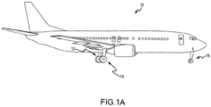
- an aircraft 10 is illustrated.
- the aircraft 10 includes landing gear, which may include a left main landing gear 12, a right main landing gear 14 and a nose landing gear 16.
- the landing gear support the aircraft 10 when it is not flying, allowing the aircraft 10 to taxi, take off and land without damage. While the disclosure refers to the three landing gear configurations just referred, the disclosure nevertheless contemplates any number of landing gear configurations.
- FIG. 1B there is schematically depicted a brake assembly or a brake mechanism 100 that may be used by the aircraft 10 of Figure 1A or any other appropriate aircraft.
- the brake mechanism 100 is mounted on an axle 102 for use with a wheel 104 disposed on and configured to rotate about the axle 102 via one or more bearing assemblies 103.
- the wheel 104 includes a hub 106, a wheel well 108 concentric about the hub 106 and a web portion 110 interconnecting the hub 106 and the wheel well 108.
- a central axis 112 extends through the axle 102 and defines a center of rotation of the wheel 104.
- a torque plate barrel 114 (sometimes referred to as a torque tube or barrel or a torque plate or back leg) is aligned concentrically with the hub 106, and the wheel 104 is rotatable relative to the torque plate barrel 114.
- the brake mechanism 100 includes a piston assembly 116, a pressure plate 118 disposed adjacent the piston assembly 116, an end plate 120 positioned a distal location from the piston assembly 116, and a plurality of rotor disks 122 interleaved with a plurality of stator disks 124 positioned intermediate the pressure plate 118 and the end plate 120.
- the pressure plate 118, the plurality of rotor disks 122, the plurality of stator disks 124 and the end plate 120 together form a brake heat sink or brake stack 126.
- the pressure plate 118, the end plate 120 and the plurality of stator disks 124 are mounted to the torque plate barrel 114 and remain rotationally stationary relative to the axle 102.
- Each stator disk 124 includes a pair of oppositely disposed sides 124a, 124b that each interface with a corresponding rotor disk 122 during a braking operation.
- the torque plate barrel 114 may include an annular barrel or torque tube 128 and an annular plate or back leg 130.
- the back leg 130 is disposed at an end distal from the piston assembly 116 and may be made monolithic with the torque tube 128, as illustrated in Figure 1B , or may be made as a separate annular piece and suitably connected to the torque tube 128.
- the torque tube 128 has a plurality of circumferentially spaced and axially extending splines 132 disposed on an outer surface of the torque tube 128.
- the plurality of stator disks 124 and the pressure plate 118 include notches or stator slots 134 on an inner periphery of the disks and the plate for engagement with the splines 132, such that each disk and the plate are axially slidable with respect to the torque tube 128.
- the end plate 120 is suitably connected to the back leg 130 of the torque plate barrel 114 and is held non-rotatable, together with the plurality of stator disks 124 and the pressure plate 118, during a braking action.
- An actuating mechanism for the brake mechanism 100 includes a plurality of piston assemblies, including the piston assembly 116, circumferentially spaced around an annular piston housing 156 (only one piston assembly is illustrated in Figure 1B ).
- the plurality of piston assemblies affect a braking action by urging the pressure plate 118 and the plurality of stator disks 124 into frictional engagement with the plurality of rotor disks 122 and against the end plate 120.
- Fluid or hydraulic pressure, mechanical springs or electric actuators, among other mechanisms, may be used to actuate the plurality of piston assemblies.
- the plurality of rotor disks 122 and the plurality of stator disks 124 are fabricated from various materials, such as, for example, carbon, carbon composites, and the like, that enable the brake disks to withstand and dissipate the heat generated during and following a braking action.
- the torque plate barrel 114 is secured to a stationary portion of the landing gear such as the axle 102, preventing the torque plate barrel 114 and the plurality of stator disks 124 from rotating during braking of the aircraft.
- the torque tube 128 portion of the torque plate barrel 114 may be attached to the annular piston housing 156 via an annular mounting surface 158, wherein bolt fasteners 160 secure the torque plate barrel 114 to the annular piston housing 156.
- a spacer member or pedestal 162 is positioned between an inner diameter surface 164 of the torque tube 128 and an outer diameter surface 166 of the axle 102.
- the pedestal 162 includes a radially inner surface or foot 168 for engaging the axle 102, a web portion 170 radially outward of the foot 168 and a head portion 172 for engaging the inner diameter surface 164 of the torque tube 128.
- the pedestal 162 augments support of the torque plate barrel 114 within the brake mechanism 100 generally and, more particularly, against the axle 102.
- the pedestal 162 may be made monolithic with the torque tube 128 portion of the torque plate barrel 114.
- a heat shield 140 is secured directly or indirectly to the wheel 104 between a radially inward surface of the wheel well 108 and the plurality of torque bars 138. As illustrated in Figure 1B , the heat shield 140 is concentric with the wheel well 108 and may have a plurality of heat shield sections 142 disposed between respective, adjacent pairs of the plurality of torque bars 138.
- the heat shield 140 is spaced from the radially inward surface of the wheel well 108 and secured in place by heat shield tabs 190, such that the heat shield 140, or heat shield sections 142, is disposed generally parallel to the axis of rotation or central axis 112 of the wheel 104 and intermediate the plurality of torque bars 138 and the radially inward surface of the wheel well 108.
- the heat shield 140, or heat shield sections 142 may be further secured in place by heat shield carriers 144.
- the plurality of torque bars 138 is attached at axially inboard ends to the wheel 104 by torque bar bolts 146.
- the torque bar bolts 146 extend through respective holes in a flange 150 provided on the wheel 104 as shown, which flange 150 for purposes of the present description is intended to be considered as part of the wheel well 108.
- Each of the plurality of torque bars 138 may include a pin 152 or similar member at its axially outboard end (i.e., the end opposite the torque bar bolts 146) that is received within a hole 154 disposed proximate the web portion 110 of the wheel 104.
- the heat shield 140, or heat shield sections 142 is positioned adjacent a radially inward surface of the wheel well 108 and secured in place by the heat shield tabs 190.
- FIG 2A illustrates a stator disk 220 that may be used as the stator disks 124 addressed above with regard to the brake assembly 100 of Figure 1B .
- the stator disk 220 may be formed from any appropriate material or combination of materials, the stator disk 220 may be formed from carbon in various embodiments.
- An inner perimeter 230 of the stator disk 220 (or more generally for an inner perimeter 230 of a stator disk assembly that utilizes the stator disk 220) is illustrated in Figure 2A , is annularly disposed about a first reference axis 260 (e.g., extends a full 360° about the axis 260), and defines an outer boundary of a first aperture or a first mounting aperture 226 (e.g., for receipt of a torque plate).
- a plurality of lugs 236 are incorporated by the inner perimeter 230, and these lugs 236 may be characterized as being disposed in radially-spaced or circumferentially-spaced relation to one another about/relative to the first reference axis 260.
- a recess 232 is disposed between each adjacent pair of lugs 236.
- the stator disk 220 also includes a plurality of recesses 232 and these recesses 232 may be characterized as being disposed in radially-spaced or circumferentially-spaced relation to one another about/relative the first reference axis 260.
- These lugs 236 and recesses 232 will be addressed in more detail below in relation to Figure 2B and Figures 3A-3B .
- the stator disk 220 may include any appropriate number of lugs 236 and recesses 232.
- the stator disk 220 includes a first side 222 (e.g., corresponding with the first side 124a of one of the stator disks 124 shown in Figure 1B ), where this first side 222 may interface with a rotor disk during a braking operation.
- the stator disk 220 includes an oppositely disposed second side 224 (e.g., corresponding with the second side 124b of one of the stator disks 124 shown in Figure 1B ), where this second side 224 may interface with a different rotor disk during a braking operation.
- the thickness of the stator disk 220 corresponds with the spacing between these two sides 222, 224.
- Each of the first side 222 and second side 224 of the stator disk 220 include what may be characterized as a braking surface 252 that extends from an inner braking surface boundary 254 to the outer perimeter 250 of the stator disk 220.
- Each braking surface 252 would engage a different corresponding rotor disk (e.g., rotor disk 122 - Figure 1B ) during a braking operation.
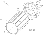
- FIG. 2B illustrates a portion of a brake assembly 200 (e.g., brake assembly 100 of Figure 1B ) that includes the above-described stator disk 220. Only an inward portion of the stator disk 220 (relative to the first reference axis 260) is illustrated in Figure 2B .
- the brake assembly 200 further includes a torque plate barrel or a torque plate 210.
- the torque plate barrel 210 includes an outer surface 212 that is disposed about the first reference axis 260. This outer surface 212 may be cylindrical.
- a plurality of splines, ribs, or protrusions 214 are disposed on the outer surface 212 of the torque plate barrel 210.
- the splines 214 may be disposed parallel with the first reference axis 260 and may be disposed about this same first reference axis 260 (e.g., the splines 214 may be characterized as being disposed in radially-spaced or circumferentially-spaced relation to one another about/relative the first reference axis 260).
- Each spline 214 of the torque plate barrel 210 is disposed in a corresponding recess 232 of the stator disk 220.
- the brake assembly will include an equal number of splines 214 (torque plate barrel 210) and recesses 232 (stator disk 220).
- stator disk 220 may be part of a stator disk assembly, which may comprise stator clips disposed within the recesses 232 of the stator disk 220.
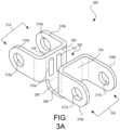
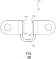
- FIGs. 3A and 3B illustrate a stator clip 300 according to the present invention
- Stator clips 300 may improve lug strength and the structural integrity of the stator disk.
- the stator clip 300 may comprise a spline interface 302.
- the spline interface 302 may include a first face 304 and a second face 306 opposite the first face 304.
- the spline interface 302 may comprise a third face 308 bridging between the first face 304 and the second face 306.
- the third face 308 may be substantially orthogonal to the first face 304 and the second face 306.
- the spline interface 302 may be U-shaped.
- the spline interface 302 may be a monolithic structure.
- the spline interface 302 of the stator clip 300 may be disposed in a corresponding recess 232 of the stator disk 220. Accordingly, each spline 214 of the torque plate barrel 210 may be disposed in the spline interface 302.
- the first face 304 and the second face 306 of the spline interface 302 may each comprise a ridge (e.g., raised pad).
- the spline interface 302 may comprise at least two ridges 310a/310b.
- Two ridges may be advantageous to provide increased loading stability, such that rotation is not dependent on a single ridge.
- the ridges 310a/310b may reduce the contact area between the torque plate barrel spline 214 and the stator clip 300, while maintaining the overall integrity of the stator clip 300. This may be advantageous since the greater the contact area between the spline and the stator clip, the greater the drag force.
- having the ridges 310a/310b along the first 304 and also having ridges 310a/310b along the second face 306 would orient the ridges perpendicular to the drag force (e.g., the direction of the drag), which may further reduce drag.
- the ridges 310a/310b may be hemi-cylindrical, extending longitudinally across the first face 304 and second face 306. Hemi-cylindrical ridges may be well suited to accommodate high torque, especially during high energy braking operations such as aircraft landing. However, the ridges 310a/310b may be of any desired shape suitable for accommodating torque load. In various embodiments, the ridges 310a/310b may be sized to accommodate the highest peak torque that may be generated by the brake assembly without damaging the brake assembly. In various embodiments, and as further shown in FIGs. 3A and 3B , the ridges 310a/310b may comprise rounded ends 312 or may be rounded to prevent edge loading that may contribute to dynamic instability. Accordingly, the ridges 310a/310b may reduce the likelihood of degraded braking performance or dynamic instability associated with edge loading.
- the stator clip 300 may comprise a first flange pair 314.
- the first flange pair 314 may be substantially orthogonal to a reverse side wall 316 of the first face 304.
- the first flange pair 314 may comprise opposing flanges 314a/314b.
- Each flange 314a/314b may define a lug recess 315a/315b.
- the stator clip 300 may further comprise a second flange pair 316.
- the second flange pair 316 may be substantially orthogonal to a reverse side wall 318 of the second face 306.
- the second flange pair 316 may comprise opposing flanges 316a/316b.
- Each flange 316a/316b may define a lug recess 317a/317b.
- the stator clip 300 may be riveted to a stator disk (e.g., FIG. 2B , 220) at the lug recesses 315a/315b/317a/317b of the flange pairs 314/316.
- Stator disk lugs FIG. 2A , 236) may be disposed within the lug recesses 315a/315b/317a/317b, securing the stator clip 300 to the stator disk ( FIG. 2B , 220).
- the flange pairs 314/316 may be substantially U-shaped, enabling the flanges to slide onto a stator disk.
- a method 400 of rearranging a brake assembly is illustrated in FIG. 4 .
- the method 400 may comprise removing (step 402) a first stator disk from the brake assembly.
- the method 400 may further comprise disposing (step 404) a stator clip in a recess of a second stator disk.
- a plurality of stator clips may be disposed in any number of recesses of the second stator disk.
- the method 400 may comprise reassembling (step 406) the brake assembly by disposing (step 408) the second stator disk on a torque plate barrel.
- the second stator disk may be disposed between an adjacent pair of rotor disks.
- references to "various embodiments”, “one embodiment”, “an embodiment”, “an example embodiment”, etc. indicate that the embodiment described may include a particular feature, structure, or characteristic, but every embodiment may not necessarily include the particular feature, structure, or characteristic. Moreover, such phrases are not necessarily referring to the same embodiment. Further, when a particular feature, structure, or characteristic is described in connection with an embodiment, it is submitted that it is within the knowledge of one skilled in the art to affect such feature, structure, or characteristic in connection with other embodiments whether or not explicitly described. After reading the description, it will be apparent to one skilled in the relevant art(s) how to implement the disclosure in alternative embodiments.
Landscapes
- Engineering & Computer Science (AREA)
- General Engineering & Computer Science (AREA)
- Mechanical Engineering (AREA)
- Aviation & Aerospace Engineering (AREA)
- Braking Arrangements (AREA)
Claims (10)
- Statorscheibenbaugruppe, umfassend:
eine Statorscheibe (220), die einen Innenumfang umfasst, der um eine erste Öffnung (226) angeordnet ist, wobei der Innenumfang Folgendes umfasst:eine erste Aussparung (232); undeinen ersten Ansatz (236) und einen zweiten Ansatz (236) in der Nähe der ersten Aussparung, wobei der erste Ansatz und der zweite Ansatz auf jeweils einer Seite der ersten Aussparung angeordnet sind; undeine erste Statorklammer (300), die innerhalb der ersten Aussparung angeordnet ist, wobei die erste Statorklammer eine Keilschnittstelle (302) umfasst, wobei die Keilschnittstelle Folgendes umfasst:eine erste Fläche (304);eine zweite Fläche (306), wobei die erste Fläche der zweiten Fläche gegenüberliegt, wobei die erste Fläche und die zweite Fläche jeweils eine Rippe umfassen; undeine dritte Fläche (308), die eine Brücke zwischen der ersten Fläche und der zweiten Fläche bildet, wobei die dritte Fläche orthogonal zu der ersten Fläche und zu der zweiten Fläche ist; ein erstes Flanschpaar (314), wobei das erste Flanschpaar orthogonal zu einer rückwärtigen Seitenwand (316) der ersten Fläche ist, wobei das erste Flanschpaar gegenüberliegende Flansche (314a, 314b) umfasst, wobei jeder Flansch eine Ansatzaussparung (315a, 315b) definiert; undein zweites Flanschpaar (316), wobei das zweite Flanschpaar orthogonal zu einer rückwärtigen Seitenwand (318) der zweiten Fläche ist, wobei das zweite Flanschpaar gegenüberliegende Flansche (316a, 316b) umfasst, wobei jeder Flansch eine Ansatzaussparung (317a, 317b) definiert, dadurch gekennzeichnet, dass die erste Fläche (304) und die zweite Fläche (306) jeweils mindestens zwei Rippen (310a, 310b) umfassen und wobei die mindestens zwei Rippen (310a, 310b) abgerundete Enden (312) umfassen, um eine Kantenbelastung zu verhindern, die zu einer dynamischen Instabilität beiträgt. - Statorscheibenbaugruppe nach Anspruch 1, wobei die Keilschnittstelle (302) der ersten Statorklammer (300) innerhalb der ersten Aussparung (232) angeordnet ist, wobei der erste Ansatz (236) innerhalb jeder Ansatzaussparung jedes Flansches (314a, 314b) des ersten Flanschpaars (314) angeordnet ist, wobei der zweite Ansatz (236) innerhalb jeder Ansatzaussparung (232) jedes Flansches (316a, 316b) des zweiten Flanschpaars (316) angeordnet ist, wobei die erste Statorklammer zum Nieten an die Statorscheibe (220) an dem ersten Flanschpaar und dem zweiten Flanschpaar konfiguriert ist.
- Statorscheibenbaugruppe nach Anspruch 2, wobei der Innenumfang ferner Folgendes umfasst:eine zweite Aussparung (232); undeinen dritten Ansatz (236) und einen vierten Ansatz (236) in der Nähe der zweiten Aussparung, wobei der dritte Ansatz und der vierte Ansatz auf jeweils einer Seite der zweiten Aussparung angeordnet sind; undeine zweite Statorklammer (300), die innerhalb der zweiten Aussparung angeordnet ist.
- Statorscheibenbaugruppe nach Anspruch 1, 2 oder 3, wobei die Keilschnittstelle (302) U-förmig ist; und/oder wobei die Keilschnittstelle monolithisch ist; und/oder wobei die Statorklammer (300) zum Nieten an eine Statorscheibe konfiguriert ist.
- Statorscheibenbaugruppe nach Anspruch 1, 2, 3 oder 4, wobei die mindestens zwei Rippen (310a, 310b) halbzylindrisch sind.
- Bremsbaugruppe, umfassend:einen Drehmomentplattenzylinder (210), der eine äußere Oberfläche (212) umfasst, die um eine erste Referenzachse (260) angeordnet ist, wobei die äußere Oberfläche einen ersten Keil (214) umfasst, der um die erste Referenzachse verläuft; und die Statorscheibenbaugruppe nach Anspruch 1, die auf dem Drehmomentplattenzylinder montiert ist, wobei sich der Drehmomentplattenzylinder in die erste Öffnung der Statorscheibe erstreckt; undwobei der erste Keil innerhalb einer Keilschnittstelle (302) der ersten Statorklemme angeordnet ist.
- Bremsbaugruppe nach Anspruch 6, wobei der Drehmomentplattenzylinder (210) ferner einen zweiten Keil (214) umfasst, wobei der zweite Keil und der erste Keil (214) um die erste Referenzachse (260) voneinander beabstandet sind.
- Bremsbaugruppe nach Anspruch 6 oder 7, wobei der Innenumfang ferner eine zweite Aussparung (232) umfasst, wobei der Innenumfang einen dritten Ansatz (236) und einen vierten Ansatz (236) in der Nähe der zweiten Aussparung umfasst, wobei der dritte Ansatz und der vierte Ansatz auf jeweils einer Seite der zweiten Aussparung angeordnet sind.
- Bremsbaugruppe nach Anspruch 8, ferner umfassend eine zweite Statorklammer (300), die in der zweiten Aussparung (232) angeordnet ist; und wobei der zweite Keil (214) gegebenenfalls in einer Keilschnittstelle (302) der zweiten Statorklammer (300) angeordnet ist; und wobei die erste Statorklammer (300) gegebenenfalls an den ersten Ansatz (236) und den zweiten Ansatz (236) des Innenumfangs genietet ist.
- Bremsbaugruppe nach Anspruch 9, wobei die zweite Statorklammer (300) an den dritten Ansatz (236) und den vierten Ansatz (236) des Innenumfangs genietet ist.
Applications Claiming Priority (1)
| Application Number | Priority Date | Filing Date | Title |
|---|---|---|---|
| US17/752,686 US12264717B2 (en) | 2022-05-24 | 2022-05-24 | Reduced drag stator clip |
Publications (2)
| Publication Number | Publication Date |
|---|---|
| EP4283153A1 EP4283153A1 (de) | 2023-11-29 |
| EP4283153B1 true EP4283153B1 (de) | 2024-12-18 |
Family
ID=86497614
Family Applications (1)
| Application Number | Title | Priority Date | Filing Date |
|---|---|---|---|
| EP23174950.8A Active EP4283153B1 (de) | 2022-05-24 | 2023-05-23 | Statorklammer mit verringertem widerstand |
Country Status (2)
| Country | Link |
|---|---|
| US (1) | US12264717B2 (de) |
| EP (1) | EP4283153B1 (de) |
Families Citing this family (2)
| Publication number | Priority date | Publication date | Assignee | Title |
|---|---|---|---|---|
| EP4293246B1 (de) * | 2022-06-13 | 2025-02-19 | Goodrich Corporation | Rotorclip für bremsenanordnung |
| FR3163417A1 (fr) * | 2024-06-13 | 2025-12-19 | Safran Ceramics | Disque de frein destine a une roue de vehicule |
Family Cites Families (9)
| Publication number | Priority date | Publication date | Assignee | Title |
|---|---|---|---|---|
| US3605967A (en) | 1969-04-07 | 1971-09-20 | Goodrich Co B F | Protective bearing member for brake or clutch |
| US3927740A (en) * | 1974-07-01 | 1975-12-23 | Goodyear Aerospace Corp | Brake disk with tapered key way |
| US4007814A (en) * | 1976-02-05 | 1977-02-15 | Goodyear Aerospace Corporation | Carbon brake disk with cast keyslot reinforcement members |
| AU4995179A (en) * | 1978-09-25 | 1980-04-03 | B.F. Goodrich Company, The | Disc brake assembly containing split discs |
| US4585096A (en) | 1984-08-03 | 1986-04-29 | The B. F. Goodrich Company | Brake apparatus |
| US4784246A (en) * | 1987-02-18 | 1988-11-15 | The B. F. Goodrich Company | Brake apparatus |
| JP5791487B2 (ja) * | 2011-12-16 | 2015-10-07 | 曙ブレーキ工業株式会社 | 複合型ディスクロータ |
| US10436265B2 (en) | 2017-08-10 | 2019-10-08 | Goodrich Corporation | Rivet-less rotor clip design |
| US11346416B2 (en) | 2020-04-23 | 2022-05-31 | Honeywell International Inc. | Brake disc insert with bridge member |
-
2022
- 2022-05-24 US US17/752,686 patent/US12264717B2/en active Active
-
2023
- 2023-05-23 EP EP23174950.8A patent/EP4283153B1/de active Active
Also Published As
| Publication number | Publication date |
|---|---|
| US12264717B2 (en) | 2025-04-01 |
| EP4283153A1 (de) | 2023-11-29 |
| US20230383800A1 (en) | 2023-11-30 |
Similar Documents
| Publication | Publication Date | Title |
|---|---|---|
| EP3480072B1 (de) | Abschirmungsanbringungsvorrichtung | |
| EP3670955B1 (de) | Hitzeschildhalterung und verfahren | |
| EP3767125B1 (de) | Hitzeschildhalterung und verfahren | |
| EP4283153B1 (de) | Statorklammer mit verringertem widerstand | |
| EP3647622B1 (de) | Segmentierter hitzeschild mit reduzierter zwischenschichtwärmeleitung | |
| EP4283154B1 (de) | Statorklammer für bremsanordnung | |
| EP3726087B1 (de) | Mehrschichtiger kolbenisolator für hydraulischen bremszylinder | |
| EP3524517B1 (de) | Isolierte drehmomentplattenfussanordnung | |
| EP4209691B1 (de) | Gegabelte hitzeschildbefestigungsklammer | |
| US12331801B2 (en) | Stator clip for brake assembly | |
| EP4414581B1 (de) | Verwendung von profilierter reaktionsfläche bei hybriden drehmomentstangenanwendungen | |
| US12454350B2 (en) | Tapered torque plate barrel for improving dynamic stability | |
| US12545397B2 (en) | Heat shield retaining clasp | |
| EP4289689B1 (de) | Mehrschichtiger flugzeugbremsisolator | |
| EP4219974A2 (de) | Hitzeschildanordnung mit versteifungsplatte |
Legal Events
| Date | Code | Title | Description |
|---|---|---|---|
| PUAI | Public reference made under article 153(3) epc to a published international application that has entered the european phase |
Free format text: ORIGINAL CODE: 0009012 |
|
| STAA | Information on the status of an ep patent application or granted ep patent |
Free format text: STATUS: THE APPLICATION HAS BEEN PUBLISHED |
|
| AK | Designated contracting states |
Kind code of ref document: A1 Designated state(s): AL AT BE BG CH CY CZ DE DK EE ES FI FR GB GR HR HU IE IS IT LI LT LU LV MC ME MK MT NL NO PL PT RO RS SE SI SK SM TR |
|
| STAA | Information on the status of an ep patent application or granted ep patent |
Free format text: STATUS: REQUEST FOR EXAMINATION WAS MADE |
|
| 17P | Request for examination filed |
Effective date: 20240527 |
|
| RBV | Designated contracting states (corrected) |
Designated state(s): AL AT BE BG CH CY CZ DE DK EE ES FI FR GB GR HR HU IE IS IT LI LT LU LV MC ME MK MT NL NO PL PT RO RS SE SI SK SM TR |
|
| GRAP | Despatch of communication of intention to grant a patent |
Free format text: ORIGINAL CODE: EPIDOSNIGR1 |
|
| STAA | Information on the status of an ep patent application or granted ep patent |
Free format text: STATUS: GRANT OF PATENT IS INTENDED |
|
| RIC1 | Information provided on ipc code assigned before grant |
Ipc: F16D 65/12 20060101ALI20240619BHEP Ipc: F16D 55/40 20060101AFI20240619BHEP |
|
| INTG | Intention to grant announced |
Effective date: 20240719 |
|
| RIN1 | Information on inventor provided before grant (corrected) |
Inventor name: O'NEIL, MATHEW R. Inventor name: BONIFAS, ALAN M. |
|
| RIN1 | Information on inventor provided before grant (corrected) |
Inventor name: BONIFAS, ALAN M. Inventor name: O'NEIL, MATTHEW R. |
|
| GRAS | Grant fee paid |
Free format text: ORIGINAL CODE: EPIDOSNIGR3 |
|
| GRAA | (expected) grant |
Free format text: ORIGINAL CODE: 0009210 |
|
| STAA | Information on the status of an ep patent application or granted ep patent |
Free format text: STATUS: THE PATENT HAS BEEN GRANTED |
|
| AK | Designated contracting states |
Kind code of ref document: B1 Designated state(s): AL AT BE BG CH CY CZ DE DK EE ES FI FR GB GR HR HU IE IS IT LI LT LU LV MC ME MK MT NL NO PL PT RO RS SE SI SK SM TR |
|
| REG | Reference to a national code |
Ref country code: CH Ref legal event code: EP |
|
| REG | Reference to a national code |
Ref country code: DE Ref legal event code: R096 Ref document number: 602023001393 Country of ref document: DE |
|
| REG | Reference to a national code |
Ref country code: IE Ref legal event code: FG4D |
|
| REG | Reference to a national code |
Ref country code: LT Ref legal event code: MG9D |
|
| PG25 | Lapsed in a contracting state [announced via postgrant information from national office to epo] |
Ref country code: HR Free format text: LAPSE BECAUSE OF FAILURE TO SUBMIT A TRANSLATION OF THE DESCRIPTION OR TO PAY THE FEE WITHIN THE PRESCRIBED TIME-LIMIT Effective date: 20241218 |
|
| PG25 | Lapsed in a contracting state [announced via postgrant information from national office to epo] |
Ref country code: FI Free format text: LAPSE BECAUSE OF FAILURE TO SUBMIT A TRANSLATION OF THE DESCRIPTION OR TO PAY THE FEE WITHIN THE PRESCRIBED TIME-LIMIT Effective date: 20241218 |
|
| PG25 | Lapsed in a contracting state [announced via postgrant information from national office to epo] |
Ref country code: BG Free format text: LAPSE BECAUSE OF FAILURE TO SUBMIT A TRANSLATION OF THE DESCRIPTION OR TO PAY THE FEE WITHIN THE PRESCRIBED TIME-LIMIT Effective date: 20241218 |
|
| PG25 | Lapsed in a contracting state [announced via postgrant information from national office to epo] |
Ref country code: NO Free format text: LAPSE BECAUSE OF FAILURE TO SUBMIT A TRANSLATION OF THE DESCRIPTION OR TO PAY THE FEE WITHIN THE PRESCRIBED TIME-LIMIT Effective date: 20250318 |
|
| REG | Reference to a national code |
Ref country code: NL Ref legal event code: MP Effective date: 20241218 |
|
| PG25 | Lapsed in a contracting state [announced via postgrant information from national office to epo] |
Ref country code: LV Free format text: LAPSE BECAUSE OF FAILURE TO SUBMIT A TRANSLATION OF THE DESCRIPTION OR TO PAY THE FEE WITHIN THE PRESCRIBED TIME-LIMIT Effective date: 20241218 Ref country code: GR Free format text: LAPSE BECAUSE OF FAILURE TO SUBMIT A TRANSLATION OF THE DESCRIPTION OR TO PAY THE FEE WITHIN THE PRESCRIBED TIME-LIMIT Effective date: 20250319 |
|
| PG25 | Lapsed in a contracting state [announced via postgrant information from national office to epo] |
Ref country code: RS Free format text: LAPSE BECAUSE OF FAILURE TO SUBMIT A TRANSLATION OF THE DESCRIPTION OR TO PAY THE FEE WITHIN THE PRESCRIBED TIME-LIMIT Effective date: 20250318 |
|
| PG25 | Lapsed in a contracting state [announced via postgrant information from national office to epo] |
Ref country code: NL Free format text: LAPSE BECAUSE OF FAILURE TO SUBMIT A TRANSLATION OF THE DESCRIPTION OR TO PAY THE FEE WITHIN THE PRESCRIBED TIME-LIMIT Effective date: 20241218 |
|
| REG | Reference to a national code |
Ref country code: AT Ref legal event code: MK05 Ref document number: 1752441 Country of ref document: AT Kind code of ref document: T Effective date: 20241218 |
|
| PG25 | Lapsed in a contracting state [announced via postgrant information from national office to epo] |
Ref country code: SM Free format text: LAPSE BECAUSE OF FAILURE TO SUBMIT A TRANSLATION OF THE DESCRIPTION OR TO PAY THE FEE WITHIN THE PRESCRIBED TIME-LIMIT Effective date: 20241218 |
|
| PG25 | Lapsed in a contracting state [announced via postgrant information from national office to epo] |
Ref country code: PL Free format text: LAPSE BECAUSE OF FAILURE TO SUBMIT A TRANSLATION OF THE DESCRIPTION OR TO PAY THE FEE WITHIN THE PRESCRIBED TIME-LIMIT Effective date: 20241218 |
|
| PG25 | Lapsed in a contracting state [announced via postgrant information from national office to epo] |
Ref country code: ES Free format text: LAPSE BECAUSE OF FAILURE TO SUBMIT A TRANSLATION OF THE DESCRIPTION OR TO PAY THE FEE WITHIN THE PRESCRIBED TIME-LIMIT Effective date: 20241218 |
|
| PG25 | Lapsed in a contracting state [announced via postgrant information from national office to epo] |
Ref country code: IS Free format text: LAPSE BECAUSE OF FAILURE TO SUBMIT A TRANSLATION OF THE DESCRIPTION OR TO PAY THE FEE WITHIN THE PRESCRIBED TIME-LIMIT Effective date: 20250418 |
|
| PG25 | Lapsed in a contracting state [announced via postgrant information from national office to epo] |
Ref country code: PT Free format text: LAPSE BECAUSE OF FAILURE TO SUBMIT A TRANSLATION OF THE DESCRIPTION OR TO PAY THE FEE WITHIN THE PRESCRIBED TIME-LIMIT Effective date: 20250421 |
|
| PG25 | Lapsed in a contracting state [announced via postgrant information from national office to epo] |
Ref country code: EE Free format text: LAPSE BECAUSE OF FAILURE TO SUBMIT A TRANSLATION OF THE DESCRIPTION OR TO PAY THE FEE WITHIN THE PRESCRIBED TIME-LIMIT Effective date: 20241218 |
|
| PGFP | Annual fee paid to national office [announced via postgrant information from national office to epo] |
Ref country code: FR Payment date: 20250423 Year of fee payment: 3 |
|
| PG25 | Lapsed in a contracting state [announced via postgrant information from national office to epo] |
Ref country code: AT Free format text: LAPSE BECAUSE OF FAILURE TO SUBMIT A TRANSLATION OF THE DESCRIPTION OR TO PAY THE FEE WITHIN THE PRESCRIBED TIME-LIMIT Effective date: 20241218 Ref country code: RO Free format text: LAPSE BECAUSE OF FAILURE TO SUBMIT A TRANSLATION OF THE DESCRIPTION OR TO PAY THE FEE WITHIN THE PRESCRIBED TIME-LIMIT Effective date: 20241218 |
|
| PG25 | Lapsed in a contracting state [announced via postgrant information from national office to epo] |
Ref country code: SK Free format text: LAPSE BECAUSE OF FAILURE TO SUBMIT A TRANSLATION OF THE DESCRIPTION OR TO PAY THE FEE WITHIN THE PRESCRIBED TIME-LIMIT Effective date: 20241218 |
|
| PG25 | Lapsed in a contracting state [announced via postgrant information from national office to epo] |
Ref country code: CZ Free format text: LAPSE BECAUSE OF FAILURE TO SUBMIT A TRANSLATION OF THE DESCRIPTION OR TO PAY THE FEE WITHIN THE PRESCRIBED TIME-LIMIT Effective date: 20241218 |
|
| PG25 | Lapsed in a contracting state [announced via postgrant information from national office to epo] |
Ref country code: IT Free format text: LAPSE BECAUSE OF FAILURE TO SUBMIT A TRANSLATION OF THE DESCRIPTION OR TO PAY THE FEE WITHIN THE PRESCRIBED TIME-LIMIT Effective date: 20241218 |
|
| PG25 | Lapsed in a contracting state [announced via postgrant information from national office to epo] |
Ref country code: SE Free format text: LAPSE BECAUSE OF FAILURE TO SUBMIT A TRANSLATION OF THE DESCRIPTION OR TO PAY THE FEE WITHIN THE PRESCRIBED TIME-LIMIT Effective date: 20241218 |
|
| REG | Reference to a national code |
Ref country code: DE Ref legal event code: R097 Ref document number: 602023001393 Country of ref document: DE |
|
| PG25 | Lapsed in a contracting state [announced via postgrant information from national office to epo] |
Ref country code: DK Free format text: LAPSE BECAUSE OF FAILURE TO SUBMIT A TRANSLATION OF THE DESCRIPTION OR TO PAY THE FEE WITHIN THE PRESCRIBED TIME-LIMIT Effective date: 20241218 |
|
| PLBE | No opposition filed within time limit |
Free format text: ORIGINAL CODE: 0009261 |
|
| STAA | Information on the status of an ep patent application or granted ep patent |
Free format text: STATUS: NO OPPOSITION FILED WITHIN TIME LIMIT |
|
| 26N | No opposition filed |
Effective date: 20250919 |
|
| REG | Reference to a national code |
Ref country code: DE Ref legal event code: R119 Ref document number: 602023001393 Country of ref document: DE |
|
| PG25 | Lapsed in a contracting state [announced via postgrant information from national office to epo] |
Ref country code: LU Free format text: LAPSE BECAUSE OF NON-PAYMENT OF DUE FEES Effective date: 20250523 |
|
| REG | Reference to a national code |
Ref country code: BE Ref legal event code: MM Effective date: 20250531 |
|
| PG25 | Lapsed in a contracting state [announced via postgrant information from national office to epo] |
Ref country code: MC Free format text: LAPSE BECAUSE OF FAILURE TO SUBMIT A TRANSLATION OF THE DESCRIPTION OR TO PAY THE FEE WITHIN THE PRESCRIBED TIME-LIMIT Effective date: 20241218 |
|
| PG25 | Lapsed in a contracting state [announced via postgrant information from national office to epo] |
Ref country code: DE Free format text: LAPSE BECAUSE OF NON-PAYMENT OF DUE FEES Effective date: 20251202 Ref country code: IE Free format text: LAPSE BECAUSE OF NON-PAYMENT OF DUE FEES Effective date: 20250523 |
|
| PG25 | Lapsed in a contracting state [announced via postgrant information from national office to epo] |
Ref country code: BE Free format text: LAPSE BECAUSE OF NON-PAYMENT OF DUE FEES Effective date: 20250531 |