EP4283151A1 - Système d'actionnement d'embrayage à chambres multiples et à multiplicateur de force pour prise de force - Google Patents
Système d'actionnement d'embrayage à chambres multiples et à multiplicateur de force pour prise de force Download PDFInfo
- Publication number
- EP4283151A1 EP4283151A1 EP23175127.2A EP23175127A EP4283151A1 EP 4283151 A1 EP4283151 A1 EP 4283151A1 EP 23175127 A EP23175127 A EP 23175127A EP 4283151 A1 EP4283151 A1 EP 4283151A1
- Authority
- EP
- European Patent Office
- Prior art keywords
- clutch
- power take
- primary
- piston
- cylinder
- Prior art date
- Legal status (The legal status is an assumption and is not a legal conclusion. Google has not performed a legal analysis and makes no representation as to the accuracy of the status listed.)
- Pending
Links
- 230000007246 mechanism Effects 0.000 claims abstract description 26
- 239000012530 fluid Substances 0.000 claims description 21
- 230000005540 biological transmission Effects 0.000 description 9
- 239000000463 material Substances 0.000 description 2
- 230000007812 deficiency Effects 0.000 description 1
- 230000003467 diminishing effect Effects 0.000 description 1
- 239000007788 liquid Substances 0.000 description 1
- 239000010813 municipal solid waste Substances 0.000 description 1
Images

Classifications
-
- B—PERFORMING OPERATIONS; TRANSPORTING
- B60—VEHICLES IN GENERAL
- B60K—ARRANGEMENT OR MOUNTING OF PROPULSION UNITS OR OF TRANSMISSIONS IN VEHICLES; ARRANGEMENT OR MOUNTING OF PLURAL DIVERSE PRIME-MOVERS IN VEHICLES; AUXILIARY DRIVES FOR VEHICLES; INSTRUMENTATION OR DASHBOARDS FOR VEHICLES; ARRANGEMENTS IN CONNECTION WITH COOLING, AIR INTAKE, GAS EXHAUST OR FUEL SUPPLY OF PROPULSION UNITS IN VEHICLES
- B60K17/00—Arrangement or mounting of transmissions in vehicles
- B60K17/28—Arrangement or mounting of transmissions in vehicles characterised by arrangement, location, or type of power take-off
-
- F—MECHANICAL ENGINEERING; LIGHTING; HEATING; WEAPONS; BLASTING
- F16—ENGINEERING ELEMENTS AND UNITS; GENERAL MEASURES FOR PRODUCING AND MAINTAINING EFFECTIVE FUNCTIONING OF MACHINES OR INSTALLATIONS; THERMAL INSULATION IN GENERAL
- F16D—COUPLINGS FOR TRANSMITTING ROTATION; CLUTCHES; BRAKES
- F16D25/00—Fluid-actuated clutches
- F16D25/06—Fluid-actuated clutches in which the fluid actuates a piston incorporated in, i.e. rotating with the clutch
- F16D25/062—Fluid-actuated clutches in which the fluid actuates a piston incorporated in, i.e. rotating with the clutch the clutch having friction surfaces
- F16D25/063—Fluid-actuated clutches in which the fluid actuates a piston incorporated in, i.e. rotating with the clutch the clutch having friction surfaces with clutch members exclusively moving axially
- F16D25/0635—Fluid-actuated clutches in which the fluid actuates a piston incorporated in, i.e. rotating with the clutch the clutch having friction surfaces with clutch members exclusively moving axially with flat friction surfaces, e.g. discs
- F16D25/0638—Fluid-actuated clutches in which the fluid actuates a piston incorporated in, i.e. rotating with the clutch the clutch having friction surfaces with clutch members exclusively moving axially with flat friction surfaces, e.g. discs with more than two discs, e.g. multiple lamellae
-
- F—MECHANICAL ENGINEERING; LIGHTING; HEATING; WEAPONS; BLASTING
- F16—ENGINEERING ELEMENTS AND UNITS; GENERAL MEASURES FOR PRODUCING AND MAINTAINING EFFECTIVE FUNCTIONING OF MACHINES OR INSTALLATIONS; THERMAL INSULATION IN GENERAL
- F16D—COUPLINGS FOR TRANSMITTING ROTATION; CLUTCHES; BRAKES
- F16D13/00—Friction clutches
- F16D13/22—Friction clutches with axially-movable clutching members
- F16D13/38—Friction clutches with axially-movable clutching members with flat clutching surfaces, e.g. discs
- F16D13/52—Clutches with multiple lamellae ; Clutches in which three or more axially moveable members are fixed alternately to the shafts to be coupled and are pressed from one side towards an axially-located member
- F16D13/54—Clutches with multiple lamellae ; Clutches in which three or more axially moveable members are fixed alternately to the shafts to be coupled and are pressed from one side towards an axially-located member with means for increasing the effective force between the actuating sleeve or equivalent member and the pressure member
-
- F—MECHANICAL ENGINEERING; LIGHTING; HEATING; WEAPONS; BLASTING
- F16—ENGINEERING ELEMENTS AND UNITS; GENERAL MEASURES FOR PRODUCING AND MAINTAINING EFFECTIVE FUNCTIONING OF MACHINES OR INSTALLATIONS; THERMAL INSULATION IN GENERAL
- F16D—COUPLINGS FOR TRANSMITTING ROTATION; CLUTCHES; BRAKES
- F16D2127/00—Auxiliary mechanisms
- F16D2127/02—Release mechanisms
-
- F—MECHANICAL ENGINEERING; LIGHTING; HEATING; WEAPONS; BLASTING
- F16—ENGINEERING ELEMENTS AND UNITS; GENERAL MEASURES FOR PRODUCING AND MAINTAINING EFFECTIVE FUNCTIONING OF MACHINES OR INSTALLATIONS; THERMAL INSULATION IN GENERAL
- F16D—COUPLINGS FOR TRANSMITTING ROTATION; CLUTCHES; BRAKES
- F16D2300/00—Special features for couplings or clutches
- F16D2300/14—Clutches which are normally open, i.e. not engaged in released state
Definitions
- This invention relates in general to power take-offs for transmitting rotational energy from a source of rotational energy to a rotatably driven accessory.
- this invention relates to an improved structure for such a power take-off that includes a force intensifying, multi-chambered, clutch actuator.
- a power take-off is a well-known mechanical device that is often used in conjunction with a source of rotational energy, such as a vehicle engine or transmission, to transfer rotational energy to a rotatably driven accessory, such as a hydraulic pump that is supported on the vehicle.
- a source of rotational energy such as a vehicle engine or transmission
- a rotatably driven accessory such as a hydraulic pump that is supported on the vehicle.
- power take-offs are commonly used on industrial and agricultural vehicles to transfer rotational energy from the vehicle engine or transmission to one or more hydraulic pumps that, in turn, are used to operate one or more hydraulically driven accessories provided on the vehicle, such as plows, trash compactors, lifting mechanisms, winches, and the like.
- the power take-off provides a simple, inexpensive, and convenient means for transferring energy from the source of rotational energy to the hydraulic pump that, in turn, can be operated to transfer relatively high pressure fluid to operate the driven accessory.
- a typical power take-off includes a housing, an input mechanism, and an output mechanism.
- the power take-off housing is adapted to be supported on a housing of the source of rotational energy.
- the power take-off housing includes an opening that is aligned with a corresponding opening provided in the housing of the source of rotational energy.
- the input mechanism of the power take-off includes a portion (typically a spur gear) that extends outwardly from the power take-off housing through the aligned openings and into the housing of the source of rotational energy. In this manner, the input mechanism of the power take-off is connected to the source of rotational energy so as to be rotatably driven whenever the source of rotational energy is operated.
- the output mechanism of the power take-off is rotatably driven by the input mechanism and is adapted to be connected to the rotatably driven accessory.
- the input mechanism of the power take-off is directly connected to the output mechanism such that the rotatably driven accessory is operated whenever the source of rotational energy is operated.
- a clutch assembly is provided between the input mechanism and the output mechanism such that the rotatably driven accessory is operated only when the clutch assembly is engaged while the source of rotational energy is operated.
- the power take-off may be designed to allow the clutch assembly to be safely engaged and/or disengaged at any time without any decoupling gears within the power take-off gear train (including when the power take-off is being rotatably driven by the source of rotational energy and, therefore, while torque is being transmitted through the power take-off).
- Such power take-offs (often referred to as hotshift power take-offs) utilize pressurized fluid from the transmission to actuate the clutch assembly, which permits the output shaft of the power take-off to be decoupled from the rotation of the rotatably driven transmission.
- the amount of engagement force that can be exerted by the clutch assembly of the power take-off is directly related to the amount of torque that can be transmitted through the power take-off when it is engaged. Because the size of the clutch assembly is generally related to the amount of this engagement force, the maximum amount of such engagement force is, at least in some instances, limited by the amount of physical space that is available in the vicinity of the vehicle where the power take-off is located.
- This invention relates to an improved structure for a power take-off that includes a force intensifying, multi-chambered, clutch actuator that provides additional torque capacity, but does not require a significant additional amount of physical space in the vicinity of the vehicle where the power take-off is located.
- the power take-off of this invention includes a multiple-chambered clutch system that permits the amount of the engagement force that is generated by the clutch to be increased, without increasing the line pressure from the transmission or the overall diameter of the physical size of the clutch system. This results in additional power density in the clutch and, ultimately, more power-dense solutions and increased-torque capacities.
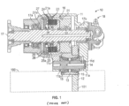
- Fig. 1 a sectional elevational view of a power take-off, indicated generally at 10, in accordance with this invention.
- the basic structure and mode of operation of the power take-off 10 are well known in the art, and only those portions of the power take-off 10 that are necessary for a complete understanding of the invention will be described.
- the illustrated power take-off 10 is intended merely to illustrate one environment in which this invention may be used.
- the scope of this invention is not intended to be limited for use with the specific structure of the power take-off 10 illustrated in Fig. 1 or with power take-offs in general.
- this invention may be used in any desired environment for the purposes described below.
- the illustrated power take-off 10 includes a hollow housing 11 having a mounting surface 11a provided thereon. An opening 11b is provided through the mounting surface 11a of the power take-off housing 11.
- the power take-off 10 has an input mechanism that includes an input gear 12 that is rotatably supported within the power take-off housing 11. As shown in Fig. 1 , a portion of the input gear 12 extends outwardly through the opening 11b provided through the mounting surface 11a.
- the mounting surface 11a of the power take-off housing 11 is adapted to be secured (typically by a plurality of bolts - not shown) to a corresponding mounting surface provided on a housing of a source of rotational energy 100, such as an engine or a transmission of a vehicle.
- a source of rotational energy 100 such as an engine or a transmission of a vehicle.
- the portion of the input gear 12 that extends through the opening 11b of the power take-off housing 11 also extends through a corresponding opening (not shown) provided in the housing of the source of rotational energy 100 into engagement with a driving gear 101 or other mechanism provided therein.
- the input gear 12 of the power take-off 10 is rotatably driven whenever the driving gear 101 contained within the source of rotational energy 100 is rotatably driven.
- the illustrated input gear 12 is splined onto or otherwise supported on an input gear hub 13 for concurrent rotation to form a conventional input cluster gear.
- the input gear hub 13 is, in turn, rotatably supported on an input shaft 14 by one or more bearings 15.
- First and second ends of the illustrated input shaft 14 are respectively (and typically non-rotatably) supported in first and second bores 11c and 11d provided in the power take-off housing 11.
- the power take-off 10 also includes a clutch assembly, indicated generally at 16, for selectively connecting the input gear hub 13 (and, thus, the input gear 12 supported thereon) to an output shaft 17.
- the output shaft 17 is, in turn, adapted to be connected to the rotatably driven accessory (not shown).
- the illustrated output shaft 17 is rotatably supported on the power take-off housing 11 by a pair of bearings 17a and 17b or other similar means.
- the clutch assembly 16 When the clutch assembly 16 is engaged, the input gear hub 13 is connected to the output shaft 17 for concurrent rotation.
- the rotatably driven accessory is rotatably driven by the source of rotational power when the clutch assembly 16 is engaged.
- the clutch assembly 16 Conversely, when the clutch assembly 16 is disengaged, the input gear hub 13 is disconnected from the output shaft 17.
- a conventional shifter assembly indicated generally at 18, may be provided to selectively engage and disengage the clutch assembly 16 in a known manner.
- the clutch assembly 16 of the power take-off 10 includes a drive gear 21 that is rotatably supported on the output shaft 17 by a bearing 22 and is rotatably driven by the input gear hub 13.
- the illustrated drive gear 21 includes an axially-extending hollow cylindrical bell portion 21a having a splined inner surface.
- the illustrated drive gear 21 is formed integrally from a single piece of material with the hollow cylindrical bell portion 21a.
- a plurality of flat annular clutch plates 23 is splined to the inner splined surface of the hollow cylindrical bell portion 21a of the drive gear 21 for rotation therewith.
- the drive gear 21 and the clutch plates 23 are constantly rotatably driven by the input gear 12.
- a plurality of annular friction plates 24 is disposed in an alternating fashion between the clutch plates 23.
- the friction plates 24 are splined to an outer splined surface provided on an axially extending cylindrical portion 25a of a clutch gear 25 for rotation therewith.
- the clutch gear 25 is splined or otherwise secured to the output shaft 17 for rotation therewith.
- the clutch gear 25 is restrained from axial movement in one direction (toward the right when viewing Fig. 1 ) by one or more retaining rings 25b that are mounted on the output shaft 17, for a purpose that will be explained below.
- An annular clutch piston 26 is provided for selectively causing the clutch plates 23 and the friction plates 24 to frictionally engage one another so as to engage the clutch assembly 16.
- the clutch piston 26 is disposed within a hollow cylindrical clutch cylinder 27.
- the clutch cylinder 27 has a closed end and an opened end.
- One end of the clutch piston 26 (the left end when viewing Fig. 1 ) is disposed within the clutch cylinder 27, while the opposite end of the clutch piston 26 (the right end when viewing Fig. 1 ) extends from the opened end of the clutch cylinder 27 adjacent to the interleaved set of clutch plates 23 and friction plates 24.
- Both the clutch piston 26 and the clutch cylinder 27 are supported on the output shaft 17.
- the clutch piston 26 is axially movable along the output shaft 17, but the clutch cylinder 27 is restrained from axial movement in one direction (toward the left when viewing Fig. 1 ) by one or more retaining rings 27a that are mounted on the output shaft 17 for a purpose that will be explained below.
- a coiled clutch spring 28 reacts between the clutch piston 26 and the clutch gear 25.
- the clutch gear 25 is restrained from axial movement in one direction (toward the right when viewing Fig. 1 ) by the retaining ring 25b.
- the clutch spring 28 urges the clutch piston 26 axially in the opposite direction (toward the left when viewing Fig. 1 ) toward a disengaged position adjacent to the closed end of the clutch cylinder 27.
- the clutch piston 26 In the disengaged position, the clutch piston 26 does not engage the clutch plates 23 or the friction plates 24.
- the clutch plates 23 and the friction plates 24 do not frictionally engage one another.
- the clutch gear 25 is disconnected from the drive gear 21 so as to provide no rotatable driving connection therebetween.
- the shifter assembly 18 is actuated to supply pressurized fluid to an annular clutch chamber 29 defined between the clutch piston 26 and the closed end of the clutch cylinder 27.
- the clutch piston 26 is moved axially in the one direction (toward the right when viewing Fig. 1 ) toward an engaged position.
- the clutch piston 26 causes the clutch plates 23 and the friction plates 24 to frictionally engage one another.
- the clutch gear 25 is connected to the drive gear 21 so as to provide a rotatable driving connection therebetween.
- Fig. 2 is an enlarged sectional elevational view of a modified portion of the conventional power take-off 10 illustrated in Fig. 1 that includes a force intensifying, multi-chambered, clutch actuator, indicated generally at 200, in accordance with this invention.
- the illustrated clutch actuator 200 of this invention includes a primary clutch cylinder 201 that is supported on the output shaft 17 of the power take-off 10.
- the primary clutch cylinder 201 is preferably restrained from axial movement relative to the output shaft 17 in one direction (toward the left when viewing Fig. 2 ) in any desired manner, such as by one or more retaining rings 200a that are mounted on the output shaft 17 as shown in Fig. 2 .
- the primary clutch cylinder 201 has a closed end (the left end when viewing Fig. 2 ) and an opened end (the right end when viewing Fig. 2 ).
- the interior of the closed end of the primary clutch cylinder 201 defines an axially-facing surface 201a, the purpose of which will be explained below.
- a clutch cylinder extension 202 is supported on the opened end of the primary clutch cylinder 201.
- the clutch cylinder extension 202 includes a radially-inwardly extending portion that defines both a first axially-facing surface 202a (the left surface when viewing Fig. 2 ) and a second axially-facing surface 202b (the right surface when viewing Fig. 2 ).
- the purposes of these first and second axially-facing surfaces 202a and 202b will be explained below.
- a primary clutch piston 203 is supported on the primary clutch cylinder 201 for axial movement relative thereto.
- the primary clutch piston 203 is supported within the primary clutch cylinder 201 between the axially-facing surface 201a of the primary clutch cylinder 201 and the first axially-facing surface 202a of the clutch cylinder extension 202. More specifically, a first axially-facing surface 203a of the primary clutch piston 203 (the left surface when viewing Fig. 2 ) is disposed adjacent to the axially-facing surface 201a of the primary clutch cylinder 201.
- a first pressure chamber 204 is defined between the axially-facing surface 201a of the primary clutch cylinder 201 and the first axially-facing surface 203a of the primary clutch piston 203.
- the purpose for this first pressure chamber 204 will be explained below.
- a second axially-facing surface 203b of the primary clutch piston 203 (the right surface when viewing Fig. 2 ) is disposed adjacent to the first axially-facing surface 202a of the clutch cylinder extension 202.
- a intermediate chamber 205 is defined between the second axially-facing surface 203b of the primary clutch piston 203 and the first axially-facing surface 202a of the clutch cylinder extension 202.
- the intermediate chamber 205 is vented from the clutch actuator 200, typically to the interior of the power take-off 10.
- the primary clutch piston 203 includes an annular axially-extending portion 203c, the purpose of which will also be explained below.
- a secondary clutch piston 206 is supported on the assembly of the primary clutch cylinder 201 and the clutch cylinder extension 202 for axial movement relative thereto.
- the clutch cylinder extension 202 functions as a secondary clutch cylinder for supporting the secondary clutch piston 206 of the clutch actuator 200 for such relative axial movement.
- the secondary clutch piston 206 is supported on the assembly of the primary clutch cylinder 201 and the clutch cylinder extension 202 (i.e., the secondary clutch cylinder) such that a first axially-facing surface 206a of the secondary clutch piston 206 (the left surface when viewing Fig. 2 ) is disposed adjacent to the second axially-facing surface 202b of the intermediate member 202.
- a second pressure chamber 207 is defined between the second axially-facing surface 202b of the intermediate member 202 and the first axially-facing surface 206a of the secondary clutch piston 206. The purpose for this second pressure chamber 207 will be explained below.
- a second axially-facing surface 206b of the secondary clutch piston 206 is disposed adjacent to the assembly of the clutch plates 23 and the friction plates 24 of the power take-off 10 described above.
- the secondary clutch piston 206 includes an annular axially-extending portion 206c that, in the illustrated embodiment, both is supported on the output shaft 17 and supports the annular axially-extending portion 203c of the primary clutch piston 203.
- the annular axially-extending portion 203c of the primary clutch piston 203 extends axially past the intermediate member 202 and adjacent to the first axially-facing surface 206a of the secondary clutch piston 206.
- a clutch spring 208 is positioned to react between the secondary clutch piston 206 of the modified clutch actuator 200 and the clutch gear 25 of the power take-off 10.
- the clutch spring 208 is embodied as a plurality of annular wave springs, although such is not required.
- the clutch gear 25 is restrained from axial movement in one direction (toward the right when viewing Fig. 2 ) relative to the output shaft 17.
- the clutch spring 208 urges the secondary clutch piston 206 axially in the opposite direction (toward the left when viewing Fig. 2 ) toward a disengaged position adjacent to the closed end of the primary clutch cylinder 201.
- the secondary clutch piston 206 engages the annular extension portion 203c of the primary clutch piston 203 and, as a result, urges the primary clutch piston 203 toward the disengaged position adjacent to the closed end of the primary clutch cylinder 201.
- the secondary clutch piston 204 does not engage the clutch plates 23 or the friction plates 24.
- the clutch plates 23 and the friction plates 24 do not frictionally engage one another.
- the clutch spring 208 normally causes the clutch actuator 200 to be disengaged so as to provide no rotatable driving connection therebetween.
- the shifter assembly 18 is actuated to provide a supply of a pressurized fluid to either, or both, of the first pressure chamber 204 and the second pressure chamber 207.
- the pressurized fluid may be provided from any desired source including, for example, a source of pressurized liquid from a transmission on the vehicle, a source of pressurized air from a compressor tank supported on the vehicle, or any other known or conventional mechanism or apparatus.
- the pressurized fluid may be supplied to either, or both, of the first pressure chamber 204 and the second pressure chamber 207 in any desired manner, such as through either a single common port or plural separate ports.
- pressurized fluid is initially supplied only to the second pressure chamber 207 (and not to the first pressure chamber 204).
- the urging of the clutch spring 208 is overcome, and the secondary clutch piston 206 is moved axially in the one direction (toward the right when viewing Fig. 2 ) against the urging of the clutch spring 208 toward the engaged position (relative to the primary clutch piston 203).
- the second amount of pressure is exerted against the assembly of the clutch plates 23 and the friction plates 24, and the clutch assembly 16 is engaged in a third mode of operation.
- the modified clutch actuator 200 causes the clutch plates 23 and the friction plates 24 to frictionally engage one another.
- the clutch assembly 16 is engaged to connect clutch gear 25 of the power take-off 10 to the drive gear 21 so as to provide a rotatable driving connection therebetween.
- the magnitude of such frictional engagement can be selected or otherwise controlled as desired.
- the illustrated piston-on-piston arrangement effectively increases the overall surface area upon which the pressurized fluid pressure acts, thereby increasing the amount of force that the modified clutch actuator 200 can exert on the assembly of the clutch plates 23 and the friction plates 24. Such increase in the amount of force is desirably accomplished without significantly increasing the overall physical size of the modified clutch actuator 200.
Landscapes
- Engineering & Computer Science (AREA)
- Mechanical Engineering (AREA)
- General Engineering & Computer Science (AREA)
- Chemical & Material Sciences (AREA)
- Combustion & Propulsion (AREA)
- Transportation (AREA)
- Hydraulic Clutches, Magnetic Clutches, Fluid Clutches, And Fluid Joints (AREA)
- Mechanical Operated Clutches (AREA)
Applications Claiming Priority (1)
| Application Number | Priority Date | Filing Date | Title |
|---|---|---|---|
| US202263345466P | 2022-05-25 | 2022-05-25 |
Publications (1)
| Publication Number | Publication Date |
|---|---|
| EP4283151A1 true EP4283151A1 (fr) | 2023-11-29 |
Family
ID=86603899
Family Applications (1)
| Application Number | Title | Priority Date | Filing Date |
|---|---|---|---|
| EP23175127.2A Pending EP4283151A1 (fr) | 2022-05-25 | 2023-05-24 | Système d'actionnement d'embrayage à chambres multiples et à multiplicateur de force pour prise de force |
Country Status (2)
| Country | Link |
|---|---|
| US (1) | US20230383797A1 (fr) |
| EP (1) | EP4283151A1 (fr) |
Citations (4)
| Publication number | Priority date | Publication date | Assignee | Title |
|---|---|---|---|---|
| US20150362058A1 (en) * | 2013-02-08 | 2015-12-17 | Parker-Hannifin Corporation | Power Take-Off Having Reduced Gear Noise |
| US20180180114A1 (en) * | 2015-07-17 | 2018-06-28 | Omsi Trasmissioni S.P.A. | Clutch group for power take-off |
| US20190178305A1 (en) * | 2017-12-11 | 2019-06-13 | Hyundai Motor Company | Clutching device of an automatic transmission |
| CN211398356U (zh) * | 2019-11-11 | 2020-09-01 | 珠海华粤传动科技有限公司 | 一种离合器活塞 |
-
2023
- 2023-05-24 EP EP23175127.2A patent/EP4283151A1/fr active Pending
- 2023-05-25 US US18/201,814 patent/US20230383797A1/en active Pending
Patent Citations (4)
| Publication number | Priority date | Publication date | Assignee | Title |
|---|---|---|---|---|
| US20150362058A1 (en) * | 2013-02-08 | 2015-12-17 | Parker-Hannifin Corporation | Power Take-Off Having Reduced Gear Noise |
| US20180180114A1 (en) * | 2015-07-17 | 2018-06-28 | Omsi Trasmissioni S.P.A. | Clutch group for power take-off |
| US20190178305A1 (en) * | 2017-12-11 | 2019-06-13 | Hyundai Motor Company | Clutching device of an automatic transmission |
| CN211398356U (zh) * | 2019-11-11 | 2020-09-01 | 珠海华粤传动科技有限公司 | 一种离合器活塞 |
Also Published As
| Publication number | Publication date |
|---|---|
| US20230383797A1 (en) | 2023-11-30 |
Similar Documents
| Publication | Publication Date | Title |
|---|---|---|
| EP2274528B1 (fr) | Synchroniseur-embrayage de verrouillage et embrayage combiné de verrouillage mécanique et à friction | |
| US6401894B1 (en) | Multiple-clutch assembly | |
| US7712594B2 (en) | Dual clutch arrangement for a dual clutch transmission | |
| US6595338B2 (en) | Torque transfer clutch with linear piston hydraulic clutch actuator | |
| US5846153A (en) | Clutch apparatus having planetary gear mechanism | |
| US3487726A (en) | Auxiliary overdrive gear | |
| US6488138B1 (en) | Multi-disk clutch in a power split transmission | |
| US7537536B2 (en) | Two speed gearbox | |
| US8864619B2 (en) | Planetary power take off device | |
| US20040206599A1 (en) | Dual clutch for a transmission with two input shafts | |
| EP1830095B1 (fr) | Transmission avec embrayage double pour un véhicule automobile | |
| US4934213A (en) | Power transmission apparatus | |
| US4776444A (en) | Arrangement for the shifting of a multi-disk clutch for the locking of a transfer differential for the drive of two vehicle axles of a motor vehicle | |
| EP0452015B1 (fr) | Mécanisme d'embrayage de prise de force | |
| US4570503A (en) | Countershaft transmission | |
| US4252031A (en) | Automatic transmission | |
| EP1837544B1 (fr) | Prise de force comportant un palier mobile axial | |
| US20190376581A1 (en) | Motor vehicle transmission | |
| US11976694B2 (en) | Power take off including a torsional vibration damping assembly | |
| US4860615A (en) | Reversible transmission | |
| EP4283151A1 (fr) | Système d'actionnement d'embrayage à chambres multiples et à multiplicateur de force pour prise de force | |
| US5368527A (en) | Hydromechanical drive unit | |
| JPH10138787A (ja) | デファレンシャル装置 | |
| EP2302246B1 (fr) | Couplage de transmission rotative | |
| EP3717296B1 (fr) | Atténuation de vibrations de roues conjuguées dans une prise de force |
Legal Events
| Date | Code | Title | Description |
|---|---|---|---|
| PUAI | Public reference made under article 153(3) epc to a published international application that has entered the european phase |
Free format text: ORIGINAL CODE: 0009012 |
|
| STAA | Information on the status of an ep patent application or granted ep patent |
Free format text: STATUS: THE APPLICATION HAS BEEN PUBLISHED |
|
| AK | Designated contracting states |
Kind code of ref document: A1 Designated state(s): AL AT BE BG CH CY CZ DE DK EE ES FI FR GB GR HR HU IE IS IT LI LT LU LV MC ME MK MT NL NO PL PT RO RS SE SI SK SM TR |