EP4283128A1 - Fluid pump assembly - Google Patents
Fluid pump assembly Download PDFInfo
- Publication number
- EP4283128A1 EP4283128A1 EP22175169.6A EP22175169A EP4283128A1 EP 4283128 A1 EP4283128 A1 EP 4283128A1 EP 22175169 A EP22175169 A EP 22175169A EP 4283128 A1 EP4283128 A1 EP 4283128A1
- Authority
- EP
- European Patent Office
- Prior art keywords
- assembly
- fluid pump
- valve
- fluid
- housing
- Prior art date
- Legal status (The legal status is an assumption and is not a legal conclusion. Google has not performed a legal analysis and makes no representation as to the accuracy of the status listed.)
- Pending
Links
- 239000012530 fluid Substances 0.000 title claims abstract description 206
- 238000007789 sealing Methods 0.000 claims description 9
- 230000008878 coupling Effects 0.000 claims description 6
- 238000010168 coupling process Methods 0.000 claims description 6
- 238000005859 coupling reaction Methods 0.000 claims description 6
- 230000000694 effects Effects 0.000 claims description 6
- 238000011144 upstream manufacturing Methods 0.000 claims description 6
- 230000006835 compression Effects 0.000 claims description 3
- 238000007906 compression Methods 0.000 claims description 3
- 238000013461 design Methods 0.000 description 8
- XLYOFNOQVPJJNP-UHFFFAOYSA-N water Substances O XLYOFNOQVPJJNP-UHFFFAOYSA-N 0.000 description 8
- 238000004140 cleaning Methods 0.000 description 7
- 238000012423 maintenance Methods 0.000 description 7
- 230000000712 assembly Effects 0.000 description 2
- 238000000429 assembly Methods 0.000 description 2
- 230000000903 blocking effect Effects 0.000 description 2
- 239000000463 material Substances 0.000 description 2
- 239000013589 supplement Substances 0.000 description 2
- 229910000851 Alloy steel Inorganic materials 0.000 description 1
- 229910000906 Bronze Inorganic materials 0.000 description 1
- OKTJSMMVPCPJKN-UHFFFAOYSA-N Carbon Chemical compound [C] OKTJSMMVPCPJKN-UHFFFAOYSA-N 0.000 description 1
- 229910001018 Cast iron Inorganic materials 0.000 description 1
- 229910001208 Crucible steel Inorganic materials 0.000 description 1
- 229910000746 Structural steel Inorganic materials 0.000 description 1
- 239000000853 adhesive Substances 0.000 description 1
- 230000001070 adhesive effect Effects 0.000 description 1
- 239000010974 bronze Substances 0.000 description 1
- 229910052799 carbon Inorganic materials 0.000 description 1
- 238000004891 communication Methods 0.000 description 1
- 239000002131 composite material Substances 0.000 description 1
- KUNSUQLRTQLHQQ-UHFFFAOYSA-N copper tin Chemical compound [Cu].[Sn] KUNSUQLRTQLHQQ-UHFFFAOYSA-N 0.000 description 1
- 239000003651 drinking water Substances 0.000 description 1
- 235000020188 drinking water Nutrition 0.000 description 1
- 239000013013 elastic material Substances 0.000 description 1
- 238000003780 insertion Methods 0.000 description 1
- 230000037431 insertion Effects 0.000 description 1
- 239000003562 lightweight material Substances 0.000 description 1
- 239000012528 membrane Substances 0.000 description 1
- 238000000034 method Methods 0.000 description 1
- 239000002245 particle Substances 0.000 description 1
- 239000004576 sand Substances 0.000 description 1
- 239000010935 stainless steel Substances 0.000 description 1
- 229910001220 stainless steel Inorganic materials 0.000 description 1
- 238000012546 transfer Methods 0.000 description 1
Images


Classifications
-
- F—MECHANICAL ENGINEERING; LIGHTING; HEATING; WEAPONS; BLASTING
- F04—POSITIVE - DISPLACEMENT MACHINES FOR LIQUIDS; PUMPS FOR LIQUIDS OR ELASTIC FLUIDS
- F04D—NON-POSITIVE-DISPLACEMENT PUMPS
- F04D13/00—Pumping installations or systems
- F04D13/02—Units comprising pumps and their driving means
- F04D13/06—Units comprising pumps and their driving means the pump being electrically driven
-
- F—MECHANICAL ENGINEERING; LIGHTING; HEATING; WEAPONS; BLASTING
- F04—POSITIVE - DISPLACEMENT MACHINES FOR LIQUIDS; PUMPS FOR LIQUIDS OR ELASTIC FLUIDS
- F04D—NON-POSITIVE-DISPLACEMENT PUMPS
- F04D15/00—Control, e.g. regulation, of pumps, pumping installations or systems
- F04D15/0005—Control, e.g. regulation, of pumps, pumping installations or systems by using valves
-
- F—MECHANICAL ENGINEERING; LIGHTING; HEATING; WEAPONS; BLASTING
- F04—POSITIVE - DISPLACEMENT MACHINES FOR LIQUIDS; PUMPS FOR LIQUIDS OR ELASTIC FLUIDS
- F04D—NON-POSITIVE-DISPLACEMENT PUMPS
- F04D29/00—Details, component parts, or accessories
-
- F—MECHANICAL ENGINEERING; LIGHTING; HEATING; WEAPONS; BLASTING
- F04—POSITIVE - DISPLACEMENT MACHINES FOR LIQUIDS; PUMPS FOR LIQUIDS OR ELASTIC FLUIDS
- F04D—NON-POSITIVE-DISPLACEMENT PUMPS
- F04D29/00—Details, component parts, or accessories
- F04D29/08—Sealings
- F04D29/086—Sealings especially adapted for liquid pumps
-
- F—MECHANICAL ENGINEERING; LIGHTING; HEATING; WEAPONS; BLASTING
- F04—POSITIVE - DISPLACEMENT MACHINES FOR LIQUIDS; PUMPS FOR LIQUIDS OR ELASTIC FLUIDS
- F04D—NON-POSITIVE-DISPLACEMENT PUMPS
- F04D29/00—Details, component parts, or accessories
- F04D29/40—Casings; Connections of working fluid
- F04D29/42—Casings; Connections of working fluid for radial or helico-centrifugal pumps
- F04D29/426—Casings; Connections of working fluid for radial or helico-centrifugal pumps especially adapted for liquid pumps
-
- F—MECHANICAL ENGINEERING; LIGHTING; HEATING; WEAPONS; BLASTING
- F04—POSITIVE - DISPLACEMENT MACHINES FOR LIQUIDS; PUMPS FOR LIQUIDS OR ELASTIC FLUIDS
- F04D—NON-POSITIVE-DISPLACEMENT PUMPS
- F04D29/00—Details, component parts, or accessories
- F04D29/40—Casings; Connections of working fluid
- F04D29/42—Casings; Connections of working fluid for radial or helico-centrifugal pumps
- F04D29/44—Fluid-guiding means, e.g. diffusers
- F04D29/445—Fluid-guiding means, e.g. diffusers especially adapted for liquid pumps
-
- F—MECHANICAL ENGINEERING; LIGHTING; HEATING; WEAPONS; BLASTING
- F04—POSITIVE - DISPLACEMENT MACHINES FOR LIQUIDS; PUMPS FOR LIQUIDS OR ELASTIC FLUIDS
- F04D—NON-POSITIVE-DISPLACEMENT PUMPS
- F04D29/00—Details, component parts, or accessories
- F04D29/60—Mounting; Assembling; Disassembling
- F04D29/62—Mounting; Assembling; Disassembling of radial or helico-centrifugal pumps
- F04D29/628—Mounting; Assembling; Disassembling of radial or helico-centrifugal pumps especially adapted for liquid pumps
-
- F—MECHANICAL ENGINEERING; LIGHTING; HEATING; WEAPONS; BLASTING
- F04—POSITIVE - DISPLACEMENT MACHINES FOR LIQUIDS; PUMPS FOR LIQUIDS OR ELASTIC FLUIDS
- F04D—NON-POSITIVE-DISPLACEMENT PUMPS
- F04D29/00—Details, component parts, or accessories
- F04D29/66—Combating cavitation, whirls, noise, vibration or the like; Balancing
- F04D29/669—Combating cavitation, whirls, noise, vibration or the like; Balancing especially adapted for liquid pumps
-
- F—MECHANICAL ENGINEERING; LIGHTING; HEATING; WEAPONS; BLASTING
- F04—POSITIVE - DISPLACEMENT MACHINES FOR LIQUIDS; PUMPS FOR LIQUIDS OR ELASTIC FLUIDS
- F04D—NON-POSITIVE-DISPLACEMENT PUMPS
- F04D29/00—Details, component parts, or accessories
- F04D29/70—Suction grids; Strainers; Dust separation; Cleaning
- F04D29/708—Suction grids; Strainers; Dust separation; Cleaning specially for liquid pumps
-
- F—MECHANICAL ENGINEERING; LIGHTING; HEATING; WEAPONS; BLASTING
- F04—POSITIVE - DISPLACEMENT MACHINES FOR LIQUIDS; PUMPS FOR LIQUIDS OR ELASTIC FLUIDS
- F04D—NON-POSITIVE-DISPLACEMENT PUMPS
- F04D9/00—Priming; Preventing vapour lock
- F04D9/007—Preventing loss of prime, siphon breakers
- F04D9/008—Preventing loss of prime, siphon breakers by means in the suction mouth, e.g. foot valves
Definitions
- the present disclosure relates to a fluid pump assembly. More specifically, the present disclosure relates to an improved design of the fluid pump assembly that may improve life of the fluid pump assembly and allow its efficient working.
- a fluid pump assembly may serve to convey a fluid, in particular drinking water or service water, from a source or from a storage vessel into a water line network, which may be provided, for example, for supplying a building and/or a garden.
- the fluid pump assembly may include a fluid pump housing which may further house a drive motor, which may be designed as a mains-operated electric motor, and a fluid pump coupled thereto.
- the fluid pump may typically be designed as a single-stage or multi-stage self-priming centrifugal pump and may comprise a fluid pump impeller which may be accommodated in the fluid pump housing and may be driven by the drive motor.
- the fluid pump housing may further include a suction-side inlet channel and a pressure-side outlet channel, which may permit an inflow of fluid to the fluid pump impeller and an outflow of the fluid pressurized by the fluid pump impeller, for example, into the water line network.
- the fluid pump assembly may further include a pressure vessel coupled to a discharge channel of the fluid pump housing such that the pressure vessel may communicate with the pressurized fluid.
- the pressure vessel may be provided to avoid a frequently recurring switching on and off of the drive motor due to the occurring pressure loss in the event of possibly existing leakages in the water line network.
- the pressure vessel which may be designed as a pressure accumulator, may provide a limited fluid volume which is pressurized by means of the fluid pump and ensures an essentially constant water pressure at least when small amounts of fluid flow into the water line network.
- the fluid pump assembly or the fluid pump housing thereof may further include a non-return valve located between the suction-side inlet channel and the pressure vessel.
- the non-return valve prevents back flow of the pressurized fluid when the fluid pump is in a non-operational state.
- the fluid pump assembly may further include a filter assembly upstream of the non-return valve to filter the fluid received from the source by the fluid pump assembly.
- the '057 reference provides a pump device that includes a drive motor and a fluid pump which is coupled to the drive motor.
- the pump device further includes a pump housing with at least one suction-side inflow channel and one pressure-side outflow channel and having a pressure container which is coupled to the outflow channel of the fluid pump to communicate with it.
- At least one non-return valve is arranged near the suction-side inflow channel such that when the fluid pump starts up, the non-return valve opens the inflow duct because of the negative pressure arising in the pump housing and allows fluid to flow in from the source.
- a filter assembly is disposed upstream of the non-return valve.
- the '057 reference seems short of disclosing the design improvements to combat the effect of forces generated by the pressure difference in suction side and pressure side of the fluid pump assembly on the functional components, such as the filter assembly and the non-return valve or on the structural components such as those binding the functional components with the fluid pump assembly and further prevent damage or deformation of the functional or structural components of the fluid pump assembly.
- the fluid pump assembly includes a fluid pump housing.
- the fluid pump housing includes a drive motor and a fluid pump coupled to the drive motor.
- the fluid pump assembly further includes a suction side inlet channel and a pressure side outlet channel.
- a filter assembly is arranged downstream of the suction side inlet channel.
- a valve assembly is arranged downstream of the filter assembly for selectively allowing flow of fluid from the suction side inlet channel towards the pressure side outlet channel.
- the valve assembly includes a valve housing.
- the valve housing includes a valve seat for operatively supporting a valve body.
- a valve stem is operatively coupled to the valve body.
- a spring is disposed around the valve stem to allow the valve body to move between a first position and a second position.
- the valve assembly disallows the flow of fluid from the suction side inlet channel towards the pressure side outlet channel in the first position of the valve body.
- the valve assembly allows the flow of fluid from the suction side inlet channel towards the pressure side outlet channel in the second position of the valve body.
- the fluid pump assembly is characterized in that the fluid pump assembly further comprises a pressure relief housing disposed downstream of the valve assembly.
- the valve assembly is operatively coupled with the pressure relief housing.
- the pressure relief housing is formed on the pressure side of the fluid pump assembly such that the forces introduced on it combat or counteract against the effect of forces on the valve body or the valve assembly generated by the pressure difference in suction side and pressure side of the fluid pump assembly.
- the present disclosure provides the fluid pump assembly which is advantageously designed in a manner such as to combat or counteract against the effect of forces generated by the pressure difference in suction side and pressure side of the fluid pump assembly on the valve assembly and prevent damage or deformation of the valve assembly.
- the valve assembly does transfer much less pressure than usually (without pressure relief housing) towards any components connected to it (for example a filter arrangement) so that they can be designed less force prove and/or bulky.
- the improved design of the fluid pump assembly provides the pressure relief at the valve assembly and further improves the working life of the fluid pump assembly.
- a clearance "D" is formed by a sealed space between the pressure relief housing and a vertical channel of the fluid pump assembly, preferably its bottom surface, introducing a force combating or counteracting the force on the valve body or the valve assembly.
- the pressure within this clearance "D" is significantly lower than the pressure within the pressure side within the fluid pump assembly, preferably the pressure is the same or even less than the pressure on the suction side.
- the valve assembly is operatively coupled with the filter assembly.
- the coupling between the filter assembly and the valve assembly allows for easy, fast, and user-friendly removal of the filter assembly and the valve assembly for maintenance or cleaning purposes.
- the valve assembly is threadedly coupled to the pressure relief housing.
- the valve assembly is coupled to the pressure relief housing via a bayonet coupling.
- the valve assembly may be removably or fixedly coupled to the pressure relief housing as per the application requirements without limiting the scope of the present disclosure.
- the valve assembly is removably coupled to the filter assembly.
- the valve assembly may be removably coupled to the filter assembly for easy maintenance and thorough cleaning of individual assemblies.
- the fluid pump housing is fluidly coupled to a pressurized container.
- the pressurized container may supplement the fluid pump and may also allow the fluid pump to operate intermittently.
- the fluid pump may be operated intermittently because a continuously operating fluid pump may have a shorter operational lifetime.
- the spring is one or more of a compression spring and a disc spring.
- the spring may be chosen based on application requirement. Further, the disc spring may allow for compact design of the fluid pump assembly.
- the valve assembly corresponds to the assembly of a non-return valve.
- the non-return valve may be employed for blocking fluid pressure which may be applied by the fluid pump.
- the non-return valve prevents the fluid pressure built up by the fluid pump from dropping due to the outflow of fluid into the suction side inlet channel.
- the valve body in the second position of the valve body is positioned such that the flow of fluid is upstream of the valve body.
- the second position of the valve body is advantageously defined such as to avoid or prevent obstruction of the fluid flowing from the suction side inlet channel towards the pressure side outlet channel of the fluid pump assembly. The free flow of the fluid without obstruction of fluid flow due to the valve body minimizes the pressure losses in the fluid pump assembly and improves the working efficiency of the fluid pump assembly.
- the pressure relief housing includes a plurality of sealing elements around the outer periphery of the pressure relief housing.
- the plurality of sealing elements prevents the flow of fluid around the outer periphery of the pressure relief housing such as to allow optimum pressure relief for the valve assembly.
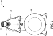
- FIG. 1 illustrates a fluid pump assembly 100.
- the fluid pump assembly 100 may serve to convey a fluid, in particular water, from a source or from a storage vessel into a water line network, which may be provided, for example, for supplying a building and/or a garden.
- the fluid pump assembly 100 may be made from plastic, cast iron, stainless steel, cast steel, bronze, composite materials, carbon structural steel, alloy steel, or any other suitable material commonly known and utilized in the related art to provide strength and rigidity to the fluid pump assembly 100 against external or internal pressure or forces, such as, but not limited to, difference in working fluid pressure in different sections of the fluid pump assembly 100.
- the fluid pump assembly 100 includes a fluid pump housing 110.
- the fluid pump housing 110 includes a drive motor 112 and a fluid pump 115 coupled to the drive motor 112.
- the drive motor 112 includes a motor shaft 111 which is mounted with ball bearings 113 and on each of which a fan wheel 114 and a fluid pump impeller 116 are mounted at the ends.
- the fluid pump impeller 116 has an essentially disk-shaped outer contour and is provided with guide vanes, which are provided for a radially outwardly directed delivery of the fluid during a rotational movement of the fluid pump impeller 116.
- the fluid pump impeller 116 is disposed in a fluid pump chamber 122 defined within the fluid pump housing 110.
- the fluid pump assembly 100 further includes a suction side inlet channel 117 and a pressure side outlet channel 118.
- the suction side inlet channel 117 allows for the introduction or inlet of the fluid to the fluid pump assembly 100 whereas the pressure side outlet channel 118 allows for the delivery or outlet of the pressurized fluid from the fluid pump assembly 100 for various domestic and industrial applications.
- the suction side inlet channel 117 is disposed in an end region of the fluid pump housing 110 facing away from the drive motor 112.
- the suction side inlet channel 117 is fluidly connected to the fluid pump housing 110 via a vertical channel 119.
- the vertical channel 119 provides passage to the fluid entering the fluid pump assembly 100 towards the fluid pump chamber 122 via an opening 132.
- the opening 132 is marginally above the bottom surface of the vertical channel 119 parallel to a central longitudinal axis X-X' (as shown in FIG. 3 ) of the vertical channel 119.
- the vertical channel 119 is equipped with a filter assembly 120.
- the filter assembly 120 is arranged downstream of the suction side inlet channel 117.
- the filter assembly 120 includes a filter network which is supported by a supporting structure.
- the filter assembly 120 may prevent damage to the fluid pump 115 by particles such as sand grains contained in the fluid.
- the filter assembly 120 may be made from plastic or any other suitable light-weight material known in the related art.
- the filter assembly 120 may be removably arranged in the vertical channel 119 of the fluid pump housing 110 from top of the vertical channel 119 such that the top of the vertical channel 119 is covered by a cap 121 after the insertion of the filter assembly 120 in the vertical channel 119 of the fluid pump housing 110.
- the cap 121 prevents the entry of the foreign elements (present in the surroundings of the fluid pump assembly 100) in the vertical channel 119 and hence the filter assembly 120 to allow efficient working of the filter assembly 120.
- the cap 121 may be threadedly engaged with the vertical channel 119 and may be removed when the filter assembly 120 is to be removed from the fluid pump housing 110 for maintenance or cleaning purposes.
- a valve assembly 123 is arranged downstream of the filter assembly 120 for selectively allowing flow of fluid from the suction side inlet channel 117 towards the pressure side outlet channel 118 disposed in the fluid pump chamber 122.
- valve assembly 123 may be fixedly coupled to the vertical channel 119 by any means known in the related art.
- the valve assembly 123 may be advantageously coupled with the vertical channel 119 such that the valve assembly 123 may be able to absorb forces due to the differential pressure in the fluid pump assembly 100.
- the differential may be due to the pressure difference between suction side and pressure side of the fluid pump assembly 100.
- the valve assembly 123 is removably disposed in the vertical channel 119 of the fluid pump housing 110 and is spatially arranged downstream of the filter assembly 120.
- the valve assembly 123 is operatively coupled with the filter assembly 120 such that the valve assembly 123 and the filter assembly 120 may together be removed or withdrawn from the vertical channel 119 of the fluid pump housing 110 for maintenance or cleaning purposes which is advantageous over the prior art where the valve assembly 120 is not coupled to the filter assembly.
- the valve assembly 123 and the filter assembly 120 may be fixedly coupled to one another.
- the valve assembly 123 and the filter assembly 120 may be removably coupled to one another.
- the valve assembly 123 may be removably coupled to the filter assembly 120 for easy maintenance and thorough cleaning of individual assemblies.
- the coupling between the valve assembly 123 and the filter assembly 120 may be achieved by any suitable means known in the related art such as, but not limited to, use of adhesives, snap fitting among others.
- the center of the valve assembly 123 may be along the central longitudinal axis X-X'. In some embodiments, the center of the valve assembly 123 may be slightly offset from the central longitudinal axis X-X'. However, in actual implementation of the present disclosure, the valve assembly 123 may have any orientation with respect to the central longitudinal axis X-X' or the filter assembly 120 or the vertical channel 119 as per the feasibility of the operation of the fluid pump assembly 100 and without limiting the scope of the present disclosure in any manner.
- the valve assembly 123 of the present disclosure corresponds to the assembly of a non-return valve.
- the non-return valve may be employed for blocking fluid pressure which may be applied by the fluid pump 115.
- the non-return valve prevents the fluid pressure built up by the fluid pump 115 from dropping due to the outflow of fluid into the suction side inlet channel 117.
- the valve assembly 123 includes a valve housing 124.
- the valve housing 124 includes a valve seat 125 for operatively supporting a valve body 126.
- the valve body 126 includes an O-ring 134 around its outer periphery to prevent potential leakages.
- any other sealing element 134 is within the scope of the present disclosure.
- a valve stem 127 is operatively coupled to the valve body 126.
- a spring 128 is disposed around the valve stem 127.
- the spring 128 is one or more of a compression spring and a disc spring. The spring 128 may be chosen based on application requirement, space constraint in the fluid pump assembly 100, among other factors. Further, the disc spring may allow for compact design of the fluid pump assembly 100.
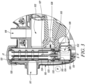
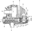
- the spring 128 allows the valve body 126 to move between a first position "P 1 " (as shown in FIGS. 2 and 3 ) and a second position "P2" (as shown in FIGS. 4 and 5 ).
- the valve assembly 123 disallows the flow of fluid from the suction side inlet channel 117 towards the pressure side outlet channel 118 in the first position "P 1 " of the valve body 126.
- the valve assembly 123 disallows the flow of fluid from the suction side inlet channel 117 towards the fluid pump chamber 122 in the first position "P 1 " of the valve body 126.
- the valve assembly 123 allows the flow of fluid from the suction side inlet channel 117 towards the pressure side outlet channel 118 in the second position "P 2 " of the valve body 126.
- the valve assembly 123 allows the flow of fluid from the suction side inlet channel 117 towards the fluid pump chamber 122 in the second position "P 2 " of the valve body 126.
- the valve body 126 in the second position "P 2 " of the valve body 126 is positioned such that the flow of fluid is upstream of the valve body 126 or at least partly upstream of the valve body 126.
- the valve body 126 in the second position "P 2 " of the valve body 126 is positioned such that the valve body 126 is at least partly below the opening 132.
- the second position "P 2 " of the valve body 126 is advantageously defined such as to avoid or prevent obstruction of the fluid flowing from the suction side inlet channel 117 towards the pressure side outlet channel 119 of the fluid pump assembly 100.
- the free flow of the fluid without obstruction of fluid flow due to the valve body 126 minimizes the pressure losses in the fluid pump assembly 100 and improves the working efficiency of the fluid pump assembly 100.
- the fluid pump assembly includes a pressurized container 129.
- the fluid pump housing 110 is fluidly coupled to the pressurized container 129 via a flow channel 130.
- the pressurized container 129 may supplement the fluid pump and may also allow the fluid pump 115 to operate intermittently.
- the fluid pump 115 may be operated intermittently because a continuously operating fluid pump 115 may have a shorter operational lifetime.
- the pressurized container 129 may establish a wired or wireless communication with the drive motor 112 and the fluid pump 115.
- the pressurized container 129 may be essentially designed as a cylindrical pressurized container 129 with a circular opening on the end face, through which a membrane made of elastic material may be introduced into a volume section surrounded by the pressurized container 129.
- the fluid pump assembly 100 includes a pressure relief housing 131 disposed downstream of the filter assembly 120 and the valve assembly 123 is operatively coupled with the pressure relief housing 131.
- the pressure relief housing 131 is arranged downstream of both the filter assembly 120 and the valve assembly 123.
- the pressure relief housing 131 may be made from same or different material to the valve housing 124 as per the application requirement among other factors.
- valve assembly 123 is threadedly coupled to the pressure relief housing 131. In some embodiments, the valve assembly 123 is coupled to the pressure relief housing 131 via a bayonet coupling. The valve assembly 123 may be removably or fixedly coupled to the pressure relief housing 131 as per the application requirements without limiting the scope of the present disclosure. Further, a plurality of sealing elements 133 such as, but not limited to, O-rings 133 may be frictionally engaged between the pressure relief housing 131 and the side walls of the vertical channel 119.
- the pressure relief housing 131 includes the plurality of sealing elements 133 around the outer periphery of the pressure relief housing 131 to prevent the flow of fluid around the outer periphery of the pressure relief housing 131 such as to allow optimum pressure relief for the valve assembly 123. Further, the filter assembly 120, the valve assembly 123 and the pressure relief housing 131 may together be taken out of the fluid pump housing 110 for maintenance or cleaning purposes in the embodiments where the filter assembly 120 is operatively coupled with the valve assembly 123.
- the pressure relief housing 131 includes an opening that aligns with the opening 132 to allow fluid flow from the suction side inlet channel 117 towards the pressure side outlet channel 118.
- the bottom surface of the pressure relief housing 131 and the bottom surface of the vertical channel 119 have a clearance "D" between them as shown in FIGS. 2 , 3 , 4 and 5 .
- the clearance "D” is advantageously provided such as to combat or counteract against the effect of forces generated by the pressure difference in suction side and pressure side of the fluid pump assembly 100 on the valve body 126 or the valve assembly 123 during backflow of the fluid in the fluid pump assembly 100.
- the clearance "D” allows the fluid to apply a downward force on the bottom of the pressure relief housing 131 during backflow of the fluid in the fluid pump assembly 100.
- the downward force on the bottom of the pressure relief housing 131 results in reduction in net force on the valve body 126 or the valve assembly 123 and hence the filter assembly 120 coupled to the valve assembly 123.
- This pressure relief housing 131 and the clearance "D" between the pressure relief housing 131 and the bottom surface of the vertical channel 119 provides advantage over the prior art where there is no provision for counterforce in an opposite direction to reduce the force acting on the valve body 126 or the valve assembly 123 that may damage or deform the filter assembly 120 and/or the valve assembly 123.
- the clearance “D” may be 3 mm. In some embodiments, the clearance “D” may be between 3 mm - 6 mm. However, in actual implementation of the present disclosure, the clearance “D” may depend on various operational and structural factors of the fluid pump assembly 100. Further, the spatial region representing the clearance “D” is well protected from inflow of the backflow fluid. The protection of clearance "D" from backflow fluid for proper functioning of the pressure relief housing 131 is achieved by virtue of the plurality of sealing elements 133 around the periphery of the pressure relief housing 131.
- the present disclosure provides the fluid pump assembly 100 which is advantageously designed in a manner such as to combat or counteract against the effect of forces generated by the pressure difference in suction side and pressure side of the fluid pump assembly 100 on the filter assembly 120 and the valve assembly 123 and prevent damage or deformation of the filter assembly 120 and the valve assembly 123.
- the improved design of the fluid pump assembly 100 provides the pressure relief at the valve assembly 123 and further improves the working life of the fluid pump assembly 100.
- the improved fluid pump assembly 100 allows for the filter assembly 120 with a light design thereby reducing the overall weight of the fluid pump assembly 100.
- the coupling between the filter assembly 120 and the valve assembly 123 allows for easy, fast, and user-friendly removal of the filter assembly 120 and the valve assembly 123 for maintenance or cleaning purposes.
Landscapes
- Engineering & Computer Science (AREA)
- Mechanical Engineering (AREA)
- General Engineering & Computer Science (AREA)
- Details Of Reciprocating Pumps (AREA)
Abstract
Description
- The present disclosure relates to a fluid pump assembly. More specifically, the present disclosure relates to an improved design of the fluid pump assembly that may improve life of the fluid pump assembly and allow its efficient working.
- A fluid pump assembly may serve to convey a fluid, in particular drinking water or service water, from a source or from a storage vessel into a water line network, which may be provided, for example, for supplying a building and/or a garden. The fluid pump assembly may include a fluid pump housing which may further house a drive motor, which may be designed as a mains-operated electric motor, and a fluid pump coupled thereto. The fluid pump may typically be designed as a single-stage or multi-stage self-priming centrifugal pump and may comprise a fluid pump impeller which may be accommodated in the fluid pump housing and may be driven by the drive motor. The fluid pump housing may further include a suction-side inlet channel and a pressure-side outlet channel, which may permit an inflow of fluid to the fluid pump impeller and an outflow of the fluid pressurized by the fluid pump impeller, for example, into the water line network.
- The fluid pump assembly may further include a pressure vessel coupled to a discharge channel of the fluid pump housing such that the pressure vessel may communicate with the pressurized fluid. The pressure vessel may be provided to avoid a frequently recurring switching on and off of the drive motor due to the occurring pressure loss in the event of possibly existing leakages in the water line network. The pressure vessel, which may be designed as a pressure accumulator, may provide a limited fluid volume which is pressurized by means of the fluid pump and ensures an essentially constant water pressure at least when small amounts of fluid flow into the water line network.
- The fluid pump assembly or the fluid pump housing thereof may further include a non-return valve located between the suction-side inlet channel and the pressure vessel. The non-return valve prevents back flow of the pressurized fluid when the fluid pump is in a non-operational state. The fluid pump assembly may further include a filter assembly upstream of the non-return valve to filter the fluid received from the source by the fluid pump assembly.
- An example of a fluid pump assembly is provided in
European patent 2 211 057 (hereinafter referred to as '057 reference). The '057 reference provides a pump device that includes a drive motor and a fluid pump which is coupled to the drive motor. The pump device further includes a pump housing with at least one suction-side inflow channel and one pressure-side outflow channel and having a pressure container which is coupled to the outflow channel of the fluid pump to communicate with it. At least one non-return valve is arranged near the suction-side inflow channel such that when the fluid pump starts up, the non-return valve opens the inflow duct because of the negative pressure arising in the pump housing and allows fluid to flow in from the source. Further, a filter assembly is disposed upstream of the non-return valve. However, the '057 reference seems short of disclosing the design improvements to combat the effect of forces generated by the pressure difference in suction side and pressure side of the fluid pump assembly on the functional components, such as the filter assembly and the non-return valve or on the structural components such as those binding the functional components with the fluid pump assembly and further prevent damage or deformation of the functional or structural components of the fluid pump assembly. - Thus, there is a need of an improved fluid pump assembly which has an improved design to improve a working efficiency of the fluid pump assembly and further improve life-span of the components of the fluid pump assembly.
- In view of the above, it is an objective of the present invention to solve or at least reduce the drawbacks discussed above. The objective is at least partially achieved by a fluid pump assembly. The fluid pump assembly includes a fluid pump housing. The fluid pump housing includes a drive motor and a fluid pump coupled to the drive motor. The fluid pump assembly further includes a suction side inlet channel and a pressure side outlet channel. A filter assembly is arranged downstream of the suction side inlet channel. A valve assembly is arranged downstream of the filter assembly for selectively allowing flow of fluid from the suction side inlet channel towards the pressure side outlet channel. The valve assembly includes a valve housing. The valve housing includes a valve seat for operatively supporting a valve body. A valve stem is operatively coupled to the valve body. Further, a spring is disposed around the valve stem to allow the valve body to move between a first position and a second position. The valve assembly disallows the flow of fluid from the suction side inlet channel towards the pressure side outlet channel in the first position of the valve body. The valve assembly allows the flow of fluid from the suction side inlet channel towards the pressure side outlet channel in the second position of the valve body. The fluid pump assembly is characterized in that the fluid pump assembly further comprises a pressure relief housing disposed downstream of the valve assembly. The valve assembly is operatively coupled with the pressure relief housing. Hereby the pressure relief housing is formed on the pressure side of the fluid pump assembly such that the forces introduced on it combat or counteract against the effect of forces on the valve body or the valve assembly generated by the pressure difference in suction side and pressure side of the fluid pump assembly.
- Thus, the present disclosure provides the fluid pump assembly which is advantageously designed in a manner such as to combat or counteract against the effect of forces generated by the pressure difference in suction side and pressure side of the fluid pump assembly on the valve assembly and prevent damage or deformation of the valve assembly. As there are less pressure forces acting on the valve assembly there is also less force onto the connection of the valve assembly with any part of the fluid pump assembly, so that they can be designed less force prove and/or bulky. In the same way the valve assembly does transfer much less pressure than usually (without pressure relief housing) towards any components connected to it (for example a filter arrangement) so that they can be designed less force prove and/or bulky. Thus the improved design of the fluid pump assembly provides the pressure relief at the valve assembly and further improves the working life of the fluid pump assembly.
- According to an embodiment of the present disclosure a clearance "D" is formed by a sealed space between the pressure relief housing and a vertical channel of the fluid pump assembly, preferably its bottom surface, introducing a force combating or counteracting the force on the valve body or the valve assembly. Advantageously the pressure within this clearance "D" is significantly lower than the pressure within the pressure side within the fluid pump assembly, preferably the pressure is the same or even less than the pressure on the suction side.
- According to an embodiment of the present disclosure, the valve assembly is operatively coupled with the filter assembly. The coupling between the filter assembly and the valve assembly allows for easy, fast, and user-friendly removal of the filter assembly and the valve assembly for maintenance or cleaning purposes.
- According to an embodiment of the present disclosure, the valve assembly is threadedly coupled to the pressure relief housing. In some embodiments, the valve assembly is coupled to the pressure relief housing via a bayonet coupling. The valve assembly may be removably or fixedly coupled to the pressure relief housing as per the application requirements without limiting the scope of the present disclosure.
- According to an embodiment of the present disclosure, the valve assembly is removably coupled to the filter assembly. The valve assembly may be removably coupled to the filter assembly for easy maintenance and thorough cleaning of individual assemblies.
- According to an embodiment of the present disclosure, the fluid pump housing is fluidly coupled to a pressurized container. The pressurized container may supplement the fluid pump and may also allow the fluid pump to operate intermittently. The fluid pump may be operated intermittently because a continuously operating fluid pump may have a shorter operational lifetime.
- According to an embodiment of the present disclosure, the spring is one or more of a compression spring and a disc spring. The spring may be chosen based on application requirement. Further, the disc spring may allow for compact design of the fluid pump assembly.
- According to an embodiment of the present disclosure, the valve assembly corresponds to the assembly of a non-return valve. The non-return valve may be employed for blocking fluid pressure which may be applied by the fluid pump. The non-return valve prevents the fluid pressure built up by the fluid pump from dropping due to the outflow of fluid into the suction side inlet channel.
- According to an embodiment of the present disclosure, the valve body in the second position of the valve body is positioned such that the flow of fluid is upstream of the valve body. The second position of the valve body is advantageously defined such as to avoid or prevent obstruction of the fluid flowing from the suction side inlet channel towards the pressure side outlet channel of the fluid pump assembly. The free flow of the fluid without obstruction of fluid flow due to the valve body minimizes the pressure losses in the fluid pump assembly and improves the working efficiency of the fluid pump assembly.
- According to an embodiment of the present disclosure, the pressure relief housing includes a plurality of sealing elements around the outer periphery of the pressure relief housing. The plurality of sealing elements prevents the flow of fluid around the outer periphery of the pressure relief housing such as to allow optimum pressure relief for the valve assembly.
- Other features and aspects of this invention will be apparent from the following description and the accompanying drawings.
- The invention will be described in more detail with reference to the enclosed drawings, wherein:
-
FIG. 1 shows a front view of a fluid pump assembly, in accordance with an aspect of the present disclosure; -
FIG. 2 shows a side cross-sectional view of a fluid pump assembly with a valve body in first position, in accordance with an aspect of the present disclosure; -
FIG. 3 shows an enlarged view of a portion of the fluid pump assembly ofFIG. 2 , in accordance with an aspect of the present disclosure; -
FIG. 4 shows a side cross-sectional view of a fluid pump assembly with a valve body in second position, in accordance with an aspect of the present disclosure; and -
FIG. 5 shows an enlarged view of a portion of the fluid pump assembly ofFIG. 4 , in accordance with an aspect of the present disclosure. - The present invention will be described more fully hereinafter with reference to the accompanying drawings, in which example embodiments of the invention incorporating one or more aspects of the present invention are shown. This invention may, however, be embodied in many different forms and should not be construed as limited to the embodiments set forth herein; rather, these embodiments are provided so that this disclosure will be thorough and complete, and will fully convey the scope of the invention to those skilled in the art. For example, one or more aspects of the present invention may be utilized in other embodiments and even other types of structures and/or methods. In the drawings, like numbers refer to like elements.
- Certain terminology is used herein for convenience only and is not to be taken as a limitation on the invention. For example, "upper", "lower", "front", "rear", "side", "longitudinal", "lateral", "transverse", "upwards", "downwards", "forward", "backward", "sideward", "left," "right," "horizontal," "vertical," "upward", "inner", "outer", "inward", "outward", "top", "bottom", "higher", "above", "below", "central", "middle", "intermediate", "between", "end", "adjacent", "proximate", "near", "distal", "remote", "radial", "circumferential", or the like, merely describe the configuration shown in the Figures. Indeed, the components may be oriented in any direction and the terminology, therefore, should be understood as encompassing such variations unless specified otherwise.
-
FIG. 1 illustrates afluid pump assembly 100. Thefluid pump assembly 100 may serve to convey a fluid, in particular water, from a source or from a storage vessel into a water line network, which may be provided, for example, for supplying a building and/or a garden. Thefluid pump assembly 100 may be made from plastic, cast iron, stainless steel, cast steel, bronze, composite materials, carbon structural steel, alloy steel, or any other suitable material commonly known and utilized in the related art to provide strength and rigidity to thefluid pump assembly 100 against external or internal pressure or forces, such as, but not limited to, difference in working fluid pressure in different sections of thefluid pump assembly 100. - The
fluid pump assembly 100, as shown inFIGS. 1 and2 , includes afluid pump housing 110. Thefluid pump housing 110 includes adrive motor 112 and afluid pump 115 coupled to thedrive motor 112. Thedrive motor 112 includes amotor shaft 111 which is mounted withball bearings 113 and on each of which afan wheel 114 and afluid pump impeller 116 are mounted at the ends. Thefluid pump impeller 116 has an essentially disk-shaped outer contour and is provided with guide vanes, which are provided for a radially outwardly directed delivery of the fluid during a rotational movement of thefluid pump impeller 116. Thefluid pump impeller 116 is disposed in afluid pump chamber 122 defined within thefluid pump housing 110. - The
fluid pump assembly 100 further includes a suctionside inlet channel 117 and a pressureside outlet channel 118. The suctionside inlet channel 117 allows for the introduction or inlet of the fluid to thefluid pump assembly 100 whereas the pressureside outlet channel 118 allows for the delivery or outlet of the pressurized fluid from thefluid pump assembly 100 for various domestic and industrial applications. - The suction
side inlet channel 117 is disposed in an end region of thefluid pump housing 110 facing away from thedrive motor 112. The suctionside inlet channel 117 is fluidly connected to thefluid pump housing 110 via avertical channel 119. Thevertical channel 119 provides passage to the fluid entering thefluid pump assembly 100 towards thefluid pump chamber 122 via anopening 132. Theopening 132 is marginally above the bottom surface of thevertical channel 119 parallel to a central longitudinal axis X-X' (as shown inFIG. 3 ) of thevertical channel 119. Further, thevertical channel 119 is equipped with afilter assembly 120. Thefilter assembly 120 is arranged downstream of the suctionside inlet channel 117. Thefilter assembly 120 includes a filter network which is supported by a supporting structure. Thefilter assembly 120 may prevent damage to thefluid pump 115 by particles such as sand grains contained in the fluid. Thefilter assembly 120 may be made from plastic or any other suitable light-weight material known in the related art. - The
filter assembly 120 may be removably arranged in thevertical channel 119 of thefluid pump housing 110 from top of thevertical channel 119 such that the top of thevertical channel 119 is covered by acap 121 after the insertion of thefilter assembly 120 in thevertical channel 119 of thefluid pump housing 110. Thecap 121 prevents the entry of the foreign elements (present in the surroundings of the fluid pump assembly 100) in thevertical channel 119 and hence thefilter assembly 120 to allow efficient working of thefilter assembly 120. In some embodiments, thecap 121 may be threadedly engaged with thevertical channel 119 and may be removed when thefilter assembly 120 is to be removed from thefluid pump housing 110 for maintenance or cleaning purposes. - Further, as shown in
FIGS. 2 and3 , avalve assembly 123 is arranged downstream of thefilter assembly 120 for selectively allowing flow of fluid from the suctionside inlet channel 117 towards the pressureside outlet channel 118 disposed in thefluid pump chamber 122. - In some embodiments, the
valve assembly 123 may be fixedly coupled to thevertical channel 119 by any means known in the related art. Thevalve assembly 123 may be advantageously coupled with thevertical channel 119 such that thevalve assembly 123 may be able to absorb forces due to the differential pressure in thefluid pump assembly 100. The differential may be due to the pressure difference between suction side and pressure side of thefluid pump assembly 100. - In some embodiments, the
valve assembly 123 is removably disposed in thevertical channel 119 of thefluid pump housing 110 and is spatially arranged downstream of the filter assembly 120.Thevalve assembly 123 is operatively coupled with thefilter assembly 120 such that thevalve assembly 123 and thefilter assembly 120 may together be removed or withdrawn from thevertical channel 119 of thefluid pump housing 110 for maintenance or cleaning purposes which is advantageous over the prior art where thevalve assembly 120 is not coupled to the filter assembly. In some embodiments, thevalve assembly 123 and thefilter assembly 120 may be fixedly coupled to one another. In some embodiments, thevalve assembly 123 and thefilter assembly 120 may be removably coupled to one another. Thevalve assembly 123 may be removably coupled to thefilter assembly 120 for easy maintenance and thorough cleaning of individual assemblies. The coupling between thevalve assembly 123 and thefilter assembly 120, whether permanent or removable, may be achieved by any suitable means known in the related art such as, but not limited to, use of adhesives, snap fitting among others. - In some embodiments, the center of the
valve assembly 123 may be along the central longitudinal axis X-X'. In some embodiments, the center of thevalve assembly 123 may be slightly offset from the central longitudinal axis X-X'. However, in actual implementation of the present disclosure, thevalve assembly 123 may have any orientation with respect to the central longitudinal axis X-X' or thefilter assembly 120 or thevertical channel 119 as per the feasibility of the operation of thefluid pump assembly 100 and without limiting the scope of the present disclosure in any manner. - The
valve assembly 123 of the present disclosure corresponds to the assembly of a non-return valve. The non-return valve may be employed for blocking fluid pressure which may be applied by thefluid pump 115. The non-return valve prevents the fluid pressure built up by thefluid pump 115 from dropping due to the outflow of fluid into the suctionside inlet channel 117. - The
valve assembly 123 includes avalve housing 124. Thevalve housing 124 includes avalve seat 125 for operatively supporting avalve body 126. Thevalve body 126 includes an O-ring 134 around its outer periphery to prevent potential leakages. However, any other sealingelement 134 is within the scope of the present disclosure. Avalve stem 127 is operatively coupled to thevalve body 126. Further, aspring 128 is disposed around thevalve stem 127. Thespring 128 is one or more of a compression spring and a disc spring. Thespring 128 may be chosen based on application requirement, space constraint in thefluid pump assembly 100, among other factors. Further, the disc spring may allow for compact design of thefluid pump assembly 100. - The
spring 128 allows thevalve body 126 to move between a first position "P1" (as shown inFIGS. 2 and3 ) and a second position "P2" (as shown inFIGS. 4 and5 ). Thevalve assembly 123 disallows the flow of fluid from the suctionside inlet channel 117 towards the pressureside outlet channel 118 in the first position "P1" of thevalve body 126. Thevalve assembly 123 disallows the flow of fluid from the suctionside inlet channel 117 towards thefluid pump chamber 122 in the first position "P1" of thevalve body 126. Further, thevalve assembly 123 allows the flow of fluid from the suctionside inlet channel 117 towards the pressureside outlet channel 118 in the second position "P2" of thevalve body 126. Thevalve assembly 123 allows the flow of fluid from the suctionside inlet channel 117 towards thefluid pump chamber 122 in the second position "P2" of thevalve body 126. - In a preferred embodiment of the present disclosure, the
valve body 126 in the second position "P2" of thevalve body 126 is positioned such that the flow of fluid is upstream of thevalve body 126 or at least partly upstream of thevalve body 126. Thevalve body 126 in the second position "P2" of thevalve body 126 is positioned such that thevalve body 126 is at least partly below theopening 132. The second position "P2" of thevalve body 126 is advantageously defined such as to avoid or prevent obstruction of the fluid flowing from the suctionside inlet channel 117 towards the pressureside outlet channel 119 of thefluid pump assembly 100. The free flow of the fluid without obstruction of fluid flow due to thevalve body 126 minimizes the pressure losses in thefluid pump assembly 100 and improves the working efficiency of thefluid pump assembly 100. - Further, as shown in
FIGS. 1 ,2 and4 , the fluid pump assembly includes apressurized container 129. Thefluid pump housing 110 is fluidly coupled to thepressurized container 129 via aflow channel 130. Thepressurized container 129 may supplement the fluid pump and may also allow thefluid pump 115 to operate intermittently. Thefluid pump 115 may be operated intermittently because a continuously operatingfluid pump 115 may have a shorter operational lifetime. Thepressurized container 129 may establish a wired or wireless communication with thedrive motor 112 and thefluid pump 115. Further, thepressurized container 129 may be essentially designed as a cylindricalpressurized container 129 with a circular opening on the end face, through which a membrane made of elastic material may be introduced into a volume section surrounded by thepressurized container 129. - Further, in the preferred embodiment of the present disclosure, as shown clearly in an enlarged view in
FIGS. 3 and5 , thefluid pump assembly 100 includes apressure relief housing 131 disposed downstream of thefilter assembly 120 and thevalve assembly 123 is operatively coupled with thepressure relief housing 131. Thepressure relief housing 131 is arranged downstream of both thefilter assembly 120 and thevalve assembly 123. Thepressure relief housing 131 may be made from same or different material to thevalve housing 124 as per the application requirement among other factors. - In some embodiments, the
valve assembly 123 is threadedly coupled to thepressure relief housing 131. In some embodiments, thevalve assembly 123 is coupled to thepressure relief housing 131 via a bayonet coupling. Thevalve assembly 123 may be removably or fixedly coupled to thepressure relief housing 131 as per the application requirements without limiting the scope of the present disclosure. Further, a plurality of sealingelements 133 such as, but not limited to, O-rings 133 may be frictionally engaged between thepressure relief housing 131 and the side walls of thevertical channel 119. Thepressure relief housing 131 includes the plurality of sealingelements 133 around the outer periphery of thepressure relief housing 131 to prevent the flow of fluid around the outer periphery of thepressure relief housing 131 such as to allow optimum pressure relief for thevalve assembly 123. Further, thefilter assembly 120, thevalve assembly 123 and thepressure relief housing 131 may together be taken out of thefluid pump housing 110 for maintenance or cleaning purposes in the embodiments where thefilter assembly 120 is operatively coupled with thevalve assembly 123. - The
pressure relief housing 131 includes an opening that aligns with theopening 132 to allow fluid flow from the suctionside inlet channel 117 towards the pressureside outlet channel 118. The bottom surface of thepressure relief housing 131 and the bottom surface of thevertical channel 119 have a clearance "D" between them as shown inFIGS. 2 ,3 ,4 and5 . - The clearance "D" is advantageously provided such as to combat or counteract against the effect of forces generated by the pressure difference in suction side and pressure side of the
fluid pump assembly 100 on thevalve body 126 or thevalve assembly 123 during backflow of the fluid in thefluid pump assembly 100. The clearance "D" allows the fluid to apply a downward force on the bottom of thepressure relief housing 131 during backflow of the fluid in thefluid pump assembly 100. The downward force on the bottom of thepressure relief housing 131 results in reduction in net force on thevalve body 126 or thevalve assembly 123 and hence thefilter assembly 120 coupled to thevalve assembly 123. Thispressure relief housing 131 and the clearance "D" between thepressure relief housing 131 and the bottom surface of thevertical channel 119 provides advantage over the prior art where there is no provision for counterforce in an opposite direction to reduce the force acting on thevalve body 126 or thevalve assembly 123 that may damage or deform thefilter assembly 120 and/or thevalve assembly 123. - In some embodiments, the clearance "D" may be 3 mm. In some embodiments, the clearance "D" may be between 3 mm - 6 mm. However, in actual implementation of the present disclosure, the clearance "D" may depend on various operational and structural factors of the
fluid pump assembly 100. Further, the spatial region representing the clearance "D" is well protected from inflow of the backflow fluid. The protection of clearance "D" from backflow fluid for proper functioning of thepressure relief housing 131 is achieved by virtue of the plurality of sealingelements 133 around the periphery of thepressure relief housing 131. - Thus, the present disclosure provides the
fluid pump assembly 100 which is advantageously designed in a manner such as to combat or counteract against the effect of forces generated by the pressure difference in suction side and pressure side of thefluid pump assembly 100 on thefilter assembly 120 and thevalve assembly 123 and prevent damage or deformation of thefilter assembly 120 and thevalve assembly 123. The improved design of thefluid pump assembly 100 provides the pressure relief at thevalve assembly 123 and further improves the working life of thefluid pump assembly 100. The improvedfluid pump assembly 100 allows for thefilter assembly 120 with a light design thereby reducing the overall weight of thefluid pump assembly 100. Further, the coupling between thefilter assembly 120 and thevalve assembly 123 allows for easy, fast, and user-friendly removal of thefilter assembly 120 and thevalve assembly 123 for maintenance or cleaning purposes. - In the drawings and specification, there have been disclosed preferred embodiments and examples of the invention and, although specific terms are employed, they are used in a generic and descriptive sense only and not for the purpose of limitation of the scope of the invention being set forth in the following claims.
-
- 100
- Fluid Pump Assembly
- 110
- Fluid Pump Housing
- 111
- Motor Shaft
- 112
- Drive Motor
- 113
- Ball Bearings
- 114
- Fan Wheel
- 115
- Fluid Pump
- 116
- Fluid Pump Impeller
- 117
- Suction Side Inlet Channel
- 118
- Pressure Side Outlet Channel
- 119
- Vertical Channel
- 120
- Filter Assembly
- 121
- Cap
- 122
- Fluid Pump Chamber
- 123
- Valve Assembly
- 124
- Valve Housing
- 125
- Valve Seat
- 126
- Valve Body
- 127
- Valve Stem
- 128
- Spring
- 129
- Pressurized Container
- 130
- Flow Channel
- 131
- Pressure Relief Housing
- 132
- Opening
- 133
- O-rings, Sealing Elements
- 134
- O-rings, Sealing Elements
- P1
- First Position
- P2
- Second Position
- X-X'
- Central Longitudinal Axis
- D
- Clearance
Claims (11)
- A fluid pump assembly (100) comprising:
a fluid pump housing (110), wherein the fluid pump housing (110) comprising:a drive motor (112);a fluid pump (115) coupled to the drive motor (112);a suction side inlet channel (117) and a pressure side outlet channel (118);a filter assembly (120) arranged downstream of the suction side inlet channel (117);a valve assembly (123) arranged downstream of the filter assembly (120) for selectively allowing flow of fluid from the suction side inlet channel (117) towards the pressure side outlet channel (118),wherein the valve assembly (123) comprises:a valve housing (124), wherein the valve housing (124) includes a valve seat (125) for operatively supporting a valve body (126);a valve stem (127) operatively coupled with the valve body (126); anda spring (128) disposed around the valve stem (127) to allow the valve body (126) to move between a first position (P1)and a second position (P2) such that the valve assembly (123) disallows the flow of fluid from the suction side inlet channel (117) towards the pressure side outlet channel (118) in the first position (P1) of the valve body (126) and the valve assembly (123) allows the flow of fluid from the suction side inlet channel (117) towards the pressure side outlet channel (118) in the second position (P2) of the valve body (126);characterized in that:the fluid pump assembly (100) further comprises a pressure relief housing (131) disposed downstream of and operatively coupled to the valve assembly (123),wherein the pressure relief housing is formed on the pressure side of the fluid pump assembly (100) such that the forces introduced on it combat or counteract against the effect of forces on the valve body (126) or the valve assembly (123) generated by the pressure difference in suction side and pressure side of the fluid pump assembly (100). - The fluid pump assembly (100) of claim 1, wherein a clearance "D" is formed by a sealed space between the pressure relief housing (131) and a vertical channel (119) of the fluid pump assembly (100), preferably its bottom surface, introducing a force combating or counteracting the force on the valve body (126) or the valve assembly (123).
- The fluid pump assembly (100) of any one of , wherein the valve assembly (123) is operatively coupled with the filter assembly (120).
- The fluid pump assembly (100) of any one of the preceding claims, wherein the valve assembly (123) is threadedly coupled to the pressure relief housing (131).
- The fluid pump assembly (100) of any one of the preceding claims, wherein the valve assembly (123) is coupled to the pressure relief housing (131) via a bayonet coupling.
- The fluid pump assembly (100) of any one of the preceding claims, wherein the valve assembly (123) is removably coupled to the filter assembly (120).
- The fluid pump assembly (100) of any one of the preceding claims, wherein the fluid pump housing (110) is fluidly coupled to a pressurized container (129).
- The fluid pump assembly (100) of any one of the preceding claims, wherein the spring (128) is one or more of a compression spring and a disc spring.
- The fluid pump assembly (100) of any one of the preceding claims, wherein the valve assembly (123) corresponds to the assembly of a non-return valve.
- The fluid pump assembly (100) of any one of the preceding claims, wherein the valve body (126) in the second position (P2) of the valve body (126) is positioned such that the flow of fluid is upstream of the valve body (126).
- The fluid pump assembly (100) of any one of the preceding claims, wherein the pressure relief housing (131) includes a plurality of sealing elements (133) around the outer periphery of the pressure relief housing (131).
Priority Applications (3)
| Application Number | Priority Date | Filing Date | Title |
|---|---|---|---|
| EP22175169.6A EP4283128A1 (en) | 2022-05-24 | 2022-05-24 | Fluid pump assembly |
| CN202211734037.8A CN117108514A (en) | 2022-05-24 | 2022-12-30 | Fluid pump assembly |
| CN202223603404.9U CN220015508U (en) | 2022-05-24 | 2022-12-30 | Fluid pump assembly |
Applications Claiming Priority (1)
| Application Number | Priority Date | Filing Date | Title |
|---|---|---|---|
| EP22175169.6A EP4283128A1 (en) | 2022-05-24 | 2022-05-24 | Fluid pump assembly |
Publications (1)
| Publication Number | Publication Date |
|---|---|
| EP4283128A1 true EP4283128A1 (en) | 2023-11-29 |
Family
ID=81850095
Family Applications (1)
| Application Number | Title | Priority Date | Filing Date |
|---|---|---|---|
| EP22175169.6A Pending EP4283128A1 (en) | 2022-05-24 | 2022-05-24 | Fluid pump assembly |
Country Status (2)
| Country | Link |
|---|---|
| EP (1) | EP4283128A1 (en) |
| CN (2) | CN117108514A (en) |
Citations (4)
| Publication number | Priority date | Publication date | Assignee | Title |
|---|---|---|---|---|
| DE4304149C1 (en) * | 1993-02-12 | 1994-09-08 | Grundfos As | Self-priming motor pump unit |
| DE19923351A1 (en) * | 1998-10-07 | 2000-04-13 | Gardena Kress & Kastner Gmbh | Liquid pump arrangement, in particular for use in the home and / or garden |
| EP2211057A1 (en) | 2005-07-26 | 2010-07-28 | GARDENA Manufacturing GmbH | Pump device |
| EP3225851A1 (en) * | 2016-04-01 | 2017-10-04 | Oase GmbH | Water pump with check valve |
-
2022
- 2022-05-24 EP EP22175169.6A patent/EP4283128A1/en active Pending
- 2022-12-30 CN CN202211734037.8A patent/CN117108514A/en active Pending
- 2022-12-30 CN CN202223603404.9U patent/CN220015508U/en active Active
Patent Citations (4)
| Publication number | Priority date | Publication date | Assignee | Title |
|---|---|---|---|---|
| DE4304149C1 (en) * | 1993-02-12 | 1994-09-08 | Grundfos As | Self-priming motor pump unit |
| DE19923351A1 (en) * | 1998-10-07 | 2000-04-13 | Gardena Kress & Kastner Gmbh | Liquid pump arrangement, in particular for use in the home and / or garden |
| EP2211057A1 (en) | 2005-07-26 | 2010-07-28 | GARDENA Manufacturing GmbH | Pump device |
| EP3225851A1 (en) * | 2016-04-01 | 2017-10-04 | Oase GmbH | Water pump with check valve |
Also Published As
| Publication number | Publication date |
|---|---|
| CN117108514A (en) | 2023-11-24 |
| CN220015508U (en) | 2023-11-14 |
Similar Documents
| Publication | Publication Date | Title |
|---|---|---|
| US5704761A (en) | Full-circumferential flow pump | |
| CN106907348B (en) | Impeller and pump using same | |
| US7946810B2 (en) | Multistage pump assembly | |
| US9239056B2 (en) | Pump impeller and submersible pump having such pump impeller | |
| US8172523B2 (en) | Multistage pump assembly having removable cartridge | |
| CN104350282B (en) | The reciprocal scuttlebutt drive device of integral type | |
| CA2540556A1 (en) | Two-stage sewage grinder pump | |
| CN218407954U (en) | Horizontal centrifugal pump with filtering capability | |
| KR20160060763A (en) | Liquid ring pump with modular construction, an inter-stage bypass and overload protection | |
| KR101735725B1 (en) | Grinder pump | |
| CN114109850A (en) | Self-priming pump with reflux valve | |
| JP2020535346A (en) | Pump with wear ring | |
| EP1571343B1 (en) | Automotive motor-compressor assembly | |
| CN220015508U (en) | Fluid pump assembly | |
| US20120163956A1 (en) | Pressure Compensating Wet Seal Chamber | |
| EP0648934B1 (en) | Full-circumferential flow pump | |
| CN209781221U (en) | Volute type strong self-priming sectional multistage centrifugal pump | |
| JPH03199693A (en) | Circular flow type liquid pump | |
| WO2007070596A3 (en) | Fuel cell compressor system | |
| EP1415094B1 (en) | Pulp pump | |
| CN215521287U (en) | Multi-stage pump with novel structure | |
| RU77652U1 (en) | CENTRIFUGAL MULTI-STAGE ELECTRIC PUMP "VODOMET" | |
| CN117948290B (en) | Axial flow fan | |
| CN222415275U (en) | Stainless steel high suction range deep well pump | |
| CN217794929U (en) | Sewage cutting pump with filtering capability |
Legal Events
| Date | Code | Title | Description |
|---|---|---|---|
| PUAI | Public reference made under article 153(3) epc to a published international application that has entered the european phase |
Free format text: ORIGINAL CODE: 0009012 |
|
| STAA | Information on the status of an ep patent application or granted ep patent |
Free format text: STATUS: THE APPLICATION HAS BEEN PUBLISHED |
|
| AK | Designated contracting states |
Kind code of ref document: A1 Designated state(s): AL AT BE BG CH CY CZ DE DK EE ES FI FR GB GR HR HU IE IS IT LI LT LU LV MC MK MT NL NO PL PT RO RS SE SI SK SM TR |
|
| STAA | Information on the status of an ep patent application or granted ep patent |
Free format text: STATUS: REQUEST FOR EXAMINATION WAS MADE |
|
| 17P | Request for examination filed |
Effective date: 20231214 |
|
| RBV | Designated contracting states (corrected) |
Designated state(s): AL AT BE BG CH CY CZ DE DK EE ES FI FR GB GR HR HU IE IS IT LI LT LU LV MC MK MT NL NO PL PT RO RS SE SI SK SM TR |
|
| STAA | Information on the status of an ep patent application or granted ep patent |
Free format text: STATUS: EXAMINATION IS IN PROGRESS |
|
| 17Q | First examination report despatched |
Effective date: 20250328 |