EP4282765B1 - Hilfstriebwerkssystem eines flugzeugs - Google Patents
Hilfstriebwerkssystem eines flugzeugs Download PDFInfo
- Publication number
- EP4282765B1 EP4282765B1 EP22382511.8A EP22382511A EP4282765B1 EP 4282765 B1 EP4282765 B1 EP 4282765B1 EP 22382511 A EP22382511 A EP 22382511A EP 4282765 B1 EP4282765 B1 EP 4282765B1
- Authority
- EP
- European Patent Office
- Prior art keywords
- duct
- auxiliary power
- power unit
- aircraft
- air
- Prior art date
- Legal status (The legal status is an assumption and is not a legal conclusion. Google has not performed a legal analysis and makes no representation as to the accuracy of the status listed.)
- Active
Links
Images


Classifications
-
- B—PERFORMING OPERATIONS; TRANSPORTING
- B64—AIRCRAFT; AVIATION; COSMONAUTICS
- B64D—EQUIPMENT FOR FITTING IN OR TO AIRCRAFT; FLIGHT SUITS; PARACHUTES; ARRANGEMENT OR MOUNTING OF POWER PLANTS OR PROPULSION TRANSMISSIONS IN AIRCRAFT
- B64D41/00—Power installations for auxiliary purposes
-
- B—PERFORMING OPERATIONS; TRANSPORTING
- B64—AIRCRAFT; AVIATION; COSMONAUTICS
- B64D—EQUIPMENT FOR FITTING IN OR TO AIRCRAFT; FLIGHT SUITS; PARACHUTES; ARRANGEMENT OR MOUNTING OF POWER PLANTS OR PROPULSION TRANSMISSIONS IN AIRCRAFT
- B64D27/00—Arrangement or mounting of power plants in aircraft; Aircraft characterised by the type or position of power plants
- B64D27/02—Aircraft characterised by the type or position of power plants
-
- B—PERFORMING OPERATIONS; TRANSPORTING
- B64—AIRCRAFT; AVIATION; COSMONAUTICS
- B64D—EQUIPMENT FOR FITTING IN OR TO AIRCRAFT; FLIGHT SUITS; PARACHUTES; ARRANGEMENT OR MOUNTING OF POWER PLANTS OR PROPULSION TRANSMISSIONS IN AIRCRAFT
- B64D33/00—Arrangement in aircraft of power plant parts or auxiliaries not otherwise provided for
- B64D33/02—Arrangement in aircraft of power plant parts or auxiliaries not otherwise provided for of combustion air intakes
-
- B—PERFORMING OPERATIONS; TRANSPORTING
- B64—AIRCRAFT; AVIATION; COSMONAUTICS
- B64D—EQUIPMENT FOR FITTING IN OR TO AIRCRAFT; FLIGHT SUITS; PARACHUTES; ARRANGEMENT OR MOUNTING OF POWER PLANTS OR PROPULSION TRANSMISSIONS IN AIRCRAFT
- B64D33/00—Arrangement in aircraft of power plant parts or auxiliaries not otherwise provided for
- B64D33/08—Arrangement in aircraft of power plant parts or auxiliaries not otherwise provided for of power plant cooling systems
-
- B—PERFORMING OPERATIONS; TRANSPORTING
- B64—AIRCRAFT; AVIATION; COSMONAUTICS
- B64D—EQUIPMENT FOR FITTING IN OR TO AIRCRAFT; FLIGHT SUITS; PARACHUTES; ARRANGEMENT OR MOUNTING OF POWER PLANTS OR PROPULSION TRANSMISSIONS IN AIRCRAFT
- B64D41/00—Power installations for auxiliary purposes
- B64D41/007—Ram air turbines
-
- F—MECHANICAL ENGINEERING; LIGHTING; HEATING; WEAPONS; BLASTING
- F03—MACHINES OR ENGINES FOR LIQUIDS; WIND, SPRING, OR WEIGHT MOTORS; PRODUCING MECHANICAL POWER OR A REACTIVE PROPULSIVE THRUST, NOT OTHERWISE PROVIDED FOR
- F03D—WIND MOTORS
- F03D80/00—Details, components or accessories not provided for in groups F03D1/00 - F03D17/00
- F03D80/60—Cooling or heating of wind motors
-
- F—MECHANICAL ENGINEERING; LIGHTING; HEATING; WEAPONS; BLASTING
- F03—MACHINES OR ENGINES FOR LIQUIDS; WIND, SPRING, OR WEIGHT MOTORS; PRODUCING MECHANICAL POWER OR A REACTIVE PROPULSIVE THRUST, NOT OTHERWISE PROVIDED FOR
- F03D—WIND MOTORS
- F03D9/00—Adaptations of wind motors for special use; Combinations of wind motors with apparatus driven thereby; Wind motors specially adapted for installation in particular locations
- F03D9/20—Wind motors characterised by the driven apparatus
- F03D9/25—Wind motors characterised by the driven apparatus the apparatus being an electrical generator
-
- B—PERFORMING OPERATIONS; TRANSPORTING
- B64—AIRCRAFT; AVIATION; COSMONAUTICS
- B64D—EQUIPMENT FOR FITTING IN OR TO AIRCRAFT; FLIGHT SUITS; PARACHUTES; ARRANGEMENT OR MOUNTING OF POWER PLANTS OR PROPULSION TRANSMISSIONS IN AIRCRAFT
- B64D33/00—Arrangement in aircraft of power plant parts or auxiliaries not otherwise provided for
- B64D33/02—Arrangement in aircraft of power plant parts or auxiliaries not otherwise provided for of combustion air intakes
- B64D2033/0213—Arrangement in aircraft of power plant parts or auxiliaries not otherwise provided for of combustion air intakes specially adapted for auxiliary power units (APU's)
-
- B—PERFORMING OPERATIONS; TRANSPORTING
- B64—AIRCRAFT; AVIATION; COSMONAUTICS
- B64D—EQUIPMENT FOR FITTING IN OR TO AIRCRAFT; FLIGHT SUITS; PARACHUTES; ARRANGEMENT OR MOUNTING OF POWER PLANTS OR PROPULSION TRANSMISSIONS IN AIRCRAFT
- B64D33/00—Arrangement in aircraft of power plant parts or auxiliaries not otherwise provided for
- B64D33/02—Arrangement in aircraft of power plant parts or auxiliaries not otherwise provided for of combustion air intakes
- B64D2033/0266—Arrangement in aircraft of power plant parts or auxiliaries not otherwise provided for of combustion air intakes specially adapted for particular type of power plants
- B64D2033/0286—Arrangement in aircraft of power plant parts or auxiliaries not otherwise provided for of combustion air intakes specially adapted for particular type of power plants for turbofan engines
-
- B—PERFORMING OPERATIONS; TRANSPORTING
- B64—AIRCRAFT; AVIATION; COSMONAUTICS
- B64D—EQUIPMENT FOR FITTING IN OR TO AIRCRAFT; FLIGHT SUITS; PARACHUTES; ARRANGEMENT OR MOUNTING OF POWER PLANTS OR PROPULSION TRANSMISSIONS IN AIRCRAFT
- B64D41/00—Power installations for auxiliary purposes
- B64D2041/002—Mounting arrangements for auxiliary power units (APU's)
-
- F—MECHANICAL ENGINEERING; LIGHTING; HEATING; WEAPONS; BLASTING
- F05—INDEXING SCHEMES RELATING TO ENGINES OR PUMPS IN VARIOUS SUBCLASSES OF CLASSES F01-F04
- F05B—INDEXING SCHEME RELATING TO WIND, SPRING, WEIGHT, INERTIA OR LIKE MOTORS, TO MACHINES OR ENGINES FOR LIQUIDS COVERED BY SUBCLASSES F03B, F03D AND F03G
- F05B2220/00—Application
- F05B2220/10—Application in ram-jet engines or ram-jet driven vehicles
-
- F—MECHANICAL ENGINEERING; LIGHTING; HEATING; WEAPONS; BLASTING
- F05—INDEXING SCHEMES RELATING TO ENGINES OR PUMPS IN VARIOUS SUBCLASSES OF CLASSES F01-F04
- F05B—INDEXING SCHEME RELATING TO WIND, SPRING, WEIGHT, INERTIA OR LIKE MOTORS, TO MACHINES OR ENGINES FOR LIQUIDS COVERED BY SUBCLASSES F03B, F03D AND F03G
- F05B2220/00—Application
- F05B2220/30—Application in turbines
- F05B2220/31—Application in turbines in ram-air turbines ("RATS")
-
- F—MECHANICAL ENGINEERING; LIGHTING; HEATING; WEAPONS; BLASTING
- F05—INDEXING SCHEMES RELATING TO ENGINES OR PUMPS IN VARIOUS SUBCLASSES OF CLASSES F01-F04
- F05B—INDEXING SCHEME RELATING TO WIND, SPRING, WEIGHT, INERTIA OR LIKE MOTORS, TO MACHINES OR ENGINES FOR LIQUIDS COVERED BY SUBCLASSES F03B, F03D AND F03G
- F05B2220/00—Application
- F05B2220/50—Application for auxiliary power units (APU's)
-
- F—MECHANICAL ENGINEERING; LIGHTING; HEATING; WEAPONS; BLASTING
- F05—INDEXING SCHEMES RELATING TO ENGINES OR PUMPS IN VARIOUS SUBCLASSES OF CLASSES F01-F04
- F05B—INDEXING SCHEME RELATING TO WIND, SPRING, WEIGHT, INERTIA OR LIKE MOTORS, TO MACHINES OR ENGINES FOR LIQUIDS COVERED BY SUBCLASSES F03B, F03D AND F03G
- F05B2220/00—Application
- F05B2220/70—Application in combination with
- F05B2220/706—Application in combination with an electrical generator
-
- F—MECHANICAL ENGINEERING; LIGHTING; HEATING; WEAPONS; BLASTING
- F05—INDEXING SCHEMES RELATING TO ENGINES OR PUMPS IN VARIOUS SUBCLASSES OF CLASSES F01-F04
- F05B—INDEXING SCHEME RELATING TO WIND, SPRING, WEIGHT, INERTIA OR LIKE MOTORS, TO MACHINES OR ENGINES FOR LIQUIDS COVERED BY SUBCLASSES F03B, F03D AND F03G
- F05B2260/00—Function
- F05B2260/20—Heat transfer, e.g. cooling
Definitions
- the present invention relates to an auxiliary power unit (APU) system of an aircraft, to the tail cone of an aircraft comprising said auxiliary power unit (APU) system and to the aircraft comprising said tail cone.
- the invention relates to the production of electrical energy from residual heat of the auxiliary power unit (APU), the increase in aircraft thrust and the recovery of aircraft drag energy.
- the auxiliary power unit is a turbine engine or reciprocating engine usually mounted in the tail cone of an aircraft to provide autonomous electrical and mechanical power for the following purposes:
- auxiliary power units comprise the auxiliary power unit (APU) engine, an AC electrical generator and engine mount brackets, among other elements.
- auxiliary power units comprise an air inlet that provides air to a compressor of the auxiliary power unit (APU) and cooling air.
- the air inlet comprises an air diffuser duct, compressors air inlet duct, accessory cooling air duct and an air inlet door.
- Cooling of these elements is achieved through a lubricating oil.
- the lubrication system reduces friction between moving parts, prevents destructive scoring in gears and removes heat generated to keep system temperatures within limits.
- the lubricating oil is cooled on an air to liquid cooler, i.e., a heat exchanger, usually by ventilation air on the auxiliary power unit (APU) compartment.
- APU auxiliary power unit
- the air flow for the auxiliary power unit (APU) compartment ventilation is achieved by either:
- up to three different heat exchangers may be located within the second duct (6) or even a single heat exchanger.
- the reciprocating engine may have an additional heat exchanger located on the auxiliary power unit (APU) between a turbo compressor outlet and an engine intake inlet.
- APU auxiliary power unit
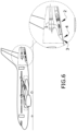
- the free end of the door (4.3) opens towards the first and the second ducts (5, 6), i.e., towards the inside of the tail cone.
- the free end of the door (4.3) is the end of the door (4.3) opposite to its hinge. The free end is movable between:
- first duct (5) and the second duct (6) are separated by a partition wall (9) longitudinal to the first and second duct (5, 6) that splits the air flow downstream of the air inlet (3).
- the shown embodiment of the secondary door (4.2) disclosed in figures 2 to 4 comprises a first portion (4.2.1), see figure 2 , adjacent to the hinge comprising an opening adapted to the cross shape of the second duct (6).
- the secondary door (4.2) comprises a second portion (4.2.2) adjacent to the first portion (4.2.1) adapted to be located against the entrance of the first duct (5) and having no openings. Therefore, when the main door (4.1) is partially opened, the shape of the secondary door (4.2) allows the air flow to go through the second duct (6) but not to the first duct (5).
- the torsion spring (10) pushes the secondary door (4.2) against the entrance of the first duct (5) so that the secondary door (4.2) is kept at its fully closed position while the main door (4.1) is located between the first position and the second position.
- the main door (4.1) comprises a cam (11) configured to push the secondary door (4.2) in the positions ranging between the second and the third position.
- the cam (11) starts to push the secondary door (4.2) at the second position and moves the secondary door (4.2) to its fully open position at the third position while at any position between second and third positions the torsion spring (10) holds the secondary door (4.2) against the cam (11).
- the cam (11) is attached to the main door (4.1) at both lateral sides of the main door (4.1).
- the secondary door (4.2) keeps closed until the main door (4.1) rotates beyond the second position, namely while running from the second position to the third position, the secondary door (4.2) opens and gets at the fully open position, see figure 3 , when the main door (4.1) is at the fully open third position.
- auxiliary power unit (APU) (1) is not required to be ON, but the air turbine (7) helps to provide additional drag to slow down the aircraft and convert the otherwise wasted energy into useful electrical energy by means of the generator coupled to the air turbine (7).
- This position is also used for emergency power generation.
- the electrical energy could be stored for instance on supercapacitors or high charge/discharge rate batteries or used while the air turbine (7) is ON.
- the air turbine (7) is coupled to an alternator that provides electrical energy to the aircraft, it could be stored at supercapacitors, at high charge/discharge rate batteries or feed the aircraft electrical system for instant power use.
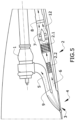
- Figures 1 , 4 and 5 disclose embodiments of the third position of the air inlet door unit (4).
- the second duct (6) comprises a convergent exhaust (12) to the atmosphere downstream the air turbine (7). Therefore, the walls of the second duct (6) tend to approach each other.
- the air turbine (7) comprises variable pitch blades. It allows to trim the pitch at any desired angle and also at least to put the blades at the feathered position, i.e., streamlined with the air flow.
Landscapes
- Engineering & Computer Science (AREA)
- Aviation & Aerospace Engineering (AREA)
- Chemical & Material Sciences (AREA)
- Combustion & Propulsion (AREA)
- Mechanical Engineering (AREA)
- Life Sciences & Earth Sciences (AREA)
- Sustainable Development (AREA)
- Sustainable Energy (AREA)
- General Engineering & Computer Science (AREA)
- Physics & Mathematics (AREA)
- Power Engineering (AREA)
- Thermal Sciences (AREA)
- Connection Of Motors, Electrical Generators, Mechanical Devices, And The Like (AREA)
- Other Liquid Machine Or Engine Such As Wave Power Use (AREA)
Claims (15)
- Hilfstriebwerksystem eines Luftfahrzeugs, das Folgendes umfasst:- ein Hilfstriebwerk (APU) (1),- eine Kühleinheit für das Hilfstriebwerk (APU) (1), die mindestens einen Wärmetauscher (2) umfasst,- einen Lufteinlass (3) in Fluidverbindung mit dem Hilfstriebwerk (APU) (1) und mit der Kühleinheit,- eine Lufteinlassklappeneinheit (4), die sich am Lufteinlass (3) befindet, um ein Eintreten eines Luftstroms von außerhalb des Luftfahrzeugs in den Lufteinlass (3) zu ermöglichen,- einen ersten Kanal (5), der zum Ansaugen von Luft in das Hilfstriebwerk (APU) (1) ausgelegt ist und einen Eingang in Fluidverbindung mit dem Lufteinlass (3) aufweist,- einen zweiten Kanal (6), der einen Eingang in Fluidverbindung mit dem Lufteinlass (3) aufweist, wobei sich der Wärmetauscher (2) zumindest teilweise innerhalb des zweiten Kanals (6) befindet,wobei das Hilfstriebwerksystem dadurch gekennzeichnet ist, dass es Folgendes umfasst:- eine Luftturbine (7), die sich innerhalb des zweiten Kanals (6) stromabwärts des Wärmetauschers (2) befindet, und- einen elektrischen Generator, der mit der Luftturbine (7) gekoppelt ist, so dass die Luftturbine (7) und der elektrische Generator dazu ausgelegt sind, Energie eines Luftstroms in dem zweiten Kanal (6) in elektrische Energie umzuwandeln.
- Hilfstriebwerksystem eines Luftfahrzeugs nach Anspruch 1, wobei die Lufteinlassklappeneinheit (4) zwischen Folgendem beweglich ist:o einer ersten Position, in der sie dazu ausgelegt ist, den Luftstrom zu dem ersten Kanal (5) und zu dem zweiten Kanal (6) zu schließen,o einer zweiten Position, in der sie dazu ausgelegt ist, den Luftstrom zu dem ersten Kanal (5) zu schließen, und sie dazu ausgelegt ist, den Luftstrom zu dem zweiten Kanal (6) zu öffnen, so dass die Luftturbine (7) einen Luftwiderstand des Luftfahrzeugs erhöht und/oder die Luftturbine (7) elektrische Leistung erzeugt, undo einer dritten Position, in der sie dazu ausgelegt ist, den Luftstrom zu dem ersten Kanal (5) und zu dem zweiten Kanal (6) zu öffnen.
- Hilfstriebwerksystem eines Luftfahrzeugs nach einem der vorhergehenden Ansprüche, wobei die Luftturbine (7) Schaufeln mit variabler Steigung umfasst, so dass die Steigung der Schaufeln stromlinienförmig mit dem Luftstrom ausgestaltet werden kann.
- Hilfstriebwerksystem eines Luftfahrzeugs nach einem der vorhergehenden Ansprüche, wobei der zweite Kanal (6) einen konvergenten Auslass (12) umfasst, der sich stromabwärts der Luftturbine (7) befindet.
- Hilfstriebwerksystem eines Luftfahrzeugs nach einem der vorhergehenden Ansprüche, wobei der zweite Kanal (6) einen divergenten Abschnitt stromaufwärts des Wärmetauschers (2.1, 2.2) in nächster Nähe zu dem Eingang des zweiten Kanals (6) umfasst.
- Hilfstriebwerksystem eines Luftfahrzeugs nach einem der vorhergehenden Ansprüche, wobei sich der zweite Kanal (6) in dem Hilfstriebwerksystem in einer Position weiter außen als der erste Kanal (5) befindet.
- Hilfstriebwerksystem eines Luftfahrzeugs nach einem der vorhergehenden Ansprüche, wobei die Kühleinheit einen ersten Wärmetauscher (2.1) und einen zweiten Wärmetauscher (2.2) umfasst, der sich stromaufwärts des ersten Wärmetauschers (2.1) innerhalb des zweiten Kanals (6) befindet.
- Hilfstriebwerksystem eines Luftfahrzeugs nach einem der vorhergehenden Ansprüche, wobei die Lufteinlassklappeneinheit (4) eine Hauptklappe (4.1) und eine Sekundärklappe (4.2) umfasst, die beide mit einem Scharnier an einem hinteren Ende des Lufteinlasses (3) angebracht sind, wobei die Hauptklappe (4.1) dazu ausgelegt ist, den Lufteinlass (3) zu öffnen und zu schließen, und die Sekundärklappe (4.2) dazu ausgelegt ist, den Eingang des ersten Kanals (5) zu öffnen und zu schließen.
- Hilfstriebwerksystem eines Luftfahrzeugs nach Anspruch 8, wobei die Sekundärklappe (4.2) einen an das Scharnier angrenzenden ersten Abschnitt (4.2.1), der eine Öffnung umfasst, die an die Querform des zweiten Kanals (6) angepasst ist, und einen zweiten Abschnitt (4.2.2) umfasst, der an den ersten Abschnitt (4.2.1) angrenzt und so angepasst ist, dass er sich am Eingang des ersten Kanals (5) befindet, und der keine Öffnungen aufweist.
- Hilfstriebwerksystem eines Luftfahrzeugs nach einem der vorhergehenden Ansprüche 8 bis 9, wobei die Hauptklappe (4.1) und die Sekundärklappe (4.2) drehbar verbunden sind und die Eingangsklappeneinheit (4) zudem eine Torsionsfeder (10) umfasst, die sich zwischen der Hauptklappe (4.1) und der Sekundärklappe (4.2) erstreckt, damit die Sekundärklappe (4.2) den ersten Kanal (5) geschlossen hält, wenn sich die Hauptklappe (4.1) in der zweiten Position befindet.
- Hilfstriebwerksystem eines Luftfahrzeugs nach einem der vorhergehenden Ansprüche 8 bis 10, wobei die Hauptklappe (4.1) einen Nocken (11) umfasst, der dazu ausgelegt ist, die Sekundärklappe (4.2) zwischen der zweiten und der dritten Position zu verschieben.
- Hilfstriebwerksystem eines Luftfahrzeugs nach einem der vorhergehenden Ansprüche 1 bis 7, wobei die Lufteinlassklappeneinheit (4) eine Klappe (4.3) umfasst, die mit einem Scharnier an einem vorderen Ende des Lufteinlasses (3) angebracht ist, wobei die Klappe (4.3) ein freies Ende aufweist, das dazu ausgelegt ist, sich in Richtung des ersten und des zweiten Kanals (5, 6) zu öffnen, wobei die Klappe (4.3) zwischen Folgendem beweglich ist:- einer ersten Position, in der sich das freie Ende an einem hinteren Ende des Lufteinlasses (3) befindet, um den Lufteinlass (3) zu schließen,- einer zweiten Position, in der sich das freie Ende an einem Querende des zweiten Kanals (6) gegenüber dem Lufteinlass (3) befindet, um den Eingang des zweiten Kanals (6) zu öffnen, und- einer dritten Position, in der sich das freie Ende an einem Querende des ersten Kanals (5) gegenüber dem zweiten Kanal (6) befindet, um die Eingänge des ersten Kanals (5) und des zweiten Kanals (6) zu öffnen.
- Hilfstriebwerksystem eines Luftfahrzeugs nach einem der vorhergehenden Ansprüche, wobei der erste Kanal (5) und der zweite Kanal (6) durch eine Trennwand (9) längs zu dem ersten und dem zweiten Kanal (5, 6) getrennt und dazu ausgelegt sind, den Luftstrom stromabwärts des Lufteinlasses (3) zu teilen.
- Heckkonus eines Luftfahrzeugs, umfassend ein Hilfstriebwerksystem nach einem der vorhergehenden Ansprüche.
- Luftfahrzeug, umfassend einen Heckkonus nach Anspruch 14.
Priority Applications (4)
| Application Number | Priority Date | Filing Date | Title |
|---|---|---|---|
| EP22382511.8A EP4282765B1 (de) | 2022-05-27 | 2022-05-27 | Hilfstriebwerkssystem eines flugzeugs |
| ES22382511T ES3045612T3 (en) | 2022-05-27 | 2022-05-27 | Auxiliary power unit system of an aircraft |
| CN202310397904.1A CN117125258B (zh) | 2022-05-27 | 2023-04-14 | 飞机辅助动力装置系统 |
| US18/311,331 US12168522B2 (en) | 2022-05-27 | 2023-05-03 | Auxiliary power unit system of an aircraft |
Applications Claiming Priority (1)
| Application Number | Priority Date | Filing Date | Title |
|---|---|---|---|
| EP22382511.8A EP4282765B1 (de) | 2022-05-27 | 2022-05-27 | Hilfstriebwerkssystem eines flugzeugs |
Publications (2)
| Publication Number | Publication Date |
|---|---|
| EP4282765A1 EP4282765A1 (de) | 2023-11-29 |
| EP4282765B1 true EP4282765B1 (de) | 2025-07-02 |
Family
ID=81940395
Family Applications (1)
| Application Number | Title | Priority Date | Filing Date |
|---|---|---|---|
| EP22382511.8A Active EP4282765B1 (de) | 2022-05-27 | 2022-05-27 | Hilfstriebwerkssystem eines flugzeugs |
Country Status (4)
| Country | Link |
|---|---|
| US (1) | US12168522B2 (de) |
| EP (1) | EP4282765B1 (de) |
| CN (1) | CN117125258B (de) |
| ES (1) | ES3045612T3 (de) |
Families Citing this family (3)
| Publication number | Priority date | Publication date | Assignee | Title |
|---|---|---|---|---|
| US12545427B2 (en) | 2023-06-08 | 2026-02-10 | Hamilton Sundstrand Corporation | Ducted supplemental power unit of aircraft |
| CN117302530B (zh) * | 2023-11-30 | 2024-02-23 | 中国航空工业集团公司金城南京机电液压工程研究中心 | 一种冲压空气作为动力源和热沉的电热互补系统 |
| US20260092580A1 (en) * | 2024-09-30 | 2026-04-02 | Hamilton Sundstrand Corporation | Ram air turbine fixed within aircraft |
Family Cites Families (9)
| Publication number | Priority date | Publication date | Assignee | Title |
|---|---|---|---|---|
| US6264137B1 (en) * | 2000-02-25 | 2001-07-24 | Honeywell International Inc. | Inlet vortex bustor and ice protector for auxiliary power units |
| US6651929B2 (en) * | 2001-10-29 | 2003-11-25 | Pratt & Whitney Canada Corp. | Passive cooling system for auxiliary power unit installation |
| US8141816B2 (en) * | 2008-04-30 | 2012-03-27 | Honeywell International Inc. | AFT inlet duct mounted door actuator |
| DE102009010243A1 (de) * | 2009-02-24 | 2010-09-02 | Airbus Deutschland Gmbh | Leistungserzeugungs-Vorrichtung sowie Rumpf-Bauteil mit einer solchen Leistungserzeugungs-Vorrichtung |
| US20120312023A1 (en) * | 2011-06-08 | 2012-12-13 | Honeywell International Inc. | Thermal management systems and methods for auxiliary power units |
| US10240521B2 (en) * | 2015-08-07 | 2019-03-26 | Pratt & Whitney Canada Corp. | Auxiliary power unit with variable speed ratio |
| US10253726B2 (en) * | 2015-08-07 | 2019-04-09 | Pratt & Whitney Canada Corp. | Engine assembly with combined engine and cooling exhaust |
| US20200130858A1 (en) * | 2018-10-29 | 2020-04-30 | Pratt & Whitney Canada Corp. | Method and system for cooling an auxiliary power unit using aircraft fuel |
| US12187443B2 (en) * | 2020-02-14 | 2025-01-07 | Bombardier Inc. | Excess thrust control for an aircraft |
-
2022
- 2022-05-27 EP EP22382511.8A patent/EP4282765B1/de active Active
- 2022-05-27 ES ES22382511T patent/ES3045612T3/es active Active
-
2023
- 2023-04-14 CN CN202310397904.1A patent/CN117125258B/zh active Active
- 2023-05-03 US US18/311,331 patent/US12168522B2/en active Active
Also Published As
| Publication number | Publication date |
|---|---|
| CN117125258B (zh) | 2026-01-23 |
| EP4282765A1 (de) | 2023-11-29 |
| US20230382553A1 (en) | 2023-11-30 |
| ES3045612T3 (en) | 2025-11-28 |
| CN117125258A (zh) | 2023-11-28 |
| US12168522B2 (en) | 2024-12-17 |
Similar Documents
| Publication | Publication Date | Title |
|---|---|---|
| US11685542B2 (en) | Propulsion engine for an aircraft | |
| US12168522B2 (en) | Auxiliary power unit system of an aircraft | |
| CN102695862B (zh) | 涡轮发动机推进单元的流体冷却装置 | |
| EP3483414B1 (de) | Gasturbinentriebwerk mit einem luft-öl-wärmetauscher | |
| US10800539B2 (en) | Propulsion engine for an aircraft | |
| EP3179074B1 (de) | Wärmeverwaltungssystem | |
| EP1944475B1 (de) | Wärmeaustauschsystem | |
| US8876465B2 (en) | Gas turbine engine | |
| US20110179767A1 (en) | Cooling device for aircraft propeller | |
| US10883422B2 (en) | Cooling device for a turbomachine supplied by a discharge circuit | |
| US8161726B2 (en) | Cooling exchanger duct | |
| EP2066890B1 (de) | Modulationsströmung durch turbomotorkühlsystem | |
| EP2971664B1 (de) | Getriebeturbofanmotor und kühlverfahren dafür | |
| EP1882824A2 (de) | Doppelter Einlasskanal eines Schmiermittelkühltauschers | |
| JPH04219422A (ja) | 航空機エンジンスタータと一体化した境界抽気系統 | |
| US11674438B1 (en) | Thermal management system | |
| EP3647564B1 (de) | Kühlung von anbaugeräten eines gasturbinenmotors | |
| US20110182723A1 (en) | Turbomachine aircraft propeller | |
| US20230286658A1 (en) | Ram-air duct system | |
| US20250154878A1 (en) | Nose cone heat exchanger cooling airflow on open-rotor gas turbine engine |
Legal Events
| Date | Code | Title | Description |
|---|---|---|---|
| PUAI | Public reference made under article 153(3) epc to a published international application that has entered the european phase |
Free format text: ORIGINAL CODE: 0009012 |
|
| STAA | Information on the status of an ep patent application or granted ep patent |
Free format text: STATUS: THE APPLICATION HAS BEEN PUBLISHED |
|
| AK | Designated contracting states |
Kind code of ref document: A1 Designated state(s): AL AT BE BG CH CY CZ DE DK EE ES FI FR GB GR HR HU IE IS IT LI LT LU LV MC MK MT NL NO PL PT RO RS SE SI SK SM TR |
|
| STAA | Information on the status of an ep patent application or granted ep patent |
Free format text: STATUS: REQUEST FOR EXAMINATION WAS MADE |
|
| 17P | Request for examination filed |
Effective date: 20240520 |
|
| RBV | Designated contracting states (corrected) |
Designated state(s): AL AT BE BG CH CY CZ DE DK EE ES FI FR GB GR HR HU IE IS IT LI LT LU LV MC MK MT NL NO PL PT RO RS SE SI SK SM TR |
|
| GRAP | Despatch of communication of intention to grant a patent |
Free format text: ORIGINAL CODE: EPIDOSNIGR1 |
|
| STAA | Information on the status of an ep patent application or granted ep patent |
Free format text: STATUS: GRANT OF PATENT IS INTENDED |
|
| RIC1 | Information provided on ipc code assigned before grant |
Ipc: B64D 41/00 20060101AFI20250220BHEP |
|
| INTG | Intention to grant announced |
Effective date: 20250228 |
|
| GRAS | Grant fee paid |
Free format text: ORIGINAL CODE: EPIDOSNIGR3 |
|
| GRAA | (expected) grant |
Free format text: ORIGINAL CODE: 0009210 |
|
| STAA | Information on the status of an ep patent application or granted ep patent |
Free format text: STATUS: THE PATENT HAS BEEN GRANTED |
|
| AK | Designated contracting states |
Kind code of ref document: B1 Designated state(s): AL AT BE BG CH CY CZ DE DK EE ES FI FR GB GR HR HU IE IS IT LI LT LU LV MC MK MT NL NO PL PT RO RS SE SI SK SM TR |
|
| REG | Reference to a national code |
Ref country code: GB Ref legal event code: FG4D |
|
| REG | Reference to a national code |
Ref country code: CH Ref legal event code: EP |
|
| REG | Reference to a national code |
Ref country code: DE Ref legal event code: R096 Ref document number: 602022016844 Country of ref document: DE |
|
| REG | Reference to a national code |
Ref country code: IE Ref legal event code: FG4D |
|
| REG | Reference to a national code |
Ref country code: NL Ref legal event code: MP Effective date: 20250702 |
|
| REG | Reference to a national code |
Ref country code: ES Ref legal event code: FG2A Ref document number: 3045612 Country of ref document: ES Kind code of ref document: T3 Effective date: 20251128 |
|
| PG25 | Lapsed in a contracting state [announced via postgrant information from national office to epo] |
Ref country code: PT Free format text: LAPSE BECAUSE OF FAILURE TO SUBMIT A TRANSLATION OF THE DESCRIPTION OR TO PAY THE FEE WITHIN THE PRESCRIBED TIME-LIMIT Effective date: 20251103 |
|
| PG25 | Lapsed in a contracting state [announced via postgrant information from national office to epo] |
Ref country code: NL Free format text: LAPSE BECAUSE OF FAILURE TO SUBMIT A TRANSLATION OF THE DESCRIPTION OR TO PAY THE FEE WITHIN THE PRESCRIBED TIME-LIMIT Effective date: 20250702 |
|
| REG | Reference to a national code |
Ref country code: AT Ref legal event code: MK05 Ref document number: 1809004 Country of ref document: AT Kind code of ref document: T Effective date: 20250702 |
|
| PG25 | Lapsed in a contracting state [announced via postgrant information from national office to epo] |
Ref country code: IS Free format text: LAPSE BECAUSE OF FAILURE TO SUBMIT A TRANSLATION OF THE DESCRIPTION OR TO PAY THE FEE WITHIN THE PRESCRIBED TIME-LIMIT Effective date: 20251102 |
|
| PG25 | Lapsed in a contracting state [announced via postgrant information from national office to epo] |
Ref country code: NO Free format text: LAPSE BECAUSE OF FAILURE TO SUBMIT A TRANSLATION OF THE DESCRIPTION OR TO PAY THE FEE WITHIN THE PRESCRIBED TIME-LIMIT Effective date: 20251002 |
|
| REG | Reference to a national code |
Ref country code: LT Ref legal event code: MG9D |
|
| PG25 | Lapsed in a contracting state [announced via postgrant information from national office to epo] |
Ref country code: AT Free format text: LAPSE BECAUSE OF FAILURE TO SUBMIT A TRANSLATION OF THE DESCRIPTION OR TO PAY THE FEE WITHIN THE PRESCRIBED TIME-LIMIT Effective date: 20250702 |
|
| PG25 | Lapsed in a contracting state [announced via postgrant information from national office to epo] |
Ref country code: FI Free format text: LAPSE BECAUSE OF FAILURE TO SUBMIT A TRANSLATION OF THE DESCRIPTION OR TO PAY THE FEE WITHIN THE PRESCRIBED TIME-LIMIT Effective date: 20250702 |
|
| PG25 | Lapsed in a contracting state [announced via postgrant information from national office to epo] |
Ref country code: HR Free format text: LAPSE BECAUSE OF FAILURE TO SUBMIT A TRANSLATION OF THE DESCRIPTION OR TO PAY THE FEE WITHIN THE PRESCRIBED TIME-LIMIT Effective date: 20250702 |
|
| PG25 | Lapsed in a contracting state [announced via postgrant information from national office to epo] |
Ref country code: GR Free format text: LAPSE BECAUSE OF FAILURE TO SUBMIT A TRANSLATION OF THE DESCRIPTION OR TO PAY THE FEE WITHIN THE PRESCRIBED TIME-LIMIT Effective date: 20251003 |
|
| PG25 | Lapsed in a contracting state [announced via postgrant information from national office to epo] |
Ref country code: SE Free format text: LAPSE BECAUSE OF FAILURE TO SUBMIT A TRANSLATION OF THE DESCRIPTION OR TO PAY THE FEE WITHIN THE PRESCRIBED TIME-LIMIT Effective date: 20250702 Ref country code: CZ Free format text: LAPSE BECAUSE OF FAILURE TO SUBMIT A TRANSLATION OF THE DESCRIPTION OR TO PAY THE FEE WITHIN THE PRESCRIBED TIME-LIMIT Effective date: 20250702 |
|
| PG25 | Lapsed in a contracting state [announced via postgrant information from national office to epo] |
Ref country code: LV Free format text: LAPSE BECAUSE OF FAILURE TO SUBMIT A TRANSLATION OF THE DESCRIPTION OR TO PAY THE FEE WITHIN THE PRESCRIBED TIME-LIMIT Effective date: 20250702 |
|
| PG25 | Lapsed in a contracting state [announced via postgrant information from national office to epo] |
Ref country code: PL Free format text: LAPSE BECAUSE OF FAILURE TO SUBMIT A TRANSLATION OF THE DESCRIPTION OR TO PAY THE FEE WITHIN THE PRESCRIBED TIME-LIMIT Effective date: 20250702 Ref country code: BG Free format text: LAPSE BECAUSE OF FAILURE TO SUBMIT A TRANSLATION OF THE DESCRIPTION OR TO PAY THE FEE WITHIN THE PRESCRIBED TIME-LIMIT Effective date: 20250702 |
|
| PG25 | Lapsed in a contracting state [announced via postgrant information from national office to epo] |
Ref country code: RS Free format text: LAPSE BECAUSE OF FAILURE TO SUBMIT A TRANSLATION OF THE DESCRIPTION OR TO PAY THE FEE WITHIN THE PRESCRIBED TIME-LIMIT Effective date: 20251002 |
|
| PG25 | Lapsed in a contracting state [announced via postgrant information from national office to epo] |
Ref country code: SM Free format text: LAPSE BECAUSE OF FAILURE TO SUBMIT A TRANSLATION OF THE DESCRIPTION OR TO PAY THE FEE WITHIN THE PRESCRIBED TIME-LIMIT Effective date: 20250702 |
|
| PG25 | Lapsed in a contracting state [announced via postgrant information from national office to epo] |
Ref country code: DK Free format text: LAPSE BECAUSE OF FAILURE TO SUBMIT A TRANSLATION OF THE DESCRIPTION OR TO PAY THE FEE WITHIN THE PRESCRIBED TIME-LIMIT Effective date: 20250702 |
|
| PG25 | Lapsed in a contracting state [announced via postgrant information from national office to epo] |
Ref country code: IT Free format text: LAPSE BECAUSE OF FAILURE TO SUBMIT A TRANSLATION OF THE DESCRIPTION OR TO PAY THE FEE WITHIN THE PRESCRIBED TIME-LIMIT Effective date: 20250702 |