EP4282686A1 - Mobile screen device and vehicle - Google Patents
Mobile screen device and vehicle Download PDFInfo
- Publication number
- EP4282686A1 EP4282686A1 EP21920300.7A EP21920300A EP4282686A1 EP 4282686 A1 EP4282686 A1 EP 4282686A1 EP 21920300 A EP21920300 A EP 21920300A EP 4282686 A1 EP4282686 A1 EP 4282686A1
- Authority
- EP
- European Patent Office
- Prior art keywords
- assembly
- sliding
- screen device
- sliding rail
- rotating member
- Prior art date
- Legal status (The legal status is an assumption and is not a legal conclusion. Google has not performed a legal analysis and makes no representation as to the accuracy of the status listed.)
- Withdrawn
Links
Images


Classifications
-
- B—PERFORMING OPERATIONS; TRANSPORTING
- B60—VEHICLES IN GENERAL
- B60R—VEHICLES, VEHICLE FITTINGS, OR VEHICLE PARTS, NOT OTHERWISE PROVIDED FOR
- B60R11/00—Arrangements for holding or mounting articles, not otherwise provided for
- B60R11/02—Arrangements for holding or mounting articles, not otherwise provided for for radio sets, television sets, telephones, or the like; Arrangement of controls thereof
- B60R11/0229—Arrangements for holding or mounting articles, not otherwise provided for for radio sets, television sets, telephones, or the like; Arrangement of controls thereof for displays, e.g. cathodic tubes
- B60R11/0235—Arrangements for holding or mounting articles, not otherwise provided for for radio sets, television sets, telephones, or the like; Arrangement of controls thereof for displays, e.g. cathodic tubes of flat type, e.g. LCD
-
- B—PERFORMING OPERATIONS; TRANSPORTING
- B60—VEHICLES IN GENERAL
- B60K—ARRANGEMENT OR MOUNTING OF PROPULSION UNITS OR OF TRANSMISSIONS IN VEHICLES; ARRANGEMENT OR MOUNTING OF PLURAL DIVERSE PRIME-MOVERS IN VEHICLES; AUXILIARY DRIVES FOR VEHICLES; INSTRUMENTATION OR DASHBOARDS FOR VEHICLES; ARRANGEMENTS IN CONNECTION WITH COOLING, AIR INTAKE, GAS EXHAUST OR FUEL SUPPLY OF PROPULSION UNITS IN VEHICLES
- B60K35/00—Instruments specially adapted for vehicles; Arrangement of instruments in or on vehicles
- B60K35/20—Output arrangements, i.e. from vehicle to user, associated with vehicle functions or specially adapted therefor
- B60K35/21—Output arrangements, i.e. from vehicle to user, associated with vehicle functions or specially adapted therefor using visual output, e.g. blinking lights or matrix displays
- B60K35/22—Display screens
-
- B—PERFORMING OPERATIONS; TRANSPORTING
- B60—VEHICLES IN GENERAL
- B60K—ARRANGEMENT OR MOUNTING OF PROPULSION UNITS OR OF TRANSMISSIONS IN VEHICLES; ARRANGEMENT OR MOUNTING OF PLURAL DIVERSE PRIME-MOVERS IN VEHICLES; AUXILIARY DRIVES FOR VEHICLES; INSTRUMENTATION OR DASHBOARDS FOR VEHICLES; ARRANGEMENTS IN CONNECTION WITH COOLING, AIR INTAKE, GAS EXHAUST OR FUEL SUPPLY OF PROPULSION UNITS IN VEHICLES
- B60K35/00—Instruments specially adapted for vehicles; Arrangement of instruments in or on vehicles
-
- B—PERFORMING OPERATIONS; TRANSPORTING
- B60—VEHICLES IN GENERAL
- B60K—ARRANGEMENT OR MOUNTING OF PROPULSION UNITS OR OF TRANSMISSIONS IN VEHICLES; ARRANGEMENT OR MOUNTING OF PLURAL DIVERSE PRIME-MOVERS IN VEHICLES; AUXILIARY DRIVES FOR VEHICLES; INSTRUMENTATION OR DASHBOARDS FOR VEHICLES; ARRANGEMENTS IN CONNECTION WITH COOLING, AIR INTAKE, GAS EXHAUST OR FUEL SUPPLY OF PROPULSION UNITS IN VEHICLES
- B60K35/00—Instruments specially adapted for vehicles; Arrangement of instruments in or on vehicles
- B60K35/20—Output arrangements, i.e. from vehicle to user, associated with vehicle functions or specially adapted therefor
-
- B—PERFORMING OPERATIONS; TRANSPORTING
- B60—VEHICLES IN GENERAL
- B60K—ARRANGEMENT OR MOUNTING OF PROPULSION UNITS OR OF TRANSMISSIONS IN VEHICLES; ARRANGEMENT OR MOUNTING OF PLURAL DIVERSE PRIME-MOVERS IN VEHICLES; AUXILIARY DRIVES FOR VEHICLES; INSTRUMENTATION OR DASHBOARDS FOR VEHICLES; ARRANGEMENTS IN CONNECTION WITH COOLING, AIR INTAKE, GAS EXHAUST OR FUEL SUPPLY OF PROPULSION UNITS IN VEHICLES
- B60K35/00—Instruments specially adapted for vehicles; Arrangement of instruments in or on vehicles
- B60K35/50—Instruments characterised by their means of attachment to or integration in the vehicle
- B60K35/53—Movable instruments, e.g. slidable
-
- B—PERFORMING OPERATIONS; TRANSPORTING
- B60—VEHICLES IN GENERAL
- B60K—ARRANGEMENT OR MOUNTING OF PROPULSION UNITS OR OF TRANSMISSIONS IN VEHICLES; ARRANGEMENT OR MOUNTING OF PLURAL DIVERSE PRIME-MOVERS IN VEHICLES; AUXILIARY DRIVES FOR VEHICLES; INSTRUMENTATION OR DASHBOARDS FOR VEHICLES; ARRANGEMENTS IN CONNECTION WITH COOLING, AIR INTAKE, GAS EXHAUST OR FUEL SUPPLY OF PROPULSION UNITS IN VEHICLES
- B60K35/00—Instruments specially adapted for vehicles; Arrangement of instruments in or on vehicles
- B60K35/60—Instruments characterised by their location or relative disposition in or on vehicles
-
- B—PERFORMING OPERATIONS; TRANSPORTING
- B60—VEHICLES IN GENERAL
- B60R—VEHICLES, VEHICLE FITTINGS, OR VEHICLE PARTS, NOT OTHERWISE PROVIDED FOR
- B60R11/00—Arrangements for holding or mounting articles, not otherwise provided for
- B60R2011/0042—Arrangements for holding or mounting articles, not otherwise provided for characterised by mounting means
- B60R2011/008—Adjustable or movable supports
- B60R2011/0084—Adjustable or movable supports with adjustment by linear movement in their operational position
-
- B—PERFORMING OPERATIONS; TRANSPORTING
- B60—VEHICLES IN GENERAL
- B60R—VEHICLES, VEHICLE FITTINGS, OR VEHICLE PARTS, NOT OTHERWISE PROVIDED FOR
- B60R11/00—Arrangements for holding or mounting articles, not otherwise provided for
- B60R2011/0042—Arrangements for holding or mounting articles, not otherwise provided for characterised by mounting means
- B60R2011/008—Adjustable or movable supports
- B60R2011/0092—Adjustable or movable supports with motorization
-
- B—PERFORMING OPERATIONS; TRANSPORTING
- B62—LAND VEHICLES FOR TRAVELLING OTHERWISE THAN ON RAILS
- B62D—MOTOR VEHICLES; TRAILERS
- B62D25/00—Superstructure or monocoque structure sub-units; Parts or details thereof not otherwise provided for
- B62D25/08—Front or rear portions
- B62D25/14—Dashboards as superstructure sub-units
Definitions
- the present application relates to the technical field of automotive technology, in particular to a mobile screen device and a vehicle.
- Automotive display screens are previously only available in high-end or high-configuration models, but now they can be seen in small cars including A00 and A0 levels, as well as A-level economy sedans.
- the automotive display screen can not only display a portion of the data of the driving computer through screen display, but also play programs and add many entertainment functions.
- the existing dashboard display screen can even display navigation, tire pressure monitoring and other information in some models.
- the combination of functions is rich and partially overlaps with the functions of the central control display screen, resulting in the redistribution and design of functions between the two.
- the increase in functionality also makes the central control display screen become wider, resulting in difficulty in layout. Furthermore, after installing and sliding the existing display screen according to the requirements, the gaps on both sides of the display screen cannot be blocked after moving left and right, and the internal structure of the display screen is visible on the appearance, which cannot meet the product appearance requirements.
- the present application provides a mobile screen device and a vehicle.
- the present application is provided with a shielding assembly to shield the sliding assembly to avoid the internal structure of the sliding assembly from being seen from the outside, making the mobile screen device more aesthetically pleasing. Further, the roller shutter door and the sliding member share the same sliding rail, making the overall size smaller.
- the present application provides a mobile screen device including a screen assembly, a driving assembly, a sliding assembly, and a shielding assembly for shielding the sliding assembly;
- the shielding assembly includes a roller shutter door and a plurality of guide wheels; the plurality of the guide wheels are arranged on the same side of the roller shutter door, and the guide wheels are arranged in the sliding rail.
- roller shutter door is provided with a first mounting hole matching the sliding member, and the sliding member is arranged in the first mounting hole.
- a length of the roller shutter door is less than a perimeter of the sliding rail.
- the sliding rail includes a first limiting slot and a second limiting slot which are oppositely arranged; one edge of the roller shutter door with the guide wheels is arranged in the first limiting slot, and the other edge of the roller shutter door is arranged in the second limiting slot, such that the roller shutter door can slide along the sliding rail.
- the distance between the first limiting slot and the second limiting slot is a first distance
- the height of the shielding assembly is a second distance
- the first distance is not less than the second distance
- the sliding assembly further includes a mounting member, one end of the mounting member is connected to the sliding rail, and the other end of the mounting member is configured to connect to a surface to be installed.
- a limiting structure is provided on the sliding rail, the limiting structure is configured to limit the movement of the rotating member along its axial direction, the limiting structure abuts against two ends of the rotating member, and the rotating member can rotate relative to the limiting structure.
- the rotating member is arranged along the length direction of the sliding rail, and the length of the rotating member is less than the length of the sliding rail.
- the driving assembly includes a motor and a driving member, the motor is fixed on the sliding rail, one end of the driving member is connected to the motor, and the other end of the driving member is connected to the rotating member, such that the motor can drive the rotating member to rotate.
- the driving member is a conveyor belt, a conveyor chain, or a gear.
- the sliding rail is a C-shaped structure with openings at two ends; the two ends of the sliding rail are each provided with a first mounting bracket for limiting the position of the shielding assembly, and the first mounting bracket can abut against the shielding assembly.
- first mounting bracket is provided with a second mounting hole, and a connecting member is arranged in the second mounting hole;
- the sliding rail is provided with a third mounting hole, and the connecting member passes through the second mounting hole and the third mounting hole in sequence, such that the first mounting bracket is detachably connected to the sliding rail.
- the number of the second mounting hole corresponds to the number of the third mounting hole
- the position of the second mounting hole corresponds to the position of the third mounting hole
- the rotating member is a lead screw
- the sliding member is a nut
- the nut is threadedly connected to the lead screw
- the screen assembly is fixedly connected to the nut.
- the number of the sliding member is two, and the two sliding members are each connected to the rotating member and the screen assembly.
- the screen assembly includes a screen and a second mounting bracket, one end of the second mounting bracket is connected to the screen, and the other end of the second mounting bracket is connected to the sliding member.
- the present application further provides a vehicle including a dashboard and a mobile screen device as described above, wherein the mobile screen device is arranged on the dashboard.
- the existing technology has the following shortcomings: in addition to displaying vehicle driving information, the existing dashboard display screen can even display navigation, tire pressure monitoring and other information in some models.
- the combination of functions is rich and partially overlaps with the functions of the central control display screen, resulting in the redistribution and design of functions between the two.
- the increase in functionality also makes the central control display screen become wider, resulting in difficulty in layout.
- the gaps on both sides of the display screen cannot be blocked after moving left and right, and the internal structure of the display screen is visible on the appearance, which cannot meet the product appearance requirements
- the present application is provided with a shielding assembly to shield the sliding assembly to avoid the internal structure of the sliding assembly from being seen from the outside, making the mobile screen device more aesthetically pleasing. Furthermore, the roller shutter door and the sliding member share the same sliding rail, making the overall size smaller. Moreover, the present application can clamp the roller shutter door by setting the first limiting slot and the second limiting slot, so as to prevent the roller shutter door from falling off and improve the safety performance of the mobile screen device.
- this embodiment provides a mobile screen device and a vehicle.
- the mobile screen device includes a screen assembly 1, a driving assembly 2, a sliding assembly 3, and a shielding assembly 4 for shielding the sliding assembly 3.
- the sliding assembly 3 includes a sliding rail 31, a rotating member 32, and a sliding member 33.
- the rotating member 32 is connected to the sliding member 33.
- the sliding member 33 is respectively connected to the screen assembly 1 and the shielding assembly 4.
- the driving assembly 2 is connected to the rotating member 32.
- the driving assembly 2 is used to drive the rotating member 32 to rotate.
- the shielding assembly 4 is arranged in the sliding rail 31.
- the sliding member 33 can drive the shielding assembly 4 and the screen assembly 1 to slide along the sliding rail 31 under the driving of the rotating member 32.
- the present application is provided with the shielding assembly 4 to shield the sliding assembly 3, thereby avoiding the internal structure of the sliding assembly 3 from being visible from the outside, making the mobile screen device more aesthetically pleasing, wherein the shielding assembly 4 and the screen assembly 1 move synchronously under the drive of the driving assembly 2.
- the shielding assembly 4 includes a roller shutter door 41 and a plurality of guide wheels.
- the plurality of guide wheels are arranged on the same side of the roller shutter door 41, and the guide wheels are arranged in the sliding rail 31.
- one end of the guide wheel is fixed on the roller shutter door 41, and the other end of the guide wheel slides along the sliding rail 31.
- the shielding assembly 4 only includes the roller shutter door 41, and does not include the guide wheels.
- the roller shutter door 41 includes a first edge and a second edge which are oppositely arranged. The first edge is engaged in a first limiting slot 311, and the second edge is engaged in a second limiting slot 312.
- the roller shutter door 41 can slide along the sliding rail 31 under the drive of the driving assembly 2, such that the roller shutter door 41 can shield the interior of the sliding assembly 3, thus making the mobile screen device more aesthetically pleasing.
- roller shutter door 41 can be attached with appearance color texture to achieve decorative effect and make the mobile screen device more aesthetically pleasing.
- the roller shutter door 41 is provided with a first mounting hole matching the sliding member 33, and the sliding member 33 is arranged in the first mounting hole.
- the number of the first mounting hole is one, and the size of the first mounting hole is larger than the size of the sliding member 33.
- Two sliding members 33 are arranged in the first mounting hole, and one end of the sliding member 33 passes through the first mounting hole and is connected to a second mounting bracket.
- the number of the first mounting hole is equal to the number of the sliding member 33, and the shape of the first mounting hole is the same as the shape of the sliding member 33, and the dimensions of the two are equal, such that the sliding member 33 is fully embedded in the first mounting hole, thereby improving the connection stability of the two.
- the length of the roller shutter door 41 is less than the perimeter of the sliding rail 31.
- the original length of the roller shutter door 41 when unfolded is less than the perimeter of the sliding rail 31, such that the roller shutter door 41 can move along the sliding rail 31 with the screen assembly 1, and meet the required moving distance of the screen assembly 1.
- the sliding rail 31 includes a first limiting slot 311 and a second limiting slot 312 which are oppositely arranged.
- roller shutter door 41 One edge of the roller shutter door 41 provided with the guide wheels is arranged in the first limiting slot 311, and the other edge of the roller shutter door 41 is arranged in the second limiting slot 312, such that the roller shutter door 41 can slide along the sliding rail 31.
- one edge of the roller shutter door 41 provided with the guide wheels is engaged in the first limiting slot 311, and the other edge of the roller shutter door 41 is engaged in the second limiting slot 312, so as to prevent the roller shutter door 41 from falling off from the sliding rail 31 and improve the connection stability of the overall structure.
- two opposite edges of the roller shutter door 41 are each provided with the guide wheels, and the guide wheels at the two edges are respectively arranged in the first limiting slot 311 and the second limiting slot 312, such that the roller shutter door 41 can move more smoothly.
- the distance between the first limiting slot 311 and the second limiting slot 312 is a first distance
- the height of the shielding assembly 4 is a second distance
- the first distance is not less than the second distance
- the height of the roller shutter door 41 is less than the first distance, and the sum of the height of the roller shutter door 41 and the height of the guide wheel is still less than the first distance.
- the depth of the second limiting slot 311 is greater than the height of the guide wheel, making the clamping surface of the roller shutter door 41 and the sliding rail 31 larger, thereby improving the connection stability of the two.
- the sliding assembly 3 further includes a mounting member 35, one end of the mounting member 35 is connected to the sliding rail 31, and the other end of the mounting member 35 is used to connect to the surface to be installed.
- the number of the mounting member 35 is multiple, and the specific number of the mounting member 35 is set according to the actual requirements.
- the number of the mounting member 35 is eight, and there are four mounting members 35 on both sides of the sliding rail 31, and the eight mounting members 35 are symmetrically arranged.
- a limiting structure is provided on the sliding rail 31, and the limiting structure is used to limit the movement of the rotating member 32 along its axial direction.
- the limiting structure abuts against two ends of the rotating member 32, and the rotating member 32 can rotate relative to the limiting structure.
- the sliding rail 31 includes two opposite limiting structures, and each of the limiting structures is provided with a third limiting slot.
- One end of the rotating member 31 is arranged in one of the third limiting slots, and the other end of the rotating member 31 is arranged in the other one of the third limiting slots.
- the two ends of the rotating member 31 are respectively in contact with the bottom of the two third limiting slots.
- the rotating member 32 is arranged along the length direction of the sliding rail 31, and the length of the rotating member 32 is smaller than the length of the sliding rail 31.
- the length of the rotating member 32 is required to be set according to the movement range of the screen assembly 1.
- the length of the rotating member 32 can be set to be equal to the length of the sliding rail 31.
- the driving assembly 2 includes a motor 21 and a driving member 22.
- the motor 21 is fixed on the sliding rail 31.
- One end of the driving member 22 is connected to the motor 21, and the other end of the driving member 22 is connected to the rotating member 32, such that the motor 21 can drive the rotating member 32 to rotate.
- the motor 21 includes an output shaft.
- the driving member 22 is respectively connected to the output shaft and the rotating member 32, such that the motor 21 transmits power to the rotating member 32 through the driving member 22, causing the rotating member 32 to rotate, driving the sliding member 33 to move along the axial direction of the rotating member 32, thereby driving the screen assembly 1 and the shielding assembly 4 to move.
- the driving member 22 is a conveyor belt, a conveyor chain, or a gear.
- the rotating member 32 is provided with a first pulley
- the output shaft of the motor 21 is provided with a second pulley
- the conveyor belt is sleeved on the first pulley and the second pulley, and the conveyor belt transmits the power of the motor 21 to the rotating member 32.
- the sliding rail 31 is a C-shaped structure with openings at two ends.
- the two ends of the sliding rail 31 are each provided with a first mounting bracket 34 for limiting the position of the shielding assembly 4, and the first mounting bracket 34 can abut against the shielding assembly 4.
- the openings at the two ends of the sliding rail 31 can facilitate the installation of the shielding assembly 4, and the shielding assembly 4 can be installed into the sliding rail 31 from the opening at one end of the sliding rail 31.
- the first mounting bracket 34 is provided with a second mounting hole, and a connecting member is arranged in the second mounting hole.
- the sliding rail 31 is provided with a third mounting hole.
- the connecting member passes through the second mounting hole and the third mounting hole in sequence, such that the first mounting bracket 34 is detachably connected to the sliding rail 31.
- the shape of the first mounting bracket 34 is adapted to the shape of the open end of the sliding rail 31.
- the number of the second mounting hole corresponds to the number of the third mounting hole
- the position of the second mounting hole corresponds to the position of the third mounting hole
- one of the first mounting brackets 34 is fixedly connected to the sliding rail 31, and the other one of the first mounting brackets 34 is detachably connected to the sliding rail 31.
- the rotating member 32 is a lead screw
- the sliding member 33 is a nut
- the nut is threadedly connected to the lead screw.
- the screen assembly 1 is fixedly connected to the nut.
- the number of the sliding member 33 is two, and the two sliding members 33 are each connected to the rotating member 32 and the screen assembly 1.
- the number of the sliding member 33 is one, one end of the sliding member 33 is connected to the rotating member 32, and the other end of the sliding member 33 is connected to the screen assembly 1.
- the screen assembly 1 includes a screen 11 and a second mounting bracket 12. One end of the second mounting bracket 12 is connected to the screen 11, and the other end of the second mounting bracket 12 is connected to the sliding member 33.
- the second mounting bracket 12 is detachably connected to the screen 11.
- the screen 11 is provided with a first clamping portion
- the second mounting bracket 12 is provided with a second clamping portion.
- the screen 11 and the second mounting bracket 12 are clamped through the first clamping portion and the second clamping portion, making the screen 11 and the second mounting bracket 12 detachably connected.
- the screen 11 is provided with a first threaded hole
- the second mounting bracket 12 is provided with a second threaded hole that matches the first threaded hole.
- a bolt is arranged inside the second threaded hole, and the screen 11 and the second mounting bracket 12 are connected through the bolt.
- the use process of the mobile screen device is as follows: when the screen 11 needs to be moved, the motor 21 is controlled to rotate, thereby driving the rotating member 32 to rotate, and causing the sliding member 33 to move along the axial direction of the rotating member 32.
- the sliding member 33 drives the roller shutter door 41 and the screen assembly 1 to move together along the axial direction of the rotating member 32.
- the present application further provides a vehicle, which includes a dashboard and a mobile screen device as described above.
- the mobile screen device is arranged on the dashboard.
Landscapes
- Engineering & Computer Science (AREA)
- Mechanical Engineering (AREA)
- Chemical & Material Sciences (AREA)
- Combustion & Propulsion (AREA)
- Transportation (AREA)
- Power-Operated Mechanisms For Wings (AREA)
- Fittings On The Vehicle Exterior For Carrying Loads, And Devices For Holding Or Mounting Articles (AREA)
Abstract
Description
- The present application relates to the technical field of automotive technology, in particular to a mobile screen device and a vehicle.
- With the rapid development of automobiles, there are more and more applications of automotive display screens. Automotive display screens are previously only available in high-end or high-configuration models, but now they can be seen in small cars including A00 and A0 levels, as well as A-level economy sedans. The automotive display screen can not only display a portion of the data of the driving computer through screen display, but also play programs and add many entertainment functions.
- In addition to displaying vehicle driving information, the existing dashboard display screen can even display navigation, tire pressure monitoring and other information in some models. The combination of functions is rich and partially overlaps with the functions of the central control display screen, resulting in the redistribution and design of functions between the two. The increase in functionality also makes the central control display screen become wider, resulting in difficulty in layout. Furthermore, after installing and sliding the existing display screen according to the requirements, the gaps on both sides of the display screen cannot be blocked after moving left and right, and the internal structure of the display screen is visible on the appearance, which cannot meet the product appearance requirements.
- Based on the shortcomings of the existing technology, there is an urgent need to research a mobile screen device and a vehicle to solve the above problems.
- In order to solve the above technical problems, the present application provides a mobile screen device and a vehicle. The present application is provided with a shielding assembly to shield the sliding assembly to avoid the internal structure of the sliding assembly from being seen from the outside, making the mobile screen device more aesthetically pleasing. Further, the roller shutter door and the sliding member share the same sliding rail, making the overall size smaller.
- The present application provides a mobile screen device including a screen assembly, a driving assembly, a sliding assembly, and a shielding assembly for shielding the sliding assembly;
- the sliding assembly includes a sliding rail, a rotating member and a sliding member; the rotating member is connected to the sliding member, the sliding member is respectively connected to the screen assembly and the shielding assembly;
- the driving assembly is connected to the rotating member, and the driving assembly is configured to drive the rotating member to rotate;
- the shielding assembly is arranged in the sliding rail, and the sliding member is driven by the rotating member to move such that the sliding member drives the shielding assembly and the screen assembly to slide along the sliding rail.
- Further, the shielding assembly includes a roller shutter door and a plurality of guide wheels;
the plurality of the guide wheels are arranged on the same side of the roller shutter door, and the guide wheels are arranged in the sliding rail. - Further, the roller shutter door is provided with a first mounting hole matching the sliding member, and the sliding member is arranged in the first mounting hole.
- Further, a length of the roller shutter door is less than a perimeter of the sliding rail.
- Further, the sliding rail includes a first limiting slot and a second limiting slot which are oppositely arranged;
one edge of the roller shutter door with the guide wheels is arranged in the first limiting slot, and the other edge of the roller shutter door is arranged in the second limiting slot, such that the roller shutter door can slide along the sliding rail. - Further, the distance between the first limiting slot and the second limiting slot is a first distance, the height of the shielding assembly is a second distance, and the first distance is not less than the second distance.
- Further, the sliding assembly further includes a mounting member, one end of the mounting member is connected to the sliding rail, and the other end of the mounting member is configured to connect to a surface to be installed.
- Further, a limiting structure is provided on the sliding rail, the limiting structure is configured to limit the movement of the rotating member along its axial direction, the limiting structure abuts against two ends of the rotating member, and the rotating member can rotate relative to the limiting structure.
- Further, the rotating member is arranged along the length direction of the sliding rail, and the length of the rotating member is less than the length of the sliding rail.
- Further, the driving assembly includes a motor and a driving member, the motor is fixed on the sliding rail, one end of the driving member is connected to the motor, and the other end of the driving member is connected to the rotating member, such that the motor can drive the rotating member to rotate.
- Further, the driving member is a conveyor belt, a conveyor chain, or a gear.
- Further, the sliding rail is a C-shaped structure with openings at two ends;
the two ends of the sliding rail are each provided with a first mounting bracket for limiting the position of the shielding assembly, and the first mounting bracket can abut against the shielding assembly. - Further, the first mounting bracket is provided with a second mounting hole, and a connecting member is arranged in the second mounting hole;
the sliding rail is provided with a third mounting hole, and the connecting member passes through the second mounting hole and the third mounting hole in sequence, such that the first mounting bracket is detachably connected to the sliding rail. - Further, the number of the second mounting hole corresponds to the number of the third mounting hole, and the position of the second mounting hole corresponds to the position of the third mounting hole.
- Further, the rotating member is a lead screw, the sliding member is a nut, the nut is threadedly connected to the lead screw, and the screen assembly is fixedly connected to the nut.
- Further, the number of the sliding member is two, and the two sliding members are each connected to the rotating member and the screen assembly.
- Further, the screen assembly includes a screen and a second mounting bracket, one end of the second mounting bracket is connected to the screen, and the other end of the second mounting bracket is connected to the sliding member.
- The present application further provides a vehicle including a dashboard and a mobile screen device as described above, wherein the mobile screen device is arranged on the dashboard.
- The embodiments of the present application have the following beneficial effects:
- 1. The present application is provided with a shielding assembly to shield the sliding assembly to avoid the internal structure of the sliding assembly from being seen from the outside, making the mobile screen device more aesthetically pleasing; and the roller shutter door and the sliding member share the same sliding rail, making the overall size smaller.
- 2. The present application is provided with a first limiting slot and a second limiting slot for engaging with the roller shutter door to prevent the roller shutter door from falling off and improve the safety performance of the mobile screen device.
- In order to more clearly illustrate the technical solutions of the present application, the drawings used below for the description of the embodiments or the prior art will be introduced briefly. It is obvious that the accompanying drawings in the following description are only some embodiments of the present application. For those skilled in the art, other drawings can be obtained based on these drawings without creative work.
-
FIG. 1 is a top view of the mobile screen device in this embodiment; -
FIG. 2 is an isometric view of the mobile screen device in this embodiment; -
FIG. 3 is a structural diagram of the sliding rail in this embodiment; -
FIG. 4 is a structural diagram of the second mounting bracket in this embodiment; -
FIG. 5 is a structural diagram of the sliding member in this embodiment; -
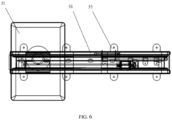
FIG. 6 is a main view of the mobile screen device in this embodiment; -
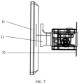
FIG. 7 is a side view of the mobile screen device in this embodiment. - The reference signs in the drawings are as follows:
1-screen assembly; 2-driving assembly; 3-sliding assembly; 4-shielding assembly; 11-screen; 12-second mounting bracket; 21-motor; 22-driving member; 31-sliding rail; 32-rotating member; 33-sliding member; 34-first mounting bracket; 35-mounting member; 41-roller shutter door; 311-first limiting slot; 312-second limiting slot. - The following will provide a clear and complete description of the technical solution in the embodiments of the present application in conjunction with the accompanying drawings. Obviously, the described embodiments are only part of the embodiments of the present application, not all of the embodiments. Based on the embodiments in the present application, all other embodiments obtained by those skilled in the art without creative work shall fall within the scope of protection of the present application.
- It should be noted that the terms "first", "second", etc. in the description and claims of the present application, as well as the accompanying drawings, are used to distinguish similar objects, without necessarily describing a specific order or sequence. It should be understood that the data used in this way can be interchanged in appropriate cases, such that the embodiments of the present application described here can be implemented in sequence other than those illustrated or described here. In addition, the terms "include" and "have", as well as any variations thereof, are intended to cover non-exclusive inclusion. For example, a process, method, system, product, or device that includes a series of steps or units, need not be limited to those clearly listed steps or units, but may also include other steps or units that are not clearly listed or inherent to these processes, methods, products, or devices.
- The existing technology has the following shortcomings: in addition to displaying vehicle driving information, the existing dashboard display screen can even display navigation, tire pressure monitoring and other information in some models. The combination of functions is rich and partially overlaps with the functions of the central control display screen, resulting in the redistribution and design of functions between the two. The increase in functionality also makes the central control display screen become wider, resulting in difficulty in layout. Furthermore, after installing and sliding the existing display screen according to the requirements, the gaps on both sides of the display screen cannot be blocked after moving left and right, and the internal structure of the display screen is visible on the appearance, which cannot meet the product appearance requirements
- In order to address the shortcomings of the existing technology, the present application is provided with a shielding assembly to shield the sliding assembly to avoid the internal structure of the sliding assembly from being seen from the outside, making the mobile screen device more aesthetically pleasing. Furthermore, the roller shutter door and the sliding member share the same sliding rail, making the overall size smaller. Moreover, the present application can clamp the roller shutter door by setting the first limiting slot and the second limiting slot, so as to prevent the roller shutter door from falling off and improve the safety performance of the mobile screen device.
- Referring to
FIGs. 1 to 7 , this embodiment provides a mobile screen device and a vehicle. The mobile screen device includes ascreen assembly 1, a drivingassembly 2, a slidingassembly 3, and a shieldingassembly 4 for shielding the slidingassembly 3. - The sliding
assembly 3 includes a slidingrail 31, a rotatingmember 32, and a slidingmember 33. The rotatingmember 32 is connected to the slidingmember 33. The slidingmember 33 is respectively connected to thescreen assembly 1 and the shieldingassembly 4. - The driving
assembly 2 is connected to the rotatingmember 32. The drivingassembly 2 is used to drive the rotatingmember 32 to rotate. - The shielding
assembly 4 is arranged in the slidingrail 31. The slidingmember 33 can drive the shieldingassembly 4 and thescreen assembly 1 to slide along the slidingrail 31 under the driving of the rotatingmember 32. - It should be noted that the present application is provided with the shielding
assembly 4 to shield the slidingassembly 3, thereby avoiding the internal structure of the slidingassembly 3 from being visible from the outside, making the mobile screen device more aesthetically pleasing, wherein the shieldingassembly 4 and thescreen assembly 1 move synchronously under the drive of the drivingassembly 2. - Preferably, the shielding
assembly 4 includes aroller shutter door 41 and a plurality of guide wheels. - The plurality of guide wheels are arranged on the same side of the
roller shutter door 41, and the guide wheels are arranged in the slidingrail 31. - Specifically, one end of the guide wheel is fixed on the
roller shutter door 41, and the other end of the guide wheel slides along the slidingrail 31. - In some possible embodiments, the shielding
assembly 4 only includes theroller shutter door 41, and does not include the guide wheels. Theroller shutter door 41 includes a first edge and a second edge which are oppositely arranged. The first edge is engaged in a first limitingslot 311, and the second edge is engaged in a second limitingslot 312. Theroller shutter door 41 can slide along the slidingrail 31 under the drive of the drivingassembly 2, such that theroller shutter door 41 can shield the interior of the slidingassembly 3, thus making the mobile screen device more aesthetically pleasing. - In other possible embodiments, the
roller shutter door 41 can be attached with appearance color texture to achieve decorative effect and make the mobile screen device more aesthetically pleasing. - Preferably, the
roller shutter door 41 is provided with a first mounting hole matching the slidingmember 33, and the slidingmember 33 is arranged in the first mounting hole. - In some possible embodiments, the number of the first mounting hole is one, and the size of the first mounting hole is larger than the size of the sliding
member 33. Two slidingmembers 33 are arranged in the first mounting hole, and one end of the slidingmember 33 passes through the first mounting hole and is connected to a second mounting bracket. - In other possible embodiments, the number of the first mounting hole is equal to the number of the sliding
member 33, and the shape of the first mounting hole is the same as the shape of the slidingmember 33, and the dimensions of the two are equal, such that the slidingmember 33 is fully embedded in the first mounting hole, thereby improving the connection stability of the two. - Preferably, the length of the
roller shutter door 41 is less than the perimeter of the slidingrail 31. - Specifically, the original length of the
roller shutter door 41 when unfolded is less than the perimeter of the slidingrail 31, such that theroller shutter door 41 can move along the slidingrail 31 with thescreen assembly 1, and meet the required moving distance of thescreen assembly 1. - Preferably, the sliding
rail 31 includes a first limitingslot 311 and a second limitingslot 312 which are oppositely arranged. - One edge of the
roller shutter door 41 provided with the guide wheels is arranged in the first limitingslot 311, and the other edge of theroller shutter door 41 is arranged in the second limitingslot 312, such that theroller shutter door 41 can slide along the slidingrail 31. - Specifically, one edge of the
roller shutter door 41 provided with the guide wheels is engaged in the first limitingslot 311, and the other edge of theroller shutter door 41 is engaged in the second limitingslot 312, so as to prevent theroller shutter door 41 from falling off from the slidingrail 31 and improve the connection stability of the overall structure. - In some possible embodiments, two opposite edges of the
roller shutter door 41 are each provided with the guide wheels, and the guide wheels at the two edges are respectively arranged in the first limitingslot 311 and the second limitingslot 312, such that theroller shutter door 41 can move more smoothly. - Preferably, the distance between the first limiting
slot 311 and the second limitingslot 312 is a first distance, the height of the shieldingassembly 4 is a second distance, and the first distance is not less than the second distance. - Specifically, the height of the
roller shutter door 41 is less than the first distance, and the sum of the height of theroller shutter door 41 and the height of the guide wheel is still less than the first distance. - Specifically, the depth of the second limiting
slot 311 is greater than the height of the guide wheel, making the clamping surface of theroller shutter door 41 and the slidingrail 31 larger, thereby improving the connection stability of the two. - Preferably, the sliding
assembly 3 further includes a mountingmember 35, one end of the mountingmember 35 is connected to the slidingrail 31, and the other end of the mountingmember 35 is used to connect to the surface to be installed. - Specifically, the number of the mounting
member 35 is multiple, and the specific number of the mountingmember 35 is set according to the actual requirements. - In this embodiment, the number of the mounting
member 35 is eight, and there are four mountingmembers 35 on both sides of the slidingrail 31, and the eight mountingmembers 35 are symmetrically arranged. - Preferably, a limiting structure is provided on the sliding
rail 31, and the limiting structure is used to limit the movement of the rotatingmember 32 along its axial direction. The limiting structure abuts against two ends of the rotatingmember 32, and the rotatingmember 32 can rotate relative to the limiting structure. - In some possible embodiments, the sliding
rail 31 includes two opposite limiting structures, and each of the limiting structures is provided with a third limiting slot. One end of the rotatingmember 31 is arranged in one of the third limiting slots, and the other end of the rotatingmember 31 is arranged in the other one of the third limiting slots. The two ends of the rotatingmember 31 are respectively in contact with the bottom of the two third limiting slots. - Preferably, the rotating
member 32 is arranged along the length direction of the slidingrail 31, and the length of the rotatingmember 32 is smaller than the length of the slidingrail 31. - In some possible embodiments, the length of the rotating
member 32 is required to be set according to the movement range of thescreen assembly 1. The length of the rotatingmember 32 can be set to be equal to the length of the slidingrail 31. - Preferably, the driving
assembly 2 includes amotor 21 and a drivingmember 22. Themotor 21 is fixed on the slidingrail 31. One end of the drivingmember 22 is connected to themotor 21, and the other end of the drivingmember 22 is connected to the rotatingmember 32, such that themotor 21 can drive the rotatingmember 32 to rotate. - Specifically, the
motor 21 includes an output shaft. The drivingmember 22 is respectively connected to the output shaft and the rotatingmember 32, such that themotor 21 transmits power to the rotatingmember 32 through the drivingmember 22, causing the rotatingmember 32 to rotate, driving the slidingmember 33 to move along the axial direction of the rotatingmember 32, thereby driving thescreen assembly 1 and the shieldingassembly 4 to move. - Preferably, the driving
member 22 is a conveyor belt, a conveyor chain, or a gear. - In some possible embodiments, when the driving
member 22 is a conveyor belt, the rotatingmember 32 is provided with a first pulley, the output shaft of themotor 21 is provided with a second pulley, the conveyor belt is sleeved on the first pulley and the second pulley, and the conveyor belt transmits the power of themotor 21 to the rotatingmember 32. - Preferably, the sliding
rail 31 is a C-shaped structure with openings at two ends. - The two ends of the sliding
rail 31 are each provided with a first mountingbracket 34 for limiting the position of the shieldingassembly 4, and the first mountingbracket 34 can abut against the shieldingassembly 4. - Specifically, the openings at the two ends of the sliding
rail 31 can facilitate the installation of the shieldingassembly 4, and the shieldingassembly 4 can be installed into the slidingrail 31 from the opening at one end of the slidingrail 31. - Preferably, the first mounting
bracket 34 is provided with a second mounting hole, and a connecting member is arranged in the second mounting hole. - The sliding
rail 31 is provided with a third mounting hole. The connecting member passes through the second mounting hole and the third mounting hole in sequence, such that the first mountingbracket 34 is detachably connected to the slidingrail 31. - Specifically, the shape of the first mounting
bracket 34 is adapted to the shape of the open end of the slidingrail 31. - Preferably, the number of the second mounting hole corresponds to the number of the third mounting hole, and the position of the second mounting hole corresponds to the position of the third mounting hole.
- In some possible embodiments, one of the first mounting
brackets 34 is fixedly connected to the slidingrail 31, and the other one of the first mountingbrackets 34 is detachably connected to the slidingrail 31. - Preferably, the rotating
member 32 is a lead screw, the slidingmember 33 is a nut, and the nut is threadedly connected to the lead screw. Thescreen assembly 1 is fixedly connected to the nut. - Preferably, the number of the sliding
member 33 is two, and the two slidingmembers 33 are each connected to the rotatingmember 32 and thescreen assembly 1. - In some possible embodiments, the number of the sliding
member 33 is one, one end of the slidingmember 33 is connected to the rotatingmember 32, and the other end of the slidingmember 33 is connected to thescreen assembly 1. - Preferably, the
screen assembly 1 includes ascreen 11 and asecond mounting bracket 12. One end of the second mountingbracket 12 is connected to thescreen 11, and the other end of the second mountingbracket 12 is connected to the slidingmember 33. - Specifically, the second mounting
bracket 12 is detachably connected to thescreen 11. - In some possible embodiments, the
screen 11 is provided with a first clamping portion, and the second mountingbracket 12 is provided with a second clamping portion. Thescreen 11 and the second mountingbracket 12 are clamped through the first clamping portion and the second clamping portion, making thescreen 11 and the second mountingbracket 12 detachably connected. - In other possible embodiments, the
screen 11 is provided with a first threaded hole, the second mountingbracket 12 is provided with a second threaded hole that matches the first threaded hole. A bolt is arranged inside the second threaded hole, and thescreen 11 and the second mountingbracket 12 are connected through the bolt. - The use process of the mobile screen device is as follows: when the
screen 11 needs to be moved, themotor 21 is controlled to rotate, thereby driving the rotatingmember 32 to rotate, and causing the slidingmember 33 to move along the axial direction of the rotatingmember 32. The slidingmember 33 drives theroller shutter door 41 and thescreen assembly 1 to move together along the axial direction of the rotatingmember 32. - The present application further provides a vehicle, which includes a dashboard and a mobile screen device as described above. The mobile screen device is arranged on the dashboard.
- Although the present application has been described through preferred embodiments, the present application is not limited to the embodiments described herein and further includes various changes and variations made without departing from the scope of the present application.
- In this description, the terms "front", "back", "up", "down", etc. are defined based on the positions of the elements in the drawings and between them, merely for the clarity and convenience of expressing the technical solution. It should be understood that the use of the directional words should not limit the scope of protection of the present application.
- In this description, the above embodiments and the features in the embodiments can be combined with each other If no conflict exists.
- The above disclosure is only a preferred embodiment of the present application, and of course, it cannot be used to limit the scope of the present application. Therefore, the equivalent changes made according to the claims of the present application still fall within the scope of the present application.
Claims (18)
- A mobile screen device, comprising a screen assembly (1), a driving assembly (2), a sliding assembly (3), and a shielding assembly (4) for shielding the sliding assembly (3);wherein the sliding assembly (3) comprises a sliding rail (31), a rotating member (32) and a sliding member (33); the rotating member (32) is connected to the sliding member (33), the sliding member (33) is respectively connected to the screen assembly (1) and the shielding assembly (4);the driving assembly (2) is connected to the rotating member (32), and the driving assembly (2) is configured to drive the rotating member (32) to rotate;the shielding assembly (4) is arranged in the sliding rail (31), and the sliding member (33) is driven by the rotating member (32) to move such that the sliding member (33) drives the shielding assembly (4) and the screen assembly (1) to slide along the sliding rail (31).
- The mobile screen device as claimed in claim 1, wherein the shielding assembly (4) comprises a roller shutter door (41) and a plurality of guide wheels;
the plurality of the guide wheels are arranged on the same side of the roller shutter door (41), and the guide wheels are arranged in the sliding rail (31). - The mobile screen device as claimed in claim 2, wherein the roller shutter door (41) is provided with a first mounting hole matching the sliding member (33), and the sliding member (33) is arranged in the first mounting hole.
- The mobile screen device as claimed in claim 2, wherein a length of the roller shutter door (41) is less than a perimeter of the sliding rail (31).
- The mobile screen device as claimed in claim 2, wherein the sliding rail (31) comprises a first limiting slot (311) and a second limiting slot (312) which are oppositely arranged;
one edge of the roller shutter door (41) with the guide wheels is arranged in the first limiting slot (311), and the other edge of the roller shutter door (41) is arranged in the second limiting slot (312), such that the roller shutter door (41) can slide along the sliding rail (31). - The mobile screen device as claimed in claim 5, wherein the distance between the first limiting slot (311) and the second limiting slot (312) is a first distance, the height of the shielding assembly (4) is a second distance, and the first distance is not less than the second distance.
- The mobile screen device as claimed in claim 1, wherein the sliding assembly (3) further comprises a mounting member (35), one end of the mounting member (35) is connected to the sliding rail (31), and the other end of the mounting member (35) is configured to connect to a surface to be installed.
- The mobile screen device as claimed in claim 1, wherein a limiting structure is provided on the sliding rail (31), the limiting structure is configured to limit the movement of the rotating member (32) along its axial direction, the limiting structure abuts against two ends of the rotating member (32), and the rotating member (32) can rotate relative to the limiting structure.
- The mobile screen device as claimed in claim 1, wherein the rotating member (32) is arranged along the length direction of the sliding rail (31), and the length of the rotating member (32) is less than the length of the sliding rail (31).
- The mobile screen device as claimed in claim 1, wherein the driving assembly (2) comprises a motor (21) and a driving member (22), the motor (21) is fixed on the sliding rail (31), one end of the driving member (22) is connected to the motor (21), and the other end of the driving member (22) is connected to the rotating member (32), such that the motor (21) can drive the rotating member (32) to rotate.
- The mobile screen device as claimed in claim 10, wherein the driving member (22) is a conveyor belt, a conveyor chain, or a gear.
- The mobile screen device as claimed in claim 1, wherein the sliding rail (31) is a C-shaped structure with openings at two ends;
the two ends of the sliding rail (31) are each provided with a first mounting bracket (34) for limiting the position of the shielding assembly (4), and the first mounting bracket (34) can abut against the shielding assembly (4). - The mobile screen device as claimed in claim 12, wherein the first mounting bracket (34) is provided with a second mounting hole, and a connecting member is arranged in the second mounting hole;
the sliding rail (31) is provided with a third mounting hole, and the connecting member passes through the second mounting hole and the third mounting hole in sequence, such that the first mounting bracket (34) is detachably connected to the sliding rail (31). - The mobile screen device as claimed in claim 13, wherein the number of the second mounting hole corresponds to the number of the third mounting hole, and the position of the second mounting hole corresponds to the position of the third mounting hole.
- The mobile screen device as claimed in claim 1, wherein the rotating member (32) is a lead screw, the sliding member (33) is a nut, the nut is threadedly connected to the lead screw, and the screen assembly (1) is fixedly connected to the nut.
- The mobile screen device as claimed in claim 15, wherein the number of the sliding member (33) is two, and the two sliding members (33) are each connected to the rotating member (32) and the screen assembly (1).
- The mobile screen device as claimed in claim 1, wherein the screen assembly (1) comprises a screen (11) and a second mounting bracket (12), one end of the second mounting bracket (12) is connected to the screen (11), and the other end of the second mounting bracket (12) is connected to the sliding member (33).
- A vehicle, comprising a dashboard and a mobile screen device as claimed in any one of claims 1 to 17, wherein the mobile screen device is arranged on the dashboard.
Applications Claiming Priority (1)
| Application Number | Priority Date | Filing Date | Title |
|---|---|---|---|
| PCT/CN2021/073343 WO2022155902A1 (en) | 2021-01-22 | 2021-01-22 | Mobile screen device and vehicle |
Publications (2)
| Publication Number | Publication Date |
|---|---|
| EP4282686A1 true EP4282686A1 (en) | 2023-11-29 |
| EP4282686A4 EP4282686A4 (en) | 2024-10-09 |
Family
ID=82549211
Family Applications (1)
| Application Number | Title | Priority Date | Filing Date |
|---|---|---|---|
| EP21920300.7A Withdrawn EP4282686A4 (en) | 2021-01-22 | 2021-01-22 | Mobile screen device and vehicle |
Country Status (3)
| Country | Link |
|---|---|
| EP (1) | EP4282686A4 (en) |
| CN (1) | CN116745199A (en) |
| WO (1) | WO2022155902A1 (en) |
Families Citing this family (2)
| Publication number | Priority date | Publication date | Assignee | Title |
|---|---|---|---|---|
| CN116587855B (en) * | 2023-04-03 | 2026-01-02 | 江苏联成开拓集团有限公司 | A car center console screen device with supplemental lighting |
| CN116901856B (en) * | 2023-07-14 | 2026-01-27 | 浙江吉利控股集团有限公司 | Mobile screen shielding mechanism and vehicle |
Family Cites Families (12)
| Publication number | Priority date | Publication date | Assignee | Title |
|---|---|---|---|---|
| DE102004005481A1 (en) * | 2004-02-04 | 2005-08-25 | Adam Opel Ag | Ventilation system for vehicle, comprising nozzle guided along roof supporting strut |
| DE102004044163B3 (en) * | 2004-09-13 | 2006-04-27 | Siemens Ag | Instrument panel for motor vehicle, has display for displaying information, where display is arranged before panel in view of passenger and movable along panel in horizontal direction by linear drive |
| DE102012019559A1 (en) * | 2012-10-05 | 2014-04-10 | GM Global Technology Operations LLC (n. d. Gesetzen des Staates Delaware) | Blend and/or sun guard arrangement for picture screen on dashboard of vehicle e.g. lorry, has protective device moving from rest state to functional state, and picture screen arranged in protective device that forms guard-obscure |
| CN203805797U (en) * | 2014-03-11 | 2014-09-03 | 广汽吉奥汽车有限公司 | Auxiliary dashboard sliding shutter mechanism |
| TWM509697U (en) * | 2015-06-18 | 2015-10-01 | Sun Yuan Technology Co Ltd | Retractable protection cover featuring smooth sliding |
| DE202015104594U1 (en) * | 2015-08-24 | 2015-09-18 | Ford Global Technologies, Llc | Motor vehicle vent |
| DE102017011102A1 (en) * | 2017-11-30 | 2018-06-07 | Daimler Ag | Rolling device for a display of a motor vehicle |
| CN209616896U (en) * | 2018-12-26 | 2019-11-12 | 江苏金邦利汽车部件有限公司 | A kind of automobile middle control plate |
| DE102019202005B3 (en) * | 2019-02-14 | 2020-06-18 | Volkswagen Aktiengesellschaft | Holder for a display and control unit for vehicles |
| CN111301169B (en) * | 2020-03-31 | 2022-08-02 | 北京新能源汽车股份有限公司 | Instrument board assembly for vehicle and vehicle |
| CN111731099A (en) * | 2020-06-15 | 2020-10-02 | 北京汽车股份有限公司 | Display screen mobile device and vehicle |
| CN111845348A (en) * | 2020-06-16 | 2020-10-30 | 宁波吉利汽车研究开发有限公司 | A vehicle auxiliary instrument device and vehicle |
-
2021
- 2021-01-22 EP EP21920300.7A patent/EP4282686A4/en not_active Withdrawn
- 2021-01-22 WO PCT/CN2021/073343 patent/WO2022155902A1/en not_active Ceased
- 2021-01-22 CN CN202180091184.5A patent/CN116745199A/en active Pending
Also Published As
| Publication number | Publication date |
|---|---|
| WO2022155902A1 (en) | 2022-07-28 |
| CN116745199A (en) | 2023-09-12 |
| EP4282686A4 (en) | 2024-10-09 |
Similar Documents
| Publication | Publication Date | Title |
|---|---|---|
| US9857587B2 (en) | Head-up display device | |
| CN104006517B (en) | Air outlet assembly and air conditioner with same | |
| WO2022155902A1 (en) | Mobile screen device and vehicle | |
| CN104260675A (en) | Rotatable automobile display screen assembly | |
| CN113513665A (en) | Combined vehicle-mounted display screen and mounting method thereof | |
| CN202156368U (en) | Vehicle-mounted electric turnover display screen | |
| CN113335192B (en) | Sliding screen mounting structure and vehicle comprising same | |
| CN202071732U (en) | Multifunctional vehicle-mounted mobile device | |
| CN203283140U (en) | Windshield simple fixed vehicle camera device | |
| WO2005018968A3 (en) | Mobile audio/visual presentation system and method | |
| CN216578257U (en) | FRP plane skylight production is with device of borduring | |
| CN221175675U (en) | Concealed vehicle-mounted display screen | |
| CN208085618U (en) | Display screen assembly for vehicle and vehicle with same | |
| CN203697923U (en) | Rear drainage tank of auto sunroof | |
| CN207029048U (en) | Mounting bracket, Vehicular instrument panel and vehicle | |
| CN201022487Y (en) | Built in type computer office desk | |
| KR20230120318A (en) | Display module for vehicle | |
| CN221377006U (en) | Adjustment mechanism and detection system of vehicle-mounted display screen | |
| CN222432221U (en) | Vehicle-mounted display screen and automobile | |
| CN116901856B (en) | Mobile screen shielding mechanism and vehicle | |
| CN107386148B (en) | A kind of traffic sign device | |
| CN221605976U (en) | Electric bicycle instrument panel with anti-glare function | |
| CN218074323U (en) | Unmanned aerial vehicle show stand and unmanned aerial vehicle education device | |
| CN2907186Y (en) | Space-saving and easy-to-assemble slide panel side wheel device | |
| CN220399791U (en) | Vehicle-mounted projection screen |
Legal Events
| Date | Code | Title | Description |
|---|---|---|---|
| STAA | Information on the status of an ep patent application or granted ep patent |
Free format text: STATUS: THE INTERNATIONAL PUBLICATION HAS BEEN MADE |
|
| PUAI | Public reference made under article 153(3) epc to a published international application that has entered the european phase |
Free format text: ORIGINAL CODE: 0009012 |
|
| STAA | Information on the status of an ep patent application or granted ep patent |
Free format text: STATUS: REQUEST FOR EXAMINATION WAS MADE |
|
| 17P | Request for examination filed |
Effective date: 20230718 |
|
| AK | Designated contracting states |
Kind code of ref document: A1 Designated state(s): AL AT BE BG CH CY CZ DE DK EE ES FI FR GB GR HR HU IE IS IT LI LT LU LV MC MK MT NL NO PL PT RO RS SE SI SK SM TR |
|
| DAV | Request for validation of the european patent (deleted) | ||
| DAX | Request for extension of the european patent (deleted) | ||
| REG | Reference to a national code |
Ref country code: DE Ref legal event code: R079 Free format text: PREVIOUS MAIN CLASS: B60K0037020000 Ipc: B60K0037000000 |
|
| A4 | Supplementary search report drawn up and despatched |
Effective date: 20240911 |
|
| RIC1 | Information provided on ipc code assigned before grant |
Ipc: B60R 11/02 20060101ALI20240905BHEP Ipc: B62D 25/14 20060101ALI20240905BHEP Ipc: B60K 37/00 20060101AFI20240905BHEP |
|
| STAA | Information on the status of an ep patent application or granted ep patent |
Free format text: STATUS: THE APPLICATION IS DEEMED TO BE WITHDRAWN |
|
| 18D | Application deemed to be withdrawn |
Effective date: 20250402 |