EP4282537B1 - Gesicherte einheit zur abgabe eines produkts mittels eines in einer kartusche gespeicherten hochdruckgases - Google Patents
Gesicherte einheit zur abgabe eines produkts mittels eines in einer kartusche gespeicherten hochdruckgases Download PDFInfo
- Publication number
- EP4282537B1 EP4282537B1 EP23173802.2A EP23173802A EP4282537B1 EP 4282537 B1 EP4282537 B1 EP 4282537B1 EP 23173802 A EP23173802 A EP 23173802A EP 4282537 B1 EP4282537 B1 EP 4282537B1
- Authority
- EP
- European Patent Office
- Prior art keywords
- pressure
- cap
- valve
- reducing unit
- relative
- Prior art date
- Legal status (The legal status is an assumption and is not a legal conclusion. Google has not performed a legal analysis and makes no representation as to the accuracy of the status listed.)
- Active
Links
Images




Classifications
-
- B—PERFORMING OPERATIONS; TRANSPORTING
- B65—CONVEYING; PACKING; STORING; HANDLING THIN OR FILAMENTARY MATERIAL
- B65D—CONTAINERS FOR STORAGE OR TRANSPORT OF ARTICLES OR MATERIALS, e.g. BAGS, BARRELS, BOTTLES, BOXES, CANS, CARTONS, CRATES, DRUMS, JARS, TANKS, HOPPERS, FORWARDING CONTAINERS; ACCESSORIES, CLOSURES, OR FITTINGS THEREFOR; PACKAGING ELEMENTS; PACKAGES
- B65D83/00—Containers or packages with special means for dispensing contents
- B65D83/14—Containers for dispensing liquid or semi-liquid contents by internal gaseous pressure, i.e. aerosol containers comprising propellant
- B65D83/60—Containers for dispensing liquid or semi-liquid contents by internal gaseous pressure, i.e. aerosol containers comprising propellant with contents and propellant separated
- B65D83/673—Containers for dispensing liquid or semi-liquid contents by internal gaseous pressure, i.e. aerosol containers comprising propellant with contents and propellant separated at least a portion of the propellant being separated from the product and incrementally released by means of a pressure regulator
-
- B—PERFORMING OPERATIONS; TRANSPORTING
- B05—SPRAYING OR ATOMISING IN GENERAL; APPLYING FLUENT MATERIALS TO SURFACES, IN GENERAL
- B05B—SPRAYING APPARATUS; ATOMISING APPARATUS; NOZZLES
- B05B7/00—Spraying apparatus for discharge of liquids or other fluent materials from two or more sources, e.g. of liquid and air, of powder and gas
- B05B7/24—Spraying apparatus for discharge of liquids or other fluent materials from two or more sources, e.g. of liquid and air, of powder and gas with means, e.g. a container, for supplying liquid or other fluent material to a discharge device
- B05B7/2402—Apparatus to be carried on or by a person, e.g. by hand; Apparatus comprising containers fixed to the discharge device
- B05B7/2405—Apparatus to be carried on or by a person, e.g. by hand; Apparatus comprising containers fixed to the discharge device using an atomising fluid as carrying fluid for feeding, e.g. by suction or pressure, a carried liquid from the container to the nozzle
- B05B7/2416—Apparatus to be carried on or by a person, e.g. by hand; Apparatus comprising containers fixed to the discharge device using an atomising fluid as carrying fluid for feeding, e.g. by suction or pressure, a carried liquid from the container to the nozzle characterised by the means for producing or supplying the atomising fluid, e.g. air hoses, air pumps, gas containers, compressors, fans, ventilators, their drives
- B05B7/2421—Gas containers
Definitions
- the present invention relates to the use of a high pressure gas contained in a cartridge or refill.
- the invention relates in particular to the use of high pressure gas after expansion to provide a low pressure gas capable of being used in a sealed utilization chamber in which a receiving sub-assembly is arranged, in particular a sub-assembly capable of using the low pressure gas as propellant gas.
- the invention finds application, for example, in the field of dispensing liquid or pasty products, particularly in the form of aerosols, by offering a solution allowing a user to replace the high-pressure gas cartridge and/or the refill of the subassembly with product to be dispensed under conditions guaranteeing the safety of the user with regard to the pressure levels prevailing in the different zones of the assembly during the various handling operations envisaged.
- the document DE102020129857 illustrates an example of the design of an assembly, suitable for the distribution of a product by means of a pressurized gas.
- the set 20 represented in the Figure 1 is generally cylindrical in shape with vertical axis A.
- the assembly 20 comprises, vertically from top to bottom, an upper cover 22, an intermediate pressure reduction block 24 and a lower housing 26.
- the upper cover 22 is fixed in a removable manner on the pressure reducing block 24, here on the upper part 36 of the body 33 of the pressure reducing block 24, by mounting by means of a bayonet type mechanism so as to access the interior of the upper part of the assembly 20 which here houses a sub-assembly for dispensing a product which is contained in a reservoir or a refill which it is necessary to be able to replace when its contents are exhausted.
- the bayonet type mechanism is a mounting and locking mechanism which comprises a series of lugs which cooperate with complementary “L” shaped grooves which allow the combination of successive movements of engagement by axial translation then locking by rotation.
- buttons 28 for controlling the distribution of the product.
- buttons 28 and 29 By pressing button 28, the user causes the product to come out, for example in spray form, through a valve whose opening is controlled by the button.
- the propellant of the product is a low-pressure gas - called low-pressure gas - which is permanently contained inside a sealed internal chamber 30 (See Figure 2 ) of the upper cover 22 called the user chamber.
- the internal chamber 30 is supplied with low pressure gas by an outlet 53 of the pressure reduction block 24.
- the pressure reducing block 24 comprises an inlet 25 for high pressure gas - called high pressure gas - which is contained in a high pressure gas cartridge 32 whose outlet orifice 34 is connected to this inlet orifice 25 (See Figure 3A ).
- the pressure reducing block 24 has the function of reducing the value of the pressure of the high pressure gas prevailing in the cartridge 32 to supply the utilization chamber 30 with low pressure gas.
- the cartridge contains a gas at a pressure of approximately 60 bars which is expanded by the pressure reduction block 24 to a usage value of between 3 and 4 bars to supply the usage chamber 30.
- the cartridge 32 is removably connected to the pressure reducing block 24 to allow the replacement of an empty cartridge with a new full cartridge.
- the lower housing 26 is removably fixed to the pressure reducing block 24, here by screwing, onto the lower part 38 of the body 33 of the pressure reducing block 24.
- the body 33 of the pressure reduction block 24 is a cylindrical body whose lower part 38 is threaded and whose upper part 36 - for the assembly and fixing of the upper cover 22 - here comprises a set of three “L” shaped grooves 40 belonging to the bayonet fixing mechanism, each of which comprises an axial inlet section 42 which opens axially upwards into the horizontal upper face 37 of the upper part 36.
- Each axial section 42 is extended by a circumferential section 44 which here extends in a horizontal plane.
- the bayonet fixing mechanism advantageously allows it to absorb the forces induced by pressure.
- the body 33 of the pressure reduction block 24 comprises three peripheral axial bores 46, 52 and 62 - with parallel axes A46, A54 and A64 - each of which opens into the upper face 37 and which are here distributed angularly in a regular manner.
- a first bore 46 houses a ball plunger 48 belonging to a safety locking mechanism of the upper cover 22 on the pressure reduction block 24.
- a second bore 52 houses a valve 54, called a supply valve, which is a normally closed type valve for closing the bore 52.
- valve reference 37890-06 marketed by the applicant.
- the supply valve 54 comprises a rod 56 for controlling its opening, the free end 58 of which projects axially beyond the upper face 37 and extends inside the internal chamber 30 of the upper cover 22.
- the opening is caused by axially urging the supply control rod 56, here axially from top to bottom, towards the inside of the bore 52 to move the valve flap from its seat.
- the bottom 60 of the bore 52 is supplied with low pressure gas by the pressure reduction block 24 and, when the valve 54 is open, the gas enters the internal chamber 30 through the upper emerging end 53 of the bore 52 which constitutes the low pressure gas outlet 53 of the pressure reduction block 24.
- a channel - not visible in these figures - which can be made using a hole connects the outlet of the pressure reducing block to the chamber 30.
- a third bore 62 constitutes a purge conduit for the internal chamber 30.
- a valve 64 called a purge valve, is housed in the bore 62.
- the purge valve 64 is a normally closed type valve which closes the conduit to isolate the internal chamber 30.
- the purge valve 64 comprises a rod 66 for controlling its opening, the free end 68 of which projects axially beyond the upper face 37 and extends inside the internal chamber 30 of the upper cover 22.
- the opening is caused by axially urging the supply control rod 66, here axially from top to bottom, towards the inside of the bore 62 to move the valve flap from its seat.
- the upper emerging end 63 of the bore 62 constitutes the upstream end of the purge conduit while its lower end 70 constitutes its downstream end considering the direction of circulation of the gas when the purge valve 64 is open.
- the axes A54 and A64 of the supply valves 54 and purge valves 64 are here parallel to the main vertical axis of the body 33.
- the internal chamber 30 is thus permanently connected to the low pressure gas outlet and the upstream end 63 of the purge conduit 62 of the pressure reduction block 24.
- the lower end tubular section 80 of the upper cover 22 is the section for mounting and fixing the upper cover 22 on the upper part 36 of the pressure reduction block 24 which for this purpose comprises a set of three fixing lugs 84 complementary to the “L” shaped grooves 40 belonging to the bayonet fixing mechanism.
- the three lugs 84 are arranged in a horizontal plane which is close to the lower end axial edge 82 of the upper cap 22.
- An O-ring 86 provides a seal between the inner concave side wall 79 of the lower end tubular section 80 of the upper cap 22 and the outer convex side wall 35 of the upper part 36 of the body 33 of the pressure reducing block 24.
- the lower end tubular section 80 of the upper cover 22 comprises a cam 88 for sequenced control of the opening and/or closing of the supply valves 54 and purge valves 64, and of locking.
- the lower end tubular section 80 comprises a cam produced in the form of an internal radial shoulder 88 which, without limitation, is here divided into two sections 90 and 92.
- the first cam profile 94 belongs to the safety locking mechanism of the upper cover 22 on the pressure reducing block 24 and it cooperates with the ball 49 of the ball pusher 48.
- a ramp profile which ends with a locking notch 98, in the form of a spherical cap, which is capable of partially housing the ball 49 when the latter is angularly aligned with the locking notch 98.
- the second cam profile 96 constitutes the control cam profile with which the free end 58 of the supply control rod 56 and the free end 68 of the purge control rod 66 cooperate simultaneously.
- the vertical position of the cam profile 96 relative to the plane of the lugs 84 is such that, when the lugs are axially opposite the circumferential sections 44 of the grooves 40, the free ends 58 and 68 are in contact with the cam profile 96 against which they bear under the action of the return springs of the corresponding valves 54 and 64.
- a three-lug design 84 regularly spaced at one hundred and twenty degrees of angle allows in principle three mounting positions.
- the keying means are here produced by sizing one of the three lugs 84 smaller than the other two and a corresponding complementary vertical section 42 narrower than the other two.
- the assembly of the upper cover 22 on the pressure reduction block 24 is carried out by axially introducing the lugs 84 into the axial sections.
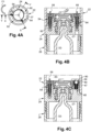
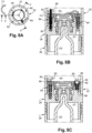
- This relative angular position is the first extreme angular position - called assembly (or disassembly) - of the upper cover 22 relative to the pressure reduction block 24.
- the user can rotate the upper cover 22 relative to the pressure reduction block 24 according to a maximum stroke corresponding to the extension of the circumferential sections 44 of the “L” grooves 40.
- This “locked” position corresponds to the second extreme angular position, called fixing, of the upper cover 22 on the pressure reduction block 24.
- this relative rotation stroke of the upper cover 22 with respect to the pressure reduction block 24 is carried out in the clockwise direction according to the arrows F1.
- This angular stroke begins with unlocking which requires the user to initially apply a higher disassembly torque to remove the ball 49 from its locking notch 98.
- a high pressure gas cartridge 32 is attached to the pressure reducing block 24 and its outlet orifice 34 is connected to the inlet 25.
- the lower chamber 27 of the lower housing 26 is connected to ambient pressure, generally to atmospheric pressure.
- the pressure reducing block 24 performs its function as a pressure regulator and it supplies the bottom 60 of the bore 52 with low pressure gas.
- the upper cover 22 is put in place in its first extreme angular position, the lugs 84 being aligned with the circumferential sections 44.
- the user can perceive tactilely and/or audibly that the second extreme position of fixing of the upper cover 22 has been reached due to the “arrival” of the locking ball 49 in the locking notch 98.
- the assembly 30 is thus in its state of use and this state is also secure without risk of accidental involuntary disassembly of the upper cover 22 due to the action of the locking mechanism 48-98.
- the supply valve 54 is thus closed again before the upcoming opening of the purge valve 64, thus avoiding any emptying or purging of the internal chamber 30 while it would still be supplied with low pressure gas.
- the cam profile 96 caused the opening of the purge valve 64 and therefore - during this angular travel - the progressive emptying (according to the arrow F4) of the internal chamber 30 whose internal pressure returns to ambient pressure, generally atmospheric, before the upper cover 22 can be removed.
- the design of the purge valve 64 is such that it constitutes a safety valve in the event of overpressure in the internal chamber 30 of use, that is to say for example in a hypothesis in which the pressure reduction block 24 would be faulty and would cause the internal chamber to be supplied with gas at high pressure, or even with gas at the high pressure of the cartridge 32.
- the purge valve 64 opens automatically and the internal chamber 30 empties and the pressure prevailing there is brought back to ambient pressure.
- a locking mechanism in one of the circumferential sections 44 in the form of at least one ball pusher with which an associated lug cooperates.
- Block 24 The structural and functional design of Block 24 is unchanged.
- the axes A54 and A64 of the supply 54 and purge 64 valves are inclined relative to the main vertical axis of the body 33.
- the locking mechanism of the upper cap 22 is of a different design.
- the body 33 of the block 24 is provided in its convex side wall with a locking button 48 which is mounted to slide vertically in a complementary groove 100 which opens axially upwards into the axial annular face 102 of the central part of the body 33.
- the upper part of the locking button 48 is shaped into a locking hook 49 in the form of an inclined face which provides the same function as the locking ball mentioned above.
- the locking button 48 is elastically returned upwards into its active upper locking position by an elastic blade 47 (See Figure 11 ) which performs the same function as the return spring 47 mentioned previously.
- the active upper hook-forming locking portion 49 extends above the plane of the annular face 102.
- the locking button 48 is designed to cooperate with a complementary locking notch 98 which is formed in the lower end axial edge 82 of the upper cap 22 and which allows the locking of the upper cap 22 on the body 33 of the block 24 in its second extreme angular position.
- the lower end axial edge 82 of the upper cap 22 comprises another intermediate complementary notch 99 which is associated with the intermediate angular position of the upper cap 22 relative to the body 24.
- this other notch 99 allows the user to carry out the angular disassembly stroke necessarily in two stages.
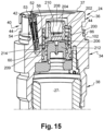
- An internal horizontal partition 204 divides the interior of the upper stage of the piston 200 into two lower chambers 206 and 208, each of which communicates with the peripheral chamber 209 in which the calibration spring 202 is housed and which communicates with the bottom 60 of the bore 52 by a channel 214.
- a seal 210 in the form of a pellet made of elastomeric material is housed under the internal partition 204 and is capable of cooperating with the upper face of a fixed connection 212 which receives the upper end of the high-pressure gas cartridge.
- the calibration value of the spring 202 combined with the various frictions and the action of the low pressure (for example equal to 3.5 or 4 bars) prevailing in the chamber 209 ensures a balance of the piston 200 which is stressed by the high pressure prevailing in the high pressure gas cartridge (for example equal to 60 bars).
Landscapes
- Chemical & Material Sciences (AREA)
- Dispersion Chemistry (AREA)
- Engineering & Computer Science (AREA)
- Mechanical Engineering (AREA)
- Filling Or Discharging Of Gas Storage Vessels (AREA)
Claims (9)
- Baugruppe (20), die zum Abgeben eines Produkts mittels eines unter Druck stehenden Gases geeignet ist, mit:- a) einer Hochdruckgaskartusche (32);- b) einem Druckreduzierblock (24) mit:-- einem Hochdruckgaseinlass (25), mit dem die Hochdruckgaskartusche (32) lösbar verbunden ist;-- einem Niedrigdruckgasauslass (53), in dem ein Versorgungsventil (54) angeordnet ist, das normalerweise geschlossen ist und eine Versorgungssteuerungsstange (56) aufweist, die das Öffnen des Versorgungsventils (54) steuert;-- einer Abführleitung (62), in der ein Abführventil (64) angeordnet ist, das normalerweise geschlossen ist und eine Abführsteuerungsstange (66) aufweist, die das Öffnen des Abführventils (64) steuert, um die Zirkulation von Gas von einem stromaufwärtigen Ende (63) zu einem stromabwärtigen Ende (70) der Abführleitung (62) zu ermöglichen;- c) und einer Kappe (22):dadurch gekennzeichnet, dass die Kappe einen Nocken (96) aufweist, der mit der Versorgungssteuerungsstange (56) und/oder mit der Abführsteuerungsstange (66) zusammenwirkt, um sequenziell das Öffnen und/oder Schließen des Versorgungsventils (54) und/oder des Abführventils (64) in Abhängigkeit von der Winkelposition der Kappe (22) relativ zu dem Druckreduzierblock (24) zwischen ihrer ersten extremen Winkelposition und ihrer zweiten extremen Winkelposition zu bewirken.-- die demontierbar am Druckreduzierblock (24) befestigt ist und mit diesem eine innere Nutzkammer (30) abgrenzt, die durch den Auslass (53) des Druckreduzierblocks (24) mit Niedrigdruckgas versorgt wird und die mit dem stromaufwärtigen Ende (63) der Abführleitung (62) verbunden ist;-- die relativ zu dem Druckreduzierblock (24) drehbar beweglich ist zwischen:i) einer ersten extremen Winkelposition zum Montieren oder Demontieren der Kappe (22) an dem Druckreduzierblock (24);ii) und einer zweiten extremen Winkelposition zum Befestigen der Kappe (22) an dem Druckreduzierblock (24),
- Baugruppe (20) nach Anspruch 1, dadurch gekennzeichnet, dass:- in der ersten extremen Winkelposition der Kappe (22) relativ zum Druckreduzierblock (24) unter der Wirkung des Nockens (96) das Versorgungsventil (54) geschlossen ist und das Abführventil (64) geöffnet ist;- während seiner Drehung relativ zum Druckreduzierblock (24) von seiner ersten extremen Winkelposition zu seiner zweiten extremen Winkelposition der Nocken (96) nacheinander das Schließen des Abführventils (64) und dann das Öffnen des Versorgungsventils (54) bewirkt;- in der zweiten extremen Winkelposition der Kappe (22) relativ zum Druckreduzierblock (24) unter der Wirkung des Nockens (96) das Versorgungsventil (54) geöffnet ist und das Abführventil (64) geschlossen ist.
- Baugruppe (20) nach Anspruch 1, dadurch gekennzeichnet, dass:- in der zweiten extremen Winkelposition der Kappe (22) relativ zum Druckreduzierblock (24) unter der Wirkung des Nockens (96) das Versorgungsventil (54) geöffnet ist und das Abführventil (64) geschlossen ist;- während seiner Drehung relativ zum Druckreduzierblock (24) von seiner ersten extremen Winkelposition zu seiner zweiten extremen Winkelposition der Nocken (96) nacheinander das Schließen des Versorgungsventils (54) und dann das Öffnen des Abführventils (64) bewirkt;- in der ersten extremen Winkelposition der Kappe (22) relativ zum Druckreduzierblock (24) unter der Wirkung des Nockens (96) das Versorgungsventil (54) geschlossen ist und das Abführventil (64) geöffnet ist.
- Baugruppe (20) nach einem der vorstehenden Ansprüche,
dadurch gekennzeichnet, dass sie Mittel (48, 98) zum Verriegeln der Kappe (22) auf dem Druckreduzierblock (24) in ihrer zweiten extremen Winkelposition aufweist. - Baugruppe (20) nach Anspruch 4, dadurch gekennzeichnet, dass sie ein Element (48) zum manuellen Steuern der Entriegelung der Verriegelungsmittel aufweist.
- Baugruppe (20) nach einem der vorstehenden Ansprüche,
dadurch gekennzeichnet, dass sie einen Bajonettmechanismus zum demontierbaren Befestigen der Kappe (22) auf dem Druckreduzierblock (24) aufweist, einen Bajonettbefestigungsmechanismus, bei dem mindestens eine Befestigungsnase (84) geeignet ist, sich in einer komplementären Nut (40, 42, 44) entlang eines Winkelwegs zu bewegen, der dem Winkelweg der Drehung der Kappe (22) relativ zu dem Druckreduzierblock (24) zwischen ihrer ersten extremen Winkelposition und ihrer zweiten extremen Winkelposition entspricht. - Baugruppe (20) nach Anspruch 6, dadurch gekennzeichnet, dass in der ersten extremen Winkelposition der Kappe (22) relativ zu dem Druckreduzierblock (24) der Translationsweg der Kappe (22) relativ zu dem Druckreduzierblock (24) entlang ihrer Rotationsachse relativ zu dem Druckreduzierblock (24), um die mindestens eine Nase (84) gegenüber dem Eingang (42) der komplementären Nut (40, 42, 44) zu positionieren, das Öffnen des normalerweise geschlossenen Abführventils (64) bewirkt.
- Baugruppe (20) nach einem der vorstehenden Ansprüche,
dadurch gekennzeichnet, dass in der zweiten extremen Winkelposition der Kappe (22) relativ zu dem Druckreduzierblock (24), in der das Abführventil (64) geschlossen ist, das Abführventil (64) die Funktion eines Sicherheitsventils gewährleistet, das sich automatisch öffnet, wenn der Druck an dem stromaufwärtigen Ende (63) der Abführleitung (62) größer ist als ein bestimmter Schwellenwert. - Baugruppe (20) nach einem der vorstehenden Ansprüche,
dadurch gekennzeichnet, dass das freie Ende (58) der Versorgungsstange (56) und das freie Ende (68) der Abführsteuerungsstange (66) in die geschlossene (30) der Kappe (22) hineinragen, und dass der Nocken (96) ein innerer radialer Absatz der Kappe (22) ist, dessen axiale Ringfläche (102) ein Nockenprofil aufweist, das geeignet ist, mit den freien Enden (58, 68) der Versorgungssteuerungs- und Abführsteuerungsstangen (56, 66) zusammenzuwirken.
Applications Claiming Priority (1)
| Application Number | Priority Date | Filing Date | Title |
|---|---|---|---|
| FR2205030A FR3135973B1 (fr) | 2022-05-25 | 2022-05-25 | Ensemble sécurisé pour la distribution d’un produit au moyen d’un gaz haute pression stocké dans une cartouche |
Publications (3)
| Publication Number | Publication Date |
|---|---|
| EP4282537A1 EP4282537A1 (de) | 2023-11-29 |
| EP4282537C0 EP4282537C0 (de) | 2025-05-07 |
| EP4282537B1 true EP4282537B1 (de) | 2025-05-07 |
Family
ID=82594794
Family Applications (1)
| Application Number | Title | Priority Date | Filing Date |
|---|---|---|---|
| EP23173802.2A Active EP4282537B1 (de) | 2022-05-25 | 2023-05-17 | Gesicherte einheit zur abgabe eines produkts mittels eines in einer kartusche gespeicherten hochdruckgases |
Country Status (2)
| Country | Link |
|---|---|
| EP (1) | EP4282537B1 (de) |
| FR (1) | FR3135973B1 (de) |
Family Cites Families (3)
| Publication number | Priority date | Publication date | Assignee | Title |
|---|---|---|---|---|
| NL1009292C1 (nl) * | 1998-05-29 | 1999-11-30 | Packaging Tech Holding Sa | Drukcontrole-inrichting voor het behouden van een constante vooraf bepaalde druk in een container. |
| AUPS023702A0 (en) * | 2002-01-31 | 2002-02-21 | Fraser-Easton, Gilbert | Pressure regulating device for a pressurised dispensing vessel |
| DE102020129857A1 (de) * | 2020-11-12 | 2022-05-12 | Beiersdorf Aktiengesellschaft | Wiederbefüllbarerer Fluidspender |
-
2022
- 2022-05-25 FR FR2205030A patent/FR3135973B1/fr not_active Expired - Fee Related
-
2023
- 2023-05-17 EP EP23173802.2A patent/EP4282537B1/de active Active
Also Published As
| Publication number | Publication date |
|---|---|
| EP4282537C0 (de) | 2025-05-07 |
| FR3135973A1 (fr) | 2023-12-01 |
| FR3135973B1 (fr) | 2024-05-10 |
| EP4282537A1 (de) | 2023-11-29 |
Similar Documents
| Publication | Publication Date | Title |
|---|---|---|
| EP1935503B1 (de) | Kompaktpumpe mit Gelenkkupplungsbewegung der Düse in Bezug auf das Ventil | |
| EP2926914B1 (de) | Verfahren zur flüssigkeitsextraktion aus einem flüssigkeitsverteilungsgerät mithilfe von gaseinspritzung | |
| EP0581947B1 (de) | Behälter zum spenden von flüssigkeiten | |
| EP2004521B1 (de) | Vorrichtung zur abgabe eines flüssigen produkts | |
| WO1986004163A1 (fr) | Reducteur-regulateur de pression pour la distribution d'un produit gazeux, liquide, visqueux, pulverulent ou pateux | |
| FR2698341A1 (fr) | Dispositif aérosol rechargeable en gaz comprimé. | |
| FR2641337A2 (fr) | Pompe a precompression pour la diffusion d'un liquide | |
| EP0930244A1 (de) | Einheit zur Aufbewahrung und Ausgabe unter Druck stehender Produkte, wobei das Unterdrucksetzen extemporiert erfolgt | |
| FR2994111A1 (fr) | Dispositif de nettoyage pour pistolet de pulverisation | |
| EP0960829A1 (de) | Ventil sowie Aufbewahrungs- und Ausgabevorrichtung mit einem solchen Ventil | |
| EP1628883B1 (de) | Fluidproduktspender | |
| EP4282537A1 (de) | Gesicherte einheit zur abgabe eines produkts mittels eines in einer kartusche gespeicherten hochdruckgases | |
| EP1651539B1 (de) | Fluidproduktabgabekopf | |
| WO2017137684A1 (fr) | Distributeur de produit fluide | |
| WO2006003297A1 (fr) | Pompe simplifiée pour distributeur de produits liquides sans reprise d'air | |
| FR2823845A1 (fr) | Dispositif pour le dosage de produits liquides ou en gel | |
| WO2022069843A1 (fr) | Valve doseuse | |
| FR3079725A1 (fr) | Dispositif de fermeture pour récipient préssurisé contenant un produit, notamment un produit cosmétique | |
| EP2707148B1 (de) | Pumpe zum dosieren und zur abgabe eines flüssigen oder viskosen produktes | |
| EP4257868A1 (de) | Ventil für einen gasbehälter mit verbessertem integriertem expander | |
| EP3464990A1 (de) | Gegen das befüllen gesicherter nicht wiederbefüllbarer gaszylinder | |
| FR2563312A1 (fr) | Soupape de reduction de pression | |
| EP4221900A1 (de) | Abgabevorrichtung mit einem festpunktrückschlagventil | |
| EP1230031B1 (de) | Pumpe mit schneller hin- und herbewegung | |
| WO2003086650A1 (fr) | Pompe de distribution de produit fluide |
Legal Events
| Date | Code | Title | Description |
|---|---|---|---|
| PUAI | Public reference made under article 153(3) epc to a published international application that has entered the european phase |
Free format text: ORIGINAL CODE: 0009012 |
|
| STAA | Information on the status of an ep patent application or granted ep patent |
Free format text: STATUS: THE APPLICATION HAS BEEN PUBLISHED |
|
| AK | Designated contracting states |
Kind code of ref document: A1 Designated state(s): AL AT BE BG CH CY CZ DE DK EE ES FI FR GB GR HR HU IE IS IT LI LT LU LV MC ME MK MT NL NO PL PT RO RS SE SI SK SM TR |
|
| STAA | Information on the status of an ep patent application or granted ep patent |
Free format text: STATUS: REQUEST FOR EXAMINATION WAS MADE |
|
| 17P | Request for examination filed |
Effective date: 20240320 |
|
| RBV | Designated contracting states (corrected) |
Designated state(s): AL AT BE BG CH CY CZ DE DK EE ES FI FR GB GR HR HU IE IS IT LI LT LU LV MC ME MK MT NL NO PL PT RO RS SE SI SK SM TR |
|
| GRAP | Despatch of communication of intention to grant a patent |
Free format text: ORIGINAL CODE: EPIDOSNIGR1 |
|
| STAA | Information on the status of an ep patent application or granted ep patent |
Free format text: STATUS: GRANT OF PATENT IS INTENDED |
|
| INTG | Intention to grant announced |
Effective date: 20240718 |
|
| GRAJ | Information related to disapproval of communication of intention to grant by the applicant or resumption of examination proceedings by the epo deleted |
Free format text: ORIGINAL CODE: EPIDOSDIGR1 |
|
| STAA | Information on the status of an ep patent application or granted ep patent |
Free format text: STATUS: REQUEST FOR EXAMINATION WAS MADE |
|
| GRAP | Despatch of communication of intention to grant a patent |
Free format text: ORIGINAL CODE: EPIDOSNIGR1 |
|
| STAA | Information on the status of an ep patent application or granted ep patent |
Free format text: STATUS: GRANT OF PATENT IS INTENDED |
|
| INTC | Intention to grant announced (deleted) | ||
| INTG | Intention to grant announced |
Effective date: 20241204 |
|
| GRAS | Grant fee paid |
Free format text: ORIGINAL CODE: EPIDOSNIGR3 |
|
| GRAA | (expected) grant |
Free format text: ORIGINAL CODE: 0009210 |
|
| STAA | Information on the status of an ep patent application or granted ep patent |
Free format text: STATUS: THE PATENT HAS BEEN GRANTED |
|
| AK | Designated contracting states |
Kind code of ref document: B1 Designated state(s): AL AT BE BG CH CY CZ DE DK EE ES FI FR GB GR HR HU IE IS IT LI LT LU LV MC ME MK MT NL NO PL PT RO RS SE SI SK SM TR |
|
| REG | Reference to a national code |
Ref country code: GB Ref legal event code: FG4D Free format text: NOT ENGLISH |
|
| REG | Reference to a national code |
Ref country code: CH Ref legal event code: EP |
|
| REG | Reference to a national code |
Ref country code: DE Ref legal event code: R096 Ref document number: 602023003305 Country of ref document: DE |
|
| REG | Reference to a national code |
Ref country code: IE Ref legal event code: FG4D Free format text: LANGUAGE OF EP DOCUMENT: FRENCH |
|
| U01 | Request for unitary effect filed |
Effective date: 20250526 |
|
| U07 | Unitary effect registered |
Designated state(s): AT BE BG DE DK EE FI FR IT LT LU LV MT NL PT RO SE SI Effective date: 20250603 |
|
| U20 | Renewal fee for the european patent with unitary effect paid |
Year of fee payment: 3 Effective date: 20250828 |
|
| PG25 | Lapsed in a contracting state [announced via postgrant information from national office to epo] |
Ref country code: ES Free format text: LAPSE BECAUSE OF FAILURE TO SUBMIT A TRANSLATION OF THE DESCRIPTION OR TO PAY THE FEE WITHIN THE PRESCRIBED TIME-LIMIT Effective date: 20250507 |
|
| PG25 | Lapsed in a contracting state [announced via postgrant information from national office to epo] |
Ref country code: NO Free format text: LAPSE BECAUSE OF FAILURE TO SUBMIT A TRANSLATION OF THE DESCRIPTION OR TO PAY THE FEE WITHIN THE PRESCRIBED TIME-LIMIT Effective date: 20250807 Ref country code: GR Free format text: LAPSE BECAUSE OF FAILURE TO SUBMIT A TRANSLATION OF THE DESCRIPTION OR TO PAY THE FEE WITHIN THE PRESCRIBED TIME-LIMIT Effective date: 20250808 |
|
| PG25 | Lapsed in a contracting state [announced via postgrant information from national office to epo] |
Ref country code: PL Free format text: LAPSE BECAUSE OF FAILURE TO SUBMIT A TRANSLATION OF THE DESCRIPTION OR TO PAY THE FEE WITHIN THE PRESCRIBED TIME-LIMIT Effective date: 20250507 |
|
| PG25 | Lapsed in a contracting state [announced via postgrant information from national office to epo] |
Ref country code: HR Free format text: LAPSE BECAUSE OF FAILURE TO SUBMIT A TRANSLATION OF THE DESCRIPTION OR TO PAY THE FEE WITHIN THE PRESCRIBED TIME-LIMIT Effective date: 20250507 |
|
| PG25 | Lapsed in a contracting state [announced via postgrant information from national office to epo] |
Ref country code: RS Free format text: LAPSE BECAUSE OF FAILURE TO SUBMIT A TRANSLATION OF THE DESCRIPTION OR TO PAY THE FEE WITHIN THE PRESCRIBED TIME-LIMIT Effective date: 20250807 |
|
| PG25 | Lapsed in a contracting state [announced via postgrant information from national office to epo] |
Ref country code: IS Free format text: LAPSE BECAUSE OF FAILURE TO SUBMIT A TRANSLATION OF THE DESCRIPTION OR TO PAY THE FEE WITHIN THE PRESCRIBED TIME-LIMIT Effective date: 20250907 |
|
| PG25 | Lapsed in a contracting state [announced via postgrant information from national office to epo] |
Ref country code: SM Free format text: LAPSE BECAUSE OF FAILURE TO SUBMIT A TRANSLATION OF THE DESCRIPTION OR TO PAY THE FEE WITHIN THE PRESCRIBED TIME-LIMIT Effective date: 20250507 |
|
| PG25 | Lapsed in a contracting state [announced via postgrant information from national office to epo] |
Ref country code: CZ Free format text: LAPSE BECAUSE OF FAILURE TO SUBMIT A TRANSLATION OF THE DESCRIPTION OR TO PAY THE FEE WITHIN THE PRESCRIBED TIME-LIMIT Effective date: 20250507 |
|
| PG25 | Lapsed in a contracting state [announced via postgrant information from national office to epo] |
Ref country code: SK Free format text: LAPSE BECAUSE OF FAILURE TO SUBMIT A TRANSLATION OF THE DESCRIPTION OR TO PAY THE FEE WITHIN THE PRESCRIBED TIME-LIMIT Effective date: 20250507 |
|
| PG25 | Lapsed in a contracting state [announced via postgrant information from national office to epo] |
Ref country code: MC Free format text: LAPSE BECAUSE OF FAILURE TO SUBMIT A TRANSLATION OF THE DESCRIPTION OR TO PAY THE FEE WITHIN THE PRESCRIBED TIME-LIMIT Effective date: 20250507 |
|
| U1N | Appointed representative for the unitary patent procedure changed after the registration of the unitary effect |
Representative=s name: NOVAGRAAF TECHNOLOGIES; FR |
|
| PLBE | No opposition filed within time limit |
Free format text: ORIGINAL CODE: 0009261 |
|
| STAA | Information on the status of an ep patent application or granted ep patent |
Free format text: STATUS: NO OPPOSITION FILED WITHIN TIME LIMIT |
|
| REG | Reference to a national code |
Ref country code: CH Ref legal event code: L10 Free format text: ST27 STATUS EVENT CODE: U-0-0-L10-L00 (AS PROVIDED BY THE NATIONAL OFFICE) Effective date: 20260318 |
|
| PG25 | Lapsed in a contracting state [announced via postgrant information from national office to epo] |
Ref country code: IE Free format text: LAPSE BECAUSE OF NON-PAYMENT OF DUE FEES Effective date: 20250517 |
|
| 26N | No opposition filed |
Effective date: 20260210 |