EP4282309B1 - Milchmodul zur erzeugung von milchschaum oder milchgetränken, vorzugsweise zum einbau in eine kaffeemaschine - Google Patents
Milchmodul zur erzeugung von milchschaum oder milchgetränken, vorzugsweise zum einbau in eine kaffeemaschine Download PDFInfo
- Publication number
- EP4282309B1 EP4282309B1 EP23203312.6A EP23203312A EP4282309B1 EP 4282309 B1 EP4282309 B1 EP 4282309B1 EP 23203312 A EP23203312 A EP 23203312A EP 4282309 B1 EP4282309 B1 EP 4282309B1
- Authority
- EP
- European Patent Office
- Prior art keywords
- milk
- container
- cleaning
- module according
- module
- Prior art date
- Legal status (The legal status is an assumption and is not a legal conclusion. Google has not performed a legal analysis and makes no representation as to the accuracy of the status listed.)
- Active
Links
Images


Classifications
-
- A—HUMAN NECESSITIES
- A47—FURNITURE; DOMESTIC ARTICLES OR APPLIANCES; COFFEE MILLS; SPICE MILLS; SUCTION CLEANERS IN GENERAL
- A47J—KITCHEN EQUIPMENT; COFFEE MILLS; SPICE MILLS; APPARATUS FOR MAKING BEVERAGES
- A47J31/00—Apparatus for making beverages
- A47J31/40—Beverage-making apparatus with dispensing means for adding a measured quantity of ingredients, e.g. coffee, water, sugar, cocoa, milk, tea
- A47J31/41—Beverage-making apparatus with dispensing means for adding a measured quantity of ingredients, e.g. coffee, water, sugar, cocoa, milk, tea of liquid ingredients
-
- A—HUMAN NECESSITIES
- A47—FURNITURE; DOMESTIC ARTICLES OR APPLIANCES; COFFEE MILLS; SPICE MILLS; SUCTION CLEANERS IN GENERAL
- A47J—KITCHEN EQUIPMENT; COFFEE MILLS; SPICE MILLS; APPARATUS FOR MAKING BEVERAGES
- A47J31/00—Apparatus for making beverages
- A47J31/44—Parts or details or accessories of beverage-making apparatus
- A47J31/4485—Nozzles dispensing heated and foamed milk, i.e. milk is sucked from a milk container, heated and foamed inside the device, and subsequently dispensed from the nozzle
-
- A—HUMAN NECESSITIES
- A47—FURNITURE; DOMESTIC ARTICLES OR APPLIANCES; COFFEE MILLS; SPICE MILLS; SUCTION CLEANERS IN GENERAL
- A47J—KITCHEN EQUIPMENT; COFFEE MILLS; SPICE MILLS; APPARATUS FOR MAKING BEVERAGES
- A47J31/00—Apparatus for making beverages
- A47J31/44—Parts or details or accessories of beverage-making apparatus
- A47J31/4403—Constructional details
-
- A—HUMAN NECESSITIES
- A47—FURNITURE; DOMESTIC ARTICLES OR APPLIANCES; COFFEE MILLS; SPICE MILLS; SUCTION CLEANERS IN GENERAL
- A47J—KITCHEN EQUIPMENT; COFFEE MILLS; SPICE MILLS; APPARATUS FOR MAKING BEVERAGES
- A47J31/00—Apparatus for making beverages
- A47J31/44—Parts or details or accessories of beverage-making apparatus
- A47J31/46—Dispensing spouts, pumps, drain valves or like liquid transporting devices
- A47J31/469—Details of hydraulic circuits
-
- A—HUMAN NECESSITIES
- A47—FURNITURE; DOMESTIC ARTICLES OR APPLIANCES; COFFEE MILLS; SPICE MILLS; SUCTION CLEANERS IN GENERAL
- A47J—KITCHEN EQUIPMENT; COFFEE MILLS; SPICE MILLS; APPARATUS FOR MAKING BEVERAGES
- A47J31/00—Apparatus for making beverages
- A47J31/44—Parts or details or accessories of beverage-making apparatus
- A47J31/60—Cleaning devices
Definitions
- the invention relates to a milk module for producing milk foam or milk beverages, preferably for installation in a coffee machine according to the preamble of claim 1.
- Coffee machines with integrated modules for producing milk foam or for heating milk are built in a variety of designs. They enable the automatic production both coffee, such as espresso, and mixed drinks made from coffee with milk or milk foam, especially cappuccino. Coffee machines are usually equipped with a cleaning device, which automatically cleans the machine periodically during operation. In the case of small coffee machines, it is difficult to provide such a cleaning device in the structural design because there are limits to the space required.
- a coffee machine with a cleaning module is, for example, in EP2078481 A1 revealed.
- the invention is based on the object of avoiding these disadvantages and of creating a coffee machine of the type mentioned at the outset which, with a simple structure and easy handling, can carry out the above-mentioned functions, in particular with regard to cleaning, with as little space as possible.
- the cleaning container contains a device with a water supply channel, a defined opening for receiving a cleaning agent and an outlet opening. Water can thus be fed through this supply channel into this opening and the cleaning agent can be dissolved therein, emulsified with the water and the cleaning container can be filled with it. This enables easy handling for cleaning and precise dosing of the cleaning agent, whereby cleaning tablets in particular should be used for this purpose.
- the invention provides that the milk container or the cleaning container is connected to the working circuit of the machine by means of a suction hose that is mounted in the upper area of the refrigerator box so that it can be pivoted forwards or backwards and hangs freely downwards.
- the pivoting ability of the suction hose enables it to be inserted or removed from the container independently, without the operator having to touch it during the exchange process.
- the milk module is advantageous to design the milk module as an independent unit with this connecting means preferably provided as a plug-in coupling.
- the milk module can be easily mounted in a coffee machine housing and the milk outlet can be arranged at the coffee outlet.
- the coffee machine 1 shown with a housing 3 is used for the automatic production of coffee or coffee-containing beverages as well as mixed beverages made from coffee with milk or milk foam. It consists of a coffee module for producing coffee, of which only the openings 3' in the housing 3 for installation thereof are shown, and a milk module 2 for preparing milk or milk foam, which can be installed independently of one another in the common housing 3 next to one another in a space-saving manner.
- the coffee module 1 itself consists of conventional components and is not explained in more detail. Only a drip tray 3" is shown on the front of the housing 3, onto which a cup or the like can be placed for pouring coffee and/or milk or milk foam.
- the milk module 2 which can be installed in the housing 3, is equipped with a refrigerator box 4, the cooling chamber 5 of which can accommodate a milk container 6.
- the optionally lockable cooling chamber 5 is easily accessible through a cabinet door 7 arranged on the front of the machine. accessible. This means that after opening this cabinet door 7, the milk container 6 can be placed in or removed from the cooling chamber 5 of the refrigerator box 4.
- the cooling chamber 5 is designed in such a way that the milk container 6 fits into it with almost no play.
- the milk module 2 is designed according to the invention as an independent unit which comprises a cooling chamber 5 connected to a cooling unit 4' for receiving the milk container 6, a feed pump, a boiler 26 for generating the steam, a device 24 for heating or generating the milk foam and a connecting means by which the heated milk or the generated milk foam can be conveyed through a line to the coffee outlet on the coffee machine.
- this milk module 2 is provided with an electronic control unit 18, unspecified cables and invisible plug connections on the rear side.
- the connecting means is advantageously designed as a plug-in coupling 33 with two plug-in sleeves 36, 37, preferably arranged axially parallel to one another, into which the supply and output lines 39, 40 can be inserted in a sealing manner and with optimized dead space.
- One plug-in sleeve 36, 37 is arranged in a protruding manner to a slide-in housing 2' surrounding the refrigerator box 4, to which the output line 40 in the coffee machine 1 can be coupled.
- the plug-in coupling 33 has a connecting piece 35, which is provided at both ends with a plug-in sleeve 36 or 37, wherein the connecting piece 35 is attached to the housing 3. At the back, these plug-in sleeves are preferably connected to a hose bend 41.
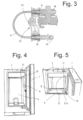
- Fig. 4 and Fig. 5 illustrate a suction hose 11 which is mounted in the upper area of the refrigerator box 4 so as to be pivotable forwards or backwards and which is freely suspended and directed downwards
- the suction hose 11 is held rotatably by a swivel drive 12 which is preferably mounted in the upper area of the refrigerator box 4 and can preferably be operated manually.
- a locking point is provided at a joint point 13 of the swivel drive 12, through which the suction hose 11 protrudes in a locked manner from the cooling chamber 5 when the refrigerator is open after the milk container 6 has been removed.
- the suction hose 11 When reinserting the milk container, the suction hose 11 is inserted through the opening 10 of the milk container 4 without touching it. As soon as the milk container is placed in the refrigerator box 4, the suction hose is directed downwards again so that its lower end extends almost to the bottom of the respective container.
- the milk container 6 can also be closed with a lid 8.
- the milk container 6 can be replaced by a cleaning container 14. This saves the additional installation space otherwise required for the cleaning container or the like, thus enabling a reduced dimensioning of the coffee machine.
- Fig. 6 shows a cleaning container 14 which is particularly suitable for this purpose and which is advantageously dimensioned with the same shape or external dimensions as the milk container 6.
- this cleaning container contains a device 15 with a water supply channel 17, a defined opening 16' for receiving a cleaning agent and an outlet opening 17'.
- the water supply channel 17 arranged in the upper part of the container is expediently guided tangentially into this cylindrical opening 16' which is accessible from above and into which at least one cleaning tablet 16 can be inserted as a soluble cleaning agent. It is preferably ring-shaped and provided with a central bore so that it can be positioned and detected with almost no play in the opening 16' by the centering pin 46.
- water is supplied from the refrigerator box 4 into the water supply channel 17 tangentially to the tablets 16, and the water with the dissolved tablet flows out through the outlet opening 17, collects in the cleaning container 14 and is from there fed into the milk module through the suction hose 11 inserted into the cleaning container.
- Fig. 7 shows schematically the working circuit of the milk module 2, which is delimited by the dashed lines 19.
- the refrigerator box 4 with the milk container 6 or the cleaning container 14 is shown with dashed lines 20.
- the suction hose 11 is connected to a heating chamber of the device 24 via a line 21a, a two-way valve 22, an air suction valve 23 and a feed pump 42, whereby the latter can also be connected to the boiler 26 and a connection valve 27 for the steam supply.
- An external water tank 28 can be connected to the boiler 26 via a filter 29 and a water pump 25.
- the cleaning container 14 is placed in the cooling chamber 5.
- the suction hose 11 therein is connected to a line 21b with the two-way valves 30 and 32, respectively. This allows the heating chamber of the device 24 and the feed pump 42 with the associated lines to be rinsed.
- plug-in coupling 33 and the outlet line 40 which leads to a cup 44 or the like on the drip tray 3" for filling with milk or milk foam.
- the connecting means for conveying the heated milk or the milk foam produced from the milk module to the outlet on the coffee machine could be provided in a way other than a plug-in coupling, such as a hose connection.
- an output line (40) for each coffee machine module could also be provided on both sides of the milk module.
Landscapes
- Engineering & Computer Science (AREA)
- Food Science & Technology (AREA)
- Apparatus For Making Beverages (AREA)
Description
- Die Erfindung betrifft ein Milchmodul zur Erzeugung von Milchschaum oder Milchgetränken, vorzugsweise zum Einbau in eine Kaffeemaschine nach dem Oberbegriff des Anspruchs 1.
- Kaffeemaschinen mit integrierten Modulen für die Erzeugung von Milchschaum bzw. zum Aufheizen von Milch werden bekanntlich in mannigfaltigen Ausführungen gebaut. Sie ermöglichen die automatische Erzeugung sowohl von Kaffee, wie Espresso, als auch von Mischgetränken aus Kaffee mit Milch oder Milchschaum, insbesondere Cappuccino. Kaffeemaschinen sind üblicherweise mit einer Reinigungseinrichtung versehen, welche im Betrieb eine periodische Reinigung der Maschine selbsttätig bewerkstelligt. Bei kleinbauenden Kaffeemaschinen ist es für den konstruktiven Aufbau schwierig, eine solche Reinigungseinrichtung vorzusehen, weil bei dem beanspruchten Raumbedarf Grenzen gesetzt sind. Eine Kaffeemaschine mit einem Reinigungsmodul ist beispielsweise in
EP2078481 A1 offenbart. - Der Erfindung liegt die Aufgabe zugrunde, diese Nachteile zu vermeiden und eine Kaffeemaschine der eingangs genannten Art zu schaffen, die bei einfachem Aufbau und leichter Handhabung die obengenannten Funktionen insbesondere betreffend die Reinigung mit möglichst reduziertem Raumbedarf ausführen kann.
- Diese Aufgabe wird erfindungsgemäss nach den Merkmalen des Anspruchs 1 gelöst.
- Erfindungsgemäss ist in dem Reinigungsbehälter eine Einrichtung mit einem Wasserzufuhrkanal, einer definierten Öffnung zur Aufnahme eines Reinigungsmittels und einer Auslassöffnung enthalten. Damit kann Wasser durch diesen Zufuhrkanal in diese Öffnung geleitet und darin das Reinigungsmittel aufgelöst, mit dem Wasser emulgiert und der Reinigungsbehälter damit gefüllt werden kann. Dies ermöglicht eine einfache Handhabung für das Reinigen und genaue Dosierung des Reinigungsmittels, wobei dazu insbesondere Reinigungstabletten verwendet werden sollen.
- Die Erfindung sieht vor, dass der Milchbehälter bzw. der Reinigungsbehälter an den Arbeitskreislauf der Maschine mittels eines im oberen Bereich der Kühlschrankbox nach vorne bzw. nach hinten schwenkbar gelagerter und nach unten frei hängender Ansaugschlauch vorgesehen ist. Die Schwenkbarkeit des Ansaugschlauchs ermöglicht das selbständige Einführen oder Entfernen desselben aus dem Behälter, ohne dass die Bedienungsperson ihn während des Umtauschvorgangs berühren muss.
- Mit Vorteil ist die Ausbildung des Milchmoduls als eine unabhängige Einheit mit diesem vorzugsweise als Steckkupplung vorgesehene Verbindungsmittel vorgesehen. Das Milchmodul kann auf einfache Weise in einem Kaffeemaschinengehäuse montiert und der Milchauslass bei dem Kaffeeauslass bewerkstelligt werden.
- Mit der erfindungsgemässen Konstruktion kann eine beträchtliche Raumeinsparung erzielt werden, weil nach Entfernen des Milchbehälters aus der Kühlschrankbox der von ihm beanspruchte Einbauraum zum Unterbringen des Reinigungsbehälters verfügbar wird, so dass für letzteren kein zusätzlicher Raumbedarf nötig ist.
- Die Erfindung ist nachfolgend anhand eines Ausführungsbeispiels unter Bezugnahme auf die Zeichnung näher erläutert. Es zeigen:
- Fig. 1
- eine perspektivisch dargestellte Kaffeemaschine mit dem Milchmodul, wobei das Kaffeemodul nicht gezeigt ist;
- Fig. 2
- eine perspektivische Seitenansicht des Milchmoduls nach
Fig. 1 ; - Fig. 3
- einen Schnitt der Steckkupplung auf der Oberseite des Milchmoduls;
- Fig. 4
- die Kühlschrankbox des Milchmoduls nach
Fig. 2 vor dem Einführen eines Behälters; - Fig. 5
- die Kühlschrankbox des Milchmoduls nach
Fig. 2 beim Einführen des Milchbehälters; - Fig. 6
- eine perspektivische Ansicht eines Reinigungsbehälters für das Milchmodul nach
Fig. 2 ; und - Fig. 7
- ein Schema des hydraulischen Kreislaufs des Milchmoduls nach
Fig. 2 . - Die in
Fig. 1 gezeigte Kaffeemaschine 1 mit einem Gehäuse 3 dient zur automatischen Erzeugung von Kaffee oder kaffeehaltigen Getränken sowie von Mischgetränken aus Kaffee mit Milch oder Milchschaum. Sie besteht aus einem Kaffeemodul zur Erzeugung von Kaffee, von dem nur gerade die Öffnungen 3' in dem Gehäuse 3 zum Einbau desselben veranschaulicht sind, und einem Milchmodul 2 zur Aufbereitung von Milch oder Milchschaum, die unabhängig voneinander in dem gemeinsamen Gehäuse 3 nebeneinander platzsparend einbaubar sind. Das Kaffeemodul 1 besteht an sich aus herkömmlichen Komponenten und ist nicht näher erläutert. Es ist einzig eine Abtropfschale 3" vorderseitig beim Gehäuse 3 gezeigt, auf welche eine Tasse oder dergleichen für das Einfüllen von Kaffee und/oder Milch bzw. Milchschaum stellbar ist. - Das in dem Gehäuse 3 einbaubare Milchmodul 2 ist mit einer Kühlschrankbox 4 ausgestattet, deren Kühlkammer 5 einen Milchbehälter 6 aufnehmen kann. Die optional abschliessbare Kühlkammer 5 ist durch eine an der Vorderseite der Maschine angeordnete Schranktür 7 leicht zugänglich. Dadurch kann nach Öffnen dieser Schranktür 7 der Milchbehälter 6 in die Kühlkammer 5 der Kühlschrankbox 4 hineingestellt oder von ihr entfernt werden. Die Kühlkammer 5 ist so ausgebildet, dass der Milchbehälter 6 annähernd spielfrei in ihr hineinpasst.
- Wie aus
Fig. 2 ersichtlich ist, ist das Milchmodul 2 erfindungsgemäss als eine unabhängige Einheit ausgebildet, welches eine mit einem Kühlaggregat 4' verbundene Kühlkammer 5 für die Aufnahme des Milchbehälters 6, eine Förderpumpe, einen Boiler 26 zur Erzeugung des Dampfs, eine Einrichtung 24 zum Erhitzen bzw. zum Erzeugen des Milchschaums sowie ein Verbindungsmittel umfasst, durch welches die erhitzte Milch bzw. der erzeugte Milchschaum durch eine Leitung zum Kaffeeauslass bei der Kaffeemaschine förderbar ist. - Ausserdem sind bei diesem Milchmodul 2 eine elektronische Kontrolleinheit 18, nicht näher erläuterte Leitungen und nicht sichtbare Steckerverbindungen an der Rückseite vorgesehen.
- Gemäss
Fig. 3 ist das Verbindungsmittel vorteilhaft als eine Steckkupplung 33 mit zwei vorzugsweise achsparallel zueinander angeordneten Steckmuffen 36, 37 gebildet, in welche die Zu- bzw. Ausgangsleitung 39, 40 dichtend und totraumoptimiert einsteckbar sind. Die eine Steckmuffe 36, 37 ist vorstehend zu einem die Kühlschrankbox 4 umgebenden Einschubgehäuse 2' angeordnet, an welche die Ausgangsleitung 40 in der Kaffeemaschine 1 koppelbar ist. - Die Steckkupplung 33 weist ein Verbindungsstück 35 auf, das an beiden Enden mit je einer Steckmuffe 36 bzw. 37 versehen ist, wobei das Verbindungsstück 35 bei dem Gehäuse 3 befestigt ist. Rückseitig sind diese Steckmuffen vorzugsweise mit einem Schlauchbogen 41 verbunden.
- Nachdem das Milchmodul in dem Gehäuse 3 eingebaut ist, ist es lediglich erforderlich, die Ausgangsleitung 40 mit der Steckmuffe 36 zu koppeln. Die Steckkupplung 33 zeichnet sich durch einen sehr einfachen Aufbau und eine sichere Handhabung aus. Selbstverständlich können aber hierfür auch andere Kupplungsarten in Frage kommen.
-
Fig. 4 und Fig. 5 verdeutlichen einen erfindungsgemäss im oberen Bereich der Kühlschrankbox 4 nach vorne bzw. nach hinten schwenkbar gelagerten Ansaugschlauch 11, der frei hängend nach unten ausgerichtet ist,
Der Ansaugschlauch 11 ist durch einen im vorzugsweise oberen Bereich der Kühlschrankbox 4 gelagerten und vorzugsweise manuell betätigbaren Schwenkantrieb 12 drehbar gehalten. Dazu ist bei einer Gelenkstelle 13 des Schwenkantriebs 12 eine Einraststelle vorgesehen, durch diese der Ansaugschlauch 11 bei offenem Kühlschrank nach Entfernen des Milchbehälters 6 aus der Kühlkammer 5 arretiert herausragt. In dieser nach vorne geschwenkten Position 11' kann der Ansaugschlauch von oben in den Milchbehälter 6 bzw. in einen Reinigungsbehälter 14 beim Hineinstellen in die Kühlkammer 5 eingeführt werden, Damit ist dieser Ansaugschlauch platzsparend in der Kühlkammer 5 integriert. - Beim Wiedereinsetzen des Milchbehälters wird der Ansaugschlauch 11 durch die Öffnung 10 des Milchbehälters 4 ohne ihn zu berühren eingeführt. Sobald der Milchbehälter in die Kühlschrankbox 4 hineingestellt ist, ist der Ansaugschlauch wieder nach unten gerichtet, damit er sich mit seinem unteren Ende annähernd bis zum jeweiligen Behälterboden erstreckt. Der Milchbehälter 6 ist ferner durch einen Deckel 8 verschliessbar.
- Der Milchbehälter 6 kann im Rahmen der Erfindung durch einen Reinigungsbehälter 14 ausgetauscht werden. Dadurch kann der sonst für den Reinigungsbehälter oder ähnlichem erforderliche zusätzliche Einbauraum eingespart werden und damit ist eine reduzierte Dimensionierung der Kaffeemaschine ermöglicht.
-
Fig. 6 zeigt einen dafür besonders geeigneten Reinigungsbehälter 14, der vorteilhaft mit derselben Form bzw. Aussenabmessungen wie der Milchbehälter 6 dimensioniert ist. Im Unterschied zu diesem ist aber in diesem Reinigungsbehälter eine Einrichtung 15 mit einem Wasserzufuhrkanal 17, einer definierten Öffnung 16' zur Aufnahme eines Reinigungsmittels und einer Auslassöffnung 17' enthalten. - Zweckmässigerweise ist der im oberen Teil des Behälters angeordnete Wasserzufuhrkanal 17 tangential in diese zylindrisch ausgebildete, von oben zugängliche Öffnung 16' geführt, in welcher zumindest eine Reinigungstablette 16 als lösliches Reinigungsmittels einlegbar ist. Vorzugsweise ist sie ringförmig ausgebildet und mit einer mittleren Bohrung versehen, so dass sie durch den Zentrierstift 46 in der Öffnung 16' annähernd spielfrei positionierbar und detektierbar ist.
- Zum Auflösen der Tabletten wird Wasser von der Kühlschrankbox 4 in den Wasserzufuhrkanal 17 tangential auf die Tabletten 16 zugeführt, und das Wasser mit der aufgelösten Tablette läuft durch die Auslassöffnung 17 heraus, sammelt sich im Reinigungsbehälter 14 und wird von dort durch den in den Reinigungsbehälter eingeführten Ansaugschlauch 11 in das Milchmodul geleitet.
-
Fig. 7 zeigt schematisch den Arbeitskreislauf des Milchmoduls 2, welche durch die gestrichelten Linien 19 abgegrenzt ist. Darin ist die Kühlschrankbox 4 mit dem Milchbehälter 6 bzw. dem Reinigungsbehälter 14 mit gestrichelten Linien 20 verdeutlicht. Für die Milchzufuhr ist der Ansaugschlauch 11 via eine Leitung 21a, ein Zweiwegventil 22, ein Luftansaugventil 23 sowie eine Förderpumpe 42 mit einer Heizkammer der Einrichtung 24 verbunden, wobei letztere für die Dampfzufuhr auch mit dem Boiler 26 und einem Zuschaltventil 27 verbindbar ist. Ein externer Wassertank 28 ist über ein Filter 29 mit dem Boiler 26 via eine Wasserpumpe 25 verbindbar. - Für den periodischen Reinigungsvorgang des Milchmoduls 2 ist der Reinigungsbehälter 14 in die Kühlkammer 5 hineingestellt. Der Ansaugschlauch 11 darin ist an eine Leitung 21b mit den Zweiwegventilen 30 bzw. 32 angeschlossen. Damit können die Heizkammer der Einrichtung 24 und die Förderpumpe 42 mit den zugehörigen Leitungen gespült werden.
- Es ist ferner noch die Steckkupplung 33 und die Ausgangsleitung 40 gezeigt, welche zu einer Tasse 44 oder dergleichen auf der Abtropfschale 3" für das Einfüllen von Milch bzw. Milchschaum führt.
- Die Erfindung ist mit dem oben erläuterten Ausführungsbeispiel ausreichend dargetan. Sie könnte aber selbstverständlich noch durch andere Varianten offenbart sein. So könnte das Verbindungsmittel zur Weiterleitung der erhitzten Milch bzw. des erzeugten Milchschaums vom Milchmodul zum Auslass bei der Kaffeemaschine anders als durch eine Steckkupplung vorgesehen sein, wie beispielsweise durch eine Schlauchverbindung. Im Prinzip könnte auch beidseitig zum Milchmodul je eine Ausgangsleitung (40) für je ein Kaffeemaschinenmodul vorgesehen sein.
Claims (9)
- Milchmodul zur Erzeugung von Milchschaum oder Milchgetränken, vorzugsweise zum Einbau in eine Kaffeemaschine, mit einem Milchbehälter (6), einer Förderpumpe und einer Einrichtung (24) zum Erhitzen der Milch bzw. zum Erzeugen des Milchschaums oder von sonstigen Milchgetränken, wobei ein Reinigungssystem in dem vorzugsweise als eine unabhängige Einheit ausgebildeten Milchmodul integriert ist, mittels welchem insbesondere durch die Förderpumpe (42), die Einrichtung (24) zum Erhitzen bzw. zum Erzeugen des Milchschaums sowie die Zu- bzw. Ausgangsleitung (39, 40) ein Reinigungsvorgang ermöglicht wird, zu diesem Zwecke anstelle des Milchbehälters (6) ein Reinigungsbehälter (14) mit einem Reinigungsmittel in die Kühlkammer (5) hineinstellbar ist, dadurch gekennzeichnet, dass in dem Reinigungsbehälter (14) eine Einrichtung (15) mit einem Wasserzufuhrkanal (17), eine definierte Öffnung (16') zur Aufnahme eines Reinigungsmittels, insbesondere einer Tablette, und eine Auslassöffnung (17') enthalten ist, mittels der Wasser durch diesen Zufuhrkanal (17) in diese Öffnung (16') leitbar und darin das Reinigungsmittel, insbesondere die Tablette, aufgelöst und mit dem Wasser emulgiert via die Auslassöffnung (17') in den Reinigungsbehälter (14) einströmbar ist.
- Milchmodul nach Anspruch 1, dadurch gekennzeichnet, dass der Wasserzufuhrkanal (17) tangential in diese zylindrisch ausgebildete Öffnung (16') geführt ist, in welcher zumindest eine Reinigungstablette (16) als lösliches Reinigungsmittel positionierbar und detektierbar ist.
- Milchmodul nach Anspruch 1 oder 2, dadurch gekennzeichnet, dass
ein im Bereich der Kühlschrankbox (4) nach vorne bzw. nach hinten schwenkbar gelagerter und nach unten frei hängender Ansaugschlauch (11) vorgesehen ist, der in der nach vorne geschwenkten Position (11') von oben in den Milchbehälter (6) bzw. in den Reinigungsbehälter (14) beim Hineinstellen desselben berührungslos einführbar ist. - Milchmodul nach Anspruch 3, dadurch gekennzeichnet, dass
der Ansaugschlauch (11) durch einen im Bereich der Kühlschrankbox (4) gelagerten und vorzugsweise manuell betätigbaren Schwenkantrieb (12) drehbar ist. - Milchmodul nach Anspruch 4, dadurch gekennzeichnet, dass
der Schwenkantrieb (12) an seiner Gelenkstelle (13) mit einer Einraststelle versehen ist, in welcher der Ansaugschlauch (11) nach Entfernen des Milchbehälters (6) bzw. des Reinigungsbehälters (14) nach vorne aus der Kühlschrankbox (4) arretiert in einer Position (11') herausragt. - Milchmodul nach Anspruch 4 oder 5, dadurch gekennzeichnet, dass
der Ansaugschlauch (11) durch den Schwenkantrieb (12) beim Hineinstellen des Milchbehälters (6) bzw. Reinigungsbehälters (14) in die Kühlschrankbox (4) einschwenkt, bis er wieder nach unten gerichtet ist, damit er sich mit seinem unteren Ende annähernd bis zum jeweiligen Behälterboden erstreckt. - Milchmodul nach einem der Ansprüche 1 bis 6, dadurch gekennzeichnet, dass
das Milchmodul (2) als eine unabhängige Einheit ausgebildet ist und ein Verbindungsmittel umfasst, durch welches die erhitzte Milch bzw. der erzeugte Milchschaum durch wenigstens eine Ausgangsleitung (40) zum Kaffeeauslass bei der Kaffeemaschine förderbar ist. - Milchmodul nach Anspruch 7, dadurch gekennzeichnet, dass
das Verbindungsmittel durch eine Steckkupplung (33) mit zwei vorzugsweise achsparallel zueinander angeordneten Steckmuffen (36, 37) gebildet ist, in welche die Zu- bzw. Ausgangsleitung (39, 40) dichtend einsteckbar sind. - Milchmodul nach Anspruch 8, dadurch gekennzeichnet, dass
die eine Steckmuffe (36, 37) vorstehend zu einem die Kühlschrankbox (4) umgebenden Einschubgehäuse (2') angeordnet ist, an welche die Ausgangsleitung (40) in der Kaffeemaschine (1) koppelbar ist.
Applications Claiming Priority (3)
| Application Number | Priority Date | Filing Date | Title |
|---|---|---|---|
| CH00875/17A CH713954A1 (de) | 2017-07-06 | 2017-07-06 | Milchmodul zur Erzeugung von Milchschaum oder Milchgetränken, vorzugsweise zum Einbau in eine Kaffeemaschine. |
| EP18732278.9A EP3648642B1 (de) | 2017-07-06 | 2018-06-08 | Milchmodul zur erzeugung von milchschaum oder milchgetränken, vorzugsweise zum einbau in eine kaffeemaschine |
| PCT/EP2018/065123 WO2019007629A1 (de) | 2017-07-06 | 2018-06-08 | Milchmodul zur erzeugung von milchschaum oder milchgetränken, vorzugsweise zum einbau in eine kaffeemaschine |
Related Parent Applications (1)
| Application Number | Title | Priority Date | Filing Date |
|---|---|---|---|
| EP18732278.9A Division EP3648642B1 (de) | 2017-07-06 | 2018-06-08 | Milchmodul zur erzeugung von milchschaum oder milchgetränken, vorzugsweise zum einbau in eine kaffeemaschine |
Publications (3)
| Publication Number | Publication Date |
|---|---|
| EP4282309A2 EP4282309A2 (de) | 2023-11-29 |
| EP4282309A3 EP4282309A3 (de) | 2024-01-10 |
| EP4282309B1 true EP4282309B1 (de) | 2025-01-29 |
Family
ID=62683172
Family Applications (2)
| Application Number | Title | Priority Date | Filing Date |
|---|---|---|---|
| EP23203312.6A Active EP4282309B1 (de) | 2017-07-06 | 2018-06-08 | Milchmodul zur erzeugung von milchschaum oder milchgetränken, vorzugsweise zum einbau in eine kaffeemaschine |
| EP18732278.9A Active EP3648642B1 (de) | 2017-07-06 | 2018-06-08 | Milchmodul zur erzeugung von milchschaum oder milchgetränken, vorzugsweise zum einbau in eine kaffeemaschine |
Family Applications After (1)
| Application Number | Title | Priority Date | Filing Date |
|---|---|---|---|
| EP18732278.9A Active EP3648642B1 (de) | 2017-07-06 | 2018-06-08 | Milchmodul zur erzeugung von milchschaum oder milchgetränken, vorzugsweise zum einbau in eine kaffeemaschine |
Country Status (4)
| Country | Link |
|---|---|
| EP (2) | EP4282309B1 (de) |
| CH (1) | CH713954A1 (de) |
| PL (2) | PL3648642T3 (de) |
| WO (1) | WO2019007629A1 (de) |
Families Citing this family (2)
| Publication number | Priority date | Publication date | Assignee | Title |
|---|---|---|---|---|
| JP7393950B2 (ja) | 2017-07-06 | 2023-12-07 | シュタイナー・アーゲー・ウェギス | ミルクフォームまたはミルク飲料を生成するための、好ましくはコーヒーマシンに設置するためのミルクモジュール |
| DE102023206940A1 (de) * | 2023-07-21 | 2025-01-23 | BSH Hausgeräte GmbH | Vorratsbehälter für Reinigungsmittel und Kaffeeautomat |
Family Cites Families (15)
| Publication number | Priority date | Publication date | Assignee | Title |
|---|---|---|---|---|
| US5473972A (en) * | 1994-10-24 | 1995-12-12 | Conair Corporation | Milk container attachment for cappucino maker |
| US7021206B2 (en) * | 2002-06-18 | 2006-04-04 | Eckenhausen Roland B | Hot dairy-based beverage dispenser |
| CA2493904A1 (en) * | 2002-07-09 | 2004-01-15 | The Coca-Cola Company | System and method for producing foamed and steamed milk for hot beverages |
| DE102006047969A1 (de) * | 2006-10-11 | 2008-04-17 | Niro-Plan Ag | Vorrichtung zur Zubereitung und Ausgabe von Getränken mit Reinigungseinrichtung |
| DK2011421T3 (da) * | 2007-07-05 | 2010-11-08 | Schaerer Ag | Apparat til udskænkning af mælkebaserede drikke |
| DE102008003733B4 (de) * | 2008-01-10 | 2022-12-01 | Franke Kaffeemaschinen Ag | Reinigungsmodul, Vorrichtung und Verfahren zur Reinigung für Maschinen zur Herstellung flüssiger Lebensmittel |
| ES2392011T3 (es) * | 2009-03-03 | 2012-12-03 | Delica Ag | Dispositivo para la preparación de espuma de leche |
| EP2272408A1 (de) * | 2009-07-08 | 2011-01-12 | Jura Elektroapparate AG | Getränkebereitungsmaschine und Verfahren zum Reinigen einer Getränkebereitungsmaschine |
| CN201798512U (zh) * | 2010-07-12 | 2011-04-20 | 黄绪波 | 一种免泡米智能电饭煲 |
| EP2474254A1 (de) * | 2011-01-07 | 2012-07-11 | Nestec S.A. | Modulares Getränkeausgabesystem |
| CH705198B1 (de) * | 2011-06-30 | 2020-04-30 | Steiner Ag Weggis | Reinigungssystem für eine Kaffeemaschine. |
| CH706370B1 (de) * | 2012-04-05 | 2016-02-29 | Schaerer Ag | Verfahren zum Reinigen der mit Milch beaufschlagten Leitungswege einer Kaffeemaschine sowie Milcheinheit zur Durchführung des Verfahrens. |
| FR3021197B1 (fr) * | 2014-05-23 | 2016-05-13 | Seb Sa | Dispositif de production de boissons a base de lait muni de moyens de securite et machine a cafe comportant un tel dispositif |
| EP3000365A1 (de) * | 2014-09-24 | 2016-03-30 | Qbo Coffee GmbH | Milchschäumergerät |
| CN204120829U (zh) * | 2014-09-28 | 2015-01-28 | 广东亿龙电器科技有限公司 | 一种咖啡机 |
-
2017
- 2017-07-06 CH CH00875/17A patent/CH713954A1/de unknown
-
2018
- 2018-06-08 PL PL18732278.9T patent/PL3648642T3/pl unknown
- 2018-06-08 EP EP23203312.6A patent/EP4282309B1/de active Active
- 2018-06-08 EP EP18732278.9A patent/EP3648642B1/de active Active
- 2018-06-08 WO PCT/EP2018/065123 patent/WO2019007629A1/de not_active Ceased
- 2018-06-08 PL PL23203312.6T patent/PL4282309T3/pl unknown
Also Published As
| Publication number | Publication date |
|---|---|
| EP4282309A2 (de) | 2023-11-29 |
| WO2019007629A1 (de) | 2019-01-10 |
| EP3648642A1 (de) | 2020-05-13 |
| PL4282309T3 (pl) | 2025-05-26 |
| PL3648642T3 (pl) | 2024-03-25 |
| EP4282309A3 (de) | 2024-01-10 |
| CH713954A1 (de) | 2019-01-15 |
| EP3648642B1 (de) | 2023-10-18 |
Similar Documents
| Publication | Publication Date | Title |
|---|---|---|
| EP3451892B1 (de) | Flaschenspülkorbvorrichtung sowie geschirrspülmaschine mit einer solchen vorrichtung | |
| EP0154206B1 (de) | Vorrichtung zur Zubereitung von Heissgetränken | |
| DE102010007143B4 (de) | Kaffeemaschine mit einer Schäumvorrichtung und Mitteln zum Reinigen der Schäumvorrichtung und einer Milchansaugleitung sowie Verfahren zum Spülen der Milchansaugleitung | |
| EP2078481B1 (de) | Reinigungsmodul, Vorrichtung und Verfahren zur Reinigung für Maschinen zur Herstellung flüssiger Lebensmittel | |
| EP2589322B1 (de) | Kaffeemaschine, insbesondere Espressovollautomat | |
| EP2768360B1 (de) | Kafeemaschine, insbesondere kaffeevollautomat sowie verfahren zum betreiben einer kaffeemaschine | |
| EP2203094B1 (de) | Kaffeemaschine | |
| EP2424411B1 (de) | Vorrichtung zum bereitstellen von milch für eine kaffeemaschine | |
| EP2807964B1 (de) | Milchaufschäumvorrichtung, Kaffeemaschine, System sowie Reinigungsverfahren | |
| EP3648642B1 (de) | Milchmodul zur erzeugung von milchschaum oder milchgetränken, vorzugsweise zum einbau in eine kaffeemaschine | |
| DE102021133520B4 (de) | Reinigungsvorrichtung für eine Getränkezubereitungsmaschine und Verfahren zur Reinigung einer Getränkezubereitungsmaschine | |
| AU2018298273A1 (en) | Milk module for generating milk foam or milk beverages, preferably for installing into a coffee machine | |
| EP3811830B1 (de) | Getränkeautomat | |
| EP3369352B1 (de) | Getränkezubereitungsvorrichtung | |
| DE102021101271A1 (de) | Getränkezubereitungsvorrichtung, Getränkeautomat und Verfahren zum Zubereiten eines Getränks | |
| DE102020119975A1 (de) | Verfahren zum Reinigen einer Vorrichtung zum Zufügen von Getränkezusätzen für einen Getränkeautomaten, insbesondere einer Kaffeemaschine | |
| DE102021203146B3 (de) | Kaffeeautomat und Reinigungsvorrichtung | |
| EP3025624B1 (de) | Kaffeeautomat | |
| EP0544072A1 (de) | Vorrichtung zum Abfüllen und Dosieren von Reinigungsmitteln | |
| EP2219502B1 (de) | Getränkebereiter mit einem milchbehälter | |
| DE102006013367A1 (de) | Verfahren und Vorrichtung zum Reinigen einer Becherfüllmaschine | |
| DE8905974U1 (de) | Reinigungsvorrichtung für medizinische und pharmazeutische Geräte und Kleinteile |
Legal Events
| Date | Code | Title | Description |
|---|---|---|---|
| PUAI | Public reference made under article 153(3) epc to a published international application that has entered the european phase |
Free format text: ORIGINAL CODE: 0009012 |
|
| STAA | Information on the status of an ep patent application or granted ep patent |
Free format text: STATUS: THE APPLICATION HAS BEEN PUBLISHED |
|
| AC | Divisional application: reference to earlier application |
Ref document number: 3648642 Country of ref document: EP Kind code of ref document: P |
|
| AK | Designated contracting states |
Kind code of ref document: A2 Designated state(s): AL AT BE BG CH CY CZ DE DK EE ES FI FR GB GR HR HU IE IS IT LI LT LU LV MC MK MT NL NO PL PT RO RS SE SI SK SM TR |
|
| REG | Reference to a national code |
Ref country code: DE Free format text: PREVIOUS MAIN CLASS: A47J0031460000 Ref country code: DE Ref legal event code: R079 Ref document number: 502018015545 Country of ref document: DE Free format text: PREVIOUS MAIN CLASS: A47J0031460000 Ipc: A47J0031440000 |
|
| PUAL | Search report despatched |
Free format text: ORIGINAL CODE: 0009013 |
|
| AK | Designated contracting states |
Kind code of ref document: A3 Designated state(s): AL AT BE BG CH CY CZ DE DK EE ES FI FR GB GR HR HU IE IS IT LI LT LU LV MC MK MT NL NO PL PT RO RS SE SI SK SM TR |
|
| RIC1 | Information provided on ipc code assigned before grant |
Ipc: A47J 31/46 20060101ALI20231207BHEP Ipc: A47J 31/60 20060101ALI20231207BHEP Ipc: A47J 31/44 20060101AFI20231207BHEP |
|
| STAA | Information on the status of an ep patent application or granted ep patent |
Free format text: STATUS: REQUEST FOR EXAMINATION WAS MADE |
|
| 17P | Request for examination filed |
Effective date: 20240627 |
|
| RBV | Designated contracting states (corrected) |
Designated state(s): AL AT BE BG CH CY CZ DE DK EE ES FI FR GB GR HR HU IE IS IT LI LT LU LV MC MK MT NL NO PL PT RO RS SE SI SK SM TR |
|
| GRAP | Despatch of communication of intention to grant a patent |
Free format text: ORIGINAL CODE: EPIDOSNIGR1 |
|
| STAA | Information on the status of an ep patent application or granted ep patent |
Free format text: STATUS: GRANT OF PATENT IS INTENDED |
|
| INTG | Intention to grant announced |
Effective date: 20240925 |
|
| GRAS | Grant fee paid |
Free format text: ORIGINAL CODE: EPIDOSNIGR3 |
|
| GRAA | (expected) grant |
Free format text: ORIGINAL CODE: 0009210 |
|
| STAA | Information on the status of an ep patent application or granted ep patent |
Free format text: STATUS: THE PATENT HAS BEEN GRANTED |
|
| AC | Divisional application: reference to earlier application |
Ref document number: 3648642 Country of ref document: EP Kind code of ref document: P |
|
| AK | Designated contracting states |
Kind code of ref document: B1 Designated state(s): AL AT BE BG CH CY CZ DE DK EE ES FI FR GB GR HR HU IE IS IT LI LT LU LV MC MK MT NL NO PL PT RO RS SE SI SK SM TR |
|
| REG | Reference to a national code |
Ref country code: GB Ref legal event code: FG4D Free format text: NOT ENGLISH |
|
| REG | Reference to a national code |
Ref country code: CH Ref legal event code: EP |
|
| REG | Reference to a national code |
Ref country code: DE Ref legal event code: R096 Ref document number: 502018015545 Country of ref document: DE |
|
| REG | Reference to a national code |
Ref country code: IE Ref legal event code: FG4D Free format text: LANGUAGE OF EP DOCUMENT: GERMAN |
|
| REG | Reference to a national code |
Ref country code: NL Ref legal event code: MP Effective date: 20250129 |
|
| PG25 | Lapsed in a contracting state [announced via postgrant information from national office to epo] |
Ref country code: NL Free format text: LAPSE BECAUSE OF FAILURE TO SUBMIT A TRANSLATION OF THE DESCRIPTION OR TO PAY THE FEE WITHIN THE PRESCRIBED TIME-LIMIT Effective date: 20250129 |
|
| REG | Reference to a national code |
Ref country code: SK Ref legal event code: T3 Ref document number: E 46339 Country of ref document: SK |
|
| PG25 | Lapsed in a contracting state [announced via postgrant information from national office to epo] |
Ref country code: RS Free format text: LAPSE BECAUSE OF FAILURE TO SUBMIT A TRANSLATION OF THE DESCRIPTION OR TO PAY THE FEE WITHIN THE PRESCRIBED TIME-LIMIT Effective date: 20250429 |
|
| PG25 | Lapsed in a contracting state [announced via postgrant information from national office to epo] |
Ref country code: FI Free format text: LAPSE BECAUSE OF FAILURE TO SUBMIT A TRANSLATION OF THE DESCRIPTION OR TO PAY THE FEE WITHIN THE PRESCRIBED TIME-LIMIT Effective date: 20250129 |
|
| PGFP | Annual fee paid to national office [announced via postgrant information from national office to epo] |
Ref country code: DE Payment date: 20250618 Year of fee payment: 8 Ref country code: PL Payment date: 20250513 Year of fee payment: 8 |
|
| PG25 | Lapsed in a contracting state [announced via postgrant information from national office to epo] |
Ref country code: ES Free format text: LAPSE BECAUSE OF FAILURE TO SUBMIT A TRANSLATION OF THE DESCRIPTION OR TO PAY THE FEE WITHIN THE PRESCRIBED TIME-LIMIT Effective date: 20250129 |
|
| PGFP | Annual fee paid to national office [announced via postgrant information from national office to epo] |
Ref country code: GB Payment date: 20250508 Year of fee payment: 8 |
|
| REG | Reference to a national code |
Ref country code: LT Ref legal event code: MG9D |
|
| PG25 | Lapsed in a contracting state [announced via postgrant information from national office to epo] |
Ref country code: IS Free format text: LAPSE BECAUSE OF FAILURE TO SUBMIT A TRANSLATION OF THE DESCRIPTION OR TO PAY THE FEE WITHIN THE PRESCRIBED TIME-LIMIT Effective date: 20250529 Ref country code: NO Free format text: LAPSE BECAUSE OF FAILURE TO SUBMIT A TRANSLATION OF THE DESCRIPTION OR TO PAY THE FEE WITHIN THE PRESCRIBED TIME-LIMIT Effective date: 20250429 |
|
| PG25 | Lapsed in a contracting state [announced via postgrant information from national office to epo] |
Ref country code: HR Free format text: LAPSE BECAUSE OF FAILURE TO SUBMIT A TRANSLATION OF THE DESCRIPTION OR TO PAY THE FEE WITHIN THE PRESCRIBED TIME-LIMIT Effective date: 20250129 |
|
| PG25 | Lapsed in a contracting state [announced via postgrant information from national office to epo] |
Ref country code: LV Free format text: LAPSE BECAUSE OF FAILURE TO SUBMIT A TRANSLATION OF THE DESCRIPTION OR TO PAY THE FEE WITHIN THE PRESCRIBED TIME-LIMIT Effective date: 20250129 Ref country code: PT Free format text: LAPSE BECAUSE OF FAILURE TO SUBMIT A TRANSLATION OF THE DESCRIPTION OR TO PAY THE FEE WITHIN THE PRESCRIBED TIME-LIMIT Effective date: 20250529 |
|
| PGFP | Annual fee paid to national office [announced via postgrant information from national office to epo] |
Ref country code: FR Payment date: 20250618 Year of fee payment: 8 |
|
| PG25 | Lapsed in a contracting state [announced via postgrant information from national office to epo] |
Ref country code: BG Free format text: LAPSE BECAUSE OF FAILURE TO SUBMIT A TRANSLATION OF THE DESCRIPTION OR TO PAY THE FEE WITHIN THE PRESCRIBED TIME-LIMIT Effective date: 20250129 Ref country code: GR Free format text: LAPSE BECAUSE OF FAILURE TO SUBMIT A TRANSLATION OF THE DESCRIPTION OR TO PAY THE FEE WITHIN THE PRESCRIBED TIME-LIMIT Effective date: 20250430 |
|
| PGFP | Annual fee paid to national office [announced via postgrant information from national office to epo] |
Ref country code: AT Payment date: 20250627 Year of fee payment: 8 |
|
| PGFP | Annual fee paid to national office [announced via postgrant information from national office to epo] |
Ref country code: TR Payment date: 20250508 Year of fee payment: 8 Ref country code: SK Payment date: 20250509 Year of fee payment: 8 |
|
| PGFP | Annual fee paid to national office [announced via postgrant information from national office to epo] |
Ref country code: CZ Payment date: 20250509 Year of fee payment: 8 |
|
| PG25 | Lapsed in a contracting state [announced via postgrant information from national office to epo] |
Ref country code: SE Free format text: LAPSE BECAUSE OF FAILURE TO SUBMIT A TRANSLATION OF THE DESCRIPTION OR TO PAY THE FEE WITHIN THE PRESCRIBED TIME-LIMIT Effective date: 20250129 |
|
| PG25 | Lapsed in a contracting state [announced via postgrant information from national office to epo] |
Ref country code: SM Free format text: LAPSE BECAUSE OF FAILURE TO SUBMIT A TRANSLATION OF THE DESCRIPTION OR TO PAY THE FEE WITHIN THE PRESCRIBED TIME-LIMIT Effective date: 20250129 |
|
| PG25 | Lapsed in a contracting state [announced via postgrant information from national office to epo] |
Ref country code: DK Free format text: LAPSE BECAUSE OF FAILURE TO SUBMIT A TRANSLATION OF THE DESCRIPTION OR TO PAY THE FEE WITHIN THE PRESCRIBED TIME-LIMIT Effective date: 20250129 |
|
| PGFP | Annual fee paid to national office [announced via postgrant information from national office to epo] |
Ref country code: IT Payment date: 20250612 Year of fee payment: 8 |
|
| PG25 | Lapsed in a contracting state [announced via postgrant information from national office to epo] |
Ref country code: EE Free format text: LAPSE BECAUSE OF FAILURE TO SUBMIT A TRANSLATION OF THE DESCRIPTION OR TO PAY THE FEE WITHIN THE PRESCRIBED TIME-LIMIT Effective date: 20250129 |
|
| PG25 | Lapsed in a contracting state [announced via postgrant information from national office to epo] |
Ref country code: RO Free format text: LAPSE BECAUSE OF FAILURE TO SUBMIT A TRANSLATION OF THE DESCRIPTION OR TO PAY THE FEE WITHIN THE PRESCRIBED TIME-LIMIT Effective date: 20250129 |
|
| REG | Reference to a national code |
Ref country code: DE Ref legal event code: R097 Ref document number: 502018015545 Country of ref document: DE |
|
| PLBE | No opposition filed within time limit |
Free format text: ORIGINAL CODE: 0009261 |
|
| STAA | Information on the status of an ep patent application or granted ep patent |
Free format text: STATUS: NO OPPOSITION FILED WITHIN TIME LIMIT |
|
| REG | Reference to a national code |
Ref country code: CH Ref legal event code: L10 Free format text: ST27 STATUS EVENT CODE: U-0-0-L10-L00 (AS PROVIDED BY THE NATIONAL OFFICE) Effective date: 20251210 |
|
| 26N | No opposition filed |
Effective date: 20251030 |
|
| REG | Reference to a national code |
Ref country code: CH Ref legal event code: H13 Free format text: ST27 STATUS EVENT CODE: U-0-0-H10-H13 (AS PROVIDED BY THE NATIONAL OFFICE) Effective date: 20260127 |
|
| PG25 | Lapsed in a contracting state [announced via postgrant information from national office to epo] |
Ref country code: MC Free format text: LAPSE BECAUSE OF FAILURE TO SUBMIT A TRANSLATION OF THE DESCRIPTION OR TO PAY THE FEE WITHIN THE PRESCRIBED TIME-LIMIT Effective date: 20250129 |
|
| REG | Reference to a national code |
Ref country code: CH Ref legal event code: K11 Free format text: ST27 STATUS EVENT CODE: U-0-0-K10-K11 (AS PROVIDED BY THE NATIONAL OFFICE) Effective date: 20260203 Ref country code: CH Ref legal event code: U11 Free format text: ST27 STATUS EVENT CODE: U-0-0-U10-U11 (AS PROVIDED BY THE NATIONAL OFFICE) Effective date: 20260203 |
|
| PG25 | Lapsed in a contracting state [announced via postgrant information from national office to epo] |
Ref country code: LU Free format text: LAPSE BECAUSE OF NON-PAYMENT OF DUE FEES Effective date: 20250608 |
|
| REG | Reference to a national code |
Ref country code: BE Ref legal event code: MM Effective date: 20250630 |
|
| PG25 | Lapsed in a contracting state [announced via postgrant information from national office to epo] |
Ref country code: IE Free format text: LAPSE BECAUSE OF NON-PAYMENT OF DUE FEES Effective date: 20250608 |
|
| PG25 | Lapsed in a contracting state [announced via postgrant information from national office to epo] |
Ref country code: BE Free format text: LAPSE BECAUSE OF NON-PAYMENT OF DUE FEES Effective date: 20250630 |
|
| PGFP | Annual fee paid to national office [announced via postgrant information from national office to epo] |
Ref country code: CH Payment date: 20260203 Year of fee payment: 8 |