EP4282102B1 - Neue datenindikatorhandhabung für harq-übertragungen während eines c-drx-modus - Google Patents
Neue datenindikatorhandhabung für harq-übertragungen während eines c-drx-modus Download PDFInfo
- Publication number
- EP4282102B1 EP4282102B1 EP21701733.4A EP21701733A EP4282102B1 EP 4282102 B1 EP4282102 B1 EP 4282102B1 EP 21701733 A EP21701733 A EP 21701733A EP 4282102 B1 EP4282102 B1 EP 4282102B1
- Authority
- EP
- European Patent Office
- Prior art keywords
- harq
- ndi
- base station
- measurement gap
- transmission
- Prior art date
- Legal status (The legal status is an assumption and is not a legal conclusion. Google has not performed a legal analysis and makes no representation as to the accuracy of the status listed.)
- Active
Links
Images


Classifications
-
- H—ELECTRICITY
- H04—ELECTRIC COMMUNICATION TECHNIQUE
- H04L—TRANSMISSION OF DIGITAL INFORMATION, e.g. TELEGRAPHIC COMMUNICATION
- H04L1/00—Arrangements for detecting or preventing errors in the information received
- H04L1/12—Arrangements for detecting or preventing errors in the information received by using return channel
- H04L1/16—Arrangements for detecting or preventing errors in the information received by using return channel in which the return channel carries supervisory signals, e.g. repetition request signals
- H04L1/18—Automatic repetition systems, e.g. Van Duuren systems
- H04L1/1867—Arrangements specially adapted for the transmitter end
- H04L1/1887—Scheduling and prioritising arrangements
-
- H—ELECTRICITY
- H04—ELECTRIC COMMUNICATION TECHNIQUE
- H04L—TRANSMISSION OF DIGITAL INFORMATION, e.g. TELEGRAPHIC COMMUNICATION
- H04L1/00—Arrangements for detecting or preventing errors in the information received
- H04L1/12—Arrangements for detecting or preventing errors in the information received by using return channel
- H04L1/16—Arrangements for detecting or preventing errors in the information received by using return channel in which the return channel carries supervisory signals, e.g. repetition request signals
- H04L1/18—Automatic repetition systems, e.g. Van Duuren systems
- H04L1/1812—Hybrid protocols; Hybrid automatic repeat request [HARQ]
- H04L1/1819—Hybrid protocols; Hybrid automatic repeat request [HARQ] with retransmission of additional or different redundancy
-
- H—ELECTRICITY
- H04—ELECTRIC COMMUNICATION TECHNIQUE
- H04L—TRANSMISSION OF DIGITAL INFORMATION, e.g. TELEGRAPHIC COMMUNICATION
- H04L1/00—Arrangements for detecting or preventing errors in the information received
- H04L1/12—Arrangements for detecting or preventing errors in the information received by using return channel
- H04L1/16—Arrangements for detecting or preventing errors in the information received by using return channel in which the return channel carries supervisory signals, e.g. repetition request signals
- H04L1/18—Automatic repetition systems, e.g. Van Duuren systems
- H04L1/1829—Arrangements specially adapted for the receiver end
- H04L1/1848—Time-out mechanisms
- H04L1/1851—Time-out mechanisms using multiple timers
-
- H—ELECTRICITY
- H04—ELECTRIC COMMUNICATION TECHNIQUE
- H04L—TRANSMISSION OF DIGITAL INFORMATION, e.g. TELEGRAPHIC COMMUNICATION
- H04L1/00—Arrangements for detecting or preventing errors in the information received
- H04L1/12—Arrangements for detecting or preventing errors in the information received by using return channel
- H04L1/16—Arrangements for detecting or preventing errors in the information received by using return channel in which the return channel carries supervisory signals, e.g. repetition request signals
- H04L1/18—Automatic repetition systems, e.g. Van Duuren systems
- H04L1/1829—Arrangements specially adapted for the receiver end
- H04L1/1864—ARQ related signaling
-
- H—ELECTRICITY
- H04—ELECTRIC COMMUNICATION TECHNIQUE
- H04L—TRANSMISSION OF DIGITAL INFORMATION, e.g. TELEGRAPHIC COMMUNICATION
- H04L1/00—Arrangements for detecting or preventing errors in the information received
- H04L1/12—Arrangements for detecting or preventing errors in the information received by using return channel
- H04L1/16—Arrangements for detecting or preventing errors in the information received by using return channel in which the return channel carries supervisory signals, e.g. repetition request signals
- H04L1/18—Automatic repetition systems, e.g. Van Duuren systems
- H04L1/1867—Arrangements specially adapted for the transmitter end
- H04L1/188—Time-out mechanisms
- H04L1/1883—Time-out mechanisms using multiple timers
-
- H—ELECTRICITY
- H04—ELECTRIC COMMUNICATION TECHNIQUE
- H04L—TRANSMISSION OF DIGITAL INFORMATION, e.g. TELEGRAPHIC COMMUNICATION
- H04L1/00—Arrangements for detecting or preventing errors in the information received
- H04L1/12—Arrangements for detecting or preventing errors in the information received by using return channel
- H04L1/16—Arrangements for detecting or preventing errors in the information received by using return channel in which the return channel carries supervisory signals, e.g. repetition request signals
- H04L1/18—Automatic repetition systems, e.g. Van Duuren systems
- H04L1/1867—Arrangements specially adapted for the transmitter end
- H04L1/1896—ARQ related signaling
-
- H—ELECTRICITY
- H04—ELECTRIC COMMUNICATION TECHNIQUE
- H04W—WIRELESS COMMUNICATION NETWORKS
- H04W76/00—Connection management
- H04W76/20—Manipulation of established connections
- H04W76/28—Discontinuous transmission [DTX]; Discontinuous reception [DRX]
Definitions
- the present disclosure relates generally to the field of wireless communication. More particularly, to a method, a base station and a user equipment, UE, for handling downlink, DL, and uplink, UL, hybrid automatic repeat request, HARQ, transmissions during connected discontinuous reception, C-DRX, mode.
- a user equipment communicates with a base station serving the UE.
- Communication from the base station to the UE is referred to as downlink, DL communication, whereas communication from the UE to the base station is referred to as uplink, UL communication.
- the UE involves in bidirectional radio communication with the base station.
- a technique referred to as Hybrid Automatic Repeat Request, HARQ is therefore sometimes employed.
- a HARQ protocol is used between the base station and UE as specified in the third-generation partnership project, 3GPP, technical specification, TS 38.321.
- the purpose of the HARQ protocol is to recover from data decoding failures in both directions by sending feedback which includes either an acknowledgement, ACK, or negative acknowledgement, NACK, from a receiver, i.e., UE to a transmitting side, i.e., base station, allowing for retransmission.
- retransmission includes error correction and detection information, but no data retransmission.
- a retransmission includes retransmission of data.
- a Radio Link Control, RLC, protocol is used for error correction of delivered data (i.e., PDU).
- PDU Packet Data Unit
- RLC Radio Link Control
- MAC Medium Access Control
- an RLC retransmission is a tool used when the HARQ protocol fails to deliver the PDU.
- an RLC ACK/NACK is expected to be returned. If such a PDU is lost, the UE can detect this using the sequence numbering, and send an RLC NACK after a certain amount of time.
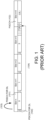
- Figure 1 illustrates a schematic diagram of channels for a DL transmission when used with analogue beamforming, where slot n, slot n+1 to slot n+4 are shown.
- the slot n represents a DL slot where the UE when decoding the PDCCH 100 receives DL data in PDSCH 101 and the UE reports feedback of the decoded result (ACK or NACK) in PUCCH 102.
- Reference numeral 103 indicates that the PDCCH contains a field representing where a PDSCH 101 data is received and in 104 the PDCCH contains a second field controlling when PUCCH 102 is transmitted to the base station.
- the numerals 0, 1, 2 and 3 in the slots n through n+3 represent DL slots and n+4 represents UL slots.
- the configuration and positioning of DL and UL slots is decided by the base station and need not be determined in advance. However, the position of the possible PDCCH occasions (at the start of slots n through n+3) are configured by the base station in advance. The UE need to continuously attempt to decode every possible PDCCH.
- any transport block sent over PDSCH there exists one bit representing the feedback-ACK or NACK which is included in the PUCCH (as indicated by the PDCCH).
- the base station attempts to decode the PUCCH, there are three possibilities which can include the following options a) PUCCH is correctly decoded and the feedback bit indicates ACK b) PUCCH is correctly decoded and the feedback bit indicates NACK, or c) the base station fails to decode the PUCCH.
- Option 'c' can occur due to interference or a weak UE signal at the time of the PUCCH, or alternatively because the UE did not send the PUCCH at all.
- Such a "missing PUCCH” may in turn occur because the UE failed to decode the original PDCCH, in which case the UE has not received the corresponding PDSCH.
- the purpose of the HARQ protocol is to recover from data decoding failures in both directions by sending feedback (ACK/NACK) from receiver to transmitting side allowing for retransmission.
- a new data indicator, NDI is provided.
- the NDI is toggled, from a previous value when new data is handled by the HARQ process.
- the toggling of the NDI refers to a scenario when previous received NDI for single HARQ process is either '0' and new NDI is decoded as '1' or vice versa.
- NDI When there is a HARQ retransmission, NDI is retained to its previous value.
- the NDI indicates the UE that the UE is prepared to receive a PDSCH transmission with new data for the single HARQ process ID, when the NDI is toggled. If the NDI is not toggled, then the UE is prepared to receive a PDSCH retransmission for the single HARQ process ID, which means that the base station sends the same data as in the preceding transmission(s) belonging to the HARQ process, to help the UE decode the data even if the UE has not succeeded in decoding those previous transmissions.
- the UE operates in a Continuous Mode Discontinuous Reception, C-DRX, which is a mode of UE configuration where the UE refrains from decoding the PDCCH as described above in Fig 1 .
- the purpose of the C-DRX mode is to allow the UE to reduce power consumption by creating a pattern of "sleep" periods when there is no application data to receive or transmit to and from the base station.
- the C-DRX configuration includes a C-DRX Inactivity timer, which is a timer running from 0 to a fixed time period. When the UE receives a PDCCH indicating a planned PDSCH or PUSCH containing new data, indicated by a toggled NDI, the C-DRX Inactivity timer is reset to 0.
- the UE If the C-DRX Inactivity timer ever runs out, i.e., if the maximum configured time interval is reached without the base station initiating any new data, then the UE enters an inactive state (i.e., the "sleep" period).
- each UE is connected to an evolved Node Base station, eNB, (in LTE) and a gNB simultaneously. Consequently, the UE can be configured to perform measurements necessary for the eNB connection in a regular pattern. Furthermore, during such a measurement occasion, the UE shall not be able to send or receive anything to/from the gNB. To the gNB, this appears as a measurement gap during which the UE is completely unreachable.
- eNB evolved Node Base station
- gNB evolved Node Base station
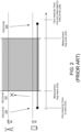
- the base station and the UE performs various steps for HARQ retransmission as described in Fig. 2 .
- the UE is configured with a C-DRX inactivity timer with a time interval set to 8ms and the measurement gap for the UE is set to 6ms.
- a new data transmission (indicated as #1) is initiated by the base station i.e., gNB, and PDCCH is signaled to the UE.
- This transmission consists of a MAC PDU which contains one or more RLC PDUs.
- the NDI for transmission #1 was set to "0".
- the gNB decodes 201 the corresponding PUCCH, the feedback for transmission #1 is NACK.
- the measurement gap starts 204.
- the gNB has to decide for a trade-off i.e., to a) complete ongoing transmissions early and 2) stop the UE from entering C-DRX inactive mode.
- Prior art document US 2009/0168731-A1 discloses a method for handling interactions between measurement gap, automated repeat request, discontinuous reception and discontinuous transmission in wireless communications concerning real-time data and non-real time data in both an uplink and a downlink.
- Various alternatives for handling HARQ/Measurement gap interactions are provided.
- Prior art document WO 2010/048998-A1 shows a method that in the event that a user device is unable to make or receive a retransmission at a first predetermined opportunity because of a measurement period, ensure that the user device is out of an energy-saving mode in order to monitor a control channel for control information for the retransmission at a further predetermined opportunity after the end of the measurement period.
- a method for handling downlink, DL, hybrid automatic repeat request, HARQ, transmissions for a user equipment, UE, operating in a connected discontinuous reception, C-DRX, mode is provided according to appended claim 1.
- a method for handling uplink, UL, hybrid automatic repeat request, HARQ, transmissions from a user equipment, UE operating in a connected discontinuous reception, C-DRX, mode is provided according to appended claim 6.
- a method for handling uplink, UL HARQ transmissions to a base station, performed by a UE operating in a C-DRX mode is provided according to appended claim 12.
- a base station for handling downlink, DL hybrid automatic repeat request, HARQ, transmissions for a user equipment, UE, operating in a connected discontinuous reception, C-DRX, mode, according to appended claim 17.
- a base station for handling uplink, UL hybrid automatic repeat request, HARQ, transmissions for a user equipment, UE, operating in a connected discontinuous reception, C-DRX, mode, according to appended claim 18.
- a user equipment, UE for handling uplink, UL, hybrid automatic repeat request, HARQ, transmissions, according to appended claim 19.
- An advantage of some embodiments is that alternative and/or improved approaches for handling downlink and uplink HARQ transmissions during C-DRX mode are provided.
- An advantage of some embodiments is that the proposed method allows toggling the value of the NDI to restart the C-DRX inactivity timer, since the usage the same value of the NDI shall not restart the C-DRX-inactivity timer, and there may be a chance of the timer elapsing before any other UL transmission takes place.
- the proposed method allows toggling the value of the NDI on DL and UL HARQ retransmissions when a measurement gap has occurred between the previous transmission attempt and a new transmission attempt from the base station and the UE.
- An advantage of some embodiments is that latency is reduced by toggling the value of the NDI to restart the C-DRX inactivity timer. It should be noted that, for real time critical applications, latency is vital. Thus, by toggling the value of NDI, the chances of entering the C-DRX inactive state, causing a long latency can be avoided. In some cases, retransmitting a MAC PDU which has already been received, costs far less in terms of latency for applications involving huge data traffic.
- An advantage of some embodiments is that the proposed method allows for configuration of a C-DRX inactivity timer to a lower value, i.e., for example, the C-DRX inactivity timer may be configured with a time interval of 10 milli-seconds, ms, since the chance of the UE entering into the undesirable state is mitigated.
- a shorter C-DRX inactivity timer generally leads to reduced power consumption by the UE.
- An advantage of some embodiments is that when the UE has an ongoing DL HARQ process but, due to a measurement gap, the C-DRX inactivity timer is about to expire.
- the base station i.e., gNB initiates a transmission on the same HARQ process ID, indicating to the UE that this transmission contains new data, while re-sending the same MAC PDU. This avoids losing the MAC PDU, while still preventing the UE from entering into the C-DRX inactive state.
- An advantage of some embodiments is that when the UE has an ongoing UL HARQ process but, due to a measurement gap, the C-DRX inactivity timer is about to expire.
- the base station i.e., gNB initiates a transmission on the same HARQ process ID, indicating to the UE that this transmission contains new data, in order to prevent the UE from entering into the C-DRX inactive state.
- An advantage of some embodiments is that when the UE is requested to start a new transmission on a previously used HARQ process ID shortly after a measurement gap as mentioned above, the UE shall re-send the same MAC PDU. This avoids losing the MAC PDU.
- base station and gNB are used interchangeably.
- the UE is connected to both eNB and gNB.
- the UE is configured with C-DRX on gNB.
- the UE is a New Radio, NR, capable UE, i.e., NR-UE.
- NR-UE New Radio
- the UE is configured to have LTE measurement gaps in its connection to gNB, and gNB is aware of the configured measurement gap such that gNB can take into account exactly when a measurement gap starts and ends.
- the new data indicator, NDI flag according to 3GPP TS 25.321 is used by a base station i.e., either Node B or eNodeB as an indication for the UE.
- a base station i.e., either Node B or eNodeB
- the conditions for operating the NDI are specified herein:
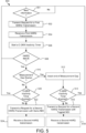
- FIG. 3 is a flowchart illustrating example method steps for handling downlink, DL HARQ transmission according to some embodiments.
- a base station i.e., a gNB implements various steps in method 300 for handling DL HARQ transmission as described herein.
- the method 300 comprises determining whether new information is available for DL transmission to a UE. If the base station determines that there is no new information available for DL transmission to the UE, then the base station continues to determine availability of new information for DL transmission to the UE.
- the method 300 comprises performing a first HARQ transmission related to a single HARQ process to the UE.
- the first HARQ transmission comprises information related to the single HARQ process with an associated new data indicator, NDI.
- the NDI is a binary value which can be either "0" or "1”.
- the NDI may be initialized to a value i.e., either "0" or "1" for performing the first HARQ transmission to the UE.
- the base station toggles the value of the NDI i.e., from either "0" to 1" or from "1" to "0” to indicate a change of information of the single HARQ process over a previous HARQ transmission.
- the base station initializes NDI to "0" for a first HARQ transmission
- the base station toggles the NDI to "1" for a second HARQ transmission to indicate to the UE that the second HARQ transmission includes new information.
- the toggling of the NDI indicates a change of information of the single HARQ process over the previous HARQ transmission.
- the method 300 comprises starting a C-DRX inactivity timer.
- the first HARQ transmission to the UE triggers an initiation or start of C-DRX inactivity timer at the UE and the base station.
- the C-DRX inactivity timer starts from a time interval "0" to a pre-configured timer interval i.e., 8 milli-seconds, ms.
- the time interval between the start and the expiry of the C-DRX inactivity timer is eight ms.
- the time interval between start and the expiry of the C-DRX inactivity timer may be less than ten ms.
- a difference between the time interval between the start and the expiry of the C-DRX inactivity timer and a time interval of the measurement gap is minimum.
- the method 300 comprises determining whether a HARQ NACK is received in PUCCH.
- the base station 50 determines whether a HARQ NACK is received in PUCCH for the first HARQ transmission from the UE. If the base station determines that there is no HARQ NACK received in PUCCH for the first HARQ transmission, then the base station determines that the first HARQ transmission to the UE is successful and the method 300 loops back to the step 301 for determining if there is any new information for DL transmission to the UE.
- the method 300 comprises detecting whether the measurement gap has started.
- the measurement gap is pre-configured to the UE by the base station and the configured measurement gap may be 6 ms. During the measurement gap period i.e., 6 ms, the UE is not reachable for the base station to perform for any data transmission and the UE performs measurement of neighbouring cells during the measurement gap period.
- the method 300 comprises awaiting an end of the measurement gap.
- the measurement gap ends after the time interval of 6ms.
- the method 300 comprises determining whether the C-DRX inactivity timer has expired at a time where the measurement gap has ended.
- the C-DRX inactivity timer expires only after the end of the measurement gap, as the configured time interval i.e., 8 ms, of the C-DRX inactivity timer is greater than the configured measurement gap i.e., 6 ms.
- the C-DRX inactivity timer is configured to expire in a pre-determined time interval after ending of the measurement gap.
- the C-DRX timer expires after the pre-determined time interval, which is 2 ms, in the above example. Therefore, it should be noted that the C-DRX inactivity timer is configured to expire in a shorter duration after ending of the measurement gap.
- the method 300 comprises performing a second HARQ transmission which is a retransmission of the information, with associated NDI to the UE for the single HARQ process.
- the second HARQ transmission is a retransmission of the information transmitted in the first HARQtransmission.
- value of the NDI is toggled in relation to a value of the NDI of the first HARQ transmission.
- the base station toggles the NDI for the second HARQ transmission though the second HARQ transmission is a retransmission of the information transmitted in the first HARQ transmission.
- step 312 If at step 312, it is determined that the C-DRX inactivity timer is expired after the ending of the measurement gap, then the method 300 loops back to the step 301 to determine the availability of new information for DL transmission to the UE.
- the method 300 comprises determining whether the C-DRX inactivity timer has expired. If the C-DRX timer has not expired, then at step 318, the method comprises performing a second HARQ transmission with same NDI.
- the second HARQ transmission is a retransmission of the information transmitted in the first HARQ transmission.
- the value of the NDI is not toggled for the second HARQ transmission.
- the base station 50 performs the second HARQ transmission with the same NDI for the second HARQ transmission.
- the method 300 loops back to the step 301 to determine the availability of new information for DL transmission to the UE.
- transmission #2 includes a second copy of the same MAC PDU.
- the RLC PDU contained inside the MAC PDU shall, according to the RLC protocol, be identified as duplicate and can be discarded.
- step 314 the incremental redundancy shall be reinitialized similar to that of new HARQ data transmissions.
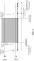
- Figure 4 is an example schematic diagram showing various steps between a base station 50 and a UE for DL HARQ transmission according to the flow chart described in Fig 3 .
- the base station 50 and the UE 30 performs various steps for DL HARQ retransmission as described herein.
- the UE 30 is configured with a C-DRX inactivity timer with a time interval of 8ms and the measurement gap for the UE is 6ms.
- a new data transmission (indicated as #1) is initiated by the base station i.e., gNB 50, and the PDCCH is signalled 302 to the UE 30.
- This transmission consists of a MAC PDU which contains one or more RLC PDUs.
- the NDI for transmission #1 was set to "0".
- the gNB 50 decodes the corresponding PUCCH 201, the feedback for transmission #1 is NACK 306.
- the measurement gap starts 308.
- the gNB 50 performs data transmission indicated as transmission #2 to the UE 30. Since transmission #1 was marked as NACK, the gNB 50 performs a HARQ transmission 314, indicated as transmission #2 to the UE 30.
- the gNB 50 performs a HARQ transmission, which is a retransmission of the same information transmitted in the transmission #1 with the toggled NDI, i.e., the value of the NDI is toggled to "1".
- the gNB 50 transmits the same data by a HARQ retransmission with toggled NDI to indicate the UE that the HARQ retransmission is new information so as to restart the C-DRX inactivity timer.
- the C-DRX Inactivity timer is reset 320.
- FIG. 5 is a flowchart illustrating example method steps for handling uplink, UL, HARQ transmission according to some embodiments.
- a base station i.e., gNB performs various steps in method 500 for handling UL HARQ transmission as described herein.
- the method comprises determining whether new information is available at the UE for UL transmission to the base station. If the base station determines that there is no new information available for UL transmission, then the base station continues to determining if there is any new information for UL transmission from the UE.
- the method comprises transmitting a request for a first HARQ transmission related to a single HARQ process with an associated NDI to the UE.
- the base station toggles the value of the NDI to indicate a change of information of the single HARQ process over a previous HARQ transmission.
- the method 500 comprises receiving a first HARQ transmission from the UE.
- the method 500 Upon reception of the first HARQ transmission, at step 506, the method 500 comprises starting a C-DRX inactivity timer.
- the first HARQ transmission to the UE triggers an initiation or start of C-DRX inactivity timer at the UE and the base station.
- the C-DRX inactivity timer starts from a time interval "0"ms to a pre-configured timer interval i.e., 8 ms.
- the method 500 comprises determining whether a HARQ NACK is received in PUCCH. If the base station 50 determines that there is no HARQ NACK received in PUCCH for the first HARQ transmission, then the base station determines that the first HARQ transmission to the UE is successful and the method 500 loops back to the step 501 for determining if there is any new information for UL transmission from the UE.
- the method 500 comprises detecting whether the measurement gap has started. When it is detected that the measurement gap has started, then at step 512, the method 500 comprises awaiting end of the measurement gap. The measurement gap ends after the time interval of 6ms. After the end of the measurement gap, at step 514, the method 500 comprises determining whether the C-DRX inactivity timer has expired at a time where the measurement gap has ended.
- the method 500 comprises transmitting a request for second HARQ transmission with toggled NDI.
- the request for second HARQ transmission is a request for retransmission of the information transmitted in the first HARQ transmission.
- the UE When the UE receives the request for second HARQ transmission with toggled NDI, the UE transmits the second HARQ transmission which is a retransmission of information of the first HARQ transmission as in step 504.
- the method 500 comprises receiving the second HARQ transmission.
- the base station receives a retransmission of the same information during the second HARQ transmission even though the NDI is toggled, to allow the UE to perform a new transmission.
- step 514 If at step 514, it is determined that the C-DRX inactivity timer is expired after the ending of the measurement gap, then the method 500 loops back to the step 501 to determine the availability of new information for UL transmission from the UE.
- the method 500 comprises determining whether the C-DRX inactivity timer has expired. If the C-DRX timer has not expired, then at step 522, the method comprises transmitting a request for a second HARQ transmission with same NDI. The request for the second HARQ transmission is for retransmission of the information transmitted in the first HARQ transmission.
- the method 500 comprises receiving a second HARQ transmission.
- the second HARQ transmission is a retransmission of information of the first HARQ transmission.
- step 520 if it is determined that the C-DRX inactivity timer has expired, then the method 500 loops back to the step 501 to determine the availability of new information for UL transmission from the UE.
- the base station performs the second HARQ transmission, which is a retransmission of same information, thereby increasing the risk that the UE transmits a MAC SDU which has already been successfully received by the gNB and has been delivered to higher layers.
- transmission #1 (302) was successful and decoded correctly by the gNB, so that the toggled NDI for transmission #2 (306) actually indicates a request for new data.
- transmission #2 will include a second copy of the same MAC PDU.
- the RLC PDU contained inside the MAC PDU shall, according to the RLC protocol, be identified as duplicate and discarded.
- Figure 6 is an example schematic diagram showing various steps between a base station 50 and a UE 30 for UL HARQ transmission according to the flow chart described in Fig 5 .
- the base station 50 and the UE 30 performs various steps for UL HARQ retransmission as described herein.
- the base station i.e., gNB 50 initiates a transmission of a request (indicated as #1) for the first HARQ transmission and the PDCCH is signalled 502 to the UE 30.
- the request for the first transmission is related to a single HARQ process and the request is transmitted along with an NDI.
- the value of the NDI is set to "0".
- the UE transmits the first UL HARQ transmission to the gNB 50.
- the gNB 50 receives the first UL HARQ transmission from the UE 30.
- the gNB 50 decodes 508 the corresponding PUCCH 201, the feedback for transmission #1 is NACK.
- the measurement gap has started 510.
- the gNB 50 transmits a request for a second HARQ transmission, indicated as transmission #2 to the UE 30. Since, the transmission #1 was marked as NACK, the gNB 50 transmits 516 a request for second HARQ transmission, indicated as transmission #2 to the UE 30.
- the gNB 50 transmits the request for second HARQ transmission, which is a request for retransmission of the same information transmitted by the UE 30 in the transmission #1.
- the request for the second HARQ transmission is transmitted with the toggled NDI to indicate the UE 30 that the request for the second HARQ transmission is for new information, although the request for the second HARQ transmission is for retransmission of same information transmitted by the UE in the transmission #1.
- the C-DRX Inactivity timer is reset 522.
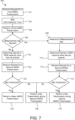
- FIG. 7 is a flowchart illustrating example method steps for handling uplink, UL HARQ transmission according to some embodiments.
- the UE performs various steps in method 700 for handling UL HARQ retransmission as described herein.
- the UE receives a request for first HARQ transmission from a base station.
- the method 700 comprises starting a C-DRX inactivity timer.
- the C-DRX inactivity timer is running
- the UE performs the first UL HARQ transmission to the base station.
- the method 700 comprises detecting whether the measurement gap has started.
- the method 700 comprises awaiting end of the measurement gap. After the end of the measurement gap, at step 710, determining that the C-DRX inactivity timer has not expired at a time where the measurement gap has ended. When it is determined that the C-DRX inactivity timer has not expired, at step 712, the method comprises receiving a request for second HARQ transmission from the base station. At step 714, the method 700 comprises determining whether the NDI is toggled in the received request from the base station. If it is determined that the NDI is toggled, then at step 716, the method comprises performing a second HARQ transmission to the base station 50.
- the UE during the second HARQ transmission, transmits the same information which it has transmitted to the base station in the first HARQ transmission at step 704.
- the UE at step 716, performs the second HARQ transmission which is a retransmission of the same information that the UE has transmitted to the base station in step 704 even though the NDI is toggled, to allow the UE to perform a new transmission. Therefore, it should be noted that the UE performs retransmission of the same information during the second HARQ transmission to the base station, at step 716.
- the C-DRX inactivity timer is restarted.
- the method 700 comprises performing a retransmission of the same information during the second HARQ transmission.
- the UE transmits the same information which it has transmitted to the base station in the first HARQ transmission at step 704. Therefore, it should be noted that the UE performs the retransmission of the same information when the NDI is not toggled (i.e., NDI is same in relation to the value of the NDI of the first HARQ transmission).
- the method 700 comprises determining that the C-DRX inactivity timer has not expired.
- the method 700 comprises receiving a request for second HARQ transmission.
- the method comprises determining whether the whether the NDI is toggled in the received request from the base station 50. If it is determined that the NDI is toggled, then at step 724, the method comprises performing a new HARQ transmission to the base station. The UE transmits new information to the base station during the new HARQ transmission at step 724, when the NDI is toggled.
- the toggled NDI indicates the UE for a new information transmission and then the UE transmits new information to the base station.
- the C-DRX inactivity timer is restarted.
- the method 700 comprises performing a retransmission of the same information during the second HARQ transmission.
- the UE transmits the same information which it has transmitted to the base station in the first HARQ transmission at step 704. Therefore, it should be noted that the UE performs the retransmission of the same information when the NDI is not toggled (i.e., NDI is same in relation to the value of the NDI of the first HARQ transmission) during the second HARQ transmission.
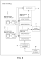
- FIG. 8 is a block diagram of a base station showing functional modules for handling DL and UL HARQ transmissions according to the flow charts described in Figs. 3 and 5 .
- the base station 50 comprises a scheduler, 52, a plurality of input buffers, 53, 54, storing segments of data streams pertaining to individual UEs, i.e., for example, UEs 30a-30n.
- a HARQ entity 55, 56 each comprising a number of HARQ processes for handling simultaneous transmissions to several UEs, that is, for each UE.
- the base station 50 also comprises Layer 1 processing means 57 for transferring data from respective HARQ processes.
- the base station 50 moreover comprises a UE feedback decoder 59 and a Layer 1 receiver 60.
- Each HARQ process 55, 56, in a given UE is mirrored in the base station 50 and corresponds to a given data stream which is received by a particular UE.
- more data streams may be used by the UE simultaneously corresponding to one application or more simultaneous applications running on the UE, possibly with different QoS requirements.
- consecutive data may be transmitted for the same UE, the consecutive transmission belonging to different HARQ processes.
- the base station 50 comprises one or more input buffer queues dedicated to a corresponding set of HARQ processes.
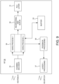
- FIG. 9 is a block diagram of a UE 30 showing functional modules for handling UL HARQ transmissions according to the flow chart described in Fig. 7 .
- the UE 30 includes a HS-SCCH decoding means, i.e., a channel decoder 33, for decoding the downlink HD-PDSCH channel, arrangements comprising a number of HARQ processes 36 namely HARQ process 1 to HARQ process J, a reordering and queue 39, and a Radio Link Control layer, RLC means, 31.
- the UE 30 is provided with a feedback processing means, 38, and layer 1 processing, 37, for providing feedback on the HS-DPCCH channel.
- buffer means 35 are provided for each HARQ process 36.
- the buffer means 35 may be arranged as one resource or buffer means 35 may be a plurality of resources or buffers.
- the buffer means 35 may be arranged as a soft memory which is partitioned across the HARQ processes in a semi- static fashion through upper layer signalling.
- the reordering and queue, 39 routes the MAC-hs PDU's to the correct reordering buffer based on a Queue ID.
- the reordering and queue reorders received MAC-hs PDU's according to the received transmit sequence number, TSN.
- TSN transmit sequence number
- the RLC layer 31 in 3GPP can operate in three modes, transparent mode, unacknowledged mode and acknowledged mode, AM, which are described herein.
- AM mode incorrectly received Protocol Data Units, PDU's discovered by the receiving side are effected to be retransmitted by the transmitting side by means of an Automatic Repeat Request, ARQ, protocol.
- An AM RLC entity consists of a transmitting side, and a receiving side, where the transmitting side of the AM RLC entity transmits RLC PDU's and the receiving side of the AM RLC entity receives RLC PDU's.
- An AM RLC entity resides in the UE and in the radio network control, RNC respectively.
- the transmitting side segments and/or concatenates RLC service data units, SDU's into PDU's of a fixed length.
- the receiving side reassembles received PDU's into RLC SDU's and transmits these to higher data layers.
- SDU's are received from the layer above the RLC layer.
- the RLC layer is responsible for the delivery of SDU's in consecutive order.
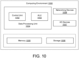
- Figure 10 illustrates an example computing environment 1000 implementing a method, a base station and a user equipment for handling DL and UL HARQ transmissions as described in Figs. 3 , 5 and 7 .
- the computing environment 1000 comprises at least one data processing unit 1004 that is equipped with a control unit 1002 and an Arithmetic Logic Unit, ALU 1003, a memory 1005, a storage 1006, plurality of networking devices 1008 and a plurality Input output, I/O devices 1007.
- the data processing unit 1004 is responsible for processing the instructions of the algorithm.
- the data processing unit 1004 is capable of executing software instructions stored in memory 1005.
- the data processing unit 1004 receives commands from the control unit 1002 in order to perform its processing. Further, any logical and arithmetic operations involved in the execution of the instructions are computed with the help of the ALU 1003.
- the overall computing environment 1000 can be composed of multiple homogeneous and/or heterogeneous cores, multiple CPUs of different kinds, special media and other accelerators.
- the data processing unit 1004 is responsible for processing the instructions of the algorithm. Further, the plurality of data processing units 1004 may be located on a single chip or over multiple chips.
- the algorithm comprising of instructions and codes required for the implementation are stored in either the memory 1005 or the storage 1006 or both. At the time of execution, the instructions may be fetched from the corresponding memory 1005 and/or storage 1006 and executed by the data processing unit 1004.
- networking devices 1008 or external I/O devices 1007 may be connected to the computing environment to support the implementation through the networking devices 1008 and the I/O devices 1007.
- the embodiments disclosed herein can be implemented through at least one software program running on at least one hardware device and performing network management functions to control the elements.
- the elements shown in Figure 10 include blocks which can be at least one of a hardware device, or a combination of hardware device and software module.
- a communication system includes telecommunication network 1110, such as a 3GPP-type cellular network, which comprises access network 1111, such as a radio access network, and core network 1114.
- Access network 1111 comprises a plurality of base stations 1112a, 1112b, 1112c, such as NBs, eNBs, gNBs or other types of wireless access points, each defining a corresponding coverage area 1113a, 1113b, 1113c.
- Each base station 1112a, 1112b, 112c is connectable to core network 1114 over a wired or wireless connection 1115.
- a first UE 1191 located in coverage area 1113c is configured to wirelessly connect to, or be paged by, the corresponding base station 1112c.
- a second UE 1192 in coverage area 1113a is wirelessly connectable to the corresponding base station 1112a. While a plurality of UEs 1191, 1192 are illustrated in this example, the disclosed embodiments are equally applicable to a situation where a sole UE is in the coverage area or where a sole UE is connecting to the corresponding base station 1112.
- Telecommunication network 1110 is itself connected to host computer 1130, which may be embodied in the hardware and/or software of a standalone server, a cloud-implemented server, a distributed server or as processing resources in a server farm.
- Host computer 1130 may be under the ownership or control of a service provider or may be operated by the service provider or on behalf of the service provider.
- Connections 1121 and 1122 between telecommunication network 1110 and host computer 1130 may extend directly from core network 814 to host computer 1130 or may go via an optional intermediate network 1120.
- Intermediate network 1120 may be one of, or a combination of more than one of, a public, private or hosted network; intermediate network 1120, if any, may be a backbone network or the Internet; in particular, intermediate network 1120 may comprise two or more sub-networks (not shown).
- the communication system of Figure 11 as a whole enables connectivity between the connected UEs 1191, 1192 and host computer 1130.
- the connectivity may be described as an over-the-top (OTT) connection 1150.
- Host computer 1130 and the connected UEs 1191, 1192 are configured to communicate data and/or signalling via OTT connection 1150, using access network 1111, core network 1114, any intermediate network 1120 and possible further infrastructure (not shown) as intermediaries.
- OTT connection 1150 may be transparent in the sense that the participating communication devices through which OTT connection 1150 passes are unaware of routing of uplink and downlink communications.
- base station 1112 may not or need not be informed about the past routing of an incoming downlink communication with data originating from host computer 1130 to be forwarded (e.g., handed over) to a connected UE 1191. Similarly, base station 1112 need not be aware of the future routing of an outgoing uplink communication originating from the UE 1191 towards the host computer 1130.
- host computer 1210 comprises hardware 1215 including communication interface 1216 configured to set up and maintain a wired or wireless connection with an interface of a different communication device of communication system 1200.
- Host computer 1210 further comprises processing circuitry 1218, which may have storage and/or processing capabilities.
- processing circuitry 1218 may comprise one or more programmable processors, application-specific integrated circuits, field programmable gate arrays or combinations of these (not shown) adapted to execute instructions.
- Host computer 1210 further comprises software 1211, which is stored in or accessible by host computer 1210 and executable by processing circuitry 1218.
- Software 1211 includes host application 1212.
- Host application 912 may be operable to provide a service to a remote user, such as UE 1230 connecting via OTT connection 1250 terminating at UE 1230 and host computer 1210. In providing the service to the remote user, host application 1212 may provide user data which is transmitted using OTT connection 950.
- Communication system 1200 further includes base station 1220 provided in a telecommunication system and comprising hardware 1225 enabling it to communicate with host computer 1210 and with UE 1230.
- Hardware 1225 may include communication interface 1226 for setting up and maintaining a wired or wireless connection with an interface of a different communication device of communication system 1200, as well as radio interface 1227 for setting up and maintaining at least wireless connection 1270 with UE 1230 located in a coverage area (not shown in Figure 12 ) served by base station 1220.
- Communication interface 1226 may be configured to facilitate connection 1260 to host computer 1210. Connection 1260 may be direct or it may pass through a core network (not shown in Figure 12 ) of the telecommunication system and/or through one or more intermediate networks outside the telecommunication system.
- hardware 1225 of base station 1220 further includes processing circuitry 1228, which may comprise one or more programmable processors, application-specific integrated circuits, field programmable gate arrays or combinations of these (not shown) adapted to execute instructions.
- processing circuitry 1228 may comprise one or more programmable processors, application-specific integrated circuits, field programmable gate arrays or combinations of these (not shown) adapted to execute instructions.
- Base station 1220 further has software 1221 stored internally or accessible via an external connection.
- Communication system 1200 further includes UE 1230 already referred to. It's hardware 1235 may include radio interface 1237 configured to set up and maintain wireless connection 1270 with a base station serving a coverage area in which UE 1230 is currently located. Hardware 1235 of UE 1230 further includes processing circuitry 1238, which may comprise one or more programmable processors, application-specific integrated circuits, field programmable gate arrays or combinations of these (not shown) adapted to execute instructions.
- the UE 1230 further comprises software 1231, which is stored in or accessible by UE 1230 and executable by processing circuitry 1238.
- Software 1231 includes client application 1232. Client application 1232 may be operable to provide a service to a human or non-human user via UE 1230, with the support of host computer 910.
- an executing host application 1212 may communicate with the executing client application 1232 via OTT connection 1250 terminating at UE 1230 and host computer 1210.
- client application 1232 may receive request data from host application 1212 and provide user data in response to the request data.
- OTT connection 1250 may transfer both the request data and the user data.
- Client application 1232 may interact with the user to generate the user data that it provides.
- host computer 1210, base station 1220 and UE 1230 illustrated in Figure 9 may be similar or identical to host computer 1130, one of base stations 112a, 1112b, 1112c and one of UEs 1191, 1192 of Figure 11 , respectively.
- the inner workings of these entities may be as shown in Figure 12 and independently, the surrounding network topology may be that of Figure 11 .
- OTT connection 1250 has been drawn abstractly to illustrate the communication between host computer 1210 and UE 1230 via base station 1220, without explicit reference to any intermediary devices and the precise routing of messages via these devices.
- Network infrastructure may determine the routing, which it may be configured to hide from UE 1230 or from the service provider operating host computer 1210, or both. While OTT connection 1250 is active, the network infrastructure may further take decisions by which it dynamically changes the routing (e.g., on the basis of load balancing consideration or reconfiguration of the network).
- Wireless connection 1270 between UE 1230 and base station 1220 is in accordance with the teachings of the embodiments described throughout this disclosure.
- One or more of the various embodiments improve the performance of OTT services provided to UE 1230 using OTT connection 1250.
- Various embodiments described in the present disclosure can be used for reducing latency during delivery of Over-the-Top, OTT, services from the network to the UEs.
- OTT Over-the-Top
- the OTT content can be delivered to the UEs by reducing the latency of the content being delivered from the base station to the UE.
- DTX Discontinuous Transmission meaning a device does not transmit anything, here used to represent an expected message which appears to be missing completely DRX Discontinuous Reception, meaning a device does not receive any transmissions C-DRX Connected Mode DRX, a configuration where the UE can go into a DRX state at certain times Meas gap Measurement gap, meaning a period during which UE suspends communication in order to perform measurements ACK Acknowledged, indicating a message was received and decoded successfully NACK Not Acknowledged, indicating a message was not received or not decoded PDCCH Physical Downlink Control Channel PUCCH Physical Uplink Control Channel PDSCH Physical Downlink Shared Channel PUSCH Physical Uplink Shared Channel DL Downlink, anything sent from the RBS to the UE UL Uplink, anything sent from the UE to the RBS DCI Downlink Control Information, an information block transmitted over PDCCH NDI New Data Indicator, a field contained in the DCI HARQ Hybrid Automat
Landscapes
- Engineering & Computer Science (AREA)
- Computer Networks & Wireless Communication (AREA)
- Signal Processing (AREA)
- Mobile Radio Communication Systems (AREA)
Claims (19)
- Verfahren (300), das von einer Basisstation (50) durchgeführt wird, zur Handhabung von Downlink-Übertragungen, DL-Übertragungen, hybrider automatischer Wiederholungsanforderungen, HARQ, für eine Benutzereinrichtung, UE, (30) die in einem Modus verbundenen diskontinuierlichen Empfangs, C-DRX, funktioniert, wobei das Verfahren (300) umfasst:Durchführen (302) einer ersten HARQ-Übertragung, die Informationen in Bezug auf einen einzelnen HARQ-Prozess umfasst, an die UE (30) mit einem zugehörigen Indikator neuer Daten, NDI, wobei ein Wechseln des NDI zumindest eine Änderung von Informationen des einzelnen HARQ-Prozesses gegenüber einer vorherigen HARQ-Übertragung anzeigt, wobei die erste HARQ-Übertragung außerdem einen C-DRX-Inaktivitätszeitgeber startet (304);Bestimmen, dass eine HARQ-Negativbestätigung, NACK, für die gesendeten Informationen von der UE (30) empfangen wurde (306);Erkennen, ob eine Messlücke begonnen hat (308), und, wenn die Messlücke begonnen hat, Warten (310) auf ein Ende der Messlücke;Bestimmen, ob der C-DRX-Inaktivitätszeitgeber zu einem Zeitpunkt abgelaufen ist (312), zu dem die Messlücke geendet hat; und,wenn der C-DRX-Inaktivitätszeitgeber nicht abgelaufen ist, Durchführen (314) einer zweiten HARQ-Übertragung, die eine Neuübertragung der Informationen ist, mit dem zugehörigen NDI an die UE (30) für den einzelnen HARQ-Prozess, wobei ein Wert des NDI in Bezug auf einen Wert des NDI der ersten HARQ-Übertragung gewechselt wird.
- Verfahren (300) nach Anspruch 1, wobei das Verfahren (300), wenn die Messlücke nicht begonnen hat (308) und wenn der C-DRX-Inaktivitätszeitgeber nicht abgelaufen ist (316), ein Durchführen (318) einer zweiten HARQ-Übertragung, die eine Neuübertragung der Informationen ist, mit dem zugehörigen NDI an die UE (30) für den einzelnen HARQ-Prozess umfasst, wobei der NDI-Wert in Bezug auf den NDI-Wert der ersten HARQ-Übertragung gleich ist.
- Verfahren (300) nach einem der vorhergehenden Ansprüche, wobei der C-DRX-Inaktivitätszeitgeber durch die zweite HARQ-Übertragung neu gestartet wird (320).
- Verfahren (300) nach einem der vorhergehenden Ansprüche, wobei die Messlücke sich zumindest teilweise mit einem Zeitintervall zwischen einem Start und einem Ablauf des C-DRX-Inaktivitätszeitgebers überlappt.
- Verfahren (300) nach einem der vorhergehenden Ansprüche, wobei der C-DRX-Inaktivitätszeitgeber so konfiguriert ist, dass er in einem vorgegebenen Zeitintervall nach dem Enden (310) der Messlücke abläuft.
- Verfahren (500), das von einer Basisstation (50) durchgeführt wird, zur Handhabung von Uplink-Übertragungen, UL-Übertragungen, hybrider automatischer Wiederholungsanforderungen, HARQ, von einer Benutzereinrichtung, UE, (30) die in einem Modus verbundenen diskontinuierlichen Empfangs, C-DRX, funktioniert, wobei das Verfahren (500) umfasst:Senden (502) einer Anforderung für eine erste HARQ-Übertragung in Bezug auf einen einzelnen HARQ-Prozess mit einem zugehörigen Indikator neuer Daten, NDI, an die UE (30), wobei ein Wechseln des NDI zumindest eine Änderung von Informationen des einzelnen HARQ-Prozesses gegenüber einer vorherigen Übertragung anzeigt, wobei die erste HARQ-Übertragung (504) von der UE außerdem einen C-DRX-Inaktivitätszeitgeber startet (506);Empfangen der ersten HARQ-Übertragung (504) von der UE (30) und Bestimmen, dass eine HARQ-Negativbestätigung, NACK, empfangen wurde (508);Erkennen, ob eine Messlücke begonnen hat (510), und, wenn die Messlücke begonnen hat, Warten (512) auf ein Ende der Messlücke;Bestimmen, ob der C-DRX-Inaktivitätszeitgeber zu einem Zeitpunkt abgelaufen ist (514), zu dem die Messlücke geendet hat; und,wenn der C-DRX-Inaktivitätszeitgeber nicht abgelaufen ist (514), Senden (516) einer Anforderung für eine zweite HARQ-Übertragung der Informationen mit dem zugehörigen NDI an die UE (30) für den einzelnen HARQ-Prozess, wobei ein Wert des NDI in Bezug auf einen Wert des NDI der ersten HARQ-Übertragung gewechselt wird.
- Verfahren (500) nach Anspruch 6, wobei das Verfahren (500), wenn die Messlücke nicht begonnen hat (510) und wenn der C-DRX-Inaktivitätszeitgeber nicht abgelaufen ist (520), umfasst:Senden (522) einer Anforderung für eine zweite HARQ-Übertragung mit dem zugehörigen NDI an die UE (30) für den einzelnen HARQ-Prozess, wobei ein Wert des NDI in Bezug auf einen Wert des NDI der ersten HARQ-Übertragung gleich ist.
- Verfahren (500) nach einem der Ansprüche 6 oder 7, wobei das Verfahren ferner umfasst:
Empfangen (518, 524) der zweiten HARQ-Übertragung von der UE (30). - Verfahren (500) nach einem der vorhergehenden Ansprüche 6 bis 8, wobei der C-DRX-Inaktivitätszeitgeber durch den Empfang (518, 524) der zweiten HARQ-Übertragung neu gestartet wird.
- Verfahren (500) nach einem der vorhergehenden Ansprüche 6 bis 9, wobei die Messlücke sich zumindest teilweise mit einem Zeitintervall zwischen einem Start und einem Ablauf des C-DRX-Inaktivitätszeitgebers überlappt.
- Verfahren (500) nach einem der vorhergehenden Ansprüche 6 bis 10, wobei der C-DRX-Inaktivitätszeitgeber so konfiguriert ist, dass er in einem vorgegebenen Zeitintervall nach dem Enden (512) der Messlücke abläuft.
- Verfahren (700), das von einer Benutzereinrichtung, UE, (30) durchgeführt wird, zur Handhabung von Uplink-Übertragungen, UL-Übertragungen, hybrider automatischer Wiederholungsanforderungen, HARQ, an eine Basisstation (50), wobei die UE (30) in einem Modus verbundenen diskontinuierlichen Empfangs, C-DRX, funktioniert, wobei das Verfahren (700) umfasst:Empfangen (701) einer Anforderung für eine erste HARQ-Übertragung in Bezug auf einen einzelnen HARQ-Prozess mit einem zugehörigen Indikator neuer Daten, NDI, von der Basisstation (50), wobei ein Wechseln des NDI zumindest eine Änderung von Informationen des einzelnen HARQ-Prozesses gegenüber einer vorherigen Übertragung anzeigt, wobei die Anforderung für die erste HARQ-Übertragung außerdem einen C-DRX-Inaktivitätszeitgeber startet (702);Durchführen (704) der ersten HARQ-Übertragung an die Basisstation (50) und Erkennen, ob eine Messlücke begonnen hat (706), und, wenn die Messlücke begonnen hat, Warten auf ein Ende (708) der Messlücke;Bestimmen, dass der C-DRX-Inaktivitätszeitgeber zu einem Zeitpunkt, zu dem die Messlücke geendet hat, nicht abgelaufen ist (710);wenn der C-DRX-Inaktivitätszeitgeber nicht abgelaufen ist, Empfangen (712) einer Anforderung für eine zweite HARQ-Übertragung der Informationen mit dem zugehörigen NDI von der Basisstation (50) für den einzelnen HARQ-Prozess;Bestimmen (714), ob ein Wert des NDI in Bezug auf einen Wert des NDI der ersten HARQ-Übertragung gewechselt wird; und,wenn der Wert des NDI gewechselt wird, Durchführen (716) einer Neuübertragung der Informationen während der zweiten HARQ-Übertragung an die Basisstation (50).
- Verfahren nach Anspruch 12, wobei, wenn der Wert des NDI nicht gewechselt wird, eine Neuübertragung während der zweiten HARQ-Übertragung durchgeführt wird (726).
- Verfahren nach einem der Ansprüche 12 oder 13, wobei das Verfahren (700), wenn die Messlücke nicht begonnen hat (706) und wenn der C-DRX-Inaktivitätszeitgeber nicht abgelaufen ist (718), umfasst:Empfangen (720) einer Anforderung für eine zweite HARQ-Übertragung mit einem zugehörigen NDI von der Basisstation (50) für den einzelnen HARQ-Prozess;Bestimmen (722), ob ein Wert des NDI in Bezug auf einen Wert des NDI der ersten HARQ-Übertragung gewechselt wird;wenn der Wert des NDI gewechselt wird, Durchführen (724) einer neuen HARQ-Übertragung an die UE (30); undwenn der Wert des NDI nicht gewechselt wird, Durchführen (726) einer Neuübertragung während der zweiten HARQ-Übertragung an die UE (30).
- Verfahren (700) nach einem der vorhergehenden Ansprüche 12 bis 14, wobei der C-DRX-Inaktivitätszeitgeber durch die zweite HARQ-Neuübertragung neu gestartet wird.
- Verfahren (700) nach einem der vorhergehenden Ansprüche 12 bis 15, wobei die Messlücke sich zumindest teilweise mit einem Zeitintervall zwischen einem Start und einem Ablauf des C-DRX-Inaktivitätszeitgebers überlappt.
- Basisstation (50) zum Handhaben von Downlink-Übertragungen, DL-Übertragungen, hybrider automatischer Wiederholungsanforderungen, HARQ, für eine Benutzereinrichtung, UE, (30) die in einem Modus verbundenen diskontinuierlichen Empfangs, C-DRX, funktioniert, wobei die Basisstation (50) eine Mehrzahl von HARQ-Entitäten (55, 56) aufweist, die mit einem Scheduler (52) zusammenarbeitet, um Rahmen von der Basisstation (50) an die UE (30) zu senden, wobei die Basisstation (50) ausgelegt ist zum:Durchführen (302) einer ersten HARQ-Übertragung, die Informationen in Bezug auf einen einzelnen HARQ-Prozess umfasst, an die UE (30) mit einem zugehörigen Indikator neuer Daten, NDI, wobei ein Wechseln des NDI zumindest eine Änderung von Informationen des einzelnen HARQ-Prozesses gegenüber einer vorherigen HARQ-Übertragung anzeigt, wobei die erste HARQ-Übertragung außerdem einen C-DRX-Inaktivitätszeitgeber startet (304);Bestimmen, dass eine HARQ-Negativbestätigung, NACK, für die gesendeten Informationen von der UE (30) empfangen wurde (306);Erkennen, ob eine Messlücke begonnen hat (308), und, wenn die Messlücke begonnen hat, Warten (310) auf ein Ende (310) der Messlücke;Bestimmen, ob der C-DRX-Inaktivitätszeitgeber zu einem Zeitpunkt abgelaufen ist (312), zu dem die Messlücke geendet hat; und,wenn der C-DRX-Inaktivitätszeitgeber nicht abgelaufen ist, Durchführen (314) einer zweiten HARQ-Übertragung, die eine Neuübertragung der Informationen ist, mit dem zugehörigen NDI an die UE (30) für den einzelnen HARQ-Prozess, wobei ein Wert des NDI in Bezug auf einen Wert des NDI der ersten HARQ-Übertragung gewechselt wird.
- Basisstation (50) zum Handhaben von Uplink-Übertragungen, UL-Übertragungen, hybrider automatischer Wiederholungsanforderungen, HARQ, von einer Benutzereinrichtung, UE, (30) die in einem Modus verbundenen diskontinuierlichen Empfangs, C-DRX, funktioniert, wobei die Basisstation (50) eine Mehrzahl von HARQ-Entitäten (55, 56) aufweist, die mit einem Scheduler (52) zusammenarbeitet, um Rahmen von der Basisstation (50) an die UE (30) zu senden, wobei die Basisstation (50) ausgelegt ist zum:Senden (502) einer Anforderung für eine erste HARQ-Übertragung in Bezug auf einen einzelnen HARQ-Prozess mit einem zugehörigen Indikator neuer Daten, NDI, an die UE (30), wobei ein Wechseln des NDI zumindest eine Änderung von Informationen des einzelnen HARQ-Prozesses gegenüber einer vorherigen Übertragung anzeigt, wobei die Anforderung für die erste HARQ-Übertragung (504) von der UE außerdem einen C-DRX-Inaktivitätszeitgeber startet (506);Empfangen der ersten HARQ-Übertragung (504) von der UE (30) und Bestimmen, dass eine HARQ-Negativbestätigung, NACK, empfangen wurde (508);Erkennen, ob eine Messlücke begonnen hat (510), und, wenn die Messlücke begonnen hat, Warten (512) auf ein Ende (512) der Messlücke; undBestimmen, ob der C-DRX-Inaktivitätszeitgeber zu einem Zeitpunkt abgelaufen ist (514), zu dem die Messlücke geendet hat;wenn der C-DRX-Inaktivitätszeitgeber nicht abgelaufen ist (514), Senden (516) einer Anforderung für eine zweite HARQ-Übertragung der Informationen mit dem zugehörigen NDI an die UE (30) für den einzelnen HARQ-Prozess, wobei ein Wert des NDI in Bezug auf einen Wert des NDI der ersten HARQ-Übertragung gewechselt wird.
- UE (30) zum Handhaben von Uplink-Übertragungen, UL-Übertragungen, hybrider automatischer Wiederholungsanforderungen, HARQ, an eine Basisstation, wobei die UE (30) in einem Modus verbundenen diskontinuierlichen Empfangs, C-DRX, funktioniert, wobei die UE (30) an mindestens einem HARQ-Prozess (36) zum Senden von Daten an eine Basisstation (50) beteiligt ist, wobei die UE (30) ausgelegt ist zum:Empfangen (701) einer Anforderung für eine erste HARQ-Übertragung in Bezug auf einen einzelnen HARQ-Prozess mit einem zugehörigen Indikator neuer Daten, NDI, von der Basisstation (50), wobei ein Wechseln des NDI zumindest eine Änderung von Informationen des einzelnen HARQ-Prozesses gegenüber einer vorherigen Übertragung anzeigt, wobei die Anforderung für die erste HARQ-Übertragung außerdem einen C-DRX-Inaktivitätszeitgeber startet (702);Durchführen (704) der ersten HARQ-Übertragung an die Basisstation (50) und Erkennen, ob eine Messlücke begonnen hat (706), und, wenn die Messlücke begonnen hat, Warten auf ein Ende (708) der Messlücke;Bestimmen, dass der C-DRX-Inaktivitätszeitgeber zu einem Zeitpunkt, zu dem die Messlücke geendet hat, nicht abgelaufen ist (710);wenn der C-DRX-Inaktivitätszeitgeber nicht abgelaufen ist, Empfangen (712) einer Anforderung für eine zweite HARQ-Übertragung der Informationen mit dem zugehörigen NDI von der Basisstation (50) für den einzelnen HARQ-Prozess;Bestimmen (714), ob ein Wert des NDI in Bezug auf einen Wert des NDI der ersten HARQ-Übertragung gewechselt wird; und,wenn der Wert des NDI gewechselt wird, Durchführen (716) einer Neuübertragung der Informationen während der zweiten HARQ-Übertragung an die Basisstation (50).
Applications Claiming Priority (1)
| Application Number | Priority Date | Filing Date | Title |
|---|---|---|---|
| PCT/EP2021/051344 WO2022156896A1 (en) | 2021-01-21 | 2021-01-21 | New data indicator handling for harq transmissions during c-drx mode |
Publications (2)
| Publication Number | Publication Date |
|---|---|
| EP4282102A1 EP4282102A1 (de) | 2023-11-29 |
| EP4282102B1 true EP4282102B1 (de) | 2024-10-30 |
Family
ID=74236185
Family Applications (1)
| Application Number | Title | Priority Date | Filing Date |
|---|---|---|---|
| EP21701733.4A Active EP4282102B1 (de) | 2021-01-21 | 2021-01-21 | Neue datenindikatorhandhabung für harq-übertragungen während eines c-drx-modus |
Country Status (3)
| Country | Link |
|---|---|
| US (1) | US20240072945A1 (de) |
| EP (1) | EP4282102B1 (de) |
| WO (1) | WO2022156896A1 (de) |
Families Citing this family (1)
| Publication number | Priority date | Publication date | Assignee | Title |
|---|---|---|---|---|
| US20240313908A1 (en) * | 2023-03-17 | 2024-09-19 | Qualcomm Incorporated | Hybrid automatic repeat request state discarding |
Family Cites Families (8)
| Publication number | Priority date | Publication date | Assignee | Title |
|---|---|---|---|---|
| TW200931869A (en) * | 2007-12-31 | 2009-07-16 | Interdigital Patent Holdings | Method and apparatus for handling interactions between measurement gap, automated repeat request, discontinuous reception and discontinuous transmission in wireless communications |
| EP2351281B1 (de) * | 2008-10-17 | 2019-05-29 | Telefonaktiebolaget LM Ericsson (publ) | Verfahren zur verbesserung der batterielebensdauer und harq-neuübertragungen in drahtlosen kommunikationssystemen |
| WO2010048998A1 (en) * | 2008-10-30 | 2010-05-06 | Nokia Corporation | Retransmissions |
| EP3568946B1 (de) * | 2017-10-26 | 2025-03-19 | Ofinno, LLC | Inaktivitätstimer für bandbreitenteil |
| CN110719635B (zh) * | 2018-07-13 | 2021-09-17 | 维沃移动通信有限公司 | 一种信道检测指示方法、终端及网络设备 |
| US11582676B2 (en) * | 2018-09-07 | 2023-02-14 | Lg Electronics Inc. | Method for relay terminal to transmit and receive signals in wireless communication system, and device for same |
| US11258570B2 (en) * | 2018-12-13 | 2022-02-22 | Apple Inc. | Joint optimization of bandwidth part, search space and connected mode discontinuous reception operation in 5G New Radio |
| WO2020167103A1 (ko) * | 2019-02-15 | 2020-08-20 | 엘지전자 주식회사 | 무선 통신 시스템에서 비면허 대역을 통한 파워 헤드룸 보고 방법 및 이에 대한 장치 |
-
2021
- 2021-01-21 EP EP21701733.4A patent/EP4282102B1/de active Active
- 2021-01-21 WO PCT/EP2021/051344 patent/WO2022156896A1/en not_active Ceased
- 2021-01-21 US US18/273,337 patent/US20240072945A1/en active Pending
Also Published As
| Publication number | Publication date |
|---|---|
| EP4282102A1 (de) | 2023-11-29 |
| US20240072945A1 (en) | 2024-02-29 |
| WO2022156896A1 (en) | 2022-07-28 |
Similar Documents
| Publication | Publication Date | Title |
|---|---|---|
| KR101532789B1 (ko) | 재전송 데이터를 처리하는 harq 동작 방법 | |
| US7706405B2 (en) | System for efficient recovery of Node-B buffered data following MAC layer reset | |
| EP3566353B1 (de) | Verfahren und vorrichtung in einem drahtloskommunikationsnetzwerk | |
| US9461776B2 (en) | Selecting a data unit for retransmission | |
| CN110214432B (zh) | 通信网络中载波的激活或去活的方法和节点 | |
| US20130223307A1 (en) | Combating drx deadlock in telecommunications | |
| US10433205B2 (en) | Network node, method therein, computer program, and carrier comprising the computer program for retransmitting an RLC PDU | |
| US20110317642A1 (en) | System and process for transmission sequence number management in an intra-node b unsynchronized serving cell change | |
| JP2017537508A (ja) | 信頼できる低レイテンシ通信のためのファウンテンharq | |
| CN107210860A (zh) | 用于处理自动重复请求(arq)反馈信息的网络节点、无线设备及其中的方法 | |
| US11405149B2 (en) | Methods and devices for data retransmission | |
| CN110291732A (zh) | 无线网络中的损坏数据的自动重传 | |
| EP4154455B1 (de) | Konfigurierte gewährungsverbesserungen in einem unlizenzierten band | |
| WO2019137641A1 (en) | Submitting a pdcp pdu for transmission | |
| WO2017122267A1 (ja) | 無線通信装置、無線通信システム、及び無線通信方法 | |
| CN108476099B (zh) | 采用重新传送方案的方法和装置 | |
| WO2017122268A1 (ja) | 無線通信装置、無線通信システム、及び無線通信方法 | |
| EP4282102B1 (de) | Neue datenindikatorhandhabung für harq-übertragungen während eines c-drx-modus | |
| JP2024502169A (ja) | データ受信方法、装置及びシステム | |
| WO2017075832A1 (zh) | 一种下行数据包、上行数据包传输方法及设备 | |
| WO2023098464A1 (zh) | 数据传输的方法和装置 | |
| WO2011069561A1 (en) | Synchronised data transmissions | |
| EP4531316A1 (de) | Vorrichtung, verfahren und computerprogramm zur neuübertragung von daten | |
| JP2011055435A (ja) | 再送制御装置及び再送制御方法 | |
| WO2025210190A1 (en) | Method for managing data transmission in a communication network |
Legal Events
| Date | Code | Title | Description |
|---|---|---|---|
| STAA | Information on the status of an ep patent application or granted ep patent |
Free format text: STATUS: UNKNOWN |
|
| STAA | Information on the status of an ep patent application or granted ep patent |
Free format text: STATUS: THE INTERNATIONAL PUBLICATION HAS BEEN MADE |
|
| PUAI | Public reference made under article 153(3) epc to a published international application that has entered the european phase |
Free format text: ORIGINAL CODE: 0009012 |
|
| STAA | Information on the status of an ep patent application or granted ep patent |
Free format text: STATUS: REQUEST FOR EXAMINATION WAS MADE |
|
| 17P | Request for examination filed |
Effective date: 20230726 |
|
| AK | Designated contracting states |
Kind code of ref document: A1 Designated state(s): AL AT BE BG CH CY CZ DE DK EE ES FI FR GB GR HR HU IE IS IT LI LT LU LV MC MK MT NL NO PL PT RO RS SE SI SK SM TR |
|
| DAV | Request for validation of the european patent (deleted) | ||
| DAX | Request for extension of the european patent (deleted) | ||
| GRAP | Despatch of communication of intention to grant a patent |
Free format text: ORIGINAL CODE: EPIDOSNIGR1 |
|
| STAA | Information on the status of an ep patent application or granted ep patent |
Free format text: STATUS: GRANT OF PATENT IS INTENDED |
|
| INTG | Intention to grant announced |
Effective date: 20240618 |
|
| GRAS | Grant fee paid |
Free format text: ORIGINAL CODE: EPIDOSNIGR3 |
|
| GRAA | (expected) grant |
Free format text: ORIGINAL CODE: 0009210 |
|
| STAA | Information on the status of an ep patent application or granted ep patent |
Free format text: STATUS: THE PATENT HAS BEEN GRANTED |
|
| AK | Designated contracting states |
Kind code of ref document: B1 Designated state(s): AL AT BE BG CH CY CZ DE DK EE ES FI FR GB GR HR HU IE IS IT LI LT LU LV MC MK MT NL NO PL PT RO RS SE SI SK SM TR |
|
| REG | Reference to a national code |
Ref country code: GB Ref legal event code: FG4D |
|
| REG | Reference to a national code |
Ref country code: CH Ref legal event code: EP |
|
| REG | Reference to a national code |
Ref country code: DE Ref legal event code: R096 Ref document number: 602021020977 Country of ref document: DE |
|
| REG | Reference to a national code |
Ref country code: IE Ref legal event code: FG4D |
|
| REG | Reference to a national code |
Ref country code: LT Ref legal event code: MG9D |
|
| REG | Reference to a national code |
Ref country code: NL Ref legal event code: MP Effective date: 20241030 |
|
| PG25 | Lapsed in a contracting state [announced via postgrant information from national office to epo] |
Ref country code: IS Free format text: LAPSE BECAUSE OF FAILURE TO SUBMIT A TRANSLATION OF THE DESCRIPTION OR TO PAY THE FEE WITHIN THE PRESCRIBED TIME-LIMIT Effective date: 20250228 Ref country code: PT Free format text: LAPSE BECAUSE OF FAILURE TO SUBMIT A TRANSLATION OF THE DESCRIPTION OR TO PAY THE FEE WITHIN THE PRESCRIBED TIME-LIMIT Effective date: 20250228 Ref country code: HR Free format text: LAPSE BECAUSE OF FAILURE TO SUBMIT A TRANSLATION OF THE DESCRIPTION OR TO PAY THE FEE WITHIN THE PRESCRIBED TIME-LIMIT Effective date: 20241030 |
|
| PGFP | Annual fee paid to national office [announced via postgrant information from national office to epo] |
Ref country code: DE Payment date: 20250129 Year of fee payment: 5 |
|
| PG25 | Lapsed in a contracting state [announced via postgrant information from national office to epo] |
Ref country code: FI Free format text: LAPSE BECAUSE OF FAILURE TO SUBMIT A TRANSLATION OF THE DESCRIPTION OR TO PAY THE FEE WITHIN THE PRESCRIBED TIME-LIMIT Effective date: 20241030 Ref country code: NL Free format text: LAPSE BECAUSE OF FAILURE TO SUBMIT A TRANSLATION OF THE DESCRIPTION OR TO PAY THE FEE WITHIN THE PRESCRIBED TIME-LIMIT Effective date: 20241030 |
|
| REG | Reference to a national code |
Ref country code: AT Ref legal event code: MK05 Ref document number: 1737962 Country of ref document: AT Kind code of ref document: T Effective date: 20241030 |
|
| PG25 | Lapsed in a contracting state [announced via postgrant information from national office to epo] |
Ref country code: BG Free format text: LAPSE BECAUSE OF FAILURE TO SUBMIT A TRANSLATION OF THE DESCRIPTION OR TO PAY THE FEE WITHIN THE PRESCRIBED TIME-LIMIT Effective date: 20241030 |
|
| PG25 | Lapsed in a contracting state [announced via postgrant information from national office to epo] |
Ref country code: ES Free format text: LAPSE BECAUSE OF FAILURE TO SUBMIT A TRANSLATION OF THE DESCRIPTION OR TO PAY THE FEE WITHIN THE PRESCRIBED TIME-LIMIT Effective date: 20241030 |
|
| PG25 | Lapsed in a contracting state [announced via postgrant information from national office to epo] |
Ref country code: NO Free format text: LAPSE BECAUSE OF FAILURE TO SUBMIT A TRANSLATION OF THE DESCRIPTION OR TO PAY THE FEE WITHIN THE PRESCRIBED TIME-LIMIT Effective date: 20250130 |
|
| PG25 | Lapsed in a contracting state [announced via postgrant information from national office to epo] |
Ref country code: AT Free format text: LAPSE BECAUSE OF FAILURE TO SUBMIT A TRANSLATION OF THE DESCRIPTION OR TO PAY THE FEE WITHIN THE PRESCRIBED TIME-LIMIT Effective date: 20241030 Ref country code: LV Free format text: LAPSE BECAUSE OF FAILURE TO SUBMIT A TRANSLATION OF THE DESCRIPTION OR TO PAY THE FEE WITHIN THE PRESCRIBED TIME-LIMIT Effective date: 20241030 Ref country code: GR Free format text: LAPSE BECAUSE OF FAILURE TO SUBMIT A TRANSLATION OF THE DESCRIPTION OR TO PAY THE FEE WITHIN THE PRESCRIBED TIME-LIMIT Effective date: 20250131 |
|
| PG25 | Lapsed in a contracting state [announced via postgrant information from national office to epo] |
Ref country code: PL Free format text: LAPSE BECAUSE OF FAILURE TO SUBMIT A TRANSLATION OF THE DESCRIPTION OR TO PAY THE FEE WITHIN THE PRESCRIBED TIME-LIMIT Effective date: 20241030 |
|
| PGFP | Annual fee paid to national office [announced via postgrant information from national office to epo] |
Ref country code: GB Payment date: 20250127 Year of fee payment: 5 |
|
| PG25 | Lapsed in a contracting state [announced via postgrant information from national office to epo] |
Ref country code: RS Free format text: LAPSE BECAUSE OF FAILURE TO SUBMIT A TRANSLATION OF THE DESCRIPTION OR TO PAY THE FEE WITHIN THE PRESCRIBED TIME-LIMIT Effective date: 20250130 |
|
| PG25 | Lapsed in a contracting state [announced via postgrant information from national office to epo] |
Ref country code: SM Free format text: LAPSE BECAUSE OF FAILURE TO SUBMIT A TRANSLATION OF THE DESCRIPTION OR TO PAY THE FEE WITHIN THE PRESCRIBED TIME-LIMIT Effective date: 20241030 |
|
| PG25 | Lapsed in a contracting state [announced via postgrant information from national office to epo] |
Ref country code: DK Free format text: LAPSE BECAUSE OF FAILURE TO SUBMIT A TRANSLATION OF THE DESCRIPTION OR TO PAY THE FEE WITHIN THE PRESCRIBED TIME-LIMIT Effective date: 20241030 |
|
| PG25 | Lapsed in a contracting state [announced via postgrant information from national office to epo] |
Ref country code: EE Free format text: LAPSE BECAUSE OF FAILURE TO SUBMIT A TRANSLATION OF THE DESCRIPTION OR TO PAY THE FEE WITHIN THE PRESCRIBED TIME-LIMIT Effective date: 20241030 |
|
| PG25 | Lapsed in a contracting state [announced via postgrant information from national office to epo] |
Ref country code: RO Free format text: LAPSE BECAUSE OF FAILURE TO SUBMIT A TRANSLATION OF THE DESCRIPTION OR TO PAY THE FEE WITHIN THE PRESCRIBED TIME-LIMIT Effective date: 20241030 |
|
| PG25 | Lapsed in a contracting state [announced via postgrant information from national office to epo] |
Ref country code: SK Free format text: LAPSE BECAUSE OF FAILURE TO SUBMIT A TRANSLATION OF THE DESCRIPTION OR TO PAY THE FEE WITHIN THE PRESCRIBED TIME-LIMIT Effective date: 20241030 |
|
| PG25 | Lapsed in a contracting state [announced via postgrant information from national office to epo] |
Ref country code: CZ Free format text: LAPSE BECAUSE OF FAILURE TO SUBMIT A TRANSLATION OF THE DESCRIPTION OR TO PAY THE FEE WITHIN THE PRESCRIBED TIME-LIMIT Effective date: 20241030 |
|
| PG25 | Lapsed in a contracting state [announced via postgrant information from national office to epo] |
Ref country code: IT Free format text: LAPSE BECAUSE OF FAILURE TO SUBMIT A TRANSLATION OF THE DESCRIPTION OR TO PAY THE FEE WITHIN THE PRESCRIBED TIME-LIMIT Effective date: 20241030 |
|
| REG | Reference to a national code |
Ref country code: DE Ref legal event code: R097 Ref document number: 602021020977 Country of ref document: DE |
|
| REG | Reference to a national code |
Ref country code: CH Ref legal event code: PL |
|
| PLBE | No opposition filed within time limit |
Free format text: ORIGINAL CODE: 0009261 |
|
| STAA | Information on the status of an ep patent application or granted ep patent |
Free format text: STATUS: NO OPPOSITION FILED WITHIN TIME LIMIT |
|
| PG25 | Lapsed in a contracting state [announced via postgrant information from national office to epo] |
Ref country code: SE Free format text: LAPSE BECAUSE OF FAILURE TO SUBMIT A TRANSLATION OF THE DESCRIPTION OR TO PAY THE FEE WITHIN THE PRESCRIBED TIME-LIMIT Effective date: 20241030 |
|
| PG25 | Lapsed in a contracting state [announced via postgrant information from national office to epo] |
Ref country code: MC Free format text: LAPSE BECAUSE OF FAILURE TO SUBMIT A TRANSLATION OF THE DESCRIPTION OR TO PAY THE FEE WITHIN THE PRESCRIBED TIME-LIMIT Effective date: 20241030 Ref country code: LU Free format text: LAPSE BECAUSE OF NON-PAYMENT OF DUE FEES Effective date: 20250121 |
|
| 26N | No opposition filed |
Effective date: 20250731 |
|
| PG25 | Lapsed in a contracting state [announced via postgrant information from national office to epo] |
Ref country code: BE Free format text: LAPSE BECAUSE OF NON-PAYMENT OF DUE FEES Effective date: 20250131 |
|
| PG25 | Lapsed in a contracting state [announced via postgrant information from national office to epo] |
Ref country code: FR Free format text: LAPSE BECAUSE OF NON-PAYMENT OF DUE FEES Effective date: 20250131 |
|
| PG25 | Lapsed in a contracting state [announced via postgrant information from national office to epo] |
Ref country code: CH Free format text: LAPSE BECAUSE OF NON-PAYMENT OF DUE FEES Effective date: 20250131 |
|
| REG | Reference to a national code |
Ref country code: BE Ref legal event code: MM Effective date: 20250131 |