EP4282093B1 - Direkte detektion von modulierten kohärenten optischen signalen mittels einer struktur mit fano-resonanz - Google Patents
Direkte detektion von modulierten kohärenten optischen signalen mittels einer struktur mit fano-resonanz Download PDFInfo
- Publication number
- EP4282093B1 EP4282093B1 EP22702890.9A EP22702890A EP4282093B1 EP 4282093 B1 EP4282093 B1 EP 4282093B1 EP 22702890 A EP22702890 A EP 22702890A EP 4282093 B1 EP4282093 B1 EP 4282093B1
- Authority
- EP
- European Patent Office
- Prior art keywords
- optical signal
- optical
- waveguide
- coherent optical
- cavity structure
- Prior art date
- Legal status (The legal status is an assumption and is not a legal conclusion. Google has not performed a legal analysis and makes no representation as to the accuracy of the status listed.)
- Active
Links
Images


Classifications
-
- H—ELECTRICITY
- H04—ELECTRIC COMMUNICATION TECHNIQUE
- H04B—TRANSMISSION
- H04B10/00—Transmission systems employing electromagnetic waves other than radio-waves, e.g. infrared, visible or ultraviolet light, or employing corpuscular radiation, e.g. quantum communication
- H04B10/60—Receivers
- H04B10/61—Coherent receivers
- H04B10/615—Arrangements affecting the optical part of the receiver
-
- H—ELECTRICITY
- H04—ELECTRIC COMMUNICATION TECHNIQUE
- H04B—TRANSMISSION
- H04B10/00—Transmission systems employing electromagnetic waves other than radio-waves, e.g. infrared, visible or ultraviolet light, or employing corpuscular radiation, e.g. quantum communication
- H04B10/40—Transceivers
-
- H—ELECTRICITY
- H04—ELECTRIC COMMUNICATION TECHNIQUE
- H04B—TRANSMISSION
- H04B10/00—Transmission systems employing electromagnetic waves other than radio-waves, e.g. infrared, visible or ultraviolet light, or employing corpuscular radiation, e.g. quantum communication
- H04B10/50—Transmitters
Definitions
- the invention relates to optical receivers and the direct detection of modulated coherent optical signals, in particular conversion of a phase-modulation of a coherent optical signal into an intensity modulation on the optical signal.
- the optical receiver is a critical element of an optical communication system.
- the function of the optical receiver is to convert the optical signal into the electrical domain so that the data being transmitted can be extracted and processed.
- contemporary optical signals are modulated by encoding information onto amplitude and/or phase of the carrier signal.
- a photodetector responds to changes in the optical power of a received optical signal.
- Direct detection is usually at the end of any optical receiver and is where the conversion from the optical to the electrical domain happens.
- the photodetector is typically speed limited, and it cannot extract any phase or frequency information from an optical signal having constant power. Therefore, a received optical signal typically goes through various stages of de-multiplexing and conversion before being detected by direct detection as described in e.g. WO 2019/199650 , US 10,164,765 , or US 2018/091232 .
- both amplitude and phase information are extracted from the received optical signal.
- a narrow-linewidth tunable laser serving as a local oscillator (LO) is combined with the received optical signal and the resulting mixing product - the superimposed waves - is then detected by balanced detectors.
- a balanced detector consists of two photodetectors connected back-to-back. With proper polarization orientation, frequency detuning, and phase matching conditions of the LO and the received signals.
- the resulting photocurrent contains both the amplitude and phase information of the received optical signal and both can be extracted by the use of a digital signal processor (DSP).
- DSP digital signal processor
- optical signals are modulated using advanced coherent modulation formats such as quadrature phase shift keying (QPSK), and high order quadrature amplitude modulation (QAM).
- QPSK quadrature phase shift keying
- QAM high order quadrature amplitude modulation
- Optical receivers for detecting such signals typically falls in one of two classes: coherent optical receivers such as US 8,406,638 and filter-based optical receivers such as US 10,075,245 .
- this disclosure provides an optical receiver for detecting a modulated coherent optical signal, comprising:
- a coherent optical signal is any signal originating from a coherent light source, for example a laser.
- the coherent optical signal is modulated in that information has been encoded thereon by means of one or more of a phase, frequency or amplitude modulation using any prior art modulation technique.
- the degree of coherence of an optical signal is typically quantified by the coherence time or coherence length of the electromagnetic (EM) wave. Generally, the degree of coherence depends on the light source and the 'transmission history' such as the media through which the signal has traversed as well its pathlength.
- a Fano resonance arises due to interference between a discrete optical mode and a continuum of optical modes leading to characteristic lineshapes in the transmission or reflection spectrum.
- Device structures for realizing Fano resonances can be classified into in-plane and out-of-plane structures corresponding to the propagation of light with respect to the device plane.
- the Fano interference occurs when light propagates in a structure or medium supporting the continuum of modes, which has an optical distance to an optical cavity supporting the discrete optical mode. This allows excitation of the discrete optical mode from the mode-continuum.
- the optical distance also referred to as the optical path length, is the product of the geometric length of the path followed by light through a given system and the refractive index of the medium through which it propagates.
- Fano resonance Such combinations of structures are said to exhibit Fano resonance.
- the characteristic lineshapes are summarized later, but it is noted that modifications to the design of the physical structures may give rise to modifications in the resulting lineshapes to make them deviate from the characteristic lineshapes.
- Fano resonances As long as the physical principle behind such modified lineshapes is the interference between a discrete optical mode and a continuum of optical modes, these are referred to as Fano resonances.
- Fano resonances the term 'Fano resonance' is therefore to be interpreted as covering asymmetric Fano resonances as well as symmetric Fano resonances, also referred to as Inverse Lorentzian resonances. These resonances arise when a coherent optical signal is coupled into a waveguide-coupled cavity structure designed for Fano interference to occur at the wavelength of the optical signal.
- Such structures are said to be configured to exhibit Fano resonance.
- the optical waveguide supports a continuum of modes and the waveguide-coupled cavity structure comprises an optical cavity supporting a discrete mode with resonance frequency, ⁇ 0 , with the optical waveguide being arranged within an optical distance of the optical cavity to allow evanescent excitation of the discrete cavity mode from the mode-continuum.
- the disclosure also provides an optical communication kit comprising
- Such kit consisting of corresponding optical transmitter and receiver provides a simple and cost-efficient solution for signal transfer.
- the disclosure further provides a method for converting a phase-modulation on a coherent optical signal into an intensity-modulation of the optical signal, comprising coupling the coherent optical signal into an optical waveguide of the cavity structure which exhibits Fano resonance, wherein a transmission spectrum of the Fano resonance overlaps with a spectrum of the coherent optical signal to suppress transmission of at least one sideband of the coherent optical signal through the optical waveguide, the sideband suppression being asymmetrical with respect to a carrier frequency of the coherent optical signal.
- the disclosure further provides use of a waveguide-coupled cavity structure which exhibits Fano resonance for converting phase-modulation of a coherent optical signal into an intensity-modulation of the optical signal, wherein the coherent optical signal is coupled into an optical waveguide of the cavity structure and wherein a transmission spectrum of the Fano resonance overlaps with a spectrum of the coherent optical signal to suppress transmission of at least one sideband of the coherent optical signal through the optical waveguide, the sideband suppression being asymmetrical with respect to a carrier frequency of the coherent optical signal.
- the use is in an optical receiver for detecting a phase modulation of a modulated coherent optical signal.
- the use is for optical format conversion, preferably for converting a phase modulation format of a modulated coherent optical signal into an intensity modulation format.
- This use may be in an optical format converter.
- the disclosure provides an optical format converter for converting a phase modulation format of a modulated coherent optical signal into an intensity modulation format and comprising:
- the above embodiments are advantageous in that they provide an all-optical method of converting phase changes in an optical signal into optical intensity variations. These embodiments are also advantageous in that they enable direct detection of modulated coherent optical signals. These implementations are further advantageous in that they allow for detection of modulated coherent optical signals without the need for a local oscillator (LO) laser and digital signal processing (DSP). The embodiments are further advantageous since they may also be used for direct detection of more advanced coherent modulation formats such as quadrature phase-shift keying (QPSK) signals and high order quadrature amplitude modulation (n-QAM) signals.
- QPSK quadrature phase-shift keying
- n-QAM quadrature amplitude modulation
- a local or global minimum in the transmission spectrum of the Fano resonance overlaps with a sideband of the modulated coherent optical signal. This is advantageous since this precise alignment of the minimum transmission with a sideband result in a stronger sideband-suppression than if the minimum transmission lies somewhere between two sidebands.
- the minimum transmission overlaps with the sideband having largest amplitude. This is advantageous since it gives rise to the strongest sideband suppression.
- the resonance frequency of the optical cavity can be tuned to adjust the transmission spectrum of the Fano resonance in relation to the spectrum of the modulated coherent optical signal. This is advantageous since it allows for a precise tuning of a transmission minimum of the transmission spectrum to overlap with a desired sideband of the modulated coherent optical signal as described above.
- the optical receiver is part of a balanced receiver setup. This is advantageous since it supresses noise.
- the resonance spectrum of an optical cavity is characterized by having a symmetric-lineshape known as a Lorentzian resonance, peaking at the resonance frequency ⁇ 0 and with a linewidth ⁇ ⁇ .
- the ratio ⁇ 0 / ⁇ ⁇ is a dimensionless measure of the temporal storage capacity of the cavity and is denoted the quality factor, Q.
- the Fano asymmetry parameter determines the lineshape profile of the resonance.
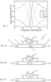
- Figure 1 shows power transmission lineshapes as a function of wavelength detuning for four cases corresponding to q values of -1, 0, 1, and 100.
- this is referred to as a symmetric Fano resonance, while in some literature, it is denoted as an inverse Lorentzian or an antiresonance.
- Fano q-parameter By carefully choosing the Fano q-parameter, it is possible to design an asymmetric Fano resonance in which the resonance frequency of the cavity is spectrally located anywhere between the transmission maximum and transmission minimum.
- the Fano transmission lineshapes corresponding to q values of -1, 0, and 1 are the characteristic lineshapes referred to previously.
- a waveguide-coupled cavity structure is said 'to be configured to exhibit Fano resonance', it is meant that when a coherent optical signal having a predetermined wavelength is coupled into the waveguide-coupled cavity structure, asymmetric Fano resonance (corresponding to q ⁇ -1 or 1) or symmetric Fano resonance (corresponding to q ⁇ 0 and also referred to as Inverse Lorentzian resonance) resulting from interference between the discrete mode and the continuum of modes will arise.
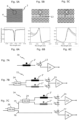
- Figure 2A illustrates a waveguide-coupled cavity structure 2 comprising an optical waveguide 4 that supports a continuum of modes and an optical cavity 6 supporting a discrete mode.
- the optical waveguide 4 has an input port 8 for receiving an optical signal and an output port 10 for providing an output optical signal.
- the structure is excited with light of frequency ⁇ s via the input port, and the transmitted light is collected from the output port.
- the cavity has a resonance frequency of ⁇ 0 , and its field amplitude is denoted by a ( t ).
- the cavity mode decays into the input and output ports with rates ⁇ 1 and ⁇ 2 , respectively.
- the out-of-plane decay rate is ⁇ in .
- the first term in Eq. (2) represents the detuning-dependence of the amplitude of the cavity field envelope, and its decay, while the second term represents the coupling of the input field to the cavity field.
- the amplitude of this path is determined by the amplitude transmission coefficient of a partially transmitting element (PTE) 13.
- PTE partially transmitting element
- the second term in Eq. (3) represents the contribution of the cavity field to the output field. The interference of these two terms gives rise to a Fano resonance.
- Figures 2A-C illustrates three different exemplary designs with different values of the Fano asymmetry parameter or q-parameter, q.
- the optical waveguide does not allow for direct transmission from the input port to the output port, transmission would only be possible via tunnelling through the cavity which would lead to conventional Fabry-Perot resonances with characteristic Lorentzian lineshape when the resonance is isolated from other modes.
- q 100 in Eq. (1) and shown as the dashed grey line In Figure 1 .
- the lineshape is a conventional Lorentzian lineshape at the cavity resonance with no features of interference between the discrete mode and the continuum of modes. Hence, this lineshape is not a Fano Resonance and is not the result of a structure exhibiting Fano-resonance.
- the optical waveguide of the waveguide-coupled cavity structure allows direct transmission of light from the input port to the output port.
- phase modulated coherent optical signals can be converted to intensity modulated signals by using the Fano resonance structure to change the amplitude-equality and phase relationships among the optical carrier and the optical sidebands.
- Fano resonance structure to change the amplitude-equality and phase relationships among the optical carrier and the optical sidebands.
- Figure 3A is a graph showing (solid grey line) a normalized optical spectrum of a 40 GHz phase modulated (PM) input signal.
- the PM spectrum is centred at 1550 nm, and it is composed of equidistant sidebands which are shifted by k times f m from the optical carrier, where f m is the phase modulation frequency.
- the graph also shows transmission spectrum of a waveguide-coupled cavity structure according to an embodiment of this disclosure exhibiting red-parity Fano resonance (solid black line), and the phase response (right ordinate) of the Fano resonance (dashed black line).
- the Abscissa in Fig. 1 is frequency whereas it in Fig. 3A is wavelength.
- Figure 3B shows the spectrum of the PM signal after transmission through the waveguide-coupled cavity structure according to an embodiment of this disclosure.
- the sideband amplitude and phases are altered proportional to the transmission lineshape of the Fano resonance.
- the minimum transmission of the transmission spectrum of the Fano resonance preferably overlaps with a sideband of the modulated coherent optical signal, as is the case in Figure 3A .
- the minimum transmission overlaps with the sideband having largest amplitude. This is advantageous since it gives rise to the strongest sideband suppression as is the case in Figure 3B .
- the resonance frequency of the optical cavity may be tuned to adjust the transmission spectrum of the Fano resonance in relation to the spectrum or carrier signal of the modulated coherent optical signal.
- the time-dependent power and phase of the input PM signal and the converted intensity and phase modulated signal are compared in Figures 3C and 3D , respectively.
- the input PM signal has a constant power of 1 mW (black line).
- SNR signal-to-noise ratio
- the phase of the input PM signal (grey line) oscillates sinusoidally within the range [0, 2 ⁇ ] at 40 GHz corresponding to a period of 25 ps.
- the converted signal in Fig. 3D shows oscillating power (black line) between 0 and 1.2 mW with the same oscillation period as the phase of the input PM signal.
- a higher peak power is observed in the PM-to-IM converted signal than the average power of the input PM signal.
- the phase of the PM-to-IM converted signal shown in Fig. 3D shows oscillations corresponding to the oscillation period of the PM input signal.
- the electrical power spectral density (PSD) of the input PM signal (black line) and the converted signal (grey line) are compared in Fig. 3E .
- the modulating radiofrequency (RF) signal at 40 GHz can be clearly seen in the electrical spectrum of the converted signal, whereas the modulating RF signal cannot be seen in the electrical spectrum of the input PM signal. This shows that amplitude imbalance between the sidebands has been achieved indicating intensity modulation in the converted signal. Note that the electrical spectrum of the PM signal is attenuated by 10 dB for visual clarity.
- the invention provides an optical receiver 1 for detecting a modulated coherent optical signal and comprising a waveguide-coupled cavity structure 2 described in relation to Figures 2A-C and a photodetector 12 arranged to receive the output optical signal from the output port 10.
- the waveguide-coupled cavity structure 2 is configured to exhibit Fano resonance as described in relation to Figures 1 and 2A-C .
- the waveguide-coupled cavity structure 2 is designed for a transmission spectrum of the Fano resonance to overlap with a spectrum of the modulated coherent optical signal to suppress transmission of at least one sideband of the modulated coherent optical signal through the structure, the sideband suppression being asymmetrical with respect to the carrier frequency of the modulated coherent optical signal, an example of this is illustrated in Figures 3A-B .
- the waveguide-coupled cavity structure 2 When a modulated coherent optical signal (example is illustrated in Figure 3C ) is input to the optical receiver 1 via input port 8, the waveguide-coupled cavity structure 2 provides a converted output optical signal (example is illustrated in Figure 3D ) via the output port 10.
- the photodetector 12, here a photodiode detects the power (black line in Figure 3D ) of the output optical signal from the output port 10, and the output photocurrent from the photodiode contains the information modulated on the modulated coherent optical signal. The photocurrent can then be processed by electrical signal processing.
- the waveguide-coupled cavity structure can be realized as an in-plane photonic crystal device as illustrated in Figure 4B.
- Figure 4B is a scanning electron microscope (SEM) image of an exemplary Fano structure realized using hexagonally arranged photonic crystal airholes on a 340 nm thick indium phosphide.
- the waveguide 14 is of line-defect type formed by removing one row of airholes, while the cavity 16 is an H0 nanocavity formed by shifting the airholes away from the center of the cavity.
- the typical radius of the airholes is around 120 nm, while the lattice constant of the photonic crystal is around 450 nm.
- the partially transmitting element is realized using a single airhole placed in the middle of the waveguide below the cavity.
- the resonance frequency of the optical cavity is tuned by thermo-optic effects, by heating of the material in which the photonic crystal structure of the cavity is formed.
- the optical receiver may comprise a heating element arranged to tune the resonance frequency of the optical cavity by heating the waveguide-coupled cavity structure.
- the waveguide-coupled cavity structure 2 can be realized as a ring resonator 18, including a racetrack resonator or loops of other shapes, side-coupled to a bus waveguide 20 as illustrated in Figure 4C and E .
- the ring resonator 18 and the accompanying bus waveguide 20 can be realized on silicon-on-insulator, glass or other III-V semiconductor platforms.
- the typical diameter of a ring resonator in an exemplary embodiment of the invention is few tens of micrometres.
- the ring resonator may be designed by means of its dimensions and material composition to have its resonance frequency at or near the carrier frequency of the received optical signal. Design-parameters of ring resonators are well known in the art.
- the resonance frequency of the ring resonator may be tuned using thermo-optic effects, by heating the material in which the ring resonator is formed.
- a ring resonator may be coupled to two waveguides 20 and 22 on opposite sides of the ring as shown in Figures 4D and E .
- the additional waveguide 22 has the technical effect of a loss channel for radiation out of the ring resonator enabling the transmission at the resonance to drop to zero, thereby providing the advantage of achieving a higher extinction ratio.
- This disclosure also provides a use and a method utilizing the waveguide-coupled cavity structure 2 described in relation to Figures 2A-C and comprised by the optical receiver 1.
- This use and method follow from the utilization of the waveguide-coupled cavity structure 2 already described and also cover the uses and method steps corresponding to the embodiments of the optical receiver described in the following.
- the waveguide-coupled cavity structures 2 described in relation to Figures 4A-C also embody an optical format converter according to an embodiment. Such optical format converters are equivalent to the receiver 1 omitting the photodetector 12.
- the use utilizing the waveguide-coupled cavity structure 2 for optical format conversion, preferably for converting a phase modulation format of a modulated coherent optical signal into an intensity modulation format, is also disclosed by the description of the receiver 1.
- the optical waveguide comprises a partially transmitting element (PTE) which affects the Fano asymmetry parameter of the waveguide-coupled cavity structure, see also the discussion of Eq. (1) previously.
- PTE partially transmitting element
- the phase of the coupling between the waveguide and the cavity can be altered depending on the position of the PTE, thus determining the spectral location of the constructive and destructive interferences referred to as the maximum and minimum transmission points in the transmission spectrum, respectively.
- the transmission coefficient of the waveguide can be controlled by the size of the PTE airhole. Large PTE radius results in low transmission of light through the waveguide.
- Figures 5A-C are scanning electron microscope (SEM) images of waveguide-coupled cavity structures 2 according to exemplary embodiments of the invention realized using hexagonally-arranged photonic crystal airholes.
- Figures 6A-C are graphs showing the corresponding theoretical (Eq. (1)) transmission spectra (solid black lines) and the measured transmission spectra (solid grey lines).
- the structure of Figure 5A exhibits a symmetric Fano (or inverse Lorentzian) resonance shown in Figure 6A .
- the cavity 6 is of quasi-H1 type formed by reducing the radius of the center airhole and shifting the airholes around the cavity away from the cavity center. Note that this structure does not have a PTE airhole in the waveguide.
- the structure of Figure 5B exhibits a red-parity Fano resonance shown in Figure 6B .
- the optical waveguide 4 comprises a PTE 13 located in the waveguide at the center plane with respect to the center of the cavity 16.
- the cavity 16 is of H0 type formed by shifting the airholes around the cavity away from the cavity center.
- the structure of Figure 5C exhibits a blue-parity Fano resonance shown in Figure 6C .
- the optical waveguide 4 comprises a PTE 13 located one lattice constant to the left of the center plane with respect to the cavity 16, hence breaking the mirror symmetry of the structure.
- the cavity 16 is of H0 type the same as Figure 5B .
- the waveguide is of W1-type formed by removing one row of airholes and shifting the inner most row of airholes towards the waveguide center. Assuming the same quality factor and cavity mode symmetry, the choice of quasi-H1 or H0 does not affect the lineshapes. However, an H0 cavity features larger mode confinement, and better overlap of the cavity mode with the material.
- a spectral position of the minimum transmission through the waveguide-coupled cavity structure is determined by parameters such as the resonance frequency and the quality factor of the cavity in addition to the placement of the PTE.
- waveguide-coupled cavity structures exhibiting symmetric Fano (inverse Lorentzian) resonance can be used for the conversion of phase-modulated signals to intensity-modulated signals
- structures exhibiting asymmetric Fano resonance are often advantageous as a larger extinction ratio between the maximum and minimum transmission can be achieved. This can be exploited to achieve a more efficient suppression of the phase modulated sidebands. Therefore, in a preferred embodiment, the waveguide-coupled cavity structure exhibits a blue or a red parity Fano resonance.
- a proposed receiver setup 70 for direct detection of binary phase-shift keying (BPSK) signals is shown in Figure 7A , in which the input BPSK signal is transmitted through a red-parity Fano device 2'. The output signal is then directly detected by a photodiode 12. The output photocurrent from the photodiode is then converted to voltage using transimpedance amplifier (TIA) 22.
- TIA transimpedance amplifier
- Different waveguide-coupled cavity structures can be used to convert a BPSK signal into intensity-modulated signal, based on either of symmetric or blue- or red-parity Fano resonances.
- This setup is similar to the receiver 1 described in relation to Figure 4A .
- the receiver setup 72 shown in Figure 7B can be used for converting quadrature phase-shift keying (QPSK) signal to intensity modulated signal enabling direct detection of QPSK signal.
- QPSK quadrature phase-shift keying
- the received optical signal is split into two arms by splitter 24, the arms containing structures exhibiting Fano resonances of opposite symmetry (red-parity structure 2' and blue parity structure 2").
- the time-dependent optical power of the signals after the blue and red-parity Fano are detected using a balanced photodiode setup 21.
- a balanced photodiode 21 comprises two photodiodes connected in series. It is also referred to as a balanced optical receiver and is designed for comparing photocurrent differences between two correlated optical signals while suppressing any common fluctuations of the input signals.
- the difference in photocurrents is sent to a transimpedance amplifier 22, which produces an output voltage proportional to the difference in photocurrents.
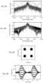
- Figures 8A-D are graphs illustrating numerical simulation results demonstrating the conversion of QPSK signal to intensity-modulated signal using the setup of Figure 7B .
- Figure 8A shows the normalized optical spectrum of the QPSK signal (grey line) and the transmission spectra of blue-parity (dashed black line) and red-parity (solid black line) Fano resonances.
- Figure 8B shows the normalized optical spectra of the signals after transmission through the blue-parity (black line) and red-parity (grey line) Fano resonances, respectively.
- Figure 8C shows the constellation diagram of the input QPSK signal with 15 dB SNR.
- Figure 8D shows the eye-diagram formed by superimposing the output voltage of 22 onto two symbol-slots is shown in Fig. 7(g). It shows seven-voltage levels corresponding to seven unique bit transitions.
- the optical receiver 72 is preferably configured to detect quadrature phase-shift keying signals in that it comprises:
- a proposed receiver setup 74 for direct detection of high order quadrature amplitude modulation (n-QAM) signals is shown in Figure 7C .
- intensity detection is also required compared to QPSK signals. Therefore, the received signal is split into phase detection branch 75 and an amplitude detection branch 76 by splitter 26.
- the signal in the phase detection branch 75 is further split into two arms by splitter 24, the arms containing Fano devices of opposite parities similar to the setup for detection of QPSK signals described in relation to Figure 7B above.
- the amplitude detection branch 76 is implemented using a direct detection scheme employing a photodiode 77 and TIA 78.
- High order quadrature amplitude modulation (n-QAM) are widely used for long-haul optical communication links due to their high system capacity, and increased spectral efficiency. Cost effective receivers that can detect n-QAM modulation formats are therefore highly needed.
- the optical receiver 74 is preferably configured to detect high order quadrature amplitude modulation signals in that it comprises, in addition to the optical receiver setup 72:
- the invention provides an optical communication kit 80 illustrated in Figure 9 .
- the optical communication kit 80 comprises an optical receiver 1 according to embodiments of the invention and an optical transmitter 82 comprising a coherent light source 86, typically a laser, and an optical modulator 88 for encoding incoming data onto light from the coherent light source to form a modulated coherent optical signal.
- the optical modulator 88 of the kit 80 comprises one or more optical phase modulators, such as solely optical phase modulators and no other modulators (e.g. an intensity modulator).
- the coherent optical signal would be provided by modulating only the phase of an optical carrier signal without modulating the amplitude of the optical carrier signal.
- This embodiment is suitable for QPSK systems and provides the advantage that the modulated coherent optical signal is optimised for detection by the optical receiver according to embodiments of the invention, thereby improving the quality of the generated intensity modulated signal. This provides the further advantage of a simpler and cheaper system since the transmitter and receiver would involve less components.
- the optical modulator 88 comprises at least one optical phase modulator and at least one amplitude or intensity modulator. This embodiment allows transmission and detection of advanced modulation formats such as 16-QAM signals.
- the optical modulator 88 would also comprise an amplitude modulator or more generally an I-Q modulator.
- An optical network including a waveguide, such as optical fiber link, 84 receives the modulated coherent optical signal from the optical transmitter 82 and ultimately delivers it to the optical receiver 1.
- the optical receiver 1 is described in relation to Figure 4A and receives and detects the modulated coherent optical signal to provide the data 'out' analogue to the encoded incoming data 'in'.
Landscapes
- Physics & Mathematics (AREA)
- Electromagnetism (AREA)
- Engineering & Computer Science (AREA)
- Computer Networks & Wireless Communication (AREA)
- Signal Processing (AREA)
- Optical Communication System (AREA)
Claims (15)
- Optischer Formatumsetzer zum Umsetzen eines Phasenmodulationsformats eines modulierten kohärenten optischen Signals in ein Intensitätsmodulationsformat, umfassend eine wellenleitergekoppelte Hohlraumstruktur (2, 2', 2"), die einen optischen Wellenleiter (4, 14, 20) umfasst, der einen Eingabeanschluss (8) zum Empfangen eines optischen Signals und einen Ausgabeanschluss (10) zum Bereitstellen eines optischen Ausgabesignals aufweist, wobei die wellenleitergekoppelte Hohlraumstruktur dazu konfiguriert ist, Fano-Resonanz vorzuweisen und wobei ein Übertragungsspektrum der Fano-Resonanz mit einem Spektrum eines empfangenen modulierten kohärenten optischen Signals überlappt, um die Übertragung von mindestens einem Seitenband des modulierten kohärenten optischen Signals durch die wellenleitergekoppelte Hohlraumstruktur zu unterdrücken, wobei die Seitenbandunterdrückung asymmetrisch in Bezug auf eine Trägerfrequenz des modulierten kohärenten optischen Signals ist.Ausgabe
- Optischer Formatumsetzer nach Anspruch 1, wobei ein Minimum in dem Übertragungsspektrum der Fano-Resonanz mit einem Seitenband des modulierten kohärenten optischen Signals überlappt.
- Optischer Formatumsetzer nach Anspruch 2, wobei das Minimum in dem Übertragungsspektrum mit einem Seitenband des modulierten kohärenten optischen Signals überlappt, das die größte Amplitude aufweist.
- Optischer Formatumsetzer nach einem der vorhergehenden Ansprüche, wobei der optische Wellenleiter ein Kontinuum von Moden unterstützt und wobei die wellenleitergekoppelte Hohlraumstruktur einen optischen Hohlraum (6, 16) umfasst, der ebenfalls eine diskrete Mode mit Resonanzfrequenz unterstützt, wobei der optische Wellenleiter innerhalb einer optischen Entfernung des optischen Hohlraums angeordnet ist, um eine evaneszente Anregung der diskreten Mode aus dem Mode-Kontinuum zu erlauben.
- Optischer Formatumsetzer nach einem der vorhergehenden Ansprüche, wobei der optische Wellenleiter ein teilweise übertragendes Element (PTE) (12) zum Steuern eines Fano-Asymmetrieparameters umfasst.
- Optischer Formatumsetzer nach einem der vorhergehenden Ansprüche, wobei die wellenleitergekoppelte Hohlraumstruktur ein Ringresonator (18) ist und wobei der optische Formatumsetzer ferner einen weiteren zusätzlichen optischen Wellenleiter (22) umfasst, der evaneszent an die wellenleitergekoppelte Hohlraumstruktur gekoppelt ist, um einen Verlustkanal für Strahlung aus dem Ringresonator bereitzustellen.
- Optischer Signalempfänger (1, 70, 72, 74) zum Detektieren eines modulierten kohärenten optischen Signals, umfassend den optischen Formatumsetzer nach einem der Ansprüche 1-6 und einen Photodetektor (12), der angeordnet ist, um das optische Ausgabesignal von dem Ausgabeanschluss zu empfangen.
- Optischer Empfänger nach Anspruch 7, wobei es sich bei der wellenleitergekoppelten Hohlraumstruktur um eine erste wellenleitergekoppelte Hohlraumstruktur (2') handelt, die dazu konfiguriert ist, eine Fano-Resonanz mit roter Parität vorzuweisen, wobei der optische Empfänger ferner Folgendes umfasst:eine zweite wellenleitergekoppelte Hohlraumstruktur (2"), die einen optischen Wellenleiter (4, 14, 20) umfasst, der einen Eingabeanschluss (8) zum Empfangen eines optischen Signals und einen Ausgabeanschluss (10) zum Bereitstellen eines optischen Ausgabesignals aufweist, wobei die wellenleitergekoppelte Hohlraumstruktur dazu konfiguriert ist, Fano-Resonanz mit blauer Parität vorzuweisen und wobei ein Übertragungsspektrum der Fano-Resonanz mit blauer Parität mit einem Spektrum eines empfangenen modulierten kohärenten optischen Signals überlappt, um Übertragung von mindestens einem Seitenband des modulierten kohärenten optischen Signals durch die zweite wellenleitergekoppelte Hohlraumstruktur zu unterdrücken, wobei die Seitenbandunterdrückung asymmetrisch in Bezug auf eine Trägerfrequenz des modulierten kohärenten optischen Signals ist;einem ersten Teiler (24) zum Aufteilen des modulierten kohärenten optischen Signals zwischen den Eingabeanschlüssen der ersten und der zweiten wellenleitergekoppelten Hohlraumstruktur; undeine balancierte Photodiode (21), die den Photodetektor umfasst und die an den Ausgängen der ersten und der zweiten wellenleitergekoppelten Hohlraumstruktur angeordnet ist.
- Optischer Empfänger nach Anspruch 8, ferner umfassend:
einen zweiten Teiler (26) zum Aufteilen des modulierten kohärenten optischen Signals zwischen einem Phasendetektionszweig und einem Amplitudenerfassungszweig, wobei der Phasendetektionszweig den ersten Teiler umfasst, der angeordnet ist, um das modulierte kohärente optische Signal von dem zweiten Teiler zu empfangen, und der Amplitudenerfassungszweig einen Photodetektor (77) umfasst, der angeordnet ist, um ein optisches Signal von dem zweiten Teiler zu empfangen. - Optisches Kommunikationspaket (80), umfassend:einen optischen Übertrager (82), der eine kohärente Lichtquelle (86) und mindestens einen optischen Phasenmodulator (88) zum Codieren von Daten auf Licht von der kohärenten Lichtquelle umfasst, um ein moduliertes kohärentes optisches Signal zu bilden;einen optischen Empfänger nach einem der Ansprüche 7-9 zum Empfangen und Detektieren des modulierten kohärenten optischen Signals.
- Optisches Kommunikationspaket nach Anspruch 10, wobei der optische Übertrager ferner mindestens einen optischen Intensitätsmodulator zum Codieren von Daten umfasst.
- Verwendung einer wellenleitergekoppelten Hohlraumstruktur (2, 2', 2"), die eine Fano-Resonanz zum Umsetzen der Phasenmodulation eines kohärenten optischen Signals in eine Intensitätsmodulation des optischen Signals vorweist, wobei das kohärente optische Signal in einen optischen Wellenleiter (4, 14, 20) der Hohlraumstruktur gekoppelt ist und wobei ein Übertragungsspektrum der Fano-Resonanz mit einem Spektrum des kohärenten optischen Signals überlappt, um Übertragung von mindestens einem Seitenband des kohärenten optischen Signals durch den optischen Wellenleiter zu unterdrücken, wobei die Seitenbandunterdrückung asymmetrisch in Bezug auf eine Trägerfrequenz des kohärenten optischen Signals ist.
- Verwendung nach Anspruch 12, wobei die Verwendung in einem optischen Empfänger (1, 70, 72, 74) zum Detektieren einer Phasenmodulation eines modulierten kohärenten optischen Signals erfolgt.
- Verfahren zum Umsetzen einer Phasenmodulation auf einem kohärenten optischen Signal in eine Intensitätsmodulation des optischen Signals, umfassend das Koppeln des kohärenten optischen Signals in einen optischen Wellenleiter einer wellenleitergekoppelten Hohlraumstruktur, die dazu konfiguriert ist, Fano-Resonanz vorzuweisen, wobei ein Übertragungsspektrum der Fano-Resonanz mit einem Spektrum des kohärenten optischen Signals überlappt, um Übertragung von mindestens einem Seitenband des kohärenten optischen Signals durch den optischen Wellenleiter zu unterdrücken, wobei die Seitenbandunterdrückung asymmetrisch in Bezug auf eine Trägerfrequenz des kohärenten optischen Signals ist.
- Verfahren zum Detektieren eines modulierten kohärenten optischen Signals, umfassend das Umsetzen einer Phasenmodulation des kohärenten optischen Signals in eine Intensitätsmodulation des optischen Signals unter Verwendung des Verfahrens nach Anspruch 14 und das Detektieren einer Intensitätsmodulation einer Ausgabe aus der wellenleitergekoppelten Hohlraumstruktur.
Applications Claiming Priority (2)
| Application Number | Priority Date | Filing Date | Title |
|---|---|---|---|
| EP21152503 | 2021-01-20 | ||
| PCT/EP2022/051158 WO2022157210A1 (en) | 2021-01-20 | 2022-01-19 | Direct detection of modulated coherent optical signals by means of a structure exhibiting fano resonance |
Publications (3)
| Publication Number | Publication Date |
|---|---|
| EP4282093A1 EP4282093A1 (de) | 2023-11-29 |
| EP4282093C0 EP4282093C0 (de) | 2025-02-12 |
| EP4282093B1 true EP4282093B1 (de) | 2025-02-12 |
Family
ID=74194540
Family Applications (1)
| Application Number | Title | Priority Date | Filing Date |
|---|---|---|---|
| EP22702890.9A Active EP4282093B1 (de) | 2021-01-20 | 2022-01-19 | Direkte detektion von modulierten kohärenten optischen signalen mittels einer struktur mit fano-resonanz |
Country Status (4)
| Country | Link |
|---|---|
| US (1) | US12431982B2 (de) |
| EP (1) | EP4282093B1 (de) |
| CN (1) | CN116711234A (de) |
| WO (1) | WO2022157210A1 (de) |
Families Citing this family (1)
| Publication number | Priority date | Publication date | Assignee | Title |
|---|---|---|---|---|
| CN120043615B (zh) * | 2025-04-01 | 2026-01-23 | 太原理工大学 | 一种基于法诺共振的高灵敏度声传感器及测量方法 |
Family Cites Families (29)
| Publication number | Priority date | Publication date | Assignee | Title |
|---|---|---|---|---|
| US6618148B1 (en) * | 2000-02-10 | 2003-09-09 | Southwest Sciences Incorporated | Acoustic resonance frequency locked photoacoustic spectrometer |
| JP4278332B2 (ja) | 2001-06-29 | 2009-06-10 | 日本電信電話株式会社 | 光送信器および光伝送システム |
| GB2389074B (en) | 2002-05-30 | 2005-06-08 | Louver Lite Ltd | Blind fabric |
| US7061335B2 (en) * | 2004-04-15 | 2006-06-13 | Oewaves, Inc. | Processing of signals with regenerative opto-electronic circuits |
| WO2007018552A2 (en) * | 2004-09-08 | 2007-02-15 | The Regents Of The University Of Michigan | High frequency ultrasound detection using polymer optical-ring resonator |
| JP5233115B2 (ja) | 2006-12-22 | 2013-07-10 | 日本電気株式会社 | Dqpsk復調方法を用いた光受信装置およびdqpsk復調方法 |
| WO2008118411A1 (en) | 2007-03-23 | 2008-10-02 | Massachusetts Institute Of Technology | Filter based dpsk receiver |
| JP5034770B2 (ja) | 2007-08-16 | 2012-09-26 | 富士通株式会社 | コヒーレント光受信器および光通信システム |
| US8032036B2 (en) | 2007-12-10 | 2011-10-04 | Verizon Patent And Licensing Inc. | DQPSK/DPSK optical receiver with tunable optical fibers |
| CN101555990A (zh) * | 2008-04-11 | 2009-10-14 | 电子科技大学 | 长距离管线安全监测系统 |
| JP2010206768A (ja) * | 2009-02-05 | 2010-09-16 | Nec Corp | 光送信装置及び方法 |
| JP5381400B2 (ja) * | 2009-02-06 | 2014-01-08 | セイコーエプソン株式会社 | 量子干渉装置、原子発振器、および磁気センサー |
| US8237514B2 (en) * | 2009-02-06 | 2012-08-07 | Seiko Epson Corporation | Quantum interference device, atomic oscillator, and magnetic sensor |
| US8301037B2 (en) * | 2010-03-05 | 2012-10-30 | Alcatel Lucent | Iterative carrier-phase estimation and data recovery for coherent optical receivers |
| CN103259098B (zh) * | 2013-05-16 | 2015-07-29 | 大连理工大学 | 一种可以产生法诺共振增强和频率可调谐现象的多层对称超材料 |
| EP3103202B1 (de) * | 2014-02-07 | 2018-03-21 | Danmarks Tekniske Universitet | Dekodierung eines kombinierten amplitudenmodulierten und frequenzmodulierten signals |
| US10191215B2 (en) * | 2015-05-05 | 2019-01-29 | Ecole Polytechnique Federale De Lausanne (Epfl) | Waveguide fabrication method |
| US10075245B2 (en) | 2015-05-08 | 2018-09-11 | Massachusetts Institute Of Technology | Apparatus and methods for reconfigurable optical receivers |
| US9696492B1 (en) * | 2016-03-03 | 2017-07-04 | National Technology & Engineering Solutions Of Sandia, Llc | On-chip photonic-phononic emitter-receiver apparatus |
| US10313022B2 (en) | 2016-09-27 | 2019-06-04 | Raytheon Company | Active demodulation systems and methods for optical signals |
| US10164765B2 (en) | 2017-02-10 | 2018-12-25 | Raytheon Company | Receivers and method for detecting a non-persistent communication superimposed on an overt communication channel |
| AU2018265770B2 (en) * | 2017-05-12 | 2022-12-01 | Australian National University | A frequency conversion device and process |
| CN108072631B (zh) * | 2017-12-11 | 2023-07-18 | 华侨大学 | 基于石墨烯七聚体法诺共振的折射率传感器及其制作方法 |
| JP7110386B2 (ja) * | 2018-04-12 | 2022-08-01 | レイセオン カンパニー | 光信号における位相変化検出 |
| US10739390B2 (en) * | 2018-07-17 | 2020-08-11 | United States Of America As Represented By The Secretary Of The Navy | Resonantly-enhanced optical phase detection of RF signals in LiNBO3 |
| CN109669239B (zh) | 2019-01-04 | 2020-10-02 | 深圳大学 | 一种光子晶体波导正交分裂模干涉fano共振结构 |
| EP3918305B1 (de) * | 2019-01-28 | 2022-11-30 | Universiteit Gent | Photoakustischer wandler |
| CN110441858B (zh) | 2019-07-15 | 2020-07-31 | 南京邮电大学 | 三角晶格二维光子晶体Fano共振器 |
| CN112039601B (zh) * | 2020-09-28 | 2021-08-13 | 南京航空航天大学 | 星间自零差相干光载射频通信方法及链路 |
-
2022
- 2022-01-19 EP EP22702890.9A patent/EP4282093B1/de active Active
- 2022-01-19 CN CN202280009549.XA patent/CN116711234A/zh active Pending
- 2022-01-19 US US18/258,168 patent/US12431982B2/en active Active
- 2022-01-19 WO PCT/EP2022/051158 patent/WO2022157210A1/en not_active Ceased
Also Published As
| Publication number | Publication date |
|---|---|
| EP4282093C0 (de) | 2025-02-12 |
| US12431982B2 (en) | 2025-09-30 |
| US20240056196A1 (en) | 2024-02-15 |
| WO2022157210A1 (en) | 2022-07-28 |
| CN116711234A (zh) | 2023-09-05 |
| EP4282093A1 (de) | 2023-11-29 |
Similar Documents
| Publication | Publication Date | Title |
|---|---|---|
| EP2267923B1 (de) | Optisches Übertragungssystem | |
| Du et al. | Silicon-based decoder for polarization-encoding quantum key distribution | |
| Yamamoto et al. | Coherent optical fiber transmission systems | |
| EP2107418B1 (de) | Optisches qam-system umfassend einen optischen modulator und eine regelungsvorrichtung und verfahren zur steuerung des optischen modulators | |
| US9515736B2 (en) | Systems for differential optical signaling | |
| US10901153B2 (en) | Null bias mach-zehnder interferometer with ring resonators | |
| Schindler et al. | Monolithic GaAs electro-optic IQ modulator demonstrated at 150 Gbit/s with 64QAM | |
| CN101277150A (zh) | 电光调制器产生相移键控信号缺陷的在线监测方法 | |
| EP4282093B1 (de) | Direkte detektion von modulierten kohärenten optischen signalen mittels einer struktur mit fano-resonanz | |
| Wu et al. | Low-chirp push-pull dual-ring modulator with 144 Gb/s PAM-4 data transmission | |
| CN116566486A (zh) | 一种高阶模外差探测自由空间激光通信系统及通信方法 | |
| US20070274732A1 (en) | Optical Modulation Converter and Method for Converting the Modulation Format of an Optical Signal | |
| US12375178B2 (en) | Control device, compensation device, program, and control method | |
| Chang et al. | Low-chirp push-pull microring modulators | |
| Li et al. | 10-Gb/s BPSK link using silicon microring resonators for modulation and demodulation | |
| Yang et al. | CD-insensitive PMD monitoring based on RF power measurement | |
| Li et al. | A C-band push-pull dual-ring silicon photonic modulator for 20 km SSMF transmission without CD compensation | |
| Naughton et al. | Error-free 10Gb/s duobinary transmission over 215km of SSMF using a hybrid photonic integrated reflective modulator | |
| Zhang et al. | Silicon microring-resonator-based modulation and demodulation of DQPSK Signals | |
| US20090290827A1 (en) | Nonlinear optical loop mirrors | |
| Lyubomirsky | Advanced modulation formats for ultra-dense wavelength division multiplexing | |
| Gui et al. | Experimental demonstration of quadrature phase-shift keying silicon ring modulator based on intensity modulation | |
| Chang et al. | Differential microring binary phase-shift keying modulators | |
| Bédard et al. | Transmission of 50 Gb/s with a dual phase-shift Bragg grating silicon photonic modulator | |
| Zhang et al. | Novel orthogonal modulation format DRZ-FSK/DPSK for high-speed long-haul optical communication |
Legal Events
| Date | Code | Title | Description |
|---|---|---|---|
| STAA | Information on the status of an ep patent application or granted ep patent |
Free format text: STATUS: UNKNOWN |
|
| STAA | Information on the status of an ep patent application or granted ep patent |
Free format text: STATUS: THE INTERNATIONAL PUBLICATION HAS BEEN MADE |
|
| PUAI | Public reference made under article 153(3) epc to a published international application that has entered the european phase |
Free format text: ORIGINAL CODE: 0009012 |
|
| STAA | Information on the status of an ep patent application or granted ep patent |
Free format text: STATUS: REQUEST FOR EXAMINATION WAS MADE |
|
| 17P | Request for examination filed |
Effective date: 20230626 |
|
| AK | Designated contracting states |
Kind code of ref document: A1 Designated state(s): AL AT BE BG CH CY CZ DE DK EE ES FI FR GB GR HR HU IE IS IT LI LT LU LV MC MK MT NL NO PL PT RO RS SE SI SK SM TR |
|
| DAV | Request for validation of the european patent (deleted) | ||
| DAX | Request for extension of the european patent (deleted) | ||
| GRAP | Despatch of communication of intention to grant a patent |
Free format text: ORIGINAL CODE: EPIDOSNIGR1 |
|
| STAA | Information on the status of an ep patent application or granted ep patent |
Free format text: STATUS: GRANT OF PATENT IS INTENDED |
|
| INTG | Intention to grant announced |
Effective date: 20240916 |
|
| GRAS | Grant fee paid |
Free format text: ORIGINAL CODE: EPIDOSNIGR3 |
|
| GRAA | (expected) grant |
Free format text: ORIGINAL CODE: 0009210 |
|
| STAA | Information on the status of an ep patent application or granted ep patent |
Free format text: STATUS: THE PATENT HAS BEEN GRANTED |
|
| AK | Designated contracting states |
Kind code of ref document: B1 Designated state(s): AL AT BE BG CH CY CZ DE DK EE ES FI FR GB GR HR HU IE IS IT LI LT LU LV MC MK MT NL NO PL PT RO RS SE SI SK SM TR |
|
| REG | Reference to a national code |
Ref country code: GB Ref legal event code: FG4D |
|
| REG | Reference to a national code |
Ref country code: CH Ref legal event code: EP |
|
| REG | Reference to a national code |
Ref country code: DE Ref legal event code: R096 Ref document number: 602022010499 Country of ref document: DE |
|
| REG | Reference to a national code |
Ref country code: IE Ref legal event code: FG4D |
|
| U01 | Request for unitary effect filed |
Effective date: 20250212 |
|
| U07 | Unitary effect registered |
Designated state(s): AT BE BG DE DK EE FI FR IT LT LU LV MT NL PT RO SE SI Effective date: 20250218 |
|
| PG25 | Lapsed in a contracting state [announced via postgrant information from national office to epo] |
Ref country code: RS Free format text: LAPSE BECAUSE OF FAILURE TO SUBMIT A TRANSLATION OF THE DESCRIPTION OR TO PAY THE FEE WITHIN THE PRESCRIBED TIME-LIMIT Effective date: 20250512 |
|
| PG25 | Lapsed in a contracting state [announced via postgrant information from national office to epo] |
Ref country code: PL Free format text: LAPSE BECAUSE OF FAILURE TO SUBMIT A TRANSLATION OF THE DESCRIPTION OR TO PAY THE FEE WITHIN THE PRESCRIBED TIME-LIMIT Effective date: 20250212 |
|
| PG25 | Lapsed in a contracting state [announced via postgrant information from national office to epo] |
Ref country code: ES Free format text: LAPSE BECAUSE OF FAILURE TO SUBMIT A TRANSLATION OF THE DESCRIPTION OR TO PAY THE FEE WITHIN THE PRESCRIBED TIME-LIMIT Effective date: 20250212 |
|
| PG25 | Lapsed in a contracting state [announced via postgrant information from national office to epo] |
Ref country code: IS Free format text: LAPSE BECAUSE OF FAILURE TO SUBMIT A TRANSLATION OF THE DESCRIPTION OR TO PAY THE FEE WITHIN THE PRESCRIBED TIME-LIMIT Effective date: 20250612 Ref country code: NO Free format text: LAPSE BECAUSE OF FAILURE TO SUBMIT A TRANSLATION OF THE DESCRIPTION OR TO PAY THE FEE WITHIN THE PRESCRIBED TIME-LIMIT Effective date: 20250512 |
|
| PG25 | Lapsed in a contracting state [announced via postgrant information from national office to epo] |
Ref country code: HR Free format text: LAPSE BECAUSE OF FAILURE TO SUBMIT A TRANSLATION OF THE DESCRIPTION OR TO PAY THE FEE WITHIN THE PRESCRIBED TIME-LIMIT Effective date: 20250212 |
|
| PG25 | Lapsed in a contracting state [announced via postgrant information from national office to epo] |
Ref country code: GR Free format text: LAPSE BECAUSE OF FAILURE TO SUBMIT A TRANSLATION OF THE DESCRIPTION OR TO PAY THE FEE WITHIN THE PRESCRIBED TIME-LIMIT Effective date: 20250513 |
|
| PG25 | Lapsed in a contracting state [announced via postgrant information from national office to epo] |
Ref country code: SM Free format text: LAPSE BECAUSE OF FAILURE TO SUBMIT A TRANSLATION OF THE DESCRIPTION OR TO PAY THE FEE WITHIN THE PRESCRIBED TIME-LIMIT Effective date: 20250212 |
|
| PG25 | Lapsed in a contracting state [announced via postgrant information from national office to epo] |
Ref country code: CZ Free format text: LAPSE BECAUSE OF FAILURE TO SUBMIT A TRANSLATION OF THE DESCRIPTION OR TO PAY THE FEE WITHIN THE PRESCRIBED TIME-LIMIT Effective date: 20250212 |
|
| PG25 | Lapsed in a contracting state [announced via postgrant information from national office to epo] |
Ref country code: SK Free format text: LAPSE BECAUSE OF FAILURE TO SUBMIT A TRANSLATION OF THE DESCRIPTION OR TO PAY THE FEE WITHIN THE PRESCRIBED TIME-LIMIT Effective date: 20250212 |
|
| PLBE | No opposition filed within time limit |
Free format text: ORIGINAL CODE: 0009261 |
|
| STAA | Information on the status of an ep patent application or granted ep patent |
Free format text: STATUS: NO OPPOSITION FILED WITHIN TIME LIMIT |
|
| REG | Reference to a national code |
Ref country code: CH Ref legal event code: L10 Free format text: ST27 STATUS EVENT CODE: U-0-0-L10-L00 (AS PROVIDED BY THE NATIONAL OFFICE) Effective date: 20251224 |
|
| 26N | No opposition filed |
Effective date: 20251113 |
|
| REG | Reference to a national code |
Ref country code: CH Ref legal event code: U11 Free format text: ST27 STATUS EVENT CODE: U-0-0-U10-U11 (AS PROVIDED BY THE NATIONAL OFFICE) Effective date: 20260201 |
|
| U20 | Renewal fee for the european patent with unitary effect paid |
Year of fee payment: 5 Effective date: 20260106 |
|
| PGFP | Annual fee paid to national office [announced via postgrant information from national office to epo] |
Ref country code: GB Payment date: 20260106 Year of fee payment: 5 |