EP4280830A1 - Foldable mechanism and foldable terminal - Google Patents
Foldable mechanism and foldable terminal Download PDFInfo
- Publication number
- EP4280830A1 EP4280830A1 EP22879623.1A EP22879623A EP4280830A1 EP 4280830 A1 EP4280830 A1 EP 4280830A1 EP 22879623 A EP22879623 A EP 22879623A EP 4280830 A1 EP4280830 A1 EP 4280830A1
- Authority
- EP
- European Patent Office
- Prior art keywords
- swing arm
- pressing plate
- groove
- fastening
- sliding
- Prior art date
- Legal status (The legal status is an assumption and is not a legal conclusion. Google has not performed a legal analysis and makes no representation as to the accuracy of the status listed.)
- Granted
Links
Images








Classifications
-
- H—ELECTRICITY
- H04—ELECTRIC COMMUNICATION TECHNIQUE
- H04M—TELEPHONIC COMMUNICATION
- H04M1/00—Substation equipment, e.g. for use by subscribers
- H04M1/02—Constructional features of telephone sets
- H04M1/0202—Portable telephone sets, e.g. cordless phones, mobile phones or bar type handsets
- H04M1/0206—Portable telephones comprising a plurality of mechanically joined movable body parts, e.g. hinged housings
- H04M1/0208—Portable telephones comprising a plurality of mechanically joined movable body parts, e.g. hinged housings characterized by the relative motions of the body parts
- H04M1/0214—Foldable telephones, i.e. with body parts pivoting to an open position around an axis parallel to the plane they define in closed position
- H04M1/0216—Foldable in one direction, i.e. using a one degree of freedom hinge
- H04M1/022—The hinge comprising two parallel pivoting axes
-
- H—ELECTRICITY
- H04—ELECTRIC COMMUNICATION TECHNIQUE
- H04M—TELEPHONIC COMMUNICATION
- H04M1/00—Substation equipment, e.g. for use by subscribers
- H04M1/02—Constructional features of telephone sets
- H04M1/0202—Portable telephone sets, e.g. cordless phones, mobile phones or bar type handsets
- H04M1/0206—Portable telephones comprising a plurality of mechanically joined movable body parts, e.g. hinged housings
- H04M1/0208—Portable telephones comprising a plurality of mechanically joined movable body parts, e.g. hinged housings characterized by the relative motions of the body parts
- H04M1/0214—Foldable telephones, i.e. with body parts pivoting to an open position around an axis parallel to the plane they define in closed position
- H04M1/0216—Foldable in one direction, i.e. using a one degree of freedom hinge
-
- G—PHYSICS
- G06—COMPUTING OR CALCULATING; COUNTING
- G06F—ELECTRIC DIGITAL DATA PROCESSING
- G06F1/00—Details not covered by groups G06F3/00 - G06F13/00 and G06F21/00
- G06F1/16—Constructional details or arrangements
- G06F1/1613—Constructional details or arrangements for portable computers
- G06F1/1633—Constructional details or arrangements of portable computers not specific to the type of enclosures covered by groups G06F1/1615 - G06F1/1626
- G06F1/1637—Details related to the display arrangement, including those related to the mounting of the display in the housing
- G06F1/1652—Details related to the display arrangement, including those related to the mounting of the display in the housing the display being flexible, e.g. mimicking a sheet of paper, or rollable
-
- G—PHYSICS
- G06—COMPUTING OR CALCULATING; COUNTING
- G06F—ELECTRIC DIGITAL DATA PROCESSING
- G06F1/00—Details not covered by groups G06F3/00 - G06F13/00 and G06F21/00
- G06F1/16—Constructional details or arrangements
- G06F1/1613—Constructional details or arrangements for portable computers
- G06F1/1633—Constructional details or arrangements of portable computers not specific to the type of enclosures covered by groups G06F1/1615 - G06F1/1626
- G06F1/1675—Miscellaneous details related to the relative movement between the different enclosures or enclosure parts
- G06F1/1681—Details related solely to hinges
-
- H—ELECTRICITY
- H05—ELECTRIC TECHNIQUES NOT OTHERWISE PROVIDED FOR
- H05K—PRINTED CIRCUITS; CASINGS OR CONSTRUCTIONAL DETAILS OF ELECTRIC APPARATUS; MANUFACTURE OF ASSEMBLAGES OF ELECTRICAL COMPONENTS
- H05K5/00—Casings, cabinets or drawers for electric apparatus
- H05K5/0017—Casings, cabinets or drawers for electric apparatus with operator interface units
-
- H—ELECTRICITY
- H05—ELECTRIC TECHNIQUES NOT OTHERWISE PROVIDED FOR
- H05K—PRINTED CIRCUITS; CASINGS OR CONSTRUCTIONAL DETAILS OF ELECTRIC APPARATUS; MANUFACTURE OF ASSEMBLAGES OF ELECTRICAL COMPONENTS
- H05K5/00—Casings, cabinets or drawers for electric apparatus
- H05K5/02—Details
- H05K5/0217—Mechanical details of casings
-
- H—ELECTRICITY
- H04—ELECTRIC COMMUNICATION TECHNIQUE
- H04M—TELEPHONIC COMMUNICATION
- H04M1/00—Substation equipment, e.g. for use by subscribers
- H04M1/02—Constructional features of telephone sets
- H04M1/0202—Portable telephone sets, e.g. cordless phones, mobile phones or bar type handsets
- H04M1/026—Details of the structure or mounting of specific components
- H04M1/0266—Details of the structure or mounting of specific components for a display module assembly
- H04M1/0268—Details of the structure or mounting of specific components for a display module assembly including a flexible display panel
Definitions
- This application relates to the field of foldable terminals, and in particular, to a foldable mechanism and a foldable terminal.
- a foldable terminal usually implements folding and unfolding by using a foldable mechanism.
- an existing foldable mechanism usually needs a large quantity of components to implement folding and unfolding, and consequently the foldable mechanism has a complex structure, which is not conducive to a lightweight design of a foldable terminal.
- This application provides a foldable mechanism and a foldable terminal, to simplify a structure of the foldable mechanism and implement a lightweight design of the foldable terminal.
- this application provides a foldable mechanism, including a base and a pressing plate assembly.
- the pressing plate assembly is mounted on the base.
- the pressing plate assembly includes a first pressing plate and a first pressing plate swing arm.
- the first pressing plate is an integrally formed structural member.
- a sliding portion of the first pressing plate swing arm is slidably connected to the first pressing plate, to implement slidable connection between the first pressing plate swing arm and the first pressing plate.
- a rotating portion of the first pressing plate swing arm is rotatably connected to the base, to implement rotatable connection between the first pressing plate swing arm and the base.
- the first pressing plate is an integrally formed structural member. This not only can improve overall strength of the first pressing plate to ensure structural stability of the first pressing plate, but also can reduce components of the pressing plate assembly to facilitate assembling of the foldable mechanism, thereby helping improve assembly precision between the pressing plate assembly and another component, and helping implement a lightweight design of the foldable mechanism.
- the first pressing plate includes a support portion and an auxiliary portion.
- the auxiliary portion is fixedly connected to a bottom surface of the support portion, and the auxiliary portion is provided with a sliding hole, or the auxiliary portion and the support portion form a sliding hole through enclosing.
- the sliding portion of the first pressing plate swing arm penetrates through the sliding hole, and can slide with respect to the first pressing plate in the sliding hole, to implement slidable connection between the sliding portion of the first pressing plate swing arm and the first pressing plate.
- the support portion and the auxiliary portion are integrally formed.
- the first pressing plate further includes a guide slider.
- the guide slider is fixedly connected to the bottom surface of the support portion, and is spaced apart from the auxiliary portion.
- the foldable mechanism further includes a connecting assembly.
- the connecting assembly is mounted on the base, and is connected to the pressing plate assembly.
- the connecting assembly includes a first fastening bracket.
- the first fastening bracket is slidably and rotatably connected to the first pressing plate.
- the first fastening bracket is provided with a guide groove.
- the guide slider is mounted in the guide groove, and can slide and rotate with respect to the first fastening bracket in the guide groove, to implement slidable and rotatable connection between the first pressing plate and the first fastening bracket.
- the pressing plate assembly in the foldable mechanism further includes a second pressing plate and a second pressing plate swing arm.
- the second pressing plate is an integrally formed structural member.
- a sliding portion of the second pressing plate swing arm is slidably connected to the second pressing plate, to implement slidable connection between the second pressing plate swing arm and the second pressing plate.
- a rotating portion of the second pressing plate swing arm is rotatably connected to the base, to implement slidable connection between the second pressing plate swing arm and the base.
- the second pressing plate is an integrally formed structural member. This not only can improve overall strength of the second pressing plate to ensure structural stability of the second pressing plate, but also can reduce components of the pressing plate assembly to facilitate assembling of the foldable mechanism, thereby helping improve assembly precision between the pressing plate assembly and another component, and helping implement a lightweight design of the foldable mechanism.
- the second pressing plate includes a support portion and an auxiliary portion.
- the auxiliary portion is fixedly connected to a bottom surface of the support portion, and the auxiliary portion is provided with a sliding hole, or the auxiliary portion and the support portion form a sliding hole through enclosing.
- the sliding portion of the second pressing plate swing arm penetrates through the sliding hole, and can slide with respect to the second pressing plate in the sliding hole, to implement slidable connection between the sliding portion of the second pressing plate swing arm and the second pressing plate.
- the support portion and the auxiliary portion are integrally formed.
- the foldable mechanism further includes a flexible support plate, and the flexible support plate is mounted on the pressing plate assembly.
- the flexible support plate is mounted on the first pressing plate swing arm and the second pressing plate swing arm, and can be bent under the driving of the first pressing plate swing arm and/or the second pressing plate swing arm.
- a bending direction of the flexible support plate is parallel to rotation centers of the first pressing plate swing arm and the second pressing plate swing arm with respect to the base.
- the support surface can support a foldable part of a display screen. This not only can ensure good display of the display screen, but also can ensure that when the foldable part is touched, the foldable part is not likely to be damaged or dented due to an external force touch, thereby improving reliability of using the display screen.
- the flexible support plate is not designed with a hole, and the top surface of the flexible support plate is a complete plane. Therefore, the support surface has a relatively large area, and can better support the foldable part, to improve an effect of supporting the foldable part by the flexible support plate.
- a connecting portion of the first pressing plate swing arm is provided with an assembly hole
- a connecting portion of the second pressing plate swing arm is provided with an assembly hole
- the flexible support plate includes a flexible support portion, a first fastening portion, and a second fastening portion. Both the first fastening portion and the second fastening portion are fixedly connected to a bottom surface of the flexible support portion, and are spaced apart from each other.
- the first fastening portion is mounted in the assembly hole on the first pressing plate swing arm, and the second fastening portion is mounted in the assembly hole on the second pressing plate swing arm, to implement assembling between the flexible support plate and the pressing plate assembly.
- the flexible support portion is provided with a plurality of strip-shaped grooves, and the plurality of strip-shaped grooves are arranged in parallel and spaced apart from each other.
- An extension direction of each strip-shaped groove is parallel to the bending direction of the flexible support plate, to ensure flexibility of the flexible support plate.
- openings of all of the plurality of strip-shaped grooves are located on a bottom surface of the flexible support plate, to ensure integrity of the top surface of the flexible support plate.
- the strip-shaped groove is recessed from the bottom surface of the flexible support plate in a direction far away from the top surface, and runs through a front end face and a rear end face of the flexible support plate.
- the strip-shaped groove is spaced apart from both the first fastening portion and the second fastening portion.
- the rotating portion of the first pressing plate swing arm is slidably and rotatably connected to the base
- the rotating portion of the second pressing plate swing arm is slidably and rotatably connected to the base
- each of the first pressing plate swing arm and the second pressing plate swing arm When rotating with respect to the base, each of the first pressing plate swing arm and the second pressing plate swing arm produces displacement with the base, and the displacement produced by each of the first pressing plate swing arm and the second pressing plate swing arm matches a size change caused by bending of the flexible support plate, to ensure flatness of the flexible support plate and prevent the flexible support plate from being pleated.
- the connecting assembly in the foldable mechanism further includes a second fastening bracket, and the second fastening bracket is slidably and rotatably connected to the second pressing plate.
- the first pressing plate and the second pressing plate are disposed opposite to each other, the first pressing plate, the second pressing plate, the first fastening bracket, the second fastening bracket, and the flexible support plate form avoidance space through enclosing, and the avoidance space is in a water drop shape.
- the avoidance space can avoid an R angle formed when the foldable part is bent, so that the foldable part is not greatly bent, to avoid a poor phenomenon such as a crease on the display screen, and help prolong a service life of the display screen.
- the base is provided with an avoidance groove, and when the foldable mechanism is in the folded state, the avoidance groove is used to avoid a bottom of the flexible support plate, so that interference between the base and the flexible support plate can be avoided, to help form the avoidance space in the water drop shape.
- the second pressing plate further includes a guide slider.
- the guide slider is fixedly connected to the bottom surface of the support portion, and is spaced apart from the auxiliary portion.
- the second fastening bracket is provided with a guide groove.
- the guide slider is mounted in the guide groove, and can slide and rotate with respect to the second fastening bracket in the guide groove, to implement slidable and rotatable connection between the second pressing plate and the second fastening bracket.
- the connecting assembly in the foldable mechanism further includes a first primary swing arm and a second primary swing arm.
- a rotating portion of the first primary swing arm is rotatably connected to the first fastening bracket, to implement rotatable connection between the first primary swing arm and the first fastening bracket.
- a sliding portion of the first primary swing arm is slidably and rotatably connected to the base, to implement slidable and rotatable connection between the first primary swing arm and the base.
- a rotating portion of the second primary swing arm is rotatably connected to the second fastening bracket, to implement rotatable connection between the second primary swing arm and the second fastening bracket.
- a sliding portion of the second primary swing arm is slidably and rotatably connected to the base, to implement slidable and rotatable connection between the second primary swing arm and the base.
- the flexible support portion is further provided with a first avoidance groove and a second avoidance groove, and openings of both the first avoidance groove and the second avoidance groove are located on the bottom surface of the flexible support portion.
- the first avoidance groove is used to avoid the sliding portion of the first primary swing arm
- the second avoidance groove is used to avoid the sliding portion of the second primary swing arm, to avoid interference between the flexible support plate and each of the first primary swing arm and the second primary swing arm, so that the flexible support portion does not abut against the first primary swing arm or the second primary swing arm, and does not protrude with respect to the top surface of the first pressing plate and the top surface of the second pressing plate, to ensure that the top surface of the flexible support plate is flush with the top surface of the first pressing plate and the top surface of the second pressing plate.
- Each of the first avoidance groove and the second avoidance groove communicates with one or more strip-shaped grooves.
- the connecting assembly in the foldable mechanism further includes a first secondary swing arm and a second secondary swing arm.
- a sliding portion of the first secondary swing arm is slidably connected to the first fastening bracket, to implement slidable connection between the first secondary swing arm and the first fastening bracket.
- a rotating portion of the first secondary swing arm is rotatably connected to the base, to implement rotatable connection between the first secondary swing arm and the base.
- a sliding portion of the second secondary swing arm is slidably connected to the second fastening bracket, to implement slidable connection between the second secondary swing arm and the second fastening bracket.
- a rotating portion of the second secondary swing arm is rotatably connected to the base, to implement rotatable connection between the second secondary swing arm and the base.
- the flexible support portion is further provided with a third avoidance groove and a fourth avoidance groove, and openings of both the third avoidance groove and the fourth avoidance groove are located on the bottom surface of the flexible support portion.
- the third avoidance groove is used to avoid the rotating portion of the first secondary swing arm
- the fourth avoidance groove is used to avoid the rotating portion of the second secondary swing arm, to avoid interference between the flexible support plate and each of the first secondary swing arm and the second secondary swing arm, so that the flexible support portion does not abut against the first secondary swing arm or the second secondary swing arm, and does not protrude with respect to the top surface of the first pressing plate and the top surface of the second pressing plate, to ensure that the top surface of the flexible support plate is flush with the top surface of the first pressing plate and the top surface of the second pressing plate.
- Each of the third avoidance groove and the fourth avoidance groove communicates with one or more strip-shaped grooves.
- the foldable mechanism further includes a damping assembly, and the damping assembly is mounted on the connecting assembly.
- the damping assembly can provide damping force during folding or unfolding of the connecting assembly with respect to the base.
- the damping assembly includes a first damping member and a second damping member.
- the first damping member is mounted on the first fastening bracket, is fixedly connected to the first secondary swing arm, and can slide with respect to the first fastening bracket under the driving of the first secondary swing arm.
- the second damping member is mounted on the second fastening bracket, is fixedly connected to the second secondary swing arm, and can slide with respect to the second fastening bracket under the driving of the second secondary swing arm.
- the foldable mechanism When the foldable mechanism is applied to the foldable terminal, in a process of using the foldable terminal by a user, for example, when the foldable terminal is in a folded state or an unfolded state and the foldable terminal is switched between the folded state and the unfolded state, the user can obviously feel the damping force provided by the damping assembly, and the user can experience a relatively good hand feeling, thereby improving user experience.
- the foldable mechanism further includes a synchronization part, and the synchronization part is mounted on the base, and is slidably connected to the connecting assembly.
- the synchronization part is slidably connected to the first secondary swing arm and the second secondary swing arm, so that the first secondary swing arm and the second secondary swing arm synchronously rotate with respect to the base.
- the rotating portion of the first secondary swing arm is provided with a first spiral groove
- the rotating portion of the second secondary swing arm is provided with a second spiral groove
- a synchronization assembly includes a fastening post and a synchronization slider.
- the fastening post is mounted on the base.
- the synchronization slider is mounted on the fastening post, and can slide with respect to the fastening post.
- a first cam of the synchronization slider is mounted in the first spiral groove, and can slide with respect to the rotating portion of the first secondary swing arm in the first spiral groove.
- a second cam of the synchronization slider is mounted in the second spiral groove, and can slide with respect to the rotating portion of the second secondary swing arm in the second spiral groove.
- the first cam slides with respect to the rotating portion of the first secondary swing arm in the first spiral groove, to drive the slider to slide with respect to the fastening post, and drive the second cam to slide with respect to the rotating portion of the second secondary swing arm in the second spiral groove, so as to drive the second secondary swing arm to rotate with respect to the base, thereby implementing synchronous rotation between the first secondary swing arm and the second secondary swing arm.
- the synchronization part can drive the first secondary swing arm to rotate with respect to the base, thereby implementing synchronous rotation between the first secondary swing arm and the second secondary swing arm.
- this application provides a foldable terminal, including a first housing, a second housing, and any one of the foregoing foldable mechanisms.
- the foldable mechanism is connected between the first housing and the second housing.
- a first pressing plate is an integrally formed structural member. This not only can improve overall strength of the first pressing plate to ensure structural stability of the first pressing plate, but also can reduce components of a pressing plate assembly to facilitate assembling of the foldable mechanism, thereby helping improve assembly precision between the pressing plate assembly and another component, and helping implement a lightweight design of the foldable terminal.
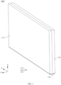
- FIG. 1 is a schematic diagram of a structure of a foldable terminal 1000 in a state according to an embodiment of this application.
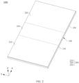
- FIG. 2 is a schematic diagram of a structure of the foldable terminal 1000 shown in FIG. 1 in a second state.
- the foldable terminal 1000 may be a foldable electronic product such as a mobile phone, a tablet computer, a personal computer, a multimedia player, an e-book reader, a notebook computer, a vehicle-mounted device, or a wearable device.
- the foldable terminal 1000 is a foldable mobile phone. That is, the foldable terminal 1000 is a mobile phone that can be switched between a folded state and an unfolded state.
- a length direction of the shown foldable terminal 1000 is defined as an X-axis direction
- a length direction of the foldable terminal 1000 is defined as a Y-axis direction
- a thickness direction of the foldable terminal 1000 is defined as a Z-axis direction. Every two of the X-axis direction, the Y-axis direction, and the Z-axis direction are perpendicular to each other. It should be noted that qualifiers such as parallel and perpendicular for a relative position relationship in this embodiment of this application are all for a current process level, and are not absolutely strict definitions in the mathematical sense, a slight deviation is allowed, and approximately parallel and approximately perpendicular are acceptable.
- a is parallel to B means that A is parallel or approximately parallel to B, and an angle between A and B may range from 0 degrees to 10 degrees.
- a is perpendicular to B means that A is perpendicular or approximately perpendicular to B, and an angle between A and B may range from 80 degrees to 100 degrees.
- an extension direction of a rotation axis of the foldable terminal 1000 is the Y-axis direction. That is, the foldable terminal 1000 can be relatively unfolded or relatively folded in the Y-axis direction.
- the foldable terminal 1000 shown in FIG. 1 is in the folded state, the foldable terminal 1000 is smaller in size in the X-axis direction, and it is easy to carry the foldable terminal 1000.
- the foldable terminal 1000 shown in FIG. 2 is in the unfolded state, the foldable terminal 1000 is larger in size in the X-axis direction, and the foldable terminal 1000 has a larger display area.
- an unfolding angle ⁇ of the foldable terminal 1000 shown in FIG. 2 is 180 degrees. That is, the foldable terminal 1000 shown in FIG. 2 is in the unfolded state.
- an unfolding angle ⁇ of the foldable terminal 1000 shown in FIG. 2 is 180 degrees means that ⁇ may be 180 degrees or approximately 180 degrees, for example, 170 degrees, 175 degrees, 185 degrees, or 190 degrees.
- An angle used as an example for description in the following may be understood in a same way.
- the foldable terminal 1000 shown in this embodiment of this application is a terminal that can be folded once.
- the foldable terminal 1000 may be a terminal that can be folded for a plurality of times (twice or more).
- the foldable terminal 1000 may include a plurality of parts, and two adjacent parts may be folded relatively close to each other until the foldable terminal 1000 is in the folded state, or two adjacent parts may be unfolded relatively away from each other until the foldable terminal 1000 is in the unfolded state.
- FIG. 3 is a schematic diagram of an exploded structure of the foldable terminal 1000 shown in FIG. 2 .
- the foldable terminal 1000 includes a foldable apparatus 100 and a display screen 200, and the display screen 200 is mounted on the foldable apparatus 100.
- the display screen 200 includes a display surface (not shown in the figure) facing away from the foldable apparatus 100, and the display surface is used to display information such as texts, images, or videos.
- the display screen 200 includes a first display part 210, a second display part 220, and a foldable part 230, and the foldable part 230 is connected between the first display part 210 and the second display part 220.
- the foldable part 230 can be bent in the Y-axis direction.
- the foldable terminal 1000 when the foldable terminal 1000 is in the folded state, the first display part 210 and the second display part 220 are disposed opposite to each other, and the foldable part 230 is bent. In this case, the display screen 200 is in a folded state, and an exposed area of the display screen 200 is relatively small, to greatly reduce a probability that the display screen 200 is damaged, and effectively protect the display screen 200.
- FIG. 2 when the foldable terminal 1000 is in the unfolded state, the first display part 210 and the second display part 220 are unfolded with respect to each other, and the foldable part 230 is unfolded without bending. In this case, an angle between the foldable part 230 and each of the first display part 210 and the second display part 220 is ⁇ , and the display screen 200 has a large display region, to implement large-screen display by the foldable terminal 1000 and improve user experience.
- FIG. 4 is a schematic diagram of an exploded structure of the foldable apparatus 100 in the foldable terminal 1000 shown in FIG. 3 .
- the foldable apparatus 100 includes a first housing 110, a second housing 120, and a foldable mechanism 130, and the foldable mechanism 130 is connected between the first housing 110 and the second housing 120, to implement rotatable connection between the first housing 110 and the second housing 120.
- the first housing 110 carries the first display part 210
- the second housing 120 carries the second display part 220.
- the first display part 210 is mounted on the first housing 110
- the second display part 220 is mounted on the second housing 120.
- the foldable mechanism 130 is disposed opposite to the foldable part 230.
- the first housing 110 and the second housing 120 may rotate with respect to each other through the foldable mechanism 130, so that the foldable apparatus 100 is switched between a folded state and an unfolded state.
- the first housing 110 and the second housing 120 may rotate with respect to each other to be disposed opposite to each other, so that the foldable apparatus 100 is in the folded state, as shown in FIG. 1 .
- the foldable mechanism 130 is in a folded state.
- the first housing 110 and the second housing 120 may alternatively rotate with respect to each other to be unfolded with respect to each other, so that the foldable apparatus 100 is in the unfolded state, as shown in FIG. 2 .
- the foldable mechanism 130 is in an unfolded state.
- the foldable terminal 1000 shown in FIG. 2 is in the unfolded state
- an angle between the first housing 110 and the second housing 120 is ⁇ .
- the foldable mechanism 130 is in the unfolded state.
- the first housing 110 is provided with a first accommodating groove 1101, and the first accommodating groove 1101 is located on a side that is of the first housing 110 and that faces the second housing 120.
- An opening of the first accommodating groove 1101 is located on a top surface of the first housing 110.
- the first accommodating groove 1101 is recessed in a direction from the top surface to a bottom surface of the first housing 110, and runs through a right side surface of the first housing 110.
- the second housing 120 and the first housing 110 have a same structure and are mirror-symmetrical with respect to the foldable mechanism 130.
- the second housing 120 is provided with a second accommodating groove 1201, and the second accommodating groove 1201 is located on a side that is of the second housing 120 and that faces the first housing 110.
- An opening of the second accommodating groove 1201 is located on a top surface of the second housing 120.
- the second accommodating groove 1201 is recessed in a direction from the top surface to a bottom surface of the second housing 120, and runs through a side surface that is of the second housing 120 and that faces the first housing 110.
- the foldable apparatus 100 When the foldable apparatus 100 is in an unfolded state, that is, when the angle between the first housing 110 and the second housing 120 is ⁇ , the first accommodating groove 1101 and the second accommodating groove 1201 form accommodating space 1301 through enclosing.
- the foldable mechanism 130 is mounted in the accommodating space 1301. A part of the foldable mechanism 130 is mounted in the first accommodating groove 1101 on the first housing 110, and a part of the foldable mechanism 130 is mounted in the second accommodating groove 1201 on the second housing 120.
- orientation words such as “top”, “bottom”, “left”, “right”, “front” and “back” used in this embodiment of this application to describe the foldable terminal 1000 are mainly explained based on a display orientation of the foldable terminal 1000 in FIG. 2 , with “top” facing a positive direction of a Z-axis, “bottom” facing a negative direction of the Z-axis, “right” facing a positive direction of an X-axis, “left” facing a negative direction of the X-axis, “back” facing a positive direction of a Y-axis, and “front” facing a negative direction of the Y-axis.
- This does not limit the orientation of the foldable terminal 1000 in an actual application scenario.
- a pressing plate is usually formed by assembling a plurality of components. Consequently, there are a large quantity of components in the pressing plate, and assembly is complex. In addition, a problem of poor assembly precision is likely to occur, resulting in a complex structure of the foldable mechanism, which is not conducive to a lightweight design of a foldable terminal.
- a structure of the foldable mechanism 130 in the foldable terminal 1000 shown in this embodiment of this application is described below.
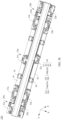
- FIG. 5a is a schematic diagram of a structure of the foldable mechanism 130 in the foldable apparatus 100 shown in FIG. 4 .
- FIG. 5b is a schematic diagram of a structure of the foldable mechanism 130 shown in FIG. 5a from another perspective.
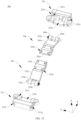
- FIG. 6 is a schematic diagram of an exploded structure of the foldable mechanism 130 shown in FIG. 5a .
- the foldable mechanism 130 includes a base 10, a connecting assembly 20, a damping assembly 30, a pressing plate assembly 40, and a flexible support plate 50. Both the connecting assembly 20 and the pressing plate assembly 40 are mounted on the base 10, and can be folded or unfolded with respect to the base 10, so as to be switched between a folded state and an unfolded state.
- the damping assembly 30 is mounted on the connecting assembly 20, and can be folded or unfolded with respect to the base 10 under the driving of the connecting assembly 20, so as to be switched between a folded state and an unfolded state.
- the flexible support plate 50 is mounted on the pressing plate assembly 40, and can be relatively folded or relatively unfolded under the driving of the pressing plate assembly 40, so as to be switched between a folded state and an unfolded state.
- the base 10 extends in the Y-axis direction.
- the three connecting assemblies 20 are a first connecting assembly 20a, a second connecting assembly 20b, and a third connecting assembly 20c.
- the third connecting assembly 20c is located between the first connecting assembly 20a and the second connecting assembly 20b.
- the first connecting assembly 20a is located on a front side of the foldable mechanism 130
- the second connecting assembly 20b is located on a rear side of the foldable mechanism 130
- the third connecting assembly 20c is located in a middle portion of the foldable mechanism 130.
- a quantity of connecting assemblies 20 is not specifically limited in this application.
- the first connecting assembly 20a includes a first fastening bracket 21a, a second fastening bracket 22a, a first primary swing arm 23a, a second primary swing arm 24a, a first secondary swing arm 25a, and a second secondary swing arm 26a.
- the first primary swing arm 23a is rotatably connected to the first fastening bracket 21a, and is slidably and rotatably connected to the base 10.
- the second primary swing arm 24a is rotatably connected to the second fastening bracket 22a, and is slidably and rotatably connected to the base 10.
- the first secondary swing arm 25a is slidably connected to the first fastening bracket 21a, and is rotatably connected to the base 10.
- the second secondary swing arm 26a is slidably connected to the second fastening bracket 22a, and is rotatably connected to the base 10.
- a direction in which the first fastening bracket 21a, the first primary swing arm 23a, and the first secondary swing arm 25a rotate with respect to the base 10 is a first direction
- a direction in which the second fastening bracket 22a, the second primary swing arm 24a, and the second secondary swing arm 26a rotate with respect to the base 10 is a second direction.
- the second direction is opposite to the first direction.
- the first connecting assembly 20a when the first connecting assembly 20a is switched from the folded state to the unfolded state, the first fastening bracket 21a, the first primary swing arm 23a, and the first secondary swing arm 25a rotate with respect to the base 10 in a counterclockwise direction, and the second fastening bracket 22a, the second primary swing arm 24a, and the second secondary swing arm 26a rotate with respect to the base 10 in a clockwise direction.
- the first connecting assembly 20a is switched from the unfolded state to the folded state
- the first primary swing arm 23a and the first secondary swing arm 25a rotate with respect to the base 10 in the clockwise direction
- the second primary swing arm 24a and the second secondary swing arm 26a rotate with respect to the base 10 in the counterclockwise direction.
- the second connecting assembly 20b and the first connecting assembly 20a may be a same or similar assembly, symmetrical or partially symmetrical structures, or different structures.
- the second connecting assembly 20b may be centrally symmetrical with the first connecting assembly 20a.
- a connection relationship between components, and a connection relationship between the component and a component outside the assembly refer to the related design of the first connecting assembly 20a.
- the second connecting assembly 20b and the first connecting assembly 20a may differ in detailed structure or position arrangement of the component.
- the second connecting assembly 20b includes a first fastening bracket 21b, a second fastening bracket 22b, a first primary swing arm 23b, a second primary swing arm 24b, a first secondary swing arm 25b, and a second secondary swing arm 26b.
- first connecting assembly 20a For a structure of each component in the second connecting assembly 20b and a connection relationship between each component and each of the base 10, the pressing plate assembly 40, and the damping assembly 30, refer to the related description of the first connecting assembly 20a.
- the third connecting assembly 20c includes a first fastening bracket 21c, a second fastening bracket 22c, a first primary swing arm 23c, and a second primary swing arm 24c.
- first fastening bracket 21c a structure of each component in the third connecting assembly 20c and a connection relationship between each component and each of the base 10, the pressing plate assembly 40, and the damping assembly 30, refer to the related description of the first connecting assembly 20a.
- the third connecting assembly 20c may further include a first secondary swing arm and a second secondary swing arm (not shown in the figure). This is not specifically limited in this application.
- first fastening bracket 21a in the first connecting assembly 20a, the first fastening bracket 21b in the second connecting assembly 20b, and the first fastening bracket 21c in the third connecting assembly 20c may be structural members independent of each other, or may be a plurality of parts of an integrated structural member; and/or the second fastening bracket 22a in the first connecting assembly 20a, the second fastening bracket 22b in the second connecting assembly 20b, and the second fastening bracket 22c in the third connecting assembly 20c may be structural members independent of each other, or may be a plurality of parts of an integrated structural member.
- the foldable mechanism 130 further includes a synchronization part 60, and the synchronization part 60 is mounted on the base 10, and is slidably connected to the connecting assembly 20.
- there are two synchronization parts 60 and the two synchronization parts 60 are spaced apart from each other in the Y-axis direction.
- the two synchronization parts 60 are a first synchronization part 60a and a second synchronization part 60b.
- the first synchronization part 60a is mounted on a front side of the base 10, and is slidably connected to the first secondary swing arm 25a and the second secondary swing arm 26a, so that the first secondary swing arm 25a and the second secondary swing arm 26a synchronously rotate with respect to the base 10.
- the second synchronization part 60b is mounted on a rear side of the base 10, and is slidably connected to the first secondary swing arm 25b and the second secondary swing arm 26b, so that the first secondary swing arm 25b and the second secondary swing arm 26b synchronously rotate with respect to the base 10.
- the second synchronization part 60b and the first synchronization part 60a may be a same or similar assembly, symmetrical or partially symmetrical structures, or different structures.
- the second synchronization part 60b may be mirror-symmetrical with the first synchronization part 60a.
- a connection relationship between components, and a connection relationship between the component and a component outside an assembly refer to the related design of the first synchronization part 60a.
- the second synchronization part 60b and the first synchronization part 60a may differ in detailed structure or position arrangement of the component.
- damping assemblies 30 there are two damping assemblies 30, and the two damping assemblies 30 are spaced apart from each other in the Y-axis direction.
- the two damping assemblies 30 are a first damping assembly 30a and a second damping assembly 30b.
- the first damping assembly 30a is mounted on the first connecting assembly 20a.
- the first damping assembly 30a can provide damping force during folding or unfolding of the first connecting assembly 20a with respect to the base 10.
- the second damping assembly 30b is mounted on the second connecting assembly 20b.
- the second damping assembly 30b can provide damping force during folding or unfolding of the second connecting assembly 20b with respect to the base 10.
- the user can obviously feel the damping force provided by the first damping assembly 30a and the second damping assembly 30b, and the user can experience a relatively good hand feeling, thereby improving user experience.
- damping assemblies 30 there may be three damping assemblies 30.
- the three damping assemblies 30 are a first damping assembly 30a, a second damping assembly 30b, and a third damping assembly (not shown in the figure).
- the third damping assembly is mounted on the third connecting assembly 20c.
- the third damping assembly can provide damping force during folding or unfolding of the third connecting assembly 20c with respect to the base 10.
- a quantity of damping assemblies 30 is not specifically limited in this application.
- the first damping assembly 30a includes a first damping member 31a and a second damping member 32a.
- the first damping member 31a is mounted on the first fastening bracket 21a, is fixedly connected to the first secondary swing arm 25a, and can slide with respect to the first fastening bracket 21a under the driving of the first secondary swing arm 25a.
- the second damping member 32a is mounted on the second fastening bracket 22a, is fixedly connected to the second secondary swing arm 26a, and can slide with respect to the second fastening bracket 22a under the driving of the second secondary swing arm 26a.
- the second damping assembly 30b and the first damping assembly 30a may be a same or similar assembly, symmetrical or partially symmetrical structures, or different structures.
- the second damping assembly 30b may be mirror-symmetrical with the first damping assembly 30a.
- a connection relationship between components, and a connection relationship between the component and a component outside the assembly refer to the related design of the first damping assembly 30a.
- the second damping assembly 30b and the first damping assembly 30a may differ in detailed structure or position arrangement of the component.
- the second damping assembly 30b includes a first damping member 31b and a second damping member 32b.
- the first damping member 31b is mounted on the first fastening bracket 21b, is fixedly connected to the first secondary swing arm 25b, and can slide with respect to the first fastening bracket 21b under the driving of the first secondary swing arm 25b.
- the second damping member 32b is mounted on the second fastening bracket 22b, is fixedly connected to the second secondary swing arm 26b, and can slide with respect to the second fastening bracket 22b under the driving of the second secondary swing arm 26b.
- the pressing plate assembly 40 is slidably and rotatably connected to the connecting assembly 20.
- the pressing plate assembly 40 includes a first pressing plate 41, a second pressing plate 42, a first pressing plate swing arm 43, and a second pressing plate swing arm 44.
- a front side of the first pressing plate 41 is slidably and rotatably connected to the first fastening bracket 21a
- a rear side of the first pressing plate 41 is slidably and rotatably connected to the first fastening bracket 21b
- a middle portion of the first pressing plate 41 is slidably and rotatably connected to the first fastening bracket 21c.
- a front side of the second pressing plate 42 is slidably and rotatably connected to the second fastening bracket 22a, a rear side of the second pressing plate 42 is slidably and rotatably connected to the second fastening bracket 22b, and a middle portion of the second pressing plate 42 is slidably and rotatably connected to the second fastening bracket 22c.
- first pressing plate swing arms 43 and four second pressing plate swing arms 44 There are four first pressing plate swing arms 43 and four second pressing plate swing arms 44. In the Y-axis direction, the four first pressing plate swing arms 43 are spaced apart from each other, and the four second pressing plate swing arms 44 are spaced apart from each other. In some other embodiments, there may be one, two, or at least four first pressing plate swing arms 43, and/or there may be one, two, or at least four second pressing plate swing arms 44. Quantities of first pressing plate swing arms 43 and second pressing plate swing arms 44 are not specifically limited in this application.
- Each first pressing plate swing arm 43 is slidably connected to the first pressing plate 41, and is slidably and rotatably connected to the base 10.
- Each second pressing plate swing arm 44 is slidably connected to the second pressing plate 42, and is slidably and rotatably connected to the base 10.
- each first pressing plate swing arm 43 may be rotatably connected to the base 10, and/or the second pressing plate swing arm 44 may be rotatably connected to the base 10.
- the flexible support plate 50 is mounted on the first pressing plate swing arm 43 and the second pressing plate swing arm 44, and can be relatively folded or relatively unfolded under the driving of the first pressing plate swing arm 43 and the second pressing plate swing arm 44, to implement switching between the folded state and the unfolded state.
- a bending direction of the flexible support plate 50 is the Y-axis direction, and is parallel to rotation centers of the first pressing plate swing arm 43 and the second pressing plate swing arm 44 with respect to the base 10. It should be noted that, that a bending direction of the flexible support plate 50 is the Y-axis means that the flexible support plate 50 can be bent in the Y-axis direction.
- FIG. 7 is a schematic diagram of a structure of the base 10 in the foldable mechanism 130 shown in FIG. 6 .
- the base 10 includes a shaft cover 11, a first bracket 12, a second bracket 13, and a third bracket 14. All of the first bracket 12, the second bracket 13, and the third bracket 14 are fixedly connected to the shaft cover 11. In the Y-axis direction, the third bracket 14 is located between the first bracket 12 and the second bracket 13, and is spaced apart from both the first bracket 12 and the second bracket 13.
- the base 10 may be an integrally formed structural member. This not only can improve overall strength of the base 10 to ensure the overall strength of the base 10, but also can reduce a quantity of components in the base 10 to facilitate a lightweight design of the foldable mechanism 130.
- the shaft cover 11 includes a front end portion 11a, a rear end portion 11b, and a middle portion 11c.
- the middle portion 11c is connected between the front end portion 11a and the rear end portion 11b.
- the front end portion 11a, the middle portion 11c, and the rear end portion 11b are sequentially arranged in the Y-axis direction.
- the front end portion 11a, the rear end portion 11b, and the middle portion 11c are integrally formed.
- the shaft cover 11 is an integrally formed structural member.
- the front end portion 11a, the rear end portion 11b, and the middle portion 11c may be assembled to form an integrated structural member.
- the shaft cover 11 is an integrated structural member formed through assembling.
- the first bracket 12 and a part of the third bracket 14 are fixedly connected to the front end portion 11a of the shaft cover 11, and jointly form a first part 10a of the base 10 with the front end portion 11a of the shaft cover 11.
- the second bracket 13 and a part of the third bracket 14 are fixedly connected to the rear end portion 11b of the shaft cover 11, and jointly form a second part 10b of the base 10 with the rear end portion 11b of the shaft cover 11.
- a part of the third bracket 14 is fixedly connected to the middle portion 11c of the shaft cover 11, and jointly forms a third part 10c of the base 10 with the middle portion 11c of the shaft cover 11.
- the first part 10a of the base 10 is cooperatively connected to the first connecting assembly 20a
- the second part 10b of the base 10 is cooperatively connected to the second connecting assembly 20b
- the third part 10c of the base 10 is cooperatively connected to the third connecting assembly 20c.
- FIG. 8 is a schematic diagram of a structure of the first part 10a of the base 10 shown in FIG. 7 .
- the front end portion 11a of the shaft cover 11 is provided with a mounting groove 111a, and an opening of the mounting groove 111a is located on a top surface (not shown in the figure) of the front end portion 11a.
- the mounting groove 111a is recessed in a direction (the negative direction of the Z-axis shown in the figure) from the top surface to a bottom surface (not shown in the figure) of the front end portion 11a. Specifically, the mounting groove 111a is located in a middle portion of the front end portion 11a.
- the front end portion 11a of the shaft cover 11 is further provided with a positioning rod 112a.
- the positioning rod 112a is disposed on a groove bottom wall (not shown in the figure) of the mounting groove 111a.
- the positioning rod 112a extends in the positive direction of the Z-axis from the groove bottom wall of the mounting groove 111a.
- the positioning rod 112a is in a cylindrical shape.
- the positioning rod 112a may alternatively be in a square column shape or a specially-shaped column shape, and/or there may be one, two, or at least four positioning rods 112a.
- the first bracket 12 is provided with an avoidance groove 121 and a positioning hole 122.
- An opening of the avoidance groove 121 is located on a top surface of the first bracket 12. Specifically, the opening of the avoidance groove 121 is located in a middle region of the top surface of the first bracket 12.
- the avoidance groove 121 is recessed in a direction (the negative direction of the Z-axis shown in the figure) from the top surface to a bottom surface of the first bracket 12, and runs through a front end face and a rear end face of the first bracket 12.
- the avoidance groove 121 is an arc-shaped groove. That is, a groove bottom wall of the avoidance groove 121 has an arc-shaped surface.
- An opening of the positioning hole 122 is located on the bottom surface (not shown in the figure) of the first bracket 12.
- the positioning hole 122 is recessed in a direction (the positive direction of the Z-axis shown in the figure) from the bottom surface to the top surface (not shown in the figure) of the first bracket 12, and runs through the groove bottom wall of the avoidance groove 121.
- Each positioning hole 122 is adapted to one positioning rod 112a.
- two positioning rods 112a can pass through the two positioning holes 122, to implement positioning between the first bracket 12 and the shaft cover 11, and ensure assembly precision between the first bracket 12 and the shaft cover 11.
- the first bracket 12 is further provided with a first notch 123, a second notch 124, a third notch 125, and a fourth notch 126. Openings of all of the first notch 123, the second notch 124, the third notch 125, and the fourth notch 126 are located on the top surface of the first bracket 12. All of the first notch 123, the second notch 124, the third notch 125, and the fourth notch 126 are recessed in a direction (the Z-axis direction shown in the figure) from the top surface to the bottom surface of the first bracket 12, and run through the bottom surface of the first bracket 12 and the groove bottom wall of the avoidance groove 121.
- both the first notch 123 and the third notch 125 are located on a left side of the first bracket 12, and run through a left side surface of the first bracket 12.
- Both the second notch 124 and the fourth notch 126 are located on a right side of the first bracket 12, and run through a right side surface of the first bracket 12.
- the first notch 123 and the second notch 124 are spaced apart from each other in the Y-axis direction.
- the first notch 123 and the second notch 124 partially overlap in the X-axis direction. That is, projections of the first notch 123 and the second notch 124 on an X-Z plane partially overlap.
- the first notch 123 and the second notch 124 partially reuse space of the first bracket 12 in the X-axis direction, to help reduce a size of the first bracket 12 in the X-axis direction, and help reduce a size of the foldable mechanism 130 in the X-axis direction, so as to help reduce a size of the foldable terminal 1000 in the X-axis direction, and help implement a miniaturization design of the foldable terminal 1000.
- first notch 123 and the second notch 124 may partially or completely overlap in the Y-axis direction, to reduce a size of the first bracket 12 in the Y-axis direction; or the first notch 123 and the second notch 124 may be spaced apart from each other or completely overlap in the X-axis direction.
- the third notch 125 is located on a side that is of the first notch 123 and that faces the positive direction of the Y-axis, and is spaced apart from the first notch 123.
- the fourth notch 126 is located on a side that is of the second notch 124 and that faces the positive direction of the Y-axis, and is spaced apart from the second notch 124.
- the third notch 125 and the fourth notch 126 are spaced apart and disposed opposite to each other in the X-axis direction.
- the third notch 125 and the fourth notch 126 completely overlap in the Y-axis direction. That is, projections of the third notch 125 and the fourth notch 126 on a Y-Z plane completely overlap.
- the third notch 125 and the fourth notch 126 reuse space of the first bracket 12 in the Y-axis direction, to help reduce a size of the first bracket 12 in the Y-axis direction, and help reduce a size of the foldable mechanism 130 in the Y-axis direction, so as to help reduce a size of the foldable terminal 1000 in the Y-axis direction, and help implement a miniaturization design of the foldable terminal 1000.
- the third notch 125 and the fourth notch 126 may partially or completely overlap in the X-axis direction, to reduce a size of the first bracket 12 in the X-axis direction; or the third notch 125 and the fourth notch 126 may be spaced apart from each other or partially overlap in the Y-axis direction.
- first bracket 12 is further provided with a first slider 12a, a second slider 12b, a third slider 12c, and a fourth slider 12d.
- first sliders 12a There are two first sliders 12a, and the two first sliders 12a are respectively disposed on two groove side walls of the first notch 123.
- One first slider 12a extends in the negative direction of the Y-axis from the groove side wall of the first notch 123, and the other first slider 12a extends in the positive direction of the Y-axis from the groove side wall of the first notch 123.
- the two first sliders 12a are spaced apart and disposed opposite to each other in the Y-axis direction.
- Each of the two first sliders 12a is in a shape of an arc-shaped plate, and is recessed toward the negative direction of the Z-axis. That is, both a top surface (not shown in the figure) and a bottom surface (not shown in the figure) of the first slider 12a are arc-shaped surfaces, and are recessed toward the negative direction of the Z-axis.
- axes of the two first sliders 12a are both parallel to the Y-axis, and the two first sliders 12a are coaxial.
- coaxial in this embodiment of this application means that extension lines of axes coincide with each other.
- a and B are coaxial means that an extension line of an axis of A coincides with an extension line of an axis of B.
- coaxial may be understood in a same way.
- the two second sliders 12b are respectively disposed on two groove side walls of the second notch 124
- the two third sliders 12c are respectively disposed on two groove side walls of the third notch 125
- the two fourth sliders 12d are respectively disposed on two groove side walls of the fourth notch 126.
- first bracket 12 is further provided with a first rotating shaft hole (not shown in the figure) and a second rotating shaft hole 127. Openings of both the first rotating shaft hole and the second rotating shaft hole 127 are located on the rear end face of the first bracket 12. Both the first rotating shaft hole and the second rotating shaft hole 127 extend in the positive direction of the Y-axis from the rear end face of the first bracket 12. Specifically, the first rotating shaft hole is located on the left side of the first bracket 12, and the second rotating shaft hole 127 is located on the right side of the first bracket 12.
- both the first rotating shaft hole and the second rotating shaft hole 127 are circular holes, and axes are both parallel to the Y-axis direction.
- first bracket 12 is further provided with a mounting bump 12e, and the mounting bump 12e is disposed on the rear end face of the first bracket 12.
- the mounting bump 12e is located between the first rotating shaft hole and the second rotating shaft hole 127, and is spaced apart from both the first rotating shaft hole and the second rotating shaft hole 127.
- the mounting bump 12e extends in the negative direction of the Y-axis from the rear end face of the first bracket 12.
- the mounting bump 12e is provided with a mounting hole 128, and an opening of the mounting hole 128 is located on a rear end face of the mounting bump 12e.
- the mounting hole 128 is recessed from the rear end face of the mounting bump 12e in the positive direction of the Y-axis.
- the mounting hole 128 is a square hole. In some other embodiments, the mounting hole 128 may be a circular hole or another specially-shaped hole.
- the first bracket 12 may be fixedly connected to the front end portion 11a by using a fastener (for example, a screw or a pin). Specifically, the first bracket 12 is mounted in the mounting groove 111a, and is located at a position that is of the mounting groove 111a and that faces away from the middle portion 11c.
- a fastener for example, a screw or a pin.
- the first notch 123 and a part of the mounting groove 111a jointly form a first sliding groove 101a
- the second notch 124 and a part of the mounting groove 111a jointly form a second sliding groove 102a
- the third notch 125 and a part of the mounting groove 111a jointly form a first fitting groove 103a
- the fourth notch 126 and a part of the mounting groove 111a jointly form a second fitting groove 104a.
- the first bracket 12 may be fixedly connected to the front end portion 11a of the shaft cover 11 through bonding, welding, or the like.
- FIG. 9 is a schematic diagram of a structure of the second part 10b of the base 10 shown in FIG. 7 .
- the rear end portion 11b of the shaft cover 11 is centrally symmetrical with the front end portion 11a of the shaft cover 11. This not only can improve symmetry of the shaft cover 11, but also can simplify an overall structure of the shaft cover 11, thereby reducing processing costs of the shaft cover 11. It may be understood that, for a structural design of the rear end portion 11b of the shaft cover 11, reference may be made to the related solution of the front end portion 11a (shown in FIG. 8 ) of the shaft cover 11, and the rear end portion 11b of the shaft cover 11 is allowed to be slightly different from the front end portion 11a of the shaft cover 11 in detailed structure or position arrangement of the component.
- the rear end portion 11b of the shaft cover 11 is provided with a mounting groove 111b and a positioning rod 112b.
- the rear end portion 11b of the shaft cover 11 may be mirror-symmetrical with the front end portion 11a of the shaft cover 11, the rear end portion 11b of the shaft cover 11 may be partially symmetrical with the front end portion 11a of the shaft cover 11, or the rear end portion 11b of the shaft cover 11 and the front end portion 11a of the shaft cover 11 may be of a same or similar structure or different structures.
- the second bracket 13 is centrally symmetrical with the first bracket 12. This not only can improve symmetry of the base 10, but also can simplify an overall structure of the base 10, thereby reducing processing costs of the base 10. It may be understood that, for a basic design of a structure of a component of the second bracket 13, a design of a position relationship between components, and a design of a connection relationship between the second bracket 13 and the rear end portion 11b of the shaft cover 11, reference may be made to the related solution of the first bracket 12 (shown in FIG. 8 ), and the second bracket 13 is allowed to be slightly different from the first bracket 12 in detailed structure or position arrangement of the component.
- the second bracket 13 is provided with an avoidance groove 131, a positioning hole 132, a first notch 133, a second notch 134, a third notch 135, a fourth notch 136, a first rotating shaft hole, and a second rotating shaft hole (not shown in the figure).
- the first notch 133 and a part of the mounting groove 111b jointly form a first sliding groove 101b.
- the second notch 134 and a part of the mounting groove 111b jointly form a second sliding groove 102b.
- the third notch 135 and a part of the mounting groove 111b jointly form a first fitting groove 103b.
- the fourth notch 136 and a part of the mounting groove 111b jointly form a second fitting groove 104b. Openings of both the first rotating shaft hole and the second rotating shaft hole are located on a front end face of the second bracket 13.
- the second bracket 13 is further provided with a first slider 13a, a second slider 13b, a third slider 13c, a fourth slider 13d, and a mounting bump 13e.
- the mounting bump 13e is disposed on the front end face of the second bracket 13.
- the mounting bump 13e is provided with a mounting hole (not shown in the figure), and an opening of the mounting hole is located on a front end face of the mounting bump 13e.
- the second bracket 13 may be mirror-symmetrical with the first bracket 12, the second bracket 13 may be partially symmetrical with the first bracket 12, or the second bracket 13 and the first bracket 12 may be of a same or similar structure or different structures.
- FIG. 10 is a schematic diagram of a structure of the third part 10c of the base 10 shown in FIG. 7 .
- the middle portion 11c of the shaft cover 11 is provided with a mounting groove 111c.
- a structure of the mounting groove 111c is substantially the same as that of the mounting groove 111a of the front end portion 11a. Details are not described herein.
- the mounting groove 111c of the middle portion 11c can communicate with the mounting groove 111a of the front end portion 11a and the mounting groove 111b of the rear end portion 11b.
- the third bracket 14 is provided with an avoidance groove 141, a positioning hole 142, a first notch 143, a second notch 144, a third notch 145, a fourth notch 146, a first rotating shaft hole (not shown in the figure), and a second rotating shaft hole 147.
- positioning holes 142 There are two positioning holes 142, one positioning hole 142 is located at a position that is of the third bracket 14 and that faces the first bracket 12, and the other positioning hole 142 is located at a position that is of the third bracket 14 and that faces the second bracket 13.
- one positioning rod 112a can pass through one positioning hole 142
- one positioning rod 112b can pass through the other positioning hole 142, to implement positioning between the third bracket 14 and the shaft cover 11, and ensure assembly precision between the third bracket 14 and the shaft cover 11.
- third notches 145 and two fourth notches 146 There are two third notches 145 and two fourth notches 146. In the Y-axis direction, the two third notches 145 are respectively located on two opposite sides of the first notch 143, and the two fourth notches 146 are respectively located on two opposite sides of the second notch 144.
- the first notch 143 and a part of the mounting groove 111c jointly form a first sliding groove 101c.
- the second notch 144 and a part of the mounting groove 111c jointly form a second sliding groove 102c.
- Each third notch 145 and a part of the mounting groove 111c jointly form a first fitting groove 103c.
- Each fourth notch 146 and a part of the mounting groove 111c jointly form a second fitting groove 104c.
- first rotating shaft holes There are two first rotating shaft holes and two second rotating shaft holes 147. Openings of one first rotating shaft hole and one second rotating shaft hole are located on a front end face of the third bracket 14.
- the first rotating shaft hole is disposed opposite to the first rotating shaft hole of the first bracket 12, and is coaxial with the first rotating shaft hole of the first bracket 12.
- the second rotating shaft hole is disposed opposite to the second rotating shaft hole 127, and is coaxial with the second rotating shaft hole 127.
- Openings of the other first rotating shaft hole and the other second rotating shaft hole are located on a rear end face of the third bracket 14.
- the first rotating shaft hole is disposed opposite to the first rotating shaft hole of the second bracket 13, and is coaxial with the first rotating shaft hole of the second bracket 13.
- the second rotating shaft hole is disposed opposite to the second rotating shaft hole 137, and is coaxial with the second rotating shaft hole 137.
- the third bracket 14 is further provided with a first slider 14a, a second slider 14b, a third slider 14c, a fourth slider 14d, and a mounting bump 14e.
- first slider 14a, the second slider 14b, the third slider 14c, the fourth slider 14d, and the mounting bump 14e respectively refer to the related description of the first slider 12a, the second slider 12b, the third slider 12c, the fourth slider 12d, and the mounting bump 12e in the first bracket 12. Details are not described herein.
- Every two third sliders 14c are respectively disposed on two groove side walls of one third notch 145, and every two fourth sliders 14d are respectively disposed on two groove side walls of one fourth notch 146.
- One mounting bump 14e is disposed on the front end face of the third bracket 14, and a mounting hole (not shown in the figure) of the mounting bump 14e is disposed opposite to the mounting hole 128 of the mounting bump 12e.
- the other mounting bump 14e is disposed on the rear end face of the third bracket 14, and a mounting hole 148 of the mounting bump 14e is disposed opposite to the mounting hole of the mounting bump 13e.
- FIG. 11 is a schematic diagram of structures of the first connecting assembly 20a, the first damping assembly 30a, and the first synchronization part 60a in the foldable mechanism 130 shown in FIG. 6 .
- FIG. 12 is a schematic diagram of structures of the first connecting assembly 20a, the first damping assembly 30a, and the first synchronization part 60a shown in FIG. 11 from another perspective.
- the first fastening bracket 21a is provided with an accommodating notch 211a, a mounting notch 212a, a sliding groove 213a, a first mounting groove 214a, a second mounting groove 215a, an avoidance groove 216a, and a guide groove 217a.
- An opening of the accommodating notch 211a is located on a top surface of the first fastening bracket 21a.
- the accommodating notch 211a is recessed in a direction (namely, the negative direction of the Z-axis shown in the figure) from the top surface to a bottom surface of the first fastening bracket 21a, and runs through a front end face, a rear end face, and a right side surface of the first fastening bracket 21a.
- the accommodating notch 211a may not run through the front end face of the first fastening bracket 21a, the accommodating notch 211a may not run through the rear end face of the first fastening bracket 21a, and/or the accommodating notch 211a may not run through the right side surface of the first fastening bracket 21a.
- the mounting notch 212a is located on the right side surface of the first fastening bracket 21a.
- the mounting notch 212a is recessed in a direction (the negative direction of the X-axis shown in the figure) from the right side surface to a left side surface of the first fastening bracket 21a, and runs through the bottom surface of the first fastening bracket 21a and a groove bottom wall of the accommodating notch 211a. In some other embodiments, the mounting notch 212a may not run through the bottom surface of the first fastening bracket 21a.
- the mounting notch 212a includes two groove side walls disposed opposite to each other and a groove bottom wall (not shown in the figure) connected between the two groove side walls.
- the two groove side walls of the mounting notch 212a are both concavely provided with mounting holes (not shown in the figure), and the mounting holes are both recessed in the Y-axis direction.
- the two mounting holes are circular holes, and the two mounting holes are coaxial. For example, axes of the two mounting holes are both parallel to the Y-axis direction.
- the groove bottom wall of the mounting notch 212a is convexly provided with a mounting boss (not shown in the figure), and the mounting boss is spaced apart from both of the two groove side walls of the mounting notch 212a.
- the mounting boss is provided with a through hole (not shown in the figure).
- the through hole runs through the mounting boss in the Y-axis direction.
- the through hole is a circular hole, and the through hole is coaxial with the two mounting holes. For example, an axis of the through hole is parallel to the Y-axis direction.
- the groove bottom wall of the mounting notch 212a may not be convexly provided with a mounting boss.
- the sliding groove 213a is located on a side that is of the mounting notch 212a and that faces the negative direction of the Y-axis, and is spaced apart from the mounting notch 212a.
- An opening of the sliding groove 213a is located on the right side surface of the first fastening bracket 21a.
- the sliding groove 213a is recessed in a direction from the right side surface to the left side surface of the first fastening bracket 21a, and runs through the left side surface of the first fastening bracket 21a and the bottom surface of the first fastening bracket 21a.
- a cross section of the sliding groove 213a is in a square shape.
- the cross section of the sliding groove 213a may be a circular hole, a specially-shaped hole, or the like.
- the first mounting groove 214a and the second mounting groove 215a are located on two opposite sides of the sliding groove 213a, and both communicate with the sliding groove 213a.
- the first mounting groove 214a is located on a side that is of the sliding groove 213a and that faces the positive direction of the Y-axis.
- An opening of the first mounting groove 214a is located on the bottom surface of the first fastening bracket 21a.
- the first mounting groove 214a is recessed in a direction from the bottom surface to the top surface of the first fastening bracket 21a, and runs through a groove side wall of the sliding groove 213a.
- a groove bottom wall of the first mounting groove 214a is convexly provided with a first fastening block 218a.
- the first fastening block 218a extends in the negative direction of the Z-axis from the groove bottom wall of the first mounting groove 214a.
- the first fastening block 218a is in a square shape.
- the second mounting groove 215a is located on a side that is of the sliding groove 213a and that faces the negative direction of the Y-axis.
- a structure of the second mounting groove 215a is substantially the same as that of the first mounting groove 214a. No repeated description is provided herein.
- a groove bottom wall of the second mounting groove 215a is convexly provided with a second fastening block 219a.
- the second fastening block 219a is in a square shape.
- the avoidance groove 216a is located on a side that is of the mounting notch 212a and that faces away from the sliding groove 213a, and is spaced apart from the mounting notch 212a.
- An opening of the avoidance groove 216a is located on the right side surface of the first fastening bracket 21a.
- the avoidance groove 216a is recessed in a direction from the right side surface to the left side surface of the first fastening bracket 21a, and runs through the bottom surface of the first fastening bracket 21a and the groove bottom wall of the accommodating notch 211a.
- a groove bottom wall of the avoidance groove 216a is provided with a sliding hole 2161a, and the sliding hole 2161a extends in the negative direction of the X-axis, and runs through the left side surface of the first fastening bracket 21a.
- the sliding hole 2161a is a square hole.
- the avoidance groove 216a may not run through the bottom surface of the first fastening bracket 21a, and/or the avoidance groove 216a may not run through the groove bottom wall of the accommodating notch 211a, and/or the groove bottom wall of the avoidance groove 216a may not be provided with the sliding hole 2161a, or the sliding hole 2161a may not run through the left side surface of the first fastening bracket 21a.
- An opening of the guide groove 217a is located on the groove bottom wall of the accommodating notch 211a.
- the guide groove 217a is recessed in a direction (the negative direction of the Z-axis shown in the figure) from the groove bottom wall of the accommodating notch 211a to the bottom surface of the first fastening bracket 21a, and runs through the left side surface of the first fastening bracket 21a.
- the guide groove 217a is an arc-shaped groove. That is, a groove bottom wall of the guide groove 217a has an arc-shaped surface. In some other embodiments, the guide groove 217a may not run through the left side surface of the first fastening bracket 21a.
- guide grooves 217a there are two guide grooves 217a.
- One guide groove 217a is located on a side that is of the avoidance groove 216a and that faces away from the mounting notch 212a, is spaced apart from the avoidance groove 216a, and runs through the top surface of the first fastening bracket 21a and the front end face of the first fastening bracket 21a.
- the other guide groove 217a is located on a side that is of the sliding groove 213a and that faces away from the mounting notch 212a, is spaced apart from the sliding groove 213a, and runs through the top surface of the first fastening bracket 21a and the rear end face of the first fastening bracket 21a.
- the guide groove 217a may not run through the top surface of the first fastening bracket 21a, the guide groove 217a may not run through the front end face of the first fastening bracket 21a, and/or the guide groove 217a may not run through the rear end face of the first fastening bracket 21a.
- the first primary swing arm 23a includes a rotating portion 231a, a sliding portion 232a, and a connecting portion 233a.
- the connecting portion 233a is connected between the rotating portion 231a and the sliding portion 232a.
- the rotating portion 231a includes two rotating sub-portions 234a, and the two rotating sub-portions 234a are spaced apart from each other in the Y-axis direction.
- Each rotating sub-portion 234a is provided with a through hole (not shown in the figure), and the through hole runs through the rotating sub-portion 234 in the Y-axis direction.
- a structure of the rotating portion 231a is adapted to a structure of the mounting notch 212a.
- the first connecting assembly 20a further includes a first pin shaft 271a, and the first pin shaft 271a may penetrate through the through holes in the two rotating sub-portions 234a.
- the first pin shaft 271a may be mounted in the mounting notch 212a.
- the first pin shaft 271a may penetrate through the through hole in the mounting boss in the mounting notch 212a.
- Two ends of the first pin shaft 271a are respectively mounted in the mounting holes on the two groove side walls of the mounting notch 212a, and are respectively fixedly connected to hole walls of the two mounting holes.
- the first pin shaft 271a is a circular shaft, and an axis of the first pin shaft 271a is parallel to the Y-axis direction.
- the two rotating sub-portions 234a can rotate with respect to the first pin shaft 271a, to implement rotatable connection between the rotating portion 231a and the first pin shaft 271a, so as to implement rotatable connection between the first primary swing arm 23a and the first fastening bracket 21a.
- the connecting portion 233a is in a flat plate shape.
- a structure of the sliding portion 232a is adapted to a structure of the first sliding groove 101a.
- a bottom surface of the sliding portion 232a is an arc-shaped surface.
- the sliding portion 232a is provided with two first sliding grooves 235a. An opening of one first sliding groove 235a is located on a front end face of the sliding portion 232a, and an opening of the other first sliding groove 235a is located on a rear end face of the sliding portion 232a. Both of the two first sliding grooves 235a are recessed in the Y-axis direction, and run through a top surface of the sliding portion 232a.
- Each first sliding groove 235a is an arc-shaped groove adapted to the first slider 12a, and an axis of each first sliding groove 235a is parallel to the Y-axis direction.
- the two first sliders 12a may be respectively mounted in the two first sliding grooves 235a, and can slide and rotate in the first sliding grooves 235a, so that the sliding portion 232a can be mounted in the first sliding groove 101a, and can slide and rotate in the first sliding groove 101a, to implement slidable and rotatable connection between the sliding portion 232a and the base 10, so as to implement slidable and rotatable connection between the first primary swing arm 23a and the base 10.
- Each first slider 12a is coaxial with one first sliding groove 235a.
- the first secondary swing arm 25a includes a sliding portion 251a, a rotating portion 252a, and a connecting portion 253a.
- the connecting portion 253a is connected between the rotating portion 252a and the sliding portion 251a.
- the sliding portion 251a is in a flat plate shape.
- a bottom surface of the sliding portion 251a is convexly provided with a third fastening block 254a, and the third fastening block 254a extends in the negative direction of the Z-axis.
- the third fastening block 254a is disposed in a middle region of the bottom surface of the sliding portion 251a.
- the third fastening block 254a is in a square shape.
- a structure of the sliding portion 251a is adapted to a structure of the sliding groove 213a.
- the sliding portion 251a may be mounted in the sliding groove 213a, and can slide with respect to the first fastening bracket 21a in the sliding groove 213a, to implement slidable connection between the sliding portion 251a and the first fastening bracket 21a, so as to implement slidable connection between the first secondary swing arm 25a and the first fastening bracket 21a.
- the rotating portion 252a is in a cylindrical shape.
- the rotating portion 252a is provided with a through hole (not shown in the figure) and a first spiral groove 255a.
- the through hole runs through the rotating portion 252a in the Y-axis direction.
- the first spiral groove 255a is located on a side that is of the rotating portion 252a and that faces away from the connecting portion 253a.
- the first spiral groove 255a is bent and extends around an axis of the rotating portion 252a.
- a structure of the rotating portion 252a is adapted to a structure of the first fitting groove 103a.
- the first connecting assembly 20a further includes a first rotating shaft 281a, and the first rotating shaft 281a penetrates through the through hole in the rotating portion 252a.
- the first rotating shaft 281a may be mounted in the mounting groove 111a.
- One end of the first rotating shaft 281a is mounted in the first rotating shaft hole in the first bracket 12, and the other end of the first rotating shaft 281a is mounted in the first rotating shaft hole in the third bracket 14.
- the rotating portion 252a can rotate with respect to the first rotating shaft 281a, to implement rotatable connection between the rotating portion 252a and the base 10, so as to implement rotatable connection between the first secondary swing arm 25a and the base 10.
- the first rotating shaft 281a is a circular shaft, an axis of the first rotating shaft 281a is parallel to the Y-axis direction, and the first rotating shaft 281a is coaxial with the rotating portion 252a.
- a rotation center of the rotating portion 252a of the first secondary swing arm 25a with respect to the base 10 is the axis of the first rotating shaft 281a. That is, a rotation center of the first secondary swing arm 25a with respect to the base 10 is the axis of the first rotating shaft 281a.
- the second fastening bracket 22a is provided with an accommodating notch 221a, a mounting notch 222a, a sliding groove 223a, a first mounting groove 224a, a second mounting groove 225a, an avoidance groove 226a, and a guide groove 227a.
- the accommodating notch 221a, the mounting notch 222a, the sliding groove 223a, the first mounting groove 224a, the second mounting groove 225a, the avoidance groove 226a, and the guide groove 227a respectively refer to the related description of the accommodating notch 211a, the mounting notch 212a, the sliding groove 213a, the first mounting groove 214a, the second mounting groove 215a, the avoidance groove 216a, and the guide groove 217a in the first fastening bracket 21a. Details are not described herein.
- the accommodating notch 221a further runs through a left side surface of the second fastening bracket 22a. Openings of both the mounting notch 222a and the sliding groove 223a are located on the left side surface of the second fastening bracket 22a.
- a groove bottom wall of the first mounting groove 224a is convexly provided with a first fastening block 228a, and a groove bottom wall of the second mounting groove 225a is convexly provided with a second fastening block 229a.
- An opening of the avoidance groove 226a is located on the left side surface of the second fastening bracket 22a, and a groove bottom wall of the avoidance groove 226a is provided with a sliding hole 2261a.
- the sliding hole 2261a extends in the positive direction of the X-axis, and runs through a right side surface of the second fastening bracket 22a.
- the second primary swing arm 24a includes a rotating portion 241a, a sliding portion 242a, and a connecting portion 243a.
- the connecting portion 243a is connected between the rotating portion 241a and the sliding portion 242a.
- the rotating portion 241a includes two rotating sub-portions 244a.
- a structure of the rotating portion 241a is adapted to a structure of the mounting notch 222a.
- the first connecting assembly 20a further includes a second pin shaft 272a, and the second pin shaft 272a may penetrate through through holes (not shown in the figure) in the two rotating sub-portions 244a.
- the second pin shaft 272a may be mounted in the mounting notch 222a.
- the second pin shaft 272a is a circular shaft, and an axis of the second pin shaft 272a is parallel to the Y-axis direction.
- the two rotating sub-portions 244a can rotate with respect to the second pin shaft 272a, to implement rotatable connection between the rotating portion 241a and the second pin shaft 272a, so as to implement rotatable connection between the second primary swing arm 24a and the second fastening bracket 22a.
- a structure of the sliding portion 242a is adapted to a structure of the second sliding groove 102a.
- the sliding portion 242a is provided with two second sliding grooves 245a, and each second sliding groove 245a is an arc-shaped groove adapted to the second slider 12b.
- the two second sliders 12b may be respectively mounted in the two second sliding grooves 245a, and can slide and rotate in the second sliding grooves 245a, so that the sliding portion 242a can be mounted in the second sliding groove 102a, and can slide and rotate in the second sliding groove 102a, to implement slidable and rotatable connection between the sliding portion 242a and the base 10, so as to implement slidable and rotatable connection between the second primary swing arm 24a and the base 10.
- Each second slider 12b is coaxial with one second sliding groove 245a.
- the second secondary swing arm 26a includes a sliding portion 261a, a rotating portion 262a, and a connecting portion 263a.
- the connecting portion 263a is connected between the rotating portion 262a and the sliding portion 261a.
- a bottom surface of the sliding portion 261a is convexly provided with a third fastening block 264a.
- a structure of the sliding portion 261a is adapted to a structure of the sliding groove 223a.
- the sliding portion 261a may be mounted in the sliding groove 223a, and can slide with respect to the second fastening bracket 22a in the first sliding groove 223a, to implement slidable connection between the sliding portion 261a and the second fastening bracket 22a, so as to implement slidable connection between the second secondary swing arm 26a and the second fastening bracket 22a.
- the rotating portion 262a is provided with a through hole (not shown in the figure) and a second spiral groove 265a.
- a structure of the rotating portion 262a is adapted to a structure of the second fitting groove 104a.
- the first connecting assembly 20a further includes a second rotating shaft 282a, and the second rotating shaft 282a penetrates through the through hole in the rotating portion 262a.
- the second rotating shaft 282a may be mounted in the mounting groove 111a, and is parallel to and spaced apart from the first rotating shaft 281a.
- One end of the second rotating shaft 282a is mounted in the second rotating shaft hole 127 in the first bracket 12, and the other end of the second rotating shaft 282a is mounted in the second rotating shaft hole in the third bracket 14.
- the rotating portion 262a can rotate with respect to the second rotating shaft 282a, to implement rotatable connection between the rotating portion 262a and the base 10, so as to implement rotatable connection between the second secondary swing arm 26a and the base 10.
- the second rotating shaft 282a is a circular shaft, and an axis of the second rotating shaft 282a is parallel to the Y-axis direction.
- a rotation center of the rotating portion 262a of the second secondary swing arm 26a with respect to the base 10 is the axis of the second rotating shaft 282a. That is, a rotation center of the second secondary swing arm 26a with respect to the base 10 is the axis of the second rotating shaft 282a.
- the first fastening bracket 21a drives the first primary swing arm 23a to rotate with respect to the first fastening bracket 21a, drives the first primary swing arm 23a to slide and rotate with respect to the base 10, drives the first secondary swing arm 25a to slide with respect to the first fastening bracket 21a, and drives the first secondary swing arm 25a to rotate with respect to the base 10.
- the second fastening bracket 22a drives the second primary swing arm 24a to rotate with respect to the second fastening bracket 22a, drives the second primary swing arm 24a to slide and rotate with respect to the base 10, drives the second secondary swing arm 26a to slide with respect to the second fastening bracket 22a, and drives the second secondary swing arm 26a to rotate with respect to the base 10.
- the first damping member 31a includes a first fastening portion 311a, a second fastening portion 312a, a third fastening portion 313a, a first connecting portion 314a, and a second connecting portion 315a.
- the third fastening portion 313a is located between the first fastening portion 311a and the second fastening portion 312a, and is spaced apart from the first fastening portion 311a and the second fastening portion 312a.
- the first connecting portion 314a is fixedly connected between the first fastening portion 311a and the third fastening portion 313a.
- the second connecting portion 315a is fixedly connected between the second fastening portion 312a and the third fastening portion 313a.
- the first damping member 31a is an integrally formed structural member.
- the first fastening portion 311a is provided with a first fastening hole 316a, and the first fastening hole 316a runs through the first fastening portion 311a in a thickness direction of the first fastening portion 311a.
- the second fastening portion 312a is provided with a second fastening hole 317a, and the second fastening hole 317a runs through the second fastening portion 312a in a thickness direction of the second fastening portion 312a.
- the third fastening portion 313a is provided with a third fastening hole 318a, and the third fastening hole 318a runs through the third fastening portion 313a in a thickness direction of the third fastening portion 313a.
- first fastening portion 311a is mounted in the first mounting groove 214a
- second fastening portion 312a is mounted in the second mounting groove 215a, to implement assembling between the first damping member 31a and the first fastening bracket 21a.
- the third fastening portion 313a is fixedly connected to the sliding portion 251a of the first secondary swing arm 25a, to implement fixed connection between the first damping member 31a and the first secondary swing arm 25a.
- the first fastening block 218a is mounted in the first fastening hole 316a
- the second fastening block 219a is mounted in the second fastening hole 317a
- the third fastening block 254a is mounted in the third fastening hole 318a.
- the sliding portion 251a drives the third fastening portion 313a to move with respect to the first fastening portion 311a and the second fastening portion 312a, and the first connecting portion 314a and the second connecting portion 315a are deformed to generate damping force.
- the user can feel the damping force generated by the deformation of the first connecting portion 314a and the second connecting portion 315a, and the user can experience a relatively good hand feeling, thereby improving user experience.
- the second damping member 32a includes a first fastening portion 321a, a second fastening portion 322a, a third fastening portion 323a, a first connecting portion 324a, and a second connecting portion 325a.
- first fastening portion 321a, the second fastening portion 322a, the third fastening portion 323a, the first connecting portion 324a, and the second connecting portion 325a respectively refer to the related description of the first fastening portion 311a, the second fastening portion 312a, the third fastening portion 313a, the first connecting portion 314a, and the second connecting portion 315a in the first damping member 31a. Details are not described herein.
- first fastening portion 321a is mounted in the first mounting groove 224a
- second fastening portion 322a is mounted in the second mounting groove 225a, to implement assembling between the second damping member 32a and the second fastening bracket 22a.
- the third fastening portion 323a is fixedly connected to the sliding portion 261a of the second secondary swing arm 26a, to implement fixed connection between the second damping member 32a and the second secondary swing arm 26a.
- the first fastening block 228a is mounted in a first fastening hole 326a
- the second fastening block 229a is mounted in a second fastening hole 327a
- the third fastening block 264a is mounted in a third fastening hole 328a.
- the sliding portion 251a drives the third fastening portion 323a to move with respect to the first fastening portion 321a and the second fastening portion 322a, and the first connecting portion 324a and the second connecting portion 325a are deformed to generate damping force.
- the user can feel the damping force generated by the deformation of the first connecting portion 324a and the second connecting portion 325a, and the user can experience a relatively good hand feeling, thereby improving user experience.
- the first damping assembly 30a mounted on the first connecting assembly 20a is used to provide damping force in a folding process and an unfolding process.
- the first damping assembly 30a shown in this embodiment includes fewer parts, and is easy to assemble. Therefore, costs of the foldable mechanism 130 can be reduced, and a structure of the foldable mechanism 130 can be simplified.
- the first damping assembly 30a can be directly mounted on the first connecting assembly 20a, and does not need to be mounted on the base 10. Therefore, the first damping assembly 30a does not need to occupy space of the base 10, and a lightweight design of the foldable mechanism 130 is facilitated.
- the first damping assembly 30a may use a spring and a cam to provide the damping force in the folding process and the unfolding process of the foldable mechanism 130. This is not specifically limited in this application.
- the first synchronization part 60 includes a fastening post 61a and a synchronization slider 62a.
- the synchronization slider 62a is sleeved on the fastening post 61a, and can slide with respect to the fastening post 61a.
- the synchronization slider 62a is provided with a first cam 63a and a second cam 64a, and the first cam 63a and the second cam 64a are respectively located on two opposite sides of the synchronization slider 62a.
- a structure of the first cam 63a is adapted to a structure of the first spiral groove 255a
- a structure of the second cam 64a is adapted to a structure of the second spiral groove 265a.
- the first synchronization part 60a is mounted in the mounting groove 111a. Specifically, one end of the fastening post 61a is mounted in the mounting hole 128 in the mounting bump 12e, and the other end of the fastening post 61a is mounted in the mounting hole in the mounting bump 14e.
- the first cam 63a is mounted in the first spiral groove 255a, and can slide with respect to the rotating portion 252a in the first spiral groove 255a.
- the second cam 64a is mounted in the second spiral groove 265a, and can slide with respect to the rotating portion 262a in the second spiral groove 265a.
- the rotating portion 252a drives the first cam 63a to slide in the first spiral groove 255a, to drive the synchronization slider 62a to slide with respect to the fastening post 61a, and drive the second cam 64a to slide with respect to the rotating portion 262a in the second spiral groove 265a, so as to drive the second secondary swing arm 26a to rotate with respect to the base 10, thereby implementing synchronous rotation between the first secondary swing arm 25a and the second secondary swing arm 26a.
- the first synchronization part 60a can drive the first secondary swing arm 25a to rotate with respect to the base 10, thereby implementing synchronous rotation between the first secondary swing arm 25a and the second secondary swing arm 26a.
- the foldable mechanism 130 shown in this embodiment synchronous transmission is implemented through cooperation between the spiral groove and the cam. In comparison with a common manner in which synchronous transmission is implemented by using a gear, a quantity of parts in the foldable mechanism 130 is reduced, an assembly error between parts is avoided, and costs of the foldable mechanism 130 are reduced.
- the first synchronization part 60a has a relatively small thickness size (namely, a size in the Z-axis direction). This helps reduce a thickness size of the foldable mechanism 130 and implement a lightweight design of the foldable mechanism 130.
- synchronous transmission may be implemented by using a synchronization assembly including a gear. This is not specifically limited in this application.
- FIG. 13 is a schematic diagram of structures of the second connecting assembly 20b, the second damping assembly 30b, and the second synchronization part 60b in the foldable mechanism 130 shown in FIG. 6 .
- FIG. 14 is a schematic diagram of structures of the second connecting assembly 20b, the second damping assembly 30b, and the second synchronization part 60b shown in FIG. 13 from another perspective.
- the first fastening bracket 21b is provided with an accommodating notch 211b, a mounting notch 212b, a sliding groove 213b, a first mounting groove 214b, a second mounting groove 215b, an avoidance groove 216b, and a guide groove 217b.
- the accommodating notch 211b, the mounting notch 212b, the sliding groove 213b, the first mounting groove 214b, the second mounting groove 215b, the avoidance groove 216b, and the guide groove 217b respectively refer to the related description of the accommodating notch 211a, the mounting notch 212a, the sliding groove 213a, the first mounting groove 214a, the second mounting groove 215a, the avoidance groove 216a, and the guide groove 217a (shown in FIG. 11 and FIG. 12 ) in the first fastening bracket 21a. Details are not described herein.
- the sliding groove 213b is located on a side that is of the mounting notch 212b and that faces the positive direction of the Y-axis.
- a groove bottom wall of the first mounting groove 214b is convexly provided with a first fastening block 218b
- a groove bottom wall of the second mounting groove 215b is convexly provided with a second fastening block 219b.
- the avoidance groove 216b is located on a side that is of the mounting notch 212b and that faces the negative direction of the Y-axis.
- a groove bottom wall of the avoidance groove 216b is provided with a sliding hole 2161b.
- the first primary swing arm 23b includes a rotating portion 231b, a sliding portion 232b, and a connecting portion 233b.
- the connecting portion 233b is connected between the rotating portion 231b and the sliding portion 232b.
- the rotating portion 231b includes two rotating sub-portions 234b.
- a structure of the rotating portion 231b is adapted to a structure of the mounting notch 212b.
- the second connecting assembly 20b further includes a first pin shaft 271b, and the first pin shaft 271b may penetrate through through holes (not shown in the figure) in the two rotating sub-portions 234b.
- the first pin shaft 271b may be mounted in the mounting notch 212b.
- the first pin shaft 271b is a circular shaft, an axis of the first pin shaft 271b is parallel to the Y-axis direction, and the first pin shaft 271b is coaxial with the first pin shaft 271a (shown in FIG. 11 and FIG. 12 ).
- the two rotating sub-portions 234b can rotate with respect to the first pin shaft 271b, to implement rotatable connection between the rotating portion 231b and the first pin shaft 271b, so as to implement rotatable connection between the first primary swing arm 23b and the first fastening bracket 21b.
- a structure of the sliding portion 232b is adapted to a structure of the first sliding groove 101b.
- the sliding portion 232b is provided with two first sliding grooves 235b, and each first sliding groove 235b is an arc-shaped groove adapted to the first slider 13a.
- the two first sliders 13a may be respectively mounted in the two first sliding grooves 235b, and can slide and rotate in the first sliding grooves 235b, so that the sliding portion 232b can be mounted in the first sliding groove 101b, and can slide and rotate in the first sliding groove 101b, to implement slidable and rotatable connection between the sliding portion 232b and the base 10, so as to implement slidable and rotatable connection between the first primary swing arm 23b and the base 10.
- Each first slider 13a is coaxial with one first sliding groove 235b.
- the first secondary swing arm 25b includes a sliding portion 251b, a rotating portion 252b, and a connecting portion 253b.
- the connecting portion 253b is connected between the rotating portion 252b and the sliding portion 251b.
- a bottom surface of the sliding portion 251b is convexly provided with a third fastening block 254b.
- a structure of the sliding portion 251b is adapted to a structure of the sliding groove 213b.
- the sliding portion 251b may be mounted in the sliding groove 213b, and can slide with respect to the first fastening bracket 21b in the first sliding groove 213b, to implement slidable connection between the sliding portion 251b and the first fastening bracket 21b, so as to implement slidable connection between the first secondary swing arm 25b and the first fastening bracket 21b.
- the rotating portion 252b is provided with a through hole (not shown in the figure) and a first spiral groove 255b.
- a structure of the rotating portion 252b is adapted to a structure of the first rotating groove 104b.
- the second connecting assembly 20b further includes a first rotating shaft 281b, and the first rotating shaft 281b may penetrate through the through hole in the rotating portion 252b.
- the first rotating shaft 281b may be mounted in the mounting groove 111b.
- One end of the first rotating shaft 281b is mounted in the first rotating shaft hole in the third bracket 14, and the other end of the first rotating shaft 281b is mounted in the first rotating shaft hole in the second bracket 13.
- the rotating portion 252b can rotate with respect to the first rotating shaft 281b, to implement rotatable connection between the rotating portion 252b and the base 10, so as to implement rotatable connection between the first secondary swing arm 25b and the base 10.
- the first rotating shaft 281b is a circular shaft, an axis of the first rotating shaft 281b is parallel to the Y-axis direction, and the first rotating shaft 281b is coaxial with the first rotating shaft 281a (shown in FIG. 11 and FIG. 12 ).
- a rotation center of the rotating portion 252b of the first secondary swing arm 25b with respect to the base 10 is the axis of the first rotating shaft 281b. That is, a rotation center of the first secondary swing arm 25b with respect to the base 10 is the axis of the first rotating shaft 281b.
- the second fastening bracket 22b is provided with an accommodating notch 221b, a mounting notch 222b, a sliding groove 223b, a first mounting groove 224b, a second mounting groove 225b, an avoidance groove 226b, and a guide groove 227b.
- the accommodating notch 221b, the mounting notch 222b, the sliding groove 223b, the first mounting groove 224b, the second mounting groove 225b, the avoidance groove 226b, and the guide groove 227b respectively refer to the related description of the accommodating notch 211b, the mounting notch 212b, the sliding groove 213b, the first mounting groove 214b, the second mounting groove 215b, the avoidance groove 216b, and the guide groove 217b in the first fastening bracket 21b. Details are not described herein.
- the accommodating notch 221b further runs through a left side surface of the second fastening bracket 22b. Openings of both the mounting notch 222b and the sliding groove 223b are located on the left side surface of the second fastening bracket 22b.
- a groove bottom wall of the first mounting groove 224b is convexly provided with a first fastening block 228b, and a groove bottom wall of the second mounting groove 225b is convexly provided with a second fastening block 229b.
- An opening of the avoidance groove 226b is located on the left side surface of the second fastening bracket 22, and a groove bottom wall of the avoidance groove 226b is provided with a sliding hole 2261b.
- the sliding hole 2261b extends in the positive direction of the X-axis, and runs through a right side surface of the second fastening bracket 22b.
- the second primary swing arm 24b includes a rotating portion 241b, a sliding portion 242b, and a connecting portion 243b.
- the connecting portion 243b is connected between the rotating portion 241b and the sliding portion 242b.
- the rotating portion 241b includes two rotating sub-portions 244b.
- a structure of the rotating portion 241b is adapted to a structure of the mounting notch 222b.
- the second connecting assembly 20b further includes a second pin shaft 272b, and the second pin shaft 272b may penetrate through through holes (not shown in the figure) in the two rotating sub-portions 244b.
- the second pin shaft 272b may be mounted in the mounting notch 222b.
- the second pin shaft 272b is a circular shaft, an axis of the second pin shaft 272b is parallel to the Y-axis direction, and the second pin shaft 272b is coaxial with the second pin shaft 272a (shown in FIG. 11 and FIG. 12 ).
- the two rotating sub-portions 244b can rotate with respect to the second pin shaft 272b, to implement rotatable connection between the rotating portion 241b and the second pin shaft 272b, so as to implement rotatable connection between the second primary swing arm 24b and the second fastening bracket 22b.
- a structure of the sliding portion 242b is adapted to a structure of the second sliding groove 102b.
- the sliding portion 242b is provided with two second sliding grooves 245b, and each second sliding groove 245b is an arc-shaped groove adapted to the second slider 13b.
- the two second sliders 13b may be respectively mounted in the two second sliding grooves 245b, and can slide and rotate in the second sliding grooves 245b, so that the sliding portion 242b can be mounted in the second sliding groove 102b, and can slide and rotate in the second sliding groove 102b, to implement slidable and rotatable connection between the sliding portion 242b and the base 10, so as to implement slidable and rotatable connection between the second primary swing arm 24b and the base 10.
- Each second slider 13b is coaxial with one second sliding groove 245b.
- the second secondary swing arm 26b includes a sliding portion 261b, a rotating portion 262b, and a connecting portion 263b.
- the connecting portion 263b is connected between the rotating portion 262b and the sliding portion 261b.
- a bottom surface of the sliding portion 261b is convexly provided with a third fastening block 264b.
- a structure of the sliding portion 261b is adapted to a structure of the sliding groove 223b.
- the sliding portion 261b may be mounted in the sliding groove 223b, and can slide with respect to the second fastening bracket 22b in the first sliding groove 223b, to implement slidable connection between the sliding portion 261b and the second fastening bracket 22b, so as to implement slidable connection between the second secondary swing arm 26b and the second fastening bracket 22b.
- the rotating portion 262b is provided with a through hole (not shown in the figure) and a second spiral groove 265b.
- a structure of the rotating portion 262b is adapted to a structure of the second fitting groove 104b.
- the second connecting assembly 20b further includes a second rotating shaft 282b, and the second rotating shaft 282b penetrates through the through hole in the rotating portion 262b.
- the second rotating shaft 282b may be mounted in the mounting groove 111b, and is parallel to and spaced apart from the first rotating shaft 281a.
- One end of the second rotating shaft 282b is mounted in the second rotating shaft hole 147 in the third bracket 14, and the other end of the second rotating shaft 282b is mounted in the second rotating shaft hole in the second bracket 13.
- the rotating portion 262b can rotate with respect to the second rotating shaft 282b, to implement rotatable connection between the rotating portion 262b and the base 10, so as to implement rotatable connection between the second secondary swing arm 26b and the base 10.
- the second rotating shaft 282b is a circular shaft, an axis of the second rotating shaft 282b is parallel to the Y-axis direction, and the second rotating shaft 282b is coaxial with the second rotating shaft 282a (shown in FIG. 11 and FIG. 12 ).
- a rotation center of the rotating portion 262b of the second secondary swing arm 26b with respect to the base 10 is the axis of the second rotating shaft 282b. That is, a rotation center of the second secondary swing arm 26b with respect to the base 10 is the axis of the second rotating shaft 282b.
- the first fastening bracket 21b drives the first primary swing arm 23b to rotate with respect to the first fastening bracket 21b, drives the first primary swing arm 23b to slide and rotate with respect to the base 10, drives the first secondary swing arm 25a to slide with respect to the first fastening bracket 21b, and drives the first secondary swing arm 25a to rotate with respect to the base 10
- the second fastening bracket 22b drives the second primary swing arm 24b to rotate with respect to the second fastening bracket 22b, drives the second primary swing arm 24b to slide and rotate with respect to the base 10 drives the second secondary swing arm 26a to slide with respect to the second fastening bracket 22b, and drives the second secondary swing arm 26a to rotate with respect to the base 10, to implement switching of the second connecting assembly 20b between the folded state and the unfolded state.
- the second damping assembly 30b has a same structure as the first damping assembly 30a (shown in FIG. 11 and FIG. 12 ).
- the first damping member 31b includes a first fastening portion 311b, a second fastening portion 312b, a third fastening portion 313b, a first connecting portion 314b, and a second connecting portion 315b.
- first fastening portion 311b, the second fastening portion 312b, the third fastening portion 313b, the first connecting portion 314b, and the second connecting portion 315b respectively refer to the related description of the first fastening portion 311a, the second fastening portion 312a, the third fastening portion 313a, the first connecting portion 314a, and the second connecting portion 315a (shown in FIG. 11 and FIG. 12 ) in the first damping member 31a. Details are not described herein.
- first fastening portion 311b is mounted in the first mounting groove 214b
- second fastening portion 312b is mounted in the second mounting groove 215b, to implement assembling between the first damping member 31b and the first fastening bracket 21b.
- the third fastening portion 313b is fixedly connected to the sliding portion 251b of the first secondary swing arm 25b, to implement fixed connection between the first damping member 31b and the first secondary swing arm 25b.
- the first fastening block 218b is mounted in a first fastening hole 316b
- the second fastening block 219b is mounted in a second fastening hole 317b
- the third fastening block 254b is mounted in a third fastening hole 318b.
- the second damping member 32b includes a first fastening portion 321b, a second fastening portion 322b, a third fastening portion 323b, a first connecting portion 324b, and a second connecting portion 325b.
- first fastening portion 321b, the second fastening portion 322b, the third fastening portion 323b, the first connecting portion 324b, and the second connecting portion 325b respectively refer to the related description of the first fastening portion 311b, the second fastening portion 312b, the third fastening portion 313b, the first connecting portion 314b, and the second connecting portion 315b (shown in FIG. 11 and FIG. 12 ) in the first damping member 31b. Details are not described herein.
- the first fastening portion 321b is mounted in the first mounting groove 224b, and the second fastening portion 322b is mounted in the second mounting groove 225b, to implement assembling between the second damping member 32b and the second fastening bracket 22b.
- the third fastening portion 323b is fixedly connected to the sliding portion 261b of the second secondary swing arm 26b, to implement fixed connection between the second damping member 32b and the second secondary swing arm 26b.
- the first fastening block 228b is mounted in a first fastening hole 326b
- the second fastening block 229b is mounted in a second fastening hole 327b
- the third fastening block 264b is mounted in a third fastening hole 328b.
- the second synchronization part 60b has a same structure as the first synchronization part 60a.
- the second synchronization part 60b includes a fastening post 61b and a synchronization slider 62b.
- the second synchronization part 60b is mounted in the mounting groove 111b.
- one end of the fastening post 61b is mounted in the mounting hole 148 in the mounting bump 14e, and the other end of the fastening post 61b is mounted in the mounting hole in the mounting bump 13e.
- a first cam 63b is mounted in the first spiral groove 255b, and can slide with respect to the rotating portion 252b in the first spiral groove 255b.
- a second cam 64b is mounted in the second spiral groove 265b, and can slide with respect to the rotating portion 262b in the second spiral groove 265b.
- FIG. 15 is a schematic diagram of a structure of the third connecting assembly 20c in the foldable mechanism 130 shown in FIG. 6 .
- FIG. 16 is a schematic diagram of a structure of the third connecting assembly 20c shown in FIG. 15 from another perspective.
- the first fastening bracket 21c is provided with an accommodating notch 211c, a mounting notch 212c, and a guide groove 213c.
- the accommodating notch 211c, the mounting notch 212c, and the guide groove 213c refer to the related description of the accommodating notch 211a, the mounting notch 212a, and the guide groove 217a (shown in FIG. 11 and FIG. 12 ) in the first fastening bracket 21a. Details are not described herein.
- the mounting notch 212c is located in a middle portion of the first fastening bracket 21c.
- the first primary swing arm 23c includes a rotating portion 231c, a sliding portion 232c, and a connecting portion 233c.
- the connecting portion 233c is connected between the rotating portion 231c and the sliding portion 232c.
- the rotating portion 231c includes two rotating sub-portions 234c.
- a structure of the rotating portion 231c is adapted to a structure of the mounting notch 212c.
- the third connecting assembly 20c further includes a first pin shaft 251c, and the first pin shaft 251c may penetrate through through holes (not shown in the figure) in the two rotating sub-portions 234c.
- the first pin shaft 251c may be mounted in the mounting notch 212c.
- the first pin shaft 251c is a circular shaft, an axis of the first pin shaft 251c is parallel to the Y-axis direction, and the first pin shaft 251c is coaxial with the first pin shaft 271a (shown in FIG. 11 and FIG. 12 ).
- the two rotating sub-portions 234c can rotate with respect to the first pin shaft 251c, to implement rotatable connection between the rotating portion 231c and the first pin shaft 251c, so as to implement rotatable connection between the first primary swing arm 23c and the first fastening bracket 21c.
- a structure of the sliding portion 232c is adapted to a structure of the first sliding groove 101c.
- the sliding portion 232c is provided with two first sliding grooves 235c, and each first sliding groove 235c is an arc-shaped groove adapted to the first slider 14a.
- the two first sliders 14a may be respectively mounted in the two first sliding grooves 235c, and can slide and rotate in the first sliding grooves 235c, so that the sliding portion 232c can be mounted in the first sliding groove 101c, and can slide and rotate in the first sliding groove 101c, to implement slidable and rotatable connection between the sliding portion 232c and the base 10, so as to implement slidable and rotatable connection between the first primary swing arm 23c and the base 10.
- Each first slider 14a is coaxial with one first sliding groove 235c.
- the second fastening bracket 22c is provided with an accommodating notch 221c, a mounting notch 222c, and a guide groove 223c.
- the accommodating notch 221c further runs through a left side surface of the second fastening bracket 22c.
- An opening of the mounting notch 222b is located on the left side surface of the second fastening bracket 22c.
- the second primary swing arm 24c includes a rotating portion 241c, a sliding portion 242c, and a connecting portion 243c.
- the connecting portion 243c is connected between the rotating portion 241c and the sliding portion 242c.
- the rotating portion 241c includes two rotating sub-portions 244c.
- a structure of the rotating portion 241c is adapted to a structure of the mounting notch 222c.
- the third connecting assembly 20c further includes a second pin shaft 252c, and the second pin shaft 252c may penetrate through through holes (not shown in the figure) in the two rotating sub-portions 244c.
- the second pin shaft 252c may be mounted in the mounting notch 222c.
- the second pin shaft 252c is a circular shaft, an axis of the second pin shaft 252c is parallel to the Y-axis direction, and the second pin shaft 252c is coaxial with the second pin shaft 272a (shown in FIG. 11 and FIG. 12 ).
- the two rotating sub-portions 244c can rotate with respect to the second pin shaft 252c, to implement rotatable connection between the rotating portion 241c and the second pin shaft 252c, so as to implement rotatable connection between the second primary swing arm 24c and the second fastening bracket 22c.
- a structure of the sliding portion 242c is adapted to a structure of the second sliding groove 102c.
- the sliding portion 242c is provided with two second sliding grooves 245c, and each second sliding groove 245c is an arc-shaped groove adapted to the second slider 14b.
- the two second sliders 14b may be respectively mounted in the two second sliding grooves 245c, and can slide and rotate in the second sliding grooves 245c, so that the sliding portion 242c can be mounted in the second sliding groove 102c, and can slide and rotate in the second sliding groove 102c, to implement slidable and rotatable connection between the sliding portion 242c and the base 10, so as to implement slidable and rotatable connection between the second primary swing arm 24c and the base 10.
- Each second slider 14b is coaxial with one second sliding groove 245c.
- the first fastening bracket 21c drives the first primary swing arm 23c to rotate with respect to the first fastening bracket 21c, and drives the first primary swing arm 23c to slide and rotate with respect to the base 10
- the second fastening bracket 22c drives the second primary swing arm 24c to rotate with respect to the second fastening bracket 22c, and drives the second primary swing arm 24c to slide and rotate with respect to the base 10, to implement switching of the third connecting assembly 20c between the folded state and the unfolded state.
- FIG. 17 is a schematic diagram of a structure of the pressing plate assembly 40 in the foldable mechanism 130 shown in FIG. 6 .
- FIG. 18 is a schematic diagram of a structure of the pressing plate assembly 40 shown in FIG. 17 from another perspective.
- the first pressing plate 41 includes a support portion 411, an auxiliary portion 412, and a guide slider 413. Both the auxiliary portion 412 and the guide slider 413 are fixedly connected to the support portion 411.
- the first pressing plate 41 is an integrally formed structural member, to improve structural strength of the first pressing plate 41 and ensure structural stability of the first pressing plate 41.
- the support portion 411 may be made of carbon fiber
- the auxiliary portion 412 and the guide slider 413 may be made of stainless steel.
- the first pressing plate 41 may be made by using an AIO technology. This not only helps reduce manufacturing costs of the first pressing plate 41, but also helps reduce a weight of the first pressing plate 41.
- first pressing plate 41 by using the integrally formed first pressing plate 41, components in the foldable mechanism 130 can be reduced, assembling of the foldable mechanism 130 can be facilitated, costs of the foldable mechanism 130 can be reduced, and a miniaturization design of the foldable mechanism 130 can be facilitated.
- the first pressing plate 41 made by using the AIO technology has a lighter weight, which helps implement a lightweight design of the foldable mechanism 130.
- the first pressing plate 41 may be an integrated structural member formed through assembling.
- the auxiliary portion 412 and the guide slider 413 may be fixedly connected to the support portion 411 through welding or bonding.
- the support portion 411 is roughly in a shape of an elongated plate. In this embodiment, the support portion 411 extends in the Y-axis direction.
- the auxiliary portion 412 is fixedly connected to a bottom surface of the support portion 411.
- the auxiliary portion 412 is provided with a sliding hole 414, and an opening of the sliding hole 414 is located on a right side surface of the auxiliary portion 412.
- the sliding hole 414 is recessed in a direction (the negative direction of the X-axis shown in the figure) from the right side surface to a left side surface of the auxiliary portion 412, and runs through the left side surface of the auxiliary portion 412. That is, the sliding hole 414 runs through the auxiliary portion 412 in the X-axis direction.
- the sliding hole 414 is a square hole.
- the sliding hole 414 may not run through the left side surface of the first pressing plate 41, or the auxiliary portion 412 and the support portion 411 may form the sliding hole 414 through enclosing.
- a manner of forming the sliding hole 414 is not specifically limited in this application.
- auxiliary portions 412 there are four auxiliary portions 412, and the four auxiliary portions 412 are sequentially arranged and spaced apart from each other in the Y-axis direction.
- the four auxiliary portions 412 are a front auxiliary portion 412a, a rear auxiliary portion 412b, and middle auxiliary portions 412c.
- middle auxiliary portions 412c There are two middle auxiliary portions 412c.
- the front auxiliary portion 412a is fixedly connected to a front side of the support portion 411
- the rear auxiliary portion 412b is fixedly connected to a rear side of the support portion 411
- the two middle auxiliary portions 412c are fixedly connected to a middle portion of the support portion 411.
- a quantity of auxiliary portions 412 is not specifically limited in this application.
- the guide slider 413 is fixedly connected to the bottom surface of the support portion 411, and is spaced apart from the auxiliary portion 412.
- the guide slider 413 extends from the bottom surface of the support portion 411 in a direction (the negative direction of the Z-axis shown in the figure) far away from a top surface.
- a structure of the guide slider 413 is adapted to a structure of the guide groove (the guide groove 217a shown in FIG. 11 , the guide groove 217b shown in FIG. 13 , and the guide groove 213c shown in FIG. 15 ).
- a bottom surface of the guide slider 413 is an arc-shaped surface.
- the six guide sliders 413 there are six guide sliders 413, and the six guide sliders 413 are sequentially arranged and spaced apart from each other in the Y-axis direction.
- the six guide sliders 413 are two front guide sliders 413a, two rear guide sliders 413b, and two middle guide sliders 413c.
- the two front guide sliders 413a are fixedly connected to the front side of the support portion 411, and are located on two opposite sides of the front auxiliary portion 412a.
- the two rear guide sliders 413b are fixedly connected to the rear side of the support portion 411, and are located on two opposite sides of the rear auxiliary portion 412b.
- the two middle guide sliders 413c are fixedly connected to the middle portion of the support portion 411, are located between the two middle auxiliary portions 412c, and are spaced apart from the middle auxiliary portions 412c. In some other embodiments, there may be no more than five or at least seven guide sliders 413. A quantity of guide sliders 413 is not specifically limited in this application.
- the four first pressing plate swing arms 43 are a first front pressing plate swing arm 43a, a first rear pressing plate swing arm 43b, and first middle pressing plate swing arms 43c. There are two first middle pressing plate swing arms 43c. In some other embodiments, there may be no more than three or at least five first pressing plate swing arms 43. A quantity of first pressing plate swing arms 43 is not specifically limited in this application.
- the first front pressing plate swing arm 43a includes a sliding portion 431a, a rotating portion 432a, and a connecting portion 433a.
- the connecting portion 433a is connected between the rotating portion 432a and the sliding portion 431a.
- the sliding portion 431a is in a flat plate shape.
- a structure of the sliding portion 431a is adapted to a structure of a sliding hole 414 in the front auxiliary portion 412a.
- the sliding portion 431a may penetrate through the sliding hole 414 in the front auxiliary portion 412a, and can slide with respect to the first pressing plate 41 in the sliding hole 414 in the front auxiliary portion 412a, to implement slidable connection between the sliding portion 431a and the first pressing plate 41, so as to implement slidable connection between the first front pressing plate swing arm 43a and the first pressing plate 41.
- the connecting portion 433a is provided with an assembly hole 434a, and an opening of the assembly hole 434a is located on a top surface of the connecting portion 433a.
- the assembly hole 434a is recessed in a direction (the negative direction of the Z-axis shown in the figure) from the top surface to a bottom surface of the connecting portion 433a, and runs through the bottom surface of the connecting portion 433a. That is, the assembly hole 434a runs through the connecting portion 433a in a thickness direction (the Z-axis direction shown in the figure) of the connecting portion 433a.
- the assembly hole 434a is a circular hole.
- the assembly hole 434a may not run through the bottom surface of the connecting portion 433a, and/or the assembly hole 434a may be a square hole or another specially-shaped hole.
- a structure of the rotating portion 432a is adapted to a structure of the first fitting groove 103a (shown in FIG. 8 ).
- a bottom surface of the rotating portion 432a is an arc-shaped surface.
- the rotating portion 432a is provided with two third sliding grooves (not shown in the figure). An opening of one third sliding groove is located on a front end face of the rotating portion 432a, and an opening of the other third sliding groove is located on a rear end face of the rotating portion 432a. Both of the two third sliding grooves are recessed in the Y-axis direction, and run through a top surface of the rotating portion 432a.
- Each third sliding groove is an arc-shaped groove adapted to the third slider 12c (shown in FIG. 8 ), and an axis of each third sliding groove is parallel to the Y-axis direction.
- the two third sliders 12c may be respectively mounted in the two third sliding grooves, and can slide and rotate in the third sliding grooves, so that the rotating portion 432a can be mounted in the first fitting groove 103a, and can slide and rotate in the first fitting groove 103a, to implement slidable and rotatable connection between the rotating portion 432a and the base 10, so as to implement slidable and rotatable connection between the first front pressing plate swing arm 43a and the base 10.
- each third slider 12c is coaxial with one third sliding groove.
- a rotation center of the first front pressing plate swing arm 43a with respect to the base 10 is parallel to the Y-axis direction.
- the first rear pressing plate swing arm 43b has a same structure as the first front pressing plate swing arm 43a.
- a connecting portion 433b of the first rear pressing plate swing arm 43b is provided with an assembly hole 434b.
- a structure of a sliding portion 431b of the first rear pressing plate swing arm 43b is adapted to a structure of a sliding hole 414 in the rear auxiliary portion 412b.
- the sliding portion 431b may penetrate through the sliding hole 414 in the rear auxiliary portion 412b, and can slide with respect to the first pressing plate 41 in the sliding hole 414 in the rear auxiliary portion 412b, to implement slidable connection between the sliding portion 431b and the first pressing plate 41, so as to implement slidable connection between the first rear pressing plate swing arm 43b and the first pressing plate 41.
- a structure of a rotating portion 432b of the first rear pressing plate swing arm 43b is adapted to a structure of the first fitting groove 103b (shown in FIG. 9 ).
- the rotating portion 432b is provided with two third sliding grooves.
- Each third sliding groove is an arc-shaped groove adapted to the third slider 13c (shown in FIG. 9 ), and an axis of each third sliding groove is parallel to the Y-axis direction.
- the two third sliders 13c may be respectively mounted in the two third sliding grooves, and can slide and rotate in the third sliding grooves, so that the rotating portion 432b can be mounted in the first fitting groove 103b, and can slide and rotate in the first fitting groove 103b, to implement slidable and rotatable connection between the rotating portion 432b and the base 10, so as to implement slidable and rotatable connection between the first rear pressing plate swing arm 43b and the base 10.
- each third slider 13c is coaxial with one third sliding groove.
- a rotation center of the first rear pressing plate swing arm 43b with respect to the base 10 is parallel to the Y-axis direction, and is coaxial with the rotation center of the first front pressing plate swing arm 43a with respect to the base 10.
- the first middle pressing plate swing arm 43c has a same structure as the first front pressing plate swing arm 43a.
- a connecting portion 433c of the first middle pressing plate swing arm 43c is provided with an assembly hole 434c.
- a structure of a sliding portion 431c of the first middle pressing plate swing arm 43c is adapted to a structure of a sliding hole 414 in the middle auxiliary portion 412c.
- each first middle pressing plate swing arm 43c may penetrate through the sliding hole 414 of one middle auxiliary portion 412c, and can slide with respect to the first pressing plate 41 in the sliding hole 414, to implement slidable connection between the sliding portion 431c and the first pressing plate 41, so as to implement slidable connection between the first middle pressing plate swing arm 43c and the first pressing plate 41.
- a structure of a rotating portion 432c of the first middle pressing plate swing arm 43c is adapted to a structure of the first fitting groove 103c (shown in FIG. 10 ).
- the rotating portion 432c is provided with two third sliding grooves. Each third sliding groove is an arc-shaped groove adapted to the third slider 14c (shown in FIG.
- each third sliding groove is parallel to the Y-axis direction.
- the four third sliders 14c may be respectively mounted in the four third sliding grooves, and can slide and rotate in the third sliding grooves, so that rotating portions 432c of the two first middle pressing plate swing arms 43c can be respectively mounted in the two first fitting grooves 103c, and can slide and rotate in the first fitting grooves 103c, to implement slidable and rotatable connection between the rotating portions 432c of the two first middle pressing plate swing arms 43c and the base 10, so as to implement slidable and rotatable connection between the two first middle pressing plate swing arms 43c and the base 10.
- each third slider 14c is coaxial with one third sliding groove.
- a rotation center of the first middle pressing plate swing arm 43c with respect to the base 10 is parallel to the Y-axis direction, and is coaxial with the rotation center of the first front pressing plate swing arm 43a with respect to the base 10.
- the front side of the support portion 411 may be accommodated in the accommodating notch 211a in the first fastening bracket 21a
- the rear side of the support portion 411 may be accommodated in the accommodating notch 211b in the first fastening bracket 21b
- the middle portion of the support portion 411 may be accommodated in the accommodating notch 211c in the first fastening bracket 21c.
- the front auxiliary portion 412a may be accommodated in the avoidance groove 216a in the first fastening bracket 21a.
- the sliding hole 414 in the front auxiliary portion 412a communicates with the sliding hole 2161a in the first fastening bracket 21a, and the sliding portion 431a of the first front pressing plate swing arm 43a may further penetrate through the sliding hole 2161a in the first fastening bracket 21a, and can slide with respect to the first fastening bracket 21a in the sliding hole 2161a.
- the rear auxiliary portion 412b may be accommodated in the avoidance groove 216b in the first fastening bracket 21b.
- the sliding hole 414 in the rear auxiliary portion 412b communicates with the sliding hole 2161b in the first fastening bracket 21b, and the sliding portion 431b of the first rear pressing plate swing arm 43b may further penetrate through the sliding hole 2161b in the first fastening bracket 21b, and can slide with respect to the first fastening bracket 21b in the sliding hole 2161b.
- the two front guide sliders 413a may be respectively mounted in the two guide grooves 217a in the first fastening bracket 21a, and can slide and rotate in the guide grooves 217a, to implement slidable and rotatable connection between the first pressing plate 41 and the first fastening bracket 21a.
- the two rear guide sliders 413b may be respectively mounted in the two guide grooves 217b in the first fastening bracket 21b, and can slide and rotate in the guide grooves 217b, to implement slidable and rotatable connection between the first pressing plate 41 and the first fastening bracket 21b.
- the two middle guide sliders 413c may be respectively mounted in the two guide grooves 213c in the first fastening bracket 21c, and can slide and rotate in the guide grooves 213c, to implement sliding and rotation between the first pressing plate 41 and the first fastening bracket 21c.
- the second pressing plate 42 has a same structure as the first pressing plate 41.
- the second pressing plate 42 includes a support portion 421, an auxiliary portion 422, and a guide slider 423. Both the auxiliary portion 422 and the guide slider 423 are fixedly connected to the support portion 421.
- the second pressing plate 42 is an integrally formed structural member, to improve structural strength of the second pressing plate 42 and ensure structural stability of the second pressing plate 42.
- the support portion 421 may be made of carbon fiber
- the auxiliary portion 422 and the guide slider 423 may be made of stainless steel.
- the second pressing plate 42 may be made by using an AIO technology. This not only helps reduce manufacturing costs of the second pressing plate 42, but also helps reduce a weight of the second pressing plate 42.
- the integrally formed second pressing plate 42 by using the integrally formed second pressing plate 42, components in the foldable mechanism 130 can be reduced, assembling of the foldable mechanism 130 can be facilitated, costs of the foldable mechanism 130 can be reduced, and a miniaturization design of the foldable mechanism 130 can be facilitated.
- the second pressing plate 42 made by using the AIO technology has a lighter weight, which helps implement a lightweight design of the foldable mechanism 130.
- the second pressing plate 42 may be an integrated structural member formed through assembling.
- the auxiliary portion 422 and the guide slider 423 may be fixedly connected to the support portion 411 through welding or bonding.
- auxiliary portion 422 for structures of the support portion 421, the auxiliary portion 422, and the guide slider 423, refer to the related description of the support portion 411, the auxiliary portion 412, and the guide slider 413 in the first pressing plate 41. Details are not described herein.
- the auxiliary portion 422 is provided with a sliding hole 424.
- the second pressing plate swing arm 44 has a same structure as the first pressing plate swing arm 43. There are four second pressing plate swing arms 44.
- the four second pressing plate swing arms 44 are a second front pressing plate swing arm 44a, a second rear pressing plate swing arm 44b, and second middle pressing plate swing arms 44c. There are two second middle pressing plate swing arms 44c.
- a connecting portion 443a of the second front pressing plate swing arm 44a is provided with an assembly hole 444a.
- a structure of a sliding portion 441a of the second front pressing plate swing arm 44a is adapted to a structure of a sliding hole 424 in a front auxiliary portion 422a.
- the sliding portion 441a may penetrate through the sliding hole 424 in the front auxiliary portion 422a, and can slide with respect to the second pressing plate 42 in the sliding hole 424 in the front auxiliary portion 422a, to implement slidable connection between the sliding portion 441a and the second pressing plate 42, so as to implement slidable connection between the second front pressing plate swing arm 44a and the second pressing plate 42.
- a structure of a rotating portion 442a of the second front pressing plate swing arm 44a is adapted to a structure of the second fitting groove 104a (shown in FIG. 8 ).
- the rotating portion 442b is provided with two fourth sliding grooves.
- Each fourth sliding groove is an arc-shaped groove adapted to the fourth slider 12d (shown in FIG. 8 ), and an axis of each fourth sliding groove is parallel to the Y-axis direction.
- the two fourth sliders 12d may be respectively mounted in the two fourth sliding grooves, and can slide and rotate in the fourth sliding grooves, so that the rotating portion 442a can be mounted in the second fitting groove 104a, and can slide and rotate in the second fitting groove 104a, to implement slidable and rotatable connection between the rotating portion 442a and the base 10, so as to implement slidable and rotatable connection between the second front pressing plate swing arm 44a and the base 10.
- each fourth slider 12d is coaxial with one fourth sliding groove.
- a rotation center of the second front pressing plate swing arm 44a with respect to the base 10 is parallel to the Y-axis direction, and is spaced apart from the rotation center of the first front pressing plate swing arm 43a with respect to the base 10.
- the second rear pressing plate swing arm 44b has a same structure as the second front pressing plate swing arm 44a.
- a connecting portion 443b of the second rear pressing plate swing arm 44b is provided with an assembly hole 444b.
- a structure of a sliding portion 441b of the second rear pressing plate swing arm 44b is adapted to a structure of a sliding hole 424 in a rear auxiliary portion 422b.
- the sliding portion 441b may penetrate through the sliding hole 424 in the rear auxiliary portion 422b, and can slide with respect to the second pressing plate 42 in the sliding hole 424 in the rear auxiliary portion 422b, to implement slidable connection between the sliding portion 441b and the second pressing plate 42, so as to implement slidable connection between the second rear pressing plate swing arm 44b and the second pressing plate 42.
- a structure of a rotating portion 442b of the second rear pressing plate swing arm 44b is adapted to a structure of the second fitting groove 104b (shown in FIG. 9 ).
- the rotating portion 442b is provided with two fourth sliding grooves.
- Each fourth sliding groove is an arc-shaped groove adapted to the fourth slider 13d (shown in FIG. 9 ), and an axis of each fourth sliding groove is parallel to the Y-axis direction.
- the two fourth sliders 13d may be respectively mounted in the two fourth sliding grooves, and can slide and rotate in the fourth sliding grooves, so that the rotating portion 442b can be mounted in the second fitting groove 104b, and can slide and rotate in the second fitting groove 104b, to implement slidable and rotatable connection between the rotating portion 442b and the base 10, so as to implement slidable and rotatable connection between the second rear pressing plate swing arm 44b and the base 10.
- each fourth slider 13d is coaxial with one fourth sliding groove.
- a rotation center of the second rear pressing plate swing arm 44b with respect to the base 10 is parallel to the Y-axis direction, and is coaxial with the rotation center of the second front pressing plate swing arm 44a with respect to the base 10.
- the second middle pressing plate swing arm 44c has a same structure as the second front pressing plate swing arm 44a.
- a connecting portion 443c of the second middle pressing plate swing arm 44c is provided with an assembly hole 444c.
- a structure of a sliding portion 441c of the second middle pressing plate swing arm 44c is adapted to a structure of a sliding hole 424 in a middle auxiliary portion 422c.
- each second middle pressing plate swing arm 44c may penetrate through the sliding hole 424 in the middle auxiliary portion 422c, and can slide with respect to the second pressing plate 42 in the sliding hole 424, to implement slidable connection between the sliding portion 441c and the second pressing plate 42, so as to implement slidable connection between the second middle pressing plate swing arm 44c and the second pressing plate 42.
- a structure of a rotating portion 442c of the second middle pressing plate swing arm 44c is adapted to a structure of the second fitting groove 104c (shown in FIG. 10 ).
- the rotating portion 442b is provided with two fourth sliding grooves.
- Each fourth sliding groove is an arc-shaped groove adapted to the fourth slider 14d (shown in FIG. 10 ), and an axis of each fourth sliding groove is parallel to the Y-axis direction.
- the two fourth sliders 14d may be respectively mounted in the two fourth sliding grooves, and can slide and rotate in the fourth sliding grooves, so that rotating portions 442c of two second middle pressing plate swing arms 44c can be respectively mounted in the two second fitting grooves 104c, and can slide and rotate in the second fitting grooves 104c, to implement slidable and rotatable connection between the rotating portions 442c of the two second middle pressing plate swing arms 44c and the base 10, so as to implement slidable and rotatable connection between the two second middle pressing plate swing arms 44c and the base 10.
- each fourth slider 14d is coaxial with one fourth sliding groove.
- a rotation center of the second middle pressing plate swing arm 44c with respect to the base 10 is parallel to the Y-axis direction, and is coaxial with the rotation center of the second front pressing plate swing arm 44a with respect to the base 10.
- a front side of the support portion 421 may be accommodated in the accommodating notch 221a in the second fastening bracket 22a
- a rear side of the support portion 421 may be accommodated in the accommodating notch 221b in the second fastening bracket 22b
- a middle portion of the support portion 421 may be accommodated in the accommodating notch 221c in the second fastening bracket 22c.
- the front auxiliary portion 422a may be accommodated in the avoidance groove 226a in the second fastening bracket 22a.
- the sliding hole 424 in the front auxiliary portion 422a communicates with the sliding hole 2261a in the second fastening bracket 22a, and the sliding portion 441a of the second front pressing plate swing arm 44a may further penetrate through the sliding hole 2261a in the second fastening bracket 22a, and can slide with respect to the second fastening bracket 22a in the sliding hole 2261a.
- the rear auxiliary portion 422b may be accommodated in the avoidance groove 226b in the second fastening bracket 22b.
- the sliding hole 424 in the rear auxiliary portion 422b communicates with the sliding hole 2261b in the second fastening bracket 22b, and the sliding portion 441b of the second rear pressing plate swing arm 44b may further penetrate through the sliding hole 2261a in the second fastening bracket 22b, and can slide with respect to the second fastening bracket 22b in the sliding hole 2261a.
- Two front guide sliders 423a may be respectively mounted in the two guide grooves 227a in the second fastening bracket 22a, and can slide and rotate in the guide grooves 227a, to implement slidable and rotatable connection between the second pressing plate 42 and the second fastening bracket 22a.
- Two rear guide sliders 423b may be respectively mounted in the two guide grooves 227b in the second fastening bracket 22b, and can slide and rotate in the guide grooves 227b, to implement slidable and rotatable connection between the second pressing plate 42 and the second fastening bracket 22b.
- Two middle guide sliders 423c may be respectively mounted in the two guide grooves 223c in the second fastening bracket 22c, and can slide and rotate in the guide grooves 223c, to implement sliding and rotation between the second pressing plate 42 and the second fastening bracket 22c.
- the first fastening bracket 21a drives the first pressing plate 41 to slide and rotate with respect to the first fastening bracket 21a, and drives the first pressing plate 41 to slide with respect to the first pressing plate swing arm 43, to drive the first pressing plate 41 and the first pressing plate swing arm 43 to rotate with respect to the base 10
- the second fastening bracket 22a drives the second pressing plate 42 to slide and rotate with respect to the second fastening bracket 22a, and drives the second pressing plate 42 to slide with respect to the second pressing plate swing arm 44, to drive the second pressing plate 42 and the second pressing plate swing arm 44 to rotate with respect to the base 10, so as to switch the pressing plate assembly 40 between the folded state and the unfolded state.
- FIG. 19 is a schematic diagram of a structure of the flexible support plate 50 in the foldable mechanism 130 shown in FIG. 6 .
- FIG. 20 is a schematic diagram of a structure of the flexible support plate 50 shown in FIG. 19 from another perspective.
- the flexible support plate 50 includes a flexible support portion 51, a first fastening portion 52, and a second fastening portion 53. Both the first fastening portion 52 and the second fastening portion 53 are fixedly connected to the flexible support portion 51.
- the flexible support plate 50 may be an integrally formed structural member to reduce a quantity of parts in the flexible support plate 50. This not only facilitates assembling of the flexible support plate 50, but also can reduce manufacturing costs of the flexible support plate 50. It may be understood that the flexible support plate 50 may be locally manufactured thin to reduce a thickness of the flexible support plate 50, to help reduce a thickness of the foldable mechanism 130 and implement a lightweight design of the foldable mechanism 130.
- the flexible support portion 51 is in a shape of a strip-shaped plate.
- the flexible support portion 51 extends in the Y-axis direction, and can be bent in the Y-axis direction.
- the flexible support portion 51 is provided with a plurality of strip-shaped grooves 511, and an opening of each strip-shaped groove 511 is located on a bottom surface of the flexible support portion 51. Specifically, the opening of each strip-shaped groove 511 is located in a middle region of the bottom surface of the flexible support portion 51.
- the strip-shaped groove 511 is recessed in a direction (the negative direction of the Z-axis shown in the figure) from the bottom surface to a top surface of the flexible support portion 51, and runs through a front side surface and a rear side surface of the flexible support portion 51.
- the plurality of strip-shaped grooves 511 are arranged in parallel and spaced apart from each other in the X-axis direction.
- An extension direction of the strip-shaped groove 511 is parallel to the Y-axis direction, to improve flexibility of the flexible support portion 51, so that the flexible support portion 51 is bent in the Y-axis direction.
- the flexible support portion 51 is further provided with a first avoidance groove 512, a second avoidance groove 513, a third avoidance groove 514, and a fourth avoidance groove 515.
- An opening of each of the first avoidance groove 512, the second avoidance groove 513, the third avoidance groove 514, and the fourth avoidance groove 515 is located on the bottom surface of the flexible support portion 51, and communicates with one or more strip-shaped grooves 511.
- first avoidance grooves 512 there are three first avoidance grooves 512, and all of the three avoidance grooves 512 are located on a left side of the flexible support portion 51.
- the three first avoidance grooves 512 are spaced apart from each other in the Y-axis direction.
- the three first avoidance grooves 512 are a first front avoidance groove 512a, a first rear avoidance groove 512b, and a first middle avoidance groove 512c.
- the first front avoidance groove 512a is located on a front side of the flexible support portion 51
- the first rear avoidance groove 512b is located on a rear side of the flexible support portion 51
- the first middle avoidance groove 512c is located in a middle portion of the flexible support portion 51.
- the three second avoidance grooves 513 There are three second avoidance grooves 513, and all of the three second avoidance grooves 513 are located on a right side of the flexible support portion 51.
- the three second avoidance grooves 513 are spaced apart from each other in the Y-axis direction.
- the three second avoidance grooves 513 are a second front avoidance groove 513a, a second rear avoidance groove 513b, and a second middle avoidance groove 513c.
- the second front avoidance groove 513a is located on the front side of the flexible support portion 51, is located on a side that is of the first front avoidance groove 512a and that faces the negative direction of the Y-axis, and is spaced apart from the first front avoidance groove 512a.
- the second rear avoidance groove 513b is located on the rear side of the flexible support portion 51, is located on a side that is of the first rear avoidance groove 512b and that faces the negative direction of the Y-axis, and is spaced apart from the first rear avoidance groove 512b.
- the second middle avoidance groove 513c is located in the middle portion of the flexible support portion 51, is located on a side that is of the first middle avoidance groove 512c and that faces the negative direction of the Y-axis, and is spaced apart from the first middle avoidance groove 512c.
- the two third avoidance grooves 514 are a third front avoidance groove 514a and a third rear avoidance groove 514b
- the two fourth avoidance grooves 515 are a fourth front avoidance groove 515a and a fourth rear avoidance groove 515b.
- Both the third front avoidance groove 514a and the fourth front avoidance groove 515a are located on the front side of the flexible support portion 51, are located on a side that is of the second front avoidance groove 513a and that faces away from the first front avoidance groove 512a, and are spaced apart from the second front avoidance groove 513a.
- Both the third rear avoidance groove 514b and the fourth rear avoidance groove 515b are located on the rear side of the flexible support portion 51, are located on a side that is of the second rear avoidance groove 513b and that faces away from the first rear avoidance groove 512b, and are spaced apart from the second rear avoidance groove 513b.
- the third front avoidance groove 514a and the fourth front avoidance groove 515a are spaced apart and disposed opposite to each other
- the third rear avoidance groove 514b and the fourth rear avoidance groove 515b are spaced apart and disposed opposite to each other.
- the first fastening portion 52 is fixedly connected to the bottom surface of the flexible support portion 51, and is spaced apart from the strip-shaped groove 511. Specifically, the first fastening portion 52 is fixedly connected to an edge region of a bottom of the flexible support portion 51.
- the first fastening portion 52 extends from the bottom surface of the flexible support portion 51 in a direction (the positive direction of the Z-axis shown in the figure) facing away from the top surface.
- the first fastening portion 52 is in a cylindrical shape.
- first fastening portions 52 there are four first fastening portions 52. All of the four first fastening portions 52 are fixedly connected to the left side of the flexible support portion 51, and the four first fastening portions 52 are spaced apart from each other in the Y-axis direction.
- the four first fastening portions 52 are a first front fastening portion 52a, a first rear fastening portion 52b, and first middle fastening portions 52c.
- the first front fastening portion 52a is fixedly connected to the front side of the flexible support portion 51, is located on a side that is of the first front avoidance groove 512a and that faces away from the third front avoidance groove 514a, and is spaced apart from the first front avoidance groove 512a.
- the first rear fastening portion 52b is fixedly connected to the rear side of the flexible support portion 51, is located on a side that is of the first rear avoidance groove 512b and that faces away from the third rear avoidance groove 514b, and is spaced apart from the second rear avoidance groove 513b.
- Both of the two first middle fastening portions 52c are fixedly connected to the middle portion of the flexible support portion 51, are respectively located on two opposite sides of the first middle avoidance groove 512c, and are spaced apart from the first middle avoidance groove 512c.
- the second fastening portion 53 is fixedly connected to the bottom surface of the flexible support portion 51, and is spaced apart from the strip-shaped groove 511 and the first fastening portion 52.
- first fastening portion 52 for a structure of the second fastening portion 53 and a relationship between the second fastening portion 53 and the flexible support portion 51, refer to the related description of the first fastening portion 52. Details are not described herein.
- the four second fastening portions 53 are spaced apart from each other in the Y-axis direction.
- the four second fastening portions 53 are a second front fastening portion 53a, a second rear fastening portion 53b, and second middle fastening portions 53c. There are two second middle fastening portions 53c. In the X-axis direction, the second front fastening portion 53a and the first front fastening portion 52a are spaced apart and disposed opposite to each other, the second rear fastening portion 53b and the second rear fastening portion 5 1b are spaced apart and disposed opposite to each other, and each second middle fastening portion 53c and one first middle fastening portion 52c are spaced apart and disposed opposite to each other. Further referring to FIG. 17 and FIG.
- the first front fastening portion 52a is mounted in the assembly hole 434a in the first front pressing plate swing arm 43a
- the first rear fastening portion 52b is mounted in the assembly hole 434b in the first rear pressing plate swing arm 43b
- the two first middle fastening portions 52c are respectively mounted in the assembly holes 434c in the two first middle pressing plate swing arms 43c
- the second front fastening portion 53a is mounted in the assembly hole 444a in the second front pressing plate swing arm 44a
- the second rear fastening portion 53b is mounted in the assembly hole 444b in the second rear pressing plate swing arm 44b
- the two second middle fastening portions 53c are respectively mounted in the assembly holes 444c in the two second middle pressing plate swing arms 44c, to implement assembling between the flexible support plate 50 and the pressing plate assembly 40.
- both the first pressing plate swing arm 43 and the second pressing plate swing arm 44 rotate with respect to the base 10 (shown in FIG. 7 ), to drive the first fastening portion 52 and the second fastening portion 53 to rotate with respect to the base 10, so as to drive the flexible support portion 51 to be relatively folded or relatively unfolded.
- the flexible support plate 50 may be relatively folded or relatively unfolded under the driving of the pressing plate assembly 40.
- the flexible support plate 50 may be switched between the folded state and the unfolded state under the driving of the pressing plate assembly 40.
- FIG. 21 is a schematic diagram of a sectional structure of the foldable mechanism 130 shown in FIG. 5a taken along I-I.
- Taken along I-I means “taken along a plane on which a line I-I is located”. Similar descriptions in this application may be understood in a same way.
- the pressing plate assembly 40 When the foldable mechanism 130 is in the unfolded state, the pressing plate assembly 40 is in the unfolded state, the first pressing plate 41 and the second pressing plate 42 are respectively located on two sides of the base 10, the flexible support plate 50 is relatively unfolded, a top surface of the first pressing plate 41 (namely, the top surface of the support portion 411), a top surface of the second pressing plate 42 (namely, a top surface of the support portion 421), and a top surface of the flexible support plate 50 (namely, the top surface of the flexible support portion 51) are flush with each other, and the top surface of the first pressing plate 41, the top surface of the second pressing plate 42, and the top surface of the flexible support plate 50 form a support surface 1302.
- the first front avoidance groove 512a avoids the sliding portion 232a (shown in FIG. 11 ) of the first primary swing arm 23a
- the first rear avoidance groove 512b avoids the sliding portion 232b (shown in FIG. 13 ) of the first primary swing arm 23b
- the first middle avoidance groove 512c avoids the sliding portion 232c (shown in FIG. 15 ) of the first primary swing arm 23c.
- the second front avoidance groove 513a avoids the sliding portion 242a (shown in FIG. 11 ) of the second primary swing arm 24a
- the second rear avoidance groove 513b avoids the sliding portion 242b (shown in FIG.
- the second middle avoidance groove 513c avoids the sliding portion 242c (shown in FIG. 15 ) of the second primary swing arm 24c.
- the third front avoidance groove 514a avoids the rotating portion 252a (shown in FIG. 11 ) of the first secondary swing arm 25a
- the third rear avoidance groove 514b avoids the rotating portion 252b (shown in FIG. 13 ) of the first secondary swing arm 25b.
- the fourth front avoidance groove 515a avoids the rotating portion 262a (shown in FIG. 11 ) of the second secondary swing arm 26a
- the fourth rear avoidance groove 515b avoids the rotating portion 262b (shown in FIG. 13 ) of the second secondary swing arm 26b.
- each avoidance groove disposed in the flexible support plate 50 can prevent the flexible support plate 50 from interfering with the swing arm in each connecting assembly 20, so that the flexible support portion 51 does not abut against any swing arm, and does not protrude with respect to the top surface of the first pressing plate 41 and the top surface of the second pressing plate 42, to ensure that the top surface of the flexible support plate 50 is flush with the top surface of the first pressing plate 41 and the top surface of the second pressing plate 42.
- FIG. 22 is a schematic diagram of a structure of the foldable mechanism 130 shown in FIG. 5a in the folded state.
- FIG. 23 is a schematic diagram of a sectional structure of the foldable mechanism 130 shown in FIG. 22 taken along II-II.
- the pressing plate assembly 40 When the foldable mechanism 130 is in the folded state, the pressing plate assembly 40 is in the folded state, the first pressing plate 41 and the second pressing plate 42 are disposed opposite to each other, the flexible support plate 50 is bent and relatively folded, and the first fastening bracket 21a, the first fastening bracket 21b, the first fastening bracket 21c, the second fastening bracket 22a, the second fastening bracket 22b, the second fastening bracket 22c, the first pressing plate 41, the second pressing plate 42, and the flexible support plate 50 form avoidance space 1303 through enclosing.
- a cross section of the avoidance space 1303 is in a "water drop shape". It should be noted that the cross section of the avoidance space 1303 is a cross section taken along an X-Z plane.
- a bottom of the flexible support plate 50 is partially accommodated in the avoidance groove 121 (shown in FIG. 8 ) in the base 10, partially accommodated in the avoidance groove 131 (shown in FIG. 9 ), and partially accommodated in the avoidance groove 141 (shown in FIG. 10 ). It may be understood that the avoidance groove designed in the base 10 can avoid the bottom of the flexible support plate 50, so that interference between the base 10 and the flexible support plate 50 is avoided, to help form the avoidance space 1303 in the "water drop shape".
- FIG. 24 is a schematic diagram of a local sectional structure of the foldable terminal 1000 shown in FIG. 2 .
- FIG. 25 is a schematic diagram of a structure of the foldable terminal 1000 shown in FIG. 24 in the folded state.
- the foldable terminal 1000 shown in FIG. 24 and FIG. 25 shows only the foldable mechanism 130 and the foldable part 230 of the display screen 200.
- first fastening bracket 21a, the first fastening bracket 21b, and the first fastening bracket 21c are fixedly connected to the first housing 110
- second fastening bracket 22a, the second fastening bracket 22b, and the second fastening bracket 22c are fixedly connected to the second housing 120
- first fastening bracket 21a, the first fastening bracket 21b, and the first fastening bracket 21c may be fixedly connected to the first housing 110 by using a fastener such as a screw or a bolt
- the second fastening bracket 22a, the second fastening bracket 22b, and the second fastening bracket 22c may be fixedly connected to the second housing 120 by using a fastener such as a screw or a bolt.
- the support surface 1302 that includes the first pressing plate 41, the second pressing plate 42, and the flexible support plate 50 can support the foldable part 230 of the display screen 200. This not only can ensure good display of the display screen 200, but also can ensure that when the foldable part 230 is touched, the foldable part 230 is not likely to be damaged or dented due to an external force touch, thereby improving reliability of using the display screen 200.
- the support surface 1302 may be flush with a top surface of the first housing 110 and a top surface of the second housing 120, so that the first pressing plate 41, the second pressing plate 42, and the flexible support plate 50 may jointly support the display screen 200 with the first housing 110 and the second housing 120, to effectively support the display screen 200 by the foldable apparatus 100 in the unfolded state.
- the flexible support plate 50 is not designed with a hole, and the top surface of the flexible support plate 50 is a complete plane. Therefore, the support surface 1302 has a relatively large area, and can well support the foldable part 230, to improve an effect of supporting the foldable part 230 by the flexible support plate 50.
- the foldable part 230 of the display screen 200 is located on an inner side of the foldable mechanism 130. Specifically, the foldable part 230 is located in the avoidance space 1303.
- the avoidance space 1303 is in the "water drop shape", and therefore the avoidance space 1303 can avoid an R angle formed when the foldable part 230 is bent, so that the foldable part 230 is not bent at a relatively large angle, to avoid a poor phenomenon such as a crease on the display screen 200, and help prolong a service life of the display screen 200.
- each of the first pressing plate 41 and the second pressing plate 42 is an integrally formed structural member. This not only can improve overall strength of the first pressing plate 41 and the second pressing plate 42 to ensure structural stability of the first pressing plate 41 and the second pressing plate 42, but also can reduce components of the pressing plate assembly 40 to facilitate assembling of the foldable mechanism 130, thereby helping improve assembly precision between the pressing plate assembly 40 and another component, and helping implement a lightweight design of the foldable terminal 1000.
Landscapes
- Engineering & Computer Science (AREA)
- Signal Processing (AREA)
- Computer Hardware Design (AREA)
- Theoretical Computer Science (AREA)
- Microelectronics & Electronic Packaging (AREA)
- Human Computer Interaction (AREA)
- Physics & Mathematics (AREA)
- General Engineering & Computer Science (AREA)
- General Physics & Mathematics (AREA)
- Telephone Set Structure (AREA)
Abstract
Description
- This application claims priority to
Chinese Patent Application No. 202210336293.5, filed with the China National Intellectual Property Administration on March 31, 2022 - This application relates to the field of foldable terminals, and in particular, to a foldable mechanism and a foldable terminal.
- With the advancement of science and technology, an era of large-screen intelligent terminals is coming, and foldable terminals are favored by users because of their advantages such as large screens and portability. Currently, a foldable terminal usually implements folding and unfolding by using a foldable mechanism. However, an existing foldable mechanism usually needs a large quantity of components to implement folding and unfolding, and consequently the foldable mechanism has a complex structure, which is not conducive to a lightweight design of a foldable terminal.
- This application provides a foldable mechanism and a foldable terminal, to simplify a structure of the foldable mechanism and implement a lightweight design of the foldable terminal.
- According to a first aspect, this application provides a foldable mechanism, including a base and a pressing plate assembly. The pressing plate assembly is mounted on the base. The pressing plate assembly includes a first pressing plate and a first pressing plate swing arm. The first pressing plate is an integrally formed structural member. A sliding portion of the first pressing plate swing arm is slidably connected to the first pressing plate, to implement slidable connection between the first pressing plate swing arm and the first pressing plate. A rotating portion of the first pressing plate swing arm is rotatably connected to the base, to implement rotatable connection between the first pressing plate swing arm and the base.
- In the foldable mechanism shown in this application, the first pressing plate is an integrally formed structural member. This not only can improve overall strength of the first pressing plate to ensure structural stability of the first pressing plate, but also can reduce components of the pressing plate assembly to facilitate assembling of the foldable mechanism, thereby helping improve assembly precision between the pressing plate assembly and another component, and helping implement a lightweight design of the foldable mechanism.
- In an implementation, the first pressing plate includes a support portion and an auxiliary portion. The auxiliary portion is fixedly connected to a bottom surface of the support portion, and the auxiliary portion is provided with a sliding hole, or the auxiliary portion and the support portion form a sliding hole through enclosing. The sliding portion of the first pressing plate swing arm penetrates through the sliding hole, and can slide with respect to the first pressing plate in the sliding hole, to implement slidable connection between the sliding portion of the first pressing plate swing arm and the first pressing plate.
- The support portion and the auxiliary portion are integrally formed.
- In an implementation, the first pressing plate further includes a guide slider. The guide slider is fixedly connected to the bottom surface of the support portion, and is spaced apart from the auxiliary portion.
- The foldable mechanism further includes a connecting assembly. The connecting assembly is mounted on the base, and is connected to the pressing plate assembly. The connecting assembly includes a first fastening bracket. The first fastening bracket is slidably and rotatably connected to the first pressing plate.
- The first fastening bracket is provided with a guide groove. The guide slider is mounted in the guide groove, and can slide and rotate with respect to the first fastening bracket in the guide groove, to implement slidable and rotatable connection between the first pressing plate and the first fastening bracket.
- In an implementation, the pressing plate assembly in the foldable mechanism further includes a second pressing plate and a second pressing plate swing arm. The second pressing plate is an integrally formed structural member. A sliding portion of the second pressing plate swing arm is slidably connected to the second pressing plate, to implement slidable connection between the second pressing plate swing arm and the second pressing plate. A rotating portion of the second pressing plate swing arm is rotatably connected to the base, to implement slidable connection between the second pressing plate swing arm and the base.
- In the foldable mechanism shown in this application, the second pressing plate is an integrally formed structural member. This not only can improve overall strength of the second pressing plate to ensure structural stability of the second pressing plate, but also can reduce components of the pressing plate assembly to facilitate assembling of the foldable mechanism, thereby helping improve assembly precision between the pressing plate assembly and another component, and helping implement a lightweight design of the foldable mechanism.
- In an implementation, the second pressing plate includes a support portion and an auxiliary portion. The auxiliary portion is fixedly connected to a bottom surface of the support portion, and the auxiliary portion is provided with a sliding hole, or the auxiliary portion and the support portion form a sliding hole through enclosing. The sliding portion of the second pressing plate swing arm penetrates through the sliding hole, and can slide with respect to the second pressing plate in the sliding hole, to implement slidable connection between the sliding portion of the second pressing plate swing arm and the second pressing plate.
- The support portion and the auxiliary portion are integrally formed.
- In an implementation, the foldable mechanism further includes a flexible support plate, and the flexible support plate is mounted on the pressing plate assembly. The flexible support plate is mounted on the first pressing plate swing arm and the second pressing plate swing arm, and can be bent under the driving of the first pressing plate swing arm and/or the second pressing plate swing arm. A bending direction of the flexible support plate is parallel to rotation centers of the first pressing plate swing arm and the second pressing plate swing arm with respect to the base. When the foldable mechanism is in an unfolded state, the first pressing plate and the second pressing plate are respectively located on two opposite sides of the base, and a top surface of the flexible support plate, a top surface of the first pressing plate, and a top surface of the second pressing plate are flush with each other, and jointly form a support surface.
- When the foldable mechanism is applied to a foldable terminal, the support surface can support a foldable part of a display screen. This not only can ensure good display of the display screen, but also can ensure that when the foldable part is touched, the foldable part is not likely to be damaged or dented due to an external force touch, thereby improving reliability of using the display screen. In addition, the flexible support plate is not designed with a hole, and the top surface of the flexible support plate is a complete plane. Therefore, the support surface has a relatively large area, and can better support the foldable part, to improve an effect of supporting the foldable part by the flexible support plate.
- In an implementation, a connecting portion of the first pressing plate swing arm is provided with an assembly hole, and a connecting portion of the second pressing plate swing arm is provided with an assembly hole.
- The flexible support plate includes a flexible support portion, a first fastening portion, and a second fastening portion. Both the first fastening portion and the second fastening portion are fixedly connected to a bottom surface of the flexible support portion, and are spaced apart from each other. The first fastening portion is mounted in the assembly hole on the first pressing plate swing arm, and the second fastening portion is mounted in the assembly hole on the second pressing plate swing arm, to implement assembling between the flexible support plate and the pressing plate assembly.
- In an implementation, the flexible support portion is provided with a plurality of strip-shaped grooves, and the plurality of strip-shaped grooves are arranged in parallel and spaced apart from each other. An extension direction of each strip-shaped groove is parallel to the bending direction of the flexible support plate, to ensure flexibility of the flexible support plate.
- In an implementation, openings of all of the plurality of strip-shaped grooves are located on a bottom surface of the flexible support plate, to ensure integrity of the top surface of the flexible support plate. The strip-shaped groove is recessed from the bottom surface of the flexible support plate in a direction far away from the top surface, and runs through a front end face and a rear end face of the flexible support plate. The strip-shaped groove is spaced apart from both the first fastening portion and the second fastening portion.
- In an implementation, the rotating portion of the first pressing plate swing arm is slidably and rotatably connected to the base, and the rotating portion of the second pressing plate swing arm is slidably and rotatably connected to the base.
- When rotating with respect to the base, each of the first pressing plate swing arm and the second pressing plate swing arm produces displacement with the base, and the displacement produced by each of the first pressing plate swing arm and the second pressing plate swing arm matches a size change caused by bending of the flexible support plate, to ensure flatness of the flexible support plate and prevent the flexible support plate from being pleated.
- In an implementation, the connecting assembly in the foldable mechanism further includes a second fastening bracket, and the second fastening bracket is slidably and rotatably connected to the second pressing plate.
- When the foldable mechanism is in a folded state, the first pressing plate and the second pressing plate are disposed opposite to each other, the first pressing plate, the second pressing plate, the first fastening bracket, the second fastening bracket, and the flexible support plate form avoidance space through enclosing, and the avoidance space is in a water drop shape.
- When the foldable mechanism is applied to the foldable terminal, the avoidance space can avoid an R angle formed when the foldable part is bent, so that the foldable part is not greatly bent, to avoid a poor phenomenon such as a crease on the display screen, and help prolong a service life of the display screen.
- In an implementation, the base is provided with an avoidance groove, and when the foldable mechanism is in the folded state, the avoidance groove is used to avoid a bottom of the flexible support plate, so that interference between the base and the flexible support plate can be avoided, to help form the avoidance space in the water drop shape.
- In an implementation, the second pressing plate further includes a guide slider. The guide slider is fixedly connected to the bottom surface of the support portion, and is spaced apart from the auxiliary portion.
- The second fastening bracket is provided with a guide groove. The guide slider is mounted in the guide groove, and can slide and rotate with respect to the second fastening bracket in the guide groove, to implement slidable and rotatable connection between the second pressing plate and the second fastening bracket.
- In an implementation, the connecting assembly in the foldable mechanism further includes a first primary swing arm and a second primary swing arm. A rotating portion of the first primary swing arm is rotatably connected to the first fastening bracket, to implement rotatable connection between the first primary swing arm and the first fastening bracket. A sliding portion of the first primary swing arm is slidably and rotatably connected to the base, to implement slidable and rotatable connection between the first primary swing arm and the base. A rotating portion of the second primary swing arm is rotatably connected to the second fastening bracket, to implement rotatable connection between the second primary swing arm and the second fastening bracket. A sliding portion of the second primary swing arm is slidably and rotatably connected to the base, to implement slidable and rotatable connection between the second primary swing arm and the base. In an implementation, the flexible support portion is further provided with a first avoidance groove and a second avoidance groove, and openings of both the first avoidance groove and the second avoidance groove are located on the bottom surface of the flexible support portion.
- When the foldable mechanism is in the unfolded state, the first avoidance groove is used to avoid the sliding portion of the first primary swing arm, and the second avoidance groove is used to avoid the sliding portion of the second primary swing arm, to avoid interference between the flexible support plate and each of the first primary swing arm and the second primary swing arm, so that the flexible support portion does not abut against the first primary swing arm or the second primary swing arm, and does not protrude with respect to the top surface of the first pressing plate and the top surface of the second pressing plate, to ensure that the top surface of the flexible support plate is flush with the top surface of the first pressing plate and the top surface of the second pressing plate.
- Each of the first avoidance groove and the second avoidance groove communicates with one or more strip-shaped grooves.
- In an implementation, the connecting assembly in the foldable mechanism further includes a first secondary swing arm and a second secondary swing arm. A sliding portion of the first secondary swing arm is slidably connected to the first fastening bracket, to implement slidable connection between the first secondary swing arm and the first fastening bracket. A rotating portion of the first secondary swing arm is rotatably connected to the base, to implement rotatable connection between the first secondary swing arm and the base. A sliding portion of the second secondary swing arm is slidably connected to the second fastening bracket, to implement slidable connection between the second secondary swing arm and the second fastening bracket. A rotating portion of the second secondary swing arm is rotatably connected to the base, to implement rotatable connection between the second secondary swing arm and the base.
- In an implementation, the flexible support portion is further provided with a third avoidance groove and a fourth avoidance groove, and openings of both the third avoidance groove and the fourth avoidance groove are located on the bottom surface of the flexible support portion. When the foldable mechanism is in the unfolded state, the third avoidance groove is used to avoid the rotating portion of the first secondary swing arm, and the fourth avoidance groove is used to avoid the rotating portion of the second secondary swing arm, to avoid interference between the flexible support plate and each of the first secondary swing arm and the second secondary swing arm, so that the flexible support portion does not abut against the first secondary swing arm or the second secondary swing arm, and does not protrude with respect to the top surface of the first pressing plate and the top surface of the second pressing plate, to ensure that the top surface of the flexible support plate is flush with the top surface of the first pressing plate and the top surface of the second pressing plate.
- Each of the third avoidance groove and the fourth avoidance groove communicates with one or more strip-shaped grooves.
- In an implementation, the foldable mechanism further includes a damping assembly, and the damping assembly is mounted on the connecting assembly. The damping assembly can provide damping force during folding or unfolding of the connecting assembly with respect to the base. The damping assembly includes a first damping member and a second damping member. The first damping member is mounted on the first fastening bracket, is fixedly connected to the first secondary swing arm, and can slide with respect to the first fastening bracket under the driving of the first secondary swing arm. The second damping member is mounted on the second fastening bracket, is fixedly connected to the second secondary swing arm, and can slide with respect to the second fastening bracket under the driving of the second secondary swing arm.
- When the foldable mechanism is applied to the foldable terminal, in a process of using the foldable terminal by a user, for example, when the foldable terminal is in a folded state or an unfolded state and the foldable terminal is switched between the folded state and the unfolded state, the user can obviously feel the damping force provided by the damping assembly, and the user can experience a relatively good hand feeling, thereby improving user experience.
- In an implementation, the foldable mechanism further includes a synchronization part, and the synchronization part is mounted on the base, and is slidably connected to the connecting assembly. The synchronization part is slidably connected to the first secondary swing arm and the second secondary swing arm, so that the first secondary swing arm and the second secondary swing arm synchronously rotate with respect to the base.
- In an implementation, the rotating portion of the first secondary swing arm is provided with a first spiral groove, and the rotating portion of the second secondary swing arm is provided with a second spiral groove.
- A synchronization assembly includes a fastening post and a synchronization slider. The fastening post is mounted on the base. The synchronization slider is mounted on the fastening post, and can slide with respect to the fastening post. A first cam of the synchronization slider is mounted in the first spiral groove, and can slide with respect to the rotating portion of the first secondary swing arm in the first spiral groove. A second cam of the synchronization slider is mounted in the second spiral groove, and can slide with respect to the rotating portion of the second secondary swing arm in the second spiral groove.
- When the first secondary swing arm rotates with respect to the base, the first cam slides with respect to the rotating portion of the first secondary swing arm in the first spiral groove, to drive the slider to slide with respect to the fastening post, and drive the second cam to slide with respect to the rotating portion of the second secondary swing arm in the second spiral groove, so as to drive the second secondary swing arm to rotate with respect to the base, thereby implementing synchronous rotation between the first secondary swing arm and the second secondary swing arm. Similarly, when the second secondary swing arm rotates with respect to the base, the synchronization part can drive the first secondary swing arm to rotate with respect to the base, thereby implementing synchronous rotation between the first secondary swing arm and the second secondary swing arm.
- According to a second aspect, this application provides a foldable terminal, including a first housing, a second housing, and any one of the foregoing foldable mechanisms. The foldable mechanism is connected between the first housing and the second housing.
- In the foldable mechanism used in the foldable terminal shown in this application, a first pressing plate is an integrally formed structural member. This not only can improve overall strength of the first pressing plate to ensure structural stability of the first pressing plate, but also can reduce components of a pressing plate assembly to facilitate assembling of the foldable mechanism, thereby helping improve assembly precision between the pressing plate assembly and another component, and helping implement a lightweight design of the foldable terminal.
- To describe technical solutions in embodiments of this application more clearly, the following describes accompanying drawings required in embodiments of this application.
-
FIG. 1 is a schematic diagram of a structure of a foldable terminal in a state according to an embodiment of this application; -
FIG. 2 is a schematic diagram of a structure of the foldable terminal shown inFIG. 1 in a second state; -
FIG. 3 is a schematic diagram of an exploded structure of the foldable terminal shown inFIG. 2 ; -
FIG. 4 is a schematic diagram of an exploded structure of a foldable apparatus in the foldable terminal shown inFIG. 3 ; -
FIG. 5a is a schematic diagram of a structure of a foldable mechanism in the foldable apparatus shown inFIG. 4 ; -
FIG. 5b is a schematic diagram of a structure of the foldable mechanism shown inFIG. 5a from another perspective; -
FIG. 6 is a schematic diagram of an exploded structure of the foldable mechanism shown inFIG. 5a ; -
FIG. 7 is a schematic diagram of a structure of a base in the foldable mechanism shown inFIG. 6 ; -
FIG. 8 is a schematic diagram of a structure of a first part of the base shown inFIG. 7 ; -
FIG. 9 is a schematic diagram of a structure of a second part of the base shown inFIG. 7 ; -
FIG. 10 is a schematic diagram of a structure of a third part of the base shown inFIG. 7 ; -
FIG. 11 is a schematic diagram of structures of a first connecting assembly, a first damping assembly, and a first synchronization part in the foldable mechanism shown inFIG. 6 ; -
FIG. 12 is a schematic diagram of structures of the first connecting assembly, the first damping assembly, and the first synchronization part shown inFIG. 11 from another perspective; -
FIG. 13 is a schematic diagram of structures of a second connecting assembly, a second damping assembly, and a second synchronization part in the foldable mechanism shown inFIG. 6 ; -
FIG. 14 is a schematic diagram of structures of the second connecting assembly, the second damping assembly, and the second synchronization part shown inFIG. 13 from another perspective; -
FIG. 15 is a schematic diagram of a structure of a third connecting assembly in the foldable mechanism shown inFIG. 6 ; -
FIG. 16 is a schematic diagram of a structure of the third connecting assembly shown inFIG. 15 from another perspective; -
FIG. 17 is a schematic diagram of a structure of a pressing plate assembly in the foldable mechanism shown inFIG. 6 ; -
FIG. 18 is a schematic diagram of a structure of the pressing plate assembly shown inFIG. 17 from another perspective; -
FIG. 19 is a schematic diagram of a structure of a support plate in the foldable mechanism shown inFIG. 6 ; -
FIG. 20 is a schematic diagram of a structure of the support plate shown inFIG. 19 from another perspective; -
FIG. 21 is a schematic diagram of a sectional structure of the foldable mechanism shown inFIG. 5a taken along I-I; -
FIG. 22 is a schematic diagram of a structure of the foldable mechanism shown inFIG. 5a in a folded state; -
FIG. 23 is a schematic diagram of a sectional structure of the foldable mechanism shown inFIG. 22 taken along II-II; -
FIG. 24 is a schematic diagram of a local sectional structure of the foldable terminal shown inFIG. 2 ; and -
FIG. 25 is a schematic diagram of a structure of the foldable terminal shown inFIG. 24 in a folded state. - The following clearly and fully describes the technical solutions in embodiments of this application with reference to the accompanying drawings in embodiments of this application. Refer to
FIG. 1 andFIG. 2 .FIG. 1 is a schematic diagram of a structure of a foldable terminal 1000 in a state according to an embodiment of this application.FIG. 2 is a schematic diagram of a structure of the foldable terminal 1000 shown inFIG. 1 in a second state. - The foldable terminal 1000 may be a foldable electronic product such as a mobile phone, a tablet computer, a personal computer, a multimedia player, an e-book reader, a notebook computer, a vehicle-mounted device, or a wearable device. In this embodiment, the
foldable terminal 1000 is a foldable mobile phone. That is, thefoldable terminal 1000 is a mobile phone that can be switched between a folded state and an unfolded state. - For ease of description, a length direction of the shown
foldable terminal 1000 is defined as an X-axis direction, a length direction of thefoldable terminal 1000 is defined as a Y-axis direction, and a thickness direction of thefoldable terminal 1000 is defined as a Z-axis direction. Every two of the X-axis direction, the Y-axis direction, and the Z-axis direction are perpendicular to each other. It should be noted that qualifiers such as parallel and perpendicular for a relative position relationship in this embodiment of this application are all for a current process level, and are not absolutely strict definitions in the mathematical sense, a slight deviation is allowed, and approximately parallel and approximately perpendicular are acceptable. For example, that A is parallel to B means that A is parallel or approximately parallel to B, and an angle between A and B may range from 0 degrees to 10 degrees. For example, that A is perpendicular to B means that A is perpendicular or approximately perpendicular to B, and an angle between A and B may range from 80 degrees to 100 degrees. - In this embodiment, an extension direction of a rotation axis of the
foldable terminal 1000 is the Y-axis direction. That is, the foldable terminal 1000 can be relatively unfolded or relatively folded in the Y-axis direction. The foldable terminal 1000 shown inFIG. 1 is in the folded state, thefoldable terminal 1000 is smaller in size in the X-axis direction, and it is easy to carry thefoldable terminal 1000. The foldable terminal 1000 shown inFIG. 2 is in the unfolded state, thefoldable terminal 1000 is larger in size in the X-axis direction, and thefoldable terminal 1000 has a larger display area. For example, an unfolding angle α of the foldable terminal 1000 shown inFIG. 2 is 180 degrees. That is, the foldable terminal 1000 shown inFIG. 2 is in the unfolded state. - It should be noted that the angle illustrated in this embodiment of this application is allowed to have a slight deviation. For example, that an unfolding angle α of the foldable terminal 1000 shown in
FIG. 2 is 180 degrees means that α may be 180 degrees or approximately 180 degrees, for example, 170 degrees, 175 degrees, 185 degrees, or 190 degrees. An angle used as an example for description in the following may be understood in a same way. - It should be understood that the foldable terminal 1000 shown in this embodiment of this application is a terminal that can be folded once. In some other embodiments, the foldable terminal 1000 may be a terminal that can be folded for a plurality of times (twice or more). In this case, the foldable terminal 1000 may include a plurality of parts, and two adjacent parts may be folded relatively close to each other until the
foldable terminal 1000 is in the folded state, or two adjacent parts may be unfolded relatively away from each other until thefoldable terminal 1000 is in the unfolded state. - Further refer to
FIG. 3. FIG. 3 is a schematic diagram of an exploded structure of the foldable terminal 1000 shown inFIG. 2 . - The
foldable terminal 1000 includes afoldable apparatus 100 and adisplay screen 200, and thedisplay screen 200 is mounted on thefoldable apparatus 100. Thedisplay screen 200 includes a display surface (not shown in the figure) facing away from thefoldable apparatus 100, and the display surface is used to display information such as texts, images, or videos. In this embodiment, thedisplay screen 200 includes afirst display part 210, asecond display part 220, and afoldable part 230, and thefoldable part 230 is connected between thefirst display part 210 and thesecond display part 220. Thefoldable part 230 can be bent in the Y-axis direction. - As shown in
FIG. 1 , when thefoldable terminal 1000 is in the folded state, thefirst display part 210 and thesecond display part 220 are disposed opposite to each other, and thefoldable part 230 is bent. In this case, thedisplay screen 200 is in a folded state, and an exposed area of thedisplay screen 200 is relatively small, to greatly reduce a probability that thedisplay screen 200 is damaged, and effectively protect thedisplay screen 200. As shown inFIG. 2 , when thefoldable terminal 1000 is in the unfolded state, thefirst display part 210 and thesecond display part 220 are unfolded with respect to each other, and thefoldable part 230 is unfolded without bending. In this case, an angle between thefoldable part 230 and each of thefirst display part 210 and thesecond display part 220 is α, and thedisplay screen 200 has a large display region, to implement large-screen display by thefoldable terminal 1000 and improve user experience. - It should be understood that the foldable terminal 1000 shown in this embodiment of this application is folded inward, and the
display screen 200 of the foldable terminal 1000 in the folded state is located on an inner side of thefoldable apparatus 100. In some other embodiments, the foldable terminal 1000 may be folded outward, and in this case, thedisplay screen 200 of the foldable terminal 1000 in the folded state is located on an outer side of thefoldable apparatus 100. Further refer toFIG. 4. FIG. 4 is a schematic diagram of an exploded structure of thefoldable apparatus 100 in the foldable terminal 1000 shown inFIG. 3 . - In this embodiment, the
foldable apparatus 100 includes afirst housing 110, asecond housing 120, and afoldable mechanism 130, and thefoldable mechanism 130 is connected between thefirst housing 110 and thesecond housing 120, to implement rotatable connection between thefirst housing 110 and thesecond housing 120. Specifically, thefirst housing 110 carries thefirst display part 210, and thesecond housing 120 carries thesecond display part 220. In other words, thefirst display part 210 is mounted on thefirst housing 110, and thesecond display part 220 is mounted on thesecond housing 120. Thefoldable mechanism 130 is disposed opposite to thefoldable part 230. - The
first housing 110 and thesecond housing 120 may rotate with respect to each other through thefoldable mechanism 130, so that thefoldable apparatus 100 is switched between a folded state and an unfolded state. Specifically, thefirst housing 110 and thesecond housing 120 may rotate with respect to each other to be disposed opposite to each other, so that thefoldable apparatus 100 is in the folded state, as shown inFIG. 1 . In this case, thefoldable mechanism 130 is in a folded state. Thefirst housing 110 and thesecond housing 120 may alternatively rotate with respect to each other to be unfolded with respect to each other, so that thefoldable apparatus 100 is in the unfolded state, as shown inFIG. 2 . In this case, thefoldable mechanism 130 is in an unfolded state. For example, the foldable terminal 1000 shown inFIG. 2 is in the unfolded state, and an angle between thefirst housing 110 and thesecond housing 120 is α. In this case, thefoldable mechanism 130 is in the unfolded state. - The
first housing 110 is provided with a firstaccommodating groove 1101, and the firstaccommodating groove 1101 is located on a side that is of thefirst housing 110 and that faces thesecond housing 120. An opening of the firstaccommodating groove 1101 is located on a top surface of thefirst housing 110. The firstaccommodating groove 1101 is recessed in a direction from the top surface to a bottom surface of thefirst housing 110, and runs through a right side surface of thefirst housing 110. - The
second housing 120 and thefirst housing 110 have a same structure and are mirror-symmetrical with respect to thefoldable mechanism 130. Thesecond housing 120 is provided with a secondaccommodating groove 1201, and the secondaccommodating groove 1201 is located on a side that is of thesecond housing 120 and that faces thefirst housing 110. An opening of the secondaccommodating groove 1201 is located on a top surface of thesecond housing 120. The secondaccommodating groove 1201 is recessed in a direction from the top surface to a bottom surface of thesecond housing 120, and runs through a side surface that is of thesecond housing 120 and that faces thefirst housing 110. - When the
foldable apparatus 100 is in an unfolded state, that is, when the angle between thefirst housing 110 and thesecond housing 120 is α, the firstaccommodating groove 1101 and the secondaccommodating groove 1201form accommodating space 1301 through enclosing. Thefoldable mechanism 130 is mounted in theaccommodating space 1301. A part of thefoldable mechanism 130 is mounted in the firstaccommodating groove 1101 on thefirst housing 110, and a part of thefoldable mechanism 130 is mounted in the secondaccommodating groove 1201 on thesecond housing 120. - It should be noted that the orientation words such as "top", "bottom", "left", "right", "front" and "back" used in this embodiment of this application to describe the foldable terminal 1000 are mainly explained based on a display orientation of the foldable terminal 1000 in
FIG. 2 , with "top" facing a positive direction of a Z-axis, "bottom" facing a negative direction of the Z-axis, "right" facing a positive direction of an X-axis, "left" facing a negative direction of the X-axis, "back" facing a positive direction of a Y-axis, and "front" facing a negative direction of the Y-axis. This does not limit the orientation of the foldable terminal 1000 in an actual application scenario. - In an existing foldable mechanism, a pressing plate is usually formed by assembling a plurality of components. Consequently, there are a large quantity of components in the pressing plate, and assembly is complex. In addition, a problem of poor assembly precision is likely to occur, resulting in a complex structure of the foldable mechanism, which is not conducive to a lightweight design of a foldable terminal. A structure of the
foldable mechanism 130 in the foldable terminal 1000 shown in this embodiment of this application is described below. - Refer to
FIG. 5a ,FIG. 5b , andFIG. 6 .FIG. 5a is a schematic diagram of a structure of thefoldable mechanism 130 in thefoldable apparatus 100 shown inFIG. 4 .FIG. 5b is a schematic diagram of a structure of thefoldable mechanism 130 shown inFIG. 5a from another perspective.FIG. 6 is a schematic diagram of an exploded structure of thefoldable mechanism 130 shown inFIG. 5a . Thefoldable mechanism 130 includes abase 10, a connectingassembly 20, a dampingassembly 30, apressing plate assembly 40, and aflexible support plate 50. Both the connectingassembly 20 and thepressing plate assembly 40 are mounted on thebase 10, and can be folded or unfolded with respect to thebase 10, so as to be switched between a folded state and an unfolded state. The dampingassembly 30 is mounted on the connectingassembly 20, and can be folded or unfolded with respect to thebase 10 under the driving of the connectingassembly 20, so as to be switched between a folded state and an unfolded state. Theflexible support plate 50 is mounted on thepressing plate assembly 40, and can be relatively folded or relatively unfolded under the driving of thepressing plate assembly 40, so as to be switched between a folded state and an unfolded state. For example, thebase 10 extends in the Y-axis direction. - In this embodiment, there are three connecting
assemblies 20, and the three connectingassemblies 20 are spaced apart from each other in the Y-axis direction. The three connectingassemblies 20 are a first connectingassembly 20a, a second connectingassembly 20b, and a third connectingassembly 20c. The third connectingassembly 20c is located between the first connectingassembly 20a and the second connectingassembly 20b. The first connectingassembly 20a is located on a front side of thefoldable mechanism 130, the second connectingassembly 20b is located on a rear side of thefoldable mechanism 130, and the third connectingassembly 20c is located in a middle portion of thefoldable mechanism 130. In some other embodiments, there may be one, two, or at least four connectingassemblies 20. A quantity of connectingassemblies 20 is not specifically limited in this application. - The first connecting
assembly 20a includes afirst fastening bracket 21a, asecond fastening bracket 22a, a firstprimary swing arm 23a, a secondprimary swing arm 24a, a firstsecondary swing arm 25a, and a secondsecondary swing arm 26a. The firstprimary swing arm 23a is rotatably connected to thefirst fastening bracket 21a, and is slidably and rotatably connected to thebase 10. The secondprimary swing arm 24a is rotatably connected to thesecond fastening bracket 22a, and is slidably and rotatably connected to thebase 10. The firstsecondary swing arm 25a is slidably connected to thefirst fastening bracket 21a, and is rotatably connected to thebase 10. The secondsecondary swing arm 26a is slidably connected to thesecond fastening bracket 22a, and is rotatably connected to thebase 10. - When the first connecting
assembly 20a is switched between a folded state and an unfolded state, a direction in which thefirst fastening bracket 21a, the firstprimary swing arm 23a, and the firstsecondary swing arm 25a rotate with respect to thebase 10 is a first direction, and a direction in which thesecond fastening bracket 22a, the secondprimary swing arm 24a, and the secondsecondary swing arm 26a rotate with respect to thebase 10 is a second direction. The second direction is opposite to the first direction. - For example, when the first connecting
assembly 20a is switched from the folded state to the unfolded state, thefirst fastening bracket 21a, the firstprimary swing arm 23a, and the firstsecondary swing arm 25a rotate with respect to the base 10 in a counterclockwise direction, and thesecond fastening bracket 22a, the secondprimary swing arm 24a, and the secondsecondary swing arm 26a rotate with respect to the base 10 in a clockwise direction. When the first connectingassembly 20a is switched from the unfolded state to the folded state, the firstprimary swing arm 23a and the firstsecondary swing arm 25a rotate with respect to the base 10 in the clockwise direction, and the secondprimary swing arm 24a and the secondsecondary swing arm 26a rotate with respect to the base 10 in the counterclockwise direction. - It should be noted that the second connecting
assembly 20b and the first connectingassembly 20a may be a same or similar assembly, symmetrical or partially symmetrical structures, or different structures. The second connectingassembly 20b may be centrally symmetrical with the first connectingassembly 20a. For a basic structure of each component in the second connectingassembly 20b, a connection relationship between components, and a connection relationship between the component and a component outside the assembly, refer to the related design of the first connectingassembly 20a. The second connectingassembly 20b and the first connectingassembly 20a may differ in detailed structure or position arrangement of the component. - In this embodiment, the second connecting
assembly 20b includes afirst fastening bracket 21b, asecond fastening bracket 22b, a firstprimary swing arm 23b, a secondprimary swing arm 24b, a firstsecondary swing arm 25b, and a secondsecondary swing arm 26b. For a structure of each component in the second connectingassembly 20b and a connection relationship between each component and each of thebase 10, thepressing plate assembly 40, and the dampingassembly 30, refer to the related description of the first connectingassembly 20a. - The third connecting
assembly 20c includes afirst fastening bracket 21c, asecond fastening bracket 22c, a firstprimary swing arm 23c, and a secondprimary swing arm 24c. For a structure of each component in the third connectingassembly 20c and a connection relationship between each component and each of thebase 10, thepressing plate assembly 40, and the dampingassembly 30, refer to the related description of the first connectingassembly 20a. In some other embodiments, the third connectingassembly 20c may further include a first secondary swing arm and a second secondary swing arm (not shown in the figure). This is not specifically limited in this application. - It should be noted that the
first fastening bracket 21a in the first connectingassembly 20a, thefirst fastening bracket 21b in the second connectingassembly 20b, and thefirst fastening bracket 21c in the third connectingassembly 20c may be structural members independent of each other, or may be a plurality of parts of an integrated structural member; and/or thesecond fastening bracket 22a in the first connectingassembly 20a, thesecond fastening bracket 22b in the second connectingassembly 20b, and thesecond fastening bracket 22c in the third connectingassembly 20c may be structural members independent of each other, or may be a plurality of parts of an integrated structural member. - It should be understood that "and/or" in this embodiment of this application means both "and" and "or". For example, A and/or B includes the following three cases: Only A exists, only B exists, and both A and B exist. The following description of "and/or" may be understood in a same way.
- In addition, the
foldable mechanism 130 further includes asynchronization part 60, and thesynchronization part 60 is mounted on thebase 10, and is slidably connected to the connectingassembly 20. In this embodiment, there are twosynchronization parts 60, and the twosynchronization parts 60 are spaced apart from each other in the Y-axis direction. The twosynchronization parts 60 are afirst synchronization part 60a and asecond synchronization part 60b. Thefirst synchronization part 60a is mounted on a front side of thebase 10, and is slidably connected to the firstsecondary swing arm 25a and the secondsecondary swing arm 26a, so that the firstsecondary swing arm 25a and the secondsecondary swing arm 26a synchronously rotate with respect to thebase 10. Thesecond synchronization part 60b is mounted on a rear side of thebase 10, and is slidably connected to the firstsecondary swing arm 25b and the secondsecondary swing arm 26b, so that the firstsecondary swing arm 25b and the secondsecondary swing arm 26b synchronously rotate with respect to thebase 10. - It should be noted that the
second synchronization part 60b and thefirst synchronization part 60a may be a same or similar assembly, symmetrical or partially symmetrical structures, or different structures. Thesecond synchronization part 60b may be mirror-symmetrical with thefirst synchronization part 60a. For a basic structure of each component in thesecond synchronization part 60b, a connection relationship between components, and a connection relationship between the component and a component outside an assembly, refer to the related design of thefirst synchronization part 60a. Thesecond synchronization part 60b and thefirst synchronization part 60a may differ in detailed structure or position arrangement of the component. - In this embodiment, there are two damping
assemblies 30, and the two dampingassemblies 30 are spaced apart from each other in the Y-axis direction. The two dampingassemblies 30 are a first dampingassembly 30a and a second dampingassembly 30b. The first dampingassembly 30a is mounted on the first connectingassembly 20a. The first dampingassembly 30a can provide damping force during folding or unfolding of the first connectingassembly 20a with respect to thebase 10. The second dampingassembly 30b is mounted on the second connectingassembly 20b. The second dampingassembly 30b can provide damping force during folding or unfolding of the second connectingassembly 20b with respect to thebase 10. In a process of using the foldable terminal 1000 by a user, for example, when thefoldable terminal 1000 is in the folded state or the unfolded state and thefoldable terminal 1000 is switched between the folded state and the unfolded state, the user can obviously feel the damping force provided by the first dampingassembly 30a and the second dampingassembly 30b, and the user can experience a relatively good hand feeling, thereby improving user experience. - In some other embodiments, there may be three damping
assemblies 30. The three dampingassemblies 30 are a first dampingassembly 30a, a second dampingassembly 30b, and a third damping assembly (not shown in the figure). The third damping assembly is mounted on the third connectingassembly 20c. The third damping assembly can provide damping force during folding or unfolding of the third connectingassembly 20c with respect to thebase 10. Alternatively, there may be one or at least four dampingassemblies 30. A quantity of dampingassemblies 30 is not specifically limited in this application. - In this embodiment, the first damping
assembly 30a includes a first dampingmember 31a and a second dampingmember 32a. The first dampingmember 31a is mounted on thefirst fastening bracket 21a, is fixedly connected to the firstsecondary swing arm 25a, and can slide with respect to thefirst fastening bracket 21a under the driving of the firstsecondary swing arm 25a. The second dampingmember 32a is mounted on thesecond fastening bracket 22a, is fixedly connected to the secondsecondary swing arm 26a, and can slide with respect to thesecond fastening bracket 22a under the driving of the secondsecondary swing arm 26a. - It should be noted that the second damping
assembly 30b and the first dampingassembly 30a may be a same or similar assembly, symmetrical or partially symmetrical structures, or different structures. The second dampingassembly 30b may be mirror-symmetrical with the first dampingassembly 30a. For a basic structure of each component in the second dampingassembly 30b, a connection relationship between components, and a connection relationship between the component and a component outside the assembly, refer to the related design of the first dampingassembly 30a. The second dampingassembly 30b and the first dampingassembly 30a may differ in detailed structure or position arrangement of the component. - In this embodiment, the second damping
assembly 30b includes a first dampingmember 31b and a second dampingmember 32b. The first dampingmember 31b is mounted on thefirst fastening bracket 21b, is fixedly connected to the firstsecondary swing arm 25b, and can slide with respect to thefirst fastening bracket 21b under the driving of the firstsecondary swing arm 25b. The second dampingmember 32b is mounted on thesecond fastening bracket 22b, is fixedly connected to the secondsecondary swing arm 26b, and can slide with respect to thesecond fastening bracket 22b under the driving of the secondsecondary swing arm 26b. For a structure of each component in the second dampingassembly 30b and a connection relationship between each component and each of thebase 10, the second connectingassembly 20b, and thepressing plate assembly 40, refer to the related description of the first dampingassembly 30a. - The
pressing plate assembly 40 is slidably and rotatably connected to the connectingassembly 20. - In this embodiment, the
pressing plate assembly 40 includes a firstpressing plate 41, a secondpressing plate 42, a first pressingplate swing arm 43, and a second pressingplate swing arm 44. A front side of the first pressingplate 41 is slidably and rotatably connected to thefirst fastening bracket 21a, a rear side of the first pressingplate 41 is slidably and rotatably connected to thefirst fastening bracket 21b, and a middle portion of the first pressingplate 41 is slidably and rotatably connected to thefirst fastening bracket 21c. A front side of the secondpressing plate 42 is slidably and rotatably connected to thesecond fastening bracket 22a, a rear side of the secondpressing plate 42 is slidably and rotatably connected to thesecond fastening bracket 22b, and a middle portion of the secondpressing plate 42 is slidably and rotatably connected to thesecond fastening bracket 22c. - There are four first pressing
plate swing arms 43 and four second pressingplate swing arms 44. In the Y-axis direction, the four first pressingplate swing arms 43 are spaced apart from each other, and the four second pressingplate swing arms 44 are spaced apart from each other. In some other embodiments, there may be one, two, or at least four first pressingplate swing arms 43, and/or there may be one, two, or at least four second pressingplate swing arms 44. Quantities of first pressingplate swing arms 43 and second pressingplate swing arms 44 are not specifically limited in this application. - Each first pressing
plate swing arm 43 is slidably connected to the first pressingplate 41, and is slidably and rotatably connected to thebase 10. Each second pressingplate swing arm 44 is slidably connected to the secondpressing plate 42, and is slidably and rotatably connected to thebase 10. In some other embodiments, each first pressingplate swing arm 43 may be rotatably connected to thebase 10, and/or the second pressingplate swing arm 44 may be rotatably connected to thebase 10. - The
flexible support plate 50 is mounted on the first pressingplate swing arm 43 and the second pressingplate swing arm 44, and can be relatively folded or relatively unfolded under the driving of the first pressingplate swing arm 43 and the second pressingplate swing arm 44, to implement switching between the folded state and the unfolded state. A bending direction of theflexible support plate 50 is the Y-axis direction, and is parallel to rotation centers of the first pressingplate swing arm 43 and the second pressingplate swing arm 44 with respect to thebase 10. It should be noted that, that a bending direction of theflexible support plate 50 is the Y-axis means that theflexible support plate 50 can be bent in the Y-axis direction. - Refer to
FIG. 6 andFIG. 7. FIG. 7 is a schematic diagram of a structure of the base 10 in thefoldable mechanism 130 shown inFIG. 6 . - The
base 10 includes ashaft cover 11, afirst bracket 12, asecond bracket 13, and athird bracket 14. All of thefirst bracket 12, thesecond bracket 13, and thethird bracket 14 are fixedly connected to theshaft cover 11. In the Y-axis direction, thethird bracket 14 is located between thefirst bracket 12 and thesecond bracket 13, and is spaced apart from both thefirst bracket 12 and thesecond bracket 13. - In some other embodiments, the
base 10 may be an integrally formed structural member. This not only can improve overall strength of the base 10 to ensure the overall strength of thebase 10, but also can reduce a quantity of components in the base 10 to facilitate a lightweight design of thefoldable mechanism 130. - In this embodiment, the
shaft cover 11 includes afront end portion 11a, arear end portion 11b, and amiddle portion 11c. Themiddle portion 11c is connected between thefront end portion 11a and therear end portion 11b. Specifically, thefront end portion 11a, themiddle portion 11c, and therear end portion 11b are sequentially arranged in the Y-axis direction. Thefront end portion 11a, therear end portion 11b, and themiddle portion 11c are integrally formed. In other words, theshaft cover 11 is an integrally formed structural member. In some other embodiments, thefront end portion 11a, therear end portion 11b, and themiddle portion 11c may be assembled to form an integrated structural member. In other words, theshaft cover 11 is an integrated structural member formed through assembling. - The
first bracket 12 and a part of thethird bracket 14 are fixedly connected to thefront end portion 11a of theshaft cover 11, and jointly form afirst part 10a of the base 10 with thefront end portion 11a of theshaft cover 11. Thesecond bracket 13 and a part of thethird bracket 14 are fixedly connected to therear end portion 11b of theshaft cover 11, and jointly form asecond part 10b of the base 10 with therear end portion 11b of theshaft cover 11. A part of thethird bracket 14 is fixedly connected to themiddle portion 11c of theshaft cover 11, and jointly forms athird part 10c of the base 10 with themiddle portion 11c of theshaft cover 11. Thefirst part 10a of thebase 10 is cooperatively connected to the first connectingassembly 20a, thesecond part 10b of thebase 10 is cooperatively connected to the second connectingassembly 20b, and thethird part 10c of thebase 10 is cooperatively connected to the third connectingassembly 20c. - Refer to
FIG. 7 andFIG. 8. FIG. 8 is a schematic diagram of a structure of thefirst part 10a of the base 10 shown inFIG. 7 . - The
front end portion 11a of theshaft cover 11 is provided with a mountinggroove 111a, and an opening of the mountinggroove 111a is located on a top surface (not shown in the figure) of thefront end portion 11a. The mountinggroove 111a is recessed in a direction (the negative direction of the Z-axis shown in the figure) from the top surface to a bottom surface (not shown in the figure) of thefront end portion 11a. Specifically, the mountinggroove 111a is located in a middle portion of thefront end portion 11a. - In addition, the
front end portion 11a of theshaft cover 11 is further provided with apositioning rod 112a. Thepositioning rod 112a is disposed on a groove bottom wall (not shown in the figure) of the mountinggroove 111a. Thepositioning rod 112a extends in the positive direction of the Z-axis from the groove bottom wall of the mountinggroove 111a. For example, thepositioning rod 112a is in a cylindrical shape. There are threepositioning rods 112a, and the threepositioning rods 112a are sequentially spaced apart from each other in the Y-axis direction. In some other embodiments, thepositioning rod 112a may alternatively be in a square column shape or a specially-shaped column shape, and/or there may be one, two, or at least fourpositioning rods 112a. - The
first bracket 12 is provided with anavoidance groove 121 and apositioning hole 122. An opening of theavoidance groove 121 is located on a top surface of thefirst bracket 12. Specifically, the opening of theavoidance groove 121 is located in a middle region of the top surface of thefirst bracket 12. Theavoidance groove 121 is recessed in a direction (the negative direction of the Z-axis shown in the figure) from the top surface to a bottom surface of thefirst bracket 12, and runs through a front end face and a rear end face of thefirst bracket 12. Theavoidance groove 121 is an arc-shaped groove. That is, a groove bottom wall of theavoidance groove 121 has an arc-shaped surface. - An opening of the
positioning hole 122 is located on the bottom surface (not shown in the figure) of thefirst bracket 12. Thepositioning hole 122 is recessed in a direction (the positive direction of the Z-axis shown in the figure) from the bottom surface to the top surface (not shown in the figure) of thefirst bracket 12, and runs through the groove bottom wall of theavoidance groove 121. - There are two
positioning holes 122, and the twopositioning holes 122 are spaced apart from each other in the Y-axis direction. Eachpositioning hole 122 is adapted to onepositioning rod 112a. When thefirst bracket 12 and thefront end portion 11a are assembled, twopositioning rods 112a can pass through the twopositioning holes 122, to implement positioning between thefirst bracket 12 and theshaft cover 11, and ensure assembly precision between thefirst bracket 12 and theshaft cover 11. - The
first bracket 12 is further provided with afirst notch 123, asecond notch 124, athird notch 125, and afourth notch 126. Openings of all of thefirst notch 123, thesecond notch 124, thethird notch 125, and thefourth notch 126 are located on the top surface of thefirst bracket 12. All of thefirst notch 123, thesecond notch 124, thethird notch 125, and thefourth notch 126 are recessed in a direction (the Z-axis direction shown in the figure) from the top surface to the bottom surface of thefirst bracket 12, and run through the bottom surface of thefirst bracket 12 and the groove bottom wall of theavoidance groove 121. Specifically, both thefirst notch 123 and thethird notch 125 are located on a left side of thefirst bracket 12, and run through a left side surface of thefirst bracket 12. Both thesecond notch 124 and thefourth notch 126 are located on a right side of thefirst bracket 12, and run through a right side surface of thefirst bracket 12. - The
first notch 123 and thesecond notch 124 are spaced apart from each other in the Y-axis direction. Thefirst notch 123 and thesecond notch 124 partially overlap in the X-axis direction. That is, projections of thefirst notch 123 and thesecond notch 124 on an X-Z plane partially overlap. Thefirst notch 123 and thesecond notch 124 partially reuse space of thefirst bracket 12 in the X-axis direction, to help reduce a size of thefirst bracket 12 in the X-axis direction, and help reduce a size of thefoldable mechanism 130 in the X-axis direction, so as to help reduce a size of the foldable terminal 1000 in the X-axis direction, and help implement a miniaturization design of thefoldable terminal 1000. - In some other embodiments, the
first notch 123 and thesecond notch 124 may partially or completely overlap in the Y-axis direction, to reduce a size of thefirst bracket 12 in the Y-axis direction; or thefirst notch 123 and thesecond notch 124 may be spaced apart from each other or completely overlap in the X-axis direction. - The
third notch 125 is located on a side that is of thefirst notch 123 and that faces the positive direction of the Y-axis, and is spaced apart from thefirst notch 123. Thefourth notch 126 is located on a side that is of thesecond notch 124 and that faces the positive direction of the Y-axis, and is spaced apart from thesecond notch 124. Thethird notch 125 and thefourth notch 126 are spaced apart and disposed opposite to each other in the X-axis direction. Thethird notch 125 and thefourth notch 126 completely overlap in the Y-axis direction. That is, projections of thethird notch 125 and thefourth notch 126 on a Y-Z plane completely overlap. Thethird notch 125 and thefourth notch 126 reuse space of thefirst bracket 12 in the Y-axis direction, to help reduce a size of thefirst bracket 12 in the Y-axis direction, and help reduce a size of thefoldable mechanism 130 in the Y-axis direction, so as to help reduce a size of the foldable terminal 1000 in the Y-axis direction, and help implement a miniaturization design of thefoldable terminal 1000. - In some other embodiments, the
third notch 125 and thefourth notch 126 may partially or completely overlap in the X-axis direction, to reduce a size of thefirst bracket 12 in the X-axis direction; or thethird notch 125 and thefourth notch 126 may be spaced apart from each other or partially overlap in the Y-axis direction. - In addition, the
first bracket 12 is further provided with afirst slider 12a, asecond slider 12b, athird slider 12c, and afourth slider 12d. There are twofirst sliders 12a, and the twofirst sliders 12a are respectively disposed on two groove side walls of thefirst notch 123. Onefirst slider 12a extends in the negative direction of the Y-axis from the groove side wall of thefirst notch 123, and the otherfirst slider 12a extends in the positive direction of the Y-axis from the groove side wall of thefirst notch 123. The twofirst sliders 12a are spaced apart and disposed opposite to each other in the Y-axis direction. Each of the twofirst sliders 12a is in a shape of an arc-shaped plate, and is recessed toward the negative direction of the Z-axis. That is, both a top surface (not shown in the figure) and a bottom surface (not shown in the figure) of thefirst slider 12a are arc-shaped surfaces, and are recessed toward the negative direction of the Z-axis. For example, axes of the twofirst sliders 12a are both parallel to the Y-axis, and the twofirst sliders 12a are coaxial. - It should be noted that "coaxial" in this embodiment of this application means that extension lines of axes coincide with each other. For example, that A and B are coaxial means that an extension line of an axis of A coincides with an extension line of an axis of B. The following description of "coaxial" may be understood in a same way.
- There are two
second sliders 12b, twothird sliders 12c, and twofourth sliders 12d. The twosecond sliders 12b are respectively disposed on two groove side walls of thesecond notch 124, the twothird sliders 12c are respectively disposed on two groove side walls of thethird notch 125, and the twofourth sliders 12d are respectively disposed on two groove side walls of thefourth notch 126. For a structure of each of thesecond slider 12b, thethird slider 12c, and thefourth slider 12d, refer to the related description of thefirst slider 12a. Details are not described herein. - In addition, the
first bracket 12 is further provided with a first rotating shaft hole (not shown in the figure) and a secondrotating shaft hole 127. Openings of both the first rotating shaft hole and the secondrotating shaft hole 127 are located on the rear end face of thefirst bracket 12. Both the first rotating shaft hole and the secondrotating shaft hole 127 extend in the positive direction of the Y-axis from the rear end face of thefirst bracket 12. Specifically, the first rotating shaft hole is located on the left side of thefirst bracket 12, and the secondrotating shaft hole 127 is located on the right side of thefirst bracket 12. For example, both the first rotating shaft hole and the secondrotating shaft hole 127 are circular holes, and axes are both parallel to the Y-axis direction. - In addition, the
first bracket 12 is further provided with a mountingbump 12e, and the mountingbump 12e is disposed on the rear end face of thefirst bracket 12. Specifically, the mountingbump 12e is located between the first rotating shaft hole and the secondrotating shaft hole 127, and is spaced apart from both the first rotating shaft hole and the secondrotating shaft hole 127. The mountingbump 12e extends in the negative direction of the Y-axis from the rear end face of thefirst bracket 12. The mountingbump 12e is provided with a mountinghole 128, and an opening of the mountinghole 128 is located on a rear end face of the mountingbump 12e. The mountinghole 128 is recessed from the rear end face of the mountingbump 12e in the positive direction of the Y-axis. For example, the mountinghole 128 is a square hole. In some other embodiments, the mountinghole 128 may be a circular hole or another specially-shaped hole. - In this embodiment, the
first bracket 12 may be fixedly connected to thefront end portion 11a by using a fastener (for example, a screw or a pin). Specifically, thefirst bracket 12 is mounted in the mountinggroove 111a, and is located at a position that is of the mountinggroove 111a and that faces away from themiddle portion 11c. Thefirst notch 123 and a part of the mountinggroove 111a jointly form a first slidinggroove 101a, thesecond notch 124 and a part of the mountinggroove 111a jointly form a second sliding groove 102a, thethird notch 125 and a part of the mountinggroove 111a jointly form a firstfitting groove 103a, and thefourth notch 126 and a part of the mountinggroove 111a jointly form a secondfitting groove 104a. In some other embodiments, thefirst bracket 12 may be fixedly connected to thefront end portion 11a of theshaft cover 11 through bonding, welding, or the like. - Refer to
FIG. 7 andFIG. 9. FIG. 9 is a schematic diagram of a structure of thesecond part 10b of the base 10 shown inFIG. 7 . - In this embodiment, the
rear end portion 11b of theshaft cover 11 is centrally symmetrical with thefront end portion 11a of theshaft cover 11. This not only can improve symmetry of theshaft cover 11, but also can simplify an overall structure of theshaft cover 11, thereby reducing processing costs of theshaft cover 11. It may be understood that, for a structural design of therear end portion 11b of theshaft cover 11, reference may be made to the related solution of thefront end portion 11a (shown inFIG. 8 ) of theshaft cover 11, and therear end portion 11b of theshaft cover 11 is allowed to be slightly different from thefront end portion 11a of theshaft cover 11 in detailed structure or position arrangement of the component. Therear end portion 11b of theshaft cover 11 is provided with a mountinggroove 111b and apositioning rod 112b. - In some other embodiments, the
rear end portion 11b of theshaft cover 11 may be mirror-symmetrical with thefront end portion 11a of theshaft cover 11, therear end portion 11b of theshaft cover 11 may be partially symmetrical with thefront end portion 11a of theshaft cover 11, or therear end portion 11b of theshaft cover 11 and thefront end portion 11a of theshaft cover 11 may be of a same or similar structure or different structures. - In this embodiment, the
second bracket 13 is centrally symmetrical with thefirst bracket 12. This not only can improve symmetry of thebase 10, but also can simplify an overall structure of thebase 10, thereby reducing processing costs of thebase 10. It may be understood that, for a basic design of a structure of a component of thesecond bracket 13, a design of a position relationship between components, and a design of a connection relationship between thesecond bracket 13 and therear end portion 11b of theshaft cover 11, reference may be made to the related solution of the first bracket 12 (shown inFIG. 8 ), and thesecond bracket 13 is allowed to be slightly different from thefirst bracket 12 in detailed structure or position arrangement of the component. - The
second bracket 13 is provided with anavoidance groove 131, apositioning hole 132, afirst notch 133, asecond notch 134, athird notch 135, afourth notch 136, a first rotating shaft hole, and a second rotating shaft hole (not shown in the figure). Thefirst notch 133 and a part of the mountinggroove 111b jointly form a first sliding groove 101b. Thesecond notch 134 and a part of the mountinggroove 111b jointly form a second sliding groove 102b. Thethird notch 135 and a part of the mountinggroove 111b jointly form a first fitting groove 103b. Thefourth notch 136 and a part of the mountinggroove 111b jointly form a second fitting groove 104b. Openings of both the first rotating shaft hole and the second rotating shaft hole are located on a front end face of thesecond bracket 13. - In addition, the
second bracket 13 is further provided with afirst slider 13a, asecond slider 13b, athird slider 13c, afourth slider 13d, and a mountingbump 13e. The mountingbump 13e is disposed on the front end face of thesecond bracket 13. The mountingbump 13e is provided with a mounting hole (not shown in the figure), and an opening of the mounting hole is located on a front end face of the mountingbump 13e. - In some other embodiments, the
second bracket 13 may be mirror-symmetrical with thefirst bracket 12, thesecond bracket 13 may be partially symmetrical with thefirst bracket 12, or thesecond bracket 13 and thefirst bracket 12 may be of a same or similar structure or different structures. - Refer to
FIG. 8 ,FIG. 9 , andFIG. 10. FIG. 10 is a schematic diagram of a structure of thethird part 10c of the base 10 shown inFIG. 7 . - In this embodiment, the
middle portion 11c of theshaft cover 11 is provided with a mountinggroove 111c. It should be noted that a structure of the mountinggroove 111c is substantially the same as that of the mountinggroove 111a of thefront end portion 11a. Details are not described herein. The mountinggroove 111c of themiddle portion 11c can communicate with the mountinggroove 111a of thefront end portion 11a and the mountinggroove 111b of therear end portion 11b. Thethird bracket 14 is provided with anavoidance groove 141, apositioning hole 142, afirst notch 143, asecond notch 144, athird notch 145, afourth notch 146, a first rotating shaft hole (not shown in the figure), and a secondrotating shaft hole 147. It should be noted that, for structures of theavoidance groove 141, thepositioning hole 142, thefirst notch 143, thesecond notch 144, thethird notch 145, thefourth notch 146, the first rotating shaft hole, and the secondrotating shaft hole 147, respectively refer to the related description of theavoidance groove 121, thepositioning hole 122, thefirst notch 123, and thesecond notch 124 in thefirst bracket 12. Details are not described herein. - There are two
positioning holes 142, onepositioning hole 142 is located at a position that is of thethird bracket 14 and that faces thefirst bracket 12, and theother positioning hole 142 is located at a position that is of thethird bracket 14 and that faces thesecond bracket 13. When thethird bracket 14 and theshaft cover 11 are assembled, onepositioning rod 112a can pass through onepositioning hole 142, and onepositioning rod 112b can pass through theother positioning hole 142, to implement positioning between thethird bracket 14 and theshaft cover 11, and ensure assembly precision between thethird bracket 14 and theshaft cover 11. - There are two
third notches 145 and twofourth notches 146. In the Y-axis direction, the twothird notches 145 are respectively located on two opposite sides of thefirst notch 143, and the twofourth notches 146 are respectively located on two opposite sides of thesecond notch 144. Thefirst notch 143 and a part of the mountinggroove 111c jointly form a first slidinggroove 101c. Thesecond notch 144 and a part of the mountinggroove 111c jointly form a second sliding groove 102c. Eachthird notch 145 and a part of the mountinggroove 111c jointly form a first fitting groove 103c. Eachfourth notch 146 and a part of the mountinggroove 111c jointly form a secondfitting groove 104c. - There are two first rotating shaft holes and two second rotating shaft holes 147. Openings of one first rotating shaft hole and one second rotating shaft hole are located on a front end face of the
third bracket 14. The first rotating shaft hole is disposed opposite to the first rotating shaft hole of thefirst bracket 12, and is coaxial with the first rotating shaft hole of thefirst bracket 12. The second rotating shaft hole is disposed opposite to the secondrotating shaft hole 127, and is coaxial with the secondrotating shaft hole 127. - Openings of the other first rotating shaft hole and the other second rotating shaft hole are located on a rear end face of the
third bracket 14. The first rotating shaft hole is disposed opposite to the first rotating shaft hole of thesecond bracket 13, and is coaxial with the first rotating shaft hole of thesecond bracket 13. The second rotating shaft hole is disposed opposite to the second rotating shaft hole 137, and is coaxial with the second rotating shaft hole 137. - In addition, the
third bracket 14 is further provided with afirst slider 14a, asecond slider 14b, athird slider 14c, afourth slider 14d, and a mountingbump 14e. In this embodiment, for structures of thefirst slider 14a, thesecond slider 14b, thethird slider 14c, thefourth slider 14d, and the mountingbump 14e, respectively refer to the related description of thefirst slider 12a, thesecond slider 12b, thethird slider 12c, thefourth slider 12d, and the mountingbump 12e in thefirst bracket 12. Details are not described herein. - There are four
third sliders 14c and fourfourth sliders 14d. Every twothird sliders 14c are respectively disposed on two groove side walls of onethird notch 145, and every twofourth sliders 14d are respectively disposed on two groove side walls of onefourth notch 146. There are two mountingbumps 14e. One mountingbump 14e is disposed on the front end face of thethird bracket 14, and a mounting hole (not shown in the figure) of the mountingbump 14e is disposed opposite to the mountinghole 128 of the mountingbump 12e. The other mountingbump 14e is disposed on the rear end face of thethird bracket 14, and a mountinghole 148 of the mountingbump 14e is disposed opposite to the mounting hole of the mountingbump 13e. - Refer to
FIG. 8 ,FIG. 11 , andFIG. 12 .FIG. 11 is a schematic diagram of structures of the first connectingassembly 20a, the first dampingassembly 30a, and thefirst synchronization part 60a in thefoldable mechanism 130 shown inFIG. 6 .FIG. 12 is a schematic diagram of structures of the first connectingassembly 20a, the first dampingassembly 30a, and thefirst synchronization part 60a shown inFIG. 11 from another perspective. - The
first fastening bracket 21a is provided with anaccommodating notch 211a, a mountingnotch 212a, a slidinggroove 213a, afirst mounting groove 214a, asecond mounting groove 215a, anavoidance groove 216a, and aguide groove 217a. An opening of theaccommodating notch 211a is located on a top surface of thefirst fastening bracket 21a. Theaccommodating notch 211a is recessed in a direction (namely, the negative direction of the Z-axis shown in the figure) from the top surface to a bottom surface of thefirst fastening bracket 21a, and runs through a front end face, a rear end face, and a right side surface of thefirst fastening bracket 21a. In some other embodiments, theaccommodating notch 211a may not run through the front end face of thefirst fastening bracket 21a, theaccommodating notch 211a may not run through the rear end face of thefirst fastening bracket 21a, and/or theaccommodating notch 211a may not run through the right side surface of thefirst fastening bracket 21a. - An opening of the mounting
notch 212a is located on the right side surface of thefirst fastening bracket 21a. The mountingnotch 212a is recessed in a direction (the negative direction of the X-axis shown in the figure) from the right side surface to a left side surface of thefirst fastening bracket 21a, and runs through the bottom surface of thefirst fastening bracket 21a and a groove bottom wall of theaccommodating notch 211a. In some other embodiments, the mountingnotch 212a may not run through the bottom surface of thefirst fastening bracket 21a. - The mounting
notch 212a includes two groove side walls disposed opposite to each other and a groove bottom wall (not shown in the figure) connected between the two groove side walls. The two groove side walls of the mountingnotch 212a are both concavely provided with mounting holes (not shown in the figure), and the mounting holes are both recessed in the Y-axis direction. The two mounting holes are circular holes, and the two mounting holes are coaxial. For example, axes of the two mounting holes are both parallel to the Y-axis direction. - The groove bottom wall of the mounting
notch 212a is convexly provided with a mounting boss (not shown in the figure), and the mounting boss is spaced apart from both of the two groove side walls of the mountingnotch 212a. The mounting boss is provided with a through hole (not shown in the figure). The through hole runs through the mounting boss in the Y-axis direction. The through hole is a circular hole, and the through hole is coaxial with the two mounting holes. For example, an axis of the through hole is parallel to the Y-axis direction. In some other embodiments, the groove bottom wall of the mountingnotch 212a may not be convexly provided with a mounting boss. - The sliding
groove 213a is located on a side that is of the mountingnotch 212a and that faces the negative direction of the Y-axis, and is spaced apart from the mountingnotch 212a. An opening of the slidinggroove 213a is located on the right side surface of thefirst fastening bracket 21a. The slidinggroove 213a is recessed in a direction from the right side surface to the left side surface of thefirst fastening bracket 21a, and runs through the left side surface of thefirst fastening bracket 21a and the bottom surface of thefirst fastening bracket 21a. For example, a cross section of the slidinggroove 213a is in a square shape. In some other embodiments, the cross section of the slidinggroove 213a may be a circular hole, a specially-shaped hole, or the like. - In the Y-axis direction, the first mounting
groove 214a and thesecond mounting groove 215a are located on two opposite sides of the slidinggroove 213a, and both communicate with the slidinggroove 213a. Thefirst mounting groove 214a is located on a side that is of the slidinggroove 213a and that faces the positive direction of the Y-axis. An opening of the first mountinggroove 214a is located on the bottom surface of thefirst fastening bracket 21a. Thefirst mounting groove 214a is recessed in a direction from the bottom surface to the top surface of thefirst fastening bracket 21a, and runs through a groove side wall of the slidinggroove 213a. A groove bottom wall of the first mountinggroove 214a is convexly provided with afirst fastening block 218a. Thefirst fastening block 218a extends in the negative direction of the Z-axis from the groove bottom wall of the first mountinggroove 214a. For example, thefirst fastening block 218a is in a square shape. Thesecond mounting groove 215a is located on a side that is of the slidinggroove 213a and that faces the negative direction of the Y-axis. A structure of thesecond mounting groove 215a is substantially the same as that of the first mountinggroove 214a. No repeated description is provided herein. A groove bottom wall of thesecond mounting groove 215a is convexly provided with asecond fastening block 219a. For example, thesecond fastening block 219a is in a square shape. - The
avoidance groove 216a is located on a side that is of the mountingnotch 212a and that faces away from the slidinggroove 213a, and is spaced apart from the mountingnotch 212a. An opening of theavoidance groove 216a is located on the right side surface of thefirst fastening bracket 21a. Theavoidance groove 216a is recessed in a direction from the right side surface to the left side surface of thefirst fastening bracket 21a, and runs through the bottom surface of thefirst fastening bracket 21a and the groove bottom wall of theaccommodating notch 211a. In addition, a groove bottom wall of theavoidance groove 216a is provided with a slidinghole 2161a, and the slidinghole 2161a extends in the negative direction of the X-axis, and runs through the left side surface of thefirst fastening bracket 21a. For example, the slidinghole 2161a is a square hole. - In some other embodiments, the
avoidance groove 216a may not run through the bottom surface of thefirst fastening bracket 21a, and/or theavoidance groove 216a may not run through the groove bottom wall of theaccommodating notch 211a, and/or the groove bottom wall of theavoidance groove 216a may not be provided with the slidinghole 2161a, or the slidinghole 2161a may not run through the left side surface of thefirst fastening bracket 21a. - An opening of the
guide groove 217a is located on the groove bottom wall of theaccommodating notch 211a. Theguide groove 217a is recessed in a direction (the negative direction of the Z-axis shown in the figure) from the groove bottom wall of theaccommodating notch 211a to the bottom surface of thefirst fastening bracket 21a, and runs through the left side surface of thefirst fastening bracket 21a. Theguide groove 217a is an arc-shaped groove. That is, a groove bottom wall of theguide groove 217a has an arc-shaped surface. In some other embodiments, theguide groove 217a may not run through the left side surface of thefirst fastening bracket 21a. - In this embodiment, there are two
guide grooves 217a. Oneguide groove 217a is located on a side that is of theavoidance groove 216a and that faces away from the mountingnotch 212a, is spaced apart from theavoidance groove 216a, and runs through the top surface of thefirst fastening bracket 21a and the front end face of thefirst fastening bracket 21a. Theother guide groove 217a is located on a side that is of the slidinggroove 213a and that faces away from the mountingnotch 212a, is spaced apart from the slidinggroove 213a, and runs through the top surface of thefirst fastening bracket 21a and the rear end face of thefirst fastening bracket 21a. In some other embodiments, theguide groove 217a may not run through the top surface of thefirst fastening bracket 21a, theguide groove 217a may not run through the front end face of thefirst fastening bracket 21a, and/or theguide groove 217a may not run through the rear end face of thefirst fastening bracket 21a. - In this embodiment, the first
primary swing arm 23a includes arotating portion 231a, a slidingportion 232a, and a connectingportion 233a. The connectingportion 233a is connected between therotating portion 231a and the slidingportion 232a. The rotatingportion 231a includes tworotating sub-portions 234a, and the tworotating sub-portions 234a are spaced apart from each other in the Y-axis direction. Eachrotating sub-portion 234a is provided with a through hole (not shown in the figure), and the through hole runs through the rotating sub-portion 234 in the Y-axis direction. - A structure of the
rotating portion 231a is adapted to a structure of the mountingnotch 212a. In addition, the first connectingassembly 20a further includes afirst pin shaft 271a, and thefirst pin shaft 271a may penetrate through the through holes in the tworotating sub-portions 234a. Specifically, thefirst pin shaft 271a may be mounted in the mountingnotch 212a. Thefirst pin shaft 271a may penetrate through the through hole in the mounting boss in the mountingnotch 212a. Two ends of thefirst pin shaft 271a are respectively mounted in the mounting holes on the two groove side walls of the mountingnotch 212a, and are respectively fixedly connected to hole walls of the two mounting holes. In this embodiment, thefirst pin shaft 271a is a circular shaft, and an axis of thefirst pin shaft 271a is parallel to the Y-axis direction. The tworotating sub-portions 234a can rotate with respect to thefirst pin shaft 271a, to implement rotatable connection between therotating portion 231a and thefirst pin shaft 271a, so as to implement rotatable connection between the firstprimary swing arm 23a and thefirst fastening bracket 21a. - The connecting
portion 233a is in a flat plate shape. A structure of the slidingportion 232a is adapted to a structure of the first slidinggroove 101a. In this embodiment, a bottom surface of the slidingportion 232a is an arc-shaped surface. The slidingportion 232a is provided with two first slidinggrooves 235a. An opening of one first slidinggroove 235a is located on a front end face of the slidingportion 232a, and an opening of the other first slidinggroove 235a is located on a rear end face of the slidingportion 232a. Both of the two first slidinggrooves 235a are recessed in the Y-axis direction, and run through a top surface of the slidingportion 232a. Each first slidinggroove 235a is an arc-shaped groove adapted to thefirst slider 12a, and an axis of each first slidinggroove 235a is parallel to the Y-axis direction. - The two
first sliders 12a may be respectively mounted in the two first slidinggrooves 235a, and can slide and rotate in the first slidinggrooves 235a, so that the slidingportion 232a can be mounted in the first slidinggroove 101a, and can slide and rotate in the first slidinggroove 101a, to implement slidable and rotatable connection between the slidingportion 232a and thebase 10, so as to implement slidable and rotatable connection between the firstprimary swing arm 23a and thebase 10. Eachfirst slider 12a is coaxial with one first slidinggroove 235a. - In this embodiment, the first
secondary swing arm 25a includes a slidingportion 251a, a rotatingportion 252a, and a connectingportion 253a. The connectingportion 253a is connected between therotating portion 252a and the slidingportion 251a. The slidingportion 251a is in a flat plate shape. A bottom surface of the slidingportion 251a is convexly provided with athird fastening block 254a, and thethird fastening block 254a extends in the negative direction of the Z-axis. Thethird fastening block 254a is disposed in a middle region of the bottom surface of the slidingportion 251a. For example, thethird fastening block 254a is in a square shape. - A structure of the sliding
portion 251a is adapted to a structure of the slidinggroove 213a. The slidingportion 251a may be mounted in the slidinggroove 213a, and can slide with respect to thefirst fastening bracket 21a in the slidinggroove 213a, to implement slidable connection between the slidingportion 251a and thefirst fastening bracket 21a, so as to implement slidable connection between the firstsecondary swing arm 25a and thefirst fastening bracket 21a. - In this embodiment, the rotating
portion 252a is in a cylindrical shape. The rotatingportion 252a is provided with a through hole (not shown in the figure) and afirst spiral groove 255a. The through hole runs through the rotatingportion 252a in the Y-axis direction. Thefirst spiral groove 255a is located on a side that is of therotating portion 252a and that faces away from the connectingportion 253a. Thefirst spiral groove 255a is bent and extends around an axis of therotating portion 252a. - A structure of the
rotating portion 252a is adapted to a structure of the firstfitting groove 103a. In addition, the first connectingassembly 20a further includes a firstrotating shaft 281a, and the firstrotating shaft 281a penetrates through the through hole in therotating portion 252a. Specifically, the firstrotating shaft 281a may be mounted in the mountinggroove 111a. One end of the firstrotating shaft 281a is mounted in the first rotating shaft hole in thefirst bracket 12, and the other end of the firstrotating shaft 281a is mounted in the first rotating shaft hole in thethird bracket 14. The rotatingportion 252a can rotate with respect to the firstrotating shaft 281a, to implement rotatable connection between therotating portion 252a and thebase 10, so as to implement rotatable connection between the firstsecondary swing arm 25a and thebase 10. - In this embodiment, the first
rotating shaft 281a is a circular shaft, an axis of the firstrotating shaft 281a is parallel to the Y-axis direction, and the firstrotating shaft 281a is coaxial with the rotatingportion 252a. In this case, a rotation center of therotating portion 252a of the firstsecondary swing arm 25a with respect to thebase 10 is the axis of the firstrotating shaft 281a. That is, a rotation center of the firstsecondary swing arm 25a with respect to thebase 10 is the axis of the firstrotating shaft 281a. - The
second fastening bracket 22a is provided with anaccommodating notch 221a, a mountingnotch 222a, a slidinggroove 223a, afirst mounting groove 224a, asecond mounting groove 225a, anavoidance groove 226a, and aguide groove 227a. For structures of theaccommodating notch 221a, the mountingnotch 222a, the slidinggroove 223a, the first mountinggroove 224a, thesecond mounting groove 225a, theavoidance groove 226a, and theguide groove 227a, respectively refer to the related description of theaccommodating notch 211a, the mountingnotch 212a, the slidinggroove 213a, the first mountinggroove 214a, thesecond mounting groove 215a, theavoidance groove 216a, and theguide groove 217a in thefirst fastening bracket 21a. Details are not described herein. - The
accommodating notch 221a further runs through a left side surface of thesecond fastening bracket 22a. Openings of both the mountingnotch 222a and the slidinggroove 223a are located on the left side surface of thesecond fastening bracket 22a. A groove bottom wall of the first mountinggroove 224a is convexly provided with afirst fastening block 228a, and a groove bottom wall of thesecond mounting groove 225a is convexly provided with asecond fastening block 229a. An opening of theavoidance groove 226a is located on the left side surface of thesecond fastening bracket 22a, and a groove bottom wall of theavoidance groove 226a is provided with a slidinghole 2261a. The slidinghole 2261a extends in the positive direction of the X-axis, and runs through a right side surface of thesecond fastening bracket 22a. - The second
primary swing arm 24a includes arotating portion 241a, a slidingportion 242a, and a connectingportion 243a. The connectingportion 243a is connected between therotating portion 241a and the slidingportion 242a. For a structure of the secondprimary swing arm 24a, refer to the related description of the firstprimary swing arm 23a. Details are not described herein. - The rotating
portion 241a includes tworotating sub-portions 244a. A structure of therotating portion 241a is adapted to a structure of the mountingnotch 222a. In addition, the first connectingassembly 20a further includes asecond pin shaft 272a, and thesecond pin shaft 272a may penetrate through through holes (not shown in the figure) in the tworotating sub-portions 244a. Specifically, thesecond pin shaft 272a may be mounted in the mountingnotch 222a. Thesecond pin shaft 272a is a circular shaft, and an axis of thesecond pin shaft 272a is parallel to the Y-axis direction. The tworotating sub-portions 244a can rotate with respect to thesecond pin shaft 272a, to implement rotatable connection between therotating portion 241a and thesecond pin shaft 272a, so as to implement rotatable connection between the secondprimary swing arm 24a and thesecond fastening bracket 22a. - A structure of the sliding
portion 242a is adapted to a structure of the second sliding groove 102a. The slidingportion 242a is provided with two second slidinggrooves 245a, and each second slidinggroove 245a is an arc-shaped groove adapted to thesecond slider 12b. The twosecond sliders 12b may be respectively mounted in the two second slidinggrooves 245a, and can slide and rotate in the second slidinggrooves 245a, so that the slidingportion 242a can be mounted in the second sliding groove 102a, and can slide and rotate in the second sliding groove 102a, to implement slidable and rotatable connection between the slidingportion 242a and thebase 10, so as to implement slidable and rotatable connection between the secondprimary swing arm 24a and thebase 10. Eachsecond slider 12b is coaxial with one second slidinggroove 245a. - The second
secondary swing arm 26a includes a slidingportion 261a, a rotatingportion 262a, and a connectingportion 263a. The connectingportion 263a is connected between therotating portion 262a and the slidingportion 261a. For a structure of the secondsecondary swing arm 26a, refer to the related description of the firstsecondary swing arm 25a. Details are not described herein. - A bottom surface of the sliding
portion 261a is convexly provided with athird fastening block 264a. A structure of the slidingportion 261a is adapted to a structure of the slidinggroove 223a. The slidingportion 261a may be mounted in the slidinggroove 223a, and can slide with respect to thesecond fastening bracket 22a in the first slidinggroove 223a, to implement slidable connection between the slidingportion 261a and thesecond fastening bracket 22a, so as to implement slidable connection between the secondsecondary swing arm 26a and thesecond fastening bracket 22a. The rotatingportion 262a is provided with a through hole (not shown in the figure) and asecond spiral groove 265a. A structure of therotating portion 262a is adapted to a structure of the secondfitting groove 104a. In addition, the first connectingassembly 20a further includes a secondrotating shaft 282a, and the secondrotating shaft 282a penetrates through the through hole in therotating portion 262a. Specifically, the secondrotating shaft 282a may be mounted in the mountinggroove 111a, and is parallel to and spaced apart from the firstrotating shaft 281a. One end of the secondrotating shaft 282a is mounted in the secondrotating shaft hole 127 in thefirst bracket 12, and the other end of the secondrotating shaft 282a is mounted in the second rotating shaft hole in thethird bracket 14. The rotatingportion 262a can rotate with respect to the secondrotating shaft 282a, to implement rotatable connection between therotating portion 262a and thebase 10, so as to implement rotatable connection between the secondsecondary swing arm 26a and thebase 10. The secondrotating shaft 282a is a circular shaft, and an axis of the secondrotating shaft 282a is parallel to the Y-axis direction. In this case, a rotation center of therotating portion 262a of the secondsecondary swing arm 26a with respect to thebase 10 is the axis of the secondrotating shaft 282a. That is, a rotation center of the secondsecondary swing arm 26a with respect to thebase 10 is the axis of the secondrotating shaft 282a. - In a process of switching the first connecting
assembly 20a between the folded state and the unfolded state, when thefirst fastening bracket 21a rotates with respect to thebase 10, thefirst fastening bracket 21a drives the firstprimary swing arm 23a to rotate with respect to thefirst fastening bracket 21a, drives the firstprimary swing arm 23a to slide and rotate with respect to thebase 10, drives the firstsecondary swing arm 25a to slide with respect to thefirst fastening bracket 21a, and drives the firstsecondary swing arm 25a to rotate with respect to thebase 10. Similarly, when thesecond fastening bracket 22a rotates with respect to thebase 10, thesecond fastening bracket 22a drives the secondprimary swing arm 24a to rotate with respect to thesecond fastening bracket 22a, drives the secondprimary swing arm 24a to slide and rotate with respect to thebase 10, drives the secondsecondary swing arm 26a to slide with respect to thesecond fastening bracket 22a, and drives the secondsecondary swing arm 26a to rotate with respect to thebase 10. - The first damping
member 31a includes afirst fastening portion 311a, asecond fastening portion 312a, athird fastening portion 313a, a first connectingportion 314a, and a second connectingportion 315a. Thethird fastening portion 313a is located between thefirst fastening portion 311a and thesecond fastening portion 312a, and is spaced apart from thefirst fastening portion 311a and thesecond fastening portion 312a. The first connectingportion 314a is fixedly connected between thefirst fastening portion 311a and thethird fastening portion 313a. The second connectingportion 315a is fixedly connected between thesecond fastening portion 312a and thethird fastening portion 313a. The first dampingmember 31a is an integrally formed structural member. - The
first fastening portion 311a is provided with afirst fastening hole 316a, and thefirst fastening hole 316a runs through thefirst fastening portion 311a in a thickness direction of thefirst fastening portion 311a. Thesecond fastening portion 312a is provided with asecond fastening hole 317a, and thesecond fastening hole 317a runs through thesecond fastening portion 312a in a thickness direction of thesecond fastening portion 312a. Thethird fastening portion 313a is provided with athird fastening hole 318a, and thethird fastening hole 318a runs through thethird fastening portion 313a in a thickness direction of thethird fastening portion 313a. - Specifically, the
first fastening portion 311a is mounted in the first mountinggroove 214a, and thesecond fastening portion 312a is mounted in thesecond mounting groove 215a, to implement assembling between the first dampingmember 31a and thefirst fastening bracket 21a. Thethird fastening portion 313a is fixedly connected to the slidingportion 251a of the firstsecondary swing arm 25a, to implement fixed connection between the first dampingmember 31a and the firstsecondary swing arm 25a. Thefirst fastening block 218a is mounted in thefirst fastening hole 316a, thesecond fastening block 219a is mounted in thesecond fastening hole 317a, and thethird fastening block 254a is mounted in thethird fastening hole 318a. - When the first
secondary swing arm 25a slides with respect to thefirst fastening bracket 21a, the slidingportion 251a drives thethird fastening portion 313a to move with respect to thefirst fastening portion 311a and thesecond fastening portion 312a, and the first connectingportion 314a and the second connectingportion 315a are deformed to generate damping force. During folding or unfolding of thefoldable terminal 1000, the user can feel the damping force generated by the deformation of the first connectingportion 314a and the second connectingportion 315a, and the user can experience a relatively good hand feeling, thereby improving user experience. - The second damping
member 32a includes afirst fastening portion 321a, asecond fastening portion 322a, athird fastening portion 323a, a first connectingportion 324a, and a second connectingportion 325a. For thefirst fastening portion 321a, thesecond fastening portion 322a, thethird fastening portion 323a, the first connectingportion 324a, and the second connectingportion 325a, respectively refer to the related description of thefirst fastening portion 311a, thesecond fastening portion 312a, thethird fastening portion 313a, the first connectingportion 314a, and the second connectingportion 315a in the first dampingmember 31a. Details are not described herein. - Specifically, the
first fastening portion 321a is mounted in the first mountinggroove 224a, and thesecond fastening portion 322a is mounted in thesecond mounting groove 225a, to implement assembling between the second dampingmember 32a and thesecond fastening bracket 22a. Thethird fastening portion 323a is fixedly connected to the slidingportion 261a of the secondsecondary swing arm 26a, to implement fixed connection between the second dampingmember 32a and the secondsecondary swing arm 26a. Thefirst fastening block 228a is mounted in afirst fastening hole 326a, thesecond fastening block 229a is mounted in asecond fastening hole 327a, and thethird fastening block 264a is mounted in athird fastening hole 328a. - When the second
secondary swing arm 26a slides with respect to thesecond fastening bracket 22a, the slidingportion 251a drives thethird fastening portion 323a to move with respect to thefirst fastening portion 321a and thesecond fastening portion 322a, and the first connectingportion 324a and the second connectingportion 325a are deformed to generate damping force. During folding or unfolding of thefoldable terminal 1000, the user can feel the damping force generated by the deformation of the first connectingportion 324a and the second connectingportion 325a, and the user can experience a relatively good hand feeling, thereby improving user experience. - When the first connecting
assembly 20a is switched between the folded state and the unfolded state, all of thefirst fastening bracket 21a, thesecond fastening bracket 22a, the firstsecondary swing arm 25a, and the secondsecondary swing arm 26a rotate with respect to thebase 10, and therefore the first dampingmember 31a and the second dampingmember 32a are driven to rotate with respect to thebase 10, so that the first dampingmember 30a is switched between the folded state and the unfolded state. - In the
foldable mechanism 130 shown in this embodiment, the first dampingassembly 30a mounted on the first connectingassembly 20a is used to provide damping force in a folding process and an unfolding process. Compared with a common damping mechanism in which a spring and a cam are used to provide damping, the first dampingassembly 30a shown in this embodiment includes fewer parts, and is easy to assemble. Therefore, costs of thefoldable mechanism 130 can be reduced, and a structure of thefoldable mechanism 130 can be simplified. In addition, the first dampingassembly 30a can be directly mounted on the first connectingassembly 20a, and does not need to be mounted on thebase 10. Therefore, the first dampingassembly 30a does not need to occupy space of thebase 10, and a lightweight design of thefoldable mechanism 130 is facilitated. In some other embodiments, the first dampingassembly 30a may use a spring and a cam to provide the damping force in the folding process and the unfolding process of thefoldable mechanism 130. This is not specifically limited in this application. - The
first synchronization part 60 includes afastening post 61a and asynchronization slider 62a. Thesynchronization slider 62a is sleeved on thefastening post 61a, and can slide with respect to thefastening post 61a. Thesynchronization slider 62a is provided with afirst cam 63a and asecond cam 64a, and thefirst cam 63a and thesecond cam 64a are respectively located on two opposite sides of thesynchronization slider 62a. A structure of thefirst cam 63a is adapted to a structure of thefirst spiral groove 255a, and a structure of thesecond cam 64a is adapted to a structure of thesecond spiral groove 265a. - The
first synchronization part 60a is mounted in the mountinggroove 111a. Specifically, one end of thefastening post 61a is mounted in the mountinghole 128 in the mountingbump 12e, and the other end of thefastening post 61a is mounted in the mounting hole in the mountingbump 14e. Thefirst cam 63a is mounted in thefirst spiral groove 255a, and can slide with respect to therotating portion 252a in thefirst spiral groove 255a. Thesecond cam 64a is mounted in thesecond spiral groove 265a, and can slide with respect to therotating portion 262a in thesecond spiral groove 265a. - When the first
secondary swing arm 25a rotates with respect to thebase 10, the rotatingportion 252a drives thefirst cam 63a to slide in thefirst spiral groove 255a, to drive thesynchronization slider 62a to slide with respect to thefastening post 61a, and drive thesecond cam 64a to slide with respect to therotating portion 262a in thesecond spiral groove 265a, so as to drive the secondsecondary swing arm 26a to rotate with respect to thebase 10, thereby implementing synchronous rotation between the firstsecondary swing arm 25a and the secondsecondary swing arm 26a. Similarly, when the secondsecondary swing arm 26a rotates with respect to thebase 10, thefirst synchronization part 60a can drive the firstsecondary swing arm 25a to rotate with respect to thebase 10, thereby implementing synchronous rotation between the firstsecondary swing arm 25a and the secondsecondary swing arm 26a. - In the
foldable mechanism 130 shown in this embodiment, synchronous transmission is implemented through cooperation between the spiral groove and the cam. In comparison with a common manner in which synchronous transmission is implemented by using a gear, a quantity of parts in thefoldable mechanism 130 is reduced, an assembly error between parts is avoided, and costs of thefoldable mechanism 130 are reduced. In addition, thefirst synchronization part 60a has a relatively small thickness size (namely, a size in the Z-axis direction). This helps reduce a thickness size of thefoldable mechanism 130 and implement a lightweight design of thefoldable mechanism 130. - In some other embodiments, synchronous transmission may be implemented by using a synchronization assembly including a gear. This is not specifically limited in this application.
- Refer to
FIG. 9 ,FIG. 13 , andFIG. 14 .FIG. 13 is a schematic diagram of structures of the second connectingassembly 20b, the second dampingassembly 30b, and thesecond synchronization part 60b in thefoldable mechanism 130 shown inFIG. 6 .FIG. 14 is a schematic diagram of structures of the second connectingassembly 20b, the second dampingassembly 30b, and thesecond synchronization part 60b shown inFIG. 13 from another perspective. - The
first fastening bracket 21b is provided with anaccommodating notch 211b, a mountingnotch 212b, a slidinggroove 213b, a first mountinggroove 214b, asecond mounting groove 215b, anavoidance groove 216b, and aguide groove 217b. For structures of theaccommodating notch 211b, the mountingnotch 212b, the slidinggroove 213b, the first mountinggroove 214b, the second mountinggroove 215b, theavoidance groove 216b, and theguide groove 217b, respectively refer to the related description of theaccommodating notch 211a, the mountingnotch 212a, the slidinggroove 213a, the first mountinggroove 214a, thesecond mounting groove 215a, theavoidance groove 216a, and theguide groove 217a (shown inFIG. 11 andFIG. 12 ) in thefirst fastening bracket 21a. Details are not described herein. - The sliding
groove 213b is located on a side that is of the mountingnotch 212b and that faces the positive direction of the Y-axis. A groove bottom wall of the first mountinggroove 214b is convexly provided with afirst fastening block 218b, and a groove bottom wall of the second mountinggroove 215b is convexly provided with asecond fastening block 219b. Theavoidance groove 216b is located on a side that is of the mountingnotch 212b and that faces the negative direction of the Y-axis. A groove bottom wall of theavoidance groove 216b is provided with a slidinghole 2161b. - The first
primary swing arm 23b includes arotating portion 231b, a slidingportion 232b, and a connectingportion 233b. The connectingportion 233b is connected between therotating portion 231b and the slidingportion 232b. For a structure of the firstprimary swing arm 23b, refer to the related description of the firstprimary swing arm 23a (shown inFIG. 11 andFIG. 12 ). Details are not described herein. - The rotating
portion 231b includes tworotating sub-portions 234b. A structure of therotating portion 231b is adapted to a structure of the mountingnotch 212b. In addition, the second connectingassembly 20b further includes afirst pin shaft 271b, and thefirst pin shaft 271b may penetrate through through holes (not shown in the figure) in the tworotating sub-portions 234b. Specifically, thefirst pin shaft 271b may be mounted in the mountingnotch 212b. Thefirst pin shaft 271b is a circular shaft, an axis of thefirst pin shaft 271b is parallel to the Y-axis direction, and thefirst pin shaft 271b is coaxial with thefirst pin shaft 271a (shown inFIG. 11 andFIG. 12 ). The tworotating sub-portions 234b can rotate with respect to thefirst pin shaft 271b, to implement rotatable connection between therotating portion 231b and thefirst pin shaft 271b, so as to implement rotatable connection between the firstprimary swing arm 23b and thefirst fastening bracket 21b. - A structure of the sliding
portion 232b is adapted to a structure of the first sliding groove 101b. - The sliding
portion 232b is provided with two first slidinggrooves 235b, and each first slidinggroove 235b is an arc-shaped groove adapted to thefirst slider 13a. The twofirst sliders 13a may be respectively mounted in the two first slidinggrooves 235b, and can slide and rotate in the first slidinggrooves 235b, so that the slidingportion 232b can be mounted in the first sliding groove 101b, and can slide and rotate in the first sliding groove 101b, to implement slidable and rotatable connection between the slidingportion 232b and thebase 10, so as to implement slidable and rotatable connection between the firstprimary swing arm 23b and thebase 10. Eachfirst slider 13a is coaxial with one first slidinggroove 235b. - The first
secondary swing arm 25b includes a slidingportion 251b, a rotatingportion 252b, and a connectingportion 253b. The connectingportion 253b is connected between therotating portion 252b and the slidingportion 251b. For a structure of the firstsecondary swing arm 25b, refer to the related description of the firstsecondary swing arm 25b (shown inFIG. 11 andFIG. 12 ). Details are not described herein. - A bottom surface of the sliding
portion 251b is convexly provided with athird fastening block 254b. A structure of the slidingportion 251b is adapted to a structure of the slidinggroove 213b. The slidingportion 251b may be mounted in the slidinggroove 213b, and can slide with respect to thefirst fastening bracket 21b in the first slidinggroove 213b, to implement slidable connection between the slidingportion 251b and thefirst fastening bracket 21b, so as to implement slidable connection between the firstsecondary swing arm 25b and thefirst fastening bracket 21b. - The rotating
portion 252b is provided with a through hole (not shown in the figure) and afirst spiral groove 255b. A structure of therotating portion 252b is adapted to a structure of the first rotating groove 104b. In addition, the second connectingassembly 20b further includes a firstrotating shaft 281b, and the firstrotating shaft 281b may penetrate through the through hole in therotating portion 252b. Specifically, the firstrotating shaft 281b may be mounted in the mountinggroove 111b. One end of the firstrotating shaft 281b is mounted in the first rotating shaft hole in thethird bracket 14, and the other end of the firstrotating shaft 281b is mounted in the first rotating shaft hole in thesecond bracket 13. The rotatingportion 252b can rotate with respect to the firstrotating shaft 281b, to implement rotatable connection between therotating portion 252b and thebase 10, so as to implement rotatable connection between the firstsecondary swing arm 25b and thebase 10. - The first
rotating shaft 281b is a circular shaft, an axis of the firstrotating shaft 281b is parallel to the Y-axis direction, and the firstrotating shaft 281b is coaxial with the firstrotating shaft 281a (shown inFIG. 11 andFIG. 12 ). In this case, a rotation center of therotating portion 252b of the firstsecondary swing arm 25b with respect to thebase 10 is the axis of the firstrotating shaft 281b. That is, a rotation center of the firstsecondary swing arm 25b with respect to thebase 10 is the axis of the firstrotating shaft 281b. - The
second fastening bracket 22b is provided with anaccommodating notch 221b, a mountingnotch 222b, a slidinggroove 223b, a first mountinggroove 224b, asecond mounting groove 225b, anavoidance groove 226b, and aguide groove 227b. For structures of theaccommodating notch 221b, the mountingnotch 222b, the slidinggroove 223b, the first mountinggroove 224b, the second mountinggroove 225b, theavoidance groove 226b, and theguide groove 227b, respectively refer to the related description of theaccommodating notch 211b, the mountingnotch 212b, the slidinggroove 213b, the first mountinggroove 214b, the second mountinggroove 215b, theavoidance groove 216b, and theguide groove 217b in thefirst fastening bracket 21b. Details are not described herein. - The
accommodating notch 221b further runs through a left side surface of thesecond fastening bracket 22b. Openings of both the mountingnotch 222b and the slidinggroove 223b are located on the left side surface of thesecond fastening bracket 22b. A groove bottom wall of the first mountinggroove 224b is convexly provided with afirst fastening block 228b, and a groove bottom wall of the second mountinggroove 225b is convexly provided with asecond fastening block 229b. An opening of theavoidance groove 226b is located on the left side surface of the second fastening bracket 22, and a groove bottom wall of theavoidance groove 226b is provided with a slidinghole 2261b. The slidinghole 2261b extends in the positive direction of the X-axis, and runs through a right side surface of thesecond fastening bracket 22b. - The second
primary swing arm 24b includes arotating portion 241b, a slidingportion 242b, and a connectingportion 243b. The connectingportion 243b is connected between therotating portion 241b and the slidingportion 242b. For a structure of the secondprimary swing arm 24b, refer to the related description of the firstprimary swing arm 23b. Details are not described herein. - The rotating
portion 241b includes tworotating sub-portions 244b. A structure of therotating portion 241b is adapted to a structure of the mountingnotch 222b. In addition, the second connectingassembly 20b further includes asecond pin shaft 272b, and thesecond pin shaft 272b may penetrate through through holes (not shown in the figure) in the tworotating sub-portions 244b. Specifically, thesecond pin shaft 272b may be mounted in the mountingnotch 222b. Thesecond pin shaft 272b is a circular shaft, an axis of thesecond pin shaft 272b is parallel to the Y-axis direction, and thesecond pin shaft 272b is coaxial with thesecond pin shaft 272a (shown inFIG. 11 andFIG. 12 ). The tworotating sub-portions 244b can rotate with respect to thesecond pin shaft 272b, to implement rotatable connection between therotating portion 241b and thesecond pin shaft 272b, so as to implement rotatable connection between the secondprimary swing arm 24b and thesecond fastening bracket 22b. - A structure of the sliding
portion 242b is adapted to a structure of the second sliding groove 102b. The slidingportion 242b is provided with two second slidinggrooves 245b, and each second slidinggroove 245b is an arc-shaped groove adapted to thesecond slider 13b. The twosecond sliders 13b may be respectively mounted in the two second slidinggrooves 245b, and can slide and rotate in the second slidinggrooves 245b, so that the slidingportion 242b can be mounted in the second sliding groove 102b, and can slide and rotate in the second sliding groove 102b, to implement slidable and rotatable connection between the slidingportion 242b and thebase 10, so as to implement slidable and rotatable connection between the secondprimary swing arm 24b and thebase 10. Eachsecond slider 13b is coaxial with one second slidinggroove 245b. - The second
secondary swing arm 26b includes a slidingportion 261b, a rotatingportion 262b, and a connectingportion 263b. The connectingportion 263b is connected between therotating portion 262b and the slidingportion 261b. For a structure of the secondsecondary swing arm 26b, refer to the related description of the firstsecondary swing arm 25b. Details are not described herein. A bottom surface of the slidingportion 261b is convexly provided with athird fastening block 264b. A structure of the slidingportion 261b is adapted to a structure of the slidinggroove 223b. The slidingportion 261b may be mounted in the slidinggroove 223b, and can slide with respect to thesecond fastening bracket 22b in the first slidinggroove 223b, to implement slidable connection between the slidingportion 261b and thesecond fastening bracket 22b, so as to implement slidable connection between the secondsecondary swing arm 26b and thesecond fastening bracket 22b. - The rotating
portion 262b is provided with a through hole (not shown in the figure) and asecond spiral groove 265b. A structure of therotating portion 262b is adapted to a structure of the second fitting groove 104b. In addition, the second connectingassembly 20b further includes a secondrotating shaft 282b, and the secondrotating shaft 282b penetrates through the through hole in therotating portion 262b. Specifically, the secondrotating shaft 282b may be mounted in the mountinggroove 111b, and is parallel to and spaced apart from the firstrotating shaft 281a. One end of the secondrotating shaft 282b is mounted in the secondrotating shaft hole 147 in thethird bracket 14, and the other end of the secondrotating shaft 282b is mounted in the second rotating shaft hole in thesecond bracket 13. The rotatingportion 262b can rotate with respect to the secondrotating shaft 282b, to implement rotatable connection between therotating portion 262b and thebase 10, so as to implement rotatable connection between the secondsecondary swing arm 26b and thebase 10. - The second
rotating shaft 282b is a circular shaft, an axis of the secondrotating shaft 282b is parallel to the Y-axis direction, and the secondrotating shaft 282b is coaxial with the secondrotating shaft 282a (shown inFIG. 11 andFIG. 12 ). In this case, a rotation center of therotating portion 262b of the secondsecondary swing arm 26b with respect to thebase 10 is the axis of the secondrotating shaft 282b. That is, a rotation center of the secondsecondary swing arm 26b with respect to thebase 10 is the axis of the secondrotating shaft 282b. - When the
first fastening bracket 21b and thesecond fastening bracket 22b rotate with respect to thebase 10, thefirst fastening bracket 21b drives the firstprimary swing arm 23b to rotate with respect to thefirst fastening bracket 21b, drives the firstprimary swing arm 23b to slide and rotate with respect to thebase 10, drives the firstsecondary swing arm 25a to slide with respect to thefirst fastening bracket 21b, and drives the firstsecondary swing arm 25a to rotate with respect to thebase 10, and thesecond fastening bracket 22b drives the secondprimary swing arm 24b to rotate with respect to thesecond fastening bracket 22b, drives the secondprimary swing arm 24b to slide and rotate with respect to thebase 10, drives the secondsecondary swing arm 26a to slide with respect to thesecond fastening bracket 22b, and drives the secondsecondary swing arm 26a to rotate with respect to thebase 10, to implement switching of the second connectingassembly 20b between the folded state and the unfolded state. - In this embodiment, the second damping
assembly 30b has a same structure as the first dampingassembly 30a (shown inFIG. 11 andFIG. 12 ). The first dampingmember 31b includes afirst fastening portion 311b, asecond fastening portion 312b, athird fastening portion 313b, a first connectingportion 314b, and a second connectingportion 315b. For thefirst fastening portion 311b, thesecond fastening portion 312b, thethird fastening portion 313b, the first connectingportion 314b, and the second connectingportion 315b, respectively refer to the related description of thefirst fastening portion 311a, thesecond fastening portion 312a, thethird fastening portion 313a, the first connectingportion 314a, and the second connectingportion 315a (shown inFIG. 11 andFIG. 12 ) in the first dampingmember 31a. Details are not described herein. - Specifically, the
first fastening portion 311b is mounted in the first mountinggroove 214b, and thesecond fastening portion 312b is mounted in the second mountinggroove 215b, to implement assembling between the first dampingmember 31b and thefirst fastening bracket 21b. Thethird fastening portion 313b is fixedly connected to the slidingportion 251b of the firstsecondary swing arm 25b, to implement fixed connection between the first dampingmember 31b and the firstsecondary swing arm 25b. Thefirst fastening block 218b is mounted in afirst fastening hole 316b, thesecond fastening block 219b is mounted in asecond fastening hole 317b, and thethird fastening block 254b is mounted in athird fastening hole 318b. - The second damping
member 32b includes afirst fastening portion 321b, asecond fastening portion 322b, athird fastening portion 323b, a first connectingportion 324b, and a second connectingportion 325b. For thefirst fastening portion 321b, thesecond fastening portion 322b, thethird fastening portion 323b, the first connectingportion 324b, and the second connectingportion 325b, respectively refer to the related description of thefirst fastening portion 311b, thesecond fastening portion 312b, thethird fastening portion 313b, the first connectingportion 314b, and the second connectingportion 315b (shown inFIG. 11 andFIG. 12 ) in the first dampingmember 31b. Details are not described herein. - The
first fastening portion 321b is mounted in the first mountinggroove 224b, and thesecond fastening portion 322b is mounted in the second mountinggroove 225b, to implement assembling between the second dampingmember 32b and thesecond fastening bracket 22b. Thethird fastening portion 323b is fixedly connected to the slidingportion 261b of the secondsecondary swing arm 26b, to implement fixed connection between the second dampingmember 32b and the secondsecondary swing arm 26b. Thefirst fastening block 228b is mounted in afirst fastening hole 326b, thesecond fastening block 229b is mounted in asecond fastening hole 327b, and thethird fastening block 264b is mounted in athird fastening hole 328b. - In this embodiment, the
second synchronization part 60b has a same structure as thefirst synchronization part 60a. Thesecond synchronization part 60b includes afastening post 61b and asynchronization slider 62b. Specifically, thesecond synchronization part 60b is mounted in the mountinggroove 111b. Specifically, one end of thefastening post 61b is mounted in the mountinghole 148 in the mountingbump 14e, and the other end of thefastening post 61b is mounted in the mounting hole in the mountingbump 13e. Afirst cam 63b is mounted in thefirst spiral groove 255b, and can slide with respect to therotating portion 252b in thefirst spiral groove 255b. Asecond cam 64b is mounted in thesecond spiral groove 265b, and can slide with respect to therotating portion 262b in thesecond spiral groove 265b. For a structure of each component in thesecond synchronization part 60b and a connection relationship between each component and the second connectingassembly 20b, refer to the related description of thefirst synchronization part 60a. - Refer to
FIG. 10 ,FIG. 15 , andFIG. 16 .FIG. 15 is a schematic diagram of a structure of the third connectingassembly 20c in thefoldable mechanism 130 shown inFIG. 6 .FIG. 16 is a schematic diagram of a structure of the third connectingassembly 20c shown inFIG. 15 from another perspective. - The
first fastening bracket 21c is provided with anaccommodating notch 211c, a mountingnotch 212c, and aguide groove 213c. In this embodiment, for structures of theaccommodating notch 211c, the mountingnotch 212c, and theguide groove 213c, refer to the related description of theaccommodating notch 211a, the mountingnotch 212a, and theguide groove 217a (shown inFIG. 11 andFIG. 12 ) in thefirst fastening bracket 21a. Details are not described herein. The mountingnotch 212c is located in a middle portion of thefirst fastening bracket 21c. - The first
primary swing arm 23c includes arotating portion 231c, a slidingportion 232c, and a connectingportion 233c. The connectingportion 233c is connected between therotating portion 231c and the slidingportion 232c. For a structure of the firstprimary swing arm 23c, refer to the related description of the firstprimary swing arm 23a (shown inFIG. 11 andFIG. 12 ). Details are not described herein. - The rotating
portion 231c includes tworotating sub-portions 234c. A structure of therotating portion 231c is adapted to a structure of the mountingnotch 212c. In addition, the third connectingassembly 20c further includes afirst pin shaft 251c, and thefirst pin shaft 251c may penetrate through through holes (not shown in the figure) in the tworotating sub-portions 234c. Specifically, thefirst pin shaft 251c may be mounted in the mountingnotch 212c. Thefirst pin shaft 251c is a circular shaft, an axis of thefirst pin shaft 251c is parallel to the Y-axis direction, and thefirst pin shaft 251c is coaxial with thefirst pin shaft 271a (shown inFIG. 11 andFIG. 12 ). The tworotating sub-portions 234c can rotate with respect to thefirst pin shaft 251c, to implement rotatable connection between therotating portion 231c and thefirst pin shaft 251c, so as to implement rotatable connection between the firstprimary swing arm 23c and thefirst fastening bracket 21c. A structure of the slidingportion 232c is adapted to a structure of the first slidinggroove 101c. The slidingportion 232c is provided with two first slidinggrooves 235c, and each first slidinggroove 235c is an arc-shaped groove adapted to thefirst slider 14a. The twofirst sliders 14a may be respectively mounted in the two first slidinggrooves 235c, and can slide and rotate in the first slidinggrooves 235c, so that the slidingportion 232c can be mounted in the first slidinggroove 101c, and can slide and rotate in the first slidinggroove 101c, to implement slidable and rotatable connection between the slidingportion 232c and thebase 10, so as to implement slidable and rotatable connection between the firstprimary swing arm 23c and thebase 10. Eachfirst slider 14a is coaxial with one first slidinggroove 235c. - The
second fastening bracket 22c is provided with anaccommodating notch 221c, a mountingnotch 222c, and aguide groove 223c. In this embodiment, for structures of theaccommodating notch 221c, the mountingnotch 222c, and theguide groove 223c, refer to the related description of theaccommodating notch 211c, the mountingnotch 212c, and theguide groove 213c in thefirst fastening bracket 21c. Details are not described herein. Theaccommodating notch 221c further runs through a left side surface of thesecond fastening bracket 22c. An opening of the mountingnotch 222b is located on the left side surface of thesecond fastening bracket 22c. - The second
primary swing arm 24c includes arotating portion 241c, a slidingportion 242c, and a connectingportion 243c. The connectingportion 243c is connected between therotating portion 241c and the slidingportion 242c. For a structure of the secondprimary swing arm 24c, refer to the related description of the firstprimary swing arm 23c. Details are not described herein. - The rotating
portion 241c includes tworotating sub-portions 244c. A structure of therotating portion 241c is adapted to a structure of the mountingnotch 222c. In addition, the third connectingassembly 20c further includes asecond pin shaft 252c, and thesecond pin shaft 252c may penetrate through through holes (not shown in the figure) in the tworotating sub-portions 244c. Specifically, thesecond pin shaft 252c may be mounted in the mountingnotch 222c. Thesecond pin shaft 252c is a circular shaft, an axis of thesecond pin shaft 252c is parallel to the Y-axis direction, and thesecond pin shaft 252c is coaxial with thesecond pin shaft 272a (shown inFIG. 11 andFIG. 12 ). The tworotating sub-portions 244c can rotate with respect to thesecond pin shaft 252c, to implement rotatable connection between therotating portion 241c and thesecond pin shaft 252c, so as to implement rotatable connection between the secondprimary swing arm 24c and thesecond fastening bracket 22c. - A structure of the sliding
portion 242c is adapted to a structure of the second sliding groove 102c. The slidingportion 242c is provided with two second slidinggrooves 245c, and each second slidinggroove 245c is an arc-shaped groove adapted to thesecond slider 14b. The twosecond sliders 14b may be respectively mounted in the two second slidinggrooves 245c, and can slide and rotate in the second slidinggrooves 245c, so that the slidingportion 242c can be mounted in the second sliding groove 102c, and can slide and rotate in the second sliding groove 102c, to implement slidable and rotatable connection between the slidingportion 242c and thebase 10, so as to implement slidable and rotatable connection between the secondprimary swing arm 24c and thebase 10. Eachsecond slider 14b is coaxial with one second slidinggroove 245c. - When the
first fastening bracket 21c and thesecond fastening bracket 22c rotate with respect to thebase 10, thefirst fastening bracket 21c drives the firstprimary swing arm 23c to rotate with respect to thefirst fastening bracket 21c, and drives the firstprimary swing arm 23c to slide and rotate with respect to thebase 10, and thesecond fastening bracket 22c drives the secondprimary swing arm 24c to rotate with respect to thesecond fastening bracket 22c, and drives the secondprimary swing arm 24c to slide and rotate with respect to thebase 10, to implement switching of the third connectingassembly 20c between the folded state and the unfolded state. - Refer to
FIG. 17 andFIG. 18 .FIG. 17 is a schematic diagram of a structure of thepressing plate assembly 40 in thefoldable mechanism 130 shown inFIG. 6 .FIG. 18 is a schematic diagram of a structure of thepressing plate assembly 40 shown inFIG. 17 from another perspective. - The first
pressing plate 41 includes asupport portion 411, anauxiliary portion 412, and aguide slider 413. Both theauxiliary portion 412 and theguide slider 413 are fixedly connected to thesupport portion 411. The firstpressing plate 41 is an integrally formed structural member, to improve structural strength of the first pressingplate 41 and ensure structural stability of the first pressingplate 41. For example, thesupport portion 411 may be made of carbon fiber, and theauxiliary portion 412 and theguide slider 413 may be made of stainless steel. In this case, the first pressingplate 41 may be made by using an AIO technology. This not only helps reduce manufacturing costs of the first pressingplate 41, but also helps reduce a weight of the first pressingplate 41. - It may be understood that by using the integrally formed first pressing
plate 41, components in thefoldable mechanism 130 can be reduced, assembling of thefoldable mechanism 130 can be facilitated, costs of thefoldable mechanism 130 can be reduced, and a miniaturization design of thefoldable mechanism 130 can be facilitated. In addition, the first pressingplate 41 made by using the AIO technology has a lighter weight, which helps implement a lightweight design of thefoldable mechanism 130. - In some other embodiments, the first pressing
plate 41 may be an integrated structural member formed through assembling. For example, theauxiliary portion 412 and theguide slider 413 may be fixedly connected to thesupport portion 411 through welding or bonding. - The
support portion 411 is roughly in a shape of an elongated plate. In this embodiment, thesupport portion 411 extends in the Y-axis direction. Theauxiliary portion 412 is fixedly connected to a bottom surface of thesupport portion 411. Theauxiliary portion 412 is provided with a slidinghole 414, and an opening of the slidinghole 414 is located on a right side surface of theauxiliary portion 412. The slidinghole 414 is recessed in a direction (the negative direction of the X-axis shown in the figure) from the right side surface to a left side surface of theauxiliary portion 412, and runs through the left side surface of theauxiliary portion 412. That is, the slidinghole 414 runs through theauxiliary portion 412 in the X-axis direction. For example, the slidinghole 414 is a square hole. - In some other embodiments, the sliding
hole 414 may not run through the left side surface of the first pressingplate 41, or theauxiliary portion 412 and thesupport portion 411 may form the slidinghole 414 through enclosing. A manner of forming the slidinghole 414 is not specifically limited in this application. - In this embodiment, there are four
auxiliary portions 412, and the fourauxiliary portions 412 are sequentially arranged and spaced apart from each other in the Y-axis direction. The fourauxiliary portions 412 are a frontauxiliary portion 412a, a rearauxiliary portion 412b, and middleauxiliary portions 412c. There are two middleauxiliary portions 412c. The frontauxiliary portion 412a is fixedly connected to a front side of thesupport portion 411, the rearauxiliary portion 412b is fixedly connected to a rear side of thesupport portion 411, and the two middleauxiliary portions 412c are fixedly connected to a middle portion of thesupport portion 411. In some other embodiments, there may be one, two, three, or at least fiveauxiliary portions 412. A quantity ofauxiliary portions 412 is not specifically limited in this application. - The
guide slider 413 is fixedly connected to the bottom surface of thesupport portion 411, and is spaced apart from theauxiliary portion 412. Theguide slider 413 extends from the bottom surface of thesupport portion 411 in a direction (the negative direction of the Z-axis shown in the figure) far away from a top surface. A structure of theguide slider 413 is adapted to a structure of the guide groove (theguide groove 217a shown inFIG. 11 , theguide groove 217b shown inFIG. 13 , and theguide groove 213c shown inFIG. 15 ). A bottom surface of theguide slider 413 is an arc-shaped surface. - In this embodiment, there are six
guide sliders 413, and the sixguide sliders 413 are sequentially arranged and spaced apart from each other in the Y-axis direction. The sixguide sliders 413 are twofront guide sliders 413a, tworear guide sliders 413b, and twomiddle guide sliders 413c. The twofront guide sliders 413a are fixedly connected to the front side of thesupport portion 411, and are located on two opposite sides of the frontauxiliary portion 412a. The tworear guide sliders 413b are fixedly connected to the rear side of thesupport portion 411, and are located on two opposite sides of the rearauxiliary portion 412b. The twomiddle guide sliders 413c are fixedly connected to the middle portion of thesupport portion 411, are located between the two middleauxiliary portions 412c, and are spaced apart from the middleauxiliary portions 412c. In some other embodiments, there may be no more than five or at least sevenguide sliders 413. A quantity ofguide sliders 413 is not specifically limited in this application. - In this embodiment, the four first pressing
plate swing arms 43 are a first front pressingplate swing arm 43a, a first rear pressingplate swing arm 43b, and first middle pressingplate swing arms 43c. There are two first middle pressingplate swing arms 43c. In some other embodiments, there may be no more than three or at least five first pressingplate swing arms 43. A quantity of first pressingplate swing arms 43 is not specifically limited in this application. - The first front pressing
plate swing arm 43a includes a slidingportion 431a, a rotatingportion 432a, and a connectingportion 433a. The connectingportion 433a is connected between therotating portion 432a and the slidingportion 431a. The slidingportion 431a is in a flat plate shape. A structure of the slidingportion 431a is adapted to a structure of a slidinghole 414 in the frontauxiliary portion 412a. The slidingportion 431a may penetrate through the slidinghole 414 in the frontauxiliary portion 412a, and can slide with respect to the first pressingplate 41 in the slidinghole 414 in the frontauxiliary portion 412a, to implement slidable connection between the slidingportion 431a and the first pressingplate 41, so as to implement slidable connection between the first front pressingplate swing arm 43a and the first pressingplate 41. - The connecting
portion 433a is provided with anassembly hole 434a, and an opening of theassembly hole 434a is located on a top surface of the connectingportion 433a. Theassembly hole 434a is recessed in a direction (the negative direction of the Z-axis shown in the figure) from the top surface to a bottom surface of the connectingportion 433a, and runs through the bottom surface of the connectingportion 433a. That is, theassembly hole 434a runs through the connectingportion 433a in a thickness direction (the Z-axis direction shown in the figure) of the connectingportion 433a. For example, theassembly hole 434a is a circular hole. In some other embodiments, theassembly hole 434a may not run through the bottom surface of the connectingportion 433a, and/or theassembly hole 434a may be a square hole or another specially-shaped hole. - A structure of the
rotating portion 432a is adapted to a structure of the firstfitting groove 103a (shown inFIG. 8 ). In this embodiment, a bottom surface of therotating portion 432a is an arc-shaped surface. The rotatingportion 432a is provided with two third sliding grooves (not shown in the figure). An opening of one third sliding groove is located on a front end face of therotating portion 432a, and an opening of the other third sliding groove is located on a rear end face of therotating portion 432a. Both of the two third sliding grooves are recessed in the Y-axis direction, and run through a top surface of therotating portion 432a. Each third sliding groove is an arc-shaped groove adapted to thethird slider 12c (shown inFIG. 8 ), and an axis of each third sliding groove is parallel to the Y-axis direction. - The two
third sliders 12c may be respectively mounted in the two third sliding grooves, and can slide and rotate in the third sliding grooves, so that the rotatingportion 432a can be mounted in the firstfitting groove 103a, and can slide and rotate in the firstfitting groove 103a, to implement slidable and rotatable connection between therotating portion 432a and thebase 10, so as to implement slidable and rotatable connection between the first front pressingplate swing arm 43a and thebase 10. In this case, eachthird slider 12c is coaxial with one third sliding groove. A rotation center of the first front pressingplate swing arm 43a with respect to thebase 10 is parallel to the Y-axis direction. - The first rear pressing
plate swing arm 43b has a same structure as the first front pressingplate swing arm 43a. A connectingportion 433b of the first rear pressingplate swing arm 43b is provided with anassembly hole 434b. A structure of a slidingportion 431b of the first rear pressingplate swing arm 43b is adapted to a structure of a slidinghole 414 in the rearauxiliary portion 412b. The slidingportion 431b may penetrate through the slidinghole 414 in the rearauxiliary portion 412b, and can slide with respect to the first pressingplate 41 in the slidinghole 414 in the rearauxiliary portion 412b, to implement slidable connection between the slidingportion 431b and the first pressingplate 41, so as to implement slidable connection between the first rear pressingplate swing arm 43b and the first pressingplate 41. - A structure of a
rotating portion 432b of the first rear pressingplate swing arm 43b is adapted to a structure of the first fitting groove 103b (shown inFIG. 9 ). The rotatingportion 432b is provided with two third sliding grooves. Each third sliding groove is an arc-shaped groove adapted to thethird slider 13c (shown inFIG. 9 ), and an axis of each third sliding groove is parallel to the Y-axis direction. The twothird sliders 13c may be respectively mounted in the two third sliding grooves, and can slide and rotate in the third sliding grooves, so that therotating portion 432b can be mounted in the first fitting groove 103b, and can slide and rotate in the first fitting groove 103b, to implement slidable and rotatable connection between therotating portion 432b and thebase 10, so as to implement slidable and rotatable connection between the first rear pressingplate swing arm 43b and thebase 10. In this case, eachthird slider 13c is coaxial with one third sliding groove. A rotation center of the first rear pressingplate swing arm 43b with respect to thebase 10 is parallel to the Y-axis direction, and is coaxial with the rotation center of the first front pressingplate swing arm 43a with respect to thebase 10. - The first middle pressing
plate swing arm 43c has a same structure as the first front pressingplate swing arm 43a. A connectingportion 433c of the first middle pressingplate swing arm 43c is provided with anassembly hole 434c. A structure of a slidingportion 431c of the first middle pressingplate swing arm 43c is adapted to a structure of a slidinghole 414 in the middleauxiliary portion 412c. The slidingportion 431c of each first middle pressingplate swing arm 43c may penetrate through the slidinghole 414 of one middleauxiliary portion 412c, and can slide with respect to the first pressingplate 41 in the slidinghole 414, to implement slidable connection between the slidingportion 431c and the first pressingplate 41, so as to implement slidable connection between the first middle pressingplate swing arm 43c and the first pressingplate 41. A structure of arotating portion 432c of the first middle pressingplate swing arm 43c is adapted to a structure of the first fitting groove 103c (shown inFIG. 10 ). The rotatingportion 432c is provided with two third sliding grooves. Each third sliding groove is an arc-shaped groove adapted to thethird slider 14c (shown inFIG. 10 ), and an axis of each third sliding groove is parallel to the Y-axis direction. The fourthird sliders 14c may be respectively mounted in the four third sliding grooves, and can slide and rotate in the third sliding grooves, so thatrotating portions 432c of the two first middle pressingplate swing arms 43c can be respectively mounted in the two first fitting grooves 103c, and can slide and rotate in the first fitting grooves 103c, to implement slidable and rotatable connection between therotating portions 432c of the two first middle pressingplate swing arms 43c and thebase 10, so as to implement slidable and rotatable connection between the two first middle pressingplate swing arms 43c and thebase 10. In this case, eachthird slider 14c is coaxial with one third sliding groove. A rotation center of the first middle pressingplate swing arm 43c with respect to thebase 10 is parallel to the Y-axis direction, and is coaxial with the rotation center of the first front pressingplate swing arm 43a with respect to thebase 10. Further referring toFIG. 11 ,FIG. 13 , andFIG. 15 , the front side of thesupport portion 411 may be accommodated in theaccommodating notch 211a in thefirst fastening bracket 21a, the rear side of thesupport portion 411 may be accommodated in theaccommodating notch 211b in thefirst fastening bracket 21b, and the middle portion of thesupport portion 411 may be accommodated in theaccommodating notch 211c in thefirst fastening bracket 21c. - The front
auxiliary portion 412a may be accommodated in theavoidance groove 216a in thefirst fastening bracket 21a. The slidinghole 414 in the frontauxiliary portion 412a communicates with the slidinghole 2161a in thefirst fastening bracket 21a, and the slidingportion 431a of the first front pressingplate swing arm 43a may further penetrate through the slidinghole 2161a in thefirst fastening bracket 21a, and can slide with respect to thefirst fastening bracket 21a in the slidinghole 2161a. - The rear
auxiliary portion 412b may be accommodated in theavoidance groove 216b in thefirst fastening bracket 21b. The slidinghole 414 in the rearauxiliary portion 412b communicates with the slidinghole 2161b in thefirst fastening bracket 21b, and the slidingportion 431b of the first rear pressingplate swing arm 43b may further penetrate through the slidinghole 2161b in thefirst fastening bracket 21b, and can slide with respect to thefirst fastening bracket 21b in the slidinghole 2161b. - The two
front guide sliders 413a may be respectively mounted in the twoguide grooves 217a in thefirst fastening bracket 21a, and can slide and rotate in theguide grooves 217a, to implement slidable and rotatable connection between the first pressingplate 41 and thefirst fastening bracket 21a. The tworear guide sliders 413b may be respectively mounted in the twoguide grooves 217b in thefirst fastening bracket 21b, and can slide and rotate in theguide grooves 217b, to implement slidable and rotatable connection between the first pressingplate 41 and thefirst fastening bracket 21b. The twomiddle guide sliders 413c may be respectively mounted in the twoguide grooves 213c in thefirst fastening bracket 21c, and can slide and rotate in theguide grooves 213c, to implement sliding and rotation between the first pressingplate 41 and thefirst fastening bracket 21c. - The second
pressing plate 42 has a same structure as the first pressingplate 41. The secondpressing plate 42 includes asupport portion 421, anauxiliary portion 422, and aguide slider 423. Both theauxiliary portion 422 and theguide slider 423 are fixedly connected to thesupport portion 421. The secondpressing plate 42 is an integrally formed structural member, to improve structural strength of the secondpressing plate 42 and ensure structural stability of the secondpressing plate 42. For example, thesupport portion 421 may be made of carbon fiber, and theauxiliary portion 422 and theguide slider 423 may be made of stainless steel. In this case, the secondpressing plate 42 may be made by using an AIO technology. This not only helps reduce manufacturing costs of the secondpressing plate 42, but also helps reduce a weight of the secondpressing plate 42. - It may be understood that by using the integrally formed second
pressing plate 42, components in thefoldable mechanism 130 can be reduced, assembling of thefoldable mechanism 130 can be facilitated, costs of thefoldable mechanism 130 can be reduced, and a miniaturization design of thefoldable mechanism 130 can be facilitated. In addition, the secondpressing plate 42 made by using the AIO technology has a lighter weight, which helps implement a lightweight design of thefoldable mechanism 130. - In some other embodiments, the second
pressing plate 42 may be an integrated structural member formed through assembling. For example, theauxiliary portion 422 and theguide slider 423 may be fixedly connected to thesupport portion 411 through welding or bonding. - In this embodiment, for structures of the
support portion 421, theauxiliary portion 422, and theguide slider 423, refer to the related description of thesupport portion 411, theauxiliary portion 412, and theguide slider 413 in the first pressingplate 41. Details are not described herein. Theauxiliary portion 422 is provided with a slidinghole 424. - The second pressing
plate swing arm 44 has a same structure as the first pressingplate swing arm 43. There are four second pressingplate swing arms 44. The four second pressingplate swing arms 44 are a second front pressingplate swing arm 44a, a second rear pressingplate swing arm 44b, and second middle pressingplate swing arms 44c. There are two second middle pressingplate swing arms 44c. - A connecting
portion 443a of the second front pressingplate swing arm 44a is provided with anassembly hole 444a. A structure of a slidingportion 441a of the second front pressingplate swing arm 44a is adapted to a structure of a slidinghole 424 in a frontauxiliary portion 422a. The slidingportion 441a may penetrate through the slidinghole 424 in the frontauxiliary portion 422a, and can slide with respect to the secondpressing plate 42 in the slidinghole 424 in the frontauxiliary portion 422a, to implement slidable connection between the slidingportion 441a and the secondpressing plate 42, so as to implement slidable connection between the second front pressingplate swing arm 44a and the secondpressing plate 42. - A structure of a
rotating portion 442a of the second front pressingplate swing arm 44a is adapted to a structure of the secondfitting groove 104a (shown inFIG. 8 ). The rotatingportion 442b is provided with two fourth sliding grooves. Each fourth sliding groove is an arc-shaped groove adapted to thefourth slider 12d (shown inFIG. 8 ), and an axis of each fourth sliding groove is parallel to the Y-axis direction. The twofourth sliders 12d may be respectively mounted in the two fourth sliding grooves, and can slide and rotate in the fourth sliding grooves, so that the rotatingportion 442a can be mounted in the secondfitting groove 104a, and can slide and rotate in the secondfitting groove 104a, to implement slidable and rotatable connection between therotating portion 442a and thebase 10, so as to implement slidable and rotatable connection between the second front pressingplate swing arm 44a and thebase 10. In this case, eachfourth slider 12d is coaxial with one fourth sliding groove. A rotation center of the second front pressingplate swing arm 44a with respect to thebase 10 is parallel to the Y-axis direction, and is spaced apart from the rotation center of the first front pressingplate swing arm 43a with respect to thebase 10. - The second rear pressing
plate swing arm 44b has a same structure as the second front pressingplate swing arm 44a. A connectingportion 443b of the second rear pressingplate swing arm 44b is provided with anassembly hole 444b. A structure of a slidingportion 441b of the second rear pressingplate swing arm 44b is adapted to a structure of a slidinghole 424 in a rearauxiliary portion 422b. The slidingportion 441b may penetrate through the slidinghole 424 in the rearauxiliary portion 422b, and can slide with respect to the secondpressing plate 42 in the slidinghole 424 in the rearauxiliary portion 422b, to implement slidable connection between the slidingportion 441b and the secondpressing plate 42, so as to implement slidable connection between the second rear pressingplate swing arm 44b and the secondpressing plate 42. - A structure of a
rotating portion 442b of the second rear pressingplate swing arm 44b is adapted to a structure of the second fitting groove 104b (shown inFIG. 9 ). The rotatingportion 442b is provided with two fourth sliding grooves. Each fourth sliding groove is an arc-shaped groove adapted to thefourth slider 13d (shown inFIG. 9 ), and an axis of each fourth sliding groove is parallel to the Y-axis direction. The twofourth sliders 13d may be respectively mounted in the two fourth sliding grooves, and can slide and rotate in the fourth sliding grooves, so that therotating portion 442b can be mounted in the second fitting groove 104b, and can slide and rotate in the second fitting groove 104b, to implement slidable and rotatable connection between therotating portion 442b and thebase 10, so as to implement slidable and rotatable connection between the second rear pressingplate swing arm 44b and thebase 10. In this case, eachfourth slider 13d is coaxial with one fourth sliding groove. A rotation center of the second rear pressingplate swing arm 44b with respect to thebase 10 is parallel to the Y-axis direction, and is coaxial with the rotation center of the second front pressingplate swing arm 44a with respect to thebase 10. - The second middle pressing
plate swing arm 44c has a same structure as the second front pressingplate swing arm 44a. A connectingportion 443c of the second middle pressingplate swing arm 44c is provided with anassembly hole 444c. A structure of a slidingportion 441c of the second middle pressingplate swing arm 44c is adapted to a structure of a slidinghole 424 in a middleauxiliary portion 422c. The slidingportion 441c of each second middle pressingplate swing arm 44c may penetrate through the slidinghole 424 in the middleauxiliary portion 422c, and can slide with respect to the secondpressing plate 42 in the slidinghole 424, to implement slidable connection between the slidingportion 441c and the secondpressing plate 42, so as to implement slidable connection between the second middle pressingplate swing arm 44c and the secondpressing plate 42. - A structure of a
rotating portion 442c of the second middle pressingplate swing arm 44c is adapted to a structure of the secondfitting groove 104c (shown inFIG. 10 ). The rotatingportion 442b is provided with two fourth sliding grooves. Each fourth sliding groove is an arc-shaped groove adapted to thefourth slider 14d (shown inFIG. 10 ), and an axis of each fourth sliding groove is parallel to the Y-axis direction. The twofourth sliders 14d may be respectively mounted in the two fourth sliding grooves, and can slide and rotate in the fourth sliding grooves, so thatrotating portions 442c of two second middle pressingplate swing arms 44c can be respectively mounted in the two secondfitting grooves 104c, and can slide and rotate in the secondfitting grooves 104c, to implement slidable and rotatable connection between therotating portions 442c of the two second middle pressingplate swing arms 44c and thebase 10, so as to implement slidable and rotatable connection between the two second middle pressingplate swing arms 44c and thebase 10. In this case, eachfourth slider 14d is coaxial with one fourth sliding groove. A rotation center of the second middle pressingplate swing arm 44c with respect to thebase 10 is parallel to the Y-axis direction, and is coaxial with the rotation center of the second front pressingplate swing arm 44a with respect to thebase 10. - Further referring to
FIG. 11 ,FIG. 13 , andFIG. 15 , a front side of thesupport portion 421 may be accommodated in theaccommodating notch 221a in thesecond fastening bracket 22a, a rear side of thesupport portion 421 may be accommodated in theaccommodating notch 221b in thesecond fastening bracket 22b, and a middle portion of thesupport portion 421 may be accommodated in theaccommodating notch 221c in thesecond fastening bracket 22c. - The front
auxiliary portion 422a may be accommodated in theavoidance groove 226a in thesecond fastening bracket 22a. The slidinghole 424 in the frontauxiliary portion 422a communicates with the slidinghole 2261a in thesecond fastening bracket 22a, and the slidingportion 441a of the second front pressingplate swing arm 44a may further penetrate through the slidinghole 2261a in thesecond fastening bracket 22a, and can slide with respect to thesecond fastening bracket 22a in the slidinghole 2261a. - The rear
auxiliary portion 422b may be accommodated in theavoidance groove 226b in thesecond fastening bracket 22b. The slidinghole 424 in the rearauxiliary portion 422b communicates with the slidinghole 2261b in thesecond fastening bracket 22b, and the slidingportion 441b of the second rear pressingplate swing arm 44b may further penetrate through the slidinghole 2261a in thesecond fastening bracket 22b, and can slide with respect to thesecond fastening bracket 22b in the slidinghole 2261a. - Two
front guide sliders 423a may be respectively mounted in the twoguide grooves 227a in thesecond fastening bracket 22a, and can slide and rotate in theguide grooves 227a, to implement slidable and rotatable connection between the secondpressing plate 42 and thesecond fastening bracket 22a. Tworear guide sliders 423b may be respectively mounted in the twoguide grooves 227b in thesecond fastening bracket 22b, and can slide and rotate in theguide grooves 227b, to implement slidable and rotatable connection between the secondpressing plate 42 and thesecond fastening bracket 22b. Twomiddle guide sliders 423c may be respectively mounted in the twoguide grooves 223c in thesecond fastening bracket 22c, and can slide and rotate in theguide grooves 223c, to implement sliding and rotation between the secondpressing plate 42 and thesecond fastening bracket 22c. - It should be noted that there is a substantially same fitting relationship between the
pressing plate assembly 40 and each of the first connectingassembly 20a, the second connectingassembly 20b, and the third connectingassembly 20c. To avoid repetition, description is provided below by using a fitting relationship between thepressing plate assembly 40 and the first connectingassembly 20a as an example. - When the
first fastening bracket 21a and thesecond fastening bracket 22a rotate with respect to the base 10 (shown inFIG. 7 ), thefirst fastening bracket 21a drives the first pressingplate 41 to slide and rotate with respect to thefirst fastening bracket 21a, and drives the first pressingplate 41 to slide with respect to the first pressingplate swing arm 43, to drive the first pressingplate 41 and the first pressingplate swing arm 43 to rotate with respect to thebase 10, and thesecond fastening bracket 22a drives the secondpressing plate 42 to slide and rotate with respect to thesecond fastening bracket 22a, and drives the secondpressing plate 42 to slide with respect to the second pressingplate swing arm 44, to drive the secondpressing plate 42 and the second pressingplate swing arm 44 to rotate with respect to thebase 10, so as to switch thepressing plate assembly 40 between the folded state and the unfolded state. - Refer to
FIG. 19 and FIG. 20. FIG. 19 is a schematic diagram of a structure of theflexible support plate 50 in thefoldable mechanism 130 shown inFIG. 6 .FIG. 20 is a schematic diagram of a structure of theflexible support plate 50 shown inFIG. 19 from another perspective. - The
flexible support plate 50 includes aflexible support portion 51, afirst fastening portion 52, and asecond fastening portion 53. Both thefirst fastening portion 52 and thesecond fastening portion 53 are fixedly connected to theflexible support portion 51. Theflexible support plate 50 may be an integrally formed structural member to reduce a quantity of parts in theflexible support plate 50. This not only facilitates assembling of theflexible support plate 50, but also can reduce manufacturing costs of theflexible support plate 50. It may be understood that theflexible support plate 50 may be locally manufactured thin to reduce a thickness of theflexible support plate 50, to help reduce a thickness of thefoldable mechanism 130 and implement a lightweight design of thefoldable mechanism 130. - The
flexible support portion 51 is in a shape of a strip-shaped plate. Theflexible support portion 51 extends in the Y-axis direction, and can be bent in the Y-axis direction. Theflexible support portion 51 is provided with a plurality of strip-shapedgrooves 511, and an opening of each strip-shapedgroove 511 is located on a bottom surface of theflexible support portion 51. Specifically, the opening of each strip-shapedgroove 511 is located in a middle region of the bottom surface of theflexible support portion 51. The strip-shapedgroove 511 is recessed in a direction (the negative direction of the Z-axis shown in the figure) from the bottom surface to a top surface of theflexible support portion 51, and runs through a front side surface and a rear side surface of theflexible support portion 51. The plurality of strip-shapedgrooves 511 are arranged in parallel and spaced apart from each other in the X-axis direction. An extension direction of the strip-shapedgroove 511 is parallel to the Y-axis direction, to improve flexibility of theflexible support portion 51, so that theflexible support portion 51 is bent in the Y-axis direction. - In addition, the
flexible support portion 51 is further provided with afirst avoidance groove 512, asecond avoidance groove 513, athird avoidance groove 514, and afourth avoidance groove 515. An opening of each of thefirst avoidance groove 512, thesecond avoidance groove 513, thethird avoidance groove 514, and thefourth avoidance groove 515 is located on the bottom surface of theflexible support portion 51, and communicates with one or more strip-shapedgrooves 511. - In this embodiment, there are three
first avoidance grooves 512, and all of the threeavoidance grooves 512 are located on a left side of theflexible support portion 51. The threefirst avoidance grooves 512 are spaced apart from each other in the Y-axis direction. The threefirst avoidance grooves 512 are a firstfront avoidance groove 512a, a firstrear avoidance groove 512b, and a firstmiddle avoidance groove 512c. The firstfront avoidance groove 512a is located on a front side of theflexible support portion 51, the firstrear avoidance groove 512b is located on a rear side of theflexible support portion 51, and the firstmiddle avoidance groove 512c is located in a middle portion of theflexible support portion 51. - There are three
second avoidance grooves 513, and all of the threesecond avoidance grooves 513 are located on a right side of theflexible support portion 51. The threesecond avoidance grooves 513 are spaced apart from each other in the Y-axis direction. The threesecond avoidance grooves 513 are a secondfront avoidance groove 513a, a secondrear avoidance groove 513b, and a secondmiddle avoidance groove 513c. The secondfront avoidance groove 513a is located on the front side of theflexible support portion 51, is located on a side that is of the firstfront avoidance groove 512a and that faces the negative direction of the Y-axis, and is spaced apart from the firstfront avoidance groove 512a. The secondrear avoidance groove 513b is located on the rear side of theflexible support portion 51, is located on a side that is of the firstrear avoidance groove 512b and that faces the negative direction of the Y-axis, and is spaced apart from the firstrear avoidance groove 512b. The secondmiddle avoidance groove 513c is located in the middle portion of theflexible support portion 51, is located on a side that is of the firstmiddle avoidance groove 512c and that faces the negative direction of the Y-axis, and is spaced apart from the firstmiddle avoidance groove 512c. - There are two
third avoidance grooves 514 and twofourth avoidance grooves 515. The twothird avoidance grooves 514 are a thirdfront avoidance groove 514a and a thirdrear avoidance groove 514b, and the twofourth avoidance grooves 515 are a fourthfront avoidance groove 515a and a fourthrear avoidance groove 515b. Both the thirdfront avoidance groove 514a and the fourthfront avoidance groove 515a are located on the front side of theflexible support portion 51, are located on a side that is of the secondfront avoidance groove 513a and that faces away from the firstfront avoidance groove 512a, and are spaced apart from the secondfront avoidance groove 513a. Both the thirdrear avoidance groove 514b and the fourthrear avoidance groove 515b are located on the rear side of theflexible support portion 51, are located on a side that is of the secondrear avoidance groove 513b and that faces away from the firstrear avoidance groove 512b, and are spaced apart from the secondrear avoidance groove 513b. In the X-axis direction, the thirdfront avoidance groove 514a and the fourthfront avoidance groove 515a are spaced apart and disposed opposite to each other, and the thirdrear avoidance groove 514b and the fourthrear avoidance groove 515b are spaced apart and disposed opposite to each other. - The
first fastening portion 52 is fixedly connected to the bottom surface of theflexible support portion 51, and is spaced apart from the strip-shapedgroove 511. Specifically, thefirst fastening portion 52 is fixedly connected to an edge region of a bottom of theflexible support portion 51. Thefirst fastening portion 52 extends from the bottom surface of theflexible support portion 51 in a direction (the positive direction of the Z-axis shown in the figure) facing away from the top surface. For example, thefirst fastening portion 52 is in a cylindrical shape. - In this embodiment, there are four
first fastening portions 52. All of the fourfirst fastening portions 52 are fixedly connected to the left side of theflexible support portion 51, and the fourfirst fastening portions 52 are spaced apart from each other in the Y-axis direction. The fourfirst fastening portions 52 are a firstfront fastening portion 52a, a firstrear fastening portion 52b, and firstmiddle fastening portions 52c. There are two firstmiddle fastening portions 52c. The firstfront fastening portion 52a is fixedly connected to the front side of theflexible support portion 51, is located on a side that is of the firstfront avoidance groove 512a and that faces away from the thirdfront avoidance groove 514a, and is spaced apart from the firstfront avoidance groove 512a. The firstrear fastening portion 52b is fixedly connected to the rear side of theflexible support portion 51, is located on a side that is of the firstrear avoidance groove 512b and that faces away from the thirdrear avoidance groove 514b, and is spaced apart from the secondrear avoidance groove 513b. Both of the two firstmiddle fastening portions 52c are fixedly connected to the middle portion of theflexible support portion 51, are respectively located on two opposite sides of the firstmiddle avoidance groove 512c, and are spaced apart from the firstmiddle avoidance groove 512c. - The
second fastening portion 53 is fixedly connected to the bottom surface of theflexible support portion 51, and is spaced apart from the strip-shapedgroove 511 and thefirst fastening portion 52. In this embodiment, for a structure of thesecond fastening portion 53 and a relationship between thesecond fastening portion 53 and theflexible support portion 51, refer to the related description of thefirst fastening portion 52. Details are not described herein. There are foursecond fastening portions 53, and all of the foursecond fastening portions 53 are fixedly connected to the right side of theflexible support portion 51. The foursecond fastening portions 53 are spaced apart from each other in the Y-axis direction. The foursecond fastening portions 53 are a secondfront fastening portion 53a, a secondrear fastening portion 53b, and secondmiddle fastening portions 53c. There are two secondmiddle fastening portions 53c. In the X-axis direction, the secondfront fastening portion 53a and the firstfront fastening portion 52a are spaced apart and disposed opposite to each other, the secondrear fastening portion 53b and the second rear fastening portion 5 1b are spaced apart and disposed opposite to each other, and each secondmiddle fastening portion 53c and one firstmiddle fastening portion 52c are spaced apart and disposed opposite to each other. Further referring toFIG. 17 andFIG. 18 , the firstfront fastening portion 52a is mounted in theassembly hole 434a in the first front pressingplate swing arm 43a, the firstrear fastening portion 52b is mounted in theassembly hole 434b in the first rear pressingplate swing arm 43b, the two firstmiddle fastening portions 52c are respectively mounted in the assembly holes 434c in the two first middle pressingplate swing arms 43c, the secondfront fastening portion 53a is mounted in theassembly hole 444a in the second front pressingplate swing arm 44a, the secondrear fastening portion 53b is mounted in theassembly hole 444b in the second rear pressingplate swing arm 44b, and the two secondmiddle fastening portions 53c are respectively mounted in the assembly holes 444c in the two second middle pressingplate swing arms 44c, to implement assembling between theflexible support plate 50 and thepressing plate assembly 40. - When the
pressing plate assembly 40 is switched between the folded state and the unfolded state, both the first pressingplate swing arm 43 and the second pressingplate swing arm 44 rotate with respect to the base 10 (shown inFIG. 7 ), to drive thefirst fastening portion 52 and thesecond fastening portion 53 to rotate with respect to thebase 10, so as to drive theflexible support portion 51 to be relatively folded or relatively unfolded. In other words, theflexible support plate 50 may be relatively folded or relatively unfolded under the driving of thepressing plate assembly 40. In other words, theflexible support plate 50 may be switched between the folded state and the unfolded state under the driving of thepressing plate assembly 40. - Refer to
FIG. 5a ,FIG. 5b , andFIG. 21. FIG. 21 is a schematic diagram of a sectional structure of thefoldable mechanism 130 shown inFIG. 5a taken along I-I. "Taken along I-I" means "taken along a plane on which a line I-I is located". Similar descriptions in this application may be understood in a same way. - When the
foldable mechanism 130 is in the unfolded state, thepressing plate assembly 40 is in the unfolded state, the first pressingplate 41 and the secondpressing plate 42 are respectively located on two sides of thebase 10, theflexible support plate 50 is relatively unfolded, a top surface of the first pressing plate 41 (namely, the top surface of the support portion 411), a top surface of the second pressing plate 42 (namely, a top surface of the support portion 421), and a top surface of the flexible support plate 50 (namely, the top surface of the flexible support portion 51) are flush with each other, and the top surface of the first pressingplate 41, the top surface of the secondpressing plate 42, and the top surface of theflexible support plate 50 form asupport surface 1302. The firstfront avoidance groove 512a avoids the slidingportion 232a (shown inFIG. 11 ) of the firstprimary swing arm 23a, the firstrear avoidance groove 512b avoids the slidingportion 232b (shown inFIG. 13 ) of the firstprimary swing arm 23b, and the firstmiddle avoidance groove 512c avoids the slidingportion 232c (shown inFIG. 15 ) of the firstprimary swing arm 23c. The secondfront avoidance groove 513a avoids the slidingportion 242a (shown inFIG. 11 ) of the secondprimary swing arm 24a, the secondrear avoidance groove 513b avoids the slidingportion 242b (shown inFIG. 13 ) of the secondprimary swing arm 24b, and the secondmiddle avoidance groove 513c avoids the slidingportion 242c (shown inFIG. 15 ) of the secondprimary swing arm 24c. The thirdfront avoidance groove 514a avoids therotating portion 252a (shown inFIG. 11 ) of the firstsecondary swing arm 25a, and the thirdrear avoidance groove 514b avoids therotating portion 252b (shown inFIG. 13 ) of the firstsecondary swing arm 25b. The fourthfront avoidance groove 515a avoids therotating portion 262a (shown inFIG. 11 ) of the secondsecondary swing arm 26a, and the fourthrear avoidance groove 515b avoids therotating portion 262b (shown inFIG. 13 ) of the secondsecondary swing arm 26b. - It may be understood that when the
flexible support plate 50 is in the unfolded state, each avoidance groove disposed in theflexible support plate 50 can prevent theflexible support plate 50 from interfering with the swing arm in each connectingassembly 20, so that theflexible support portion 51 does not abut against any swing arm, and does not protrude with respect to the top surface of the first pressingplate 41 and the top surface of the secondpressing plate 42, to ensure that the top surface of theflexible support plate 50 is flush with the top surface of the first pressingplate 41 and the top surface of the secondpressing plate 42. - Refer to
FIG. 22 andFIG. 23 .FIG. 22 is a schematic diagram of a structure of thefoldable mechanism 130 shown inFIG. 5a in the folded state.FIG. 23 is a schematic diagram of a sectional structure of thefoldable mechanism 130 shown inFIG. 22 taken along II-II. - When the
foldable mechanism 130 is in the folded state, thepressing plate assembly 40 is in the folded state, the first pressingplate 41 and the secondpressing plate 42 are disposed opposite to each other, theflexible support plate 50 is bent and relatively folded, and thefirst fastening bracket 21a, thefirst fastening bracket 21b, thefirst fastening bracket 21c, thesecond fastening bracket 22a, thesecond fastening bracket 22b, thesecond fastening bracket 22c, the first pressingplate 41, the secondpressing plate 42, and theflexible support plate 50form avoidance space 1303 through enclosing. A cross section of theavoidance space 1303 is in a "water drop shape". It should be noted that the cross section of theavoidance space 1303 is a cross section taken along an X-Z plane. - A bottom of the
flexible support plate 50 is partially accommodated in the avoidance groove 121 (shown inFIG. 8 ) in thebase 10, partially accommodated in the avoidance groove 131 (shown inFIG. 9 ), and partially accommodated in the avoidance groove 141 (shown inFIG. 10 ). It may be understood that the avoidance groove designed in the base 10 can avoid the bottom of theflexible support plate 50, so that interference between the base 10 and theflexible support plate 50 is avoided, to help form theavoidance space 1303 in the "water drop shape". - Refer to
FIG. 5b ,FIG. 24 , andFIG. 25 .FIG. 24 is a schematic diagram of a local sectional structure of the foldable terminal 1000 shown inFIG. 2 .FIG. 25 is a schematic diagram of a structure of the foldable terminal 1000 shown inFIG. 24 in the folded state. The foldable terminal 1000 shown inFIG. 24 andFIG. 25 shows only thefoldable mechanism 130 and thefoldable part 230 of thedisplay screen 200. - Specifically, the
first fastening bracket 21a, thefirst fastening bracket 21b, and thefirst fastening bracket 21c are fixedly connected to thefirst housing 110, and thesecond fastening bracket 22a, thesecond fastening bracket 22b, and thesecond fastening bracket 22c are fixedly connected to thesecond housing 120. For example, thefirst fastening bracket 21a, thefirst fastening bracket 21b, and thefirst fastening bracket 21c may be fixedly connected to thefirst housing 110 by using a fastener such as a screw or a bolt, and thesecond fastening bracket 22a, thesecond fastening bracket 22b, and thesecond fastening bracket 22c may be fixedly connected to thesecond housing 120 by using a fastener such as a screw or a bolt. - In this case, the
support surface 1302 that includes the first pressingplate 41, the secondpressing plate 42, and theflexible support plate 50 can support thefoldable part 230 of thedisplay screen 200. This not only can ensure good display of thedisplay screen 200, but also can ensure that when thefoldable part 230 is touched, thefoldable part 230 is not likely to be damaged or dented due to an external force touch, thereby improving reliability of using thedisplay screen 200. Thesupport surface 1302 may be flush with a top surface of thefirst housing 110 and a top surface of thesecond housing 120, so that the first pressingplate 41, the secondpressing plate 42, and theflexible support plate 50 may jointly support thedisplay screen 200 with thefirst housing 110 and thesecond housing 120, to effectively support thedisplay screen 200 by thefoldable apparatus 100 in the unfolded state. - It may be understood that the
flexible support plate 50 is not designed with a hole, and the top surface of theflexible support plate 50 is a complete plane. Therefore, thesupport surface 1302 has a relatively large area, and can well support thefoldable part 230, to improve an effect of supporting thefoldable part 230 by theflexible support plate 50. - When the
foldable terminal 1000 is in the folded state, thefoldable part 230 of thedisplay screen 200 is located on an inner side of thefoldable mechanism 130. Specifically, thefoldable part 230 is located in theavoidance space 1303. Theavoidance space 1303 is in the "water drop shape", and therefore theavoidance space 1303 can avoid an R angle formed when thefoldable part 230 is bent, so that thefoldable part 230 is not bent at a relatively large angle, to avoid a poor phenomenon such as a crease on thedisplay screen 200, and help prolong a service life of thedisplay screen 200. - In the
foldable mechanism 130 used in the foldable terminal 1000 shown in this embodiment, each of the first pressingplate 41 and the secondpressing plate 42 is an integrally formed structural member. This not only can improve overall strength of the first pressingplate 41 and the secondpressing plate 42 to ensure structural stability of the first pressingplate 41 and the secondpressing plate 42, but also can reduce components of thepressing plate assembly 40 to facilitate assembling of thefoldable mechanism 130, thereby helping improve assembly precision between thepressing plate assembly 40 and another component, and helping implement a lightweight design of thefoldable terminal 1000. - The foregoing descriptions are merely specific implementations of this application, but the protection scope of this application is not limited thereto. Any variation or replacement readily figured out by a person skilled in the art within the technical scope disclosed in this application shall fall within the protection scope of this application. Embodiments of this application and features in the embodiments may be combined with each other, provided that there is no conflict. Therefore, the protection scope of this application shall be subject to the protection scope of the claims.
Claims (17)
- A foldable mechanism, comprising a base, a first pressing plate, and a first pressing plate swing arm, wherein the first pressing plate is an integrally formed structural member, a sliding portion of the first pressing plate swing arm is slidably connected to the first pressing plate, and a rotating portion of the first pressing plate swing arm is rotatably connected to the base.
- The foldable mechanism according to claim 1, wherein the first pressing plate comprises a support portion and an auxiliary portion, the auxiliary portion is fixedly connected to a bottom surface of the support portion, the auxiliary portion is provided with a sliding hole, or the auxiliary portion and the support portion form a sliding hole through enclosing, and the sliding portion of the first pressing plate swing arm penetrates through the sliding hole, and can slide with respect to the first pressing plate in the sliding hole.
- The foldable mechanism according to claim 2, wherein the first pressing plate further comprises a guide slider, and the guide slider is fixedly connected to the bottom surface of the support portion, and is spaced apart from the auxiliary portion; and
the foldable mechanism further comprises a first fastening bracket, the first fastening bracket is provided with a guide groove, and the guide slider is mounted in the guide groove, and can slide and rotate with respect to the first fastening bracket in the guide groove. - The foldable mechanism according to claim 3, wherein the foldable mechanism further comprises a second pressing plate and a second pressing plate swing arm, the second pressing plate is an integrally formed structural member, a sliding portion of the second pressing plate swing arm is slidably connected to the second pressing plate, and a rotating portion of the second pressing plate swing arm is rotatably connected to the base.
- The foldable mechanism according to claim 4, wherein the foldable mechanism further comprises a flexible support plate, the flexible support plate is mounted on the first pressing plate swing arm and the second pressing plate swing arm, and can be bent under driving of the first pressing plate swing arm and/or the second pressing plate swing arm, and a bending direction of the flexible support plate is parallel to rotation centers of the first pressing plate swing arm and the second pressing plate swing arm with respect to the base; and
when the foldable mechanism is in an unfolded state, the first pressing plate and the second pressing plate are respectively located on two opposite sides of the base, and a top surface of the flexible support plate, a top surface of the first pressing plate, and a top surface of the second pressing plate are flush with each other. - The foldable mechanism according to claim 5, wherein a connecting portion of the first pressing plate swing arm is provided with an assembly hole, and a connecting portion of the second pressing plate swing arm is provided with an assembly hole; and
the flexible support plate comprises a flexible support portion, a first fastening portion, and a second fastening portion, both the first fastening portion and the second fastening portion are fixedly connected to a bottom surface of the flexible support portion, and are spaced apart from each other, the first fastening portion is mounted in the assembly hole on the first pressing plate swing arm, and the second fastening portion is mounted in the assembly hole on the second pressing plate swing arm. - The foldable mechanism according to claim 6, wherein the flexible support portion is provided with a plurality of strip-shaped grooves, the plurality of strip-shaped grooves are arranged in parallel and spaced apart from each other, and an extension direction of each strip-shaped groove is parallel to the bending direction of the flexible support plate.
- The foldable mechanism according to claim 6 or 7, wherein the rotating portion of the first pressing plate swing arm is slidably and rotatably connected to the base, and the rotating portion of the second pressing plate swing arm is slidably and rotatably connected to the base.
- The foldable mechanism according to any one of claims 6 to 8, wherein the foldable mechanism further comprises a second fastening bracket, and the second fastening bracket is slidably and rotatably connected to the second pressing plate; and
when the foldable mechanism is in a folded state, the first pressing plate and the second pressing plate are disposed opposite to each other, the first pressing plate, the second pressing plate, the first fastening bracket, the second fastening bracket, and the flexible support plate form avoidance space through enclosing, and the avoidance space is in a water drop shape. - The foldable mechanism according to claim 9, wherein the base is provided with an avoidance groove, and when the foldable mechanism is in the folded state, the avoidance groove is used to avoid the flexible support plate.
- The foldable mechanism according to claim 6, wherein the foldable mechanism further comprises a first primary swing arm and a second primary swing arm, a rotating portion of the first primary swing arm is rotatably connected to the first fastening bracket, a sliding portion of the first primary swing arm is slidably and rotatably connected to the base, a rotating portion of the second primary swing arm is rotatably connected to the second fastening bracket, and a sliding portion of the second primary swing arm is slidably and rotatably connected to the base.
- The foldable mechanism according to claim 10, wherein the flexible support portion is further provided with a first avoidance groove and a second avoidance groove, and openings of both the first avoidance groove and the second avoidance groove are located on the bottom surface of the flexible support portion; and
when the foldable mechanism is in the unfolded state, the first avoidance groove is used to avoid the sliding portion of the first primary swing arm, and the second avoidance groove is used to avoid the sliding portion of the second primary swing arm. - The foldable mechanism according to any one of claims 8 to 12, wherein the foldable mechanism further comprises a first secondary swing arm and a second secondary swing arm, a sliding portion of the first secondary swing arm is slidably connected to the first fastening bracket, a rotating portion of the first secondary swing arm is rotatably connected to the base, a sliding portion of the second secondary swing arm is slidably connected to the second fastening bracket, and a rotating portion of the second secondary swing arm is rotatably connected to the base.
- The foldable mechanism according to claim 13, wherein the flexible support portion is further provided with a third avoidance groove and a fourth avoidance groove, and openings of both the third avoidance groove and the fourth avoidance groove are located on the bottom surface of the flexible support portion; and
when the foldable mechanism is in the unfolded state, the third avoidance groove is used to avoid the rotating portion of the first secondary swing arm, and the fourth avoidance groove is used to avoid the rotating portion of the second secondary swing arm. - The foldable mechanism according to claim 13 or 14, wherein the foldable mechanism further comprises a first damping member and a second damping member, the first damping member is mounted on the first fastening bracket, and is fixedly connected to the first secondary swing arm, and the second damping member is mounted on the second fastening bracket, and is fixedly connected to the second secondary swing arm.
- The foldable mechanism according to any one of claims 13 to 15, wherein the rotating portion of the first secondary swing arm is provided with a first spiral groove, and the rotating portion of the second secondary swing arm is provided with a second spiral groove; and
the foldable mechanism further comprises a fastening post and a synchronization slider, the fastening post is mounted on the base, the synchronization slider is mounted on the fastening post, and can slide with respect to the fastening post, a first cam of the synchronization slider is mounted in the first spiral groove, and can slide with respect to the rotating portion of the first secondary swing arm in the first spiral groove, and a second cam of the synchronization slider is mounted in the second spiral groove, and can slide with respect to the rotating portion of the second secondary swing arm in the second spiral groove. - A foldable terminal, comprising a first housing, a second housing, and the foldable mechanism according to any one of claims 1 to 16, wherein the foldable mechanism is connected between the first housing and the second housing.
Applications Claiming Priority (2)
| Application Number | Priority Date | Filing Date | Title |
|---|---|---|---|
| CN202210336293.5A CN116939069B (en) | 2022-03-31 | 2022-03-31 | Foldable mechanism and foldable terminal |
| PCT/CN2022/142341 WO2023185145A1 (en) | 2022-03-31 | 2022-12-27 | Foldable mechanism and foldable terminal |
Publications (3)
| Publication Number | Publication Date |
|---|---|
| EP4280830A1 true EP4280830A1 (en) | 2023-11-22 |
| EP4280830A4 EP4280830A4 (en) | 2024-05-01 |
| EP4280830B1 EP4280830B1 (en) | 2025-05-21 |
Family
ID=86731967
Family Applications (1)
| Application Number | Title | Priority Date | Filing Date |
|---|---|---|---|
| EP22879623.1A Active EP4280830B1 (en) | 2022-03-31 | 2022-12-27 | Foldable mechanism and foldable terminal |
Country Status (4)
| Country | Link |
|---|---|
| US (1) | US12542839B2 (en) |
| EP (1) | EP4280830B1 (en) |
| CN (3) | CN118842858B (en) |
| WO (1) | WO2023185145A1 (en) |
Families Citing this family (4)
| Publication number | Priority date | Publication date | Assignee | Title |
|---|---|---|---|---|
| CN118842858B (en) * | 2022-03-31 | 2025-11-25 | 荣耀终端股份有限公司 | Foldable mechanisms and foldable terminals |
| CN117722431B (en) * | 2022-09-19 | 2024-09-06 | 荣耀终端有限公司 | Synchronous mechanisms and electronics |
| CN118855840A (en) * | 2023-04-27 | 2024-10-29 | 华为技术有限公司 | Rotating shaft mechanism and electronic equipment |
| US20250194029A1 (en) * | 2023-12-07 | 2025-06-12 | Syncmold Enterprise Corp. | Central housing of foldable electronic device |
Family Cites Families (58)
| Publication number | Priority date | Publication date | Assignee | Title |
|---|---|---|---|---|
| JP2006336801A (en) * | 2005-06-03 | 2006-12-14 | Omron Corp | Rotation support mechanism and electronic equipment |
| US10185365B2 (en) * | 2014-10-28 | 2019-01-22 | Shenzhen Royole Technologies Co., Ltd. | Electronic device having flexible screen |
| AU2016205039A1 (en) * | 2015-01-10 | 2017-08-10 | Marcio Marc Abreu | Support system for electronic device |
| CN105979032B (en) * | 2016-04-28 | 2018-03-27 | 广东欧珀移动通信有限公司 | Folding mechanism and mobile terminal |
| CN206918043U (en) * | 2017-04-19 | 2018-01-23 | 广东欧珀移动通信有限公司 | Rotating assembly and collapsible terminal |
| EP3627802B1 (en) * | 2017-05-17 | 2021-08-04 | Guangdong Oppo Mobile Telecommunications Corp., Ltd. | Foldable mobile terminal |
| WO2018210194A1 (en) * | 2017-05-17 | 2018-11-22 | Oppo广东移动通信有限公司 | Foldable mobile terminal |
| WO2018210187A1 (en) * | 2017-05-17 | 2018-11-22 | Oppo广东移动通信有限公司 | Folding mechanism, folding mechanism assembly, and foldable mobile terminal |
| CN107454229B (en) * | 2017-09-14 | 2019-11-26 | 武汉华星光电半导体显示技术有限公司 | Flexible display screen auxiliary device and folding mobile terminal |
| CN207601679U (en) * | 2017-11-28 | 2018-07-10 | 深圳市柔宇科技有限公司 | Fold mechanism and electronic device |
| KR102391961B1 (en) * | 2018-01-29 | 2022-04-28 | 삼성전자주식회사 | Electronic device including flexible display |
| WO2019236075A1 (en) * | 2018-06-06 | 2019-12-12 | Hewlett-Packard Development Company, L.P. | Hydraulic hinge assemblies |
| CN208421694U (en) * | 2018-07-13 | 2019-01-22 | Oppo广东移动通信有限公司 | Electronic equipment |
| JP2020027246A (en) * | 2018-08-08 | 2020-02-20 | スガツネ工業株式会社 | Foldable display device |
| CN209372611U (en) * | 2018-12-18 | 2019-09-10 | 闻泰通讯股份有限公司 | Bending test equipment and system |
| US10817030B2 (en) * | 2019-01-14 | 2020-10-27 | Dell Products L.P. | Portable information handling system flexible display with alternating slide support frame |
| CN111698355B (en) * | 2019-03-15 | 2021-07-09 | 华为技术有限公司 | A rotating shaft mechanism and mobile terminal |
| CN210640914U (en) * | 2019-06-20 | 2020-05-29 | 安费诺飞凤(安吉)通信部品有限公司 | Be applied to motion of infolding flexible screen terminal and infolding flexible screen terminal |
| CN112153178A (en) * | 2019-06-27 | 2020-12-29 | 华为技术有限公司 | A rotating shaft mechanism and a foldable mobile terminal |
| KR102670921B1 (en) * | 2019-07-22 | 2024-06-03 | 삼성디스플레이 주식회사 | Foldable display device |
| CN110767091B (en) * | 2019-10-31 | 2021-08-17 | 云谷(固安)科技有限公司 | Folding display device |
| TWI694214B (en) * | 2019-12-09 | 2020-05-21 | 兆利科技工業股份有限公司 | Alternating rotation biaxial hinge (2) |
| CN114338864A (en) * | 2020-09-30 | 2022-04-12 | 华为技术有限公司 | Folding device and electronic equipment |
| PL4411511T3 (en) | 2019-12-13 | 2025-12-22 | Huawei Technologies Co., Ltd. | Rotation shaft structure and electronic device |
| CN111147630B (en) * | 2019-12-20 | 2021-04-09 | 华为技术有限公司 | Folding screen device |
| CN113141426B (en) * | 2020-01-19 | 2023-06-09 | Oppo广东移动通信有限公司 | Foldable housing assembly and foldable electronic device |
| US12163554B2 (en) * | 2020-04-14 | 2024-12-10 | Naturaleza-One Co., Ltd. | Raising/lowering-type biaxial hinge and terminal apparatus using said raising/lowering-type biaxial hinge |
| CN111614806B (en) * | 2020-04-15 | 2021-04-09 | 华为技术有限公司 | Folding device and electronic equipment |
| CN113542456B (en) * | 2020-04-15 | 2022-09-23 | 华为技术有限公司 | Folding device and electronic equipment |
| CN113805646B (en) | 2020-06-15 | 2024-01-30 | 华为技术有限公司 | Folding device and electronic equipment |
| CN113833741B (en) * | 2020-06-24 | 2023-04-07 | 华为技术有限公司 | Folding device and electronic equipment |
| CN113873059B (en) * | 2020-06-30 | 2022-11-18 | 华为技术有限公司 | Rotating shaft mechanism and foldable mobile terminal |
| WO2022014906A1 (en) * | 2020-07-14 | 2022-01-20 | 삼성전자 주식회사 | Electronic device comprising electronic component arrangement structure |
| WO2022014904A1 (en) * | 2020-07-14 | 2022-01-20 | 삼성전자 주식회사 | Electronic device comprising flexible display |
| EP4167048B1 (en) * | 2020-07-14 | 2025-11-12 | Samsung Electronics Co., Ltd. | Electronic device comprising electronic component arrangement structure |
| WO2022014903A1 (en) * | 2020-07-14 | 2022-01-20 | Samsung Electronics Co., Ltd. | Electronic device including antenna arrangement |
| CN114079683B (en) * | 2020-08-19 | 2025-08-08 | 华为技术有限公司 | Folding devices and electronic devices |
| EP4199485B1 (en) * | 2020-11-18 | 2025-01-01 | Samsung Electronics Co., Ltd. | Electronic device comprising torque structure |
| US12090390B2 (en) * | 2020-11-30 | 2024-09-17 | Lepton Computing Llc | Gaming motion control interface using foldable device mechanics |
| EP4239624A4 (en) * | 2020-12-04 | 2024-03-20 | Samsung Electronics Co., Ltd. | Electronic device and electronic device operation method |
| EP4216520B1 (en) * | 2021-01-05 | 2026-01-28 | Samsung Electronics Co., Ltd. | Electronic device including hinge structure |
| EP4207144B1 (en) * | 2021-01-13 | 2025-03-12 | Samsung Electronics Co., Ltd. | Foldable flexible display device and electronic device |
| CN114909388B (en) * | 2021-02-10 | 2023-05-26 | 维沃移动通信有限公司 | Folding mechanism and electronic equipment |
| CN114095592B (en) * | 2021-03-15 | 2022-11-25 | 荣耀终端有限公司 | Folding mechanism and mobile terminal |
| CN113067924B (en) * | 2021-03-19 | 2023-05-23 | 维沃移动通信有限公司 | Folding mechanism, support structure and electronic equipment |
| CN113067926B (en) * | 2021-03-19 | 2023-12-15 | 维沃移动通信有限公司 | Folding mechanisms, bracket structures and electronic devices |
| CN113067923B (en) | 2021-03-19 | 2023-11-14 | 维沃移动通信有限公司 | Folding mechanism and electronic equipment |
| CN113194183B (en) * | 2021-05-21 | 2023-08-22 | 维沃移动通信有限公司 | Folding mechanism and electronic equipment |
| CN113241011B (en) * | 2021-06-02 | 2022-05-31 | 武汉华星光电半导体显示技术有限公司 | Folding display device |
| CN113669357B (en) | 2021-08-09 | 2022-11-01 | 武汉华星光电半导体显示技术有限公司 | Folding hinge and folding display device |
| CN114017436B (en) * | 2021-10-26 | 2023-06-27 | 武汉华星光电技术有限公司 | Hinge, flexible display panel and electronic device |
| CN116112585A (en) * | 2021-11-09 | 2023-05-12 | 华为技术有限公司 | Folding hinges and electronics |
| CN113990203B (en) * | 2021-11-22 | 2023-01-10 | 武汉华星光电半导体显示技术有限公司 | Flexible display panel and electronic device |
| CN116838706A (en) * | 2022-03-24 | 2023-10-03 | 华为技术有限公司 | Folding device and electronic equipment |
| CN117157692B (en) * | 2022-03-29 | 2026-04-03 | 京东方科技集团股份有限公司 | Rotating mechanism and foldable flexible display device |
| CN218041429U (en) * | 2022-03-31 | 2022-12-13 | 荣耀终端有限公司 | Foldable mechanism and foldable terminal |
| CN118842858B (en) * | 2022-03-31 | 2025-11-25 | 荣耀终端股份有限公司 | Foldable mechanisms and foldable terminals |
| CN117157465B (en) * | 2022-03-31 | 2026-04-07 | 京东方科技集团股份有限公司 | Hinge device and foldable display device |
-
2022
- 2022-03-31 CN CN202411086482.7A patent/CN118842858B/en active Active
- 2022-03-31 CN CN202310246654.1A patent/CN116389624B/en active Active
- 2022-03-31 CN CN202210336293.5A patent/CN116939069B/en active Active
- 2022-12-27 EP EP22879623.1A patent/EP4280830B1/en active Active
- 2022-12-27 US US18/249,817 patent/US12542839B2/en active Active
- 2022-12-27 WO PCT/CN2022/142341 patent/WO2023185145A1/en not_active Ceased
Also Published As
| Publication number | Publication date |
|---|---|
| CN116939069A (en) | 2023-10-24 |
| CN116939069B (en) | 2024-08-30 |
| EP4280830A4 (en) | 2024-05-01 |
| US20240129389A1 (en) | 2024-04-18 |
| CN116389624A (en) | 2023-07-04 |
| EP4280830B1 (en) | 2025-05-21 |
| CN118842858A (en) | 2024-10-25 |
| WO2023185145A1 (en) | 2023-10-05 |
| CN118842858B (en) | 2025-11-25 |
| US12542839B2 (en) | 2026-02-03 |
| WO2023185145A9 (en) | 2023-12-14 |
| CN116389624B (en) | 2024-04-30 |
Similar Documents
| Publication | Publication Date | Title |
|---|---|---|
| EP4280830B1 (en) | Foldable mechanism and foldable terminal | |
| EP4280829B1 (en) | Foldable terminal | |
| CN218041429U (en) | Foldable mechanism and foldable terminal | |
| EP4277247A1 (en) | Foldable mechanism and foldable terminal | |
| CN219287561U (en) | Foldable Mechanism and Foldable Terminal | |
| EP3876504B1 (en) | Rotary shaft mechanism and mobile terminal | |
| EP4184900B1 (en) | Hinge structure comprising helical gear, and electronic device comprising same | |
| WO2022262477A1 (en) | Hinge assembly and foldable electronic device | |
| CN217682778U (en) | Rotating mechanism and foldable electronic equipment | |
| CN116928200B (en) | Foldable mechanism and foldable terminal | |
| CN111894970A (en) | Swivel Module for Folding Units | |
| EP4471283A1 (en) | Rotating mechanism and electronic device | |
| CN117119086B (en) | Foldable mechanism and foldable terminal | |
| US20240129386A1 (en) | Hinge device of portable terminal with foldable structure | |
| WO2025130175A1 (en) | Rotating mechanism and foldable electronic device | |
| CN119110005A (en) | Synchronicity calculation method, device and readable storage medium of foldable mechanism | |
| WO2025060468A1 (en) | Rotating shaft mechanism and foldable electronic device | |
| WO2026021535A1 (en) | Folding device and electronic apparatus |
Legal Events
| Date | Code | Title | Description |
|---|---|---|---|
| STAA | Information on the status of an ep patent application or granted ep patent |
Free format text: STATUS: UNKNOWN |
|
| STAA | Information on the status of an ep patent application or granted ep patent |
Free format text: STATUS: THE INTERNATIONAL PUBLICATION HAS BEEN MADE |
|
| PUAI | Public reference made under article 153(3) epc to a published international application that has entered the european phase |
Free format text: ORIGINAL CODE: 0009012 |
|
| STAA | Information on the status of an ep patent application or granted ep patent |
Free format text: STATUS: REQUEST FOR EXAMINATION WAS MADE |
|
| 17P | Request for examination filed |
Effective date: 20230426 |
|
| AK | Designated contracting states |
Kind code of ref document: A1 Designated state(s): AL AT BE BG CH CY CZ DE DK EE ES FI FR GB GR HR HU IE IS IT LI LT LU LV MC ME MK MT NL NO PL PT RO RS SE SI SK SM TR |
|
| A4 | Supplementary search report drawn up and despatched |
Effective date: 20240402 |
|
| RIC1 | Information provided on ipc code assigned before grant |
Ipc: G06F 1/16 20060101ALI20240325BHEP Ipc: H04M 1/02 20060101ALI20240325BHEP Ipc: H05K 5/02 20060101AFI20240325BHEP |
|
| GRAP | Despatch of communication of intention to grant a patent |
Free format text: ORIGINAL CODE: EPIDOSNIGR1 |
|
| STAA | Information on the status of an ep patent application or granted ep patent |
Free format text: STATUS: GRANT OF PATENT IS INTENDED |
|
| RIC1 | Information provided on ipc code assigned before grant |
Ipc: G06F 1/16 20060101ALI20241128BHEP Ipc: H04M 1/02 20060101ALI20241128BHEP Ipc: H05K 5/02 20060101AFI20241128BHEP |
|
| DAV | Request for validation of the european patent (deleted) | ||
| DAX | Request for extension of the european patent (deleted) | ||
| INTG | Intention to grant announced |
Effective date: 20241211 |
|
| GRAS | Grant fee paid |
Free format text: ORIGINAL CODE: EPIDOSNIGR3 |
|
| GRAA | (expected) grant |
Free format text: ORIGINAL CODE: 0009210 |
|
| STAA | Information on the status of an ep patent application or granted ep patent |
Free format text: STATUS: THE PATENT HAS BEEN GRANTED |
|
| AK | Designated contracting states |
Kind code of ref document: B1 Designated state(s): AL AT BE BG CH CY CZ DE DK EE ES FI FR GB GR HR HU IE IS IT LI LT LU LV MC ME MK MT NL NO PL PT RO RS SE SI SK SM TR |
|
| REG | Reference to a national code |
Ref country code: GB Ref legal event code: FG4D |
|
| REG | Reference to a national code |
Ref country code: CH Ref legal event code: EP |
|
| REG | Reference to a national code |
Ref country code: DE Ref legal event code: R096 Ref document number: 602022015078 Country of ref document: DE |
|
| REG | Reference to a national code |
Ref country code: IE Ref legal event code: FG4D |
|
| REG | Reference to a national code |
Ref country code: NL Ref legal event code: FP |
|
| PG25 | Lapsed in a contracting state [announced via postgrant information from national office to epo] |
Ref country code: FI Free format text: LAPSE BECAUSE OF FAILURE TO SUBMIT A TRANSLATION OF THE DESCRIPTION OR TO PAY THE FEE WITHIN THE PRESCRIBED TIME-LIMIT Effective date: 20250521 Ref country code: PT Free format text: LAPSE BECAUSE OF FAILURE TO SUBMIT A TRANSLATION OF THE DESCRIPTION OR TO PAY THE FEE WITHIN THE PRESCRIBED TIME-LIMIT Effective date: 20250922 Ref country code: ES Free format text: LAPSE BECAUSE OF FAILURE TO SUBMIT A TRANSLATION OF THE DESCRIPTION OR TO PAY THE FEE WITHIN THE PRESCRIBED TIME-LIMIT Effective date: 20250521 |
|
| REG | Reference to a national code |
Ref country code: LT Ref legal event code: MG9D |
|
| PG25 | Lapsed in a contracting state [announced via postgrant information from national office to epo] |
Ref country code: GR Free format text: LAPSE BECAUSE OF FAILURE TO SUBMIT A TRANSLATION OF THE DESCRIPTION OR TO PAY THE FEE WITHIN THE PRESCRIBED TIME-LIMIT Effective date: 20250822 Ref country code: NO Free format text: LAPSE BECAUSE OF FAILURE TO SUBMIT A TRANSLATION OF THE DESCRIPTION OR TO PAY THE FEE WITHIN THE PRESCRIBED TIME-LIMIT Effective date: 20250821 |
|
| PG25 | Lapsed in a contracting state [announced via postgrant information from national office to epo] |
Ref country code: PL Free format text: LAPSE BECAUSE OF FAILURE TO SUBMIT A TRANSLATION OF THE DESCRIPTION OR TO PAY THE FEE WITHIN THE PRESCRIBED TIME-LIMIT Effective date: 20250521 |
|
| PG25 | Lapsed in a contracting state [announced via postgrant information from national office to epo] |
Ref country code: BG Free format text: LAPSE BECAUSE OF FAILURE TO SUBMIT A TRANSLATION OF THE DESCRIPTION OR TO PAY THE FEE WITHIN THE PRESCRIBED TIME-LIMIT Effective date: 20250521 |
|
| PG25 | Lapsed in a contracting state [announced via postgrant information from national office to epo] |
Ref country code: HR Free format text: LAPSE BECAUSE OF FAILURE TO SUBMIT A TRANSLATION OF THE DESCRIPTION OR TO PAY THE FEE WITHIN THE PRESCRIBED TIME-LIMIT Effective date: 20250521 |
|
| PG25 | Lapsed in a contracting state [announced via postgrant information from national office to epo] |
Ref country code: RS Free format text: LAPSE BECAUSE OF FAILURE TO SUBMIT A TRANSLATION OF THE DESCRIPTION OR TO PAY THE FEE WITHIN THE PRESCRIBED TIME-LIMIT Effective date: 20250821 |
|
| PG25 | Lapsed in a contracting state [announced via postgrant information from national office to epo] |
Ref country code: IS Free format text: LAPSE BECAUSE OF FAILURE TO SUBMIT A TRANSLATION OF THE DESCRIPTION OR TO PAY THE FEE WITHIN THE PRESCRIBED TIME-LIMIT Effective date: 20250921 |
|
| PG25 | Lapsed in a contracting state [announced via postgrant information from national office to epo] |
Ref country code: LV Free format text: LAPSE BECAUSE OF FAILURE TO SUBMIT A TRANSLATION OF THE DESCRIPTION OR TO PAY THE FEE WITHIN THE PRESCRIBED TIME-LIMIT Effective date: 20250521 |
|
| PGFP | Annual fee paid to national office [announced via postgrant information from national office to epo] |
Ref country code: NL Payment date: 20251112 Year of fee payment: 4 |
|
| REG | Reference to a national code |
Ref country code: AT Ref legal event code: MK05 Ref document number: 1798036 Country of ref document: AT Kind code of ref document: T Effective date: 20250521 |
|
| PGFP | Annual fee paid to national office [announced via postgrant information from national office to epo] |
Ref country code: DE Payment date: 20251104 Year of fee payment: 4 |
|
| PG25 | Lapsed in a contracting state [announced via postgrant information from national office to epo] |
Ref country code: AT Free format text: LAPSE BECAUSE OF FAILURE TO SUBMIT A TRANSLATION OF THE DESCRIPTION OR TO PAY THE FEE WITHIN THE PRESCRIBED TIME-LIMIT Effective date: 20250521 Ref country code: DK Free format text: LAPSE BECAUSE OF FAILURE TO SUBMIT A TRANSLATION OF THE DESCRIPTION OR TO PAY THE FEE WITHIN THE PRESCRIBED TIME-LIMIT Effective date: 20250521 Ref country code: SM Free format text: LAPSE BECAUSE OF FAILURE TO SUBMIT A TRANSLATION OF THE DESCRIPTION OR TO PAY THE FEE WITHIN THE PRESCRIBED TIME-LIMIT Effective date: 20250521 |
|
| PG25 | Lapsed in a contracting state [announced via postgrant information from national office to epo] |
Ref country code: CZ Free format text: LAPSE BECAUSE OF FAILURE TO SUBMIT A TRANSLATION OF THE DESCRIPTION OR TO PAY THE FEE WITHIN THE PRESCRIBED TIME-LIMIT Effective date: 20250521 |
|
| PG25 | Lapsed in a contracting state [announced via postgrant information from national office to epo] |
Ref country code: EE Free format text: LAPSE BECAUSE OF FAILURE TO SUBMIT A TRANSLATION OF THE DESCRIPTION OR TO PAY THE FEE WITHIN THE PRESCRIBED TIME-LIMIT Effective date: 20250521 |
|
| PG25 | Lapsed in a contracting state [announced via postgrant information from national office to epo] |
Ref country code: SK Free format text: LAPSE BECAUSE OF FAILURE TO SUBMIT A TRANSLATION OF THE DESCRIPTION OR TO PAY THE FEE WITHIN THE PRESCRIBED TIME-LIMIT Effective date: 20250521 |
|
| PG25 | Lapsed in a contracting state [announced via postgrant information from national office to epo] |
Ref country code: IT Free format text: LAPSE BECAUSE OF FAILURE TO SUBMIT A TRANSLATION OF THE DESCRIPTION OR TO PAY THE FEE WITHIN THE PRESCRIBED TIME-LIMIT Effective date: 20250521 |
|
| REG | Reference to a national code |
Ref country code: DE Ref legal event code: R097 Ref document number: 602022015078 Country of ref document: DE |
|
| PG25 | Lapsed in a contracting state [announced via postgrant information from national office to epo] |
Ref country code: RO Free format text: LAPSE BECAUSE OF FAILURE TO SUBMIT A TRANSLATION OF THE DESCRIPTION OR TO PAY THE FEE WITHIN THE PRESCRIBED TIME-LIMIT Effective date: 20250521 |
|
| PLBE | No opposition filed within time limit |
Free format text: ORIGINAL CODE: 0009261 |
|
| STAA | Information on the status of an ep patent application or granted ep patent |
Free format text: STATUS: NO OPPOSITION FILED WITHIN TIME LIMIT |
|
| REG | Reference to a national code |
Ref country code: CH Ref legal event code: L10 Free format text: ST27 STATUS EVENT CODE: U-0-0-L10-L00 (AS PROVIDED BY THE NATIONAL OFFICE) Effective date: 20260402 |
|
| 26N | No opposition filed |
Effective date: 20260224 |