EP4280822A1 - Omnidirectional light drone show - Google Patents
Omnidirectional light drone show Download PDFInfo
- Publication number
- EP4280822A1 EP4280822A1 EP22020585.0A EP22020585A EP4280822A1 EP 4280822 A1 EP4280822 A1 EP 4280822A1 EP 22020585 A EP22020585 A EP 22020585A EP 4280822 A1 EP4280822 A1 EP 4280822A1
- Authority
- EP
- European Patent Office
- Prior art keywords
- leds
- observer
- uavs
- led
- gcs
- Prior art date
- Legal status (The legal status is an assumption and is not a legal conclusion. Google has not performed a legal analysis and makes no representation as to the accuracy of the status listed.)
- Pending
Links
Images


Classifications
-
- B—PERFORMING OPERATIONS; TRANSPORTING
- B64—AIRCRAFT; AVIATION; COSMONAUTICS
- B64D—EQUIPMENT FOR FITTING IN OR TO AIRCRAFT; FLIGHT SUITS; PARACHUTES; ARRANGEMENT OR MOUNTING OF POWER PLANTS OR PROPULSION TRANSMISSIONS IN AIRCRAFT
- B64D47/00—Equipment not otherwise provided for
- B64D47/02—Arrangements or adaptations of signal or lighting devices
- B64D47/06—Arrangements or adaptations of signal or lighting devices for indicating aircraft presence
-
- H—ELECTRICITY
- H05—ELECTRIC TECHNIQUES NOT OTHERWISE PROVIDED FOR
- H05B—ELECTRIC HEATING; ELECTRIC LIGHT SOURCES NOT OTHERWISE PROVIDED FOR; CIRCUIT ARRANGEMENTS FOR ELECTRIC LIGHT SOURCES, IN GENERAL
- H05B47/00—Circuit arrangements for operating light sources in general, i.e. where the type of light source is not relevant
- H05B47/10—Controlling the light source
- H05B47/165—Controlling the light source following a pre-assigned programmed sequence; Logic control [LC]
-
- B—PERFORMING OPERATIONS; TRANSPORTING
- B64—AIRCRAFT; AVIATION; COSMONAUTICS
- B64C—AEROPLANES; HELICOPTERS
- B64C39/00—Aircraft not otherwise provided for
- B64C39/02—Aircraft not otherwise provided for characterised by special use
- B64C39/024—Aircraft not otherwise provided for characterised by special use of the remote controlled vehicle type, i.e. RPV
-
- B—PERFORMING OPERATIONS; TRANSPORTING
- B64—AIRCRAFT; AVIATION; COSMONAUTICS
- B64D—EQUIPMENT FOR FITTING IN OR TO AIRCRAFT; FLIGHT SUITS; PARACHUTES; ARRANGEMENT OR MOUNTING OF POWER PLANTS OR PROPULSION TRANSMISSIONS IN AIRCRAFT
- B64D47/00—Equipment not otherwise provided for
- B64D47/02—Arrangements or adaptations of signal or lighting devices
-
- H—ELECTRICITY
- H05—ELECTRIC TECHNIQUES NOT OTHERWISE PROVIDED FOR
- H05B—ELECTRIC HEATING; ELECTRIC LIGHT SOURCES NOT OTHERWISE PROVIDED FOR; CIRCUIT ARRANGEMENTS FOR ELECTRIC LIGHT SOURCES, IN GENERAL
- H05B45/00—Circuit arrangements for operating light-emitting diodes [LED]
- H05B45/10—Controlling the intensity of the light
-
- H—ELECTRICITY
- H05—ELECTRIC TECHNIQUES NOT OTHERWISE PROVIDED FOR
- H05B—ELECTRIC HEATING; ELECTRIC LIGHT SOURCES NOT OTHERWISE PROVIDED FOR; CIRCUIT ARRANGEMENTS FOR ELECTRIC LIGHT SOURCES, IN GENERAL
- H05B47/00—Circuit arrangements for operating light sources in general, i.e. where the type of light source is not relevant
- H05B47/10—Controlling the light source
- H05B47/155—Coordinated control of two or more light sources
-
- H—ELECTRICITY
- H05—ELECTRIC TECHNIQUES NOT OTHERWISE PROVIDED FOR
- H05B—ELECTRIC HEATING; ELECTRIC LIGHT SOURCES NOT OTHERWISE PROVIDED FOR; CIRCUIT ARRANGEMENTS FOR ELECTRIC LIGHT SOURCES, IN GENERAL
- H05B47/00—Circuit arrangements for operating light sources in general, i.e. where the type of light source is not relevant
- H05B47/10—Controlling the light source
- H05B47/16—Controlling the light source by timing means
-
- H—ELECTRICITY
- H05—ELECTRIC TECHNIQUES NOT OTHERWISE PROVIDED FOR
- H05B—ELECTRIC HEATING; ELECTRIC LIGHT SOURCES NOT OTHERWISE PROVIDED FOR; CIRCUIT ARRANGEMENTS FOR ELECTRIC LIGHT SOURCES, IN GENERAL
- H05B47/00—Circuit arrangements for operating light sources in general, i.e. where the type of light source is not relevant
- H05B47/10—Controlling the light source
- H05B47/175—Controlling the light source by remote control
- H05B47/198—Grouping of control procedures or address assignation to light sources
- H05B47/1985—Creation of lighting zones or scenes
-
- B—PERFORMING OPERATIONS; TRANSPORTING
- B64—AIRCRAFT; AVIATION; COSMONAUTICS
- B64U—UNMANNED AERIAL VEHICLES [UAV]; EQUIPMENT THEREFOR
- B64U2101/00—UAVs specially adapted for particular uses or applications
-
- B—PERFORMING OPERATIONS; TRANSPORTING
- B64—AIRCRAFT; AVIATION; COSMONAUTICS
- B64U—UNMANNED AERIAL VEHICLES [UAV]; EQUIPMENT THEREFOR
- B64U2101/00—UAVs specially adapted for particular uses or applications
- B64U2101/20—UAVs specially adapted for particular uses or applications for use as communications relays, e.g. high-altitude platforms
- B64U2101/24—UAVs specially adapted for particular uses or applications for use as communications relays, e.g. high-altitude platforms for use as flying displays, e.g. advertising or billboards
-
- B—PERFORMING OPERATIONS; TRANSPORTING
- B64—AIRCRAFT; AVIATION; COSMONAUTICS
- B64U—UNMANNED AERIAL VEHICLES [UAV]; EQUIPMENT THEREFOR
- B64U2201/00—UAVs characterised by their flight controls
- B64U2201/10—UAVs characterised by their flight controls autonomous, i.e. by navigating independently from ground or air stations, e.g. by using inertial navigation systems [INS]
- B64U2201/102—UAVs characterised by their flight controls autonomous, i.e. by navigating independently from ground or air stations, e.g. by using inertial navigation systems [INS] adapted for flying in formations
-
- H—ELECTRICITY
- H05—ELECTRIC TECHNIQUES NOT OTHERWISE PROVIDED FOR
- H05B—ELECTRIC HEATING; ELECTRIC LIGHT SOURCES NOT OTHERWISE PROVIDED FOR; CIRCUIT ARRANGEMENTS FOR ELECTRIC LIGHT SOURCES, IN GENERAL
- H05B47/00—Circuit arrangements for operating light sources in general, i.e. where the type of light source is not relevant
- H05B47/10—Controlling the light source
- H05B47/175—Controlling the light source by remote control
- H05B47/19—Controlling the light source by remote control via wireless transmission
Definitions
- the invention pertains to the field of unmanned aerial vehicles, and in particular the invention pertains to a system and method for displaying an omnidirectional light show using unmanned aerial vehicles.
- Unmanned Aerial Vehicles are typically provided with light sources such as light-emitting diodes (LEDs) for providing indications when flying in poor lighting conditions such as at night or in weather conditions that cause poor visibility, as per the requirements of standards and requirements for aircrafts.
- LEDs light-emitting diodes
- these light sources are provided to indicate or enhance visibility of the UAV for observers at ground level or at a height greater than that at which the UAV is flying, e.g., observers traveling in planes or helicopters or those located on highrise buildings.
- the LEDs mentioned above are equipped to provide indications in poor visibility, these LEDs and the UAVs are not equipped for special applications, such as light shows and geolocation indication for large aircrafts, including aircraft, satellites, helicopters and others.
- One reason for this is that such applications require controlling the direction and brightness of the light flux from the light sources on the UAVs with minimal power consumption for long-term and long-range flight missions.
- the present disclosure describes a system for displaying an omnidirectional light show for an unmanned aerial vehicle (UAV).
- UAV unmanned aerial vehicle
- the system comprises an LED matrix comprising a plurality of LEDs distributed on the outer surface area of a body of the UAV
- a Ground Control Station (GCS) is communicatively coupled to the UAV and is configured to transmit at least one flight program and at least one light program, wherein the at least one flight program and the at least one light program are synchronized in time and events.
- GCS Ground Control Station
- a LED light control unit is configured on the UAV and is communicatively coupled to the GCS for receiving instructions from the GCS to control a plurality of LED parameters in accordance with the at least one flight program and the at least one light program.
- the distribution of the plurality of LEDs on the outer surface area includes distribution on at least a portion of the outer surface area and distribution along a complete outer surface area.
- the plurality of LED parameters includes direction of glow of the plurality of LEDs, intensity of the plurality of LEDs, ON/OFF signals for the plurality of LEDs, and switching mode for the plurality of LEDs.
- the LED light control unit is at least one of a standalone controller, an expansion board, and a set of instructions.
- system further comprises at least one optical device for controlling an optical rendering from the plurality of LEDs.
- the intensity of the plurality of LEDs is controlled based on a time stamp of an event, geolocation of the UAVs with respect to a position of the observer, and external weather conditions.
- the intensity of the plurality of LEDs is controlled based on the geolocation of the UAVs with respect to a varying position of the observer, wherein the data associated with the varying position of the observer is fed to the LED light control unit by the GCS in real time.
- the direction of glow of the plurality of LEDs is controlled based on a time stamp of an event and geolocation of the UAVs with respect to a position of the observer.
- the direction of glow of the plurality of LEDs is controlled based on the geolocation of the UAVs with respect to a varying position of the observer, wherein the data associated with the varying position of the observer is fed to the LED light control unit by the GCS in real time.
- different LEDs of the LED matrix having the same intensity are configured to be oriented in the same direction.
- the LED matrix includes an integrated LED matrix controller.
- the present disclosure also envisages a method for displaying an omnidirectional light show for an unmanned aerial vehicle (UAV).
- the method comprises providing an LED matrix comprising a plurality of LEDs distributed on outer surface area of a body of the UAV; transmitting, from a Ground Control Station (GCS) to the UAV, information associated with at least one flight program and at least one light program, wherein the at least one flight program and the at least one light program are synchronized in time and events; and receiving instructions at a LED light control unit configured on the UAV from the GCS for controlling a plurality of LED parameters in accordance with the at least one flight program and the at least one light program.
- GCS Ground Control Station
- the distribution of the plurality of LEDs on the outer surface area includes distribution on at least a portion of the outer surface area and distribution along a complete outer surface area.
- the plurality of LED parameters includes direction of glow of the plurality of LEDs, intensity of the plurality of LEDs, ON/OFF signals for the plurality of LEDs, and switching mode for the plurality of LEDs.
- the LED light control unit is at least one of a standalone controller, an expansion board, and a set of instructions.
- the method further comprises providing at least one optical device on the UAV for controlling an optical rendering from the plurality of LEDs.
- the intensity of the plurality of LEDs is controlled based on a time stamp of an event, geolocation of the UAVs with respect to a position of the observer, and external weather conditions.
- the intensity of the plurality of LEDs is controlled based on the geolocation of the UAVs with respect to a varying position of the observer, wherein the data associated with the varying position of the observer is fed to the LED light control unit by the GCS in real time.
- the direction of glow of the plurality of LEDs is controlled based on a time stamp of an event and geolocation of the UAVs with respect to a position of the observer.
- the direction of glow of the plurality of LEDs is controlled based on the geolocation of the UAVs with respect to a varying position of the observer, wherein the data associated with the varying position of the observer is fed to the LED light control unit by the GCS in real time.
- FIG. 1 illustrates a schematic view of a system for omnidirectional light show (hereinafter referred to as system 100) for an Unmanned Aerial Vehicle (UAV) 102, in accordance with an embodiment of the present disclosure.
- system 100 employs a plurality of UAVs 102 for conducting the omnidirectional light show.
- the UAVs 102 in accordance with the present disclosure, are designed with multiple light sources to ensure that the light flux from the UAV can be directed in multiple directions to ensure the omnidirectionality of the present system 100.
- the schematic exemplary construction of the UAV 102, in accordance with the present disclosure, is described in the subsequent sections of the present disclosure.
- the system 100 is configured to provide a light show or geolocation indication to observers at multiple different locations such as at ground level, or on a highrise building, or a helicopter or plane traveling at a height greater than that of the light show. More specifically, the system 100 is configured to arrange the UAVs 102 in accordance with the observer position to best display the light show or geolocation indication to the required observer (humans at ground level or on high buildings or other aircrafts) no matter at what height they are located.
- the system 100 comprises an LED matrix 104 comprising a plurality of LEDs 104A distributed on outer surface area of a body 102A of the UAV 102 (as seen in Figure 2).
- Figure 2 illustrates a schematic view of the unmanned aerial vehicle (UAV) 102 used in the system, in accordance with an embodiment of the present disclosure.
- the plurality of LEDs 104A are distributed along the top and bottom faces thereof. These LEDs allow the UAVs 102 to provide a light show to observers that are above the height of the UAV 102 as well as to those observers that are below the height of the UAV 102.
- the LEDs 104A are provided on all the faces of such a body. In another embodiment, wherein the body has a spherical or an elliptical configuration, the LEDs 104A are distributed in an equidistant manner along the entire surface area thereof. In one embodiment, it is envisaged that the LEDs 104A are provided on a partial surface area of the body of the UAV. In another embodiment, it is envisaged that the LEDs 104A are provided on a complete surface area of the body of the UAV
- the system 100 further comprises a Ground Control Station (GCS) 106 that is communicatively coupled to the UAV 102 and is configured to transmit at least one flight program and at least one light program, wherein the at least one flight program and the at least one light program are synchronized in time and events.
- the flight program is configured to control the flight of the UAVs 102 for ensuring that the UAVs 102 are arranged to fly appropriately depending on the position of the observer.
- the light program is synchronized in time and events with the flight program, and therefore, the light program dictates the operation of the LEDs 104A on the UAVs 102 for presenting the light show.
- the system 100 further comprises a LED light control unit 108 that is configured on the UAV 102 and is communicatively coupled to the GCS 106 for receiving instructions from the GCS to control a plurality of LED parameters in accordance with the at least one flight program and the at least one light program.
- the plurality of LED parameters includes direction of glow of the plurality of LEDs 104A, intensity of the plurality of LEDs 104A, ON/OFF signals for the plurality of LEDs 104A and switching mode for the plurality of LEDs (flickering, constant glow, blinking, gradient change in the color of the glow).
- the LED light control unit 108 is at least one of a standalone controller, an expansion board, and a set of instructions (executable on a controller).
- the LED light control unit 108 controls the operation of the LEDs 104A according to the selected light program.
- the LED control unit 108 is configured to switch on the LEDs 104A depending on the timestamp of the flight program or geolocation of the UAVs 102.
- the LED light control unit 108 is configured to change the brightness or intensity of the LEDs 104A depending on external weather factors; change the brightness depending on the distance to the observer (airplane, helicopter, floor of a skyscraper).
- the LED light control unit 108 is configured to change the direction of glow of the LEDs 104A to direct the glow depending on the point of the observer (for example, tracking the geoposition of a helicopter approaching a group of drones or glowing towards a stationary observer when a group of drones move in space). In one embodiment, the LED light control unit 108 is configured to change the brightness depending on the illumination; change the brightness and colors depending on the timestamp of the flight program. In one embodiment, the LED light control unit 108 is configured to switch modes depending on the time stamp or geolocation of the drone (flickering, constant glow, blinking, gradient change in the color of the glow).
- the intensity and direction of glow of the plurality of LEDs 104 is controlled by the LED control unit 108 based on a time stamp of an event, geolocation of the UAVs with respect to a position of the observer, and external weather conditions.
- the position of the observer may be varying, e.g., in case of displaying geolocations to aircrafts.
- the data associated with the varying position of the observer is fed to the LED light control unit 108 by the GCS 106 in real time, which allows the LED light control unit 108 to control the intensity and direction of glow of the LEDs 104A to ensure that the moving observer has the best possible view of the required indication or light show.
- different LEDs 104A of the LED matrix 104 having the same intensity are configured to be oriented in the same direction.
- FIG. 3 illustrates another schematic view of the unmanned aerial vehicle (UAV) 102 used in the system, in accordance with an embodiment of the present disclosure.
- the system 100 further comprises at least one optical device 110 for controlling an optical rendering from the plurality of LEDs 104A.
- the optical device 110 is a diffuser in one exemplary embodiment. The diffuser facilitates the diffusion of light fluxes from several LEDs 104A and forms a single light flux from the UAV 102, rather than several single streams from each LED 104A on the UAV 102.
- the optical device 110 can be a lens or a combination of multiple lenses or a combination of lenses and diffusers, wherein such a configuration of the optical devices is employed for facilitating desired optical rendering of light from the LEDs 104A according to the selected light program.
- FIG. 4 illustrates a block diagram of the system 100, in accordance with an embodiment of the present disclosure.
- the flight program module 402 and the light program module 404 are configured at the GCS 106.
- the user can select the desired flight program and light program at the GCS 106, wherein the flight program and the light program are synchronized in time and events.
- the system 100 includes UAVs 102. Each UAV 102 includes a controller 406.
- the system 100 further comprises the LED light control unit 108.
- the LED light control unit 108 is a set of instructions executable by the controller 406.
- the LED light control unit 108 is configured to control the LED matrix 104 to control a plurality of LED parameters including direction of glow of the plurality of LEDs 104A, intensity of the plurality of LEDs 104A, ON/OFF signals for the plurality of LEDs 104A and switching mode for the plurality of LEDs (flickering, constant glow, blinking, gradient change in the color of the glow).
- the LED matrix 104 includes an integrated LED matrix controller to control the LED matrix 104 through one physical communication channel, or each LED 104A can be connected to a separate control pin (separate communication channel). In the former scenario, a digital signal is applied to the LED matrix 104 encoding the glow level and light for each addressable LED 104A, whereas in the latter scenario, it can be done either via a digital or an analog control signal.
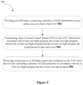
- FIG. 5 illustrates a block diagram of the method for omnidirectional light show 500 (hereinafter referred to as method 500), in accordance with an embodiment of the present disclosure.
- method 500 The order in which the method 500 is described is not intended to be construed as a limitation, and any number of the described method blocks can be combined in any order to implement the method or similar alternative methods. Additionally, individual blocks can be deleted from the method without departing from the spirit and scope of the subject matter described herein. Furthermore, the method can be implemented in any suitable hardware, software, firmware, or combination thereof.
- the method 500 includes the step of providing an LED matrix 104 comprising a plurality of LEDs 104A distributed on the outer surface area of a body 102A of the UAV 102.
- the plurality of LEDs 104A are provided on one or more portions of the outer surface area of the body 102A of the UAV. More specifically, in one embodiment, the LEDs 104A are provided on top and bottom outer surfaces of the UAV body, wherein the body has a rectangular cross section. In another embodiment, the LEDs 104A are provided on all faces of the rectangular body 102A of the UAV 102. In another embodiment, the body has a spherical or elliptical configuration, and the LEDs 104A are configured in an equidistant configuration along an entire surface area of the body.
- the method 500 includes transmitting, from a Ground Control Station (GCS) 106 to the UAV 102, information associated with at least one flight program and at least one light program, wherein the at least one flight program and the at least one light program are synchronized in time and events.
- GCS Ground Control Station
- the method 500 includes receiving instructions at a LED light control unit 108 configured on the UAV 102 from the GCS 106 for controlling a plurality of LED parameters in accordance with the at least one flight program and the at least one light program.
- the plurality of LED parameters includes direction of glow of the plurality of LEDs, intensity of the plurality of LEDs, ON/OFF signals for the plurality of LEDs, and switching mode for the plurality of LEDs.
- the intensity and direction of glow of the plurality of LEDs 104A is controlled based on a time stamp of an event, geolocation of the UAVs 102 with respect to a position of the observer, and external weather conditions.
- the direction of glow and intensity of the plurality of LEDs 104A is controlled based on the geolocation of the UAVs 102 with respect to a varying position of the observer, wherein the data associated with the varying position of the observer is fed to the LED light control unit 102 by the GCS 106 in real time.
- the GCS 106 sends control signals to the UAVs 102 to activate the UAVs 102, and after the activation of the UAVs 102, information associated with the light program and flight program are transmitted to the UAVs 102.
- the activation of the UAVs 102 is indicated by flickering of one LED on the UAV for indicating the readiness of the UAVs 102 to take off a flight in accordance with the selected flight program.
- the flight of the UAVs 102 is accompanied by flickering of a red LED on the top and bottom surfaces of the UAV 102 during takeoff. Such a red indication is to make the relevant observers aware of the position of the UAVs 102, in accordance with one implementation.
- Such indications of the UAV 102 are performed by the LED light control unit 108, in accordance with one embodiment of the present disclosure.
- the LED light control unit 108 is configured to turn off all the indications once the UAVs 102 reach the starting point where the light show is conducted.
- the GCS 106 is configured to track the geopositions of the UAVs 102, and once the geoposition of the UAVs 102 reaches or coincides with the geoposition of the starting point for the light show, the indicator lights of the UAVs 102 are turned off by the LED light control unit 108.
- the indication lights are turned off.
- the turning off the indication lights can be momentary, in accordance with one implementation.
- the turning off the indication lights itself is an indicator that the light show is about to begin.
- the LEDs 104A of the UAV 102 are turned on by the LED light control unit 108 and controlled in accordance with the light program.
- the starting point of the light show is typically selected or computed based on the location/position of the observer.
- the present system and corresponding method can be used to display a light show to any observer irrespective of the height at which the observer is located following the omni directionality provided by the plurality LEDs 104A distributed about the entire body of the UAVs 102. More specifically, to the observer located below the height of the UAVs 102, the LEDs 104A provided on the bottom surface may be activated according to the light program to display the light shows to the observers positioned below.
- the LEDs 104A provided on the top of the UAV body may be activated for displaying the required light show to the observer in accordance with the light program.
- the LEDs 104A are operated in accordance with the light program in which different tasks of the LEDs 104A are performed synchronously with the corresponding flight tasks of the UAV 102 in accordance with the flight program.
- This phenomenon is that brightness of the LEDs 104A may be made high at the beginning of the light show when the UAVs 102 are at a greater distance from the observer. Therefore, when the light program and flight program are in synchrony, this brightness can be reduced as the distance between the observer and the UAVs 102 is reduced.
- the real time tracking of the geopositions of the UAVs 102 and the observer is required.
- the GCS 106 is configured to perform or facilitate such real time tracking by communicating with the UAVs 102.
- Another exemplary application of synchrony in light program and flight program is to control the direction of the glow of the LEDs 104A. More specifically, the direction of glow of the LEDs 104A is controlled by switching on those LEDs 104A on the UAV 102 that are directly facing the observer.
- the LED light control unit 108 is configured to identify the LEDs 104A directly facing the observer based on the positions of the observer relative to the geoposition of the UAVs 102. The geopositions of the UAVs 102 is dependent on the flight program, whereas the selection of a group of LEDs 104A for activation to control the glow direction of the LEDs 104A is performed by the LED light control unit 108 based on the light program.
- the LED light control unit 108 is further configured to change in the brightness of the LEDs 104A depending on environmental factors. More specifically, the LEDs 104A are configured to shine more brightly in bad weather conditions such as in fog.
- the LED light control unit 108 is further configured to control the LEDs 104A based on the battery charge of the UAV 102. More specifically, if it is sensed that the battery is low, the brightness of the LEDs 104A can be systematically and gradually reduced for prolonging the light show.
- the UAVs 102 are configured to land in accordance with the flight program.
- the advantageous aspect of the system and method for displaying an omnidirectional light show is that no matter at what height the observer is positioned, the same system and method can be used to optimally present a light show to the observer using the plurality of UAVs at different heights, wherein the observer can be located at a height greater than the UAVs, or at a height equal to that of UAVs, or at a height less than that of the UAVs.
- the usage of the GCS facilitates real time monitoring of the geopositions of the UAVs, the positions of the observers, and accordingly control the operation of the LEDs 104A to control the direction of glow, intensity, and activation/deactivation of the LEDs.
Landscapes
- Engineering & Computer Science (AREA)
- Aviation & Aerospace Engineering (AREA)
- Illuminated Signs And Luminous Advertising (AREA)
Abstract
A system and a method for displaying a light show is disclosed herein. The system comprises a plurality of Unmanned Aerial Vehicles (UAVs) each having a a LED matrix comprising a plurality of LEDs attached thereto. A Ground Control Station (GCS) is communicatively coupled to the plurality of UAVs, wherein the communication between the GCS and the plurality of UAVs is bidirectional communication, and wherein the GCS is configured to control the plurality of UAVs in accordance with at least one flight program. A light controller is communicatively coupled to the GCS and configured to control at a plurality of LED parameters of the LEDs in accordance with the at least one flight program.
Description
- 1. The invention pertains to the field of unmanned aerial vehicles, and in particular the invention pertains to a system and method for displaying an omnidirectional light show using unmanned aerial vehicles.
- 2. Unmanned Aerial Vehicles (UAVs) are typically provided with light sources such as light-emitting diodes (LEDs) for providing indications when flying in poor lighting conditions such as at night or in weather conditions that cause poor visibility, as per the requirements of standards and requirements for aircrafts. Typically, these light sources are provided to indicate or enhance visibility of the UAV for observers at ground level or at a height greater than that at which the UAV is flying, e.g., observers traveling in planes or helicopters or those located on highrise buildings. While the LEDs mentioned above are equipped to provide indications in poor visibility, these LEDs and the UAVs are not equipped for special applications, such as light shows and geolocation indication for large aircrafts, including aircraft, satellites, helicopters and others. One reason for this is that such applications require controlling the direction and brightness of the light flux from the light sources on the UAVs with minimal power consumption for long-term and long-range flight missions.
- 3. As such, there is a need for a system that provides light indication in multiple directions with sufficient brightness for providing contrast perception over long distances and in various weather conditions.
- 4. The present disclosure describes a system for displaying an omnidirectional light show for an unmanned aerial vehicle (UAV). The system comprises an LED matrix comprising a plurality of LEDs distributed on the outer surface area of a body of the UAV A Ground Control Station (GCS) is communicatively coupled to the UAV and is configured to transmit at least one flight program and at least one light program, wherein the at least one flight program and the at least one light program are synchronized in time and events. A LED light control unit is configured on the UAV and is communicatively coupled to the GCS for receiving instructions from the GCS to control a plurality of LED parameters in accordance with the at least one flight program and the at least one light program.
- 5. In an alternative embodiment, the distribution of the plurality of LEDs on the outer surface area includes distribution on at least a portion of the outer surface area and distribution along a complete outer surface area.
- 6. In an alternative embodiment, the plurality of LED parameters includes direction of glow of the plurality of LEDs, intensity of the plurality of LEDs, ON/OFF signals for the plurality of LEDs, and switching mode for the plurality of LEDs.
- 7. In an alternative embodiment, the LED light control unit is at least one of a standalone controller, an expansion board, and a set of instructions.
- 8. In an alternative embodiment, the system further comprises at least one optical device for controlling an optical rendering from the plurality of LEDs.
- 9. In an alternative embodiment, the intensity of the plurality of LEDs is controlled based on a time stamp of an event, geolocation of the UAVs with respect to a position of the observer, and external weather conditions.
- 10. In an alternative embodiment, the intensity of the plurality of LEDs is controlled based on the geolocation of the UAVs with respect to a varying position of the observer, wherein the data associated with the varying position of the observer is fed to the LED light control unit by the GCS in real time.
- 11. In an alternative embodiment, the direction of glow of the plurality of LEDs is controlled based on a time stamp of an event and geolocation of the UAVs with respect to a position of the observer.
- 12. In an alternative embodiment, the direction of glow of the plurality of LEDs is controlled based on the geolocation of the UAVs with respect to a varying position of the observer, wherein the data associated with the varying position of the observer is fed to the LED light control unit by the GCS in real time.
- 13. In an alternative embodiment, different LEDs of the LED matrix having the same intensity are configured to be oriented in the same direction.
- 14. In an alternative embodiment, the LED matrix includes an integrated LED matrix controller.
- 15. The present disclosure also envisages a method for displaying an omnidirectional light show for an unmanned aerial vehicle (UAV). The method comprises providing an LED matrix comprising a plurality of LEDs distributed on outer surface area of a body of the UAV; transmitting, from a Ground Control Station (GCS) to the UAV, information associated with at least one flight program and at least one light program, wherein the at least one flight program and the at least one light program are synchronized in time and events; and receiving instructions at a LED light control unit configured on the UAV from the GCS for controlling a plurality of LED parameters in accordance with the at least one flight program and the at least one light program.
- 16. In an alternative embodiment, the distribution of the plurality of LEDs on the outer surface area includes distribution on at least a portion of the outer surface area and distribution along a complete outer surface area.
- 17. In an alternative embodiment, the plurality of LED parameters includes direction of glow of the plurality of LEDs, intensity of the plurality of LEDs, ON/OFF signals for the plurality of LEDs, and switching mode for the plurality of LEDs.
- 18. In an alternative embodiment, the LED light control unit is at least one of a standalone controller, an expansion board, and a set of instructions.
- 19. In an alternative embodiment, the method further comprises providing at least one optical device on the UAV for controlling an optical rendering from the plurality of LEDs.
- 20. In an alternative embodiment, the intensity of the plurality of LEDs is controlled based on a time stamp of an event, geolocation of the UAVs with respect to a position of the observer, and external weather conditions.
- 21. In an alternative embodiment, the intensity of the plurality of LEDs is controlled based on the geolocation of the UAVs with respect to a varying position of the observer, wherein the data associated with the varying position of the observer is fed to the LED light control unit by the GCS in real time.
- 22. In an alternative embodiment, the direction of glow of the plurality of LEDs is controlled based on a time stamp of an event and geolocation of the UAVs with respect to a position of the observer.
- 23. In an alternative embodiment, the direction of glow of the plurality of LEDs is controlled based on the geolocation of the UAVs with respect to a varying position of the observer, wherein the data associated with the varying position of the observer is fed to the LED light control unit by the GCS in real time.
-
- 24.
Figure 1 illustrates a schematic view of a system for omnidirectional light show, in accordance with an embodiment of the present disclosure. - 25.
Figure 2 illustrates a schematic view of an unmanned aerial vehicle (UAV) used in the system, in accordance with an embodiment of the present disclosure. - 26.
Figure 3 illustrates another schematic view of an unmanned aerial vehicle (UAV) used in the system, in accordance with an embodiment of the present disclosure. - 27.
Figure 4 illustrates a block diagram of the system for omnidirectional light show, in accordance with an embodiment of the present disclosure. - 28.
Figure 5 illustrates a block diagram of the method for omnidirectional light show, in accordance with an embodiment of the present disclosure. - 29.
Figure 1 illustrates a schematic view of a system for omnidirectional light show (hereinafter referred to as system 100) for an Unmanned Aerial Vehicle (UAV) 102, in accordance with an embodiment of the present disclosure. In accordance with an embodiment of the present subject matter, the system 100 employs a plurality ofUAVs 102 for conducting the omnidirectional light show. TheUAVs 102, in accordance with the present disclosure, are designed with multiple light sources to ensure that the light flux from the UAV can be directed in multiple directions to ensure the omnidirectionality of the present system 100. The schematic exemplary construction of theUAV 102, in accordance with the present disclosure, is described in the subsequent sections of the present disclosure. As seen inFigure 1 , the system 100 is configured to provide a light show or geolocation indication to observers at multiple different locations such as at ground level, or on a highrise building, or a helicopter or plane traveling at a height greater than that of the light show. More specifically, the system 100 is configured to arrange theUAVs 102 in accordance with the observer position to best display the light show or geolocation indication to the required observer (humans at ground level or on high buildings or other aircrafts) no matter at what height they are located. - 30. In one embodiment, the system 100 comprises an
LED matrix 104 comprising a plurality ofLEDs 104A distributed on outer surface area of abody 102A of the UAV 102 (as seen inFigure 2). Figure 2 illustrates a schematic view of the unmanned aerial vehicle (UAV) 102 used in the system, in accordance with an embodiment of the present disclosure. In an embodiment, as seen inFigure 2 , wherein thebody 102A has a rectangular cross section, the plurality of LEDs 104Aare distributed along the top and bottom faces thereof. These LEDs allow theUAVs 102 to provide a light show to observers that are above the height of theUAV 102 as well as to those observers that are below the height of theUAV 102. In some embodiments, theLEDs 104A are provided on all the faces of such a body. In another embodiment, wherein the body has a spherical or an elliptical configuration, theLEDs 104A are distributed in an equidistant manner along the entire surface area thereof. In one embodiment, it is envisaged that theLEDs 104A are provided on a partial surface area of the body of the UAV. In another embodiment, it is envisaged that theLEDs 104A are provided on a complete surface area of the body of the UAV - 31. The system 100 further comprises a Ground Control Station (GCS) 106 that is communicatively coupled to the
UAV 102 and is configured to transmit at least one flight program and at least one light program, wherein the at least one flight program and the at least one light program are synchronized in time and events. The flight program is configured to control the flight of theUAVs 102 for ensuring that theUAVs 102 are arranged to fly appropriately depending on the position of the observer. The light program is synchronized in time and events with the flight program, and therefore, the light program dictates the operation of theLEDs 104A on theUAVs 102 for presenting the light show. - 32. The system 100 further comprises a LED
light control unit 108 that is configured on theUAV 102 and is communicatively coupled to theGCS 106 for receiving instructions from the GCS to control a plurality of LED parameters in accordance with the at least one flight program and the at least one light program. In an embodiment, the plurality of LED parameters includes direction of glow of the plurality ofLEDs 104A, intensity of the plurality ofLEDs 104A, ON/OFF signals for the plurality ofLEDs 104A and switching mode for the plurality of LEDs (flickering, constant glow, blinking, gradient change in the color of the glow). In one embodiment, the LEDlight control unit 108 is at least one of a standalone controller, an expansion board, and a set of instructions (executable on a controller). - 33. In one embodiment, the LED
light control unit 108 controls the operation of theLEDs 104A according to the selected light program. For example, theLED control unit 108 is configured to switch on theLEDs 104A depending on the timestamp of the flight program or geolocation of theUAVs 102. In one embodiment, the LEDlight control unit 108 is configured to change the brightness or intensity of theLEDs 104A depending on external weather factors; change the brightness depending on the distance to the observer (airplane, helicopter, floor of a skyscraper). In one embodiment, the LEDlight control unit 108 is configured to change the direction of glow of theLEDs 104A to direct the glow depending on the point of the observer (for example, tracking the geoposition of a helicopter approaching a group of drones or glowing towards a stationary observer when a group of drones move in space). In one embodiment, the LEDlight control unit 108 is configured to change the brightness depending on the illumination; change the brightness and colors depending on the timestamp of the flight program. In one embodiment, the LEDlight control unit 108 is configured to switch modes depending on the time stamp or geolocation of the drone (flickering, constant glow, blinking, gradient change in the color of the glow). - 34. In an embodiment, the intensity and direction of glow of the plurality of
LEDs 104 is controlled by theLED control unit 108 based on a time stamp of an event, geolocation of the UAVs with respect to a position of the observer, and external weather conditions. In an embodiment, the position of the observer may be varying, e.g., in case of displaying geolocations to aircrafts. In such a scenario, the data associated with the varying position of the observer is fed to the LEDlight control unit 108 by theGCS 106 in real time, which allows the LEDlight control unit 108 to control the intensity and direction of glow of theLEDs 104A to ensure that the moving observer has the best possible view of the required indication or light show. In yet another embodiment,different LEDs 104A of theLED matrix 104 having the same intensity are configured to be oriented in the same direction. - 35.
Figure 3 illustrates another schematic view of the unmanned aerial vehicle (UAV) 102 used in the system, in accordance with an embodiment of the present disclosure. As seen inFigure 3 , the system 100 further comprises at least oneoptical device 110 for controlling an optical rendering from the plurality ofLEDs 104A. More specifically, theoptical device 110 is a diffuser in one exemplary embodiment. The diffuser facilitates the diffusion of light fluxes fromseveral LEDs 104A and forms a single light flux from theUAV 102, rather than several single streams from eachLED 104A on theUAV 102. In another embodiment, theoptical device 110 can be a lens or a combination of multiple lenses or a combination of lenses and diffusers, wherein such a configuration of the optical devices is employed for facilitating desired optical rendering of light from theLEDs 104A according to the selected light program. - 36.
Figure 4 illustrates a block diagram of the system 100, in accordance with an embodiment of the present disclosure. As seen inFigure 4 , theflight program module 402 and thelight program module 404 are configured at theGCS 106. The user can select the desired flight program and light program at theGCS 106, wherein the flight program and the light program are synchronized in time and events. The system 100 includesUAVs 102. EachUAV 102 includes a controller 406. The system 100 further comprises the LEDlight control unit 108. In one embodiment, the LEDlight control unit 108 is a set of instructions executable by the controller 406. As mentioned previously, the LEDlight control unit 108 is configured to control theLED matrix 104 to control a plurality of LED parameters including direction of glow of the plurality ofLEDs 104A, intensity of the plurality ofLEDs 104A, ON/OFF signals for the plurality ofLEDs 104A and switching mode for the plurality of LEDs (flickering, constant glow, blinking, gradient change in the color of the glow). In an embodiment, theLED matrix 104 includes an integrated LED matrix controller to control theLED matrix 104 through one physical communication channel, or eachLED 104A can be connected to a separate control pin (separate communication channel). In the former scenario, a digital signal is applied to theLED matrix 104 encoding the glow level and light for eachaddressable LED 104A, whereas in the latter scenario, it can be done either via a digital or an analog control signal. - 37.
Figure 5 illustrates a block diagram of the method for omnidirectional light show 500 (hereinafter referred to as method 500), in accordance with an embodiment of the present disclosure. The order in which themethod 500 is described is not intended to be construed as a limitation, and any number of the described method blocks can be combined in any order to implement the method or similar alternative methods. Additionally, individual blocks can be deleted from the method without departing from the spirit and scope of the subject matter described herein. Furthermore, the method can be implemented in any suitable hardware, software, firmware, or combination thereof. - 38. At
block 502, themethod 500 includes the step of providing anLED matrix 104 comprising a plurality ofLEDs 104A distributed on the outer surface area of abody 102A of theUAV 102. In one embodiment, the plurality ofLEDs 104A are provided on one or more portions of the outer surface area of thebody 102A of the UAV. More specifically, in one embodiment, theLEDs 104A are provided on top and bottom outer surfaces of the UAV body, wherein the body has a rectangular cross section. In another embodiment, theLEDs 104A are provided on all faces of therectangular body 102A of theUAV 102. In another embodiment, the body has a spherical or elliptical configuration, and theLEDs 104A are configured in an equidistant configuration along an entire surface area of the body. - 39. At
block 504, themethod 500 includes transmitting, from a Ground Control Station (GCS) 106 to theUAV 102, information associated with at least one flight program and at least one light program, wherein the at least one flight program and the at least one light program are synchronized in time and events. - 40. At block 506, the
method 500 includes receiving instructions at a LEDlight control unit 108 configured on theUAV 102 from theGCS 106 for controlling a plurality of LED parameters in accordance with the at least one flight program and the at least one light program. In an embodiment, the plurality of LED parameters includes direction of glow of the plurality of LEDs, intensity of the plurality of LEDs, ON/OFF signals for the plurality of LEDs, and switching mode for the plurality of LEDs. - 41. In an alternative embodiment, the intensity and direction of glow of the plurality of
LEDs 104A is controlled based on a time stamp of an event, geolocation of theUAVs 102 with respect to a position of the observer, and external weather conditions. In an alternative embodiment, the direction of glow and intensity of the plurality ofLEDs 104A is controlled based on the geolocation of theUAVs 102 with respect to a varying position of the observer, wherein the data associated with the varying position of the observer is fed to the LEDlight control unit 102 by theGCS 106 in real time. - 42. Atypical operation of the system 100 in accordance with the
method 500 is described herein. In one embodiment, theGCS 106 sends control signals to theUAVs 102 to activate theUAVs 102, and after the activation of theUAVs 102, information associated with the light program and flight program are transmitted to theUAVs 102. In one embodiment, the activation of theUAVs 102 is indicated by flickering of one LED on the UAV for indicating the readiness of theUAVs 102 to take off a flight in accordance with the selected flight program. In another embodiment, the flight of theUAVs 102 is accompanied by flickering of a red LED on the top and bottom surfaces of theUAV 102 during takeoff. Such a red indication is to make the relevant observers aware of the position of theUAVs 102, in accordance with one implementation. Such indications of theUAV 102 are performed by the LEDlight control unit 108, in accordance with one embodiment of the present disclosure. - 43. In accordance with the instant implementation, the LED
light control unit 108 is configured to turn off all the indications once theUAVs 102 reach the starting point where the light show is conducted. TheGCS 106 is configured to track the geopositions of theUAVs 102, and once the geoposition of theUAVs 102 reaches or coincides with the geoposition of the starting point for the light show, the indicator lights of theUAVs 102 are turned off by the LEDlight control unit 108. - 44. After reaching the starting point of the light show, the indication lights are turned off. The turning off the indication lights can be momentary, in accordance with one implementation. The turning off the indication lights itself is an indicator that the light show is about to begin. As such, at this stage the
LEDs 104A of theUAV 102 are turned on by the LEDlight control unit 108 and controlled in accordance with the light program. It is to be noted that the starting point of the light show is typically selected or computed based on the location/position of the observer. - 45. As mentioned previously, the present system and corresponding method can be used to display a light show to any observer irrespective of the height at which the observer is located following the omni directionality provided by the
plurality LEDs 104A distributed about the entire body of theUAVs 102. More specifically, to the observer located below the height of theUAVs 102, theLEDs 104A provided on the bottom surface may be activated according to the light program to display the light shows to the observers positioned below. Similarly, if the observers are located at a location above the height of theUAVs 102, e.g., on a highrise building or aircrafts needing geoposition indications, theLEDs 104A provided on the top of the UAV body may be activated for displaying the required light show to the observer in accordance with the light program. - 46. After the light show is initiated, the
LEDs 104A are operated in accordance with the light program in which different tasks of theLEDs 104A are performed synchronously with the corresponding flight tasks of theUAV 102 in accordance with the flight program. One example of this phenomenon is that brightness of theLEDs 104A may be made high at the beginning of the light show when theUAVs 102 are at a greater distance from the observer. Therefore, when the light program and flight program are in synchrony, this brightness can be reduced as the distance between the observer and theUAVs 102 is reduced. For such synchronization, the real time tracking of the geopositions of theUAVs 102 and the observer is required. In one embodiment, theGCS 106 is configured to perform or facilitate such real time tracking by communicating with theUAVs 102. - 47. Another exemplary application of synchrony in light program and flight program is to control the direction of the glow of the
LEDs 104A. More specifically, the direction of glow of theLEDs 104A is controlled by switching on thoseLEDs 104A on theUAV 102 that are directly facing the observer. The LEDlight control unit 108 is configured to identify theLEDs 104A directly facing the observer based on the positions of the observer relative to the geoposition of theUAVs 102. The geopositions of theUAVs 102 is dependent on the flight program, whereas the selection of a group ofLEDs 104A for activation to control the glow direction of theLEDs 104A is performed by the LEDlight control unit 108 based on the light program. - 48. Also, the LED
light control unit 108 is further configured to change in the brightness of theLEDs 104A depending on environmental factors. More specifically, theLEDs 104A are configured to shine more brightly in bad weather conditions such as in fog. The LEDlight control unit 108 is further configured to control theLEDs 104A based on the battery charge of theUAV 102. More specifically, if it is sensed that the battery is low, the brightness of theLEDs 104A can be systematically and gradually reduced for prolonging the light show. - 49. After the light show in accordance with the light program is concluded, the
UAVs 102 are configured to land in accordance with the flight program. - 50. The advantageous aspect of the system and method for displaying an omnidirectional light show, in accordance with an embodiment of the present disclosure, is that no matter at what height the observer is positioned, the same system and method can be used to optimally present a light show to the observer using the plurality of UAVs at different heights, wherein the observer can be located at a height greater than the UAVs, or at a height equal to that of UAVs, or at a height less than that of the UAVs. Furthermore, the usage of the GCS facilitates real time monitoring of the geopositions of the UAVs, the positions of the observers, and accordingly control the operation of the
LEDs 104A to control the direction of glow, intensity, and activation/deactivation of the LEDs.
Claims (20)
- A system for displaying an omnidirectional light show for an unmanned aerial vehicle (UAV), the system comprising:a. an LED matrix comprising a plurality of LEDs distributed on outer surface area of a body of the UAV;b. a Ground Control Station (GCS) communicatively coupled to the UAV, wherein the GCS is configured to transmit at least one flight program and at least one light program, wherein the at least one flight program and the at least one light program are synchronized in time and events; andc. a LED light control unit configured on the UAV, the LED light control unit communicatively coupled to the GCS for receiving instructions from the GCS to control a plurality of LED parameters in accordance with the at least one flight program and the at least one light program.
- The system of claim 1, wherein the distribution of the plurality of LEDs on the outer surface area includes distribution on at least a portion of the outer surface area and distribution along a complete outer surface area.
- The system of claim 1, wherein the plurality of LED parameters includes direction of glow of the plurality of LEDs, intensity of the plurality of LEDs, ON/OFF signals for the plurality of LEDs, and switching mode for the plurality of LEDs.
- The system of claim 1, wherein the LED light control unit is at least one of a standalone controller, an expansion board, and a set of instructions.
- The system of claim 1, further comprising at least one optical device for controlling an optical rendering from the plurality of LEDs.
- The system of claim 3, wherein the intensity of the plurality of LEDs is controlled based on a time stamp of an event, geolocation of the UAVs with respect to a position of the observer, and external weather conditions.
- The system of claim 3, wherein the intensity of the plurality of LEDs is controlled based on the geolocation of the UAVs with respect to a varying position of the observer, wherein the data associated with the varying position of the observer is fed to the LED light control unit by the GCS in real time.
- The system of claim 3, wherein the direction of glow of the plurality of LEDs is controlled based on a time stamp of an event and geolocation of the UAVs with respect to a position of the observer.
- The system of claim 3, wherein the direction of glow of the plurality of LEDs is controlled based on the geolocation of the UAVs with respect to a varying position of the observer, wherein the data associated with the varying position of the observer is fed to the LED light control unit by the GCS in real time.
- The system of claim 3, wherein different LEDs of the LED matrix having same intensity are configured to be oriented in the same direction.
- The system of claim 1, wherein the LED matrix includes an integrated LED matrix controller.
- A method for displaying an omnidirectional light show for an unmanned aerial vehicle (UAV), the method comprising:a. providing an LED matrix comprising a plurality of LEDs distributed on outer surface area of a body of the UAV;b. transmitting, from a Ground Control Station (GCS) to the UAV, information associated with at least one flight program and at least one light program, wherein the at least one flight program and the at least one light program are synchronized in time and events; andc. receiving instructions at a LED light control unit configured on the UAV from the GCS for controlling a plurality of LED parameters in accordance with the at least one flight program and the at least one light program.
- The method of claim 12, wherein the distribution of the plurality of LEDs on the outer surface area includes distribution on at least a portion of the outer surface area and distribution along a complete outer surface area.
- The method of claim 12, wherein the plurality of LED parameters includes direction of glow of the plurality of LEDs, intensity of the plurality of LEDs, ON/OFF signals for the plurality of LEDs, and switching mode for the plurality of LEDs.
- The method of claim 12, wherein the LED light control unit is at least one of a standalone controller, an expansion board, and a set of instructions.
- The method of claim 12, further comprising providing at least one optical device on the UAV for controlling an optical rendering from the plurality of LEDs.
- The method of claim 14, wherein the intensity of the plurality of LEDs is controlled based on a time stamp of an event, geolocation of the UAVs with respect to a position of the observer, and external weather conditions.
- The method of claim 14, wherein the intensity of the plurality of LEDs is controlled based on the geolocation of the UAVs with respect to a varying position of the observer, wherein the data associated with the varying position of the observer is fed to the LED light control unit by the GCS in real time.
- The method of claim 14, wherein the direction of glow of the plurality of LEDs is controlled based on a time stamp of an event and geolocation of the UAVs with respect to a position of the observer.
- The method of claim 14, wherein the direction of glow of the plurality of LEDs is controlled based on the geolocation of the UAVs with respect to a varying position of the observer, wherein the data associated with the varying position of the observer is fed to the LED light control unit by the GCS in real time.
Applications Claiming Priority (1)
| Application Number | Priority Date | Filing Date | Title |
|---|---|---|---|
| US17/663,838 US11905034B2 (en) | 2022-05-18 | 2022-05-18 | Omnidirectional light drone show |
Publications (1)
| Publication Number | Publication Date |
|---|---|
| EP4280822A1 true EP4280822A1 (en) | 2023-11-22 |
Family
ID=84389361
Family Applications (1)
| Application Number | Title | Priority Date | Filing Date |
|---|---|---|---|
| EP22020585.0A Pending EP4280822A1 (en) | 2022-05-18 | 2022-11-30 | Omnidirectional light drone show |
Country Status (2)
| Country | Link |
|---|---|
| US (1) | US11905034B2 (en) |
| EP (1) | EP4280822A1 (en) |
Citations (1)
| Publication number | Priority date | Publication date | Assignee | Title |
|---|---|---|---|---|
| US20190315486A1 (en) * | 2018-04-16 | 2019-10-17 | Qualcomm Incorporated | Adaptive Voxels for Aerial Light Shows |
Family Cites Families (10)
| Publication number | Priority date | Publication date | Assignee | Title |
|---|---|---|---|---|
| US8454212B2 (en) * | 2007-12-28 | 2013-06-04 | Sirio Panel S.P.A. | Anti-collision light for aircraft |
| WO2018058297A1 (en) | 2016-09-27 | 2018-04-05 | 深圳市大疆创新科技有限公司 | Navigation lamp of unmanned aerial vehicle and unmanned aerial vehicle |
| US10602591B2 (en) * | 2017-08-29 | 2020-03-24 | Abl Ip Holding Llc | Mechatronic transforming luminaire swarm |
| CN110641715A (en) | 2019-09-17 | 2020-01-03 | 天津大学 | Many unmanned aerial vehicle charge parking apron district guide descending management system |
| US20210341128A1 (en) | 2021-04-25 | 2021-11-04 | Teresa Elaine Byrd | Control Drone Lighting Device |
| CN215753057U (en) | 2021-06-08 | 2022-02-08 | 常州希米智能科技有限公司 | Rotor unmanned aerial vehicle gathers image and uses automatic light filling device |
| CN113917944A (en) | 2021-10-19 | 2022-01-11 | 西安理工大学 | Wireless ultraviolet light cooperation cluster unmanned aerial vehicle enclosure method |
| CN114326782A (en) | 2021-11-23 | 2022-04-12 | 衢州光明电力投资集团有限公司赋腾科技分公司 | Unmanned aerial vehicle swarm formation method based on wireless laser communication technology |
| CN116198737B (en) | 2021-11-28 | 2025-11-07 | 中船海为高科技有限公司 | Automatic collection system of temporary airport emergency navigation light unmanned aerial vehicle |
| CN218641076U (en) | 2022-10-13 | 2023-03-17 | 深圳化骨龙科技有限公司 | Lightweight spherical unmanned aerial vehicle |
-
2022
- 2022-05-18 US US17/663,838 patent/US11905034B2/en active Active
- 2022-11-30 EP EP22020585.0A patent/EP4280822A1/en active Pending
Patent Citations (1)
| Publication number | Priority date | Publication date | Assignee | Title |
|---|---|---|---|---|
| US20190315486A1 (en) * | 2018-04-16 | 2019-10-17 | Qualcomm Incorporated | Adaptive Voxels for Aerial Light Shows |
Also Published As
| Publication number | Publication date |
|---|---|
| US11905034B2 (en) | 2024-02-20 |
| US20230373655A1 (en) | 2023-11-23 |
Similar Documents
| Publication | Publication Date | Title |
|---|---|---|
| ES2333145T3 (en) | PROGRAMMABLE IMPROVEMENT SYSTEM FOR THE CABIN OF A PILOT. | |
| US8297776B2 (en) | “Lip light” automatically controlled by the position of the head | |
| EP2459963B1 (en) | Aircraft avionics system | |
| EP3798120B1 (en) | Retention of flight deck preferences | |
| JP6525145B2 (en) | Emitting point figure pattern display system using a flying object, a method of displaying a light emitting point figure pattern, and a flying object used for the system and method | |
| RU2520174C2 (en) | Helicopter onboard hardware complex | |
| US11036453B1 (en) | Bezel embedded head tracking fiducials | |
| US20190248511A1 (en) | Helicopter and VTOL Aircraft Landing Pad Information Sheet | |
| US4868567A (en) | Landing approach aid for aircraft | |
| WO2015073540A1 (en) | Lighting systems for aircraft operation in a degraded visual environment | |
| US5793164A (en) | Low intensity aircraft rotor tip illumination | |
| EP3778391B1 (en) | Method of emitting an anti-collision light output from an unmanned aerial vehicle, anti-collision light for an unmanned aerial vehicle, and unmanned aerial vehicle comprising the same | |
| US11905034B2 (en) | Omnidirectional light drone show | |
| US20220335843A1 (en) | Distribution device, aircraft, flight system, method for these, and non-transitory computer readable medium | |
| US7679528B1 (en) | Modulation of aircraft guidance lights | |
| US10511762B2 (en) | System and method for aircraft camera image alignment | |
| EP3112265B1 (en) | Dual-mode formation-light system | |
| EP3335997B1 (en) | Method of operating an aircraft headlight system, aircraft headlight system, and aircraft comprising the same | |
| JP2020095563A (en) | Unmanned aerial vehicle system | |
| CN208337958U (en) | A kind of helistop lighting system | |
| RU2671926C1 (en) | Glide path fire system providing visual and optical night time landing of helicopter to ship in night vision goggles | |
| US6505119B2 (en) | Control unit and mission planning station for a manned paragliding system | |
| JP2001126200A (en) | Airfield light monitoring and control device | |
| Naumann et al. | Distributed aperture system field of view investigation | |
| RU2300486C1 (en) | Flying vehicle landing support system |
Legal Events
| Date | Code | Title | Description |
|---|---|---|---|
| PUAI | Public reference made under article 153(3) epc to a published international application that has entered the european phase |
Free format text: ORIGINAL CODE: 0009012 |
|
| STAA | Information on the status of an ep patent application or granted ep patent |
Free format text: STATUS: REQUEST FOR EXAMINATION WAS MADE |
|
| 17P | Request for examination filed |
Effective date: 20221201 |
|
| AK | Designated contracting states |
Kind code of ref document: A1 Designated state(s): AL AT BE BG CH CY CZ DE DK EE ES FI FR GB GR HR HU IE IS IT LI LT LU LV MC ME MK MT NL NO PL PT RO RS SE SI SK SM TR |
|
| STAA | Information on the status of an ep patent application or granted ep patent |
Free format text: STATUS: EXAMINATION IS IN PROGRESS |
|
| 17Q | First examination report despatched |
Effective date: 20240923 |