EP4280656A1 - Strahlwiederherstellungsverfahren für multi-trp-system, kommunikationsvorrichtung und lesbares speichermedium - Google Patents
Strahlwiederherstellungsverfahren für multi-trp-system, kommunikationsvorrichtung und lesbares speichermedium Download PDFInfo
- Publication number
- EP4280656A1 EP4280656A1 EP21918677.2A EP21918677A EP4280656A1 EP 4280656 A1 EP4280656 A1 EP 4280656A1 EP 21918677 A EP21918677 A EP 21918677A EP 4280656 A1 EP4280656 A1 EP 4280656A1
- Authority
- EP
- European Patent Office
- Prior art keywords
- trp
- receiving
- failure event
- recovery method
- resource
- Prior art date
- Legal status (The legal status is an assumption and is not a legal conclusion. Google has not performed a legal analysis and makes no representation as to the accuracy of the status listed.)
- Pending
Links
- 238000000034 method Methods 0.000 title claims abstract description 125
- 238000011084 recovery Methods 0.000 title claims abstract description 106
- 230000006854 communication Effects 0.000 title claims description 54
- 238000004891 communication Methods 0.000 title claims description 52
- 230000005540 biological transmission Effects 0.000 claims abstract description 115
- 230000008569 process Effects 0.000 claims description 22
- 230000004044 response Effects 0.000 claims description 22
- 238000001514 detection method Methods 0.000 claims description 16
- 230000011664 signaling Effects 0.000 claims description 16
- 238000013507 mapping Methods 0.000 claims description 6
- 238000012544 monitoring process Methods 0.000 claims description 3
- 230000007246 mechanism Effects 0.000 description 20
- 238000010586 diagram Methods 0.000 description 13
- 230000003213 activating effect Effects 0.000 description 10
- LKKMLIBUAXYLOY-UHFFFAOYSA-N 3-Amino-1-methyl-5H-pyrido[4,3-b]indole Chemical compound N1C2=CC=CC=C2C2=C1C=C(N)N=C2C LKKMLIBUAXYLOY-UHFFFAOYSA-N 0.000 description 9
- 102100031413 L-dopachrome tautomerase Human genes 0.000 description 9
- 101710093778 L-dopachrome tautomerase Proteins 0.000 description 9
- 238000005259 measurement Methods 0.000 description 7
- 238000013461 design Methods 0.000 description 6
- 238000012545 processing Methods 0.000 description 6
- 238000005516 engineering process Methods 0.000 description 5
- 108010076504 Protein Sorting Signals Proteins 0.000 description 4
- 230000008878 coupling Effects 0.000 description 4
- 238000010168 coupling process Methods 0.000 description 4
- 238000005859 coupling reaction Methods 0.000 description 4
- 238000007726 management method Methods 0.000 description 4
- 230000009286 beneficial effect Effects 0.000 description 2
- 239000000835 fiber Substances 0.000 description 2
- 230000003287 optical effect Effects 0.000 description 2
- 230000000737 periodic effect Effects 0.000 description 2
- 230000001960 triggered effect Effects 0.000 description 2
- 101150069124 RAN1 gene Proteins 0.000 description 1
- 101100355633 Salmo salar ran gene Proteins 0.000 description 1
- 230000002776 aggregation Effects 0.000 description 1
- 238000004220 aggregation Methods 0.000 description 1
- 238000013459 approach Methods 0.000 description 1
- 230000001413 cellular effect Effects 0.000 description 1
- 125000004122 cyclic group Chemical group 0.000 description 1
- 230000009977 dual effect Effects 0.000 description 1
- 230000006870 function Effects 0.000 description 1
- 238000010295 mobile communication Methods 0.000 description 1
- 238000013468 resource allocation Methods 0.000 description 1
- 238000010187 selection method Methods 0.000 description 1
- 230000009466 transformation Effects 0.000 description 1
- 238000011144 upstream manufacturing Methods 0.000 description 1
Images


Classifications
-
- H—ELECTRICITY
- H04—ELECTRIC COMMUNICATION TECHNIQUE
- H04W—WIRELESS COMMUNICATION NETWORKS
- H04W24/00—Supervisory, monitoring or testing arrangements
- H04W24/04—Arrangements for maintaining operational condition
-
- H—ELECTRICITY
- H04—ELECTRIC COMMUNICATION TECHNIQUE
- H04B—TRANSMISSION
- H04B7/00—Radio transmission systems, i.e. using radiation field
- H04B7/02—Diversity systems; Multi-antenna system, i.e. transmission or reception using multiple antennas
- H04B7/04—Diversity systems; Multi-antenna system, i.e. transmission or reception using multiple antennas using two or more spaced independent antennas
- H04B7/06—Diversity systems; Multi-antenna system, i.e. transmission or reception using multiple antennas using two or more spaced independent antennas at the transmitting station
- H04B7/0686—Hybrid systems, i.e. switching and simultaneous transmission
- H04B7/0695—Hybrid systems, i.e. switching and simultaneous transmission using beam selection
- H04B7/06952—Selecting one or more beams from a plurality of beams, e.g. beam training, management or sweeping
- H04B7/06964—Re-selection of one or more beams after beam failure
-
- H—ELECTRICITY
- H04—ELECTRIC COMMUNICATION TECHNIQUE
- H04B—TRANSMISSION
- H04B7/00—Radio transmission systems, i.e. using radiation field
- H04B7/02—Diversity systems; Multi-antenna system, i.e. transmission or reception using multiple antennas
- H04B7/022—Site diversity; Macro-diversity
- H04B7/024—Co-operative use of antennas of several sites, e.g. in co-ordinated multipoint or co-operative multiple-input multiple-output [MIMO] systems
-
- H—ELECTRICITY
- H04—ELECTRIC COMMUNICATION TECHNIQUE
- H04L—TRANSMISSION OF DIGITAL INFORMATION, e.g. TELEGRAPHIC COMMUNICATION
- H04L5/00—Arrangements affording multiple use of the transmission path
- H04L5/003—Arrangements for allocating sub-channels of the transmission path
- H04L5/0032—Distributed allocation, i.e. involving a plurality of allocating devices, each making partial allocation
- H04L5/0035—Resource allocation in a cooperative multipoint environment
-
- H—ELECTRICITY
- H04—ELECTRIC COMMUNICATION TECHNIQUE
- H04L—TRANSMISSION OF DIGITAL INFORMATION, e.g. TELEGRAPHIC COMMUNICATION
- H04L5/00—Arrangements affording multiple use of the transmission path
- H04L5/003—Arrangements for allocating sub-channels of the transmission path
- H04L5/0053—Allocation of signalling, i.e. of overhead other than pilot signals
-
- H—ELECTRICITY
- H04—ELECTRIC COMMUNICATION TECHNIQUE
- H04W—WIRELESS COMMUNICATION NETWORKS
- H04W72/00—Local resource management
- H04W72/20—Control channels or signalling for resource management
- H04W72/23—Control channels or signalling for resource management in the downlink direction of a wireless link, i.e. towards a terminal
- H04W72/231—Control channels or signalling for resource management in the downlink direction of a wireless link, i.e. towards a terminal the control data signalling from the layers above the physical layer, e.g. RRC or MAC-CE signalling
Definitions
- the present application relates to the field of wireless communication, and in particular, to a beam recovery method, a communication device, and a readable storage medium for a multi-TRP system.
- Multiple beams can be configured at both the base station and the user equipment (UE: User Equipment) to cover a larger angle. If the transmit and receive beams between the base station and the UE are aligned, a greater link gain can be obtained.
- the process of aligning the transmission and reception beams of the base station and the UE is called a beam management process.
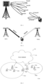
- the beam management process includes beam selection, beam measurement, beam reporting, beam indication and beam recovery. As shown in FIG. 1 , for a single transmission/reception point (TRP) system, it is assumed that the base station is configured with 4 beams and the UE is configured with 2 beams. After the beam management process, the beam #3 of the base station and the UE's beam # 1 can be selected for transmission reception.
- TRP transmission/reception point
- the beam recovery mechanism mainly includes beam failure detection, beam failure reporting, and beam recovery process.
- Downlink beam transmission failure is defined as the quality of each Physical Downlink Control Channel (PDCCH) beam monitored by the UE is lower than a specified threshold, so that the UE cannot effectively receive the control information sent by the PDCCH.
- the UE determines that the beam transmission failure event occurs, it reports the event to the base station and reports the new candidate beam information. According to the received report information, the base station recovers from the beam failure as soon as possible through the beam recovery process, and reselects a new beam for transmission to replace the original beam.
- PDCCH Physical Downlink Control Channel
- the master cell group (MCG) and the secondary cell group (SCG) are concepts under dual connectivity (DC). It can be understood that the group in which the cell where the UE initiates random access first is the MCG. Under the MCG, there may be many cells, one of which is used to initiate initial access, and this cell is called a primary cell (PCell). The PCell under the MCG and the secondary cell (SCell) under the MCG are combined via carrier aggregation (CA) technology. Similarly, there will also be a most important cell under the SCG, that is, the primary secondary cell (PSCell), which can also be understood as the cell that initiates the initial access under the SCG. PSCell under SCG and SCell under SCG are also combined through CA technology. In a New Radio (NR) system, many signalings are only sent on PCell and PSCell.
- NR New Radio
- a multi-TRP i.e.,: Multiple DCIs based Multiple TRPs
- DCI downlink control information
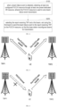
- two transmission and reception nodes TRP1 and TRP2 respectively schedule a user equipment
- these TRPs can perform independent scheduling on the UE, such as resource allocation or other control information.
- High-layer signaling can configure up to 5 control resource sets (CORESETs), and these CORESETs are divided into several groups, and the group identifier is used to indicate the TRP identifier.
- CORESETs control resource sets
- CORESET is divided into two groups according to the parameter CORESETPoolIndex under the high-level parameter ControlResourceSet, each group is marked with CORESETPoolIndex, and CORESETPoolIndex is used to distinguish different TRPs. That is, if CORESETPoolIndex is 0, this group CORESET is associated with the first TRP. If CORESETPoolIndex is 1, this group of CORESETs is associated with the second TRP.
- the UE can identify two different TRPs.
- a cell group supports at most one scheduling request dedicated (SR)-based PUCCH resources.
- SR scheduling request dedicated
- a cell group (Cell Group) supports at most two or more dedicated SR-based PUCCH resources.
- MAC CE medium access control layer control element carrying the beam failure recovery request (BFRQ)
- BFRQ beam failure recovery request
- the present application provides a beam recovery method in a multi-TRP system.
- the method is executed on the user equipment side, and includes:
- the step of selecting the report-receiving TRP and the first beam further includes: selecting a TRP in which the beam failure event occurs as the report-receiving TRP, and selecting a corresponding pointing beam of the report-receiving TRP as the first beam.
- the step of selecting the report-receiving TRP and the first beam further includes: selecting a TRP without a beam failure event as the report-receiving TRP, and selecting its corresponding pointing beam as the first beam.
- the step of selecting the first beam further includes: selecting, as the first beam, a beam used by the last PUCCH sent to the report-receiving TRP before the beam failure event is detected.
- the step of selecting the first beam further includes: selecting, as the first beam, a beam that is set in a spatial relationship used for receiving PDCCH, wherein the spatial relationship is in a control resource set with the smallest index value in the control resource set group corresponding to the report-receiving TRP.
- the number of the PUCCH resources are two or more.
- the PUCCH resource has a mapping relationship with the report-receiving TRP, and using the first beam to send the beam failure event to the report-receiving TRP on the PUCCH resource is as follows:
- the beam failure event is sent on the PUCCH resource corresponding to the report-receiving TRP, and the first beam is used to transmit the PUCCH to the report-receiving TRP.
- the step of using the first beam to send the beam failure event to the report-receiving TRP on the PUCCH resource is as follows: according to resource index value, a first PUCCH resource is selected to carry the beam failure event, and the first beam is used to transmit the PUCCH to the report-receiving TRP.
- the beam failure event is a TRP transmission beam failure.
- the present application also provides a beam recovery method in a multi-TRP system, where the method is executed at the base station and includes:
- the number of the SR resources is the same as the number of TRPs.
- the SR resource is configured by RRC or acquired by the core network.
- the method before the step of receiving the beam transmission failure event reported by the user equipment and reconfiguring the transmission beam of the TRP corresponding to the beam transmission failure event, the method further includes:
- the PUCCH resource has a corresponding relationship with the TRP.
- the method is executed on the user equipment side, including:
- the type of the cell to which the TRP belongs includes a secondary cell, a primary cell, and a primary secondary cell.
- the first cell includes a primary cell and a primary secondary cell.
- the type of the cell to which the TRP belongs is a secondary cell
- the steps of transmitting the MAC CE carrying the TRP-level BFRQ to the first cell on a first PUSCH resource further include: receiving a beam failure recovery response from the secondary cell.
- the cell type of the TRP is the primary cell/primary secondary cell
- the method further includes: receiving the beam failure recovery response from the primary cell/primary secondary cells.
- the information carried by the MAC CE includes an index value of the TRP in which beam failure occurred, a carrier component CC index value, a new candidate beam indication, and a first identifier indicating whether a new candidate beam is found or not.
- the information carried by the MAC CE further includes BFRQ messages of two TRPs.
- the information carried by the MAC CE further includes a BFRQ message specifying a TRP.
- the method further includes: receiving the beam failure detection reference signal BFD-RS and the new beam identification reference signal NBI-RS configured by higher layer signaling.
- the method before the step of receiving the uplink grant of the first PUSCH transmission sent by the first cell, the method further includes:
- the present application also provides a beam recovery method in a multi-TRP system, where the method is executed at the base station and includes:
- the method further includes: scheduling a new PUSCH through the PDCCH as a response to the reported BFRQ message.
- a HARQ process index value of the new PUSCH is the same as a HARQ process index value of the reported BFRQ PUSCH and an NDI value is inverted.
- the step of reconfiguring the transmission beam of at least one TRP according to the BFRQ message includes: the BFRQ message being a BFRQ message of one TRP, performing beam reconfiguration on the TRP, and reusing the configuration to at least one other TRP.
- the present application also provides a beam recovery method in a multi-TRP system, characterized in that the method is performed on a user equipment side, comprising:
- the beam transmission failure event is a beam transmission failure event of two TRPs
- the step of selecting the PRACH resource corresponding to the new candidate beam, and transmitting the beam transmission failure event to the base station on the PRACH resource includes:
- the present application also provides a beam recovery method in a multi-TRP system, where the method is executed at the base station and includes:
- the step of reconfiguring the transmission beam of at least one TRP according to the new candidate beam includes: reconfiguring a transmission beam of a TRP corresponding to the new candidate beam according to the new candidate beam, and reusing beam configuration of the TRP to at least one other TRP.
- the present application also provides a communication device, comprising a processor and a communication circuit, wherein the processor is connected to the communication circuit, and the processor is configured to execute instructions to implement the method as described above.
- the present application also provides a communication device, comprising a processor and a communication circuit, the processor being connected to the communication circuit, and the processor being configured to execute instructions to implement the method as described above.
- the present application also provides a readable storage medium storing instructions, including the instructions that tare executed to implement the method as described above.
- the beneficial effect of the present application is to address the problem of TRP transmission beam failures.
- the beam failure events can be reported by selecting the beams and PUCCH resources corresponding to the TRPs with beam failures, or the beam failure events can be reported to the TRPs without beam failures. Then the TRP transmission beam in which beam failure occurs is recovered.
- User equipment in this application may include or represent any portable computing device used for communication.
- Examples of user equipment that may be used in certain embodiments of the described devices, methods and systems may be wired or wireless devices such as mobile devices, mobile phones, terminals, smart phones, portable computing devices, such as laptop computers, handheld devices, tablets, tablet computers, netbooks, personal digital assistants, music players, and other computing devices capable of wired or wireless communications.
- FIG. 3 is a schematic diagram of a wireless communication system or network 100 of multiple network nodes 104a-104m (e.g., base stations gNB) including core network 102 (or telecommunications infrastructure) with cells 106a-106m serving multiple wireless communication units 108a-108e (e.g., UEs).
- a plurality of network nodes 104a-104m are connected to the core network 102 by links. These links may be wired or wireless (e.g., radio communication links, fiber optics, etc.).
- Core network 102 may include multiple core network nodes, network entities, application servers, or any other network or computing device that may communicate with one or more radio access networks including multiple network nodes 104a-104m.
- network nodes 104a-104m are illustrated as base stations, which may be gNBs in a 5G network, for example but not limited to.
- Each of the plurality of network nodes 104a-104m (e.g., base stations) has a footprint, as schematically represented in FIG. 3 for simplicity and by way of example and not for limitation, for serving one or more user equipments (UEs) 108a-108e by corresponding circular cells 106a-106m.
- UEs 108a-108e can receive services from wireless communication system 100, such as voice, video, audio, or other communication services.
- the wireless communication system or network 100 may include or represent any one or more communication networks used for communication between UEs 108a-108e and other devices, content sources, or servers connected to the wireless communication system or network 100.
- the core network 102 may further include or represent one or more communication networks, one or more network nodes, entities, elements, application servers, servers, base stations or other network equipment that are linked, coupled or connected to form the wireless communication system or network 100. Links or couplings between network nodes may be wired or wireless (e.g., radio communication links, fiber optics, etc.).
- the wireless communication system or network 100 and core network 102 may include any suitable combination of a core network and a wireless access network comprising network nodes or entities, base stations, access points, etc., that enable communication between UEs 108a-108e, network nodes 104a-104m of core network 102 and wireless communication system 100, content sources, and/or other devices connected to system or network 100.
- An example of a wireless communication network 100 may be at least one communication network or a combination thereof including, but not limited to, one or more wired and/or wireless telecommunications networks, a core network(s), radio access network(s), computer network(s), data communication network(s), internet, telephone network, wireless network, such as WiMAX based on the IEEE 802.11 standard by way of example only, WLAN and/or Wi-Fi network, or Internet Protocol (IP) network, packet-switched network or enhanced packet-switched network, IP Multimedia Subsystem (IMS) network or based on wireless, cellular or satellite Technology communication networks, such as mobile networks, Global System for Mobile Communications (GSM), GPRS networks, Wideband Code Division Multiple Access (W-CDMA), CDMA2000 or LTE/Advanced LTE communication network or any 2nd, 3rd, 4th, or 5th generation and beyond communication network etc.
- GSM Global System for Mobile Communications
- W-CDMA Wideband Code Division Multiple Access
- CDMA2000 Code Division Multiple Access 2000
- the wireless communication system 100 may be, by way of example only and not limited to, a 5G communication network using cyclic prefix orthogonal frequency division multiplexing (CP- OFDM) technology.
- the downlink may include one or more communication channels for transmitting data from one or more gNBs 104a-104m to one or more UEs 108a-108e.
- a downlink channel is a communication channel used to transmit data, e.g., from gNB 104a to UE 108a.
- each frame may be 10ms in length
- each frame may be divided into multiple subframes.
- each frame may include 10 subframes of equal length, wherein each subframe consists of multiple time slots (e.g., 2 time slots) for transmitting data.
- time slots e.g., 2 time slots
- a subframe may include several additional special fields or OFDM symbols, which may include, by way of example only, downlink synchronization symbols, broadcast symbols and/or uplink reference symbols.
- UE user equipment
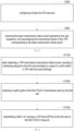
- the present application provides a beam recovery method in a multi-TRP system, including: In step S100, when a beam failure event is detected, obtaining at least one configured PUCCH resource through at least one preset dedicated SR resource, wherein the PUCCH resource is used to carry beam failure event transmission;
- the UE continuously monitors the downlink transmission beam quality corresponding to multiple TRPs, and determines that a beam failure event occurs if all downlink transmission beam qualities corresponding to one or more TRPs are lower than a preset threshold.
- Beam failure events include one TRP transmit beam failure event or multiple TRP transmit beam failure events.
- the downlink transmission beam includes the transmission beam used for the downlink control channel PDCCH or other downlink channels, etc., which will not be repeated here.
- the UE When the UE detects the beam failure event, it obtains the configured PUCCH resources according to the number of dedicated SR resources. In current protocols, there is generally only one dedicated SR resource. If two or more dedicated SR resources are configured, the number of dedicated SR resources needs to be increased through high-layer signaling, and the PUCCH resources configured by the SR resources need to be associated with specific transmission beams.
- the number of dedicated SR resources may be one, or may be the same as the number of TRPs, that is, multiple.
- the configured PUCCH resource is obtained based on the SR resource, and a PUCCH resource is associated with several (represented as N, N can be 2) beams.
- This method entails minimal deviations from the standard, as it solely requires the association of these N beams with the PUCCH resources utilized for transmitting beam failure events.
- this dedicated SR-based PUCCH resource can be used for each TRP of all cells in the same cell group, that is, each TRP in the cell group can use this dedicated SR-based PUCCH resource to report beam failure event.
- the UE sends the beam failure event on the PUCCH resource corresponding to the SR resource, the base station configures the uplink resource for the UE.
- the UE will send the beam failure recovery request (BFRQ) information to the base station through the Medium Access Control (MAC) control element (CE), including the new candidate beam information, a TRP index and CC index and other information of a TRP in which beam failure occurs.
- BFRQ beam failure recovery request
- CE Medium Access Control
- step S200 selecting the report-receiving TRP and a first beam, and using the first beam to send the beam failure event to the report-receiving TRP on the PUCCH resource, so that the base station reconfigures beams for transmission.
- the first beam is the beam used for the transmission of the reported beam transmission failure event.
- the first beam may or may not be bound with the TRP, and the PUCCH and the TRP may or may not be bound, and the corresponding relationship between the three may be combined or exist independently according to the needs of the actual scene.
- the present invention is not limited to this.
- the step of selecting the report-receiving TRP and the first beam further includes: selecting a TRP in which the beam failure event occurs as the report-receiving TRP, and selecting a corresponding pointing beam of the report-receiving TRP as the first beam.
- Non-ideal Backhaul Non-ideal Backhaul
- the high-layer signaling configures only one dedicated SR resource for configuring one PUCCH resource, and this one PUCCH resource is associated with two beams
- the PUCCH resource used to transmit the beam failure event corresponds one-to-one with the TRP where the beam failure occurs based on the actual location of the TRP where the beam failure occurred.
- the beam directed to the TRP is used to report the beam failure event through the configured PUCCH resources.
- the beam pointing to the TRP in which the beam failure occurred may be the beam corresponding to the spatial setting (Spatial Relation) used to transmit the PUCCH to the TRP for the last time before the beam failure occurred, or the beam corresponding to the spatial setting in the CORESET with the smallest index value for receiving physical downlink control channel (PDCCH), the CORESET with the smallest index value is obtained from all CORESETs configured with the same CORESETPoolIndex value, and this CORESETPoolIndex value corresponds to the TRP where the beam failure occurred.
- the spatial setting Spatial Relation
- PDCCH physical downlink control channel
- beam #1 directed to TRP1 is used to transmit PUCCH; if beam failure occurs at TRP2, beam #2 directed to TRP2 is used to transmit PUCCH.
- the step of selecting the report-receiving TRP and the first beam further includes: selecting a TRP without a beam failure event as the report-receiving TRP, and selecting its corresponding pointing beam as the first beam.
- a beam failure event of another TRP can be reported through PUCCH to the TRP with no beam failure. Therefore, if the high-layer signaling configures only one dedicated SR resource for configuring one PUCCH resource, and this one PUCCH resource is associated with two beams, according to the actual azimuth of the TRP without beam failure, a beam failure event of another TRP can be reported through PUCCH to the TRP with no beam failure.
- the beam failure event is reported through the configured PUCCH resource by using the beam pointing to the TRP without beam failure.
- the beam pointing to the TRP without beam failure may be the beam corresponding to the spatial relationship (Spatial Relation) used to transmit the PUCCH to the TRP most recently, or the beam corresponding to the spatial setting used to receive the PDCCH in the CORESET with the smallest index value.
- the beam corresponding to the Spatial Setting, the CORESET with the smallest index value is obtained from all CORESETs configured with the same CORESETPoolIndex value, and this CORESETPoolIndex value corresponds to the TRP for which no beam failure has occurred.
- the PUCCH carries a beam failure event message of the TRP1 .
- the beam used by the last PUCCH sent to the report-receiving TRP before the beam failure event is detected is selected as the first beam.
- the step of selecting the first beam further includes: selecting, as the first beam, a beam that is set in a spatial relationship used for receiving PDCCH, wherein the spatial relationship is in a control resource set with the smallest index value in the control resource set group corresponding to the report-receiving TRP, and the control resource set group corresponds to the report-receiving TRP.
- the number of PUCCH resources is two or more.
- the upper layer signaling has at most two or more dedicated SR resources
- one configured PUCCH resource can be obtained from one SR resource, and each PUCCH resource is associated with one transmit beam. Since there is only one dedicated SR resource in the current protocol, this method needs to increase the number of dedicated SR resources in high-layer signaling, and needs to associate these PUCCH resources with specific transmit beams.
- the number of dedicated SR resources may be the same as the number of TRPs, namely 2, and the PUCCH resource corresponding to each dedicated SR resource is only associated with one beam pointing to one TRP. If the TRP-level-based beam recovery mechanism is triggered, a specific beam needs to be used to report the beam failure event to a specific TRP through the PUCCH.
- mapping relationship between the PUCCH resource and the report-receiving TRP there is a mapping relationship between the PUCCH resource and the report-receiving TRP, and the step of using the first beam to send the beam failure event to the report-receiving TRP on the PUCCH resource is:
- the beam failure event is sent on the PUCCH resource corresponding to the report-receiving TRP, and the first beam is used to transmit the PUCCH to the report-receiving TRP.
- the two configured PUCCHs are obtained according to the SR resources, and the two PUCCH resources are respectively associated with the corresponding TRPs. That is, the first PUCCH resource is obtained according to the first dedicated SR resource, and the UE may use the first PUCCH resource to report a message to the first TRP.
- a second PUCCH resource may be obtained according to the second dedicated SR resource, and the UE may use the second PUCCH resource to report a message to the second TRP.
- the UE can more specifically determine the available PUCCH resources.
- the present application proposes the following method.
- the PUCCH resources used to transmit the beam failure event are in one-to-one correspondence with the TRP in which the beam failure occurred. That is: if a certain TRP has a beam failure, the beam pointing to the TRP is used to report the beam failure event through the associated PUCCH resource.
- the beam pointing to the first TRP is used to report the beam failure event on the first PUCCH resource.
- the beam pointing to the second TRP is used to report the beam failure event on the second PUCCH resources.
- the beam pointing to the TRP in which the beam failure occurred may be the beam corresponding to the spatial relationship used to transmit the PUCCH to the TRP for the last time before the beam failure occurred, or the beam corresponding to the spatial setting used to receive the PDCCH in the CORESET with the smallest index value.
- the CORESET with the smallest index value is obtained from all CORESETs configured with the same CORESETPoolIndex value, and the CORESETPoolIndex value corresponds to the TRP in which the beam failure occurred.
- beam #1 directed to TRP1 is used to report the beam failure event on the PUCCH1 resource; if a beam failure occurs at TRP2, the beam #2 directed to TRP2 is used to report the beam failure event on the PUCCH2 resource.
- the beam pointing to the TRP without beam failure can be the beam corresponding to the spatial relationship used by TRP to transmit the PUCCH most recently, or the beam corresponding to the spatial setting used to receive PDCCH in the CORESET with the smallest index value.
- the CORESET with the smallest index value is obtained from all CORESET s with the same CORESETPoolIndex value, and this CORESETPoolIndex value corresponds to the TRP for which no beam failure has occurred.
- the step of using the first beam to send the beam failure event to the report-receiving TRP on the PUCCH resource is:
- the first PUCCH resource is selected to carry the beam failure event, and the first beam is used to transmit the PUCCH to the report-receiving TRP.
- the UE can use any one of these two PUCCH resources.
- the selection method of PUCCH resources can be selecting according to the order of currently available PUCCH resources, wherein the order of PUCCH resources can be sorted according to the PUCCH resource index value. That is, the PUCCH resources are selected according to the chronological order of occurrence of TRP-level beam failure events and the order of PUCCH resources.
- the UE selects the first PUCCH resource to report the beam failure event. If the PUCCH resources are not bound with the TRP, the UE can obtain different PUCCH resources to adapt to different channel characteristics, and the PUCCH resources are fully utilized. For the method of associating transmission beams with PUCCH resources, the following methods are proposed in this paper.
- PUCCH resources are selected according to the above principles, and according to the actual azimuth of the TRP in which the beam failure occurred, the beam pointing to the TRP in which the beam failure occurred is used to report the beam failure event the selected PUCCH resource. Specifically, if a beam failure occurs in the first TRP, use the beam pointing to the first TRP to report the beam failure event on the selected PUCCH resource.
- the beam pointing to the second TRP is used to report the beam failure event on the selected PUCCH resource.
- the beam pointing to the TRP in which the beam failure occurred may be the beam corresponding to the spatial relationship used to transmit the PUCCH to the TRP for the last time before the beam failure occurred, or the beam corresponding to the spatial setting used to receive the PDCCH in the CORESET with the smallest index value.
- the CORESET with the smallest index value is obtained from all CORESETs configured with the same CORESETPoolIndex value, and the CORESETPoolIndex value corresponds to the TRP in which the beam failure occurred.
- beam #1 directed to TRP1 is used to report the beam failure event on the selected PUCCH resource. If a beam failure occurs at TRP2, beam #2 directed to TRP2 is used to report the beam failure event on the selected PUCCH resource.
- a beam pointing to the TRP without beam failure is used to report the beam failure event through the selected PUCCH resource. Specifically, if a beam failure occurs in the first TRP, the beam pointing to the second TRP is used to report the beam failure event on the selected PUCCH resource.
- the beam pointing to the first TRP is used to report the beam failure event in the selected PUCCH resource.
- the beam pointing to the TRP without beam failure may be the beam corresponding to the spatial relationship used for the latest PUCCH transmission to the TRP, or the beam corresponding to the spatial setting used to receive the PDCCH in the CORESET with the smallest index value.
- the CORESET with the smallest index value is obtained from all CORESETs configured with the same CORESETPoolIndex value, and this CORESETPoolIndex value corresponds to the TRP without beam failure.
- the beam #2 directed to TRP2 is used to report the TRP1 beam failure event message on the selected PUCCH resource.
- the beam failure event is a TRP transmit beam failure.
- the present application also provides a beam recovery method in a multi-TRP system. As shown in FIG. 10 , the method is executed at the base station and includes:
- the number of SR resources is the same as the number of TRPs.
- the SR resources are configured through RRC or acquired by the core network.
- the method before the step of receiving the beam transmission failure event reported by the user equipment and reconfiguring the transmission beam of the TRP corresponding to the beam transmission failure event, the method further includes:
- the PUCCH resource has a corresponding relationship with TRP.
- the present application provides a beam recovery method in a multi-TRP system. As shown in FIG. 11 , the method is executed on the user equipment side, including: In step ST100, when detecting a TRP-level beam transmission failure event, sending a scheduling request to the first cell according to a type of a cell to which a TRP with the event belongs;
- the UE continuously monitors the downlink transmission beam quality corresponding to multiple TRPs, and determines that a beam failure event occurs if all downlink transmission beam qualities corresponding to one or more TRPs are lower than a preset threshold.
- the beam failure event includes one TRP transmission beam failure event or multiple TRP transmission beam failure events.
- the downlink transmission beam includes the transmission beam used for the downlink control channel PDCCH or other downlink channels, etc., which will not be repeated here.
- the type of the cell to which the TRP belongs includes a secondary cell SCell, a primary cell PCell, or a primary secondary cell PSCell.
- the UE When the UE detects that a certain TRP or multiple TRPs generate a transmission beam failure event, the UE selects the first cell and sends a scheduling request to the first cell according to the preset correspondence between the cell type and the first cell.
- the first cell includes a primary cell and a secondary cell.
- Step ST200 receiving an uplink grant of the first PUSCH transmission sent by the first cell; If no dedicated SR resource is configured, the corresponding PUCCH resource cannot be obtained. In addition, if the PUCCH resources acquired through the dedicated SR resources are already occupied, when a new beam failure event needs to be reported, there will also be no available PUCCH resources.
- a conventional SR process is used to obtain an uplink grant and report BFRQ on a physical uplink shared channel (PUSCH), or report BFRQ through a physical random access channel (PRACH).
- PUSCH physical uplink shared channel
- PRACH physical random access channel
- the conventional SR resource can be used to obtain an uplink grant (UL Grant) for PUSCH transmission, and the MAC CE carrying the beam failure recovery related information is transmitted on the PUSCH, where the conventional SR resource can be obtained through high-level configuration parameters, namely: a parameter schedulingRequestResourceId under the high-level parameter SchedulingRequestResourceConfig.
- Step ST300 transmitting a MAC CE carrying a TRP-level BFRQ to the first cell on the first PUSCH resource.
- the beneficial effect of the present application is that it solves the problem that TRP performs beam recovery in the absence of dedicated SR resources.
- the cell can know the TRP in which a beam failure has occurred and in turn reconfigures the transmit beam.
- the first cell includes a primary cell and a primary secondary cell.
- the cell type of the TRP is a secondary cell
- the step of transmitting the MAC CE carrying TRP-level BFRQ to the first cell on the first PUSCH resource further includes: receiving a beam failure recovery response from the secondary cell.
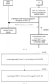
- the BFRQ reporting message based on the conventional SR resource is mainly exchanged between the UE and the PCell, and the beam failure recovery response is sent from the SCell to the UE.
- the UE performs TRP-level beam failure detection, finds that the TRP has a beam failure, and selects a new candidate beam.
- the UE sends an SR to the PCell using conventional SR resources, notifying the PCell that there is uplink data to be transmitted.
- the PCell issues an uplink grant to transmit a buffer status report (BSR).
- BSR buffer status report
- the UE sends a BSR to the PCell based on the TRP-level MAC CE carrying the BFRQ, thus, to notify the PCell of the amount of data to be transmitted in the uplink.
- the amount of data is determined by the MAC CE.
- the MAC CE mainly carries the TRP index value with beam failure, CC index value, and new candidate beam indication (if one that meets the requirements is found) and an indicator showing whether a new candidate beam is located. If there are 2 TRPs with beam failure events, the MAC CE carries the BFRQ messages of the 2 TRPs.
- the PCell sends an uplink grant to the UE according to the size of the BSR, which is used to transmit the MAC CE on the PUSCH.
- the UE transmits the corresponding MAC CE based on the uplink grant.
- the SCell sends a beam failure recovery response to the UE.
- FIG. 12 shows a process of reporting BFRQ based on conventional SR in SCell.
- the cell type of the TRP is a primary cell/primary secondary cell
- after the step of transmitting the MAC CE carrying the TRP-level BFRQ to the first cell on the first PUSCH resource further include: receiving the beam failure recovery response sent from the primary cell/primary secondary cell.
- the TRP in which the beam failure occurs belongs to the PCell/PSCell and there is no PUCCH resource corresponding to the dedicated SR resource
- the message for BFRQ reporting based on the regular SR resource is exchanged between the UE and the PCell/PSCell, and a beam failure recovery response is sent from the PCell/PScell to UE.
- the UE performs TRP-level beam failure detection, finds that the TRP has a beam failure, and selects a new candidate beam.
- the UE sends an SR to the PCell/PSCell using conventional SR resources, notifying the PCell/PSCell that there is uplink data to be transmitted.
- the PCell/PSCell issues an uplink grant for transmission of BSR.
- the UE sends a BSR to the PCell/PSCell using the TRP-level MAC CE that carries BFRQ, thus, to notify the PCell/PSCell of the amount of data to be transmitted in the uplink.
- the amount of data is determined by the MAC CE, which mainly carries the TRP index value with beam failure, CC index value, and new candidate beam indication (if the one that meets the requirements is located) and an indicator showing whether a new candidate beam is located. If there are 2 TRPs with beam failure events, the MAC CE carries the BFRQ messages of the 2 TRPs.
- the PCell/PSCell sends an uplink grant to the UE according to the size of the BSR, which is used for transmission of the MAC CE on the PUSCH.
- the UE transmits the corresponding MAC CE based on the uplink grant.
- the PCell/PSCell sends a beam failure recovery response to the UE.
- FIG. 13 shows a process of reporting BFRQ based on conventional SR in PCell/PSCell.
- the information carried by the MAC CE includes the index value of the TRP in which the beam failure occurred, the index value of the carrier component CC, the new candidate beam indication (if found to meet the requirements) and a first indicator used to indicate whether a new candidate beam is found.
- the information carried by the MAC CE further includes BFRQ messages of two TRPs.
- a MAC CE can be designed to report the BFRQ information of the two TRPs to the base station at one time on the PUSCH.
- dedicated SR resources are utilized to obtain uplink grant through the SR process, and the uplink grant is used to transmit the MAC CE carrying BFRQs for two TRPs at one time on the PUSCH.
- the cell-level dedicated SR resources can be used, or the dedicated SR resource of a specified TRP (for example, the first TRP or the second TRP) can also be used.
- the MAC CE is generated according to the BFRQ information of the two TRPs and reported to the base station at one time on the PUSCH.
- the MAC CE for the first TRP, its relevant BFRQ information is the first TRP index value, CC index value, new candidate beam indication (if found to meet the requirements) and an indicator showing whether a new candidate beam is located. Since there are two TRPs with beam failures, the MAC CE also carries the BFRQ information of the second TRP, namely the second TRP index value, CC index value, new candidate beam indication (if it is found to meet the requirements) and an indicator showing whether a new candidate beam is located. In addition, a parameter can be added to indicate the number of TRPs for which beam failures occur. Finally, in response to the BFRQ report, the base station only sends one PDCCH for scheduling a new PUSCH transmission.
- the base station reconfigures the beams of the downlink control channels of the two TRPs respectively.
- N N can be 28
- the UE uses the parameters with the same antenna port quasi-co-location characteristics as the first new beam reported in the BFRQ to monitor the PDCCH in all CORESETs where the high-level parameter CORESETPoolIndex in the SCell is 0, and uses the parameters with the same antenna port quasi-co-location characteristics as the second new beam reported in the BFRQ to monitor the PDCCH in all CORESETs where the high-level parameter CORESETPoolIndex in the SCell is 1.
- the HARQ process index value of this new PUSCH is the same as the HARQ process index value of the PUSCH that reports BFRQ, and the NDI value is inverted.
- These N symbols are counted from the last symbols of the PDCCH that is sent from the base station to respond the BFRQ report.
- both TRPs of the SCell have beam failures and a beam recovery mechanism is performed based on the two TRP-level measurement results.
- the information carried by the MAC CE further includes a BFRQ message specifying a TRP.
- a single-TRP beam recovery mechanism can be used to design a MAC CE to report to the PCell that the SCell has 2 TRP in which beam failure event occurs, and a TRP is selected, and only the BFRQ information of this TRP is reported. After the beam is recovered, both TRPs use the new beam information selected by this TRP to receive the control channel information. This approach saves time and reduces signaling overhead, but it lacks beam accuracy.
- the UE detects that beam failures have occurred in both TRPs in the SCell, and selects new candidate beams for the two TRPs respectively.
- L1-RSRP L1-Reference Signal Received Power
- the MAC CE is generated according to the BFRQ information of this TRP and reported to the PCell on the PUSCH.
- the base station sends a PDCCH to schedule a new PUSCH transmission.
- the base station reconfigures the beams of the downlink control channels corresponding to the two TRPs.
- N can be 28 symbols
- the UE monitors the PDCCH in all CORESETs in the SCell using the parameters that have the same antenna port quasi-co-location characteristics as the new beam reported in the BFRQ.
- the HARQ process index value of this new PUSCH is the same as the HARQ process index value of the PUSCH reporting BFRQ, and the NDI value is inverted.
- These N symbols are counted from the last symbols of the PDCCH that is sent from the base station to respond to the BFRQ report.
- both TRPs of the SCell have beam failures, and a beam recovery mechanism is performed based on one TRP-level measurement results.
- the method before the step when detecting a TRP-level beam transmission failure event, the method further includes: receiving the beam failure detection reference signal BFD-RS and the new beam identification reference signal NBI-RS configured by higher layer signaling.
- BFD-RS cell-level beam failure detection reference signal
- NBI-RS new beam identification reference signal
- PBCH Physical Broadcast Channel
- CSI-RS periodic channel state information reference Signal
- cell-level beam failure event counter i.e., BFI_COUNTER
- cell-level beam failure detection timer e.g., high-level parameter beamFailureDetectionTimer
- cell level dedicated SR resource index used to transmit beams failure request information
- the beam failure event counter, beam failure detection timer, and dedicated SR resource index can reuse the corresponding parameters of a certain TRP in the TRP level parameters, for example, use the beam failure event counter, beam failure detection timer and dedicated SR resource index of the TRP (i.e., the first TRP) corresponding to the high-level parameter CORESETPoolIndex value of 0 can also use the corresponding parameters of the second TRP.
- the method before the step of receiving the uplink grant of the first PUSCH transmission fed back by the first cell in step S200, the method further includes:
- Step ST210 receiving an uplink grant for transmission of the MAC CE
- Step ST220 reporting the BSR to the first cell through the MAC CE.
- the UE switches to the cell-level beam recovery mechanism, reuses the above-defined variables and high-level parameters for beam failure detection and selection of new candidate beams, and reports a beam failure recovery request to the base station in the form of MAC CE. If a new candidate beam is found, the MAC CE only carries a new candidate beam and CC index value. If no new candidate beam is found, it carries an indication that there is no candidate beam and CC index value that meet the standard.
- the base station schedules a new PUSCH by sending the PDCCH as a response to the BFRQ report, wherein the HARQ process index value of the new PUSCH is the same as the HARQ process index value of the PUSCH used for reporting BFRQ, and the NDI value is inverted.
- the base station reconfigures the beam of the downlink control channel.
- N can be 28
- the UE monitors the PDCCH in all CORESETs in the SCell using the parameters that have the same antenna port quasi-co-location characteristics as the new beam reported in the BFRQ, where the N symbols are numbered from the last symbol of the PDCCH that is sent by the base station to respond to the BFRQ reporting.
- both TRPs of the SCell have beam failures and use the cell-level beam recovery mechanism.
- the present application also provides a beam recovery method in a multi-TRP system. As shown in FIG. 18 , the method is executed at the base station, including:
- the method further includes: scheduling a new PUSCH through the PDCCH as a response to the reported BFRQ message.
- the HARQ process index value of the new PUSCH is the same as the HARQ process index value of a PUSCH of the reported BFRQ, and the NDI value is inverted.
- the step of reconfiguring the transmission beam of at least one TRP according to the BFRQ message includes:
- the BFRQ message is a BFRQ message of one TRP, and beam reconfiguration is performed on the TRP, and the configuration is reused to at least one other TRP.
- the present application also provides a beam recovery method in a multi-TRP system. As shown in FIG. 19 , the method is performed on the user equipment side, including:
- the PRACH channel can be used to report the BFRQ information, wherein the PRACH resource for transmitting beam failure information can be obtained through a high-level parameter (i.e., a high-level parameter PRACH-ResourceDedicatedBFR).
- a high-level parameter i.e., a high-level parameter PRACH-ResourceDedicatedBFR
- the PRACH resource used for transmitting beam failure information is selected according to the new candidate beam, and the beam failure event is reported on the PRACH channel.
- the base station obtains the new candidate beam information reported by the UE through the detected PRACH channel.
- the UE uses the same antenna port quasi-co-location parameter as the new candidate beam to monitor PDCCH in the search space set indicated by the beam recovery search space index value configured by the high-level signaling (for example, high-level parameter recoverySearchSpaceId), until the UE receives the MAC CE for activating the transmission configuration indicator (TCI) state or receives the high-level parameters for activating and releasing the TCI state (i.e., tci-StatesPDCCHToAddList and tci-StatesPDCCH-ToReleaseList).
- TCI transmission configuration indicator
- the time slot where the starting point of this time window is located is (n+N), and N can be 4.
- This time window is configured according to the parameter beamFailureRecoveryTimer under the high-level parameter BeamFailureRecoveryConfig. If the PDCCH is detected, the reported beam failure event and the new candidate beam are considered to be received by the base station, and at the same time, the base station reconfigures the beam of the downlink control channel.
- the reference signal can be SSB (SS/PBCH Block) or periodic CSI-RS. Since it is a cell-level reference signal, each reference signal covers a larger angle, so the cell-level reference signal is different from the TRP-level reference signal.
- the cell-level beam failure event counter i.e., BFI_COUNTER
- other cell-level high-level parameters such as cell-level beam failure detection timer (i.e., high-level parameter beamFailureDetectionTimer)
- the cell level PRACH resource used to transmit beam failure information for example, high layer parameter PRACH-ResourceDedicatedBFR.
- the beam failure event counter and beam failure detection timer can reuse the corresponding parameters of a certain TRP in the TRP level parameters.
- the beam failure event counter and beam failure detection timer of the TRP corresponding to the high-level parameter CORESETPoolIndex value of 0 is used, and the corresponding parameters of the second TRP can also be used.
- both TRPs in the PCell/PSCell detect a beam failure event
- the UE switches to the cell-level beam recovery mechanism, and reuses the above-defined variables and high-level parameters for beam failure detection and selection of new candidate beams.
- the new candidate beam selected according to the Cell-level reference signal, and a PRACH resource is selected for transmitting beam failure information.
- the beam failure events are reported on a PRACH channel.
- the base station obtains the new candidate beam information reported by the UE through the detected PRACH channel.
- the UE uses the parameters that have the same antenna port quasi-co-location characteristics as the new candidate beam to monitor the PDCCH in the search space set indicated by beam recovery search space index value configured by the high layer signaling (e.g., high layer The parameter recoverySearchSpaceId), until the UE receives the MAC CE for activating the TCI state or the higher-layer parameters for activating and releasing the TCI state (i.e., tci-StatesPDCCHToAddList and tci-StatesPDCCH -ToReleaseList).
- the high layer signaling e.g., high layer The parameter recoverySearchSpaceId
- the time slot where the starting point of this time window is located is (n+N), and N can be 4.
- This time window is configured according to the parameter beamFailureRecoveryTimer under the high-level parameter BeamFailureRecoveryConfig. If the PDCCH is detected, the reported beam failure event and the new candidate beam are considered to be received by the base station. At the same time, the base station reconfigures the beam of the downlink control channel. As shown in FIG. 20 , both TRPs of PCell/PSCell have beam failures and use the cell-level beam recovery mechanism.
- the beam transmission failure event is a beam transmission failure event of two TRPs.
- the step of selecting PRACH resource corresponding to the new candidate beam, and the sending the beam transmission failure event on the PRACH resource to base station includes:
- both TRPs in the PCell/PSCell have a beam failure event and use the cell-level beam recovery mechanism, all TRPs in the cell use the same new beam, and the downlink control channels of different TRPs with spatial characteristics cannot be fully utilized to configure different beams.
- the BFRQ of the first TRP can be sent through the PRACH channel to recover the first TRP
- BFRQ of the second TRP can be sent through the PRACH channel to recovers the second TRP.
- the second TRP can be recovered before recovering the first TRP.
- different beams can be configured for different TRPs.
- the PRACH resource used for transmitting the beam failure information of the first TRP is selected according to the new candidate beam of the first TRP, and the beam failure event of the first TRP is reported on the PRACH channel.
- the base station obtains the new candidate beam information of the first TRP reported by the UE through the detected PRACH channel.
- the UE uses the parameters that have the same antenna port quasi-co-location characteristics as the new candidate beam to monitor the PDCCH in the search space set indicated by the first beam recovery search space index value (e.g., the high-level parameter recoverySearchSpaceId1), until the UE receives the MAC CE for activating the TCI state or receives the high-level parameters for activating and releasing the TCI state (i.e., tci-StatesPDCCHToAddList and tci-StatesPDCCH-ToReleaseList).
- the first beam recovery search space index value e.g., the high-level parameter recoverySearchSpaceId1
- the time slot where the starting point of this time window is located is (n+N), and N can be 4.
- This time window is configured according to the parameter beamFailureRecoveryTimer under the high-level parameter BeamFailureRecoveryConfig. If the PDCCH is detected, it is considered that the reported beam failure event of the first TRP and the new candidate beam are received by the base station. At the same time, the base station reconfigures the beam of the downlink control channel of the first TRP.
- the PRACH resource for transmitting the beam failure information of the second TRP is selected according to the new candidate beam of the second TRP, and the beam failure event of the second TRP is reported on the PRACH channel.
- the base station detects PRACH channel to receive new candidate beam information of the second TRP reported by the UE.
- the UE uses the parameters that have the same antenna port quasi-co-location characteristics as the new candidate beam to monitor the PDCCH in the search space set indicated by the second beam recovery search space index value (e.g., the high-level parameter recoverySearchSpaceId2), until the UE receives the MAC CE for activating the TCI state or receives the high-level parameters for activating and releasing the TCI state (i.e., tci-StatesPDCCHToAddList and tci-StatesPDCCH-ToReleaseList). If the PDCCH is detected, the reported beam failure event of the second TRP and the new candidate beam are considered to be received by the base station.
- the second beam recovery search space index value e.g., the high-level parameter recoverySearchSpaceId2
- the base station reconfigures the beam of the downlink control channel of the second TRP.
- beam failure occurs on both TRPs of PCell/PSCell and the first TRP is recovered first and then the second TRP is recovered.
- the present application also provides a beam recovery method in a multi-TRP system. As shown in FIG. 22 , the method is executed at the base station, including:
- the step of reconfiguring the transmission beam of at least one TRP according to the new candidate beam comprises: reconfiguring a TRP transmission beam corresponding to the new candidate beam according to the new candidate beam, and reusing a beam configuration of the TRP to at least one other TRP.
- the UE uses PRACH to simultaneously send the BFRQs of the two TRPs to the base station.
- the base station simultaneously recovers two TRPs according to the beam of one of the TRPs. In this way, time can be further saved, but another TRP may not necessarily obtain the best beam.
- the PRACH resource used for transmitting the beam failure information of the first TRP is selected according to the new candidate beam of the first TRP, and the beam failure event of the first TRP is reported on the PRACH channel.
- the base station obtains the new candidate beam information of the first TRP reported by the UE through the detected PRACH channel.
- the PRACH resource for transmitting the beam failure information of the second TRP is selected, the beam failure event of the second TRP is reported on the PRACH channel.
- the base station detects the PRACH channel.
- the base station If the base station can detect the PRACH channel and obtain the new candidate beam information of the second TRP reported by the UE at the same time or within a period of time (the time length is configured by the base station), the base station determines that both TRPs have a beam failure event, and uses a new candidate beam of one of the TRPs (pre-designated by the base station, which can be the first TRP or the second TRP) to recover the two TRPs.
- the UE uses the parameters that have the same antenna port quasi-co-location characteristics as the new candidate beam of the corresponding TRP to monitor the PDCCH in the search space set indicated by the beam recovery search space index value (e.g., the high-level parameter recoverySearchSpaceId), until the UE receives the MAC CE for activating the TCI state or receives the high-level parameters for activating and releasing the TCI state (i.e., tci-StatesPDCCHToAddList and tci-StatesPDCCH-ToReleaseList).
- the beam recovery search space index value e.g., the high-level parameter recoverySearchSpaceId
- the time slot where the starting point of this time window is located is (n+N), and N can be 4.
- This time window is configured according to the parameter beamFailureRecoveryTimer under the high-level parameter BeamFailureRecoveryConfig.
- the base station reconfigures the beams of the downlink control channels of the two TRPs. As shown in FIG. 23 , beam failure occurs on both TRPs of PCell/PSCell, and a beam recovery mechanism is performed based on one TRP-level measurement result.
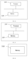
- the present application also provides a communication device comprising a processor 110 and a memory 120.
- the processor 110 controls the operation of the communication device, and the processor 110 may also be referred to as a central processing unit (CPU).
- the processor 110 may be an integrated circuit chip with processing capability for processing signal sequence.
- the processor 110 may also be a general purpose processor, digital signal sequence processor (DSP), application specific integrated circuit (ASIC), field programmable gate array (FPGA), or other programmable logic device, discrete gate or transistor logic device, or discrete hardware components.
- DSP digital signal sequence processor
- ASIC application specific integrated circuit
- FPGA field programmable gate array
- a general purpose processor may be a microprocessor or the processor may be any conventional processor or the like.
- the memory 120 stores instructions and data required for the operation of the processor 110.
- the processor 110 is configured to execute instructions to implement the steps executed by the base station according to the embodiments of the present application.
- the second embodiment of the communication device of the present application includes a processor 210 and a memory 220.
- the processor 210 controls the operation of the communication device.
- the processor 210 may also be referred to as a central processing unit (CPU).
- the processor 210 may be an integrated circuit chip, which has the processing capability of signal sequence.
- Processor 210 may also be a general purpose processor, digital signal sequence processor (DSP), application specific integrated circuit (ASIC), field programmable gate array (FPGA) or other programmable logic device, discrete gate or transistor logic, discrete hardware components.
- DSP digital signal sequence processor
- ASIC application specific integrated circuit
- FPGA field programmable gate array
- a general purpose processor may be a microprocessor, or the processor may be any conventional processor or the like.
- Memory 220 stores instructions and data required for processor 210 to operate.
- the processor 210 is configured to execute instructions to implement the methods executed by the user equipment side in the embodiments of the present application.
- an embodiment of the readable storage medium of the present application includes a memory 310.
- the memory 310 stores an instruction, and when the instruction is executed, implements the method provided by any embodiment of the present application and a possible combination thereof.
- the memory 310 may include a read-only memory (ROM), a random access memory (RAM), a flash memory (Flash Memory), a hard disk, an optical disk, and the like.
- ROM read-only memory
- RAM random access memory
- flash memory Flash Memory
- the disclosed method and apparatus may be implemented in other manners.
- the device implementations described above are only illustrative.
- the division of the modules or units is only a logical function division. In actual implementation, there may be other divisions.
- multiple units or components may be combined or integrated into another system, or some features can be omitted, or not implemented.
- the mutual coupling or direct coupling or communication connection shown or discussed may be through some interfaces, indirect coupling or communication connection of devices or units, which may be in electrical, mechanical or other forms.
- the units described as separate components may or may not be physically separated.
- Components displayed as units may or may not be physical units, that is, may be located in one place, or may be distributed to multiple network units. Some or all of the units may be selected according to actual needs to achieve the purpose of the solution in the embodiments.
- each functional unit in each embodiment of the present application may be integrated in one processing unit, or each unit may be physically included individually, or two or more units may be integrated in one unit.
- the above-mentioned integrated units can be implemented in the form of hardware or in the form of software functional units.
- the integrated unit is implemented in the form of a software functional unit and sold or used as an independent product, it can be stored in a computer-readable storage medium.
- the computer software products are stored in a storage medium, including several instructions for causing a computer device (which may be a personal computer, a server, or a network device, etc.) or a processor (processor) to execute all or part of the steps of the methods described in the various embodiments of the present application.
- the aforementioned storage medium includes universal serial bus (USB) disk, portable hard disk, read-only memory (ROM), random access memory (RAM), magnetic disk or optical disk and other media that can store program codes.
Landscapes
- Engineering & Computer Science (AREA)
- Signal Processing (AREA)
- Computer Networks & Wireless Communication (AREA)
- Mobile Radio Communication Systems (AREA)
Applications Claiming Priority (1)
| Application Number | Priority Date | Filing Date | Title |
|---|---|---|---|
| PCT/CN2021/072506 WO2022151477A1 (zh) | 2021-01-18 | 2021-01-18 | 一种多trp系统的波束恢复方法、通信设备及可读存储介质 |
Publications (2)
| Publication Number | Publication Date |
|---|---|
| EP4280656A1 true EP4280656A1 (de) | 2023-11-22 |
| EP4280656A4 EP4280656A4 (de) | 2024-10-16 |
Family
ID=82446831
Family Applications (1)
| Application Number | Title | Priority Date | Filing Date |
|---|---|---|---|
| EP21918677.2A Pending EP4280656A4 (de) | 2021-01-18 | 2021-01-18 | Strahlwiederherstellungsverfahren für multi-trp-system, kommunikationsvorrichtung und lesbares speichermedium |
Country Status (4)
| Country | Link |
|---|---|
| US (1) | US20240073710A1 (de) |
| EP (1) | EP4280656A4 (de) |
| CN (1) | CN116762444A (de) |
| WO (1) | WO2022151477A1 (de) |
Cited By (1)
| Publication number | Priority date | Publication date | Assignee | Title |
|---|---|---|---|---|
| WO2025170675A1 (en) * | 2024-02-06 | 2025-08-14 | Intel Corporation | Ue-initiated beam management |
Families Citing this family (3)
| Publication number | Priority date | Publication date | Assignee | Title |
|---|---|---|---|---|
| CN115119225B (zh) * | 2021-03-22 | 2026-02-27 | 北京紫光展锐通信技术有限公司 | 一种信息传输方法及装置 |
| CN115190497A (zh) * | 2021-04-01 | 2022-10-14 | 华为技术有限公司 | 波束失败恢复方法,装置及可读存储介质 |
| US12549242B2 (en) * | 2021-08-02 | 2026-02-10 | Qualcomm Incorporated | Identification of a beam failure detection reference signal and a new beam identification reference signal |
Family Cites Families (26)
| Publication number | Priority date | Publication date | Assignee | Title |
|---|---|---|---|---|
| WO2019051242A2 (en) * | 2017-09-08 | 2019-03-14 | Convida Wireless, Llc | COMMUNICATION MANAGEMENT USING DOWNLINK COMMAND INFORMATION |
| CN110505692B (zh) * | 2018-05-16 | 2022-02-22 | 维沃移动通信有限公司 | 一种多载波系统中的波束失败恢复方法及装置 |
| CN110719154B (zh) * | 2018-07-12 | 2021-06-01 | 维沃移动通信有限公司 | 一种波束失败恢复请求传输方法及设备 |
| CN112673579B (zh) * | 2018-07-12 | 2024-03-19 | 株式会社Ntt都科摩 | 终端、无线通信方法以及系统 |
| ES2998787T3 (en) * | 2019-01-11 | 2025-02-21 | Lenovo Beijing Ltd | Method and apparatus for beam failure recovery |
| CN111278122B (zh) * | 2019-01-25 | 2023-03-24 | 维沃移动通信有限公司 | 波束失败恢复方法、处理方法、终端及网络侧设备 |
| US11363516B2 (en) * | 2019-03-27 | 2022-06-14 | Mediatek Singapore Pte. Ltd. | Electronic device and method for beam failure recovery |
| CN111615118B (zh) * | 2019-04-30 | 2022-06-07 | 维沃移动通信有限公司 | 波束恢复方法及设备 |
| US11211990B2 (en) * | 2019-05-01 | 2021-12-28 | Ofinno, Llc | Beam failure recovery in multi-TRP scenarios |
| JP7320762B2 (ja) * | 2019-06-06 | 2023-08-04 | 株式会社Nttドコモ | 端末、無線通信方法及びシステム |
| US11903069B2 (en) * | 2019-08-16 | 2024-02-13 | Intel Corporation | Beam failure recovery in secondary cells |
| WO2021115204A1 (en) * | 2019-12-10 | 2021-06-17 | Guangdong Oppo Mobile Telecommunications Corp., Ltd. | Method and apparatus of scell beam failure recovery |
| SG10202001583TA (en) * | 2020-02-22 | 2021-09-29 | Panasonic Ip Corp America | Beam failure recovery for single dci-based m-trp urllc transmissions |
| US12418337B2 (en) * | 2020-04-08 | 2025-09-16 | Interdigital Patent Holdings, Inc. | Methods, apparatuses and systems directed to beam management in connection with multiple cells and/or multiple transmission/reception points |
| CN113645649A (zh) * | 2020-05-11 | 2021-11-12 | 索尼公司 | 用于无线通信的电子设备和方法、计算机可读存储介质 |
| US12069760B2 (en) * | 2020-09-25 | 2024-08-20 | Qualcomm Incorporated | Response for TRP specific BFRQ and beam reset |
| US12074680B2 (en) * | 2020-09-25 | 2024-08-27 | Qualcomm Incorporated | Transmission receive point (TRP)-specific beam failure recovery request (BFRQ) |
| US11843502B2 (en) * | 2020-09-25 | 2023-12-12 | Qualcomm Incorporated | Configuration of physical uplink control channel (PUCCH)-beam failure recovery (BFR) for transmission reception point (TRP) specific BFR |
| US12200513B2 (en) * | 2020-09-29 | 2025-01-14 | Qualcomm Incorporated | Beam group specific medium access control-control element (MAC-CE) based beam failure recovery (BFR) requests |
| US20230412240A1 (en) * | 2020-09-30 | 2023-12-21 | Lenovo (Beijing) Limited | Method and apparatus for beam failure recovery in multi-dci based multiple trps |
| CN117119502A (zh) * | 2020-10-02 | 2023-11-24 | 苹果公司 | 多trp操作中的波束管理 |
| US11943037B2 (en) * | 2020-10-05 | 2024-03-26 | Samsung Electronics Co., Ltd. | Method and apparatus for beam failure recovery in a wireless communication system |
| CN114390566A (zh) * | 2020-10-22 | 2022-04-22 | 索尼公司 | 电子设备、无线通信方法和非暂态计算机可读存储介质 |
| US20220132517A1 (en) * | 2020-10-23 | 2022-04-28 | Samsung Electronics Co., Ltd. | Method and apparatus for partial beam failure recovery in a wireless communications system |
| US20240007879A1 (en) * | 2020-12-04 | 2024-01-04 | Lenovo (Beijing) Limited | Mac ce based beam failure recovery in multiple trp scenario |
| KR20220152791A (ko) * | 2021-05-10 | 2022-11-17 | 삼성전자주식회사 | 무선 통신 시스템에서 네트워크 협력 통신의 빔 실패 회복을 위한 방법 및 장치 |
-
2021
- 2021-01-18 WO PCT/CN2021/072506 patent/WO2022151477A1/zh not_active Ceased
- 2021-01-18 EP EP21918677.2A patent/EP4280656A4/de active Pending
- 2021-01-18 US US18/261,846 patent/US20240073710A1/en active Pending
- 2021-01-18 CN CN202180091175.6A patent/CN116762444A/zh active Pending
Cited By (1)
| Publication number | Priority date | Publication date | Assignee | Title |
|---|---|---|---|---|
| WO2025170675A1 (en) * | 2024-02-06 | 2025-08-14 | Intel Corporation | Ue-initiated beam management |
Also Published As
| Publication number | Publication date |
|---|---|
| WO2022151477A1 (zh) | 2022-07-21 |
| CN116762444A (zh) | 2023-09-15 |
| EP4280656A4 (de) | 2024-10-16 |
| US20240073710A1 (en) | 2024-02-29 |
Similar Documents
| Publication | Publication Date | Title |
|---|---|---|
| US11539422B2 (en) | Beam management method, terminal, network device, and storage medium | |
| EP3836693B1 (de) | Verfahren und vorrichtung zur wiederherstellung nach verbindungsfehler | |
| US11363575B2 (en) | Uplink information sending method and apparatus and uplink information receiving method and apparatus | |
| CN110754106B (zh) | 一种无线链路监控方法和装置 | |
| EP3096481B1 (de) | Signalübertragungsverfahren und -vorrichtung | |
| EP4280656A1 (de) | Strahlwiederherstellungsverfahren für multi-trp-system, kommunikationsvorrichtung und lesbares speichermedium | |
| US11622383B2 (en) | Method and device for channel sensing and signal transmission | |
| US12137002B2 (en) | Method and apparatus for determining enhanced dynamic HARQ-ACK codebook | |
| CN110859003A (zh) | 确定上行资源的方法与装置 | |
| US12063548B2 (en) | Method and apparatus for link status notification | |
| CN108632981B (zh) | 一种下行同步信号发送方法和接收方法及设备 | |
| EP4280739A1 (de) | Verfahren und vorrichtung zur erzeugung und meldung von strahlausfallinformationen | |
| CN114503725B (zh) | 服务小区的波束故障恢复 | |
| US11785661B2 (en) | Configuration method and apparatus for beam failure recovery and communication system | |
| US12107717B2 (en) | Beam failure recovery method and device and communication system | |
| CN112585928B (zh) | Harq反馈传输 | |
| US11997519B2 (en) | Method and apparatus for receiving and transmitting configuration information and communication system | |
| US20250048395A1 (en) | Sidelink positioning reference signal transmitting method and apparatus, and sidelink positioning reference signal receiving method and apparatus | |
| JP7758848B2 (ja) | 信号を送受信する方法及び装置、並びに通信システム | |
| WO2020089779A1 (en) | Methods and nodes for performing random access in case of lbt failure | |
| CN109155990A (zh) | 一种计数方法及装置 | |
| US11496248B2 (en) | Method and apparatus for transmitting HARQ information, and computer storage medium | |
| EP4664784A1 (de) | Kommunikationsverfahren, -vorrichtung und -system | |
| CN116171592A (zh) | 支持trp特定波束故障恢复的增强 |
Legal Events
| Date | Code | Title | Description |
|---|---|---|---|
| STAA | Information on the status of an ep patent application or granted ep patent |
Free format text: STATUS: THE INTERNATIONAL PUBLICATION HAS BEEN MADE |
|
| PUAI | Public reference made under article 153(3) epc to a published international application that has entered the european phase |
Free format text: ORIGINAL CODE: 0009012 |
|
| STAA | Information on the status of an ep patent application or granted ep patent |
Free format text: STATUS: REQUEST FOR EXAMINATION WAS MADE |
|
| 17P | Request for examination filed |
Effective date: 20230721 |
|
| AK | Designated contracting states |
Kind code of ref document: A1 Designated state(s): AL AT BE BG CH CY CZ DE DK EE ES FI FR GB GR HR HU IE IS IT LI LT LU LV MC MK MT NL NO PL PT RO RS SE SI SK SM TR |
|
| DAV | Request for validation of the european patent (deleted) | ||
| DAX | Request for extension of the european patent (deleted) | ||
| A4 | Supplementary search report drawn up and despatched |
Effective date: 20240913 |
|
| RIC1 | Information provided on ipc code assigned before grant |
Ipc: H04B 7/06 20060101ALI20240909BHEP Ipc: H04B 7/024 20170101ALI20240909BHEP Ipc: H04W 72/04 20230101ALI20240909BHEP Ipc: H04W 24/02 20090101AFI20240909BHEP |