EP4280590A1 - Imaging device, imaging control method, and program - Google Patents
Imaging device, imaging control method, and program Download PDFInfo
- Publication number
- EP4280590A1 EP4280590A1 EP21919573.2A EP21919573A EP4280590A1 EP 4280590 A1 EP4280590 A1 EP 4280590A1 EP 21919573 A EP21919573 A EP 21919573A EP 4280590 A1 EP4280590 A1 EP 4280590A1
- Authority
- EP
- European Patent Office
- Prior art keywords
- timing
- exposure
- margin
- image
- control
- Prior art date
- Legal status (The legal status is an assumption and is not a legal conclusion. Google has not performed a legal analysis and makes no representation as to the accuracy of the status listed.)
- Pending
Links
- 238000003384 imaging method Methods 0.000 title claims abstract description 198
- 238000000034 method Methods 0.000 title claims description 37
- 238000012545 processing Methods 0.000 claims description 62
- 206010010071 Coma Diseases 0.000 claims description 49
- 238000012937 correction Methods 0.000 claims description 48
- 230000015654 memory Effects 0.000 description 41
- 230000009471 action Effects 0.000 description 39
- 230000008569 process Effects 0.000 description 26
- 206010073261 Ovarian theca cell tumour Diseases 0.000 description 19
- 238000005516 engineering process Methods 0.000 description 19
- 208000001644 thecoma Diseases 0.000 description 19
- 230000008859 change Effects 0.000 description 12
- 238000004891 communication Methods 0.000 description 12
- 208000003443 Unconsciousness Diseases 0.000 description 11
- 238000003860 storage Methods 0.000 description 10
- 238000001514 detection method Methods 0.000 description 8
- 230000003287 optical effect Effects 0.000 description 8
- 238000010586 diagram Methods 0.000 description 7
- 230000004044 response Effects 0.000 description 7
- 230000007246 mechanism Effects 0.000 description 6
- 239000003086 colorant Substances 0.000 description 5
- 230000000694 effects Effects 0.000 description 5
- 230000014759 maintenance of location Effects 0.000 description 5
- 230000003111 delayed effect Effects 0.000 description 4
- 230000010354 integration Effects 0.000 description 4
- 238000010606 normalization Methods 0.000 description 4
- 238000002360 preparation method Methods 0.000 description 4
- 230000015572 biosynthetic process Effects 0.000 description 3
- 230000015556 catabolic process Effects 0.000 description 3
- 238000006243 chemical reaction Methods 0.000 description 3
- 238000006731 degradation reaction Methods 0.000 description 3
- 230000002349 favourable effect Effects 0.000 description 3
- 230000006870 function Effects 0.000 description 2
- 238000005286 illumination Methods 0.000 description 2
- 230000006872 improvement Effects 0.000 description 2
- 239000004973 liquid crystal related substance Substances 0.000 description 2
- 239000011159 matrix material Substances 0.000 description 2
- 230000004048 modification Effects 0.000 description 2
- 238000012986 modification Methods 0.000 description 2
- 230000000717 retained effect Effects 0.000 description 2
- 239000004065 semiconductor Substances 0.000 description 2
- 230000001360 synchronised effect Effects 0.000 description 2
- 238000003786 synthesis reaction Methods 0.000 description 2
- RUXQWZJWMCHCHH-IZZDOVSWSA-N [(e)-1-pyridin-2-ylethylideneamino]urea Chemical compound NC(=O)N\N=C(/C)C1=CC=CC=N1 RUXQWZJWMCHCHH-IZZDOVSWSA-N 0.000 description 1
- 230000009286 beneficial effect Effects 0.000 description 1
- 230000000295 complement effect Effects 0.000 description 1
- 230000006835 compression Effects 0.000 description 1
- 238000007906 compression Methods 0.000 description 1
- 230000006735 deficit Effects 0.000 description 1
- 230000001934 delay Effects 0.000 description 1
- 238000005401 electroluminescence Methods 0.000 description 1
- 238000009432 framing Methods 0.000 description 1
- 230000001771 impaired effect Effects 0.000 description 1
- 230000010365 information processing Effects 0.000 description 1
- 210000004185 liver Anatomy 0.000 description 1
- 238000012423 maintenance Methods 0.000 description 1
- 229910044991 metal oxide Inorganic materials 0.000 description 1
- 150000004706 metal oxides Chemical class 0.000 description 1
- 238000006303 photolysis reaction Methods 0.000 description 1
- 238000003825 pressing Methods 0.000 description 1
- 238000001454 recorded image Methods 0.000 description 1
- 238000011946 reduction process Methods 0.000 description 1
- 239000000758 substrate Substances 0.000 description 1
- 238000012546 transfer Methods 0.000 description 1
Images


Classifications
-
- H—ELECTRICITY
- H04—ELECTRIC COMMUNICATION TECHNIQUE
- H04N—PICTORIAL COMMUNICATION, e.g. TELEVISION
- H04N23/00—Cameras or camera modules comprising electronic image sensors; Control thereof
- H04N23/70—Circuitry for compensating brightness variation in the scene
- H04N23/745—Detection of flicker frequency or suppression of flicker wherein the flicker is caused by illumination, e.g. due to fluorescent tube illumination or pulsed LED illumination
-
- H—ELECTRICITY
- H04—ELECTRIC COMMUNICATION TECHNIQUE
- H04N—PICTORIAL COMMUNICATION, e.g. TELEVISION
- H04N23/00—Cameras or camera modules comprising electronic image sensors; Control thereof
- H04N23/60—Control of cameras or camera modules
- H04N23/63—Control of cameras or camera modules by using electronic viewfinders
-
- H—ELECTRICITY
- H04—ELECTRIC COMMUNICATION TECHNIQUE
- H04N—PICTORIAL COMMUNICATION, e.g. TELEVISION
- H04N23/00—Cameras or camera modules comprising electronic image sensors; Control thereof
- H04N23/60—Control of cameras or camera modules
- H04N23/665—Control of cameras or camera modules involving internal camera communication with the image sensor, e.g. synchronising or multiplexing SSIS control signals
-
- H—ELECTRICITY
- H04—ELECTRIC COMMUNICATION TECHNIQUE
- H04N—PICTORIAL COMMUNICATION, e.g. TELEVISION
- H04N23/00—Cameras or camera modules comprising electronic image sensors; Control thereof
- H04N23/60—Control of cameras or camera modules
- H04N23/667—Camera operation mode switching, e.g. between still and video, sport and normal or high- and low-resolution modes
-
- H—ELECTRICITY
- H04—ELECTRIC COMMUNICATION TECHNIQUE
- H04N—PICTORIAL COMMUNICATION, e.g. TELEVISION
- H04N23/00—Cameras or camera modules comprising electronic image sensors; Control thereof
- H04N23/80—Camera processing pipelines; Components thereof
-
- H—ELECTRICITY
- H04—ELECTRIC COMMUNICATION TECHNIQUE
- H04N—PICTORIAL COMMUNICATION, e.g. TELEVISION
- H04N23/00—Cameras or camera modules comprising electronic image sensors; Control thereof
- H04N23/80—Camera processing pipelines; Components thereof
- H04N23/81—Camera processing pipelines; Components thereof for suppressing or minimising disturbance in the image signal generation
-
- H—ELECTRICITY
- H04—ELECTRIC COMMUNICATION TECHNIQUE
- H04N—PICTORIAL COMMUNICATION, e.g. TELEVISION
- H04N25/00—Circuitry of solid-state image sensors [SSIS]; Control thereof
- H04N25/60—Noise processing, e.g. detecting, correcting, reducing or removing noise
- H04N25/62—Detection or reduction of noise due to excess charges produced by the exposure, e.g. smear, blooming, ghost image, crosstalk or leakage between pixels
-
- H—ELECTRICITY
- H04—ELECTRIC COMMUNICATION TECHNIQUE
- H04N—PICTORIAL COMMUNICATION, e.g. TELEVISION
- H04N25/00—Circuitry of solid-state image sensors [SSIS]; Control thereof
- H04N25/70—SSIS architectures; Circuits associated therewith
- H04N25/76—Addressed sensors, e.g. MOS or CMOS sensors
- H04N25/7795—Circuitry for generating timing or clock signals
-
- H—ELECTRICITY
- H04—ELECTRIC COMMUNICATION TECHNIQUE
- H04N—PICTORIAL COMMUNICATION, e.g. TELEVISION
- H04N25/00—Circuitry of solid-state image sensors [SSIS]; Control thereof
- H04N25/50—Control of the SSIS exposure
- H04N25/53—Control of the integration time
- H04N25/531—Control of the integration time by controlling rolling shutters in CMOS SSIS
Definitions
- the present technology relates to an imaging apparatus, an imaging control method, and a program, particularly, to a technology for capturing an image with a reduced influence of a flicker.
- An image captured by an imaging apparatus may be influenced by a flicker.
- a flicker For example, regarding a fluorescent lamp which has been widely used as an indoor light source, an LED (Light Emitting Diode) which has recently been increasingly widely used, or the like, flashing of illumination light, what is called flicker, periodically occurs due to an influence of a commercial power source frequency.
- flicker flashing of illumination light, what is called flicker, periodically occurs due to an influence of a commercial power source frequency.
- a decrease in image quality, such as color unevenness, due to such a flicker occurs.
- PTL 1 below discloses a technology for performing what is called flickerless imaging, where an influence of a flicker is reduced by detecting a period and a timing of a peak of a flicker component and performing a control to synchronize a timing of exposure with the peak timing.
- a user herein mainly refers to a person who uses a camera to capture an image
- determine a shooting timing by checking an image, namely, a live view image, displayed on a display unit such as a display panel or an EVF (electric viewfinder) disposed in a back surface of a camera, and operate a release button (a shutter button).
- a release button a shutter button
- PTL 2 discloses a technology for avoiding a blackout.
- the same live view image may continuously appear for multiple times depending on a timing of imaging, causing a change of a frame rate for a user to see or a change of a duration length (latency) from exposure to the display of a live view image.
- Such a variation in frame rate for a user to see or a variation in latency results in a failure of a smooth live view image to be displayed, which may make it difficult for a user to perform framing while looking at the live view image.
- the present technology provides a technology that achieves capturing an image less influenced by a flicker and enables reducing a situation where a live view image fails to be smooth.
- An imaging apparatus includes a control unit configured to perform a margin-based flickerless control where a timing control is performed, on the basis of a period of a detected flicker component and a peak timing of the flicker component, to synchronize a specific timing within an exposure duration with the peak timing, and where the timing control is not performed as long as an offset amount between the specific timing and the peak timing falls within a set margin.
- an imaging control apparatus including such a control unit is assumable.
- control unit is configured to perform the margin-based flickerless control in a case where continuous imaging is performed while a live view image is being displayed.
- the control unit is configured to perform the timing control for a first capture exposure after start of the continuous imaging, and, for second and subsequent capture exposures, the control unit is configured not to perform the timing control as long as the offset amount of the specific timing falls within the margin but is configured to perform the timing control unless the offset amount of the specific timing falls within the margin.
- the timing control is performed to achieve the flickerless imaging.
- the margin-based flickerless control is performed.
- a duration length from a start timing of a previous exposure duration to a start timing of a current exposure duration and a duration length from a start timing of an exposure duration before the previous exposure duration to the start timing of the previous exposure duration are the same, and the control unit is configured to determine whether or not the offset amount of the specific timing in the current exposure duration from the peak timing falls within the margin.
- the specific timing is a timing of an exposure centroid.
- the timing of the exposure centroid is a timing corresponding to substantially the middle of an exposure duration of substantially a middle line in a vertical direction of an imaging element.
- the margin is set in accordance with a curtain speed.
- the margin is set according to an exposure shortfall from a peak level of the flicker component.
- the margin is set according to the number of pixels read from an imaging element.
- the curtain speed also changes. Accordingly, the margin is set according to the number of read pixels.
- the margin is set according to whether or not exposure is for an image to record. This is because a degree of allowance against an influence of a flicker is different.
- the margin is set narrower than that during a duration when the exposure for the image to record is not performed.
- An imaging control method is an imaging control method in which the imaging control apparatus performs a margin-based flickerless control where a timing control is performed, on the basis of a period of a detected flicker component and a peak timing of the flicker component, to synchronize a specific timing within an exposure duration with the peak timing and where the timing control is not performed as long as an offset amount of the specific timing falls within a margin set as an offset allowance from the peak timing.
- a program according to the present technology is a program configured to cause an arithmetic processing apparatus to perform the above margin-based flickerless control.
- capture exposure refers to an exposure action for recording an image, which is to be performed in response to a user (a photographer) operating a release button (a shutter button) of an imaging apparatus.
- capture image is an image based on an image signal obtained by capture exposure.
- the capture image is to be recorded in a form of a still image, multiple still images as continuously captured, or one frame of a moving image, or the like in a recording medium.
- coma-to-coma exposure is exposure that is to be performed during a duration between a capture exposure and a subsequent capture exposure during continuous imaging, particularly, an exposure for generating a live view image. Thus, it is allowed to read a smaller number of pixels from an imaging element (an exposure for a low-resolution image) than the capture exposure.
- live view image or "LV image” refers to an image captured by the imaging element and displayed in a state where a user can see the image on a display unit. That is, it is an image illustrating an object-side view on a real-time basis.
- a low-resolution image is to be captured as by coma-to-coma exposure, and image data regarding each frame of a live view image is to be generated.
- a live view image for continuous imaging is to be generated from both the capture exposure and the coma-to-coma exposure.
- a capture image is usually generated and recorded as a high-resolution image with a large number of pixels, reflecting the number of pixels of the imaging element, whereas a live view image is to be generated and displayed as a low-resolution image corresponding to the displayable number of pixels for the display unit.
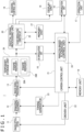
- FIG. 1 illustrates a configuration example of an imaging apparatus 1 of an embodiment.
- an imaging element 12 which includes, for example, a CMOS (Complementary Metal Oxide Semiconductor) sensor or a CCD (Charge Coupled Device) sensor, via an imaging optical system 11 to be photoelectrically converted through the imaging element 12, and an analog image signal is obtained from the imaging element 12.
- CMOS Complementary Metal Oxide Semiconductor
- CCD Charge Coupled Device
- the imaging optical system 11 includes a variety of lenses such as a zoom lens, a focus lens, and a condenser lens, an aperture mechanism, a drive mechanism for the zoom lens, and a drive mechanism for the focus lens.
- the imaging optical system 11 includes a mechanical shutter (for example, a focal plane shutter) in some cases.
- the imaging element 12 is an element including, for example, on a CMOS substrate, multiple pixels formed in a two-dimensional arrangement, a vertical scanning circuit, a horizontal scanning circuit, and an image signal output circuit, the pixels each including a photodiode (photogate), a transfer gate (shutter transistor), a switching transistor (address transistor), an amplifier transistor, a reset transistor (reset gate), and the like.
- the imaging element 12 may be either a primary-color-based or a complementary-color-based element, and an analog image signal to be obtained from the imaging element 12 is a primary-color signal of each of RGB colors or a complementary-color-based color signal.
- the imaging element 12 may include no color filter so that the analog image signal is obtained from the imaging element 12 to be a monochrome image signal.
- the analog image signal from the imaging element 12 is sampled and held on a color-signal basis by an analog signal processing unit 13 in a form of an IC (Integrated circuit), is amplitude-adjusted by AGC (Automatic Gain Control), and is converted to a digital image signal by A/D (Analog to Digital) conversion.
- IC Integrated circuit
- AGC Automatic Gain Control
- A/D Analog to Digital
- the digital image signal (hereinafter, image data) from the analog signal processing unit 13 is inputted to a temporary storage unit 26.
- imaging element 12 and the analog signal processing unit 13 or the temporary storage unit 26 in addition thereto are integrated in some cases.
- a frame memory which will be described next as the temporary storage unit 26, may be located within a stacked imaging element.
- the temporary storage unit 26 includes two frame memories 26A and 26B in this example.
- the image data from the analog signal processing unit 13 is stored alternately in the frame memory 26A and the frame memory 26B. That is, the temporary storage unit 26 stores two continuously captured image frames.
- the frames of the image data stored in the temporary storage unit 26 are sequentially outputted to a digital signal processing unit 20 on a first-in-first-out basis. That is, the data is sequentially outputted to the digital signal processing unit 20 alternately from the frame memory 26A and frame memory 26B in order of imaging.
- a live view image can be continuously displayed without a blackout even during, for example, continuous imaging.
- the digital signal processing unit 20 is configured as an image processing processor in a form of, for example, a DSP (Digital Signal Processor) or the like.
- the digital signal processing unit 20 applies various types of signal processing to the inputted image data.
- the digital signal processing unit 20 performs, as camera processes, a preparation process, a synchronization process, a YC generation process, and the like.
- the image data subjected to these various processes is subjected to file formation processing, for example, compression/coding for recording or for communication, formatting, generation/addition of metadata, and the like, to generate a file for recording or for communication.
- file formation processing for example, compression/coding for recording or for communication, formatting, generation/addition of metadata, and the like, to generate a file for recording or for communication.
- an image file in a form of JPEG, TIFF (Tagged Image File Format), GIF (Graphics Interchange Format), or the like is generated as a still image file.
- an image file may be generated in an MP4 format, which is used for recording MPEG-4-compliant moving image/voice, or the like.
- an image file may be generated as RAW image data.
- the digital signal processing unit 20 applies resolution conversion processing to the image data subjected to the various types of signal processing to generate image data whose resolution has been reduced for, for example, live view display.
- the digital signal processing unit 20 includes a flicker demodulation/correction unit 25.
- the flicker demodulation/correction unit 25 performs a process to detect a period and a peak timing of a flicker and pass information regarding the period and the peak timing to a camera control unit 21 so that flickerless imaging can be performed.
- the flicker demodulation/correction unit 25 also applies a correction process for reducing a flicker to the image data in some cases.
- a memory unit 27 refers to a buffer memory for image data.
- the image data processed by the digital signal processing unit 20 is temporarily stored in the memory unit 27 and is transferred to a display unit 15 and a recording control unit 14 or to a communication unit 16 at a predetermined timing.
- the recording control unit 14 performs recording and reproduction with respect to a recording medium in a form of, for example, a non-volatile memory.
- the recording control unit 14 performs, for example, a process to record an image file such as moving image data or still image data in a recording medium.
- the recording control unit 14 can actually take a variety of forms.
- the recording control unit 14 may be configured as a flash memory installed in the imaging apparatus 1 and a writing/reading circuit therefor.
- the recording control unit 14 may be in a form of a card recording/reproduction unit that performs, for example, recording/reproduction access with respect to a recording medium removably attached to the imaging apparatus 1, such as a memory card (portable flash memory or the like).
- the recording control unit 14 is implemented in a form installed in the imaging apparatus 1, such as an HDD (Hard Disk Drive), in some cases.
- HDD Hard Disk Drive
- the display unit 15 that is, a display unit that performs various types of display with respect to a photographer, is in a form of, for example, a display panel or a viewfinder, such as a liquid crystal panel (LCD: Liquid Crystal Display) or an organic EL (ElectroLuminescence) display, located in a housing of the imaging apparatus 1.
- LCD Liquid Crystal Display
- organic EL ElectroLuminescence
- the display unit 15 performs the various types of display on a display screen on the basis of instructions from the camera control unit 21.
- the display unit 15 causes a reproduced image of image data read from the recording medium by the recording control unit 14 to be displayed.
- the display unit 15 receives image data regarding a captured image subjected to resolution-conversion for display by the digital signal processing unit 20 and performs display, accordingly, for example, the display of a live view image.
- the display unit 15 causes a menu of various operations, an icon, a message, and the like, namely, a GUI (Graphical User Interface), to be displayed on the screen on the basis of the instructions from the camera control unit 21.
- GUI Graphic User Interface
- the communication unit 16 performs data communication or network communication with external equipment by wiredly or wirelessly. For example, the communication unit 16 sends and outputs image data (a still image file or a moving image file) or metadata to an external information processing apparatus, a display apparatus, a recording apparatus, a reproduction apparatus, or the like.
- image data a still image file or a moving image file
- metadata an external information processing apparatus, a display apparatus, a recording apparatus, a reproduction apparatus, or the like.
- the communication unit 16 is capable of performing, as a network communication unit, for example, various types of network communication over the Internet, a home network, a LAN (Local Area Network), and the like to send and receive various types of data to and from a server, a terminal, and the like on the networks.
- a network communication unit for example, various types of network communication over the Internet, a home network, a LAN (Local Area Network), and the like to send and receive various types of data to and from a server, a terminal, and the like on the networks.
- An operation unit 17 collectively refers to input devices for a user to various input operations. Specifically, the operation unit 17 refers to various operating parts (a key, a dial, a touch panel, a touch pad, and the like) located on the housing of the imaging apparatus 1.
- the operation unit 17 senses a user operation and sends a signal corresponding to the inputted operation to the camera control unit 21.
- An AE (Automatic Exposure) demodulation unit 18 performs a demodulation process for an automatic exposure adjustment from a digital image signal and supplies brightness information to the camera control unit 21.
- the camera control unit 21 includes a microcomputer (arithmetic processing apparatus) including a CPU (Central Processing Unit).
- a microcomputer central processing apparatus
- CPU Central Processing Unit
- a memory unit 19 stores information to be used by the camera control unit 21 and the like.
- the memory unit 19 illustrated in the drawing collectively refers to, for example, a ROM (Read Only Memory), a RAM (Random Access Memory), a flash memory, and the like.
- the memory unit 19 may be a memory region installed in a microcomputer chip serving as the camera control unit 21 or may include a separate memory chip.
- the camera control unit 21 controls the whole of the imaging apparatus 1 by executing a program stored in the ROM, the flash memory, or the like of the memory unit 19.
- the camera control unit 21 issues instructions on the various types of signal processing in the digital signal processing unit 20 and controls an imaging action or a recording action according to a user operation, a reproduction action for a recorded image file, and the like.
- the camera control unit 21 also performs, as automatic exposure controls based on a demodulation signal from the AE demodulation unit 18, an action control of the aperture mechanism, a control of a shutter speed of the imaging element 12, and an AGC gain control in the analog signal processing unit 13.
- the camera control unit 21 also performs an autofocus control and drive controls of a focus lens and a zoom lens according to a manual focus operation, a zoom operation, and the like.
- the camera control unit 21 is also equipped with a function as a margin-based flickerless control unit 24, which is provided by, for example, software. Accordingly, the camera control unit 21 corresponds to an imaging control apparatus that performs a margin-based flickerless control.
- the margin-based flickerless control unit 24 performs a timing control to synchronize a specific timing (for example, a timing of an exposure centroid) within an exposure duration with a peak timing on the basis of a period of a detected flicker component and a peak timing of the flicker component. That is, it performs control to cause the flickerless imaging to be performed.
- a specific timing for example, a timing of an exposure centroid
- the exposure duration refers to an effective duration of exposure using a mechanical shutter or an electronic shutter.
- the above-described timing control for the flickerless imaging is not performed.
- the margin is set as a range allowing an flickerless imaging effect to be maintained to some extent without the necessity of shifting the exposure duration.
- the flickerless imaging is an imaging action capable of reducing an influence on an image quality (a decrease in image quality) due to a flicker generated from a flicker light source.
- the RAM in the memory unit 19 is used to temporarily store data, programs, and the like as a work region for various types of data processing of the CPU of the camera control unit 21.
- the ROM and the flash memory (non-volatile memory) in the memory unit 19 are used to store an OS (Operating System) for the CPU to control each unit, an application program for various operations, firmware, various types of setting information, and the like.
- OS Operating System
- Examples of the various types of setting information include communication setting information, setting information regarding an imaging action, setting information regarding image processing, and the like.
- Examples of the setting information regarding an imaging action include exposure setting, shutter speed setting, curtain speed setting of the mechanical shutter or the electronic shutter, mode setting, and setting of the above-described margin.
- a driver unit 22 includes, for example, a motor driver for a zoom lens drive motor, a motor driver for a focus lens driver motor, a motor driver for the aperture mechanism, and the like.
- These motor drivers apply drive currents to the respective drivers in response to the instructions from the camera control unit 21, causing movements of the focus lens and the zoom lens, opening/closing of an aperture blade of the aperture mechanism, and the like to be performed.
- the shutter speed, exposure timing, and the like of the imaging element 12 are determined in accordance with a timing signal of a timing generator 23.
- the timing generator 23 outputs various timing signals to the imaging element 12 on the basis of a timing control signal from the camera control unit 21. This causes the imaging element 12 to be driven on the basis of a control by the camera control unit 21.
- arrows LV indicate a flow of live view image data
- arrows CAP indicate a flow of capture image data
- FIG. 2A is a flow of processing for displaying a live view image during standby for the release operation or a start operation for recording a moving image.
- Light entering through the imaging optical system 11 enters the imaging element 12, and the imaging element 12 outputs a photoelectrically converted image signal.
- the image signal in this case is an image signal with a relatively low resolution for live view display.
- the imaging element 12 outputs a pixel signal with a small number of pixels, from which some pixels are removed, instead of outputting all the pixels.
- the image signal from the imaging element 12 is processed by the analog signal processing unit 13, being supplied as a digital signal to the temporary storage unit 26.
- the digitized image data is stored alternately in the frame memories 26A and 26B on a frame-by-frame basis as described above. Then, the frames of the image data stored in the temporary storage unit 26 are sequentially outputted to the digital signal processing unit 20 on a first-in-first-out basis.
- the digital signal processing unit 20 performs a necessary process to generate image data for live view display and stores it in the memory unit 27.
- the display unit 15 displays an LV image stored in the memory unit 27.
- FIG. 2B illustrates the flow of data processing for recording a capture image. For example, in response to a user performing the release operation, the processing in FIG. 2B is performed.
- a release lag release time lag
- the imaging element 12 When the exposure process by the imaging element 12 is terminated, the imaging element 12 outputs a photoelectrically converted image signal to the analog signal processing unit 13.
- the image signal is a high-resolution image signal for, for example, still image recording.
- arrows LV are drawn thin and the arrows CAP are drawn thick in FIG. 2A and FIG. 2B , and the numbers of pixels of image signals are expressed by the thicknesses of the arrows.
- the image data converted to a digital signal by the analog signal processing unit 13 is processed by the digital signal processing unit 20 via the temporary storage unit 26.
- the digital signal processing unit 20 not only generates high-resolution image data for recording but also generates low-resolution image data for live view display, and stores the image data for recording and the image data for live view display in the memory unit 27 together.
- the image data for recording is transferred to the recording control unit 14 to be subjected to a recording process, and the image data for live view display is transferred to the display unit 15 to be used for live view display.
- live view display is performed in a state before the release operation for still image recording and during the release operation, but a phenomenon (blackout) of the display of a live view image getting interrupted at a timing after release may occur.
- the camera control unit 21 instructs the imaging element 12 to suspend the exposure for the live view image and change a mode. For example, the camera control unit 21 instructs the imaging element 12 to change pixels to read, resolution, and the like in order to perform capture exposure. Then, after preparations for capture exposure are made, the camera control unit 21 causes the imaging element 12 to start the capture exposure.
- an ongoing exposure for a live view image is suspended at a timing of the release operation, which causes no live view image of a corresponding frame to be displayed, resulting in a blackout.
- the blackout continues until capture exposure is performed and a frame of the live view image based on the capture exposure as illustrated in FIG. 2B is displayed.
- An example of a technique for preventing such a blackout includes a technique in which an exposure for the live view image, which is performed at a release operation timing, is not suspended. That is, by waiting for the ongoing exposure for the live view image at the release timing to be completed without being suspended and storing the resulting image data in, for example, the frame memory 26A, the live view image of the corresponding frame can be displayed.
- Another technique for preventing a blackout is also possible. For example, in response to the release operation performed while an exposure for the live view image is being performed and writing to the frame memory 26B is being performed, the exposure is suspended, and the latest image having been stored in the frame memory 26A (for example, image data regarding a frame immediately before the frame at which the exposure is suspended) is copied to the frame memory 26B. Then, the display of the live view image is continued by using the image from the frame memory 26B. At this time, the image data regarding the capture exposure is written to the frame memory 26A, and, after the completion of the capture exposure, the live view image based on the image data regarding the capture exposure is displayed.
- the latest image having been stored in the frame memory 26A for example, image data regarding a frame immediately before the frame at which the exposure is suspended
- capture exposure is repeated with a predetermined period.
- the period of capture exposure is longer than one frame period at a frame rate of a live view image
- coma-to-coma exposure is performed one or multiple times between capture exposures.
- exposure actions such as “capture exposure,” “coma-to-coma exposure,” “coma-to-coma exposure,” “capture exposure,” “coma-to-coma exposure,” “coma-to-coma exposure,” ... are repeated until the termination of continuous shooting.
- a control similar to the above-described control at the release timing is performed in switching from coma-to-coma exposure to capture exposure, which makes it possible to display a live view image during continuous shooting without causing a blackout.
- FIG. 3 illustrates a configuration example of a part of the digital signal processing unit 20, in particular, a configuration example for explaining a location of the flicker demodulation/correction unit 25.
- FIG. 3 is a configuration example of a primary-color-based system.
- the imaging optical system 11 in FIG. 1 includes a photodecomposition system that splits light from an object into colored lights of RGB colors, and the imaging element 12 is in a form of a three-plate system including respective imaging elements for RGB colors, or the imaging element 12 is in a form of a single-plate system including a single imaging element including respective color filters of RGB colors repeatedly arranged on a light entrance surface in sequence in a screen horizontal direction on a pixel-by-pixel basis.
- a black level of an inputted RGB primary color signal is clamped at a predetermined level by a clamp circuit 41 and a gain of the clamped RGB primary color signal is adjusted in accordance with an exposure amount by a gain adjustment circuit 42.
- Flicker demodulation/correction units 25R, 25G, and 25B each detect a period of a flicker component and a peak timing of the flicker component for the purpose of the flickerless imaging.
- the flicker demodulation/correction units 25R ,25G, and 25B are also each capable of a flicker correction process to reduce a flicker component in an RGB primary color signal.
- RGB primary color signals passing through the flicker demodulation/correction units 25R ,25G, and 25B are subjected to a white-balance adjustment by a white balance adjustment circuit 43, gradations of the white-balance-adjusted RGB primary color signals are converted by a gamma correction circuit 44, and a luminance signal Y and color-difference signals R-Y and B-Y to be outputted are generated from the gamma-corrected RGB primary color signals by a synthesis matrix circuit 45.
- the luminance signal Y is usually generated after all the processes for the RGB primary color signal are terminated as illustrated in FIG. 3 . Accordingly, reducing a flicker component in the RGB primary color signal during the processes for the RGB primary color signal makes it possible to sufficiently reduce both flicker components in each color component and a luminance component.
- the flicker demodulation/correction unit 25 may be located on a luminance-signal-Y output side of the synthesis matrix circuit 45 to detect and reduce a flicker component in the luminance signal Y.
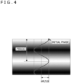
- a flicker component as in FIG. 4 is generated during the occurrence of a flicker phenomenon. It should be noted that scanning is assumed to be performed from an upper side (upper portion of the screen) toward a lower side (lower portion of the screen) in FIG. 4 .
- an exposure timing is different for each horizontal line, which causes an amount of light received to change depending on the horizontal line. This results in the existence of a horizontal line where the image signal has a larger value than an average value and a horizontal line where the image signal has a smaller value than the average value as in FIG. 4 even though illumination with a fluorescent lamp is spatially even.
- a peak where a flicker component amplitude of the flicker component
- the flicker component reaches the maximum on a horizontal line offset by an amount corresponding to 3/5 of the total number of lines contained in a single image.
- a flicker component can thus be represented by a sin function (sinusoidal wave) having an amplitude, a period, and an initial phase as illustrated in FIG. 4 .
- the initial phase refers to a phase of the head line.
- a phase of each horizontal line changes depending on the frame. That is, a horizontal line where the image signal has a larger value than the average value and a horizontal line where the image signal has a smaller value than the average value change on a frame-by-frame basis.
- the next frame has a sinusoidal wave with a different initial phase. For example, assuming that a flicker caused by a fluorescent lamp occurs at 100 Hz and a frame rate is 60 fps, five periods of the flicker of a fluorescent lamp correspond to three frames in terms of time. Thus, the initial phase becomes the same every three frame. A flicker component thus varies according to the horizontal line and the frame.
- Such an imaging enabling reducing an influence of a flicker appearing in an image is the flickerless imaging.
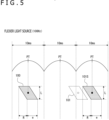
- FIG. 5 illustrates an amplitude of a 10-ms period of a flicker light source.
- An exposure action 100 is also illustrated.
- the exposure action 100 is schematically illustrated in a form of a parallelogram defined by the number of vertical lines L, a duration required for reading effective pixels from the head to the end (curtain speed) R, and an exposure duration (shutter speed) e.
- the exposure duration is shorter than a single period of a flicker and a timing of the exposure centroid matches a peak timing PT of the flicker.
- the timing of the exposure centroid refers to a timing corresponding to substantially the middle of an exposure duration of substantially a middle line in a vertical direction of the imaging element.
- Such an exposure performed at a timing synchronous with the peak timing PT makes it possible to obtain an image less influenced by a flicker.
- a timing of a next exposure action 101 becomes as illustrated due to a period of the exposure action.
- a period of a flicker and a frame period corresponding to a frame rate of a captured image do not match as described above, and therefore, even though the exposure action 100 is provided at a time point, exposure may be performed during a duration when an amplitude of the flicker is significantly reduced, such as a part corresponding to a valley of a flicker waveform, at another time point as exemplified by the exposure action 101. In this case, a relatively large influence of the flicker is seen in an image.
- the timing of the exposure action 101 is delayed to synchronize the timing of the exposure centroid with the peak timing PT of the flicker as exemplified by an exposure action 101S.
- Such imaging accompanied with a control of an exposure timing is referred to as flickerless imaging.
- the camera control unit 21 (the margin-based flickerless control unit 24) to sense a frequency and a peak timing of a flicker.
- the flicker demodulation/correction unit 25 (25R, 25G, and 25B) of the digital signal processing unit 20 performs flicker demodulation, detects the peak timing and the frequency, and notifies the camera control unit 21 (the margin-based flickerless control unit 24) of the peak timing and the frequency.
- the flicker demodulation/correction unit 25 also performs, by way of example, flicker correction to reduce a flicker component in image data in addition to the flicker demodulation as described above.
- an inputted image signal refers to the RGB primary color signal or the luminance signal inputted to the flicker demodulation/correction unit 25 (25R, 25G, and 25B) as in FIG. 3
- an outputted image signal refers to an RGB primary color signal or a luminance signal processed by the flicker demodulation/correction unit 25 (25R, 25G, and 25B) .
- the flicker demodulation/correction unit 25 in FIG. 6 includes, for example, a normalized integrated value computing block 30, a DFT (discrete Fourier transform) block 50, a flicker generation block 55, a frequency estimation/peak detection block 60, and an arithmetic block 65.
- a normalized integrated value computing block 30 includes, for example, a DFT (discrete Fourier transform) block 50, a flicker generation block 55, a frequency estimation/peak detection block 60, and an arithmetic block 65.
- the normalized integrated value computing block 30 includes an integration block 31, an integrated value retention block 32, an average value calculation block 33, a difference calculation block 34, and a normalization block 35.
- the integration block 31 computes an integrated value Fn(y) by integration across a single line in a screen-horizontal direction of an inputted image signal In' (x, y).
- the computed integrated value Fn(y) is stored and retained in the integrated value retention block 32 for the purpose of flicker detection for a subsequent frame.
- the integrated value retention block 32 is configured to be able to retain integrated values for frames necessary for processing (for example, for two frames).
- the average value calculation block 33 computes an average value AVE[Fn(y)] of, for example, three integrated values Fn(y), Fn_1(y), and Fn_2(y). It should be noted that Fn_1(y) is an integrated value Fn_1(y) of the same line in a last frame, Fn_2(y) is an integrated value Fn_2(y) of the same line in a second last frame, and these integrated values are values read from the integrated value retention block 32.
- the difference calculation block 34 computes a difference between the integrated value Fn(y) supplied from the integration block 31 and the integrated value Fn_1(y) of the last frame supplied from the integrated value retention block 32.
- a difference value Fn(y) - Fn_1(y) from which an influence of an object is sufficiently removed, clearly indicates how a flicker component (a flicker coefficient) is as compared with the integrated value Fn(y).
- the normalization block 35 performs a normalization process including dividing the difference value Fn(y) - Fn_1(y) from the difference calculation block 34 by the average value AVE[Fn(y)] from the average value calculation block 33 to compute a normalized difference value gn(y).
- the DFT block 50 applies discrete Fourier transform to data regarding the normalized difference value gn(y) from the normalization block 35, the data corresponding to a single waveform (L line) of a flicker. An amplitude ⁇ m and an initial phase ⁇ mn of each subsequent flicker component are thus estimated. It should be noted that the initial phase ⁇ mn is retained in association with a counter generated in the imaging apparatus 1 every predetermined time (for example, every 0.5 ⁇ s (microseconds)).
- the initial phase ⁇ mn calculated by the DFT block 50 is supplied to the frequency estimation/peak detection block 60.
- the frequency estimation/peak detection block 60 estimates at least a frequency of a flicker component (light source), in other words, a period of the flicker component, on the basis of the inputted initial phase ⁇ mn and, further, detects a timing of a peak of the flicker component. For example, the frequency estimation/peak detection block 60 estimates the frequency of the flicker component from a time lag based on a frame rate and a phase difference of the initial phase ⁇ mn. Further, the frequency estimation/peak detection block 60 detects the timing of the peak of the flicker component from, for example, respective counters associated with the initial phase ⁇ mn in a first frame and the present initial phase ⁇ mn.
- the initial phase ⁇ mn is 60 degrees
- a timing of the appearance of a peak (for example, 90 degrees) of a flicker component which can be approximated by a sinusoidal wave, by using a time interval between the counters.
- the peak of the flicker component is a spot where the amplitude of the flicker component reaches the maximum as described above.
- the camera control unit 21 (the margin-based flickerless control unit 24) is notified of information obtained by the frequency estimation/peak detection block 60 in this manner.
- the camera control unit 21 can perform the above-described timing control of the imaging element as the flickerless imaging.
- the features of a flicker component i.e., the period, the peak timing, and the like of the flicker component can be detected on the basis of a captured image without the necessity of a separate sensor or the like. This makes it possible to prevent an increase in cost due to an increase in the number of parts.
- the imaging apparatus can be downsized. It should be noted that the processing for obtaining the features of a flicker component is not limited to the method described above and a known method is applicable.
- the flicker demodulation/correction unit 25 can perform the flicker correction to reduce a flicker component generated in an image signal.
- a flicker coefficient Fn(y) is computed from the estimation values of ⁇ m and ⁇ mn from the DFT block 50.
- the arithmetic block 65 then adds 1 to the flicker coefficient ⁇ n(y) from the flicker generation block 53 and performs an inverse gain multiplication process to divide the inputted image signal In'(x, y) by a resulting sum [1 + ⁇ n(y)].
- the configuration in the FIG. 6 without the arithmetic block 65 and the flicker generation block 55 may be provided as a flicker detection unit.
- This control is intended to reduce the number of times when a live view image is caused to become a non-smooth moving image due to the flickerless imaging in a case where, for example, continuous imaging is performed while the liver view image is being displayed.
- FIG. 7 illustrates a flicker amplitude of a 121-Hz light source and an exposure action for capturing an image at 20 fps under the light source.
- This exemplifies an action during continuous imaging as an example, illustrating a case where a capture exposure CPE is performed multiple times and two coma-to-coma exposures IE1 and IE2 are performed between one of the capture exposures CPE and the next capture exposure CPE.
- the exposure action for a single frame is illustrated in a form of a parallelogram determined by the curtain speed, the exposure time, and the number of horizontal lines as in FIG. 5 . It should be noted that a parallelogrammatic shape in the drawing is merely schematic and is not intended to strictly indicate the curtain speed, the exposure time, and the number of lines.
- a synchronization signal SensV is a synchronization signal responsive to the imaging action of the imaging element 12 and a timing thereof is set variable through a control by the camera control unit 21.
- a synchronization signal SysV is a synchronization signal responsive to the display action of the display unit 15 and is provided at a vertical timing at a predetermined frame rate (in this case, 20 fps). For a live view image, an image of each frame is to be displayed at timings according to the synchronization signal SysV.
- a user performs an operation for continuous imaging, causing a first capture exposure CPE to be performed at or after a time point t10.
- the timing control for the first capture exposure CPE is performed to cause an exposure centroid timing WT to match the peak timing PT of a flicker.
- the coma-to-coma exposures IE1 and IE2 are performed at timings according to a 20-fps frame rate.
- an LV image CPP based on the capture exposure CPE is displayed in a frame after the termination of the capture exposure CPE, an LV image IP1 based on the coma-to-coma exposure IE1 is displayed in a next frame, and an LV image IP2 based on the coma-to-coma exposure IE2 is displayed in a second next frame.
- a timing when the next capture exposure CPE is to be performed comes. However, if the current period is kept without change, the timing of the exposure centroid will fail to match the peak timing PT. Accordingly, a timing control TS is performed to delay a start timing of the capture exposure CPE. This means that the synchronization signal SensV is delayed.
- the capture exposures CPE at or after the time point t12 also corresponds to the flickerless imaging with the exposure centroid timing WT matching the peak timing PT.
- the coma-to-coma exposures IE1 and IE2 are performed at the timings according to the 20-fps frame rate.
- the capture exposure CPE is delayed by the timing control TS, which causes the same LV image IP2 to be displayed continuously during a duration of two frames. This is because the capture exposure CPE is not terminated at a time point of the start of the second frame at or after the time point t12.
- the flickerless imaging is also achieved with the exposure centroid timing WT of the capture exposure CPE matching the peak timing PT by performing the timing control TS to delay the synchronization signal SensV.
- the continuous display of the same LV image IP2 during a duration of two frames occurs due to the delay of the capture exposure CPE.
- data regarding multiple still images continuously shot obtained by the capture exposures CPE can be provided as images less influenced by a flicker.
- the same image continues as the live view image at or after the time point t12 or at or after the time point t14 described above.
- each of a time lag from the capture exposure CPE to the LV image CPP based thereon, a time lag from the coma-to-coma exposure IE1 to the LV image IP1, and a time lag from the coma-to-coma exposure IE2 to the LV image IP2 is latency for the live view image, and, in a case of the example in the drawing, the latency varies (an inclination of an arrow from an exposure termination timing to a display start timing is not constant).
- a motion of a live view image is recognized as not being smooth by a user.
- the flickerless imaging is performed in a manner to reduce an influence of a flicker appearing in an image for recording and to prevent the smoothness of the live view image from being impaired as much as possible.
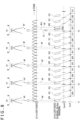
- FIG. 8 illustrates a flicker of the 121-Hz light source, the capture exposures CPE, the coma-to-coma exposures IE1 and IE2, the synchronization signal SensV, the synchronization signal SysV, and the LV images CPP, IP1, and IP2 that are respective frames of the live view image.
- a user performs a continuous imaging operation, causing a first capture exposure CPE to be performed at or after a time point t1.
- the first capture exposure CPE is subjected to a timing control to cause an exposure centroid timing WT to match the peak timing PT of a flicker as in the case in FIG. 7 .
- the coma-to-coma exposures IE1 and IE2 are performed at the timings according to the 20-fps frame rate.
- an LV image CPP based on the capture exposure CPE is displayed in a frame after the termination of the capture exposure CPE, an LV image IP1 based on the coma-to-coma exposure IE1 is displayed in a next frame, and an LV image IP2 based on the coma-to-coma exposure IE2 is displayed in a second next frame.
- a timing when the next capture exposure CPE is to be performed comes.
- the timing when the next capture exposure CPE is to be performed is assumed to be a timing with the exposure period kept. This means that it is a timing when a duration length from a start timing of an exposure duration of the previous coma-to-coma exposure IE2 to a start timing of an exposure duration of the current capture exposure CPE and a duration length from a start timing of an exposure duration of the coma-to-coma exposure IE1 before the previous one to the start timing of the exposure duration of the previous coma-to-coma exposure IE2 are the same.
- the exposure centroid timing WT does not match the peak timing PT.
- an offset amount of the exposure centroid timing WT from the peak timing PT falls within a range of a margin M as illustrated in the enlarged diagram.
- the margin M is set as a range allowing an image to be evaluated as not being influenced by a flicker even though the exposure centroid timing WT is offset from the peak timing PT.
- the timing control to delay the start timing of the capture exposure CPE to cause the exposure centroid timing WT to match the peak timing PT is not performed. This means that a period of the 20-fps frame rate of the synchronization signal SensV is maintained and the capture exposure CPE is performed without change.
- coma-to-coma exposures IE1 and IE2 are then similarly performed at the timings according to the 20-fps frame rate.
- An offset amount of the exposure centroid timing WT from the peak timing PT falls within the range of the margin M also at each of a time point t3 and a time point t4 as illustrated in the enlarged diagram. Accordingly, the timing control to delay the start timing of the capture exposure CPE to cause the exposure centroid timing WT to match the peak timing PT is not performed. This means that the capture exposure CPE and the coma-to-coma exposures IE1 and IE2 are performed with the period of the 20-fps frame rate maintained.
- an offset amount of an exposure centroid timing WTd from the peak timing PT is assumed to exceed the range of the margin M.
- the timing control TS that delays the start timing to cause the exposure centroid timing WT to match the peak timing PT is performed and the capture exposure CPE is performed.
- timing control TS as flickerless imaging is to be performed in accordance with a relation between the offset amount of the exposure centroid timing WT from the peak timing PT and the margin M.
- the LV images CPP, IP1, and IP2 are sequentially displayed at a constant frame rate and a latency before the time point t5, enabling a smooth moving image to be displayed.
- the user-viewing frame rate and the latency vary due to the execution of the timing control TS.
- the number of times when such a state occurs can be reduced as compared with the action in FIG. 7 , and thus a user can be less likely to feel impairment of the smoothness of the live view image as a moving image.
- FIG. 9 illustrates a processing example of the control unit 24 during a duration when the continuous imaging operation is performed, for example, a duration when a user is kept pressing the release button as a continuous shooting mode.
- Step S101 the control unit 24 proceeds from Step S101 to Step S102, performing the timing control as the flickerless imaging for the first capture exposure CPE.
- the exposure timing is controlled to cause the exposure centroid timing WT to match the peak timing PT.
- Step S103 the control unit 24 causes the digital signal processing unit 20 to perform still image recording and the image processing for live view display based on the capture exposure CPE.
- Step S104 the control unit 24 proceeds from Step S104 to Step S105.
- the control unit 24 proceeds from Step S105 to Step S108 when the timing of the capture exposure CPE is based on the synchronization signal SensV and otherwise proceeds from Step S105 to Step S106.
- the control unit 24 performs the timing control for the coma-to-coma exposure IE1 in Step S106.
- the coma-to-coma exposure IE1 with a period based on the synchronization signal SensV kept is performed, and, in Step S107, the digital signal processing unit 20 is caused to perform image processing for live view display according to the coma-to-coma exposure IE1.
- control unit 24 causes the coma-to-coma exposure IE2 and the image processing for live view display according thereto to be performed.
- Step S105 the control unit 24 proceeds from Step S105 to Step S108.
- the control unit 24 computes an offset amount between the exposure centroid timing WT resulting from performing the capture exposure CPE at a timing with the period based on the synchronization signal SensV being maintained and the peak timing PT.
- the control unit 24 then makes a comparison between the offset amount and the margin M in Step S109.
- control unit 24 performs the timing control as the flickerless imaging in Step S110, causing the exposure centroid timing WT to match peak timing PT.
- Step S111 the control unit 24 proceeds to Step S111, causing the capture exposure CPE to be performed with the current exposure period being maintained.
- Step S103 to Step S111 are repeated until the continuous imaging operation is determined to be terminated in Step S104.
- the above example is described as an action during continuous imaging but is applicable even to live view display prior to capturing an moving image or a single still image in addition to during continuous imaging, and, in a case where the flickerless imaging is to be performed, exposure is performed with the period unchanged (consequently, the peak timing PT and the exposure centroid timing WT are offset from each other) as long as an offset between the peak timing PT and the exposure centroid timing WT falls within the range of the margin M, which makes it possible to achieve smooth live view display.
- the margin M only has to be set in accordance with an amplitude or a period of a flicker, or only has to be set as a range allowing an offset amount between a predetermined timing of an exposure duration, such as the exposure centroid timing WT, and the peak timing PT to be evaluated as that no influence of the flicker appears in an image.
- the imaging apparatus 1 only has to include a fixed single set value as such a margin M. For example, it is only sufficient if a single set value is provided as the margin M applicable to various imaging modes or the like.
- FIG. 10 illustrates a relation between a curtain speed and a margin.
- Exposure actions 71, 72, and 73 at a curtain speed R1 are schematically indicated by slanted lines, and respective exposure centroids thereof are referred to as exposure centroid timings WT71, WT72, and WT73.
- the exposure actions 71, 72, and 73 do not mean that exposure is to be performed for three times but exemplify patterns different in exposure duration with respect to a flicker period.
- FIG. 10 illustrates that, in a case where the curtain speed is R1, performing exposure during a duration within a range defined from the exposure action 71 to the exposure action 73 causes the amplitude value of a flicker during the exposure duration to become equal to or more than the threshold th1. This means that an image is hardly influenced by a flicker irrespective of which one of the exposure centroid timings WT71, WT72, and WT73 is the exposure centroid timing WT.
- the margin M can be set as a margin M1 illustrated before and after the peak timing PT.
- exposure actions 81, 82, and 83 at a curtain speed R2 are schematically indicated by slanted lines, and respective exposure centroids thereof are referred to as exposure centroid timings WT81, WT82, and WT83.
- the margin M can be set as a margin M2 illustrated before and after the peak timing PT.
- the margin M it is possible to set the margin M according to the curtain speed. Accordingly, in a case where the curtain speed changes due to a change of the imaging mode or replacement of a replacement lens, it is desirable that the margin M be also changed.
- the margin M can be modulated as follows with reference to, for example, the margin M1 in FIG. 10 .
- M 2 M 1 ⁇ R 2 ⁇ R 1 2 R 1 ⁇ R 2
- the margin M can also be dynamically set according to an exposure shortfall in a case where the peak timing PT is caused to match the exposure centroid timing WT.
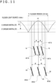
- FIG. 11 illustrates that, in a flicker period T, the margin M is set on the assumption of, as an exposure shortfall from the peak timing PT, an exposure shortfall D that can be evaluated as that no influence of a flicker appears in an image.
- the exposure shortfall is, for example, a difference between an exposure amount from a flicker light source obtainable when the peak timing PT and the exposure centroid timing WT match each other and an exposure amount from the flicker light source obtainable when the exposure centroid timing WT does not match the peak timing PT.
- Exposure actions 74, 75, and 76 at a curtain speed R illustrated each refer to exposure capable of maintaining an image quality to a certain extent on the assumption of the exposure shortfall D.
- the correctable exposure shortfall D is set within an allowable range in view of a degree of image quality degradation due to the gain process.
- the exposure shortfall is set as illustrated as an exposure shortfall D'.
- the degree of image quality degradation due to the gain process differs with a performance of the imaging element 12, an imaging mode, or the like.
- a required image quality also differs with a product/model as a camera. Accordingly, a larger exposure shortfall D' can be set in some cases.
- exposure may be performed during a duration as illustrated as exposure actions 84, 85, and 86 at the same curtain speed R. This means that it is only sufficient if a margin M' is set to cause a range of the exposure centroid timings WT84, WT85, and WT86 to be covered.
- the margin M may be set variable in accordance with a size of an image read from the imaging element 12.
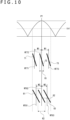
- FIG. 12 illustrates a case where a full size (36.0 mm ⁇ 24.0 mm) is to be read from the imaging element 12 and a case where an APS-C size (22.4 mm ⁇ 15.0 mm) is to be read.
- a flicker amplitude value that can be evaluated as that no influence of a flicker appears in an image is assumed to be the threshold th1 or more.
- Exposure actions 77, 78, and 79 for full-size reading and exposure actions 87, 88, and 89 for the APS-C size have different curtain speeds, such as the curtain speed R1 and the curtain speed R2 illustrated, due to a difference in the number of pixels (the number of lines) resulting from a difference in reading range within a screen.
- the margin M1 which covers exposure centroid timings WT77, WT78, and WT79, be applied for the full-size reading and the margin M2, which covers exposure centroid timings WT87, WT88, and WT89, be applied for the APS-C reading.
- the margin M varies with an allowable degree of an influence of a flicker.
- the margin M may be widened for a duration when only exposure for a live view image is performed (i.e., a duration when no capture exposure is performed) during standby for release or the like to relax the flickerless control. This makes it possible to reduce opportunities for the above-described timing control TS to be performed for exposure for a live view image, enabling further improving the smoothness of the live view image as a moving image.
- the margin M may be changed according to whether or not the flicker correction is to be performed.
- the imaging apparatus 1 or the imaging control apparatus (the camera control unit 21) of the above-described embodiment the following effects can be enjoyed.
- the imaging apparatus 1 or the camera control unit 21 of the embodiment includes a control unit (the margin-based flickerless control unit 24) that performs the margin-based flickerless control where the timing control TS is performed, on the basis of the period of a detected flicker component and the peak timing PT of the flicker component, to synchronize a specific timing within an exposure duration with the peak timing PT, and where the timing control TS is not performed as long as an offset amount between the specific timing and the peak timing PT falls within the set margin M.
- a control unit the margin-based flickerless control unit 24
- a release lag may be reduced.
- margin-based flickerless control is beneficial not only for continuous imaging but also for live view display prior to the start of capturing a still image or live view display in a motion mode or the like. That is, even when exposure for live view display is performed, while the timing control to cause the timing of exposure to match the peak of a flicker, the timing control is not performed to cause the timing to match the peak as long as an offset amount falls within the margin. This makes it possible to reduce the number of times when the user-viewing frame rate of image data based on exposure changes and when the latency to the output of an image changes, and consequently, to display a smooth live view image.
- the margin-based flickerless control unit 24 performs the timing control for the first capture exposure CPE after the start of continuous imaging, and, for the second and subsequent capture exposures CPE, does not perform the timing control TS as long as an offset amount of the specific timing falls within the margin M but performs the timing control TS unless the offset amount of the specific timing falls within the margin M (see FIG. 8 and FIG. 9 ).
- the specific timing in the exposure duration (for example, the exposure centroid timing WT) is caused to match the peak timing PT of a flicker, which makes it possible to obtain image data less influenced by the flicker.
- the timing control TS is performed for a minimum number of times as needed, which makes it possible to reduce an influence of the flicker on each of images captured by continuous shooting and to improve the smoothness of the live view image.
- the exposure period on the assumption that the exposure period is kept to cause a duration length from the start timing of the previous exposure duration to the start timing of the current exposure duration and a duration length from the start timing of one before the previous exposure duration to the start timing of the previous exposure duration to be the same, it is determined whether or not the offset amount of the specific timing in the current exposure duration from the peak timing PT falls within the margin M.
- timing control TS it is determined whether or not the timing control TS is to be performed according to how much the exposure centroid timing WT is offset from the peak timing PT with the exposure period kept.
- control is performed to cause a state where the exposure period is kept constant to continue as long as possible. This makes it possible to reduce, for example, changes of the user-viewing frame rate and the latency of a live view image.
- the above-described specific timing is the exposure centroid timing WT. This means that it is a timing corresponding to substantially the middle of an exposure duration of substantially a middle line in the vertical direction of the imaging element.
- the timing substantially in the middle of the frame is caused to match the peak timing of a flicker, which makes it possible to enjoy a flickerless effect in the most optimal manner.
- the exposure centroid is not necessarily precise. Accordingly, the specific timing does not necessarily precisely match the exposure centroid.
- the margin M may be set to cause the offset amount from the peak timing PT to be determined with reference to the start timing or the termination timing of exposure.
- the margin in a case where a margin is set in accordance with a curtain speed, the margin can be increased for a high curtain speed, whereas the margin can be reduced for a slow curtain speed.
- changes of the user-viewing frame rate and the latency can be reduced as much as possible in accordance with the curtain speed and even the quality of a live view image can be improved.
- control can be applied in respective states suitable to modes different in curtain speed, for example, modes for different image sizes such as the full size and the APS-C size.
- the margin can be dynamically increased as much as possible within a range evaluated as that no influence of a flicker appears according to the exposure shortfall.
- changes of the user-viewing frame rate and the latency can be reduced as much as possible, and even the quality of a live view image can be improved.
- the margin M is changed according to whether or not the flicker correction to correct image data by using a gain is to be performed, the gain being set for each line on the basis of the period of a detected flicker component and the peak timing of the flicker component.
- the margin is increased, which makes it possible to further reduce the number of times when the user-viewing frame rate and the latency change. This also leads to an improvement in quality of a live view image.
- the margin M is set according to the number of pixels read from the imaging element.
- the curtain speed also changes, and therefore, it is favorable that the margin be set in accordance with the curtain speed.
- the margin be set according to all-pixel reading/partially skip reading or the like instead of full size/APSC.
- the margin is set according to whether or not the exposure is for an image to read.
- an image used merely for live view display has a relatively large degree of allowance against an influence of a flicker.
- the margin be set variable according to whether or not the exposure is for an image to record.
- the number of times when the user-viewing frame rate and the latency change can be further reduced by increasing the margin during live view display, which leads to an improvement in quality of a live view image.
- the margin is set narrower than that during a duration when no exposure for an image to record is performed, which is suitable for improving the quality of the image to record.
- a program of the embodiment is a program that causes an arithmetic processing apparatus such as a CPU to perform the above-described margin-based flickerless control.
- the program of the embodiment is a program that causes an arithmetic processing apparatus to carry out a control, i.e., the above-described margin-based flickerless control, to perform, on the basis of the period of a detected flicker component and the peak timing PT of the flicker component, the timing control TS to synchronize the specific timing (for example, the exposure centroid timing WT) within the exposure duration with the peak timing PT, and not to perform the timing control TS as long as an offset amount of the specific timing falls within the margin M, which is set as an offset allowance from the peak timing PT.
- a control i.e., the above-described margin-based flickerless control
- the above-described camera control unit 21 can be implemented by an arithmetic processing apparatus such as a microcomputer.
- HDD Compact Disc Read Only Memory
- MO Magnetic Optical
- DVD Digital Versatile Disc
- Blu-ray Disc registered trademark
- a magnetic disk a semiconductor memory, or a memory card.
- a removable recording medium can be provided as what is called package software.
- Such a program can be downloaded from a download site over a network such as LAN (Local Area Network) or the Internet in addition to being installed in a personal computer or the like from the removable recording medium.
- LAN Local Area Network
- the Internet in addition to being installed in a personal computer or the like from the removable recording medium.
Landscapes
- Engineering & Computer Science (AREA)
- Multimedia (AREA)
- Signal Processing (AREA)
- Studio Devices (AREA)
Applications Claiming Priority (2)
| Application Number | Priority Date | Filing Date | Title |
|---|---|---|---|
| JP2021002695 | 2021-01-12 | ||
| PCT/JP2021/043165 WO2022153682A1 (ja) | 2021-01-12 | 2021-11-25 | 撮像装置、撮像制御方法、プログラム |
Publications (2)
| Publication Number | Publication Date |
|---|---|
| EP4280590A1 true EP4280590A1 (en) | 2023-11-22 |
| EP4280590A4 EP4280590A4 (en) | 2024-07-17 |
Family
ID=82447155
Family Applications (1)
| Application Number | Title | Priority Date | Filing Date |
|---|---|---|---|
| EP21919573.2A Pending EP4280590A4 (en) | 2021-01-12 | 2021-11-25 | IMAGING DEVICE, IMAGING CONTROL METHOD AND PROGRAM |
Country Status (5)
| Country | Link |
|---|---|
| US (1) | US20240031686A1 (ja) |
| EP (1) | EP4280590A4 (ja) |
| JP (1) | JPWO2022153682A1 (ja) |
| CN (1) | CN116806430A (ja) |
| WO (1) | WO2022153682A1 (ja) |
Family Cites Families (4)
| Publication number | Priority date | Publication date | Assignee | Title |
|---|---|---|---|---|
| JP2008252401A (ja) * | 2007-03-29 | 2008-10-16 | Fujifilm Corp | 撮像システム、撮像方法、および撮像プログラム |
| JP6220225B2 (ja) * | 2013-10-30 | 2017-10-25 | キヤノン株式会社 | 撮像装置、撮像装置の制御方法、プログラム、及び記録媒体 |
| JP6370134B2 (ja) * | 2014-07-02 | 2018-08-08 | キヤノン株式会社 | 撮像装置、その制御方法、および制御プログラム |
| JPWO2017217137A1 (ja) * | 2016-06-15 | 2019-04-11 | ソニー株式会社 | 撮像制御装置、撮像制御方法およびプログラム |
-
2021
- 2021-11-25 WO PCT/JP2021/043165 patent/WO2022153682A1/ja active Application Filing
- 2021-11-25 JP JP2022575104A patent/JPWO2022153682A1/ja active Pending
- 2021-11-25 CN CN202180089315.6A patent/CN116806430A/zh active Pending
- 2021-11-25 US US18/260,365 patent/US20240031686A1/en active Pending
- 2021-11-25 EP EP21919573.2A patent/EP4280590A4/en active Pending
Also Published As
| Publication number | Publication date |
|---|---|
| WO2022153682A1 (ja) | 2022-07-21 |
| US20240031686A1 (en) | 2024-01-25 |
| CN116806430A (zh) | 2023-09-26 |
| JPWO2022153682A1 (ja) | 2022-07-21 |
| EP4280590A4 (en) | 2024-07-17 |
Similar Documents
| Publication | Publication Date | Title |
|---|---|---|
| US10972677B2 (en) | Imaging control apparatus and imaging control method | |
| JP4173457B2 (ja) | 撮影装置及びその制御方法 | |
| US10771713B2 (en) | Imaging control device, imaging control method, and program | |
| US9560265B2 (en) | Image processing apparatus, image processing method, image processing program, and imaging apparatus | |
| JP6911850B2 (ja) | 画像処理装置、画像処理方法およびプログラム | |
| JP2010062802A (ja) | 撮像装置、撮像方法およびその方法を実行させるためのプログラムを記録したコンピュータ読み取り可能な記録媒体 | |
| EP4280590A1 (en) | Imaging device, imaging control method, and program | |
| US11356611B2 (en) | Image capture apparatus and control method thereof | |
| WO2022172639A1 (ja) | 撮像装置、撮像方法、プログラム | |
| JP6225463B2 (ja) | 撮像装置、撮像方法および記録媒体 | |
| JP4221051B2 (ja) | 撮影装置及びその制御方法 | |
| JP4397766B2 (ja) | 撮像装置 | |
| US20240314422A1 (en) | Imaging device, imaging control method, and program | |
| JP4310755B2 (ja) | 撮影装置及びその制御方法 | |
| JP6800693B2 (ja) | 撮像装置及び撮像装置の駆動方法 | |
| JP2008236808A (ja) | 撮影装置及びその制御方法 | |
| JP2005159976A (ja) | 撮像装置 | |
| JP5720382B2 (ja) | 撮像装置 | |
| JP5504905B2 (ja) | 撮像装置 | |
| JP2006050308A (ja) | 撮像装置 | |
| JPH0646320A (ja) | ビデオカメラによる撮影方法およびビデオカメラ |
Legal Events
| Date | Code | Title | Description |
|---|---|---|---|
| STAA | Information on the status of an ep patent application or granted ep patent |
Free format text: STATUS: THE INTERNATIONAL PUBLICATION HAS BEEN MADE |
|
| PUAI | Public reference made under article 153(3) epc to a published international application that has entered the european phase |
Free format text: ORIGINAL CODE: 0009012 |
|
| STAA | Information on the status of an ep patent application or granted ep patent |
Free format text: STATUS: REQUEST FOR EXAMINATION WAS MADE |
|
| 17P | Request for examination filed |
Effective date: 20230814 |
|
| AK | Designated contracting states |
Kind code of ref document: A1 Designated state(s): AL AT BE BG CH CY CZ DE DK EE ES FI FR GB GR HR HU IE IS IT LI LT LU LV MC MK MT NL NO PL PT RO RS SE SI SK SM TR |
|
| DAV | Request for validation of the european patent (deleted) | ||
| DAX | Request for extension of the european patent (deleted) | ||
| REG | Reference to a national code |
Ref country code: DE Ref legal event code: R079 Free format text: PREVIOUS MAIN CLASS: H04N0005235000 Ipc: H04N0023667000 |
|
| A4 | Supplementary search report drawn up and despatched |
Effective date: 20240617 |
|
| RIC1 | Information provided on ipc code assigned before grant |
Ipc: H04N 23/80 20230101ALI20240611BHEP Ipc: H04N 23/745 20230101ALI20240611BHEP Ipc: H04N 23/667 20230101AFI20240611BHEP |