EP4279828A1 - Air conditioner - Google Patents
Air conditioner Download PDFInfo
- Publication number
- EP4279828A1 EP4279828A1 EP22755804.6A EP22755804A EP4279828A1 EP 4279828 A1 EP4279828 A1 EP 4279828A1 EP 22755804 A EP22755804 A EP 22755804A EP 4279828 A1 EP4279828 A1 EP 4279828A1
- Authority
- EP
- European Patent Office
- Prior art keywords
- primary filter
- filter
- air
- irradiator
- air passage
- Prior art date
- Legal status (The legal status is an assumption and is not a legal conclusion. Google has not performed a legal analysis and makes no representation as to the accuracy of the status listed.)
- Withdrawn
Links
Images




Classifications
-
- F—MECHANICAL ENGINEERING; LIGHTING; HEATING; WEAPONS; BLASTING
- F24—HEATING; RANGES; VENTILATING
- F24F—AIR-CONDITIONING; AIR-HUMIDIFICATION; VENTILATION; USE OF AIR CURRENTS FOR SCREENING
- F24F8/00—Treatment, e.g. purification, of air supplied to human living or working spaces otherwise than by heating, cooling, humidifying or drying
- F24F8/20—Treatment, e.g. purification, of air supplied to human living or working spaces otherwise than by heating, cooling, humidifying or drying by sterilisation
- F24F8/22—Treatment, e.g. purification, of air supplied to human living or working spaces otherwise than by heating, cooling, humidifying or drying by sterilisation using UV light
-
- F—MECHANICAL ENGINEERING; LIGHTING; HEATING; WEAPONS; BLASTING
- F24—HEATING; RANGES; VENTILATING
- F24F—AIR-CONDITIONING; AIR-HUMIDIFICATION; VENTILATION; USE OF AIR CURRENTS FOR SCREENING
- F24F1/00—Room units for air-conditioning, e.g. separate or self-contained units or units receiving primary air from a central station
- F24F1/0007—Indoor units, e.g. fan coil units
- F24F1/0071—Indoor units, e.g. fan coil units with means for purifying supplied air
- F24F1/0073—Indoor units, e.g. fan coil units with means for purifying supplied air characterised by the mounting or arrangement of filters
-
- A—HUMAN NECESSITIES
- A61—MEDICAL OR VETERINARY SCIENCE; HYGIENE
- A61L—METHODS OR APPARATUS FOR STERILISING MATERIALS OR OBJECTS IN GENERAL; DISINFECTION, STERILISATION OR DEODORISATION OF AIR; CHEMICAL ASPECTS OF BANDAGES, DRESSINGS, ABSORBENT PADS OR SURGICAL ARTICLES; MATERIALS FOR BANDAGES, DRESSINGS, ABSORBENT PADS OR SURGICAL ARTICLES
- A61L9/00—Disinfection, sterilisation or deodorisation of air
- A61L9/16—Disinfection, sterilisation or deodorisation of air using physical phenomena
- A61L9/18—Radiation
- A61L9/20—Ultraviolet radiation
-
- B—PERFORMING OPERATIONS; TRANSPORTING
- B01—PHYSICAL OR CHEMICAL PROCESSES OR APPARATUS IN GENERAL
- B01D—SEPARATION
- B01D46/00—Filters or filtering processes specially modified for separating dispersed particles from gases or vapours
- B01D46/10—Particle separators, e.g. dust precipitators, using filter plates, sheets or pads having plane surfaces
- B01D46/12—Particle separators, e.g. dust precipitators, using filter plates, sheets or pads having plane surfaces in multiple arrangements
-
- B—PERFORMING OPERATIONS; TRANSPORTING
- B01—PHYSICAL OR CHEMICAL PROCESSES OR APPARATUS IN GENERAL
- B01D—SEPARATION
- B01D46/00—Filters or filtering processes specially modified for separating dispersed particles from gases or vapours
- B01D46/52—Particle separators, e.g. dust precipitators, using filters embodying folded corrugated or wound sheet material
- B01D46/521—Particle separators, e.g. dust precipitators, using filters embodying folded corrugated or wound sheet material using folded, pleated material
-
- B—PERFORMING OPERATIONS; TRANSPORTING
- B01—PHYSICAL OR CHEMICAL PROCESSES OR APPARATUS IN GENERAL
- B01D—SEPARATION
- B01D46/00—Filters or filtering processes specially modified for separating dispersed particles from gases or vapours
- B01D46/56—Filters or filtering processes specially modified for separating dispersed particles from gases or vapours with multiple filtering elements, characterised by their mutual disposition
- B01D46/62—Filters or filtering processes specially modified for separating dispersed particles from gases or vapours with multiple filtering elements, characterised by their mutual disposition connected in series
-
- F—MECHANICAL ENGINEERING; LIGHTING; HEATING; WEAPONS; BLASTING
- F24—HEATING; RANGES; VENTILATING
- F24F—AIR-CONDITIONING; AIR-HUMIDIFICATION; VENTILATION; USE OF AIR CURRENTS FOR SCREENING
- F24F7/00—Ventilation
- F24F7/003—Ventilation in combination with air cleaning
-
- F—MECHANICAL ENGINEERING; LIGHTING; HEATING; WEAPONS; BLASTING
- F24—HEATING; RANGES; VENTILATING
- F24F—AIR-CONDITIONING; AIR-HUMIDIFICATION; VENTILATION; USE OF AIR CURRENTS FOR SCREENING
- F24F8/00—Treatment, e.g. purification, of air supplied to human living or working spaces otherwise than by heating, cooling, humidifying or drying
- F24F8/10—Treatment, e.g. purification, of air supplied to human living or working spaces otherwise than by heating, cooling, humidifying or drying by separation, e.g. by filtering
- F24F8/108—Treatment, e.g. purification, of air supplied to human living or working spaces otherwise than by heating, cooling, humidifying or drying by separation, e.g. by filtering using dry filter elements
-
- F—MECHANICAL ENGINEERING; LIGHTING; HEATING; WEAPONS; BLASTING
- F24—HEATING; RANGES; VENTILATING
- F24F—AIR-CONDITIONING; AIR-HUMIDIFICATION; VENTILATION; USE OF AIR CURRENTS FOR SCREENING
- F24F8/00—Treatment, e.g. purification, of air supplied to human living or working spaces otherwise than by heating, cooling, humidifying or drying
- F24F8/80—Self-contained air purifiers
-
- A—HUMAN NECESSITIES
- A61—MEDICAL OR VETERINARY SCIENCE; HYGIENE
- A61L—METHODS OR APPARATUS FOR STERILISING MATERIALS OR OBJECTS IN GENERAL; DISINFECTION, STERILISATION OR DEODORISATION OF AIR; CHEMICAL ASPECTS OF BANDAGES, DRESSINGS, ABSORBENT PADS OR SURGICAL ARTICLES; MATERIALS FOR BANDAGES, DRESSINGS, ABSORBENT PADS OR SURGICAL ARTICLES
- A61L2/00—Disinfection or sterilisation of materials or objects, in general; Accessories therefor
- A61L2/02—Disinfection or sterilisation of materials or objects, in general; Accessories therefor using physical processes
- A61L2/08—Radiation
- A61L2/10—Ultraviolet [UV] radiation
-
- A—HUMAN NECESSITIES
- A61—MEDICAL OR VETERINARY SCIENCE; HYGIENE
- A61L—METHODS OR APPARATUS FOR STERILISING MATERIALS OR OBJECTS IN GENERAL; DISINFECTION, STERILISATION OR DEODORISATION OF AIR; CHEMICAL ASPECTS OF BANDAGES, DRESSINGS, ABSORBENT PADS OR SURGICAL ARTICLES; MATERIALS FOR BANDAGES, DRESSINGS, ABSORBENT PADS OR SURGICAL ARTICLES
- A61L2103/00—Materials or objects being the target of disinfection or sterilisation
- A61L2103/75—Room floors or walls
-
- A—HUMAN NECESSITIES
- A61—MEDICAL OR VETERINARY SCIENCE; HYGIENE
- A61L—METHODS OR APPARATUS FOR STERILISING MATERIALS OR OBJECTS IN GENERAL; DISINFECTION, STERILISATION OR DEODORISATION OF AIR; CHEMICAL ASPECTS OF BANDAGES, DRESSINGS, ABSORBENT PADS OR SURGICAL ARTICLES; MATERIALS FOR BANDAGES, DRESSINGS, ABSORBENT PADS OR SURGICAL ARTICLES
- A61L2209/00—Aspects relating to disinfection, sterilisation or deodorisation of air
- A61L2209/10—Apparatus features
- A61L2209/14—Filtering means
-
- A—HUMAN NECESSITIES
- A61—MEDICAL OR VETERINARY SCIENCE; HYGIENE
- A61L—METHODS OR APPARATUS FOR STERILISING MATERIALS OR OBJECTS IN GENERAL; DISINFECTION, STERILISATION OR DEODORISATION OF AIR; CHEMICAL ASPECTS OF BANDAGES, DRESSINGS, ABSORBENT PADS OR SURGICAL ARTICLES; MATERIALS FOR BANDAGES, DRESSINGS, ABSORBENT PADS OR SURGICAL ARTICLES
- A61L2209/00—Aspects relating to disinfection, sterilisation or deodorisation of air
- A61L2209/10—Apparatus features
- A61L2209/16—Connections to a HVAC unit
-
- A—HUMAN NECESSITIES
- A61—MEDICAL OR VETERINARY SCIENCE; HYGIENE
- A61L—METHODS OR APPARATUS FOR STERILISING MATERIALS OR OBJECTS IN GENERAL; DISINFECTION, STERILISATION OR DEODORISATION OF AIR; CHEMICAL ASPECTS OF BANDAGES, DRESSINGS, ABSORBENT PADS OR SURGICAL ARTICLES; MATERIALS FOR BANDAGES, DRESSINGS, ABSORBENT PADS OR SURGICAL ARTICLES
- A61L9/00—Disinfection, sterilisation or deodorisation of air
- A61L9/015—Disinfection, sterilisation or deodorisation of air using gaseous or vaporous substances, e.g. ozone
-
- A—HUMAN NECESSITIES
- A61—MEDICAL OR VETERINARY SCIENCE; HYGIENE
- A61L—METHODS OR APPARATUS FOR STERILISING MATERIALS OR OBJECTS IN GENERAL; DISINFECTION, STERILISATION OR DEODORISATION OF AIR; CHEMICAL ASPECTS OF BANDAGES, DRESSINGS, ABSORBENT PADS OR SURGICAL ARTICLES; MATERIALS FOR BANDAGES, DRESSINGS, ABSORBENT PADS OR SURGICAL ARTICLES
- A61L9/00—Disinfection, sterilisation or deodorisation of air
- A61L9/16—Disinfection, sterilisation or deodorisation of air using physical phenomena
- A61L9/22—Ionisation
-
- B—PERFORMING OPERATIONS; TRANSPORTING
- B01—PHYSICAL OR CHEMICAL PROCESSES OR APPARATUS IN GENERAL
- B01D—SEPARATION
- B01D2273/00—Operation of filters specially adapted for separating dispersed particles from gases or vapours
- B01D2273/30—Means for generating a circulation of a fluid in a filtration system, e.g. using a pump or a fan
-
- B—PERFORMING OPERATIONS; TRANSPORTING
- B01—PHYSICAL OR CHEMICAL PROCESSES OR APPARATUS IN GENERAL
- B01D—SEPARATION
- B01D2279/00—Filters adapted for separating dispersed particles from gases or vapours specially modified for specific uses
- B01D2279/50—Filters adapted for separating dispersed particles from gases or vapours specially modified for specific uses for air conditioning
-
- F—MECHANICAL ENGINEERING; LIGHTING; HEATING; WEAPONS; BLASTING
- F24—HEATING; RANGES; VENTILATING
- F24F—AIR-CONDITIONING; AIR-HUMIDIFICATION; VENTILATION; USE OF AIR CURRENTS FOR SCREENING
- F24F8/00—Treatment, e.g. purification, of air supplied to human living or working spaces otherwise than by heating, cooling, humidifying or drying
- F24F8/10—Treatment, e.g. purification, of air supplied to human living or working spaces otherwise than by heating, cooling, humidifying or drying by separation, e.g. by filtering
- F24F8/15—Treatment, e.g. purification, of air supplied to human living or working spaces otherwise than by heating, cooling, humidifying or drying by separation, e.g. by filtering by chemical means
-
- F—MECHANICAL ENGINEERING; LIGHTING; HEATING; WEAPONS; BLASTING
- F24—HEATING; RANGES; VENTILATING
- F24F—AIR-CONDITIONING; AIR-HUMIDIFICATION; VENTILATION; USE OF AIR CURRENTS FOR SCREENING
- F24F8/00—Treatment, e.g. purification, of air supplied to human living or working spaces otherwise than by heating, cooling, humidifying or drying
- F24F8/20—Treatment, e.g. purification, of air supplied to human living or working spaces otherwise than by heating, cooling, humidifying or drying by sterilisation
- F24F8/24—Treatment, e.g. purification, of air supplied to human living or working spaces otherwise than by heating, cooling, humidifying or drying by sterilisation using sterilising media
-
- F—MECHANICAL ENGINEERING; LIGHTING; HEATING; WEAPONS; BLASTING
- F24—HEATING; RANGES; VENTILATING
- F24F—AIR-CONDITIONING; AIR-HUMIDIFICATION; VENTILATION; USE OF AIR CURRENTS FOR SCREENING
- F24F8/00—Treatment, e.g. purification, of air supplied to human living or working spaces otherwise than by heating, cooling, humidifying or drying
- F24F8/20—Treatment, e.g. purification, of air supplied to human living or working spaces otherwise than by heating, cooling, humidifying or drying by sterilisation
- F24F8/24—Treatment, e.g. purification, of air supplied to human living or working spaces otherwise than by heating, cooling, humidifying or drying by sterilisation using sterilising media
- F24F8/26—Treatment, e.g. purification, of air supplied to human living or working spaces otherwise than by heating, cooling, humidifying or drying by sterilisation using sterilising media using ozone
-
- F—MECHANICAL ENGINEERING; LIGHTING; HEATING; WEAPONS; BLASTING
- F24—HEATING; RANGES; VENTILATING
- F24F—AIR-CONDITIONING; AIR-HUMIDIFICATION; VENTILATION; USE OF AIR CURRENTS FOR SCREENING
- F24F8/00—Treatment, e.g. purification, of air supplied to human living or working spaces otherwise than by heating, cooling, humidifying or drying
- F24F8/30—Treatment, e.g. purification, of air supplied to human living or working spaces otherwise than by heating, cooling, humidifying or drying by ionisation
-
- F—MECHANICAL ENGINEERING; LIGHTING; HEATING; WEAPONS; BLASTING
- F24—HEATING; RANGES; VENTILATING
- F24F—AIR-CONDITIONING; AIR-HUMIDIFICATION; VENTILATION; USE OF AIR CURRENTS FOR SCREENING
- F24F8/00—Treatment, e.g. purification, of air supplied to human living or working spaces otherwise than by heating, cooling, humidifying or drying
- F24F8/50—Treatment, e.g. purification, of air supplied to human living or working spaces otherwise than by heating, cooling, humidifying or drying by odorisation
-
- Y—GENERAL TAGGING OF NEW TECHNOLOGICAL DEVELOPMENTS; GENERAL TAGGING OF CROSS-SECTIONAL TECHNOLOGIES SPANNING OVER SEVERAL SECTIONS OF THE IPC; TECHNICAL SUBJECTS COVERED BY FORMER USPC CROSS-REFERENCE ART COLLECTIONS [XRACs] AND DIGESTS
- Y02—TECHNOLOGIES OR APPLICATIONS FOR MITIGATION OR ADAPTATION AGAINST CLIMATE CHANGE
- Y02A—TECHNOLOGIES FOR ADAPTATION TO CLIMATE CHANGE
- Y02A50/00—TECHNOLOGIES FOR ADAPTATION TO CLIMATE CHANGE in human health protection, e.g. against extreme weather
- Y02A50/20—Air quality improvement or preservation, e.g. vehicle emission control or emission reduction by using catalytic converters
Definitions
- the present disclosure relates to an air conditioner.
- an air conditioner including an ultraviolet lamp (see, for example, JP 2004-61078 A (Patent Literature 1))
- the ultraviolet lamp is disposed upwind of a dust collection filter installed in a main body case of the air conditioner, and irradiates the filter with ultraviolet light.
- the ultraviolet lamp irradiates a windward surface of the dust collecting filter with the ultraviolet light to kill viruses and the like attached to the windward surface of the dust collecting filter.
- Patent Literature 1 JP 2004-61078 A
- the dust collecting filter in the air conditioner described above has a structure folded into a pleated shape, so that the ultraviolet light is applied only to a part of the windward surface of the dust collecting filter, or large dust accumulates on the dust collecting filter, which makes sterilization of the dust collecting filter insufficient.
- the present disclosure proposes an air conditioner capable of sufficiently sterilizing indoor spaces.
- An air conditioner of the present disclosure includes:
- the primary filter traps dust contained in the air sucked from the suction port by the fan, and the secondary filter finer than the primary filter further traps viruses together with the remaining small amount of dust.
- the primary filter first traps dust, so that deterioration in sterilization performance of the secondary filter caused by dust is suppressed.
- viruses trapped by the secondary filter are killed by the secondary filter having antiviral properties or antibacterial properties. It is therefore possible to sufficiently sterilize indoor spaces.
- sterilization and disinfection include inactivation of viruses.
- the air conditioner according to one aspect of the present disclosure further includes an irradiator that irradiates an upstream surface of the primary filter with ultraviolet light.
- irradiating the upstream surface of the primary filter with the ultraviolet light emitted from the irradiator also allows the ultraviolet light to kill viruses and bacteria attached to dust trapped by the primary filter, so that it is possible to increase the sterilization performance.
- a thickness of the primary filter is set so as to allow the ultraviolet light emitted from the irradiator to reach a downstream surface of the primary filter.
- the ultraviolet light emitted from the irradiator can reach the downstream surface of the primary filter, so that it is possible to irradiate the entirety of the thickness of the primary filter with the ultraviolet light and thus increase the sterilization performance of the primary filter.
- the secondary filter is a filter having a pleated structure.
- the secondary filter is a filter having a pleated structure, so that it is possible to make an area for trapping viruses larger and thus increase the sterilization performance of the secondary filter having antiviral properties or antibacterial properties.
- the air conditioner according to one aspect of the present disclosure further includes a pre-filter disposed upstream of the primary filter in the air passage.
- relatively large dust contained in the air sucked from the suction port by the fan is trapped by the pre-filter disposed upstream of the primary filter in the air passage, so that it is possible to prevent the primary filter from being clogged.
- the air conditioner according to one aspect of the present disclosure further includes a generator that generates active species, in which the active species are supplied from the generator to the primary filter.
- the primary filter with the active species (fast electrons, ions, radicals, ozone, or the like) supplied from the generator.
- the air conditioner according to one aspect of the present disclosure further includes a generator that is disposed upstream of the primary filter in the air passage and generates active species.
- the present disclosure it is possible to kill viruses and bacteria in the air sucked from the suction port and decompose allergen substances and odors by generating the active species (fast electrons, ions, radicals, ozone, or the like) from the generator disposed upstream of the primary filter in the air passage.
- the active species fast electrons, ions, radicals, ozone, or the like
- a left-right direction is defined as an X-axis direction
- a front-rear direction is defined as a Y-axis direction
- an up-down direction is defined as a Z-axis direction.
- Fig. 1 is an external perspective view of an air purifier 1 according to an embodiment of the present disclosure as viewed from front and obliquely above
- Fig. 2 is a perspective view of a cross section taken along a line II-II in Fig. 1 .
- the air purifier 1 of this embodiment is an example of an air conditioner.
- the air purifier 1 includes a casing 10 with a rectangular parallelepiped shape, a fan F, a primary filter 31, and a secondary filter 32.
- the casing 10 is provided with an air passage P1 having a right suction port 21, a left suction port 22, and a blow-out port 23.
- the fan F is disposed in the air passage P1 and blows out, through the blow-out port 23, air sucked from the right suction port 21 and the left suction port 22.
- the primary filter 31 is disposed in the air passage P1.
- the secondary filter 32 is disposed downstream of the primary filter 31 in the air passage P1.
- the air purifier 1 further includes an irradiator 70 that irradiates an upstream surface of the primary filter 31 with ultraviolet light, and a streamer unit 80 disposed upstream of the primary filter 31 in the air passage P1.
- the streamer unit 80 is an example of a generator that generates active species.
- the casing 10 includes a front panel 11, left and right side panels 12, a top panel 13, a rear panel 14 (illustrated in Fig. 5 ), a right suction grille 15 detachably attached below the right side panel 12, a left suction grille 16 detachably attached below the left side panel 12, and a blow-out grille 17 detachably attached to the top panel 13.
- the right suction port 21 is covered with the right suction grille 15 having a grid shape so as to allow air to flow through.
- the left suction port 22 is covered with the left suction grille 16 having a grid shape so as to allow air to flow through.
- the blow-out port 23 is covered with the blow-out grille 17 having a grid shape so as to allow air to flow through.
- a resin case 40 to which a deodorizing filter (not illustrated) is attachable is detachably attached to the casing 10. Further, an upper frame 50 is fitted into the casing 10 above the resin case 40.
- the casing 10 is configured to prevent the ultraviolet light from leaking out from the irradiator 70 provided in the casing 10 (in accordance with IEC standard 60335-2-40 (illuminance of 0.2 ⁇ W/cm 2 or less at a distance of 0.3 m from an outer contour)).
- the fan F is a sirocco fan that sucks air from both sides in an axial direction and blows the air radially outward.
- the fan F is installed in a fan housing 18 having left and right suction ports 18a and 18b (illustrated in Fig. 3 and Fig. 4 ) and a scroll 18c.
- the fan housing 18 is provided with a blow-out port 18d through which air sucked from the suction ports 18a and 18b blows upward.
- a motor M is further provided, the motor M being connected to a left side of the fan F via a shaft 19 (illustrated in Fig. 4 ).
- a lower frame 60 is disposed above the fan housing 18, the lower frame 60 having a box shape and being opened upward.
- the lower frame 60 and the upper frame 50 form a space in which the resin case 40 is installed.
- the irradiator 70 that irradiates the upstream surface the primary filter 31 with the ultraviolet light is attached to a bottom portion 61 of the lower frame 60.
- the bottom portion 61 of the lower frame 60 is an example of a partitioning member.
- the primary filter 31 is a filter capable of removing particles having a particle diameter of 10 ⁇ m to 50 ⁇ m.
- a thickness of the primary filter 31 is set so as to allow the ultraviolet light from the irradiator 70 to reach a downstream surface of the primary filter 31 (for example, a thickness of about 5 mm to 10 mm).
- the irradiator 70 includes a light emitting diode (LED) that emits deep ultraviolet light UV-C in a wavelength region of 100 nm to 280 nm.
- LED light emitting diode
- the irradiator 70 that emits the deep ultraviolet light UV-C in the wavelength range of 100 nm to 280 nm is used, but any irradiator that emits ultraviolet light within a wavelength range of 100 nm to 400 nm may be used.
- an ultraviolet lamp or the like may be used as the irradiator.
- the secondary filter 32 is a filter having a pleated structure, and is a filter that traps particles having a particle diameter of 0.7 ⁇ m.
- the filter may be a high efficiency particulate air (HEPA) filter that traps 99.97% or more of particles having a particle diameter of 0.3 ⁇ m or a medium efficiency particulate air filter that traps particles having a particle diameter of 0.4 ⁇ m to 0.7 ⁇ m.
- HEPA high efficiency particulate air
- the secondary filter 32 is impregnated with a chemical agent exhibiting antiviral properties.
- a lytic enzyme that destroys the envelopes of viruses to inactivate the viruses is used as the chemical agent.
- the secondary filter may be impregnated with a chemical agent exhibiting antibacterial properties to inhibit the growth of bacteria, or both the chemical agent exhibiting antiviral properties and the chemical agent exhibiting antibacterial properties may be used.
- a chemical agent exhibiting antiviral properties and antibacterial properties include Ag, an enzyme, ammonia, and the like, and a chemical agent containing a mixture of at least two of Ag, an enzyme, ammonia, and the like may be used.
- Net-like pre-filters 24 and 25 for removing relatively large dust are attached to a leeward surface of the right suction grille 15 and a leeward surface of the left suction grille 16, respectively.
- the pre-filters 24 and 25 are each disposed upstream of the primary filter 31 in the air passage P1.
- the pre-filters 24 and 25 trap dust larger than particles to be trapped by the primary filter 31.
- the air passage P1 is formed in the casing 10. Air sucked in the air passage P1 from the right suction port 21 and the left suction port 22 blows out from the blow-out port 23 via the fan F, the primary filter 31, and the secondary filter 32
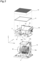
- Fig. 3 is an exploded perspective view illustrating a configuration of a main part of the air purifier 1. Note that, in Fig. 3 , the lower frame 60 and the fan housing 18 are each illustrated as a cross section taken along the line II-II in Fig. 1 .
- the lower frame 60 includes the bottom portion 61 having an opening 61a to which the blow-out port 18d of the fan housing 18 is connected, and a wall portion 62 extending upward from an outer peripheral edge of the bottom portion 61.
- a peripheral step 63 is formed at a distance from the bottom portion 61.
- the primary filter 31 and the secondary filter 32 are supported by an upper surface of the peripheral step 63 with the secondary filter 32 stacked on top of the primary filter 31.
- Abase 71 having an inclined surface 71a is provided on a surface of the bottom portion 61 of the lower frame 60 facing the primary filter 31.
- the irradiator 70 is attached to the inclined surface 71a of the base 71.
- Fig. 4 is a cross-sectional view taken along the line II-II in Fig. 1 .
- arrows indicate the flow of air through the air passage P1.
- Fig. 5 is a cross-sectional view taken along a line V-V in Fig. 4 , and in Fig. 5 , when the fan F rotates in a clockwise direction (arrow R1), air sucked from both sides in a direction perpendicular to the paper surface blows radially outward of the fan F and is straightened by the scroll 18c of the fan housing 18 to blow upward from the blow-out port 18d.
- Fig. 6 is a cross-sectional view taken along a line VI-VI in Fig. 4 , and a second air passage P2 is formed along the up-down direction on a side surface of the lower frame 60.
- the second air passage P2 has an upper end connected to a downstream side of the secondary filter 32 in the air passage P1, and has a lower end connected to a discharge unit 80a of the streamer unit 80.
- the streamer unit 80 causes the discharge unit 80a to perform streamer discharge to generate low-temperature plasma, which generates highly reactive active species (fast electrons, ions, radicals, ozone, or the like) in the air.
- Purified air from the downstream side of the secondary filter 32 in the air passage P1 is supplied to the streamer unit 80 through the second air passage P2, and is sucked into the fan F together with the active species generated by the discharge unit 80a of the streamer unit 80.
- This active species can sterilize viruses and bacteria in air sucked from the right suction port 21 and the left suction port 22 and decompose allergen substances and odors in the air. Since the purified air is supplied to the discharge unit 80a of the streamer unit 80, it is possible to reduce the adhesion of impurities to a needle of the discharge unit 80a and suppress deterioration in the active species generation performance of the streamer unit 80.
- the active species generated by the streamer unit 80 spread throughout the air passage P1, so that it is possible to disinfect components such as the fan F located upstream of the primary filter 31 in the air passage P1. Further, the active species generated by the streamer unit 80 are supplied to all over the primary filter 31, so that it is possible to disinfect a part of the primary filter 31 where the illuminance of the ultraviolet light emitted from the irradiator 70 is low. Furthermore, the active species generated by the streamer unit 80 spread deep into folds of the secondary filter 32 having a pleated structure, producing a disinfection effect, so that it is possible to increase disinfection performance.
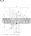
- Fig. 7 illustrates an irradiation region of the irradiator 70, and, as illustrated in Fig. 7 , the irradiator 70 is disposed at a distance in the X-axis direction from a center line L1 passing through a center O1 of the primary filter 31 and orthogonal to the primary filter 31.
- An optical axis L2 of the ultraviolet light emitted from the irradiator 70 is inclined relative to a plane orthogonal to a thickness direction of the primary filter 31.
- an angle ⁇ formed by the optical axis L2 of the ultraviolet light emitted from the irradiator 70 and the plane orthogonal to the thickness direction of the primary filter 31 is about 60 degrees.
- the optical axis L2 of the ultraviolet light emitted from the irradiator 70 passes through a center portion of the primary filter 31.
- the center portion of the primary filter 31 is a region extending from the center O1 of the primary filter 31 toward an outer edge of the primary filter 31 by 1/2 or less of a distance from the center O1 to the outer edge.
- the center O1 of the primary filter 31 falls within an irradiation region S1 having a relative luminous intensity in directivity of the irradiator 70 greater than or equal to 50%.
- a region of the primary filter 31 outside the irradiation region S1 is also irradiated with ultraviolet light having a relative luminous intensity of less than 50% within a range of the directivity of the irradiator 70.
- a directivity angle for the irradiation region S1 is, for example, ⁇ 65 degrees, which makes a region that can be irradiated wider.
- an irradiation area of the primary filter 31 in the irradiation region S1 of the irradiator 70 denoted as A
- an irradiation area B of the primary filter 31 in an irradiation region S2 of the irradiator 70 is smaller than the irradiation area A.
- the irradiation area A of the primary filter 31 is about 1.6 times the irradiation area B.
- the optical axis L2 of the ultraviolet light emitted from the irradiator 70 is inclined relative to the plane orthogonal to the thickness direction of the primary filter 31, so that it is possible to increase the irradiation region of the primary filter 31 irradiated with the ultraviolet light without increasing a distance in the Z-axis direction between the irradiator 70 and the primary filter 31, which allows efficient disinfection of the primary filter 31.
- the air purifier 1 having the above-described configuration causes the primary filter 31 to trap dust contained in the air sucked from the right suction port 21 and the left suction port 22 by the fan F and further causes the secondary filter 32 finer than the primary filter 31 to trap viruses together with the remaining small amount of dust.
- the primary filter 31 first traps dust, so that deterioration in sterilization performance of the secondary filter 32 caused by dust is suppressed, and viruses trapped by the secondary filter 32 are efficiently inactivated by the secondary filter 32 having antiviral properties. It is therefore possible to quickly disinfect an indoor space.
- Irradiating the upstream surface of the primary filter 31 with the ultraviolet light emitted from the irradiator 70 also allows the ultraviolet light to inactivate viruses attached to dust trapped by the primary filter 31, so that it is possible to increase the sterilization performance.
- the ultraviolet light emitted from the irradiator 70 can reach the downstream surface of the primary filter 31, so that it is possible to irradiate the entirety of the thickness of the primary filter 31 with the ultraviolet light and thus increase the sterilization performance of the primary filter 31.
- the secondary filter 32 is a filter having a pleated structure, so that it is possible to make an area for trapping viruses larger and thus increase the sterilization performance of the secondary filter 32 having antiviral properties. Even when the secondary filter 32 having a pleated structure is irradiated with ultraviolet light, the ultraviolet light is applied only to a part of the windward surface of the secondary filter 32, and viruses attached to the folds of the pleats cannot be inactivated; however, it is possible to inactivate, using the secondary filter 32 impregnated with a chemical agent exhibiting antiviral properties, the viruses attached to the folds of the pleats.
- Relatively large dust contained in the air sucked from the right suction port 21 and the left suction port 22 by the fan F is trapped by the pre-filters 24 and 25 each disposed upstream of the primary filter 31 in the air passage P1, so that it is possible to prevent the primary filter 31 from being clogged.
- the bottom portion 61 (partitioning member) of the lower frame 60 is provided upstream of the primary filter 31 and downstream of the fan F, and the irradiator 70 is attached to the downstream surface of the bottom portion 61 of the lower frame 60, so that the air from the fan F is prevented from directly striking the irradiator 70, and it is therefore possible to reduce the adhesion of dust to the irradiator 70.
- the base 71 is provided on the surface of the bottom portion 61 of the lower frame 60 facing the primary filter 31, and the irradiator 70 is attached to the inclined surface 71a of the base 71, so that it is possible to easily attach the irradiator 70 with the optical axis L2 of the irradiator 70 inclined relative to the plane orthogonal to the thickness direction of the primary filter 31.
- the air from the fan F blows out from the opening provided in the bottom portion 61 of the lower frame 60 toward the primary filter 31, so that the air from the fan F is prevented from directly striking the irradiator 70, and it is therefore possible to reduce the adhesion of dust to the irradiator 70.
- the ultraviolet light emitted from the irradiator 70 passes through the center portion of the primary filter 31, so that it is possible to irradiate the entirety of the primary filter 31 or almost the entirety of the primary filter 31 with the ultraviolet light without uneven irradiation on the primary filter 31.
- the irradiator 70 is disposed out of alignment with the center line L1 passing through the center O1 of the primary filter 31 and orthogonal to the primary filter 31, so that it is possible to prevent the irradiator 70 from hindering the flow of air through the primary filter 31.
- the center O1 of the primary filter 31 falls within the irradiation region having a relative luminous intensity in the directivity of the irradiator 70 greater than or equal to 50%, so that it is possible to irradiate the entirety of the primary filter 31 or almost the entirety of the primary filter 31 with the ultraviolet light without uneven irradiation on the primary filter 31.
- One irradiator 70 can irradiate the entirety of the primary filter 31 or almost the entirety of the primary filter 31 with the ultraviolet light without an increase in the distance between the irradiator 70 and the primary filter 31, so that it is possible to reduce the cost and the power consumption as compared with a case where a plurality of irradiators 70 are used.
- the air purifier 1 has been described as an example of the air conditioner, but the present disclosure may be applied to an air conditioner having a cooling function or a heating function.
- the air purifier 1 in which the fan F is disposed upstream of the primary filter 31 and the secondary filter 32 has been described, but the fan may be disposed downstream of the primary filter and the secondary filter.
Landscapes
- Engineering & Computer Science (AREA)
- Chemical & Material Sciences (AREA)
- Combustion & Propulsion (AREA)
- Mechanical Engineering (AREA)
- General Engineering & Computer Science (AREA)
- Health & Medical Sciences (AREA)
- Chemical Kinetics & Catalysis (AREA)
- Life Sciences & Earth Sciences (AREA)
- Animal Behavior & Ethology (AREA)
- General Health & Medical Sciences (AREA)
- Public Health (AREA)
- Veterinary Medicine (AREA)
- Epidemiology (AREA)
- Disinfection, Sterilisation Or Deodorisation Of Air (AREA)
- Air Filters, Heat-Exchange Apparatuses, And Housings Of Air-Conditioning Units (AREA)
- Filtering Of Dispersed Particles In Gases (AREA)
Abstract
Description
- The present disclosure relates to an air conditioner.
- There has been disclosed an air conditioner including an ultraviolet lamp (see, for example,
JP 2004-61078 A - In the air conditioner described above, the ultraviolet lamp irradiates a windward surface of the dust collecting filter with the ultraviolet light to kill viruses and the like attached to the windward surface of the dust collecting filter.
- Patent Literature 1:
JP 2004-61078 A - The dust collecting filter in the air conditioner described above, however, has a structure folded into a pleated shape, so that the ultraviolet light is applied only to a part of the windward surface of the dust collecting filter, or large dust accumulates on the dust collecting filter, which makes sterilization of the dust collecting filter insufficient.
- The present disclosure proposes an air conditioner capable of sufficiently sterilizing indoor spaces.
- An air conditioner of the present disclosure includes:
- a casing provided with an air passage having a suction port and a blow-out port;
- a fan that is disposed in the air passage and blows out, from the blow-out port, air sucked from the suction port;
- a primary filter disposed in the air passage; and
- a secondary filter disposed downstream of the primary filter in the air passage, in which
- the secondary filter is finer than the primary filter and has antiviral properties or antibacterial properties.
- According to the present disclosure, the primary filter traps dust contained in the air sucked from the suction port by the fan, and the secondary filter finer than the primary filter further traps viruses together with the remaining small amount of dust. The primary filter first traps dust, so that deterioration in sterilization performance of the secondary filter caused by dust is suppressed. In such a situation, viruses trapped by the secondary filter are killed by the secondary filter having antiviral properties or antibacterial properties. It is therefore possible to sufficiently sterilize indoor spaces. Herein, sterilization and disinfection include inactivation of viruses.
- The air conditioner according to one aspect of the present disclosure further includes an irradiator that irradiates an upstream surface of the primary filter with ultraviolet light.
- According to the present disclosure, irradiating the upstream surface of the primary filter with the ultraviolet light emitted from the irradiator also allows the ultraviolet light to kill viruses and bacteria attached to dust trapped by the primary filter, so that it is possible to increase the sterilization performance.
- In the air conditioner according to one aspect of the present disclosure, a thickness of the primary filter is set so as to allow the ultraviolet light emitted from the irradiator to reach a downstream surface of the primary filter.
- According to the present disclosure, the ultraviolet light emitted from the irradiator can reach the downstream surface of the primary filter, so that it is possible to irradiate the entirety of the thickness of the primary filter with the ultraviolet light and thus increase the sterilization performance of the primary filter.
- In the air conditioner according to one aspect of the present disclosure, the secondary filter is a filter having a pleated structure.
- According to the present disclosure, the secondary filter is a filter having a pleated structure, so that it is possible to make an area for trapping viruses larger and thus increase the sterilization performance of the secondary filter having antiviral properties or antibacterial properties.
- The air conditioner according to one aspect of the present disclosure further includes a pre-filter disposed upstream of the primary filter in the air passage.
- According to the present disclosure, relatively large dust contained in the air sucked from the suction port by the fan is trapped by the pre-filter disposed upstream of the primary filter in the air passage, so that it is possible to prevent the primary filter from being clogged.
- The air conditioner according to one aspect of the present disclosure further includes a generator that generates active species, in which
the active species are supplied from the generator to the primary filter. - According to the present disclosure, it is possible to sterilize the primary filter with the active species (fast electrons, ions, radicals, ozone, or the like) supplied from the generator.
- The air conditioner according to one aspect of the present disclosure further includes a generator that is disposed upstream of the primary filter in the air passage and generates active species.
- According to the present disclosure, it is possible to kill viruses and bacteria in the air sucked from the suction port and decompose allergen substances and odors by generating the active species (fast electrons, ions, radicals, ozone, or the like) from the generator disposed upstream of the primary filter in the air passage.
-
-
Fig. 1 is an external perspective view of an air purifier according to an embodiment of the present disclosure. -
Fig. 2 is a perspective view of a cross section taken along a line II-II inFig. 1 . -
Fig. 3 is an exploded perspective view illustrating a configuration of a main part of the air purifier. -
Fig. 4 is a cross-sectional view taken along the line II-II inFig. 1 . -
Fig. 5 is a cross-sectional view taken along a line V-V inFig. 4 . -
Fig. 6 is a cross-sectional view taken along a line VI-VI inFig. 4 . -
Fig. 7 is a diagram schematically illustrating an irradiation region of an irradiator. - Hereinafter, an embodiment will be described. It should be noted that in the drawings, the same reference numerals represent the same or corresponding parts. In addition, the dimensions on the drawings, such as lengths, widths, thicknesses, and depths, are appropriately changed from actual scales for clarity and simplification of the drawings, and do not represent actual relative dimensions. In the drawings, a left-right direction is defined as an X-axis direction, a front-rear direction is defined as a Y-axis direction, and an up-down direction is defined as a Z-axis direction.
-
Fig. 1 is an external perspective view of anair purifier 1 according to an embodiment of the present disclosure as viewed from front and obliquely above, andFig. 2 is a perspective view of a cross section taken along a line II-II inFig. 1 . Theair purifier 1 of this embodiment is an example of an air conditioner. - As illustrated in
Figs. 1 and2 , theair purifier 1 includes acasing 10 with a rectangular parallelepiped shape, a fan F, aprimary filter 31, and asecondary filter 32. Thecasing 10 is provided with an air passage P1 having aright suction port 21, aleft suction port 22, and a blow-outport 23. The fan F is disposed in the air passage P1 and blows out, through the blow-outport 23, air sucked from theright suction port 21 and theleft suction port 22. Theprimary filter 31 is disposed in the air passage P1. Thesecondary filter 32 is disposed downstream of theprimary filter 31 in the air passage P1. - The
air purifier 1 further includes anirradiator 70 that irradiates an upstream surface of theprimary filter 31 with ultraviolet light, and astreamer unit 80 disposed upstream of theprimary filter 31 in the air passage P1. Thestreamer unit 80 is an example of a generator that generates active species. - The
casing 10 includes afront panel 11, left andright side panels 12, atop panel 13, a rear panel 14 (illustrated inFig. 5 ), aright suction grille 15 detachably attached below theright side panel 12, aleft suction grille 16 detachably attached below theleft side panel 12, and a blow-outgrille 17 detachably attached to thetop panel 13. - The
right suction port 21 is covered with theright suction grille 15 having a grid shape so as to allow air to flow through. Theleft suction port 22 is covered with theleft suction grille 16 having a grid shape so as to allow air to flow through. The blow-outport 23 is covered with the blow-outgrille 17 having a grid shape so as to allow air to flow through. - A
resin case 40 to which a deodorizing filter (not illustrated) is attachable is detachably attached to thecasing 10. Further, anupper frame 50 is fitted into thecasing 10 above theresin case 40. - Note that the
casing 10 is configured to prevent the ultraviolet light from leaking out from theirradiator 70 provided in the casing 10 (in accordance with IEC standard 60335-2-40 (illuminance of 0.2 µW/cm2 or less at a distance of 0.3 m from an outer contour)). - The fan F is a sirocco fan that sucks air from both sides in an axial direction and blows the air radially outward. The fan F is installed in a
fan housing 18 having left andright suction ports Fig. 3 andFig. 4 ) and ascroll 18c. Thefan housing 18 is provided with a blow-outport 18d through which air sucked from thesuction ports Fig. 4 ). - In the
casing 10, alower frame 60 is disposed above thefan housing 18, thelower frame 60 having a box shape and being opened upward. Thelower frame 60 and theupper frame 50 form a space in which theresin case 40 is installed. - The
irradiator 70 that irradiates the upstream surface theprimary filter 31 with the ultraviolet light is attached to abottom portion 61 of thelower frame 60. Thebottom portion 61 of thelower frame 60 is an example of a partitioning member. - The
primary filter 31 is a filter capable of removing particles having a particle diameter of 10 µm to 50 µm. A thickness of theprimary filter 31 is set so as to allow the ultraviolet light from theirradiator 70 to reach a downstream surface of the primary filter 31 (for example, a thickness of about 5 mm to 10 mm). Here, theirradiator 70 includes a light emitting diode (LED) that emits deep ultraviolet light UV-C in a wavelength region of 100 nm to 280 nm. - Note that, in the present embodiment, the
irradiator 70 that emits the deep ultraviolet light UV-C in the wavelength range of 100 nm to 280 nm is used, but any irradiator that emits ultraviolet light within a wavelength range of 100 nm to 400 nm may be used. Alternatively, an ultraviolet lamp or the like may be used as the irradiator. - The
secondary filter 32 is a filter having a pleated structure, and is a filter that traps particles having a particle diameter of 0.7 µm. For example, the filter may be a high efficiency particulate air (HEPA) filter that traps 99.97% or more of particles having a particle diameter of 0.3 µm or a medium efficiency particulate air filter that traps particles having a particle diameter of 0.4 µm to 0.7 µm. Thesecondary filter 32 is impregnated with a chemical agent exhibiting antiviral properties. For example, a lytic enzyme that destroys the envelopes of viruses to inactivate the viruses is used as the chemical agent. - Note that the secondary filter may be impregnated with a chemical agent exhibiting antibacterial properties to inhibit the growth of bacteria, or both the chemical agent exhibiting antiviral properties and the chemical agent exhibiting antibacterial properties may be used. Examples of the chemical agent exhibiting antiviral properties and antibacterial properties include Ag, an enzyme, ammonia, and the like, and a chemical agent containing a mixture of at least two of Ag, an enzyme, ammonia, and the like may be used.
- Net-
like pre-filters right suction grille 15 and a leeward surface of theleft suction grille 16, respectively. The pre-filters 24 and 25 are each disposed upstream of theprimary filter 31 in the air passage P1. The pre-filters 24 and 25 trap dust larger than particles to be trapped by theprimary filter 31. - The air passage P1 is formed in the
casing 10. Air sucked in the air passage P1 from theright suction port 21 and theleft suction port 22 blows out from the blow-outport 23 via the fan F, theprimary filter 31, and thesecondary filter 32 -
Fig. 3 is an exploded perspective view illustrating a configuration of a main part of theair purifier 1. Note that, inFig. 3 , thelower frame 60 and thefan housing 18 are each illustrated as a cross section taken along the line II-II inFig. 1 . - As illustrated in
Fig. 3 , thelower frame 60 includes thebottom portion 61 having anopening 61a to which the blow-outport 18d of thefan housing 18 is connected, and awall portion 62 extending upward from an outer peripheral edge of thebottom portion 61. In thewall portion 62, aperipheral step 63 is formed at a distance from thebottom portion 61. Theprimary filter 31 and thesecondary filter 32 are supported by an upper surface of theperipheral step 63 with thesecondary filter 32 stacked on top of theprimary filter 31. -
Abase 71 having aninclined surface 71a is provided on a surface of thebottom portion 61 of thelower frame 60 facing theprimary filter 31. Theirradiator 70 is attached to theinclined surface 71a of thebase 71. -
Fig. 4 is a cross-sectional view taken along the line II-II inFig. 1 . InFig. 4 , arrows indicate the flow of air through the air passage P1. - As illustrated in
Fig. 4 , when the fan F is driven by the motor M, air sucked by the fan F from theright suction port 21 and theleft suction port 22 blows upward from the fan F and then blows upward from the blow-outport 23 through theprimary filter 31 and thesecondary filter 32. -
Fig. 5 is a cross-sectional view taken along a line V-V inFig. 4 , and inFig. 5 , when the fan F rotates in a clockwise direction (arrow R1), air sucked from both sides in a direction perpendicular to the paper surface blows radially outward of the fan F and is straightened by thescroll 18c of thefan housing 18 to blow upward from the blow-outport 18d. -
Fig. 6 is a cross-sectional view taken along a line VI-VI inFig. 4 , and a second air passage P2 is formed along the up-down direction on a side surface of thelower frame 60. The second air passage P2 has an upper end connected to a downstream side of thesecondary filter 32 in the air passage P1, and has a lower end connected to adischarge unit 80a of thestreamer unit 80. Thestreamer unit 80 causes thedischarge unit 80a to perform streamer discharge to generate low-temperature plasma, which generates highly reactive active species (fast electrons, ions, radicals, ozone, or the like) in the air. - Purified air from the downstream side of the
secondary filter 32 in the air passage P1 is supplied to thestreamer unit 80 through the second air passage P2, and is sucked into the fan F together with the active species generated by thedischarge unit 80a of thestreamer unit 80. This active species can sterilize viruses and bacteria in air sucked from theright suction port 21 and theleft suction port 22 and decompose allergen substances and odors in the air. Since the purified air is supplied to thedischarge unit 80a of thestreamer unit 80, it is possible to reduce the adhesion of impurities to a needle of thedischarge unit 80a and suppress deterioration in the active species generation performance of thestreamer unit 80. - Note that the active species generated by the
streamer unit 80 spread throughout the air passage P1, so that it is possible to disinfect components such as the fan F located upstream of theprimary filter 31 in the air passage P1. Further, the active species generated by thestreamer unit 80 are supplied to all over theprimary filter 31, so that it is possible to disinfect a part of theprimary filter 31 where the illuminance of the ultraviolet light emitted from theirradiator 70 is low. Furthermore, the active species generated by thestreamer unit 80 spread deep into folds of thesecondary filter 32 having a pleated structure, producing a disinfection effect, so that it is possible to increase disinfection performance. -
Fig. 7 illustrates an irradiation region of theirradiator 70, and, as illustrated inFig. 7 , theirradiator 70 is disposed at a distance in the X-axis direction from a center line L1 passing through a center O1 of theprimary filter 31 and orthogonal to theprimary filter 31. - An optical axis L2 of the ultraviolet light emitted from the
irradiator 70 is inclined relative to a plane orthogonal to a thickness direction of theprimary filter 31. In the present embodiment, an angle θ formed by the optical axis L2 of the ultraviolet light emitted from theirradiator 70 and the plane orthogonal to the thickness direction of theprimary filter 31 is about 60 degrees. - The optical axis L2 of the ultraviolet light emitted from the irradiator 70 passes through a center portion of the
primary filter 31. Here, the center portion of theprimary filter 31 is a region extending from the center O1 of theprimary filter 31 toward an outer edge of theprimary filter 31 by 1/2 or less of a distance from the center O1 to the outer edge. - The center O1 of the
primary filter 31 falls within an irradiation region S1 having a relative luminous intensity in directivity of theirradiator 70 greater than or equal to 50%. Note that a region of theprimary filter 31 outside the irradiation region S1 is also irradiated with ultraviolet light having a relative luminous intensity of less than 50% within a range of the directivity of theirradiator 70. In theirradiator 70, a directivity angle for the irradiation region S1 is, for example, ±65 degrees, which makes a region that can be irradiated wider. - Here, with an irradiation area of the
primary filter 31 in the irradiation region S1 of the irradiator 70 denoted as A, when theirradiator 70 is disposed such that the optical axis L2 of theirradiator 70 coincides with the center line L1 orthogonal to theprimary filter 31, an irradiation area B of theprimary filter 31 in an irradiation region S2 of theirradiator 70 is smaller than the irradiation area A. In the present embodiment, the irradiation area A of theprimary filter 31 is about 1.6 times the irradiation area B. - As described above, the optical axis L2 of the ultraviolet light emitted from the
irradiator 70 is inclined relative to the plane orthogonal to the thickness direction of theprimary filter 31, so that it is possible to increase the irradiation region of theprimary filter 31 irradiated with the ultraviolet light without increasing a distance in the Z-axis direction between the irradiator 70 and theprimary filter 31, which allows efficient disinfection of theprimary filter 31. - The
air purifier 1 having the above-described configuration causes theprimary filter 31 to trap dust contained in the air sucked from theright suction port 21 and theleft suction port 22 by the fan F and further causes thesecondary filter 32 finer than theprimary filter 31 to trap viruses together with the remaining small amount of dust. Theprimary filter 31 first traps dust, so that deterioration in sterilization performance of thesecondary filter 32 caused by dust is suppressed, and viruses trapped by thesecondary filter 32 are efficiently inactivated by thesecondary filter 32 having antiviral properties. It is therefore possible to quickly disinfect an indoor space. - With a conventional air purifier using a normal HEPA filter as the secondary filter and including neither the primary filter nor the irradiator, it has taken about 2.5 hours to disinfect 99% of an eight-tatami-mat room (about 26.4 m2) at an air volume of 5.0 m/min, whereas with the
air purifier 1 of the present embodiment, 99% of the room has been successfully disinfected in about 30 minutes at an air volume of 5.0 m/min under the same conditions. - Irradiating the upstream surface of the
primary filter 31 with the ultraviolet light emitted from theirradiator 70 also allows the ultraviolet light to inactivate viruses attached to dust trapped by theprimary filter 31, so that it is possible to increase the sterilization performance. - The ultraviolet light emitted from the
irradiator 70 can reach the downstream surface of theprimary filter 31, so that it is possible to irradiate the entirety of the thickness of theprimary filter 31 with the ultraviolet light and thus increase the sterilization performance of theprimary filter 31. - The
secondary filter 32 is a filter having a pleated structure, so that it is possible to make an area for trapping viruses larger and thus increase the sterilization performance of thesecondary filter 32 having antiviral properties. Even when thesecondary filter 32 having a pleated structure is irradiated with ultraviolet light, the ultraviolet light is applied only to a part of the windward surface of thesecondary filter 32, and viruses attached to the folds of the pleats cannot be inactivated; however, it is possible to inactivate, using thesecondary filter 32 impregnated with a chemical agent exhibiting antiviral properties, the viruses attached to the folds of the pleats. - Relatively large dust contained in the air sucked from the
right suction port 21 and theleft suction port 22 by the fan F is trapped by the pre-filters 24 and 25 each disposed upstream of theprimary filter 31 in the air passage P1, so that it is possible to prevent theprimary filter 31 from being clogged. - The bottom portion 61 (partitioning member) of the
lower frame 60 is provided upstream of theprimary filter 31 and downstream of the fan F, and theirradiator 70 is attached to the downstream surface of thebottom portion 61 of thelower frame 60, so that the air from the fan F is prevented from directly striking theirradiator 70, and it is therefore possible to reduce the adhesion of dust to theirradiator 70. - The
base 71 is provided on the surface of thebottom portion 61 of thelower frame 60 facing theprimary filter 31, and theirradiator 70 is attached to theinclined surface 71a of thebase 71, so that it is possible to easily attach theirradiator 70 with the optical axis L2 of theirradiator 70 inclined relative to the plane orthogonal to the thickness direction of theprimary filter 31. - The air from the fan F blows out from the opening provided in the
bottom portion 61 of thelower frame 60 toward theprimary filter 31, so that the air from the fan F is prevented from directly striking theirradiator 70, and it is therefore possible to reduce the adhesion of dust to theirradiator 70. - The ultraviolet light emitted from the irradiator 70 passes through the center portion of the
primary filter 31, so that it is possible to irradiate the entirety of theprimary filter 31 or almost the entirety of theprimary filter 31 with the ultraviolet light without uneven irradiation on theprimary filter 31. - The
irradiator 70 is disposed out of alignment with the center line L1 passing through the center O1 of theprimary filter 31 and orthogonal to theprimary filter 31, so that it is possible to prevent the irradiator 70 from hindering the flow of air through theprimary filter 31. - The center O1 of the
primary filter 31 falls within the irradiation region having a relative luminous intensity in the directivity of theirradiator 70 greater than or equal to 50%, so that it is possible to irradiate the entirety of theprimary filter 31 or almost the entirety of theprimary filter 31 with the ultraviolet light without uneven irradiation on theprimary filter 31. - One
irradiator 70 can irradiate the entirety of theprimary filter 31 or almost the entirety of theprimary filter 31 with the ultraviolet light without an increase in the distance between the irradiator 70 and theprimary filter 31, so that it is possible to reduce the cost and the power consumption as compared with a case where a plurality ofirradiators 70 are used. - In the above-described embodiment, the
air purifier 1 has been described as an example of the air conditioner, but the present disclosure may be applied to an air conditioner having a cooling function or a heating function. - In the above-described embodiment, the
air purifier 1 in which the fan F is disposed upstream of theprimary filter 31 and thesecondary filter 32 has been described, but the fan may be disposed downstream of the primary filter and the secondary filter. - Although a specific embodiment of the present disclosure has been described, the present disclosure is not limited to the above-described embodiment, and various modifications can be made within the scope of the present disclosure.
-
- 1
- air purifier
- 10
- casing
- 11
- front panel
- 12
- side panel
- 13
- top panel
- 14
- rear panel
- 15
- right suction grille
- 16
- left suction grille
- 17
- blow-out grille
- 18
- fan housing
- 18a, 18b
- suction port
- 18c
- scroll
- 18d
- blow-out port
- 19
- shaft
- 21
- right suction port
- 22
- left suction port
- 23
- blow-out port
- 24, 25
- pre-filter
- 31
- primary filter
- 32
- secondary filter
- 40
- resin case
- 50
- upper frame
- 60
- lower frame
- 61
- bottom portion (partitioning member)
- 61a
- opening
- 62
- wall portion
- 63
- peripheral step
- 70
- irradiation unit
- 71
- base
- 71a
- inclined surface
- 80
- streamer unit
- 80a
- discharge unit
- F
- fan
- M
- motor
- P1
- air passage
- P2
- second air passage
Claims (6)
- An air conditioner comprising:a casing (10) provided with an air passage (P1) having a suction port (21, 22) and a blow-out port (23);a fan (F) that is disposed in the air passage (P1) and blows out, from the blow-out port (23), air sucked from the suction port (21, 22);a primary filter (31) disposed in the air passage (P1); anda secondary filter (32) disposed downstream of the primary filter (31) in the air passage (P1), whereinthe secondary filter (32) is finer than the primary filter (31) and has antiviral properties or antibacterial properties.
- The air conditioner according to claim 1, further comprising an irradiator (70) that irradiates an upstream surface of the primary filter (31) with ultraviolet light.
- The air conditioner according to claim 2, wherein
a thickness of the primary filter (31) is set so as to allow the ultraviolet light emitted from the irradiator (70) to reach a downstream surface of the primary filter (31). - The air conditioner according to any one of claims 1 to 3, wherein
the secondary filter (32) is a filter having a pleated structure. - The air conditioner according to any one of claims 1 to 4, further comprising a pre-filter (24, 25) disposed upstream of the primary filter (31) in the air passage (P1).
- The air conditioner according to any one of claims 1 to 5, further comprising a generator (80) that generates active species, wherein
the active species are supplied from the generator (80) to the primary filter (31).
Applications Claiming Priority (2)
| Application Number | Priority Date | Filing Date | Title |
|---|---|---|---|
| JP2021024284A JP7307356B2 (en) | 2021-02-18 | 2021-02-18 | air conditioner |
| PCT/JP2022/001588 WO2022176479A1 (en) | 2021-02-18 | 2022-01-18 | Air conditioner |
Publications (2)
| Publication Number | Publication Date |
|---|---|
| EP4279828A1 true EP4279828A1 (en) | 2023-11-22 |
| EP4279828A4 EP4279828A4 (en) | 2024-07-10 |
Family
ID=82930828
Family Applications (1)
| Application Number | Title | Priority Date | Filing Date |
|---|---|---|---|
| EP22755804.6A Withdrawn EP4279828A4 (en) | 2021-02-18 | 2022-01-18 | AIR CONDITIONER |
Country Status (5)
| Country | Link |
|---|---|
| US (1) | US20230392804A1 (en) |
| EP (1) | EP4279828A4 (en) |
| JP (1) | JP7307356B2 (en) |
| CN (1) | CN116829878A (en) |
| WO (1) | WO2022176479A1 (en) |
Families Citing this family (1)
| Publication number | Priority date | Publication date | Assignee | Title |
|---|---|---|---|---|
| JP7815735B2 (en) * | 2021-12-15 | 2026-02-18 | 新東工業株式会社 | Dust collector |
Family Cites Families (18)
| Publication number | Priority date | Publication date | Assignee | Title |
|---|---|---|---|---|
| CA2295302C (en) * | 1996-07-25 | 2005-05-31 | Nikki-Universal Co., Ltd. | Air purifying filter |
| US5997619A (en) * | 1997-09-04 | 1999-12-07 | Nq Environmental, Inc. | Air purification system |
| JP3924589B2 (en) * | 1998-11-25 | 2007-06-06 | 川崎設備工業株式会社 | Air cleaner |
| US6589489B2 (en) * | 2001-03-30 | 2003-07-08 | L2B Environmental Systems Inc. | Air purifier |
| JP2004061078A (en) | 2002-07-31 | 2004-02-26 | Sanyo Electric Co Ltd | Air cleaner |
| US6869458B2 (en) | 2003-05-05 | 2005-03-22 | Sanki Engineering Co., Ltd. | Bioclean room unit |
| JP2005342509A (en) | 2004-06-21 | 2005-12-15 | Hirobumi Miyagawa | Air sterilizer/deodorizer |
| JP2006046730A (en) * | 2004-08-02 | 2006-02-16 | Sharp Corp | Dust collection filter and air cleaner using the same |
| CN2778367Y (en) * | 2005-03-25 | 2006-05-10 | 刘波 | Antibacterial deodorization air filtering screen |
| JP4788731B2 (en) | 2008-04-09 | 2011-10-05 | ダイキン工業株式会社 | Air cleaner |
| JP5195595B2 (en) | 2009-04-02 | 2013-05-08 | パナソニック株式会社 | Photocatalyst deodorizer |
| JP5770462B2 (en) * | 2010-07-22 | 2015-08-26 | 株式会社クワン | Method for producing seeded pomegranate juice, seeded pomegranate juice comprising the production method, and pomegranate juice-containing jelly using the seeded pomegranate juice |
| JP6482885B2 (en) | 2015-01-28 | 2019-03-13 | トヨタホーム株式会社 | Building air conditioning ventilation system |
| JP6323404B2 (en) * | 2015-07-10 | 2018-05-16 | ダイキン工業株式会社 | Air cleaner |
| US11260143B2 (en) * | 2016-11-22 | 2022-03-01 | Seoul Viosys Co., Ltd. | Air purifier |
| CN106705265A (en) * | 2017-02-24 | 2017-05-24 | 北京金淏源净化技术有限公司 | Integrated photo-catalytic sterilization air refreshing device |
| JP6317495B1 (en) * | 2017-03-08 | 2018-04-25 | 日機装株式会社 | Air purifier |
| JP7011401B2 (en) | 2017-04-24 | 2022-01-26 | 日本無機株式会社 | Air purifier and air purifying method |
-
2021
- 2021-02-18 JP JP2021024284A patent/JP7307356B2/en active Active
-
2022
- 2022-01-18 WO PCT/JP2022/001588 patent/WO2022176479A1/en not_active Ceased
- 2022-01-18 EP EP22755804.6A patent/EP4279828A4/en not_active Withdrawn
- 2022-01-18 CN CN202280014158.7A patent/CN116829878A/en active Pending
-
2023
- 2023-08-16 US US18/234,585 patent/US20230392804A1/en active Pending
Also Published As
| Publication number | Publication date |
|---|---|
| JP7307356B2 (en) | 2023-07-12 |
| WO2022176479A1 (en) | 2022-08-25 |
| EP4279828A4 (en) | 2024-07-10 |
| CN116829878A (en) | 2023-09-29 |
| US20230392804A1 (en) | 2023-12-07 |
| JP2022126292A (en) | 2022-08-30 |
Similar Documents
| Publication | Publication Date | Title |
|---|---|---|
| CN201612874U (en) | A kind of indoor air purifier | |
| CN1281898C (en) | Air conditioner | |
| KR20200031423A (en) | Sterilization apparatus and home appliance including the same | |
| US20230392804A1 (en) | Air conditioner | |
| JP2005076906A (en) | Air conditioner | |
| KR20080073472A (en) | Ceiling Flush Air Sterilization Purifier | |
| JP3051083B2 (en) | Air cleaner | |
| EP4273462A1 (en) | Air conditioner | |
| JP2003185180A (en) | Air conditioner | |
| JP2005090831A (en) | Air cleaner | |
| JP4886974B2 (en) | AIR CLEANING UNIT AND AIR CONDITIONER HAVING THE SAME | |
| JP2023066160A (en) | air conditioner | |
| KR20090113695A (en) | air cleaner | |
| CN218672533U (en) | Primary air filtering mechanism, air disinfection host and disinfection lamp | |
| KR20220118639A (en) | Vehicle air sterilizer | |
| CN218599943U (en) | Sterilizing machine | |
| KR100654734B1 (en) | Internal arrangement of air purifier with ultraviolet lamp | |
| CN218599951U (en) | Sterilizing machine | |
| JP2005076908A (en) | Mounting structure and mounting tool for air conditioner and duct body | |
| JP4114527B2 (en) | air purifier | |
| JP2000051332A (en) | Air cleaner | |
| CN211316399U (en) | Underground garage fan with air purification function | |
| CN214465014U (en) | Built-in deep ultraviolet sterilization cooling fan | |
| JP4961659B2 (en) | UV sterilizer | |
| KR20220147226A (en) | Apparatus for sterilizing of air conditioner for vehicle |
Legal Events
| Date | Code | Title | Description |
|---|---|---|---|
| STAA | Information on the status of an ep patent application or granted ep patent |
Free format text: STATUS: THE INTERNATIONAL PUBLICATION HAS BEEN MADE |
|
| PUAI | Public reference made under article 153(3) epc to a published international application that has entered the european phase |
Free format text: ORIGINAL CODE: 0009012 |
|
| STAA | Information on the status of an ep patent application or granted ep patent |
Free format text: STATUS: REQUEST FOR EXAMINATION WAS MADE |
|
| 17P | Request for examination filed |
Effective date: 20230816 |
|
| AK | Designated contracting states |
Kind code of ref document: A1 Designated state(s): AL AT BE BG CH CY CZ DE DK EE ES FI FR GB GR HR HU IE IS IT LI LT LU LV MC MK MT NL NO PL PT RO RS SE SI SK SM TR |
|
| DAV | Request for validation of the european patent (deleted) | ||
| DAX | Request for extension of the european patent (deleted) | ||
| A4 | Supplementary search report drawn up and despatched |
Effective date: 20240612 |
|
| RIC1 | Information provided on ipc code assigned before grant |
Ipc: F24F 8/80 20210101ALI20240606BHEP Ipc: F24F 8/108 20210101ALI20240606BHEP Ipc: B01D 46/52 20060101ALI20240606BHEP Ipc: A61L 9/16 20060101ALI20240606BHEP Ipc: F24F 8/22 20210101AFI20240606BHEP |
|
| P01 | Opt-out of the competence of the unified patent court (upc) registered |
Free format text: CASE NUMBER: APP_38297/2024 Effective date: 20240627 |
|
| STAA | Information on the status of an ep patent application or granted ep patent |
Free format text: STATUS: EXAMINATION IS IN PROGRESS |
|
| 17Q | First examination report despatched |
Effective date: 20241216 |
|
| GRAP | Despatch of communication of intention to grant a patent |
Free format text: ORIGINAL CODE: EPIDOSNIGR1 |
|
| STAA | Information on the status of an ep patent application or granted ep patent |
Free format text: STATUS: GRANT OF PATENT IS INTENDED |
|
| INTG | Intention to grant announced |
Effective date: 20250513 |
|
| STAA | Information on the status of an ep patent application or granted ep patent |
Free format text: STATUS: THE APPLICATION IS DEEMED TO BE WITHDRAWN |
|
| 18D | Application deemed to be withdrawn |
Effective date: 20250916 |