EP4279821A1 - Filter for an aircraft oven - Google Patents
Filter for an aircraft oven Download PDFInfo
- Publication number
- EP4279821A1 EP4279821A1 EP22174108.5A EP22174108A EP4279821A1 EP 4279821 A1 EP4279821 A1 EP 4279821A1 EP 22174108 A EP22174108 A EP 22174108A EP 4279821 A1 EP4279821 A1 EP 4279821A1
- Authority
- EP
- European Patent Office
- Prior art keywords
- filter
- nozzle
- aircraft
- wall
- aircraft oven
- Prior art date
- Legal status (The legal status is an assumption and is not a legal conclusion. Google has not performed a legal analysis and makes no representation as to the accuracy of the status listed.)
- Pending
Links
Images


Classifications
-
- B—PERFORMING OPERATIONS; TRANSPORTING
- B01—PHYSICAL OR CHEMICAL PROCESSES OR APPARATUS IN GENERAL
- B01D—SEPARATION
- B01D46/00—Filters or filtering processes specially modified for separating dispersed particles from gases or vapours
- B01D46/24—Particle separators, e.g. dust precipitators, using rigid hollow filter bodies
-
- F—MECHANICAL ENGINEERING; LIGHTING; HEATING; WEAPONS; BLASTING
- F24—HEATING; RANGES; VENTILATING
- F24C—DOMESTIC STOVES OR RANGES ; DETAILS OF DOMESTIC STOVES OR RANGES, OF GENERAL APPLICATION
- F24C15/00—Details
- F24C15/20—Removing cooking fumes
- F24C15/2007—Removing cooking fumes from oven cavities
-
- A—HUMAN NECESSITIES
- A47—FURNITURE; DOMESTIC ARTICLES OR APPLIANCES; COFFEE MILLS; SPICE MILLS; SUCTION CLEANERS IN GENERAL
- A47J—KITCHEN EQUIPMENT; COFFEE MILLS; SPICE MILLS; APPARATUS FOR MAKING BEVERAGES
- A47J36/00—Parts, details or accessories of cooking-vessels
-
- B—PERFORMING OPERATIONS; TRANSPORTING
- B01—PHYSICAL OR CHEMICAL PROCESSES OR APPARATUS IN GENERAL
- B01D—SEPARATION
- B01D39/00—Filtering material for liquid or gaseous fluids
- B01D39/14—Other self-supporting filtering material ; Other filtering material
- B01D39/20—Other self-supporting filtering material ; Other filtering material of inorganic material, e.g. asbestos paper, metallic filtering material of non-woven wires
- B01D39/2027—Metallic material
-
- B—PERFORMING OPERATIONS; TRANSPORTING
- B01—PHYSICAL OR CHEMICAL PROCESSES OR APPARATUS IN GENERAL
- B01D—SEPARATION
- B01D39/00—Filtering material for liquid or gaseous fluids
- B01D39/14—Other self-supporting filtering material ; Other filtering material
- B01D39/20—Other self-supporting filtering material ; Other filtering material of inorganic material, e.g. asbestos paper, metallic filtering material of non-woven wires
- B01D39/2027—Metallic material
- B01D39/2031—Metallic material the material being particulate
- B01D39/2034—Metallic material the material being particulate sintered or bonded by inorganic agents
-
- B—PERFORMING OPERATIONS; TRANSPORTING
- B01—PHYSICAL OR CHEMICAL PROCESSES OR APPARATUS IN GENERAL
- B01D—SEPARATION
- B01D39/00—Filtering material for liquid or gaseous fluids
- B01D39/14—Other self-supporting filtering material ; Other filtering material
- B01D39/20—Other self-supporting filtering material ; Other filtering material of inorganic material, e.g. asbestos paper, metallic filtering material of non-woven wires
- B01D39/2027—Metallic material
- B01D39/2051—Metallic foam
-
- B—PERFORMING OPERATIONS; TRANSPORTING
- B64—AIRCRAFT; AVIATION; COSMONAUTICS
- B64D—EQUIPMENT FOR FITTING IN OR TO AIRCRAFT; FLIGHT SUITS; PARACHUTES; ARRANGEMENT OR MOUNTING OF POWER PLANTS OR PROPULSION TRANSMISSIONS IN AIRCRAFT
- B64D11/00—Passenger or crew accommodation; Flight-deck installations not otherwise provided for
- B64D11/04—Galleys
-
- F—MECHANICAL ENGINEERING; LIGHTING; HEATING; WEAPONS; BLASTING
- F24—HEATING; RANGES; VENTILATING
- F24C—DOMESTIC STOVES OR RANGES ; DETAILS OF DOMESTIC STOVES OR RANGES, OF GENERAL APPLICATION
- F24C15/00—Details
- F24C15/20—Removing cooking fumes
- F24C15/2035—Arrangement or mounting of filters
Definitions
- This disclosure relates to a filter for an aircraft oven.
- this disclosure relates to a single-piece filter for an aircraft oven.
- Aircraft ovens include an inner cavity and an outer cavity.
- filters are used to ensure that any particles passing between the inner cavity and the outer cavity are captured so as to avoid fault in operation of the aircraft oven.
- the filters require assembly before fitting into the aircraft oven. These filters are also prone to corrosion during their intended use, which can lead to high volumes of maintenance. Therefore, there exists a need for an improved filter for an aircraft oven.
- a filter for an aircraft oven comprises a single-piece of sintered metal or porous aluminium.
- the filter may be cylindrical.
- the filter may include a first end, a second end, an outer wall extending between the first end and the second end, and wherein the filter may further comprise an opening in the second end, an inner first end located between the first end and the second end and an inner wall extending between the inner first end and the opening.
- An area defined by the inner first end, the opening and the inner wall may be hollow.
- an aircraft oven comprising an inner portion and an outer portion.
- the inner portion and the outer portion (22) are separated by a wall.
- the aircraft oven further comprises a nozzle configured to extend from the inner portion to the outer portion through the wall, and a filter as described above provided in the inner portion and provided adjacent the nozzle.
- the filter may be provided over the nozzle.
- the wall may include a recessed area and the filter is configured to be provided in the recessed area.
- the nozzle may extend from the recessed area to the outer portion.
- a method of fitting the filter, as described above, in the aircraft oven comprises providing the filter in the inner portion and adjacent the nozzle.
- the filter may be provided over the nozzle.
- the wall may include a recessed area and the filter is configured to be provided in the recessed area.
- the nozzle may extend from the recessed area to the outer portion.
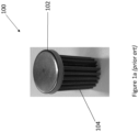
- FIG. 1a shows a filter 100 for an aircraft oven (not shown).
- the filter 100 includes an end cap 102 and a mesh filter 104.
- the mesh filter 104 is manually fixed and attached to the end cap 102. This can lead to error in attaching the mesh filter 104 to the end cap 102 which can result in a fault in the function of the filter 100.
- the end cap 102 and mesh filter 104 may be made from the same or different materials.
- the end cap 102 and mesh filter 104 may be made from various metals. Since the end cap 102 and mesh filter 104 are manually attached before installation, there may be incidences where they are not fitted properly and this may result in the end cap 102 and the mesh filter 104 suffering from a failure (e.g. coming apart) during fitting.
- the end cap 102 and the mesh filter 104 are usually formed from different materials (e.g. different metals), which can lead to corrosion (e.g. dissimilar metal corrosion). Therefore, the filter 100 may need to be maintained frequently or even replaced frequently through the lifetime of the aircraft oven. As can be appreciated, the filter 100 needs to be fitted (or retrofitted) in small spaces in aircraft ovens and, therefore, there are possibilities that the end cap 102 and the mesh filter 104 may come apart during fitment.
- Figure 1b shows the filter of Figure 1a fitted over a nozzle 14 of an aircraft oven.
- the aircraft oven may include an inner portion 10 and an outer portion 12.
- the inner portion 10 and outer portion 12 are separated by a wall 16.
- the nozzle 14 extends through the wall 16.
- air flow moves from the inner portion 10 to the outer portion 12 in the direction of the arrow and through the nozzle 14.
- the mesh filter 104 and end cap 102 are provided over the nozzle 14 in the inner portion 10 of the aircraft oven. In this way, particles can be captured by the mesh filter 104 as the air moves in the direction of the arrow.
- a filter for an aircraft oven may be placed between an inner cavity and an outer cavity to ensure that particles passing between the inner cavity and the outer cavity are captured to ensure a safe functioning of the aircraft oven.
- a single-piece filter for an aircraft oven that is capable of capturing particles so as to avoid assembly before installation and to ensure safe functioning of the aircraft oven.
- FIGs 2a and 2b show an example of a filter 200 for an aircraft oven (not shown).
- the filter 200 has a 'top-hat' configuration and is made from a single material to absorb and/or capture particles during use.
- the filter 200 may include a first end 202 and a second end 204.
- An outer wall 206 extends between the first end 202 and the second end 204.
- the area defined by the inner first end 209, the opening 205 and the inner wall 207 is hollow to allow the filter 200 to be placed over, as an example, a nozzle (or outlet) of the aircraft oven (not shown).
- the filter 200 is formed as a single-piece of material.
- the filter 200 may be formed from sintered metal or porous aluminium such that particles may be captured in the aircraft oven during use.
- the filter 200 is shown as cylindrical in Figures 2a and 2b , it is envisaged that the filter 200 could be any other shape that may be provided to an aircraft oven.
- the filter 200 may be a cuboid or a disc, and the like. Since there is no separate end cap, for example as shown in Figure 1a , the filter 200 includes a greater filter surface area that can be used. Therefore, the filter 200 could be manufactured to be smaller than filters that include an end cap, but still allow for the same flow rate through the aircraft oven.
- Figure 3 shows another example of a filter 300 for an aircraft oven (again, the aircraft oven is not shown).
- the filter 300 of Figure 3 is shown as a solid-piece filter (i.e., without the hollow interior for receiving a nozzle).
- the filter 300 may be positioned between an inner cavity and an outer cavity of an aircraft oven to ensure that particles are captured by the filter 300.
- the filter 300 is formed from sintered metal or porous aluminium.
- the filter 300 is shown as cylindrical in Figure 3 , it is envisaged that the filter 300 could be any other shape that may be provided to an aircraft oven.
- the filter 300 may be a cuboid or a disc, and the like.
- Figure 4a shows an example of the filter of Figures 2a and 2b fitted over a nozzle 24, much in the same way that the filter of Figure 1a is fitted over the nozzle 14 as shown in Figure 1b .
- the inner wall 207, the first end 202 and the inner first end 209 are configured to surround the nozzle 24.
- the aircraft oven may include an inner portion 20 and an outer portion 22.
- the inner portion 20 and the outer portion 22 are separated by a wall 26.
- the nozzle 24 extends through the wall 26. Air can flow from the inner portion 20 to the outer portion 22 in the direction shown by the arrow through the nozzle 24.
- Surrounding the nozzle 24 with the inner wall 207, the first end 202 and the inner first end 209 allows for particles to be captured in the material as air flows from the inner portion 20 of the aircraft oven to the outer portion 22 of the aircraft oven.
- Figure 4b shows another example of the filter of Figures 2a and 2b fitted in a recessed area A of a wall 26 of the aircraft oven.
- the recessed area A is provided in the wall 26 and leads to a nozzle 24.
- the filter may be provided in the recessed area A such that the first end 202 is adjacent the nozzle 24.
- the aircraft oven may include an inner portion 20 and an outer portion 22. The inner portion 20 and the outer portion 22 are separated by the wall 26 and the recessed area A.
- the nozzle 24 extends from the recessed area A to the outer portion 22 to expel air from the inner portion 20.
- the filter may also be a solid piece filter as shown in Figure 3 .
Landscapes
- Chemical & Material Sciences (AREA)
- Engineering & Computer Science (AREA)
- Chemical Kinetics & Catalysis (AREA)
- Life Sciences & Earth Sciences (AREA)
- Geology (AREA)
- Aviation & Aerospace Engineering (AREA)
- General Engineering & Computer Science (AREA)
- Combustion & Propulsion (AREA)
- Mechanical Engineering (AREA)
- Food Science & Technology (AREA)
- Inorganic Chemistry (AREA)
- Filtering Of Dispersed Particles In Gases (AREA)
- Filtering Materials (AREA)
Abstract
Description
- This disclosure relates to a filter for an aircraft oven. In particular, this disclosure relates to a single-piece filter for an aircraft oven.
- Aircraft ovens include an inner cavity and an outer cavity. Typically, filters are used to ensure that any particles passing between the inner cavity and the outer cavity are captured so as to avoid fault in operation of the aircraft oven. Usually, the filters require assembly before fitting into the aircraft oven. These filters are also prone to corrosion during their intended use, which can lead to high volumes of maintenance. Therefore, there exists a need for an improved filter for an aircraft oven.
- In one aspect, there is provided a filter for an aircraft oven, the filter comprises a single-piece of sintered metal or porous aluminium.
- The filter may be cylindrical.
- The filter may include a first end, a second end, an outer wall extending between the first end and the second end, and wherein the filter may further comprise an opening in the second end, an inner first end located between the first end and the second end and an inner wall extending between the inner first end and the opening. An area defined by the inner first end, the opening and the inner wall may be hollow.
- In another aspect, there is provided an aircraft oven. The aircraft oven comprises an inner portion and an outer portion. The inner portion and the outer portion (22) are separated by a wall. The aircraft oven further comprises a nozzle configured to extend from the inner portion to the outer portion through the wall, and a filter as described above provided in the inner portion and provided adjacent the nozzle.
- The filter may be provided over the nozzle. Alternatively, the wall may include a recessed area and the filter is configured to be provided in the recessed area. The nozzle may extend from the recessed area to the outer portion.
- In another aspect, there is provided a method of fitting the filter, as described above, in the aircraft oven, described above. The method comprises providing the filter in the inner portion and adjacent the nozzle.
- In the method, the filter may be provided over the nozzle. Alternatively, the wall may include a recessed area and the filter is configured to be provided in the recessed area. The nozzle may extend from the recessed area to the outer portion.
-
-
Figure 1a shows a filter for an aircraft oven. -
Figure 1b shows the filter ofFigure 1a fitted over a nozzle. -
Figure 2a shows an example of a filter for an aircraft oven viewed from the top. -
Figure 2b shows an example of the filter ofFigure 2a viewed from the bottom. -
Figure 3 shows another example of a filter for an aircraft oven. -
Figure 4a shows the filter ofFigures 2a and2b fitted over a nozzle. -
Figure 4b shows the filter ofFigures 2a and2b provided in an oven. -
Figure 1a shows afilter 100 for an aircraft oven (not shown). Thefilter 100 includes anend cap 102 and amesh filter 104. On assembly, themesh filter 104 is manually fixed and attached to theend cap 102. This can lead to error in attaching themesh filter 104 to theend cap 102 which can result in a fault in the function of thefilter 100. Theend cap 102 andmesh filter 104 may be made from the same or different materials. For example, theend cap 102 andmesh filter 104 may be made from various metals. Since theend cap 102 andmesh filter 104 are manually attached before installation, there may be incidences where they are not fitted properly and this may result in theend cap 102 and themesh filter 104 suffering from a failure (e.g. coming apart) during fitting. Theend cap 102 and themesh filter 104 are usually formed from different materials (e.g. different metals), which can lead to corrosion (e.g. dissimilar metal corrosion). Therefore, thefilter 100 may need to be maintained frequently or even replaced frequently through the lifetime of the aircraft oven. As can be appreciated, thefilter 100 needs to be fitted (or retrofitted) in small spaces in aircraft ovens and, therefore, there are possibilities that theend cap 102 and themesh filter 104 may come apart during fitment. -
Figure 1b shows the filter ofFigure 1a fitted over anozzle 14 of an aircraft oven. The aircraft oven may include aninner portion 10 and anouter portion 12. Theinner portion 10 andouter portion 12 are separated by awall 16. Thenozzle 14 extends through thewall 16. As can be seen inFigure 1b , air flow moves from theinner portion 10 to theouter portion 12 in the direction of the arrow and through thenozzle 14. In order to capture particles, themesh filter 104 andend cap 102 are provided over thenozzle 14 in theinner portion 10 of the aircraft oven. In this way, particles can be captured by themesh filter 104 as the air moves in the direction of the arrow. - Generally, there is provided in this disclosure a filter for an aircraft oven. For example, a filter for an aircraft oven may be placed between an inner cavity and an outer cavity to ensure that particles passing between the inner cavity and the outer cavity are captured to ensure a safe functioning of the aircraft oven. In particular, there is provided a single-piece filter for an aircraft oven that is capable of capturing particles so as to avoid assembly before installation and to ensure safe functioning of the aircraft oven.
-
Figures 2a and2b show an example of afilter 200 for an aircraft oven (not shown). Generally, and as shown inFigure 2a , thefilter 200 has a 'top-hat' configuration and is made from a single material to absorb and/or capture particles during use. Thefilter 200 may include afirst end 202 and asecond end 204. Anouter wall 206 extends between thefirst end 202 and thesecond end 204. There may be provided an opening 205 in thesecond end 204 and an innerfirst end 209 located between thefirst end 202 and thesecond end 204 of the filter. There may be provided aninner wall 207 extending between the innerfirst end 209 and the opening 205. It is envisaged that the area defined by the innerfirst end 209, the opening 205 and theinner wall 207 is hollow to allow thefilter 200 to be placed over, as an example, a nozzle (or outlet) of the aircraft oven (not shown). It is envisaged that thefilter 200 is formed as a single-piece of material. In particular, thefilter 200 may be formed from sintered metal or porous aluminium such that particles may be captured in the aircraft oven during use. - Although the
filter 200 is shown as cylindrical inFigures 2a and2b , it is envisaged that thefilter 200 could be any other shape that may be provided to an aircraft oven. For example, thefilter 200 may be a cuboid or a disc, and the like. Since there is no separate end cap, for example as shown inFigure 1a , thefilter 200 includes a greater filter surface area that can be used. Therefore, thefilter 200 could be manufactured to be smaller than filters that include an end cap, but still allow for the same flow rate through the aircraft oven. -
Figure 3 shows another example of afilter 300 for an aircraft oven (again, the aircraft oven is not shown). Thefilter 300 ofFigure 3 is shown as a solid-piece filter (i.e., without the hollow interior for receiving a nozzle). Thefilter 300 may be positioned between an inner cavity and an outer cavity of an aircraft oven to ensure that particles are captured by thefilter 300. In order to capture the particles, thefilter 300 is formed from sintered metal or porous aluminium. - Although the
filter 300 is shown as cylindrical inFigure 3 , it is envisaged that thefilter 300 could be any other shape that may be provided to an aircraft oven. For example, thefilter 300 may be a cuboid or a disc, and the like. -
Figure 4a shows an example of the filter ofFigures 2a and2b fitted over anozzle 24, much in the same way that the filter ofFigure 1a is fitted over thenozzle 14 as shown inFigure 1b . As shown inFigure 4a , theinner wall 207, thefirst end 202 and the innerfirst end 209 are configured to surround thenozzle 24. The aircraft oven may include aninner portion 20 and anouter portion 22. Theinner portion 20 and theouter portion 22 are separated by awall 26. Thenozzle 24 extends through thewall 26. Air can flow from theinner portion 20 to theouter portion 22 in the direction shown by the arrow through thenozzle 24. Surrounding thenozzle 24 with theinner wall 207, thefirst end 202 and the innerfirst end 209 allows for particles to be captured in the material as air flows from theinner portion 20 of the aircraft oven to theouter portion 22 of the aircraft oven. -
Figure 4b shows another example of the filter ofFigures 2a and2b fitted in a recessed area A of awall 26 of the aircraft oven. The recessed area A is provided in thewall 26 and leads to anozzle 24. As shown inFigure 4b , the filter may be provided in the recessed area A such that thefirst end 202 is adjacent thenozzle 24. The aircraft oven may include aninner portion 20 and anouter portion 22. Theinner portion 20 and theouter portion 22 are separated by thewall 26 and the recessed area A. Thenozzle 24 extends from the recessed area A to theouter portion 22 to expel air from theinner portion 20. As air passes through the recessed area A in the direction of the arrow, the air contacts theinner wall 207, theinner end 209 and thefirst end 202 of the filter before moving through thenozzle 24 to theouter portion 22 of the aircraft oven. In this way, the material of the filter can capture particles from the air as the air passes from theinner portion 20 of the aircraft oven to theouter portion 22 of the aircraft oven. In this example, the filter may also be a solid piece filter as shown inFigure 3 . - Although this disclosure has been described in terms of preferred examples, it should be understood that these examples are illustrative only and that the claims are not limited to those examples. Those skilled in the art will be able to make modifications and alternatives in view of the disclosure which are contemplated as falling within the scope of the appended claims.
Claims (12)
- A filter (200, 300) for an aircraft oven, the filter comprising a single-piece of sintered metal or porous aluminium.
- The filter of claim 1, wherein the filter (200, 300) is cylindrical.
- The filter of claims 1 or 2, wherein the filter includes a first end (202), a second end (204), an outer wall (206) extending between the first end (202) and the second end (204), and wherein the filter further comprises an opening (205) in the second end (204), an inner first end (209) located between the first end (202) and the second end (204) and an inner wall (207) extending between the inner first end (209) and the opening (205).
- The filter of claim 3, wherein an area defined by the inner first end (209), the opening (205) and the inner wall (207) is hollow.
- An aircraft oven comprising:an inner portion (20);an outer portion (22), wherein the inner portion (20) and the outer portion (22) are separated by a wall (26);a nozzle (24) configured to extend from the inner portion (20) to the outer portion (24) through the wall (26); anda filter as claimed in claim 1 provided in the inner portion (24) and provided adjacent the nozzle (24).
- The aircraft oven of claim 5, wherein the filter is provided over the nozzle (24).
- The aircraft oven of claim 5, wherein the wall (26) includes a recessed area (A) and the filter is configured to be provided in the recessed area (A).
- The aircraft oven of claim 6, wherein the nozzle (24) extends from the recessed area (24) to the outer portion (22).
- A method of fitting the filter, as claimed in claim 1, in the aircraft oven, as claimed in claim 5, the method comprising:
providing the filter in the inner portion and adjacent the nozzle. - The method of claim 9, wherein the filter is provided over the nozzle.
- The method of claim 9, wherein the wall includes a recessed area (A) and the filter is provided in the recessed area (A).
- The aircraft oven of claim 11, wherein the nozzle extends from the recessed area to the outer portion.
Priority Applications (2)
| Application Number | Priority Date | Filing Date | Title |
|---|---|---|---|
| EP22174108.5A EP4279821A1 (en) | 2022-05-18 | 2022-05-18 | Filter for an aircraft oven |
| US18/315,175 US20230372855A1 (en) | 2022-05-18 | 2023-05-10 | Filter for an aircraft oven |
Applications Claiming Priority (1)
| Application Number | Priority Date | Filing Date | Title |
|---|---|---|---|
| EP22174108.5A EP4279821A1 (en) | 2022-05-18 | 2022-05-18 | Filter for an aircraft oven |
Publications (1)
| Publication Number | Publication Date |
|---|---|
| EP4279821A1 true EP4279821A1 (en) | 2023-11-22 |
Family
ID=81877934
Family Applications (1)
| Application Number | Title | Priority Date | Filing Date |
|---|---|---|---|
| EP22174108.5A Pending EP4279821A1 (en) | 2022-05-18 | 2022-05-18 | Filter for an aircraft oven |
Country Status (2)
| Country | Link |
|---|---|
| US (1) | US20230372855A1 (en) |
| EP (1) | EP4279821A1 (en) |
Citations (7)
| Publication number | Priority date | Publication date | Assignee | Title |
|---|---|---|---|---|
| GB817607A (en) * | 1956-02-21 | 1959-08-06 | Deutsche Edelstahlwerke Ag | Filter bodies for the separation of minute suspended particles and a method of producing the same |
| EP0634612A1 (en) * | 1993-07-15 | 1995-01-18 | Electrolux AG | Cleaning method for cooking vapours, cooking oven, condenser for the vapours and granulate as condenser material |
| US5656166A (en) * | 1995-04-10 | 1997-08-12 | Fleetguard, Inc. | High collapse pressure porous filter device |
| US5917066A (en) * | 1997-07-16 | 1999-06-29 | Mott Metallurgical Corporation | Inline ultra-high efficiency filter |
| DE102007054340A1 (en) * | 2007-11-14 | 2009-05-28 | Rational Ag | Cooking device for cooking food, has mesoporous filter made of material consisting of silicon oxide and/or silicate for selectively filtering gaseous silicon connections from sample gas of space atmosphere using filter |
| KR20090062718A (en) * | 2007-12-13 | 2009-06-17 | 엘지전자 주식회사 | Cooker Exhaust System |
| DE102005034303B4 (en) * | 2005-07-22 | 2011-04-28 | Electrolux Home Products Corporation N.V. | Cooking oven |
Family Cites Families (12)
| Publication number | Priority date | Publication date | Assignee | Title |
|---|---|---|---|---|
| US3748837A (en) * | 1971-01-18 | 1973-07-31 | Sloan Valve Co | Combination cut-out cock and dirt collectors |
| US3950152A (en) * | 1972-12-01 | 1976-04-13 | Rockwell International Corporation | Filter vapor trap |
| US4114794A (en) * | 1977-01-10 | 1978-09-19 | Brunswick Corporation | Method of autogenously bonding filter assemblies |
| FR2631251B1 (en) * | 1988-05-13 | 1992-01-17 | Sgn Soc Gen Tech Nouvelle | METHOD AND DEVICE FOR THE FILTRATION OF CONTAMINATED GASES LOADED IN LIQUID VESICLES |
| JP3000750B2 (en) * | 1991-09-20 | 2000-01-17 | 株式会社デンソー | Self-heating filter |
| KR0177533B1 (en) * | 1993-02-11 | 1999-03-20 | 길버트 피. 와이너 | Piping filter |
| CA2335772A1 (en) * | 1998-06-26 | 2000-01-06 | Pall Corporation | Internal combustion engine exhaust filters |
| GB2513364B (en) * | 2013-04-24 | 2019-06-19 | Johnson Matthey Plc | Positive ignition engine and exhaust system comprising catalysed zone-coated filter substrate |
| DE102018004001A1 (en) * | 2018-05-17 | 2019-11-21 | A. Kayser Automotive Systems Gmbh | Fuel vapor buffer means |
| US11103816B2 (en) * | 2019-05-17 | 2021-08-31 | Rockwell Collins, Inc. | Water filtration device for aircraft galley plumbing system |
| EP4559866A1 (en) * | 2023-11-21 | 2025-05-28 | B/E Aerospace, Inc. | Beverage dispenser with an automatically retractable or stowable tap |
| US20250171152A1 (en) * | 2023-11-29 | 2025-05-29 | B/E Aerospace, Inc. | Economy class passenger seat row convertible to a bed |
-
2022
- 2022-05-18 EP EP22174108.5A patent/EP4279821A1/en active Pending
-
2023
- 2023-05-10 US US18/315,175 patent/US20230372855A1/en active Pending
Patent Citations (7)
| Publication number | Priority date | Publication date | Assignee | Title |
|---|---|---|---|---|
| GB817607A (en) * | 1956-02-21 | 1959-08-06 | Deutsche Edelstahlwerke Ag | Filter bodies for the separation of minute suspended particles and a method of producing the same |
| EP0634612A1 (en) * | 1993-07-15 | 1995-01-18 | Electrolux AG | Cleaning method for cooking vapours, cooking oven, condenser for the vapours and granulate as condenser material |
| US5656166A (en) * | 1995-04-10 | 1997-08-12 | Fleetguard, Inc. | High collapse pressure porous filter device |
| US5917066A (en) * | 1997-07-16 | 1999-06-29 | Mott Metallurgical Corporation | Inline ultra-high efficiency filter |
| DE102005034303B4 (en) * | 2005-07-22 | 2011-04-28 | Electrolux Home Products Corporation N.V. | Cooking oven |
| DE102007054340A1 (en) * | 2007-11-14 | 2009-05-28 | Rational Ag | Cooking device for cooking food, has mesoporous filter made of material consisting of silicon oxide and/or silicate for selectively filtering gaseous silicon connections from sample gas of space atmosphere using filter |
| KR20090062718A (en) * | 2007-12-13 | 2009-06-17 | 엘지전자 주식회사 | Cooker Exhaust System |
Also Published As
| Publication number | Publication date |
|---|---|
| US20230372855A1 (en) | 2023-11-23 |
Similar Documents
| Publication | Publication Date | Title |
|---|---|---|
| DE102012004587B4 (en) | Filter device for connection to a laser sintering or laser melting system and method for cleaning an inert gas flow of a laser sintering or laser melting system | |
| EP2914364B1 (en) | A compact filter based dust collector for hazardous dust | |
| WO1993023146A1 (en) | Filter system for compressed air | |
| EP1798389B1 (en) | Two-stage filtration assembly fo a diesel engine crankcase | |
| US20230372855A1 (en) | Filter for an aircraft oven | |
| JP6305795B2 (en) | Oil-filled electrical equipment | |
| CN106422473B (en) | Filter core | |
| DE102015213165A1 (en) | Molded article manufacturing apparatus comprising a powder recovery device with a centrifugal separator | |
| US20170128867A1 (en) | Virtual impactor filter assembly and method | |
| US11221197B2 (en) | Gas generator | |
| KR20160109553A (en) | Complex multi-cyclone dust collector | |
| CN101816860B (en) | Filtering device | |
| CN206822578U (en) | Dust catcher | |
| JPH06206026A (en) | Filter assembly for suction pipe of paint | |
| DE1267305B (en) | Vacuum switch housing | |
| DE102015000709A1 (en) | Bell plate or shaping air ring with non-metallic material for spark prevention | |
| CN109202034A (en) | A kind of gas-filtering device and evacuated die-casting process device | |
| CN103961942A (en) | Gas filtration device | |
| CN215634865U (en) | Gear box exhaust device | |
| CN111288692A (en) | Liquid storage device and air conditioner compressor assembly | |
| US9630129B2 (en) | Fluid filter and relief valve assembly | |
| US3667616A (en) | Strainer | |
| JP5804911B2 (en) | Gas-liquid separator | |
| CN208171034U (en) | A kind of vacuum lead of vacuum sintering furnace | |
| JP3551320B2 (en) | Particle collecting device and plasma processing device |
Legal Events
| Date | Code | Title | Description |
|---|---|---|---|
| PUAI | Public reference made under article 153(3) epc to a published international application that has entered the european phase |
Free format text: ORIGINAL CODE: 0009012 |
|
| STAA | Information on the status of an ep patent application or granted ep patent |
Free format text: STATUS: THE APPLICATION HAS BEEN PUBLISHED |
|
| AK | Designated contracting states |
Kind code of ref document: A1 Designated state(s): AL AT BE BG CH CY CZ DE DK EE ES FI FR GB GR HR HU IE IS IT LI LT LU LV MC MK MT NL NO PL PT RO RS SE SI SK SM TR |
|
| STAA | Information on the status of an ep patent application or granted ep patent |
Free format text: STATUS: REQUEST FOR EXAMINATION WAS MADE |
|
| 17P | Request for examination filed |
Effective date: 20240521 |
|
| RBV | Designated contracting states (corrected) |
Designated state(s): AL AT BE BG CH CY CZ DE DK EE ES FI FR GB GR HR HU IE IS IT LI LT LU LV MC MK MT NL NO PL PT RO RS SE SI SK SM TR |
|
| STAA | Information on the status of an ep patent application or granted ep patent |
Free format text: STATUS: EXAMINATION IS IN PROGRESS |
|
| 17Q | First examination report despatched |
Effective date: 20250618 |