EP4279114A2 - Methods of making an expandable sheath - Google Patents
Methods of making an expandable sheath Download PDFInfo
- Publication number
- EP4279114A2 EP4279114A2 EP23177489.4A EP23177489A EP4279114A2 EP 4279114 A2 EP4279114 A2 EP 4279114A2 EP 23177489 A EP23177489 A EP 23177489A EP 4279114 A2 EP4279114 A2 EP 4279114A2
- Authority
- EP
- European Patent Office
- Prior art keywords
- annular member
- sheath
- wall portion
- expandable sheath
- longitudinally extending
- Prior art date
- Legal status (The legal status is an assumption and is not a legal conclusion. Google has not performed a legal analysis and makes no representation as to the accuracy of the status listed.)
- Pending
Links
- 238000000034 method Methods 0.000 title claims abstract description 63
- 239000000463 material Substances 0.000 claims abstract description 150
- 230000008569 process Effects 0.000 claims abstract description 26
- 230000023597 hemostasis Effects 0.000 claims description 5
- 238000004519 manufacturing process Methods 0.000 abstract description 10
- 230000002526 effect on cardiovascular system Effects 0.000 abstract description 8
- 210000005166 vasculature Anatomy 0.000 abstract description 7
- 208000014674 injury Diseases 0.000 abstract description 2
- 230000008733 trauma Effects 0.000 abstract 1
- 210000003709 heart valve Anatomy 0.000 description 14
- 230000008859 change Effects 0.000 description 12
- 238000001125 extrusion Methods 0.000 description 7
- 238000012545 processing Methods 0.000 description 6
- 239000000126 substance Substances 0.000 description 6
- 230000007704 transition Effects 0.000 description 6
- 230000008901 benefit Effects 0.000 description 5
- 239000007943 implant Substances 0.000 description 5
- -1 polytetrafluoroethylene Polymers 0.000 description 5
- 229920001903 high density polyethylene Polymers 0.000 description 4
- 239000004700 high-density polyethylene Substances 0.000 description 4
- 238000001356 surgical procedure Methods 0.000 description 4
- 238000011282 treatment Methods 0.000 description 4
- 238000000137 annealing Methods 0.000 description 3
- 230000006378 damage Effects 0.000 description 3
- 210000001105 femoral artery Anatomy 0.000 description 3
- 230000001788 irregular Effects 0.000 description 3
- 238000007669 thermal treatment Methods 0.000 description 3
- 239000004677 Nylon Substances 0.000 description 2
- 230000001464 adherent effect Effects 0.000 description 2
- 238000005452 bending Methods 0.000 description 2
- 230000015572 biosynthetic process Effects 0.000 description 2
- 239000008280 blood Substances 0.000 description 2
- 210000004369 blood Anatomy 0.000 description 2
- 238000010276 construction Methods 0.000 description 2
- 239000013013 elastic material Substances 0.000 description 2
- 238000005516 engineering process Methods 0.000 description 2
- 238000002513 implantation Methods 0.000 description 2
- 238000003780 insertion Methods 0.000 description 2
- 230000037431 insertion Effects 0.000 description 2
- 230000007246 mechanism Effects 0.000 description 2
- 238000012986 modification Methods 0.000 description 2
- 230000004048 modification Effects 0.000 description 2
- 229920001778 nylon Polymers 0.000 description 2
- 229920001707 polybutylene terephthalate Polymers 0.000 description 2
- 229920000139 polyethylene terephthalate Polymers 0.000 description 2
- 239000005020 polyethylene terephthalate Substances 0.000 description 2
- 229920000642 polymer Polymers 0.000 description 2
- 238000007789 sealing Methods 0.000 description 2
- 230000002792 vascular Effects 0.000 description 2
- 229920006659 PA12 Polymers 0.000 description 1
- 229920002614 Polyether block amide Polymers 0.000 description 1
- 208000027418 Wounds and injury Diseases 0.000 description 1
- 239000000654 additive Substances 0.000 description 1
- 238000002399 angioplasty Methods 0.000 description 1
- 210000000702 aorta abdominal Anatomy 0.000 description 1
- 210000001367 artery Anatomy 0.000 description 1
- 230000000712 assembly Effects 0.000 description 1
- 238000000429 assembly Methods 0.000 description 1
- 210000003445 biliary tract Anatomy 0.000 description 1
- 238000004891 communication Methods 0.000 description 1
- 150000001875 compounds Chemical group 0.000 description 1
- 230000006835 compression Effects 0.000 description 1
- 238000007906 compression Methods 0.000 description 1
- 230000008602 contraction Effects 0.000 description 1
- 238000007796 conventional method Methods 0.000 description 1
- 230000007423 decrease Effects 0.000 description 1
- 230000003247 decreasing effect Effects 0.000 description 1
- 238000002716 delivery method Methods 0.000 description 1
- 230000000916 dilatatory effect Effects 0.000 description 1
- 230000010339 dilation Effects 0.000 description 1
- 229920001971 elastomer Polymers 0.000 description 1
- 230000002124 endocrine Effects 0.000 description 1
- 210000003238 esophagus Anatomy 0.000 description 1
- 239000012530 fluid Substances 0.000 description 1
- 239000004811 fluoropolymer Substances 0.000 description 1
- 229920002313 fluoropolymer Polymers 0.000 description 1
- 210000000936 intestine Anatomy 0.000 description 1
- 230000014759 maintenance of location Effects 0.000 description 1
- 238000002844 melting Methods 0.000 description 1
- 230000008018 melting Effects 0.000 description 1
- 238000002324 minimally invasive surgery Methods 0.000 description 1
- 210000003101 oviduct Anatomy 0.000 description 1
- 229920001296 polysiloxane Polymers 0.000 description 1
- 229920001343 polytetrafluoroethylene Polymers 0.000 description 1
- 239000004810 polytetrafluoroethylene Substances 0.000 description 1
- 229920002635 polyurethane Polymers 0.000 description 1
- 239000004814 polyurethane Substances 0.000 description 1
- 238000003672 processing method Methods 0.000 description 1
- 230000002685 pulmonary effect Effects 0.000 description 1
- 230000008439 repair process Effects 0.000 description 1
- 210000003708 urethra Anatomy 0.000 description 1
- 210000003462 vein Anatomy 0.000 description 1
Images


Classifications
-
- A—HUMAN NECESSITIES
- A61—MEDICAL OR VETERINARY SCIENCE; HYGIENE
- A61M—DEVICES FOR INTRODUCING MEDIA INTO, OR ONTO, THE BODY; DEVICES FOR TRANSDUCING BODY MEDIA OR FOR TAKING MEDIA FROM THE BODY; DEVICES FOR PRODUCING OR ENDING SLEEP OR STUPOR
- A61M25/00—Catheters; Hollow probes
- A61M25/0009—Making of catheters or other medical or surgical tubes
-
- B—PERFORMING OPERATIONS; TRANSPORTING
- B29—WORKING OF PLASTICS; WORKING OF SUBSTANCES IN A PLASTIC STATE IN GENERAL
- B29C—SHAPING OR JOINING OF PLASTICS; SHAPING OF MATERIAL IN A PLASTIC STATE, NOT OTHERWISE PROVIDED FOR; AFTER-TREATMENT OF THE SHAPED PRODUCTS, e.g. REPAIRING
- B29C48/00—Extrusion moulding, i.e. expressing the moulding material through a die or nozzle which imparts the desired form; Apparatus therefor
- B29C48/16—Articles comprising two or more components, e.g. co-extruded layers
- B29C48/18—Articles comprising two or more components, e.g. co-extruded layers the components being layers
- B29C48/23—Articles comprising two or more components, e.g. co-extruded layers the components being layers with means for avoiding adhesion of the layers, e.g. for forming peelable layers
-
- B—PERFORMING OPERATIONS; TRANSPORTING
- B29—WORKING OF PLASTICS; WORKING OF SUBSTANCES IN A PLASTIC STATE IN GENERAL
- B29C—SHAPING OR JOINING OF PLASTICS; SHAPING OF MATERIAL IN A PLASTIC STATE, NOT OTHERWISE PROVIDED FOR; AFTER-TREATMENT OF THE SHAPED PRODUCTS, e.g. REPAIRING
- B29C48/00—Extrusion moulding, i.e. expressing the moulding material through a die or nozzle which imparts the desired form; Apparatus therefor
- B29C48/16—Articles comprising two or more components, e.g. co-extruded layers
- B29C48/18—Articles comprising two or more components, e.g. co-extruded layers the components being layers
- B29C48/21—Articles comprising two or more components, e.g. co-extruded layers the components being layers the layers being joined at their surfaces
-
- A—HUMAN NECESSITIES
- A61—MEDICAL OR VETERINARY SCIENCE; HYGIENE
- A61F—FILTERS IMPLANTABLE INTO BLOOD VESSELS; PROSTHESES; DEVICES PROVIDING PATENCY TO, OR PREVENTING COLLAPSING OF, TUBULAR STRUCTURES OF THE BODY, e.g. STENTS; ORTHOPAEDIC, NURSING OR CONTRACEPTIVE DEVICES; FOMENTATION; TREATMENT OR PROTECTION OF EYES OR EARS; BANDAGES, DRESSINGS OR ABSORBENT PADS; FIRST-AID KITS
- A61F2/00—Filters implantable into blood vessels; Prostheses, i.e. artificial substitutes or replacements for parts of the body; Appliances for connecting them with the body; Devices providing patency to, or preventing collapsing of, tubular structures of the body, e.g. stents
- A61F2/02—Prostheses implantable into the body
- A61F2/24—Heart valves ; Vascular valves, e.g. venous valves; Heart implants, e.g. passive devices for improving the function of the native valve or the heart muscle; Transmyocardial revascularisation [TMR] devices; Valves implantable in the body
- A61F2/2427—Devices for manipulating or deploying heart valves during implantation
- A61F2/2436—Deployment by retracting a sheath
-
- A—HUMAN NECESSITIES
- A61—MEDICAL OR VETERINARY SCIENCE; HYGIENE
- A61M—DEVICES FOR INTRODUCING MEDIA INTO, OR ONTO, THE BODY; DEVICES FOR TRANSDUCING BODY MEDIA OR FOR TAKING MEDIA FROM THE BODY; DEVICES FOR PRODUCING OR ENDING SLEEP OR STUPOR
- A61M25/00—Catheters; Hollow probes
-
- A—HUMAN NECESSITIES
- A61—MEDICAL OR VETERINARY SCIENCE; HYGIENE
- A61M—DEVICES FOR INTRODUCING MEDIA INTO, OR ONTO, THE BODY; DEVICES FOR TRANSDUCING BODY MEDIA OR FOR TAKING MEDIA FROM THE BODY; DEVICES FOR PRODUCING OR ENDING SLEEP OR STUPOR
- A61M25/00—Catheters; Hollow probes
- A61M25/0021—Catheters; Hollow probes characterised by the form of the tubing
- A61M25/0023—Catheters; Hollow probes characterised by the form of the tubing by the form of the lumen, e.g. cross-section, variable diameter
-
- B—PERFORMING OPERATIONS; TRANSPORTING
- B29—WORKING OF PLASTICS; WORKING OF SUBSTANCES IN A PLASTIC STATE IN GENERAL
- B29C—SHAPING OR JOINING OF PLASTICS; SHAPING OF MATERIAL IN A PLASTIC STATE, NOT OTHERWISE PROVIDED FOR; AFTER-TREATMENT OF THE SHAPED PRODUCTS, e.g. REPAIRING
- B29C48/00—Extrusion moulding, i.e. expressing the moulding material through a die or nozzle which imparts the desired form; Apparatus therefor
- B29C48/001—Combinations of extrusion moulding with other shaping operations
- B29C48/0019—Combinations of extrusion moulding with other shaping operations combined with shaping by flattening, folding or bending
-
- B—PERFORMING OPERATIONS; TRANSPORTING
- B29—WORKING OF PLASTICS; WORKING OF SUBSTANCES IN A PLASTIC STATE IN GENERAL
- B29C—SHAPING OR JOINING OF PLASTICS; SHAPING OF MATERIAL IN A PLASTIC STATE, NOT OTHERWISE PROVIDED FOR; AFTER-TREATMENT OF THE SHAPED PRODUCTS, e.g. REPAIRING
- B29C48/00—Extrusion moulding, i.e. expressing the moulding material through a die or nozzle which imparts the desired form; Apparatus therefor
- B29C48/001—Combinations of extrusion moulding with other shaping operations
- B29C48/0021—Combinations of extrusion moulding with other shaping operations combined with joining, lining or laminating
-
- B—PERFORMING OPERATIONS; TRANSPORTING
- B29—WORKING OF PLASTICS; WORKING OF SUBSTANCES IN A PLASTIC STATE IN GENERAL
- B29C—SHAPING OR JOINING OF PLASTICS; SHAPING OF MATERIAL IN A PLASTIC STATE, NOT OTHERWISE PROVIDED FOR; AFTER-TREATMENT OF THE SHAPED PRODUCTS, e.g. REPAIRING
- B29C48/00—Extrusion moulding, i.e. expressing the moulding material through a die or nozzle which imparts the desired form; Apparatus therefor
- B29C48/03—Extrusion moulding, i.e. expressing the moulding material through a die or nozzle which imparts the desired form; Apparatus therefor characterised by the shape of the extruded material at extrusion
- B29C48/09—Articles with cross-sections having partially or fully enclosed cavities, e.g. pipes or channels
- B29C48/11—Articles with cross-sections having partially or fully enclosed cavities, e.g. pipes or channels comprising two or more partially or fully enclosed cavities, e.g. honeycomb-shaped
-
- B—PERFORMING OPERATIONS; TRANSPORTING
- B29—WORKING OF PLASTICS; WORKING OF SUBSTANCES IN A PLASTIC STATE IN GENERAL
- B29C—SHAPING OR JOINING OF PLASTICS; SHAPING OF MATERIAL IN A PLASTIC STATE, NOT OTHERWISE PROVIDED FOR; AFTER-TREATMENT OF THE SHAPED PRODUCTS, e.g. REPAIRING
- B29C48/00—Extrusion moulding, i.e. expressing the moulding material through a die or nozzle which imparts the desired form; Apparatus therefor
- B29C48/16—Articles comprising two or more components, e.g. co-extruded layers
- B29C48/18—Articles comprising two or more components, e.g. co-extruded layers the components being layers
-
- B—PERFORMING OPERATIONS; TRANSPORTING
- B29—WORKING OF PLASTICS; WORKING OF SUBSTANCES IN A PLASTIC STATE IN GENERAL
- B29D—PRODUCING PARTICULAR ARTICLES FROM PLASTICS OR FROM SUBSTANCES IN A PLASTIC STATE
- B29D23/00—Producing tubular articles
-
- A—HUMAN NECESSITIES
- A61—MEDICAL OR VETERINARY SCIENCE; HYGIENE
- A61F—FILTERS IMPLANTABLE INTO BLOOD VESSELS; PROSTHESES; DEVICES PROVIDING PATENCY TO, OR PREVENTING COLLAPSING OF, TUBULAR STRUCTURES OF THE BODY, e.g. STENTS; ORTHOPAEDIC, NURSING OR CONTRACEPTIVE DEVICES; FOMENTATION; TREATMENT OR PROTECTION OF EYES OR EARS; BANDAGES, DRESSINGS OR ABSORBENT PADS; FIRST-AID KITS
- A61F2/00—Filters implantable into blood vessels; Prostheses, i.e. artificial substitutes or replacements for parts of the body; Appliances for connecting them with the body; Devices providing patency to, or preventing collapsing of, tubular structures of the body, e.g. stents
- A61F2/95—Instruments specially adapted for placement or removal of stents or stent-grafts
-
- A—HUMAN NECESSITIES
- A61—MEDICAL OR VETERINARY SCIENCE; HYGIENE
- A61M—DEVICES FOR INTRODUCING MEDIA INTO, OR ONTO, THE BODY; DEVICES FOR TRANSDUCING BODY MEDIA OR FOR TAKING MEDIA FROM THE BODY; DEVICES FOR PRODUCING OR ENDING SLEEP OR STUPOR
- A61M25/00—Catheters; Hollow probes
- A61M2025/0004—Catheters; Hollow probes having two or more concentrically arranged tubes for forming a concentric catheter system
-
- A—HUMAN NECESSITIES
- A61—MEDICAL OR VETERINARY SCIENCE; HYGIENE
- A61M—DEVICES FOR INTRODUCING MEDIA INTO, OR ONTO, THE BODY; DEVICES FOR TRANSDUCING BODY MEDIA OR FOR TAKING MEDIA FROM THE BODY; DEVICES FOR PRODUCING OR ENDING SLEEP OR STUPOR
- A61M25/00—Catheters; Hollow probes
- A61M25/0021—Catheters; Hollow probes characterised by the form of the tubing
- A61M25/0023—Catheters; Hollow probes characterised by the form of the tubing by the form of the lumen, e.g. cross-section, variable diameter
- A61M2025/0024—Expandable catheters or sheaths
-
- A—HUMAN NECESSITIES
- A61—MEDICAL OR VETERINARY SCIENCE; HYGIENE
- A61M—DEVICES FOR INTRODUCING MEDIA INTO, OR ONTO, THE BODY; DEVICES FOR TRANSDUCING BODY MEDIA OR FOR TAKING MEDIA FROM THE BODY; DEVICES FOR PRODUCING OR ENDING SLEEP OR STUPOR
- A61M25/00—Catheters; Hollow probes
- A61M25/0043—Catheters; Hollow probes characterised by structural features
- A61M25/0045—Catheters; Hollow probes characterised by structural features multi-layered, e.g. coated
-
- B—PERFORMING OPERATIONS; TRANSPORTING
- B29—WORKING OF PLASTICS; WORKING OF SUBSTANCES IN A PLASTIC STATE IN GENERAL
- B29C—SHAPING OR JOINING OF PLASTICS; SHAPING OF MATERIAL IN A PLASTIC STATE, NOT OTHERWISE PROVIDED FOR; AFTER-TREATMENT OF THE SHAPED PRODUCTS, e.g. REPAIRING
- B29C48/00—Extrusion moulding, i.e. expressing the moulding material through a die or nozzle which imparts the desired form; Apparatus therefor
- B29C48/03—Extrusion moulding, i.e. expressing the moulding material through a die or nozzle which imparts the desired form; Apparatus therefor characterised by the shape of the extruded material at extrusion
- B29C48/12—Articles with an irregular circumference when viewed in cross-section, e.g. window profiles
-
- B—PERFORMING OPERATIONS; TRANSPORTING
- B29—WORKING OF PLASTICS; WORKING OF SUBSTANCES IN A PLASTIC STATE IN GENERAL
- B29C—SHAPING OR JOINING OF PLASTICS; SHAPING OF MATERIAL IN A PLASTIC STATE, NOT OTHERWISE PROVIDED FOR; AFTER-TREATMENT OF THE SHAPED PRODUCTS, e.g. REPAIRING
- B29C48/00—Extrusion moulding, i.e. expressing the moulding material through a die or nozzle which imparts the desired form; Apparatus therefor
- B29C48/03—Extrusion moulding, i.e. expressing the moulding material through a die or nozzle which imparts the desired form; Apparatus therefor characterised by the shape of the extruded material at extrusion
- B29C48/13—Articles with a cross-section varying in the longitudinal direction, e.g. corrugated pipes
-
- B—PERFORMING OPERATIONS; TRANSPORTING
- B29—WORKING OF PLASTICS; WORKING OF SUBSTANCES IN A PLASTIC STATE IN GENERAL
- B29L—INDEXING SCHEME ASSOCIATED WITH SUBCLASS B29C, RELATING TO PARTICULAR ARTICLES
- B29L2009/00—Layered products
-
- B—PERFORMING OPERATIONS; TRANSPORTING
- B29—WORKING OF PLASTICS; WORKING OF SUBSTANCES IN A PLASTIC STATE IN GENERAL
- B29L—INDEXING SCHEME ASSOCIATED WITH SUBCLASS B29C, RELATING TO PARTICULAR ARTICLES
- B29L2031/00—Other particular articles
- B29L2031/753—Medical equipment; Accessories therefor
- B29L2031/7542—Catheters
Definitions
- the present application is directed to a sheath for use with catheter-based technologies for repairing and/or replacing heart valves, as well as for delivering an implant, such as a prosthetic valve to a heart via the patient's vasculature.
- Endovascular delivery catheter assemblies are used to implant prosthetic devices, such as a prosthetic heart valve, at locations inside the body that are not readily accessible by surgery or where less invasive surgery is desirable.
- prosthetic devices such as a prosthetic heart valve
- aortic, mitral, tricuspid, and/or pulmonary prosthetic valves can be delivered to a treatment site using minimally invasive surgical techniques, including transcatheter delivery methods.
- An introducer sheath can be used to safely introduce a delivery apparatus into a patient's vasculature (e.g., the femoral artery).
- An introducer sheath generally has an elongated sleeve that is inserted into the vasculature and a housing that contains one or more sealing valves that allow a delivery apparatus to be placed in fluid communication with the vasculature with minimal blood loss.
- a conventional introducer sheath typically requires a tubular loader to be inserted through the seals in the housing to provide an unobstructed path through the housing for the prosthetic implant, such as a heart valve mounted on a balloon catheter.
- a conventional loader extends from the proximal end of the introducer sheath, and therefore decreases the available working length of the delivery apparatus that can be inserted through the sheath and into the body.
- Conventional methods of accessing a vessel, such as a femoral artery, prior to introducing the delivery system include dilating the vessel using multiple dilators or sheaths that progressively increase in diameter. This repeated insertion and vessel dilation can increase the amount of time the procedure takes, as well as the risk of damage to the vessel.
- Radially expanding intravascular sheaths reduce the overall profile of the sheath to reduce risk of damage to the vessel.
- Such sheaths tend to have complex mechanisms, such as ratcheting mechanisms that maintain the shaft or sheath in an expanded configuration once a device with a larger diameter than the sheath's original diameter is introduced.
- This sheath advantageously incorporates a longitudinal fold that can be unfolded to allow for radial expansion as an implant passes through.
- An outer, elastic tubular layer, surrounding the folded inner layer, can urge the expanded inner layer back to the folded configuration.
- Methods of making an inner layer with a longitudinal fold conventionally involve annealing operations to form the folded profile. The annealing operations are time consuming an require expensive heat shrink tube consumables. There are several thermal bonding operations that form the transition from folded low profile cross section to the large proximally located cross section that is required to mate with the hub/hemostasis valve housing. These operations add time, complexity, and incorporate potential failure locations at the bond joints.
- the sheaths are adapted to temporarily expand a portion of the sheath to allow for the passage of a delivery system for a cardiovascular device, then return to a non-expanded state after the passage of the system.
- the sheath includes an elongated annular member through which the cardiovascular device and its delivery system pass.
- the annular inner member can be formed by coextruding a first and second material.
- the first material includes a fold, and the second material radially spaces the different parts of the fold from each other during fabrication and provides support for maintaining the tubular structure. The second material is removed once the coextrusion process is complete.
- the method includes coextruding a first material and a second material.
- the first coextruded material defines an elongated annular member having a circumferentially extending thick wall portion.
- the thick wall portion has a first longitudinally extending end and a second longitudinally extending end.
- the second longitudinally extending end overlaps the first longitudinally extending end to create a folded overlapping segment.
- the thick wall portion of the annular member is integrally connected to a circumferentially extending thin wall portion.
- the thin wall portion extends between the first longitudinally extending end and the second longitudinally extending end of the thick wall portion.
- the first longitudinally extending end is radially closer to a central axis of the elongated annular member than the thin wall portion, and the second longitudinally extending end is radially farther from the central axis the thin wall portion.
- the second coextruded material radially spaces the thin wall portion from the thick wall portion in during the coextrusion process. After the coextrusion is finished, the second coextruded material is then removed (by force, for example).
- the removal of the second extruded material allows for sliding movement of the first longitudinal end relative to the second longitudinal end and radial expansion of the elongated annular member.
- the second coextruded material can be removed by applying a force to at least one of the first and the second coextruded materials.
- the second coextruded material can be removed by applying a thermal treatment to at least one of the first and the second coextruded materials.
- the second coextruded material can be removed by applying a chemical treatment to at least one of the first and the second coextruded materials.
- the second coextruded material extends along the entire circumferential width of the overlapping segment. It can continue to extend circumferentially away from the overlapping segment. Two separate layers of the second coextruded material can be utilized. In some embodiments, a first layer of the second coextruded material is positioned between the first longitudinally extending end and the thin wall portion. In some embodiments, the first layer of the second coextruded material extends circumferentially away from the first longitudinally extending end. The first layer can extend circumferentially along an outer surface of the elongated annular member. A second layer of the second coextruded material is positioned between the second longitudinally extending end and the thin wall portion.
- the second layer of the second coextruded material can extend circumferentially away from the second longitudinally extending end. In some embodiments, the second layer of the second coextruded material extends circumferentially along an inner surface of the elongated annular member.
- the second coextruded material extends along an inner surface and an outer surface of the elongated member.
- the second coextruded material can extend around the entire circumference of the inner surface of the elongated member.
- the second coextruded material can also extend around the entire circumference of the outer surface of the elongated member.
- a taper tube is coextruded near the proximal end of the annular member.
- the taper tube can have a diameter greater than a diameter of the elongated member.
- the taper tube is added as part of the coextrusion process, and therefore does not require the use of bonding processes (e.g., thermal bonding, chemical bonding, mechanical bonding).
- the annular member can be covered by an elastic outer layer which returns the annular member to a folded configuration after expansion (for example, after an implant passes through).
- the expandable sheaths 1 are adapted to allow for temporary expansion of a portion of the sheath to accommodate the passage of a delivery system for a cardiovascular device, then return to a non-expanded state, or "recover" after the passage of the delivery system and device.
- FIG. 1 illustrates a sheath 1 according to the present disclosure in use with a representative delivery apparatus 210 for delivering a prosthetic device 212, such as a tissue heart valve, to a patient.
- the apparatus 210 can include a steerable guide catheter 214 (also referred to as a flex catheter), a balloon catheter 216 extending through the guide catheter 214, and a nose catheter 218 extending through the balloon catheter 216.
- the guide catheter 214, the balloon catheter 216, and the nose catheter 218 in the illustrated embodiment are adapted to slide longitudinally relative to each other to facilitate delivery and positioning of the valve 212 at an implantation site in a patient's body, as described in detail below.
- a sheath 1 is inserted into a vessel, such as the transfemoral vessel, passing through the skin of patient, such that the distal end of the sheath 1 is inserted into the vessel.
- Sheath 1 can include a hemostasis valve at the opposite, proximal end of the sheath.
- the delivery apparatus 210 can be inserted into the sheath 1, and the prosthetic device 212 can then be delivered and implanted within patient.
- the expandable introducer sheath 1 is adapted to allow for temporary radial expansion of a portion of the sheath to accommodate the passage of a delivery system for a cardiovascular device (e.g., prosthetic heart valve 212) and to then return to a non-expanded state after the passage of the delivery system with its prosthetic device.
- the expandable sheath 1 includes an elongated annular member 10 through which the delivery system and prosthetic heart valve 212 pass.
- the annular member 10 of the expandable sheath 1 can include longitudinally extending channels 12, 14 that facilitate the sheath's expansion for passage of the prosthetic heart valve 212.
- the channels 12, 14 are positioned such that upon expansion of the annular member 10 certain contact surfaces 22, 24 are brought into contact with adjacent surfaces of the delivery apparatus 210, thereby reducing friction between the annular member 10 and the passing structure.
- the radial expansion of the expandable annular member 10 at any given portion along its length is due to the ability of base 20 and/or bridge members 30 of the annular member 10 to rotate. The rotation of these sections reduces the surface/contact area of the annular member 10 thereby reducing friction with the passing structure.
- the expandable sheath 1 can include an elastic outer layer 50. In some embodiments, the outer layer 50 can compress the annular member 10 towards a non-expanded configuration.
- FIGS. 2A and 2B show a cross-section of an example expandable sheath 1 in an expanded ( FIG. 2A ) and a non-expanded ( FIG. 2B ) state.
- the non-expanded sheath 1 includes an inner annular member 10 and an outer layer 50.
- the outer layer 50 can be constructed from an elastic material that allows for temporary radial expansion of a portion of the outer layer 50 corresponding to the temporary radial expansion of the annular member 10 to accommodate the passage of the delivery system for a cardiovascular device (e.g., prosthetic heart valve 212). After passage of the delivery system with its prosthetic device, the annular member 10 and outer layer 50 return to a non-expanded state ( FIG. 2B ). As illustrated in FIG.
- the annular member 10 includes a plurality of base members 20 arranged around the circumference of the annular member 10 and bridge members 30 extending between opposing pairs of base members 20 (e.g., base member 20a and base member 20b).
- the base members 20 can define a rectilinear shape in cross-section.
- the base members 20 can include an outer edge that define the outer surface/diameter 16 of the annular member 10 and an inner edge that define the inner surface/diameter 18 when the annular member 10 is in a non-expanded state.
- Base members 20 can include side walls 15 that extend radially between the inner and outer edges. As illustrated in FIG.
- the outer edge has a longer length (around the circumference of the annular member 10) than the inner edge.
- the side walls 15 can meet the inner and outer edges at a curve (illustrated) or angle.
- the side walls 15 can terminate at the bridge member 30.
- the side walls 15 can meet the bridge members 30 at a curve.
- the side wall of the base member 20 can meet the bridge member 30 at a straight or angled edge/joint.
- the base members 20 can define any regular or irregular shape in cross-section including, for example, square, rectangle, trapezoidal, circular, and oval.
- bridge members 30 can define any regular or irregular shape.
- the bridge members 30 in the unexpanded state the bridge members 30 define a generally S-shape cross-section. That is, in cross-section, the bridge members 30 of FIG. 2A can include a relatively (radially) elongate shape that extends between bends (at joints 32) where the bridge member 30 couples to the adjacent base member 20. The bends bracket the ends of the elongate portion and serve as the connection to either the radially inward corner or radially outward corner of adjacent base members. The elongate portion of the bridge member 30 can also widen in the outward radial direction. As will be explained in more detail below, during expansion of the annular member 10 the shape of the base member 20 and/or bridge member 30 changes or otherwise deforms.
- the annular member 10 in the non-expanded state, includes longitudinally extending channels 12, 14.
- Inward extending channels 12 extend radially inward from the outer surface/diameter 16 of the annular member 10 towards its longitudinal axis 11.
- the inward extending channels 12 are defined between a base member 20 and an adjacent bridge member 30.
- the outward extending channels 14 extend radially outward from the inner surface/diameter 18 of the annular member 10 in a radial direction away from the longitudinal axis 11 and are similarly defined between a base member 20 and an adjacent bridge member 30.
- each channel of a selected set/direction is positioned circumferentially between two channels of the other set/direction (i.e., each inward extending channel 12 is positioned circumferentially between two outward extending channels 14, each outward extending channel 14 is positioned circumferentially between two inward extending channels 12).
- the inward and outward extending channels 12, 14 extend radially with respect to the longitudinal axis 11 of the annular member 10.
- the centerline (c) of each of the inward and outward extending channels 12, 14 can create a 90-degree angle ( ⁇ ) with a line tangent to the diameter of the annular member 10 proximate the opening of the channel.
- the inward and outward extending channels 12, 14 extend a certain depth (d) into the wall thickness (t) of the annular member 10.
- the inward and outward extending channels 12, 14 can have a depth (d) greater than 50% of the wall thickness (t) of the annular member 10.
- the depth of the inward and outward extending channels 12, 14 can also vary around the circumference of the annular member 10.
- the inward and outward extending channels 12, 14 can also define a width (w) measured along the length/depth of the channel.
- the width (w) can be defined between the sidewall of the corresponding bridge member 30 and base member 20, i.e., between side wall 13 and side wall 15.
- the width (w) of each channel can be uniform around the annular member 10. It is also contemplated that the width (w) of different channels can vary around the circumference of the annular member 10.
- the width (w) of the inward and outward extending channels 12, 14 can remain constant (see FIG. 2A ) or vary along the depth (d) of the channel.
- the width (w) of the channel can increase in a direction from the center of the annular member 10 towards the perimeter of the annular member 10.
- each of the inward and outward extending channels 12, 14 can remain constant or vary around the circumference of the annular member 10. As depicted in FIG. 2A , each of the inward and outward extending channels 12, 14 have two substantially parallel and straight sides (defined by side wall 13 and side wall 15) that terminate at a rounded end 19. It is contemplated that the shape of inward and outward extending channels 12, 14 can define any regular or irregular shape and that the shape of each inward and outward extending channel 12, 14 can vary (or remain constant) around the circumference of the annular member 10.
- the inward and outward extending channels 12, 14 are evenly distributed around the circumference of the annular member 10 and are similar in size and shape. While it is contemplated that the size and spacing of the base members 20, bridge members 30 and corresponding inward and outward extending channels 12, 14 can vary, even spacing and uniform size and shape help to prevent tearing of the annular member 10 during expansion. For example, during expansion (shown in FIG. 2B ) tension is distributed to many points around the circumference of the annular member 10 and not focused at a single location. This distribution of tension reduces the risk of tearing the annular member 10.
- the annular member 10 and elastic outer layer 50 of the sheath 1 are designed to locally expand as the prosthetic device 212 is passed through the interior lumen of the sheath 1 and then substantially return to their original shape once the prosthetic device has passed through that portion of the sheath 1. That is, in the non-expanded state the outer diameter of the annular member 10 and outer layer 50 can be substantially constant across the length of the sheath 1 from the proximal end 3 to the distal end 5.
- FIG. 2B illustrates the annular member 10 and outer layer 50 in an expanded state. In the expanded state the outer diameters of the annular member 10 and elastic outer layer 50 are greater than the non-expanded diameters of the annular member 10 and outer layer 50.
- the orientation of the base members 20 and bridge members 30 changes.
- the base members 20 rotate during expansion of the annular member 10.
- the base members 20 rotate with respect to the central axis of each corresponding base member 20.
- the bridge members 30 rotate and flex at joints 32 to extend in a direction around the circumference of the annular member 10, thereby increasing the circumferential distance/spacing between adjacent base members 20 and widening/changing the shape of each of the intervening inward and outward extending channels 12, 14.
- the bridge members 30 can be constructed from a flexible material to accommodate flexing at joints 32 and/or lengthening/deformation during expansion of the annular member 10 and then substantially return to the original, non-expanded shape/configuration.
- the base members 20 can be constructed from a same or different material than the bridge members 30. Accordingly, it is also contemplated that the base members 20 can flex and deform during expansion and contraction of the annular member 10.
- the orientation of the base members 20 and bridge members 30 changes.
- Contact surfaces 22, 24 provided on the base members 20 now define the inner and outer diameters of the annular member 10, respectively.
- the contact surfaces 24 define the inner diameter of the outer layer 50.
- the contact surfaces 22 extend towards the interior of the annular member 10 and reduce the contact surface area between the annular member 10 and the passing device, thereby lowering the coefficient of friction/resistance between the inner surface 18 of the annular member 10 and the passing device.
- the contact surfaces 22, 24 can define rounded/curved ends 26 or linear/angled ends 28 when viewed in cross-section.
- the expanded annular member depicted in FIG. 7B includes both angled ends 28 and rounded ends 26 at the contact surfaces 22, 24.
- the shape of the rounded ends 26, including the radii of curvature can be constant across all base members 20 of the annular member 10. It is also contemplated that the shape of the rounded ends 26/contact surfaces 22, 24 may vary between base members 20, and vary between contact surface 22 and contact surface 24 of the same base member 20.
- the base members 20 and bridge members 30 move back to their original configuration/orientation.
- the transition back to the non-expanded state can be facilitated by the inclusion of an elastic outer layer 50 that extends over the elongated annular member 10.
- the outer layer 50 comprises a material having a lower elastic modulus than the annular member 10, which enables the outer layer 50 to force the annular member 10 back into the non-expanded state after passage of the cardiovascular device.
- the annular member 10 can be made of a more lubricious material than the outer layer 50.
- the outer layer 50 can be made of, or incorporate, polyurethane, silicone, and/or rubber
- the annular member 10 can be made of, or incorporate, high density polyethylene, polytetrafluoroethylene, and/or other fluoropolymers.
- FIGS. 3A and 3B depict another example sheath 1 including an annular member 10 and elastic outer layer 50.
- the annular member 10 has a plurality of base members 20 arranged around the circumference of the annular member 10 and bridge members 30 extending between opposing pairs of base members 20.
- the base members 20 and bridge members 30 can define a curvilinear shape in cross-section.
- the base member 20 can define an elongated portion extending around the outer surface/diameter 16 of the annular member and terminating in a rounded end 26 contact surface 24, the elongated portion of the base member 20 defining the outer diameter of the annular member 10 in the non-expanded state.
- the bridge 30 can define an elongated member having substantially linear and parallel sides and terminating at a curved end proximate the inner surface/diameter 18 of the annular member 10, the curved end surface of the bridge 30 defining the inner diameter of the annular member 10 in the non-expanded state.
- the annular member 10 of FIG. 3A includes longitudinally extending channels 12, 14 defined between a bridge member 30 and adjacent base member 20 alternating in inward versus outward directionality around the circumference of the annular member 10.
- the inward extending channels 12 extend inward from the outer surface/diameter 16 of the annular member 10 and the outward extending channels 14 extend outward from the inner surface/diameter 18 of the annular member 10.
- the inward and outward extending channels 12, 14 can extend inward or outward from the inner/outer surface 16, 18 at an angle, e.g., at an angle other than 90-degrees (with respect to a line tangent to the diameter of the annular member 10 proximate the opening of the channel).
- FIG. 3B illustrates the annular member 10 and outer layer 50 in an expanded state.
- the orientation and/or shape of the base members 20 and bridge members 30 of the annular member 10 change during expansion.
- the base members 20 extend and elongate in a direction around the circumference of the annular member 10 when transitioned to the expanded state.
- the bridge members 30 change in orientation during expansion.
- the bridge members 30 extend is a direction toward/angled with respect to the longitudinal axis 11/the interior of the annular member 10.
- the bridge members 30 rotate, elongate and/or extend in a direction around the circumference of the annular member 10.
- the bridge members 30 can flex at joints 32 to facilitate their change in orientation with respect to the base members 20.
- the distance/spacing between adjacent base members 20 increases, widening and changing the shape of the intervening inward and outward extending channels 12, 14 and increasing the overall diameter of the annular member 10 and the outer layer 50.
- the contact surfaces 22 provided on the base member 20 and/or bridge member 30 define the inner diameter of the annular member 10.
- the contact surface 24 defines the outer diameter of the annular member 10, and the corresponding inner diameter of the outer layer 50 in the expanded state.
- the outside surface of the outer layer 50 defines the outermost diameter of the combined annular member 10/outer layer 50.
- Contact surfaces 22 reduce the contact surface area between the annular member 10 and the passing device, thereby lowering the coefficient of friction/resistance between the inner surface 18 and the passing device.
- FIGS. 4A and 4B depict an example sheath 1 including an annular member 10 and elastic outer layer 50.
- the annular member 10 has four base members 20 arranged around the circumference of the annular member 10 and four corresponding bridge members 30 extending between opposing pairs of base members 20.
- the base members 20 and bridge members 30 can define a curvilinear shape in cross-section.
- the base members 20 can define two arcuate portions having substantially similar shape terminating in two substantially linear portions extending in a radial direction with respect to the annular member 10.
- the arcuate portions of the base members 20 define the inner and outer diameter of the annular member 10.
- the bridge members 30 can define an S-shape in cross-section.
- the annular member 10 of FIG. 4A includes longitudinally extending channels 12, 14 defined between a bridge member 30 and adjacent base member 20 alternating in inward versus outward directionality around the circumference of the annular member 10.
- the inward and outward extending channels 12, 14 extend radially with respect to the longitudinal axis 11 of the annular member 10.
- the centerline of each of the inward and outward extending channels 12, 14 creates a 90-degree angle with a line tangent to the diameter of the annular member 10 proximate the opening of the channel.
- FIG. 4B illustrates the annular member 10 and outer layer 50 in an expanded state.
- the orientation and/or shape of the base members 20 and bridge members 30 of the annular member 10 change during expansion.
- the base members 20 extend and/or elongate in a direction around the circumference of the annular member 10 when transitioned to the expanded state.
- the bridge members 30 also change in orientation and/or shape during expansion.
- the bridge members 30 extend is a direction toward the longitudinal axis 11/the interior of the annular member 10.
- the bridge members 30 rotate, elongate and/or extend in a direction around the circumference of the annular member 10.
- the bridge members 30 can flex at joints 32 to facilitate their change in orientation with respect to the base members 20.
- the distance/spacing between adj acent base members 20 increases, widening and changing the shape of the intervening inward and outward extending channels 12, 14 and increasing the overall diameter of the sheath and the outer layer 50.
- the contact surfaces 22 provided on the base members 20 define the inner diameter of the annular member 10.
- the contact surface 24 defines the outer diameter of the annular member 10, and the corresponding inner diameter of the outer layer 50 in the expanded state. It is contemplated that a portion of the inner surface 16 and outer surface 18 of the base member 20 can also define the inner and outer diameter of the annular member 10 in the expanded state.
- Contact surfaces 22 reduce the contact surface area between the annular member 10 and the passing device, thereby lowering the coefficient of friction/resistance between the annular member and the passing device.
- FIGS. 5A and 5B depict another example sheath 1 including an annular member 10 and elastic outer layer 50.
- the annular member 10 has eighteen base members 20 arranged around the circumference of the annular member 10 and eighteen corresponding bridge members 30 extending between opposing pairs of base members 20.
- the base members 20 and bridge members 30 can define a curvilinear shape in cross-section.
- the base members 20 can define a semi-rectangular shape.
- the bridge members 30 can define an S-shape in cross-section.
- the annular member 10 of FIG. 5A includes longitudinally extending channels 12, 14 defined between a bridge member 30 and adjacent base member 20 alternating in inward versus outward directionality around the circumference of the annular member 10.
- the inward and outward extending channels 12, 14 extend radially with respect to the longitudinal axis 11 of the annular member 10.
- the centerline of each of the inward and outward extending channels 12, 14 creates a 90-degree angle with a line tangent to the diameter of the annular member 10 proximate the opening of the channel.
- FIG. 5B illustrates the annular member 10 and outer layer 50 in an expanded state.
- the orientation and/or shape of the base members 20 and bridge members 30 of the annular member 10 change during expansion.
- the base members 20 extend and/or elongate in a direction around the circumference of the annular member 10 when transitioned to the expanded state.
- the bridge members 30 also change in orientation and/or shape during expansion.
- the bridge members 30 In the non-expanded state the bridge members 30 extend in a direction toward the longitudinal axis 11/the interior of the annular member 10. Upon expansion of the annular member 10 the bridge members 30 rotate, elongate and/or extend in a direction around the circumference of the annular member 10. For example, the bridge members 30 can flex at joints 32 to facilitate their change in orientation with respect to the base members 20. Upon expansion of the annular member 10, the distance/spacing between adjacent base members 20 increases, widening and changing the shape of the intervening inward and outward extending channels 12, 14 and increasing the overall diameter of the annular member 10 and the outer layer 50.
- the contact surfaces 22 provided on the base members 20 define the inner diameter of the annular member 10.
- the contact surface 24 defines the outer diameter of the annular member 10, and the corresponding inner diameter of the outer layer 50 in the expanded state.
- Contact surfaces 22 reduce the contact surface area between the annular member 10 and the passing device, thereby lowering the coefficient of friction/resistance between the annular member and the passing device.
- FIGS. 6A and 6B depict another example sheath 1 including an annular member 10 and elastic outer layer 50.
- the annular member 10 has base members 20 arranged around the circumference of the annular member 10 and corresponding bridge members 30 extending between opposing pairs of base members 20.
- the base members 20 and bridge members 30 can define a curvilinear shape in cross-section.
- the base members 20 define a wedge shape.
- the bridge members 30 define an arcuate/curved shape in cross-section.
- the annular member 10 of FIG. 6A includes longitudinally extending channels 12, 14 defined between a bridge member 30 and adjacent base member 20 alternating in inward versus outward directionality around the circumference of the annular member 10.
- the inward and outward extending channels 12, 14 extend radially with respect to the longitudinal axis 11 of the annular member 10.
- the centerline of each of the inward and outward extending channels 12, 14 creates a 90-degree angle with a line tangent to the diameter of the annular member 10 proximate the opening of the channel.
- the shape, in cross-section, of the inward and outward extending channels 12, 14 as depicted in FIG. 6A can include two substantially parallel and straight sides (defined by side wall 13 and side wall 15) that terminate at a rounded end 19.
- the rounded end 19 can have a width/diameter greater than the width (w) of the corresponding inward and outward extending channels 12, 14.
- FIG. 6B illustrates the annular member 10 and outer layer 50 in an expanded state.
- the orientation and/or shape of the base members 20 and bridge members 30 of the annular member 10 change during expansion.
- the base members 20 rotate, extend and/or elongate in a direction around the circumference of the annular member 10 when transitioned to the expanded state.
- the base members 20 can rotate with respect to the central axis of each corresponding base member 20.
- the bridge members 30 also change in orientation and/or shape during expansion.
- the bridge members 30 In the non-expanded state the bridge members 30 define an arcuate shape that flexes to increase in radius/length upon expansion of the annular member 10. It is also contemplated that the bridge members 30 can rotate, elongate and/or extend in a direction around the circumference of the annular member 10 upon expansion.
- the distance/spacing between adjacent base members 20 increases, widening and changing the shape of the intervening inward and outward extending channels 12, 14 and increasing the overall diameter of the annular member 10 and the outer layer 50.
- the wall thickness of the annular member 10 is thinner at the bridge members 30 than compared to the base members 20. The decreased thickness at the bridge members 30 eases the bending of the bridge members 30 during expansion, lessening the chance of fracture.
- the contact surfaces 22 provided on the base members 20 define the inner diameter of the annular member 10.
- the contact surface 24 defines the outer diameter of the annular member 10, and the corresponding inner diameter of the outer layer 50 in the expanded state.
- Contact surfaces 22 reduce the contact surface area between the annular member 10 and the passing device, thereby lowering the coefficient of friction/resistance between the annular member and the passing device.
- the size, shape, spacing and number of channels can vary.
- the non-expanded embodiments of FIGS. 2A and FIG. 7B have twenty four combined inward and outward extending channels 12, 14.
- the non-expanded embodiments of FIG. 3A and FIG. 6A have twenty combined inward and outward extending channels 12, 14, the non-expanded embodiment of FIG. 4A has eight combined inward and outward extending channels 12, 14, and the non-expanded embodiment of FIG. 5A has thirty six combined inward and outward extending channels 12, 14.
- Sheaths of the present disclosure can be used with various methods of introducing a prosthetic device into a patient's vasculature.
- the expandable sheath 1 is passed through the skin of patient (usually over a guidewire) such that the distal end region of the expandable sheath 1 is inserted into a vessel, such as a femoral artery, and then advanced to a wider vessel, such as the abdominal aorta.
- the delivery apparatus 210 is then inserted through the expandable sheath 1.
- the prosthetic device is then delivered to the implantation site and implanted within the patient.
- the device and its delivery system exerts a radially outwardly directed force on the portion of the annular member 10, the annular member 10 exerts a corresponding radially outwardly directed force on the outer layer 50, causing both the annular member 10 and the outer layer 50 to expand locally to accommodate the profile of the device.
- the expansion of the annular member 10 widens the longitudinally extending channels 12, 14 of the annular member and causes the movement of longitudinally extending contact surfaces 22, 24 toward the inner and outer surfaces 16, 18 of the annular member 10.
- the expandable sheath 1 recovers. That is, it returns to its original, non-expanded configuration. In some embodiments, this is facilitated by outer layer 50, which has a lower elastic modulus than annular member 10. The outer layer 50 moves the contact surfaces 22, 24 of the annular member 10 away from the inner and outer surfaces after the passage of the prosthetic valve 212.
- the expandable sheath 1 can be used to deliver, remove, repair, and/or replace a prosthetic device.
- the expandable sheath 1 described above can be used to deliver a tissue heart valve to a patient.
- a tissue heart valve in a crimped state
- the delivery apparatus and crimped heart valve can be advanced through the patient's vasculature to the treatment site, where the valve is implanted.
- the expandable sheath 1 can be useful for other types of minimally invasive surgery, such as any surgery requiring introduction of an apparatus into a subject's vessel.
- the expandable sheath 1 can be used to introduce other types of delivery apparatus for placing various types of intraluminal devices (e.g., stents, stented grafts, balloon catheters for angioplasty procedures, etc.) into many types of vascular and non-vascular body lumens (e.g., veins, arteries, esophagus, ducts of the biliary tree, intestine, urethra, fallopian tube, other endocrine or exocrine ducts, etc.).
- intraluminal devices e.g., stents, stented grafts, balloon catheters for angioplasty procedures, etc.
- vascular and non-vascular body lumens e.g., veins, arteries, esophagus, ducts of the biliary tree,
- FIGS. 7A-7C show cross-sections of an expandable sheath 1 including an annular member 10 and outer layer 50 similar to the annular member 10 and outer layer 50 depicted in FIGS. 2A and 2B .
- FIG. 7A shows a cross-sections of an expandable sheath 1 during an intermediate processing step that includes a second material in addition to the material used to form the annular member 10.
- a tube is coextruded containing a first material 60 and a second material 62.
- the first material 60 defines the annular member 10 discussed above.
- the second material 62 does not adhere to the first material 60 and defines a first and second set of longitudinally extending ribbons 64, 66.
- the second material 62 could be, or could incorporate, nylon, polyethylene terephthalate, and/or polybutylene terephthalate, for example.
- the first and second set of ribbons 64, 66 form the inward and outward extending channels 12, 14 of the annular member 10 during the extrusion process.
- the first set of ribbons 64 extends inwardly from the outer surface 16 toward the inner surface 18 of the annular member 10, and the second set of ribbons 66 extends outwardly from the inner surface 18 toward the outer surface 16 of the annular member 10.
- Each ribbon of a selected set is positioned circumferentially between two ribbons of the other set.
- the second material 62 is a sacrificial material.
- the ribbons 64, 66 of the second material 62 shown in FIG. 7A are removed after coextrusion, exposing the longitudinally extending channels 12, 14 described above and as shown in the non-expanded embodiment of FIG. 7B .
- the first material 60 and second material 62 of the annular member 10 are coextruded with a third material 68.
- This third material 68 is in contact with a portion of the first material 60 and a portion of the second material 62, and adheres to both the first and second materials 60, 62. Because of the adherent third material 68, the second material 62 is not removed. However, it still does not adhere to first material 60. Instead, the third material 68 acts as a tie layer to hold the first and second materials 60, 62 together during expansion of the annular member 10.
- Some methods include a step of covering the annular member 10 with the outer layer 50 after coextrusion.
- the outer layer 50 is formed of, or incorporates, a material with a lower elastic modulus than the annular member 10.
- FIG. 8 shows a perspective view of an example sheath 1.
- the sheath 1 comprises a proximal end 3 and distal end 5 opposite the proximal end 3.
- the sheath 1 can comprise a hemostasis valve inside the lumen of the sheath 1, at or near the proximal end 3.
- the sheath 1 can include a taper tube 70, a flared proximal end.
- the taper tube 70 is added to the coextrusion.
- the addition of the second material 62 will stabilize the coextrusion process and make it possible to add a taper tube 70 during extrusion. This is advantageous because it makes it possible to eliminate the typical taper tube manufacturing steps of flaring (increasing the inner diameter of the sheath) and bonding (increasing the wall thickness after flaring).
- the sheath 1 can comprise a soft distal tip 80 at the distal end 5.
- the soft tip 80 can be provided with a lower hardness than the other portions of the sheath 1.
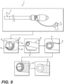
- a method of making a distal tip 80 of an expandable sheath 1 is demonstrated in the flow chart of FIG. 9 .
- the distal tip 80 can be formed on the annual member 10, outer layer 50, or on the annular member 10 and outer layer 50 combined.
- the distal tip 80 of the expandable sheath 1 is softer and more elastic than the more proximal regions of the expandable sheath 1 because it must give easily when encountering tissue to reduce the possibility of injury and it must retain the ability to expand after the sealing (reflowing) process wherein the distal tip 80 is sealed to prevent blood from entering the space between the annular member 10 and the outer layer 50.
- a first step to making the distal tip 80 is to attach a separate distal tube 82 to the distal end 5 of the expandable sheath 1, for example, by reflowing the materials together.
- the distal tube 82 can be added to the distal end 5 of the sheath 1 via specialized extrusion technology.
- the distal tube 82 is formed of, or incorporates, a material having greater elasticity than the remainder of the expandable sheath 1.
- One example material is Pebax.
- a portion of the distal tube 82 is pinched to create a longitudinally extending outer crease 84.
- the pinched portion is folded over an outer surface of the distal tube 82 in a circumferential direction, creating a longitudinally extending flap 86 that is bounded by the outer crease 84 and a longitudinally extending inner crease 85.
- the inner crease 85 of the flap 86 is cut in a longitudinal direction from the distal edge 83 of the distal tube 82 to a proximally spaced point along the longitudinal axis of the distal tube 82. This creates a longitudinally extending inner edge 87.
- the flap 86 is cut circumferentially from the outer crease 84 to the inner crease 85 at the proximally spaced point, such that the longitudinal cut of the inner crease 85 meets the circumferential cut at the proximally spaced point.
- the inner edge 87 of the flap is then extended in a circumferential direction around the outer surface 81 of the distal tube 82 and adhered to the outer surface 81.
- adhering the inner edge 87 of the flap 86 to the outer surface 81 can include covering the distal end with an outer jacket 88, then reflowing the outer jacket 88 with the distal tube 82 to form a sealed distal end.
- the outer jacket 88 is also formed of highly elastic materials.
- One example material is Neusoft.
- This outer jacket 88 can, in some embodiments, be the same layer as the outer layer 50 shown in FIGS. 2A-B . Because the flap 86 is unfolded and wrapped around the outer surface 81 before reflowing, the final wall thickness of the resulting distal tip varies minimally around its circumference.
- FIG. 10 shows an embodiment of an annular member 10 in a radially expanded state.
- the annular member 10 has a thick wall portion 162 integrally formed and coextruded with a thin wall portion 164.
- the annular member 10 shown in FIG. 10 is preferably constructed of a relatively stiff material (as compared to the outer layer 50) such as a stiff polymer like high density polyethylene (HDPE) or an equivalent polymer.
- Integral construction, such as integral extrusion, of the thick and thin wall portions 162, 164 advantageously avoids the leakage present in some conventional sheaths that use a split in the sheath to promote expandability. Other conventional sheaths tend to leak close to the proximal end where the sheath is stretched the most during passage of the prosthetic device. Also, integral construction improves the ability to torque the sheath 1.
- the thick wall portion 162 of the annular member 10 has a C-shaped cross section with a first longitudinally extending end 166 and a second longitudinally extending end 168.
- the first and second ends 166, 168 define those portions of the annular member 10 where the thickness of the thick wall portion 162 starts to narrow or otherwise transition to the thin wall portion 164 on the cross-section. That transition extends longitudinally in the direction of the longitudinal axis of the sheath 1, such that the thick wall portion 162 forms an elongate C-shaped channel.
- the thin wall portion 164 extends between the first and second ends 166, 168 of the thick wall portion 162 which together define the tubular shape of the annular member 10.
- Central lumen 138 extends longitudinally within that tubular shape.
- FIG. 10 shows the central lumen 138 in its expanded diameter which is larger than the initial diameter of the elastic outer layer 50.
- FIGS. 11 and 12 show the annular member 10 in its non-expanded, compressed or folded condition, such that the annular member 10 folded up and fit into the initial elastic lumen 158 of the elastic outer layer 50.
- the elastic outer layer 50 urges the first longitudinally extending end 166 under the second longitudinally extending end 168 of the annular member 10.
- compression and folding of the annular member 10 positions/layers the thin wall portion 164 between the first and second longitudinally extending ends 166, 168 and the overlapping sections of the thick wall portion 162.
- the foldable annular member 10 shown in FIGS. 10-12 can be formed by a coextrusion process wherein the annular member 10 is coextruded with a second, sacrificial, material while the annular member 10 is in a folded state. The second material is then removed, as described above, leaving behind the folded annular member 10.
- FIG. 13 shows a cross-section of the annular member 10 of FIGS. 10-12 during the coextrusion step.
- a tubular structure is extruded containing a first coextruded material 165 and a second coextruded material 167.
- the first coextruded material 165 defines the annular member 10, discussed above.
- the second material 167 serves to position the folded structure of the annular member 10/first material 165. When the second material 167 is removed, the first material 165 is left behind in an unexpanded, folded state.
- the first coextruded material 165 defines the elongated annular member 10 having the circumferentially extending thick wall portion 162 where the thick wall portion 162 includes the first and second longitudinally extending ends 166, 168 as described above.
- the second longitudinally extending end 168 overlaps and is exterior to the first longitudinally extending end 166 along a folded, overlapping segment 170.
- the thin wall portion 164 extends between the first and second longitudinally extending ends 166, 168 in a circumferential direction.
- the thin wall portion 164 is positioned radially farther from the central longitudinal axis of the coextruded tubular material than the first longitudinally extending end 166 and its adjacent thick wall portion 162.
- the thin wall portion 164 is positioned radially closer to the central longitudinal axis than the second longitudinally extending end 168 and its adjacent thick wall portion 162.
- the second material 167 is coextruded between and in contact with the thick and thin wall portions 162, 164, in a manner that radially spaces the thin wall portion 164 from the thick wall portion 162.
- the second material 167 can be coextruded in two separate layers/portions to form the overlapping structure of the thick and think wall portions 162, 164.
- a first layer 172 of the second material 167 is positioned between the first longitudinally extending end 166 and the thin wall portion 164, and a second layer 174 of the second material 167 is positioned between the second longitudinally extending end 168 and the thin wall portion 164.
- Each of the first and second layers 172, 174 of the second material 167 have a generally C-shape in cross section.
- the second material 167 extends circumferentially along the entire overlapping segment 170 and continues to extend away from the overlapping segment 170 in either direction, as shown in FIG. 13 , and around at least a portion of the circumference of the thick wall portion 162.
- the first layer 172 of the second material 167 extends circumferentially along the outer surface 176 of the annular member 10 and between the thin wall portion 164 and the thick wall portion 162 adjacent the first longitudinally extending end 166.
- the second layer 174 of the second material 167 extends circumferentially along the inner surface 178 of the annular member 10 and between the thin wall portion 164 and the thick wall portion 162 adjacent the second longitudinal end 168.
- first and second layer 172, 174 each extend along the circumference of the annular member 10 by about 270-degrees.
- the first and second layer 172, 174 may extend circumferentially only along the overlapping segment 170, about 45-degrees circumferentially, about 90-degrees circumferentially, about 135-degrees circumferentially, about 180-degrees circumferentially, about 225-degrees circumferentially, about 315-degrees circumferentially, or the first and second layers may extend a full 360-degrees circumferentially.
- the second material 167 has a wall thickness (measured in the radial direction) less than the thickness of the first material 165.
- the thickness of the second material 167 is uniform along the entire width of the corresponding first and second layer 172, 174, i.e., the circumferential width the first material extends along the circumference of the annular member 10. It is also contemplated, the that the thickness of the second material 167 may vary along the circumferential width of the first and second layers 172, 174.
- the second material may have a tapering thickness such that the thickness of the second material is thicker in a circumferential central position of the first and second layer 172, 174, than at the edges of the first and second layers 172, 174.
- the second material 167 can be removed.
- the second material 167 can be physically removed from the first material 165 by force, for example, by applying a force (axial and/or radial) to at least one of the first and/or second materials 165, 167.
- the second material 167 can be formed of a material that does not adhere to the first material 165 during the coextrusion process, making its physical removal relatively easy.
- the first material and second material can have different chemical properties or melting points, such that chemical or thermal treatments may be used to remove the second material 167 from the first material 165.
- first material 165 could be, or could incorporate, HDPE
- second material 167 could be, or could incorporate, nylon, polyethylene terephthalate, PA12, and/or polybutylene terephthalate, for example.
- the removal of the second material 167 enables the first longitudinal end 166 to slide relative to the second longitudinal end 168, such that the annular member 10 can be radially expanded.
- the coextrusion process used to form the sheath shown in FIG. 10 can include the formation of a taper tube 70, such as the one shown in FIG. 8 (i.e., a bump extrusion).
- Some methods include a step of covering the annular member 10 with the outer layer 50 after coextrusion.
- the outer layer 50 is formed of, or incorporates, a material with a lower elastic modulus than the annular member 10.
- a folded sheath such as the one shown in FIG. 10 offers several advantages over conventional processes.
- the process takes less time and does not necessitate the use of costly heat shrink tubes (unlike annealing operations that could be used to form the folded profile).
- a vacuum is typically needed during extrusion of the folded annular member 10 to sustain a tubular shape during the extrusion process. This does not lend itself to formation of tube having a change in diameter.
- conventional sheaths are typically formed using several thermal bonding operations to create the transition from the distally located, folded, low profile cross section to the larger cross section at the proximal end (which is formed to mate with the hub/hemostasis valve housing). These operations add time and complexity to the process and incorporate failure locations at the bond joints.
- the coextrusion process described herein can be performed without running a vacuum because the second material 167 provides support to keep the tube round during coextrusion.
Abstract
Description
- This application claims the benefit of
U.S. Provisional Application Number 62/702,993, filed July 25, 2018 - The present application is directed to a sheath for use with catheter-based technologies for repairing and/or replacing heart valves, as well as for delivering an implant, such as a prosthetic valve to a heart via the patient's vasculature.
- Endovascular delivery catheter assemblies are used to implant prosthetic devices, such as a prosthetic heart valve, at locations inside the body that are not readily accessible by surgery or where less invasive surgery is desirable. For example, aortic, mitral, tricuspid, and/or pulmonary prosthetic valves can be delivered to a treatment site using minimally invasive surgical techniques, including transcatheter delivery methods.
- An introducer sheath can be used to safely introduce a delivery apparatus into a patient's vasculature (e.g., the femoral artery). An introducer sheath generally has an elongated sleeve that is inserted into the vasculature and a housing that contains one or more sealing valves that allow a delivery apparatus to be placed in fluid communication with the vasculature with minimal blood loss. A conventional introducer sheath typically requires a tubular loader to be inserted through the seals in the housing to provide an unobstructed path through the housing for the prosthetic implant, such as a heart valve mounted on a balloon catheter. A conventional loader extends from the proximal end of the introducer sheath, and therefore decreases the available working length of the delivery apparatus that can be inserted through the sheath and into the body.
- Conventional methods of accessing a vessel, such as a femoral artery, prior to introducing the delivery system include dilating the vessel using multiple dilators or sheaths that progressively increase in diameter. This repeated insertion and vessel dilation can increase the amount of time the procedure takes, as well as the risk of damage to the vessel.
- Radially expanding intravascular sheaths reduce the overall profile of the sheath to reduce risk of damage to the vessel. Such sheaths tend to have complex mechanisms, such as ratcheting mechanisms that maintain the shaft or sheath in an expanded configuration once a device with a larger diameter than the sheath's original diameter is introduced.
- However, delivery and/or removal of prosthetic devices and other material to or from a patient still poses a risk to the patient. Furthermore, accessing the vessel remains a challenge due to the relatively large profile of the delivery system that can cause longitudinal and radial tearing of the vessel during insertion. The delivery system can additionally dislodge calcified plaque within the vessels, posing an additional risk of clots caused by the dislodged plaque. The addition of radially expanding properties can also hinder a practitioner's ability to push the sheath without it bending or kinking. Thus, there remains a need for further improvements in introducer sheaths for endovascular systems used for implanting heart valves and other prosthetic devices.
- Improved introducer sheaths are described in
U.S. Patent Application No. 14/880,109 , which is hereby incorporated by reference in its entirety. This sheath advantageously incorporates a longitudinal fold that can be unfolded to allow for radial expansion as an implant passes through. An outer, elastic tubular layer, surrounding the folded inner layer, can urge the expanded inner layer back to the folded configuration. Methods of making an inner layer with a longitudinal fold conventionally involve annealing operations to form the folded profile. The annealing operations are time consuming an require expensive heat shrink tube consumables. There are several thermal bonding operations that form the transition from folded low profile cross section to the large proximally located cross section that is required to mate with the hub/hemostasis valve housing. These operations add time, complexity, and incorporate potential failure locations at the bond joints. - Disclosed herein are expandable introducer sheaths and methods of making and using the same. The sheaths are adapted to temporarily expand a portion of the sheath to allow for the passage of a delivery system for a cardiovascular device, then return to a non-expanded state after the passage of the system. The sheath includes an elongated annular member through which the cardiovascular device and its delivery system pass. In an embodiment, the annular inner member can be formed by coextruding a first and second material. The first material includes a fold, and the second material radially spaces the different parts of the fold from each other during fabrication and provides support for maintaining the tubular structure. The second material is removed once the coextrusion process is complete.
- Disclosed herein is a method of making an expandable sheath. The method includes coextruding a first material and a second material. The first coextruded material defines an elongated annular member having a circumferentially extending thick wall portion. The thick wall portion has a first longitudinally extending end and a second longitudinally extending end. The second longitudinally extending end overlaps the first longitudinally extending end to create a folded overlapping segment. The thick wall portion of the annular member is integrally connected to a circumferentially extending thin wall portion. The thin wall portion extends between the first longitudinally extending end and the second longitudinally extending end of the thick wall portion. The first longitudinally extending end is radially closer to a central axis of the elongated annular member than the thin wall portion, and the second longitudinally extending end is radially farther from the central axis the thin wall portion.
- The second coextruded material radially spaces the thin wall portion from the thick wall portion in during the coextrusion process. After the coextrusion is finished, the second coextruded material is then removed (by force, for example). The removal of the second extruded material allows for sliding movement of the first longitudinal end relative to the second longitudinal end and radial expansion of the elongated annular member. The second coextruded material can be removed by applying a force to at least one of the first and the second coextruded materials. The second coextruded material can be removed by applying a thermal treatment to at least one of the first and the second coextruded materials. The second coextruded material can be removed by applying a chemical treatment to at least one of the first and the second coextruded materials.
- In some embodiments, the second coextruded material extends along the entire circumferential width of the overlapping segment. It can continue to extend circumferentially away from the overlapping segment. Two separate layers of the second coextruded material can be utilized. In some embodiments, a first layer of the second coextruded material is positioned between the first longitudinally extending end and the thin wall portion. In some embodiments, the first layer of the second coextruded material extends circumferentially away from the first longitudinally extending end. The first layer can extend circumferentially along an outer surface of the elongated annular member. A second layer of the second coextruded material is positioned between the second longitudinally extending end and the thin wall portion. The second layer of the second coextruded material can extend circumferentially away from the second longitudinally extending end. In some embodiments, the second layer of the second coextruded material extends circumferentially along an inner surface of the elongated annular member.
- In some embodiments, the second coextruded material extends along an inner surface and an outer surface of the elongated member. The second coextruded material can extend around the entire circumference of the inner surface of the elongated member. The second coextruded material can also extend around the entire circumference of the outer surface of the elongated member.
- In some embodiments of the method, a taper tube is coextruded near the proximal end of the annular member. The taper tube can have a diameter greater than a diameter of the elongated member. The taper tube is added as part of the coextrusion process, and therefore does not require the use of bonding processes (e.g., thermal bonding, chemical bonding, mechanical bonding). Finally, the annular member can be covered by an elastic outer layer which returns the annular member to a folded configuration after expansion (for example, after an implant passes through).
- In the drawings, like reference numbers and designations in the various drawings indicate like elements.
-
Fig. 1 is an elevation view of an expandable sheath along with an endovascular delivery system for implanting a prosthetic heart valve. -
FIG. 2A shows a cross sectional view of an example expandable sheath in the non-expanded state. -
FIG. 2B shows the expandable sheath ofFIG. 2A in the expanded state. -
FIG. 3A shows a cross sectional view of an example expandable sheath in the non-expanded state. -
FIG. 3B shows the expandable sheath ofFIG. 3A in the expanded state. -
FIG. 4A shows a cross sectional view of an example expandable sheath in the non-expanded state. -
FIG. 4B shows the expandable sheath ofFIG. 4A in the expanded state. -
FIG. 5A shows a cross sectional view of an example expandable sheath in the non-expanded state. -
FIG. 5B shows the expandable sheath ofFIG. 5A in the expanded state. -
FIG. 6A shows a cross sectional view of an example an expandable sheath in the non-expanded state. -
FIG. 6B shows the expandable sheath ofFIG. 6A in the expanded state. -
FIG. 7A shows a cross sectional view of an example expandable sheath during an intermediate processing step. -
FIG. 7B shows the expandable sheath ofFIG. 7A in a non-expanded state, after removal of a sacrificial material. -
FIG. 7C shows the expandable sheath ofFIG. 7B in the expanded state. -
FIG. 8 shows a perspective view of an expandable sheath. -
FIG. 9 shows a method of making a distal tip of an expandable sheath. -
FIG. 10 is a cross sectional view of an embodiment of the inner tubular layer of an example sheath in the expanded state. -
FIG. 11 is a cross sectional view of both the inner and outer tubular layers of the example sheath ofFIG. 10 . In this example, the inner tubular layer is in the compressed condition. -
FIG. 12 is a perspective view of the distal end of the example sheath ofFIG. 10 . -
FIG. 13 is a cross sectional view of the inner tubular layer ofFIG. 10 during an intermediate processing step. - The following description of certain examples of the inventive concepts should not be used to limit the scope of the claims. Other examples, features, aspects, embodiments, and advantages will become apparent to those skilled in the art from the following description. As will be realized, the device and/or methods are capable of other different and obvious aspects, all without departing from the spirit of the inventive concepts. Accordingly, the drawings and descriptions should be regarded as illustrative in nature and not restrictive.
- For purposes of this description, certain aspects, advantages, and novel features of the embodiments of this disclosure are described herein. The described methods, systems, and apparatus should not be construed as limiting in any way. Instead, the present disclosure is directed toward all novel and nonobvious features and aspects of the various disclosed embodiments, alone and in various combinations and sub-combinations with one another. The disclosed methods, systems, and apparatus are not limited to any specific aspect, feature, or combination thereof, nor do the disclosed methods, systems, and apparatus require that any one or more specific advantages be present or problems be solved.
- Features, integers, characteristics, compounds, chemical moieties, or groups described in conjunction with a particular aspect, embodiment or example of the invention are to be understood to be applicable to any other aspect, embodiment or example described herein unless incompatible therewith. All of the features disclosed in this specification (including any accompanying claims, abstract, and drawings), and/or all of the steps of any method or process so disclosed, may be combined in any combination, except combinations where at least some of such features and/or steps are mutually exclusive. The invention is not restricted to the details of any foregoing embodiments. The invention extends to any novel one, or any novel combination, of the features disclosed in this specification (including any accompanying claims, abstract, and drawings), or to any novel one, or any novel combination, of the steps of any method or process so disclosed.
- It should be appreciated that any patent, publication, or other disclosure material, in whole or in part, that is said to be incorporated by reference herein is incorporated herein only to the extent that the incorporated material does not conflict with existing definitions, statements, or other disclosure material set forth in this disclosure. As such, and to the extent necessary, the disclosure as explicitly set forth herein supersedes any conflicting material incorporated herein by reference. Any material, or portion thereof, that is said to be incorporated by reference herein, but which conflicts with existing definitions, statements, or other disclosure material set forth herein will only be incorporated to the extent that no conflict arises between that incorporated material and the existing disclosure material.
- As used in the specification and the appended claims, the singular forms "a," "an" and "the" include plural referents unless the context clearly dictates otherwise. Ranges may be expressed herein as from "about" one particular value, and/or to "about" another particular value. When such a range is expressed, another aspect includes from the one particular value and/or to the other particular value. Similarly, when values are expressed as approximations, by use of the antecedent "about," it will be understood that the particular value forms another aspect. It will be further understood that the endpoints of each of the ranges are significant both in relation to the other endpoint, and independently of the other endpoint.
- "Optional" or "optionally" means that the subsequently described event or circumstance may or may not occur, and that the description includes instances where said event or circumstance occurs and instances where it does not.
- Throughout the description and claims of this specification, the word "comprise" and variations of the word, such as "comprising" and "comprises," means "including but not limited to," and is not intended to exclude, for example, other additives, components, integers or steps. "Exemplary" means "an example of' and is not intended to convey an indication of a preferred or ideal aspect. "Such as" is not used in a restrictive sense, but for explanatory purposes.
- Disclosed herein are expandable introducer sheaths and methods of making and using the same. As will be described in further detail below, the
expandable sheaths 1 are adapted to allow for temporary expansion of a portion of the sheath to accommodate the passage of a delivery system for a cardiovascular device, then return to a non-expanded state, or "recover" after the passage of the delivery system and device. -
FIG. 1 illustrates asheath 1 according to the present disclosure in use with arepresentative delivery apparatus 210 for delivering aprosthetic device 212, such as a tissue heart valve, to a patient. Theapparatus 210 can include a steerable guide catheter 214 (also referred to as a flex catheter), aballoon catheter 216 extending through theguide catheter 214, and anose catheter 218 extending through theballoon catheter 216. Theguide catheter 214, theballoon catheter 216, and thenose catheter 218 in the illustrated embodiment are adapted to slide longitudinally relative to each other to facilitate delivery and positioning of thevalve 212 at an implantation site in a patient's body, as described in detail below. Generally, asheath 1 is inserted into a vessel, such as the transfemoral vessel, passing through the skin of patient, such that the distal end of thesheath 1 is inserted into the vessel.Sheath 1 can include a hemostasis valve at the opposite, proximal end of the sheath. Thedelivery apparatus 210 can be inserted into thesheath 1, and theprosthetic device 212 can then be delivered and implanted within patient. - The
expandable introducer sheath 1 is adapted to allow for temporary radial expansion of a portion of the sheath to accommodate the passage of a delivery system for a cardiovascular device (e.g., prosthetic heart valve 212) and to then return to a non-expanded state after the passage of the delivery system with its prosthetic device. Theexpandable sheath 1 includes an elongatedannular member 10 through which the delivery system andprosthetic heart valve 212 pass. As will be described in more detail below, theannular member 10 of theexpandable sheath 1 can include longitudinally extendingchannels prosthetic heart valve 212. Thechannels annular member 10 certain contact surfaces 22, 24 are brought into contact with adjacent surfaces of thedelivery apparatus 210, thereby reducing friction between theannular member 10 and the passing structure. In some embodiments, the radial expansion of the expandableannular member 10 at any given portion along its length is due to the ability ofbase 20 and/orbridge members 30 of theannular member 10 to rotate. The rotation of these sections reduces the surface/contact area of theannular member 10 thereby reducing friction with the passing structure. Theexpandable sheath 1 can include an elasticouter layer 50. In some embodiments, theouter layer 50 can compress theannular member 10 towards a non-expanded configuration. -
FIGS. 2A and 2B show a cross-section of an exampleexpandable sheath 1 in an expanded (FIG. 2A ) and a non-expanded (FIG. 2B ) state. Thenon-expanded sheath 1 includes an innerannular member 10 and anouter layer 50. Theouter layer 50 can be constructed from an elastic material that allows for temporary radial expansion of a portion of theouter layer 50 corresponding to the temporary radial expansion of theannular member 10 to accommodate the passage of the delivery system for a cardiovascular device (e.g., prosthetic heart valve 212). After passage of the delivery system with its prosthetic device, theannular member 10 andouter layer 50 return to a non-expanded state (FIG. 2B ). As illustrated inFIG. 2A , theannular member 10 includes a plurality ofbase members 20 arranged around the circumference of theannular member 10 andbridge members 30 extending between opposing pairs of base members 20 (e.g.,base member 20a andbase member 20b). As illustrated inFIG. 2A , thebase members 20 can define a rectilinear shape in cross-section. Thebase members 20 can include an outer edge that define the outer surface/diameter 16 of theannular member 10 and an inner edge that define the inner surface/diameter 18 when theannular member 10 is in a non-expanded state.Base members 20 can includeside walls 15 that extend radially between the inner and outer edges. As illustrated inFIG. 2A , the outer edge has a longer length (around the circumference of the annular member 10) than the inner edge. Theside walls 15 can meet the inner and outer edges at a curve (illustrated) or angle. Theside walls 15 can terminate at thebridge member 30. As provided inFIG. 2A , theside walls 15 can meet thebridge members 30 at a curve. In other example annular members 10 (see e.g.,FIG. 6A ) the side wall of thebase member 20 can meet thebridge member 30 at a straight or angled edge/joint. It is further contemplated that thebase members 20 can define any regular or irregular shape in cross-section including, for example, square, rectangle, trapezoidal, circular, and oval. Likewise,bridge members 30 can define any regular or irregular shape. As provided inFIG. 2A , in the unexpanded state thebridge members 30 define a generally S-shape cross-section. That is, in cross-section, thebridge members 30 ofFIG. 2A can include a relatively (radially) elongate shape that extends between bends (at joints 32) where thebridge member 30 couples to theadjacent base member 20. The bends bracket the ends of the elongate portion and serve as the connection to either the radially inward corner or radially outward corner of adjacent base members. The elongate portion of thebridge member 30 can also widen in the outward radial direction. As will be explained in more detail below, during expansion of theannular member 10 the shape of thebase member 20 and/orbridge member 30 changes or otherwise deforms. - As illustrated in
FIG. 2A , in the non-expanded state, theannular member 10 includes longitudinally extendingchannels channels 12 extend radially inward from the outer surface/diameter 16 of theannular member 10 towards itslongitudinal axis 11. The inward extendingchannels 12 are defined between abase member 20 and anadjacent bridge member 30. The outward extendingchannels 14 extend radially outward from the inner surface/diameter 18 of theannular member 10 in a radial direction away from thelongitudinal axis 11 and are similarly defined between abase member 20 and anadjacent bridge member 30. - The inward and outward extending
channels channel 12 is positioned circumferentially between two outward extendingchannels 14, each outward extendingchannel 14 is positioned circumferentially between two inward extending channels 12). - As depicted in
FIG. 2A , the inward and outward extendingchannels longitudinal axis 11 of theannular member 10. For example, the centerline (c) of each of the inward and outward extendingchannels annular member 10 proximate the opening of the channel. - The inward and outward extending
channels annular member 10. For example, as illustrated inFIG. 2A , the inward and outward extendingchannels annular member 10. Though not illustrated, it is contemplated that the depth of the inward and outward extendingchannels annular member 10. - The inward and outward extending
channels bridge member 30 andbase member 20, i.e., betweenside wall 13 andside wall 15. As illustrated inFIG. 2A , the width (w) of each channel can be uniform around theannular member 10. It is also contemplated that the width (w) of different channels can vary around the circumference of theannular member 10. The width (w) of the inward and outward extendingchannels FIG. 2A ) or vary along the depth (d) of the channel. For example, the width (w) of the channel can increase in a direction from the center of theannular member 10 towards the perimeter of theannular member 10. - The shape of the inward and outward extending
channels annular member 10. As depicted inFIG. 2A , each of the inward and outward extendingchannels side wall 13 and side wall 15) that terminate at arounded end 19. It is contemplated that the shape of inward and outward extendingchannels channel annular member 10. - In the embodiment shown in
FIG. 2A , the inward and outward extendingchannels annular member 10 and are similar in size and shape. While it is contemplated that the size and spacing of thebase members 20,bridge members 30 and corresponding inward and outward extendingchannels annular member 10 during expansion. For example, during expansion (shown inFIG. 2B ) tension is distributed to many points around the circumference of theannular member 10 and not focused at a single location. This distribution of tension reduces the risk of tearing theannular member 10. - As described above, the
annular member 10 and elasticouter layer 50 of thesheath 1 are designed to locally expand as theprosthetic device 212 is passed through the interior lumen of thesheath 1 and then substantially return to their original shape once the prosthetic device has passed through that portion of thesheath 1. That is, in the non-expanded state the outer diameter of theannular member 10 andouter layer 50 can be substantially constant across the length of thesheath 1 from theproximal end 3 to thedistal end 5. As theprosthetic device 212 passes through the interior lumen of thesheath 1, the portion of theannular member 10 andouter layer 50 proximate theprosthetic device 212 expand radially, with the remaining length/portion of theannular member 10 andouter layer 50 in a substantially non-expanded state. Once the device has passed through a portion of the lumen of thesheath 1, that portion of thesheath 1 can substantially return to its original shape and size.FIG. 2B illustrates theannular member 10 andouter layer 50 in an expanded state. In the expanded state the outer diameters of theannular member 10 and elasticouter layer 50 are greater than the non-expanded diameters of theannular member 10 andouter layer 50. - To achieve expansion, the orientation of the
base members 20 andbridge members 30 changes. As illustrated inFIG. 2B , thebase members 20 rotate during expansion of theannular member 10. For example, thebase members 20 rotate with respect to the central axis of eachcorresponding base member 20. Similarly, thebridge members 30 rotate and flex atjoints 32 to extend in a direction around the circumference of theannular member 10, thereby increasing the circumferential distance/spacing betweenadjacent base members 20 and widening/changing the shape of each of the intervening inward and outward extendingchannels bridge members 30 can be constructed from a flexible material to accommodate flexing atjoints 32 and/or lengthening/deformation during expansion of theannular member 10 and then substantially return to the original, non-expanded shape/configuration. Thebase members 20 can be constructed from a same or different material than thebridge members 30. Accordingly, it is also contemplated that thebase members 20 can flex and deform during expansion and contraction of theannular member 10. - As illustrated in
FIG. 2B , in the expanded state the orientation of thebase members 20 andbridge members 30 changes. Contact surfaces 22, 24 provided on thebase members 20 now define the inner and outer diameters of theannular member 10, respectively. In the expanded state, the contact surfaces 24 define the inner diameter of theouter layer 50. The contact surfaces 22 extend towards the interior of theannular member 10 and reduce the contact surface area between theannular member 10 and the passing device, thereby lowering the coefficient of friction/resistance between theinner surface 18 of theannular member 10 and the passing device. The contact surfaces 22, 24 can define rounded/curved ends 26 or linear/angled ends 28 when viewed in cross-section. For example, the contact surfaces 22, 24 of the expanded embodiments shown inFIGS. 2B ,3B ,4B ,5B and 6C include rounded ends 26 in cross-section. In another example, the expanded annular member depicted inFIG. 7B includes both angled ends 28 and rounded ends 26 at the contact surfaces 22, 24. Referring back toFIG. 2B , the shape of the rounded ends 26, including the radii of curvature, can be constant across allbase members 20 of theannular member 10. It is also contemplated that the shape of the rounded ends 26/contact surfaces 22, 24 may vary betweenbase members 20, and vary betweencontact surface 22 andcontact surface 24 of thesame base member 20. - In transition back to the non-expanded state, the
base members 20 andbridge members 30 move back to their original configuration/orientation. The transition back to the non-expanded state can be facilitated by the inclusion of an elasticouter layer 50 that extends over the elongatedannular member 10. Theouter layer 50 comprises a material having a lower elastic modulus than theannular member 10, which enables theouter layer 50 to force theannular member 10 back into the non-expanded state after passage of the cardiovascular device. Theannular member 10 can be made of a more lubricious material than theouter layer 50. For example, theouter layer 50 can be made of, or incorporate, polyurethane, silicone, and/or rubber, and theannular member 10 can be made of, or incorporate, high density polyethylene, polytetrafluoroethylene, and/or other fluoropolymers. -
FIGS. 3A and 3B depict anotherexample sheath 1 including anannular member 10 and elasticouter layer 50. Theannular member 10 has a plurality ofbase members 20 arranged around the circumference of theannular member 10 andbridge members 30 extending between opposing pairs ofbase members 20. As illustrated inFIG. 3A , thebase members 20 andbridge members 30 can define a curvilinear shape in cross-section. For example, as depicted inFIG. 3A , thebase member 20 can define an elongated portion extending around the outer surface/diameter 16 of the annular member and terminating in arounded end 26contact surface 24, the elongated portion of thebase member 20 defining the outer diameter of theannular member 10 in the non-expanded state. Thebridge 30 can define an elongated member having substantially linear and parallel sides and terminating at a curved end proximate the inner surface/diameter 18 of theannular member 10, the curved end surface of thebridge 30 defining the inner diameter of theannular member 10 in the non-expanded state. - Similar to the
annular member 10 depicted inFIG. 2A , in the non-expanded state theannular member 10 ofFIG. 3A includes longitudinally extendingchannels bridge member 30 andadjacent base member 20 alternating in inward versus outward directionality around the circumference of theannular member 10. The inward extendingchannels 12 extend inward from the outer surface/diameter 16 of theannular member 10 and the outward extendingchannels 14 extend outward from the inner surface/diameter 18 of theannular member 10. The inward and outward extendingchannels outer surface annular member 10 proximate the opening of the channel). - As described above, the
annular member 10 and the elasticouter layer 50 of thesheath 1 are designed to locally expand in a radial direction between a non-expanded and an expanded state as theprosthetic device 212 is passed through the interior lumen of thesheath 1.FIG. 3B illustrates theannular member 10 andouter layer 50 in an expanded state. The orientation and/or shape of thebase members 20 andbridge members 30 of theannular member 10 change during expansion. As illustrated inFIG. 3B , thebase members 20 extend and elongate in a direction around the circumference of theannular member 10 when transitioned to the expanded state. Thebridge members 30 change in orientation during expansion. In the non-expanded state thebridge members 30 extend is a direction toward/angled with respect to thelongitudinal axis 11/the interior of theannular member 10. Upon expansion of theannular member 10 thebridge members 30 rotate, elongate and/or extend in a direction around the circumference of theannular member 10. For example, thebridge members 30 can flex atjoints 32 to facilitate their change in orientation with respect to thebase members 20. Upon expansion of theannular member 10, the distance/spacing betweenadjacent base members 20 increases, widening and changing the shape of the intervening inward and outward extendingchannels annular member 10 and theouter layer 50. - As illustrated in
FIG. 3B , in the expanded state the contact surfaces 22 provided on thebase member 20 and/orbridge member 30 define the inner diameter of theannular member 10. Likewise, thecontact surface 24 defines the outer diameter of theannular member 10, and the corresponding inner diameter of theouter layer 50 in the expanded state. The outside surface of theouter layer 50 defines the outermost diameter of the combinedannular member 10/outer layer 50. Contact surfaces 22 reduce the contact surface area between theannular member 10 and the passing device, thereby lowering the coefficient of friction/resistance between theinner surface 18 and the passing device. -
FIGS. 4A and 4B depict anexample sheath 1 including anannular member 10 and elasticouter layer 50. Theannular member 10 has fourbase members 20 arranged around the circumference of theannular member 10 and fourcorresponding bridge members 30 extending between opposing pairs ofbase members 20. In the non-expanded state, thebase members 20 andbridge members 30 can define a curvilinear shape in cross-section. For example, as depicted inFIG. 4A , thebase members 20 can define two arcuate portions having substantially similar shape terminating in two substantially linear portions extending in a radial direction with respect to theannular member 10. In the non-expanded state, the arcuate portions of thebase members 20 define the inner and outer diameter of theannular member 10. In the non-expanded state, thebridge members 30 can define an S-shape in cross-section. - Similar to the
annular member 10 depicted inFIGS. 2A and3A , in the non-expanded state theannular member 10 ofFIG. 4A includes longitudinally extendingchannels bridge member 30 andadjacent base member 20 alternating in inward versus outward directionality around the circumference of theannular member 10. The inward and outward extendingchannels longitudinal axis 11 of theannular member 10. For example, the centerline of each of the inward and outward extendingchannels annular member 10 proximate the opening of the channel. - As described above, the
annular member 10 and the elasticouter layer 50 are designed to locally expand in a radial direction between a non-expanded and an expanded state as theprosthetic device 212 is passed through the interior lumen of thesheath 1.FIG. 4B illustrates theannular member 10 andouter layer 50 in an expanded state. The orientation and/or shape of thebase members 20 andbridge members 30 of theannular member 10 change during expansion. As illustrated inFIG. 4B , thebase members 20 extend and/or elongate in a direction around the circumference of theannular member 10 when transitioned to the expanded state. Thebridge members 30 also change in orientation and/or shape during expansion. In the non-expanded state thebridge members 30 extend is a direction toward thelongitudinal axis 11/the interior of theannular member 10. Upon expansion of theannular member 10 thebridge members 30 rotate, elongate and/or extend in a direction around the circumference of theannular member 10. For example, thebridge members 30 can flex atjoints 32 to facilitate their change in orientation with respect to thebase members 20. Upon expansion of theannular member 10, the distance/spacing between adjacent base members 20 increases, widening and changing the shape of the intervening inward and outward extendingchannels outer layer 50. - As illustrated in
FIG. 4B , in the expanded state the contact surfaces 22 provided on thebase members 20 define the inner diameter of theannular member 10. Likewise, thecontact surface 24 defines the outer diameter of theannular member 10, and the corresponding inner diameter of theouter layer 50 in the expanded state. It is contemplated that a portion of theinner surface 16 andouter surface 18 of thebase member 20 can also define the inner and outer diameter of theannular member 10 in the expanded state. Contact surfaces 22 reduce the contact surface area between theannular member 10 and the passing device, thereby lowering the coefficient of friction/resistance between the annular member and the passing device. -
FIGS. 5A and 5B depict anotherexample sheath 1 including anannular member 10 and elasticouter layer 50. Theannular member 10 has eighteenbase members 20 arranged around the circumference of theannular member 10 and eighteen correspondingbridge members 30 extending between opposing pairs ofbase members 20. In the non-expanded state, thebase members 20 andbridge members 30 can define a curvilinear shape in cross-section. For example, as depicted inFIG. 5A , thebase members 20 can define a semi-rectangular shape. Thebridge members 30 can define an S-shape in cross-section. - Similar to the
annular members 10 depicted inFIGS. 2A ,3A and4A , in the non-expanded state theannular member 10 ofFIG. 5A includes longitudinally extendingchannels bridge member 30 andadjacent base member 20 alternating in inward versus outward directionality around the circumference of theannular member 10. The inward and outward extendingchannels longitudinal axis 11 of theannular member 10. For example, the centerline of each of the inward and outward extendingchannels annular member 10 proximate the opening of the channel. - As described above, the
annular member 10 and the elasticouter layer 50 are designed to locally expand in a radial direction between a non-expanded and an expanded state as theprosthetic device 212 is passed through the inner lumen of thesheath 1.FIG. 5B illustrates theannular member 10 andouter layer 50 in an expanded state. The orientation and/or shape of thebase members 20 andbridge members 30 of theannular member 10 change during expansion. As illustrated inFIG. 5B , thebase members 20 extend and/or elongate in a direction around the circumference of theannular member 10 when transitioned to the expanded state. Thebridge members 30 also change in orientation and/or shape during expansion. In the non-expanded state thebridge members 30 extend in a direction toward thelongitudinal axis 11/the interior of theannular member 10. Upon expansion of theannular member 10 thebridge members 30 rotate, elongate and/or extend in a direction around the circumference of theannular member 10. For example, thebridge members 30 can flex atjoints 32 to facilitate their change in orientation with respect to thebase members 20. Upon expansion of theannular member 10, the distance/spacing betweenadjacent base members 20 increases, widening and changing the shape of the intervening inward and outward extendingchannels annular member 10 and theouter layer 50. - As illustrated in
FIG. 5B , in the expanded state the contact surfaces 22 provided on thebase members 20 define the inner diameter of theannular member 10. Likewise, thecontact surface 24 defines the outer diameter of theannular member 10, and the corresponding inner diameter of theouter layer 50 in the expanded state. Contact surfaces 22 reduce the contact surface area between theannular member 10 and the passing device, thereby lowering the coefficient of friction/resistance between the annular member and the passing device. -
FIGS. 6A and 6B depict anotherexample sheath 1 including anannular member 10 and elasticouter layer 50. Theannular member 10 hasbase members 20 arranged around the circumference of theannular member 10 and correspondingbridge members 30 extending between opposing pairs ofbase members 20. - In the non-expanded state, the
base members 20 andbridge members 30 can define a curvilinear shape in cross-section. For example, as depicted inFIG. 6A , thebase members 20 define a wedge shape. Thebridge members 30 define an arcuate/curved shape in cross-section. - Similar to the
annular members 10 depicted inFIGS. 2A ,3A ,4A and5A , in the non-expanded state theannular member 10 ofFIG. 6A includes longitudinally extendingchannels bridge member 30 andadjacent base member 20 alternating in inward versus outward directionality around the circumference of theannular member 10. The inward and outward extendingchannels longitudinal axis 11 of theannular member 10. For example, the centerline of each of the inward and outward extendingchannels annular member 10 proximate the opening of the channel. The shape, in cross-section, of the inward and outward extendingchannels FIG. 6A can include two substantially parallel and straight sides (defined byside wall 13 and side wall 15) that terminate at arounded end 19. Therounded end 19 can have a width/diameter greater than the width (w) of the corresponding inward and outward extendingchannels - As described above, the
annular member 10 and the elasticouter layer 50 of thesheath 1 are designed to locally expand in a radial direction between a non-expanded and an expanded state as the prosthetic device 112 is passed through the interior lumen of thesheath 1.FIG. 6B illustrates theannular member 10 andouter layer 50 in an expanded state. The orientation and/or shape of thebase members 20 andbridge members 30 of theannular member 10 change during expansion. As illustrated inFIG. 6B , thebase members 20 rotate, extend and/or elongate in a direction around the circumference of theannular member 10 when transitioned to the expanded state. For example, thebase members 20 can rotate with respect to the central axis of eachcorresponding base member 20. Similarly, thebridge members 30 also change in orientation and/or shape during expansion. In the non-expanded state thebridge members 30 define an arcuate shape that flexes to increase in radius/length upon expansion of theannular member 10. It is also contemplated that thebridge members 30 can rotate, elongate and/or extend in a direction around the circumference of theannular member 10 upon expansion. Upon expansion of theannular member 10, the distance/spacing betweenadjacent base members 20 increases, widening and changing the shape of the intervening inward and outward extendingchannels annular member 10 and theouter layer 50. The wall thickness of theannular member 10 is thinner at thebridge members 30 than compared to thebase members 20. The decreased thickness at thebridge members 30 eases the bending of thebridge members 30 during expansion, lessening the chance of fracture. - As illustrated in
FIG. 6B , in the expanded state the contact surfaces 22 provided on thebase members 20 define the inner diameter of theannular member 10. Likewise, thecontact surface 24 defines the outer diameter of theannular member 10, and the corresponding inner diameter of theouter layer 50 in the expanded state. Contact surfaces 22 reduce the contact surface area between theannular member 10 and the passing device, thereby lowering the coefficient of friction/resistance between the annular member and the passing device. - As illustrated in
FIGS. 2A ,3A ,4A ,5A ,6A and7A , the size, shape, spacing and number of channels can vary. For example, the non-expanded embodiments ofFIGS. 2A andFIG. 7B have twenty four combined inward and outward extendingchannels FIG. 3A andFIG. 6A have twenty combined inward and outward extendingchannels FIG. 4A has eight combined inward and outward extendingchannels FIG. 5A has thirty six combined inward and outward extendingchannels - Sheaths of the present disclosure can be used with various methods of introducing a prosthetic device into a patient's vasculature. Generally, during use, the
expandable sheath 1 is passed through the skin of patient (usually over a guidewire) such that the distal end region of theexpandable sheath 1 is inserted into a vessel, such as a femoral artery, and then advanced to a wider vessel, such as the abdominal aorta. Thedelivery apparatus 210 is then inserted through theexpandable sheath 1. The prosthetic device is then delivered to the implantation site and implanted within the patient. During the advance of the prosthetic device through theexpandable sheath 1, the device and its delivery system exerts a radially outwardly directed force on the portion of theannular member 10, theannular member 10 exerts a corresponding radially outwardly directed force on theouter layer 50, causing both theannular member 10 and theouter layer 50 to expand locally to accommodate the profile of the device. The expansion of theannular member 10 widens thelongitudinally extending channels outer surfaces annular member 10. - As the prosthetic device and its delivery system passes through the
expandable sheath 1, theexpandable sheath 1 recovers. That is, it returns to its original, non-expanded configuration. In some embodiments, this is facilitated byouter layer 50, which has a lower elastic modulus thanannular member 10. Theouter layer 50 moves the contact surfaces 22, 24 of theannular member 10 away from the inner and outer surfaces after the passage of theprosthetic valve 212. - As described above, the
expandable sheath 1 can be used to deliver, remove, repair, and/or replace a prosthetic device. In one example, theexpandable sheath 1 described above can be used to deliver a tissue heart valve to a patient. For example, a tissue heart valve (in a crimped state) can be placed on the distal end portion of an elongated delivery apparatus and inserted into the sheath. Next, the delivery apparatus and crimped heart valve can be advanced through the patient's vasculature to the treatment site, where the valve is implanted. - Beyond transcatheter heart valves, the
expandable sheath 1 can be useful for other types of minimally invasive surgery, such as any surgery requiring introduction of an apparatus into a subject's vessel. For example, theexpandable sheath 1 can be used to introduce other types of delivery apparatus for placing various types of intraluminal devices (e.g., stents, stented grafts, balloon catheters for angioplasty procedures, etc.) into many types of vascular and non-vascular body lumens (e.g., veins, arteries, esophagus, ducts of the biliary tree, intestine, urethra, fallopian tube, other endocrine or exocrine ducts, etc.). -
FIGS. 7A-7C show cross-sections of anexpandable sheath 1 including anannular member 10 andouter layer 50 similar to theannular member 10 andouter layer 50 depicted inFIGS. 2A and 2B .FIG. 7A shows a cross-sections of anexpandable sheath 1 during an intermediate processing step that includes a second material in addition to the material used to form theannular member 10. During processing, a tube is coextruded containing afirst material 60 and asecond material 62. Thefirst material 60 defines theannular member 10 discussed above. Thesecond material 62 does not adhere to thefirst material 60 and defines a first and second set of longitudinally extendingribbons second material 62 could be, or could incorporate, nylon, polyethylene terephthalate, and/or polybutylene terephthalate, for example. The first and second set ofribbons channels annular member 10 during the extrusion process. The first set ofribbons 64 extends inwardly from theouter surface 16 toward theinner surface 18 of theannular member 10, and the second set ofribbons 66 extends outwardly from theinner surface 18 toward theouter surface 16 of theannular member 10. Each ribbon of a selected set is positioned circumferentially between two ribbons of the other set. - In some embodiments, the
second material 62 is a sacrificial material. For example, theribbons second material 62 shown inFIG. 7A are removed after coextrusion, exposing thelongitudinally extending channels FIG. 7B . - However, some embodiments, such as the one shown in
FIG. 6A , thefirst material 60 andsecond material 62 of theannular member 10 are coextruded with athird material 68. Thisthird material 68 is in contact with a portion of thefirst material 60 and a portion of thesecond material 62, and adheres to both the first andsecond materials third material 68, thesecond material 62 is not removed. However, it still does not adhere tofirst material 60. Instead, thethird material 68 acts as a tie layer to hold the first andsecond materials annular member 10. This eliminates the need to remove theribbons second material 62 prior to use, while still allowing a widening of a channel between the non-adherent first 60 and second 62 materials during the expansion of theannular member 10. The retention of thesecond material 62 also increases the torque of the finished sheath, so that a user finds it easier to twist the sheath. - Some methods include a step of covering the
annular member 10 with theouter layer 50 after coextrusion. As discussed above, theouter layer 50 is formed of, or incorporates, a material with a lower elastic modulus than theannular member 10. -
FIG. 8 shows a perspective view of anexample sheath 1. In this view, only theouter layer 50 is visible. Thesheath 1 comprises aproximal end 3 anddistal end 5 opposite theproximal end 3. Thesheath 1 can comprise a hemostasis valve inside the lumen of thesheath 1, at or near theproximal end 3. Thesheath 1 can include ataper tube 70, a flared proximal end. In some embodiments of the method of making, thetaper tube 70 is added to the coextrusion. The addition of thesecond material 62 will stabilize the coextrusion process and make it possible to add ataper tube 70 during extrusion. This is advantageous because it makes it possible to eliminate the typical taper tube manufacturing steps of flaring (increasing the inner diameter of the sheath) and bonding (increasing the wall thickness after flaring). - Additionally, the
sheath 1 can comprise a softdistal tip 80 at thedistal end 5. Thesoft tip 80 can be provided with a lower hardness than the other portions of thesheath 1. In addition to the method of making the expandable sheath described above, a method of making adistal tip 80 of anexpandable sheath 1 is demonstrated in the flow chart ofFIG. 9 . Thedistal tip 80 can be formed on theannual member 10,outer layer 50, or on theannular member 10 andouter layer 50 combined. Thedistal tip 80 of theexpandable sheath 1 is softer and more elastic than the more proximal regions of theexpandable sheath 1 because it must give easily when encountering tissue to reduce the possibility of injury and it must retain the ability to expand after the sealing (reflowing) process wherein thedistal tip 80 is sealed to prevent blood from entering the space between theannular member 10 and theouter layer 50. A first step to making thedistal tip 80 is to attach a separatedistal tube 82 to thedistal end 5 of theexpandable sheath 1, for example, by reflowing the materials together. Alternatively, thedistal tube 82 can be added to thedistal end 5 of thesheath 1 via specialized extrusion technology. Thedistal tube 82 is formed of, or incorporates, a material having greater elasticity than the remainder of theexpandable sheath 1. One example material is Pebax. - Next, a portion of the
distal tube 82 is pinched to create a longitudinally extendingouter crease 84. The pinched portion is folded over an outer surface of thedistal tube 82 in a circumferential direction, creating alongitudinally extending flap 86 that is bounded by theouter crease 84 and a longitudinally extendinginner crease 85. Theinner crease 85 of theflap 86 is cut in a longitudinal direction from thedistal edge 83 of thedistal tube 82 to a proximally spaced point along the longitudinal axis of thedistal tube 82. This creates a longitudinally extendinginner edge 87. Theflap 86 is cut circumferentially from theouter crease 84 to theinner crease 85 at the proximally spaced point, such that the longitudinal cut of theinner crease 85 meets the circumferential cut at the proximally spaced point. Theinner edge 87 of the flap is then extended in a circumferential direction around theouter surface 81 of thedistal tube 82 and adhered to theouter surface 81. - In some embodiments, such as the one shown in
FIG. 9 , adhering theinner edge 87 of theflap 86 to theouter surface 81 can include covering the distal end with an outer jacket 88, then reflowing the outer jacket 88 with thedistal tube 82 to form a sealed distal end. The outer jacket 88 is also formed of highly elastic materials. One example material is Neusoft. This outer jacket 88 can, in some embodiments, be the same layer as theouter layer 50 shown inFIGS. 2A-B . Because theflap 86 is unfolded and wrapped around theouter surface 81 before reflowing, the final wall thickness of the resulting distal tip varies minimally around its circumference. -
FIG. 10 shows an embodiment of anannular member 10 in a radially expanded state. Theannular member 10 has athick wall portion 162 integrally formed and coextruded with athin wall portion 164. Theannular member 10 shown inFIG. 10 is preferably constructed of a relatively stiff material (as compared to the outer layer 50) such as a stiff polymer like high density polyethylene (HDPE) or an equivalent polymer. Integral construction, such as integral extrusion, of the thick andthin wall portions sheath 1. - The
thick wall portion 162 of theannular member 10, as in the illustrated embodiment ofFIG. 10 , has a C-shaped cross section with a firstlongitudinally extending end 166 and a secondlongitudinally extending end 168. The first and second ends 166, 168 define those portions of theannular member 10 where the thickness of thethick wall portion 162 starts to narrow or otherwise transition to thethin wall portion 164 on the cross-section. That transition extends longitudinally in the direction of the longitudinal axis of thesheath 1, such that thethick wall portion 162 forms an elongate C-shaped channel. - The
thin wall portion 164 extends between the first and second ends 166, 168 of thethick wall portion 162 which together define the tubular shape of theannular member 10.Central lumen 138 extends longitudinally within that tubular shape.FIG. 10 , in particular, shows thecentral lumen 138 in its expanded diameter which is larger than the initial diameter of the elasticouter layer 50. -
FIGS. 11 and 12 show theannular member 10 in its non-expanded, compressed or folded condition, such that theannular member 10 folded up and fit into the initialelastic lumen 158 of the elasticouter layer 50. In the compressed condition, the elasticouter layer 50 urges the first longitudinally extendingend 166 under the secondlongitudinally extending end 168 of theannular member 10. As illustrated inFIGS. 11 and 12 , compression and folding of theannular member 10 positions/layers thethin wall portion 164 between the first and second longitudinally extending ends 166, 168 and the overlapping sections of thethick wall portion 162. - As will be described in more detail below, the foldable
annular member 10 shown inFIGS. 10-12 can be formed by a coextrusion process wherein theannular member 10 is coextruded with a second, sacrificial, material while theannular member 10 is in a folded state. The second material is then removed, as described above, leaving behind the foldedannular member 10. -
FIG. 13 shows a cross-section of theannular member 10 ofFIGS. 10-12 during the coextrusion step. During processing, a tubular structure is extruded containing afirst coextruded material 165 and asecond coextruded material 167. Thefirst coextruded material 165 defines theannular member 10, discussed above. Thesecond material 167 serves to position the folded structure of theannular member 10/first material 165. When thesecond material 167 is removed, thefirst material 165 is left behind in an unexpanded, folded state. - As shown in
FIG. 13 , during processing, thefirst coextruded material 165 defines the elongatedannular member 10 having the circumferentially extendingthick wall portion 162 where thethick wall portion 162 includes the first and second longitudinally extending ends 166, 168 as described above. During the coextrusion process, the secondlongitudinally extending end 168 overlaps and is exterior to the first longitudinally extendingend 166 along a folded, overlappingsegment 170. Thethin wall portion 164 extends between the first and second longitudinally extending ends 166, 168 in a circumferential direction. Thethin wall portion 164 is positioned radially farther from the central longitudinal axis of the coextruded tubular material than the first longitudinally extendingend 166 and its adjacentthick wall portion 162. Thethin wall portion 164 is positioned radially closer to the central longitudinal axis than the secondlongitudinally extending end 168 and its adjacentthick wall portion 162. - The
second material 167 is coextruded between and in contact with the thick andthin wall portions thin wall portion 164 from thethick wall portion 162. Thesecond material 167 can be coextruded in two separate layers/portions to form the overlapping structure of the thick and thinkwall portions first layer 172 of thesecond material 167 is positioned between the first longitudinally extendingend 166 and thethin wall portion 164, and asecond layer 174 of thesecond material 167 is positioned between the secondlongitudinally extending end 168 and thethin wall portion 164. Each of the first andsecond layers second material 167 have a generally C-shape in cross section. In some embodiments, thesecond material 167 extends circumferentially along the entire overlappingsegment 170 and continues to extend away from the overlappingsegment 170 in either direction, as shown inFIG. 13 , and around at least a portion of the circumference of thethick wall portion 162. For example, thefirst layer 172 of thesecond material 167 extends circumferentially along theouter surface 176 of theannular member 10 and between thethin wall portion 164 and thethick wall portion 162 adjacent the first longitudinally extendingend 166. Thesecond layer 174 of thesecond material 167 extends circumferentially along theinner surface 178 of theannular member 10 and between thethin wall portion 164 and thethick wall portion 162 adjacent the secondlongitudinal end 168. This circumferential extension of thesecond material 167 provides support to the structure during the fabrication process. In the shown embodiment, the first andsecond layer annular member 10 by about 270-degrees. However, in other embodiments, the first andsecond layer segment 170, about 45-degrees circumferentially, about 90-degrees circumferentially, about 135-degrees circumferentially, about 180-degrees circumferentially, about 225-degrees circumferentially, about 315-degrees circumferentially, or the first and second layers may extend a full 360-degrees circumferentially. Thefirst layer 172 and thesecond layer 174 need not extend the same distance circumferentially. As illustrated inFigure 13 , thesecond material 167 has a wall thickness (measured in the radial direction) less than the thickness of thefirst material 165. The thickness of thesecond material 167 is uniform along the entire width of the corresponding first andsecond layer annular member 10. It is also contemplated, the that the thickness of thesecond material 167 may vary along the circumferential width of the first andsecond layers second layer second layers - After coextrusion, the
second material 167 can be removed. In some implementations, thesecond material 167 can be physically removed from thefirst material 165 by force, for example, by applying a force (axial and/or radial) to at least one of the first and/orsecond materials second material 167 can be formed of a material that does not adhere to thefirst material 165 during the coextrusion process, making its physical removal relatively easy. In other embodiments, the first material and second material can have different chemical properties or melting points, such that chemical or thermal treatments may be used to remove thesecond material 167 from thefirst material 165. While thefirst material 165 could be, or could incorporate, HDPE, thesecond material 167 could be, or could incorporate, nylon, polyethylene terephthalate, PA12, and/or polybutylene terephthalate, for example. The removal of thesecond material 167 enables the firstlongitudinal end 166 to slide relative to the secondlongitudinal end 168, such that theannular member 10 can be radially expanded. - In some embodiments, the coextrusion process used to form the sheath shown in
FIG. 10 can include the formation of ataper tube 70, such as the one shown inFIG. 8 (i.e., a bump extrusion). Some methods include a step of covering theannular member 10 with theouter layer 50 after coextrusion. As discussed above, theouter layer 50 is formed of, or incorporates, a material with a lower elastic modulus than theannular member 10. - The use of the processing methods described above to form a folded sheath such as the one shown in
FIG. 10 offers several advantages over conventional processes. The process takes less time and does not necessitate the use of costly heat shrink tubes (unlike annealing operations that could be used to form the folded profile). A vacuum is typically needed during extrusion of the foldedannular member 10 to sustain a tubular shape during the extrusion process. This does not lend itself to formation of tube having a change in diameter. As a result, conventional sheaths are typically formed using several thermal bonding operations to create the transition from the distally located, folded, low profile cross section to the larger cross section at the proximal end (which is formed to mate with the hub/hemostasis valve housing). These operations add time and complexity to the process and incorporate failure locations at the bond joints. The coextrusion process described herein can be performed without running a vacuum because thesecond material 167 provides support to keep the tube round during coextrusion. - The corresponding structures, materials, acts, and equivalents of all means or step plus function elements in the claims below are intended to include any structure, material, or act for performing the function in combination with other claimed elements as specifically claimed. The description of the present invention has been presented for purposes of illustration and description, but is not intended to be exhaustive or limited to the invention in the form disclosed. Many modifications and variations will be apparent to those of ordinary skill in the art without departing from the scope and spirit of the invention. The implementation was chosen and described in order to best explain the principles of the invention and the practical application, and to enable others of ordinary skill in the art to understand the invention for various implementations with various modifications as are suited to the particular use contemplated.
- It is intended that the scope of the present invention herein disclosed should not be limited by the particular disclosed embodiments described above, but should be determined only by a fair reading of the claims that follow.
- The invention further comprises the following embodiments:
- 1. A method of making an expandable sheath comprising: coextruding a first material and a second material; wherein the first coextruded material defines an elongated annular member having a circumferentially extending thick wall portion comprising a first longitudinally extending end and a second longitudinally extending end that overlaps the first longitudinally extending end, the thick wall portion being integrally connected to a circumferentially extending thin wall portion that extends between the first longitudinally extending end and the second longitudinally extending end of the thick wall portion; and wherein the second coextruded material spaces the thin wall portion from the thick wall portion in a radial direction.
- 2. The method of
embodiment 1, further comprising a step of removing the second coextruded material from the first coextruded material. - 3. The method of embodiment 2, wherein the second coextruded material is removed by applying a force to at least one of the first and the second coextruded materials.
- 4. The method of embodiment 2, wherein the second coextruded material is removed from the first coextruded material by applying a thermal treatment to at least one of the first and the second coextruded materials.
- 5. The method of embodiment 2, wherein the second coextruded material is removed from the first coextruded material by applying a chemical treatment to at least one of the first and the second coextruded materials.
- 6. The method of embodiment 2, wherein removal of the second coextruded material allows for sliding movement of the first longitudinal end relative to the second longitudinal end and radial expansion of the elongated annular member.
- 7. The method of any of embodiments 1-6, wherein the second longitudinally extending end overlaps the first longitudinally extending end along an overlapping segment, and
wherein the second coextruded material extends along an entire circumferential width of the overlapping segment. - 8. The method of embodiment 7, wherein the second coextruded material extends circumferentially away from the overlapping segment.
- 9. The method of any of embodiments 1-8, wherein the first longitudinally extending end is radially closer to a central axis of the elongated annular member than the thin wall portion, and the second longitudinally extending end is radially farther from the central axis the thin wall portion.
- 10. The method of embodiment 9, wherein a first layer of the second coextruded material is positioned between the first longitudinally extending end and the thin wall portion, and a second layer of the second coextruded material is positioned between the second longitudinally extending end and the thin wall portion.
- 11. The method of
embodiment 10, wherein the first layer of the second coextruded material extends circumferentially away from the first longitudinally extending end and the second layer of the second coextruded material extends circumferentially away from the second longitudinally extending end. - 12. The method of
embodiment 10, wherein the first layer of the second coextruded material extends circumferentially along an outer surface of the elongated annular member, and the second layer of the second coextruded material extends circumferentially along an inner surface of the elongated annular member. - 13. The method of any one of embodiments 1-12, wherein the second coextruded material extends along an inner surface and an outer surface of the elongated member.
- 14. The method of any one of embodiments 1-13, wherein the second coextruded material extends around an entire circumference of the inner surface of the elongated member.
- 15. The method of any one of embodiments 1-14, wherein the second coextruded material extends around an entire circumference of the outer surface of the elongated member.
- 16. The method of any of embodiments 1-15, further comprising adding a taper tube, the taper tube having a diameter greater than a diameter of the elongated member.
- 17. The method of
embodiment 16, wherein the taper tube is added without using a thermal bonding processes. - 18. The method of
embodiment 16, wherein the taper tube is added without using a bonding processes. - 19. The method of
embodiment 16, wherein the taper tube is added as part of the coextrusion process. - 20. The method of any of embodiments 1-19, further comprising covering the elongated annular member with an outer layer comprising a material having a lower elastic modulus than the elongated annular member.
Claims (11)
- An expandable sheath (1) comprising:an elongated annular member (10) having a radially expanded state and a folded state, and comprising a thick wall portion (162) and a thin wall portion (164);wherein the thick wall portion (162) has a C-shaped cross section with a first longitudinally extending end (166) and a second longitudinally extending end (168);wherein the thin wall portion (164) extends between the first and second ends (166, 168) of the thick wall portion (162) which together define the tubular shape of the annular member (10);wherein the thin wall portion (164) and the thick wall portion (162) of the annular member are integrally formed and coextruded in the folded state, in which the thin wall portion (164) is positioned between the first and second longitudinally extending ends (166, 168) and the overlapping sections of the thick wall portion (162).
- The expandable sheath (1) of claim 1,
wherein the first longitudinally extending end is radially closer to a central axis of the elongated annular member (10) than the thin wall portion, and the second longitudinally extending end is radially farther from the central axis the thin wall portion. - The expandable sheath (1) of claim 1, further comprising
a taper tube (70) having a diameter greater than a diameter of the elongated member. - The expandable sheath (1) of claim 3, wherein
the taper tube (70) is coupled to the elongate member without using a thermal bonding process. - The expandable sheath (1) of claim 3, wherein
the taper tube (70) is coupled to the elongate member without using a bonding process. - The expandable sheath (1) of claim 3, wherein
the taper tube (70) is added to the elongate member as part of the coextrusion process. - The expandable sheath (1) of any one of the preceding claims,
further comprising an outer layer (50) covering the elongated annular member, the outer layer (50) comprising a material having a lower elastic modulus than the elongated annular member. - The expandable sheath (1) of any one of the preceding claims,
further comprising a soft distal tip (80) at the distal end of the sheath (1). - The expandable sheath (1) of claim 8,
wherein soft distal tip (80) has a lower hardness than the other portions of the sheath (1). - The expandable sheath (1) of any one of the preceding claims,
further comprising a hemostasis valve at a proximal end of the sheath (1). - A system comprising a delivery apparatus (210) for delivering a prosthetic device (212) to a patient, and the expandable sheath (1) of any one of the preceding claims.
Applications Claiming Priority (4)
| Application Number | Priority Date | Filing Date | Title |
|---|---|---|---|
| US201862702993P | 2018-07-25 | 2018-07-25 | |
| US16/514,021 US11786695B2 (en) | 2018-07-25 | 2019-07-17 | Methods of making an expandable sheath |
| PCT/US2019/042531 WO2020023294A1 (en) | 2018-07-25 | 2019-07-19 | Methods of making an expandable sheath |
| EP19749109.5A EP3826821B1 (en) | 2018-07-25 | 2019-07-19 | Methods of making an expandable sheath |
Related Parent Applications (1)
| Application Number | Title | Priority Date | Filing Date |
|---|---|---|---|
| EP19749109.5A Division EP3826821B1 (en) | 2018-07-25 | 2019-07-19 | Methods of making an expandable sheath |
Publications (2)
| Publication Number | Publication Date |
|---|---|
| EP4279114A2 true EP4279114A2 (en) | 2023-11-22 |
| EP4279114A3 EP4279114A3 (en) | 2024-02-21 |
Family
ID=69177956
Family Applications (2)
| Application Number | Title | Priority Date | Filing Date |
|---|---|---|---|
| EP23177489.4A Pending EP4279114A3 (en) | 2018-07-25 | 2019-07-19 | Methods of making an expandable sheath |
| EP19749109.5A Active EP3826821B1 (en) | 2018-07-25 | 2019-07-19 | Methods of making an expandable sheath |
Family Applications After (1)
| Application Number | Title | Priority Date | Filing Date |
|---|---|---|---|
| EP19749109.5A Active EP3826821B1 (en) | 2018-07-25 | 2019-07-19 | Methods of making an expandable sheath |
Country Status (8)
| Country | Link |
|---|---|
| US (2) | US11786695B2 (en) |
| EP (2) | EP4279114A3 (en) |
| KR (1) | KR20210034044A (en) |
| CN (2) | CN112469549B (en) |
| CA (1) | CA3105742A1 (en) |
| CR (1) | CR20210018A (en) |
| SG (1) | SG11202013087WA (en) |
| WO (1) | WO2020023294A1 (en) |
Families Citing this family (3)
| Publication number | Priority date | Publication date | Assignee | Title |
|---|---|---|---|---|
| EP4204061A1 (en) * | 2020-08-28 | 2023-07-05 | Edwards Lifesciences Corporation | Introducer sheath fin design |
| CN112477184B (en) * | 2020-11-12 | 2022-07-05 | 万安协讯电子有限公司 | Hard disk data line production sleeve pipe equipment |
| EP4281158A1 (en) * | 2021-01-19 | 2023-11-29 | Edwards Lifesciences Corporation | Expandable sheath |
Family Cites Families (134)
| Publication number | Priority date | Publication date | Assignee | Title |
|---|---|---|---|---|
| IT1212547B (en) | 1982-08-09 | 1989-11-30 | Iorio Domenico | INSTRUMENT FOR SURGICAL USE INTENDED TO MAKE INTERVENTIONS FOR THE IMPLANTATION OF BIOPROTESIS IN HUMAN ORGANS EASIER AND SAFER |
| GB8424436D0 (en) | 1984-09-27 | 1984-10-31 | Pratt Int Ltd Burnerd | Surgical appliance |
| US4601713A (en) | 1985-06-11 | 1986-07-22 | Genus Catheter Technologies, Inc. | Variable diameter catheter |
| US4738666A (en) | 1985-06-11 | 1988-04-19 | Genus Catheter Technologies, Inc. | Variable diameter catheter |
| US4710181A (en) | 1985-06-11 | 1987-12-01 | Genus Catheter Technologies, Inc. | Variable diameter catheter |
| US4921479A (en) | 1987-10-02 | 1990-05-01 | Joseph Grayzel | Catheter sheath with longitudinal seam |
| US5514091A (en) | 1988-07-22 | 1996-05-07 | Yoon; Inbae | Expandable multifunctional manipulating instruments for various medical procedures |
| EP0385920A3 (en) | 1989-03-03 | 1991-10-09 | Thomas J. Fogarty | Variable diameter sheath apparatus for use in body passages |
| US5234425A (en) | 1989-03-03 | 1993-08-10 | Thomas J. Fogarty | Variable diameter sheath method and apparatus for use in body passages |
| US5104388A (en) | 1990-05-08 | 1992-04-14 | Fbk International Corporation | Membrane splittable tubing |
| DK124690D0 (en) | 1990-05-18 | 1990-05-18 | Henning Rud Andersen | FAT PROTECTION FOR IMPLEMENTATION IN THE BODY FOR REPLACEMENT OF NATURAL FLEET AND CATS FOR USE IN IMPLEMENTING A SUCH FAT PROTECTION |
| US5201756A (en) * | 1990-06-20 | 1993-04-13 | Danforth Biomedical, Inc. | Radially-expandable tubular elements for use in the construction of medical devices |
| US20020032459A1 (en) | 1990-06-20 | 2002-03-14 | Danforth Biomedical, Inc. | Radially-expandable tubular elements for use in the construction of medical devices |
| US5176659A (en) | 1991-02-28 | 1993-01-05 | Mario Mancini | Expandable intravenous catheter and method of using |
| US5158545A (en) | 1991-05-02 | 1992-10-27 | Brigham And Women's Hospital | Diameter expansion cannula |
| US5380304A (en) | 1991-08-07 | 1995-01-10 | Cook Incorporated | Flexible, kink-resistant, introducer sheath and method of manufacture |
| US5217468A (en) | 1991-10-24 | 1993-06-08 | Mectra Labs, Inc. | Tissue encapsulating sheath |
| US5256150A (en) | 1991-12-13 | 1993-10-26 | Endovascular Technologies, Inc. | Large-diameter expandable sheath and method |
| US6652492B1 (en) | 1991-12-13 | 2003-11-25 | Endovascular Technologies, Inc. | Dual valve, flexible sheath and method |
| JPH06190052A (en) | 1992-09-18 | 1994-07-12 | Cordis Corp | Catheter insertion equipment of which fiber is reinforced |
| US6090072A (en) | 1992-10-15 | 2000-07-18 | Scimed Life Systems, Inc. | Expandable introducer sheath |
| US6338730B1 (en) | 1993-02-04 | 2002-01-15 | Peter M. Bonutti | Method of using expandable cannula |
| US5674240A (en) | 1993-02-04 | 1997-10-07 | Peter M. Bonutti | Expandable cannula |
| US5320611A (en) | 1993-02-04 | 1994-06-14 | Peter M. Bonutti | Expandable cannula having longitudinal wire and method of use |
| DE69533952T2 (en) | 1994-02-07 | 2006-01-12 | Kabushiki Kaisha Igaki Iryo Sekkei | STENT DEVICE AND STATION SUPPLY SYSTEM |
| US5501667A (en) | 1994-03-15 | 1996-03-26 | Cordis Corporation | Perfusion balloon and method of use and manufacture |
| US5810776A (en) | 1996-02-13 | 1998-09-22 | Imagyn Medical, Inc. | Method and apparatus for performing laparoscopy |
| US5997508A (en) | 1996-03-28 | 1999-12-07 | Medtronic, Inc. | Expandable percutaneous introducer sheath |
| US5827227A (en) | 1996-07-17 | 1998-10-27 | Delago; Augustin J. | Catheter having a radially adjustable sheath |
| US6090136A (en) | 1996-07-29 | 2000-07-18 | Radiance Medical Systems, Inc. | Self expandable tubular support |
| US5868707A (en) | 1996-08-15 | 1999-02-09 | Advanced Cardiovascular Systems, Inc. | Protective sheath for catheter balloons |
| US5895410A (en) | 1997-09-12 | 1999-04-20 | B. Braun Medical, Inc. | Introducer for an expandable vascular occlusion device |
| US6080141A (en) | 1997-12-22 | 2000-06-27 | Becton, Dickinson And Company | Splittable tubular medical device and method for manufacture |
| US6190357B1 (en) | 1998-04-21 | 2001-02-20 | Cardiothoracic Systems, Inc. | Expandable cannula for performing cardiopulmonary bypass and method for using same |
| US6346092B1 (en) | 1998-12-14 | 2002-02-12 | Datascope Investment Corp. | Intra-aortic balloon catheter and insertion sheath |
| US6280447B1 (en) | 1998-12-23 | 2001-08-28 | Nuvasive, Inc. | Bony tissue resector |
| WO2000044428A1 (en) | 1999-01-28 | 2000-08-03 | Ansamed Limited | Catheter with an expandable end portion |
| US6632236B2 (en) | 1999-03-12 | 2003-10-14 | Arteria Medical Science, Inc. | Catheter having radially expandable main body |
| US6224803B1 (en) | 1999-04-28 | 2001-05-01 | Advanced Cardiovascular Systems, Inc. | Method of forming a thin walled member by extrusion and medical device produced thereby |
| US6358238B1 (en) | 1999-09-02 | 2002-03-19 | Scimed Life Systems, Inc. | Expandable micro-catheter |
| US7655016B2 (en) | 1999-09-17 | 2010-02-02 | Covidien | Mechanical pump for removal of fragmented matter and methods of manufacture and use |
| US6443979B1 (en) | 1999-12-20 | 2002-09-03 | Advanced Cardiovascular Systems, Inc. | Expandable stent delivery sheath and method of use |
| US7181608B2 (en) | 2000-02-03 | 2007-02-20 | Realtime Data Llc | Systems and methods for accelerated loading of operating systems and application programs |
| DE10060443A1 (en) | 2000-11-29 | 2002-06-06 | Biotronik Mess & Therapieg | Stent, in particular in the form of a coronary stent contains at least one wall section consisting of a human or animal tissue possessing sufficient elasticity |
| US6899727B2 (en) | 2001-01-22 | 2005-05-31 | Gore Enterprise Holdings, Inc. | Deployment system for intraluminal devices |
| US6494860B2 (en) | 2001-02-08 | 2002-12-17 | Oscor Inc. | Introducer with multiple sheaths and method of use therefor |
| US7678128B2 (en) | 2001-06-29 | 2010-03-16 | Advanced Cardiovascular Systems, Inc. | Delivery and recovery sheaths for medical devices |
| AU2002320187A1 (en) | 2001-06-29 | 2003-03-03 | A.B. Korkor Medical, Inc. | Catheter introducer having an expandable tip |
| DE10148185B4 (en) | 2001-09-28 | 2005-08-11 | Alveolus, Inc. | Instrument for implanting vascular prostheses |
| ATE427768T1 (en) | 2002-04-25 | 2009-04-15 | Univ Leland Stanford Junior | EXPANDABLE GUIDE SLEEVE |
| DE60315460T2 (en) | 2002-06-28 | 2008-04-30 | Cook Critical Care, Bloomington | INTRODUCTION SLEEVE |
| US7329268B2 (en) | 2002-07-02 | 2008-02-12 | Warsaw Orthopedic, Inc. | Expandable percutaneous sheath |
| AU2003284976A1 (en) * | 2002-10-25 | 2004-05-13 | Nmt Medical, Inc. | Expandable sheath tubing |
| US7547304B2 (en) | 2002-12-19 | 2009-06-16 | Gore Enterprise Holdings, Inc. | Guidewire-centering catheter tip |
| US7438712B2 (en) | 2003-03-05 | 2008-10-21 | Scimed Life Systems, Inc. | Multi-braid exterior tube |
| US7591832B2 (en) | 2003-04-24 | 2009-09-22 | Medtronic, Inc. | Expandable guide sheath and apparatus with distal protection and methods for use |
| EP1660167B1 (en) | 2003-08-19 | 2008-11-12 | NMT Medical, Inc. | Expandable sheath tubing |
| EP1667760B1 (en) | 2003-10-03 | 2010-07-28 | Medtronic, Inc. | Expandable guide sheath and apparatus |
| US9241735B2 (en) | 2003-12-05 | 2016-01-26 | Onset Medical Corporation | Expandable percutaneous sheath |
| US7780692B2 (en) | 2003-12-05 | 2010-08-24 | Onset Medical Corporation | Expandable percutaneous sheath |
| US7747308B2 (en) | 2004-02-06 | 2010-06-29 | Wake Forest University Health Sciences | Non-invasive systems and methods for the determination of cardiac injury using a characterizing portion of a voxel histogram |
| US7699864B2 (en) | 2004-03-18 | 2010-04-20 | Onset Medical Corporation | Expandable medical access device |
| US7303580B2 (en) | 2004-07-26 | 2007-12-04 | Cook Incorporated | Stent delivery system allowing controlled release of a stent |
| WO2006031619A2 (en) | 2004-09-09 | 2006-03-23 | Onset Medical Corporation | Expandable transluminal sheath |
| US7892203B2 (en) | 2004-09-09 | 2011-02-22 | Onset Medical Corporation | Expandable transluminal sheath |
| US20060135962A1 (en) | 2004-09-09 | 2006-06-22 | Kick George F | Expandable trans-septal sheath |
| US7875049B2 (en) | 2004-10-04 | 2011-01-25 | Medtronic, Inc. | Expandable guide sheath with steerable backbone and methods for making and using them |
| US8092481B2 (en) | 2005-06-03 | 2012-01-10 | Onset Medical Corporation | Expandable percutaneous sheath |
| US8801744B2 (en) | 2006-06-28 | 2014-08-12 | Abbott Laboratories | Expandable introducer sheath to preserve guidewire access |
| US20080004571A1 (en) | 2006-06-28 | 2008-01-03 | Abbott Laboratories | Expandable introducer sheath |
| US20080188928A1 (en) | 2005-09-16 | 2008-08-07 | Amr Salahieh | Medical device delivery sheath |
| US7553387B2 (en) | 2005-10-04 | 2009-06-30 | Ilh, Llc | Catheters with lubricious linings and methods for making and using them |
| JP4863683B2 (en) | 2005-10-17 | 2012-01-25 | テルモ株式会社 | Catheter manufacturing method |
| US8764820B2 (en) | 2005-11-16 | 2014-07-01 | Edwards Lifesciences Corporation | Transapical heart valve delivery system and method |
| US7637902B2 (en) | 2005-11-23 | 2009-12-29 | Medtronic, Inc. | Slittable and peelable sheaths and methods for making and using them |
| US20100198160A1 (en) | 2006-06-28 | 2010-08-05 | Abbott Vascular Inc. | Expandable Introducer Sheaths and Methods for Manufacture and Use |
| US8348996B2 (en) | 2006-09-19 | 2013-01-08 | Medtronic Ventor Technologies Ltd. | Valve prosthesis implantation techniques |
| US20080082083A1 (en) | 2006-09-28 | 2008-04-03 | Forde Sean T | Perforated expandable implant recovery sheath |
| US8153181B2 (en) | 2006-11-14 | 2012-04-10 | Boston Scientific Scimed, Inc. | Medical devices and related methods |
| WO2008073852A2 (en) | 2006-12-08 | 2008-06-19 | Onset Medical Corporation | Expandable medical access sheath |
| US20080161902A1 (en) | 2006-12-26 | 2008-07-03 | William Cook Europe Aps | Delivery system and sheath for endoluminal prosthesis |
| WO2008101206A2 (en) | 2007-02-15 | 2008-08-21 | St. Jude Medical, Atrial Fibrillation Division, Inc. | Catheter and method of manufacture |
| WO2008121888A1 (en) | 2007-03-30 | 2008-10-09 | Onset Medical Corporation | Expandable trans-septal sheath |
| US20080255447A1 (en) | 2007-04-16 | 2008-10-16 | Henry Bourang | Diagnostic catheter |
| US20080294248A1 (en) | 2007-05-25 | 2008-11-27 | Medical Entrepreneurs Ii, Inc. | Prosthetic Heart Valve |
| US7927309B2 (en) | 2007-05-29 | 2011-04-19 | Cordis Corporation | Expandable sheath introducer |
| US7914515B2 (en) | 2007-07-18 | 2011-03-29 | St. Jude Medical, Atrial Fibrillation Division, Inc. | Catheter and introducer catheter having torque transfer layer and method of manufacture |
| US9308086B2 (en) | 2010-09-21 | 2016-04-12 | Hocor Cardiovascular Technologies Llc | Method and system for balloon counterpulsation during aortic valve replacement |
| EP2195051B1 (en) | 2007-09-14 | 2019-11-27 | Nordson Corporation | Cannula reinforcing band and method |
| US8562559B2 (en) | 2008-05-14 | 2013-10-22 | Onset Medical Corporation | Expandable iliac sheath and method of use |
| US8668668B2 (en) | 2008-05-14 | 2014-03-11 | Onset Medical Corporation | Expandable iliac sheath and method of use |
| US8652202B2 (en) | 2008-08-22 | 2014-02-18 | Edwards Lifesciences Corporation | Prosthetic heart valve and delivery apparatus |
| CA2739326A1 (en) | 2008-10-10 | 2010-04-15 | Intervalve, Inc. | Valvuloplasty catheter and methods |
| US8690936B2 (en) | 2008-10-10 | 2014-04-08 | Edwards Lifesciences Corporation | Expandable sheath for introducing an endovascular delivery device into a body |
| US8790387B2 (en) | 2008-10-10 | 2014-07-29 | Edwards Lifesciences Corporation | Expandable sheath for introducing an endovascular delivery device into a body |
| US7951110B2 (en) | 2008-11-10 | 2011-05-31 | Onset Medical Corporation | Expandable spinal sheath and method of use |
| US8758847B2 (en) | 2009-02-18 | 2014-06-24 | AUST Development, LLC | Apparatus and methods for making coated liners and tubular devices including such liners |
| EP2470119B1 (en) | 2009-08-27 | 2017-05-10 | Medtronic Inc. | Transcatheter valve delivery systems |
| WO2011032038A2 (en) | 2009-09-11 | 2011-03-17 | Onset Medical Corporation | Expandable cerebrovascular sheath and method of use |
| US8562673B2 (en) | 2009-09-21 | 2013-10-22 | Medtronic, Inc. | Stented transcatheter prosthetic heart valve delivery system and method |
| US8652203B2 (en) | 2010-09-23 | 2014-02-18 | Cardiaq Valve Technologies, Inc. | Replacement heart valves, delivery devices and methods |
| US20110190697A1 (en) | 2010-02-03 | 2011-08-04 | Circulite, Inc. | Vascular introducers having an expandable section |
| US8998980B2 (en) | 2010-04-09 | 2015-04-07 | Medtronic, Inc. | Transcatheter prosthetic heart valve delivery system with recapturing feature and method |
| US10369327B2 (en) | 2010-04-28 | 2019-08-06 | Clph, Llc | Catheters with lubricious linings and methods for making and using them |
| US9192752B2 (en) | 2010-07-05 | 2015-11-24 | AUST Development, LLC | Serial valves and hubs for tubular devices and methods for making and using them |
| JP2012040145A (en) | 2010-08-18 | 2012-03-01 | Terumo Corp | Medical tube protective cover |
| US8262619B2 (en) | 2010-09-30 | 2012-09-11 | Tyco Healthcare Group Lp | Introducer sheath for catheters |
| US20170112480A9 (en) | 2010-12-17 | 2017-04-27 | Boston Scientific Scimed, Inc. | Expandable device sheath for vascular closure plug deployment |
| US9211395B2 (en) | 2010-12-20 | 2015-12-15 | Boston Scientific Scimed, Inc. | Expandable sheath |
| US20130030369A1 (en) | 2011-07-27 | 2013-01-31 | Vascular Solutions, Inc. | Vascular introducer including expandable passage member |
| WO2013044942A1 (en) | 2011-09-27 | 2013-04-04 | Invatec S.P.A. | Balloon catheter with polymeric balloon having a surface modified by a photoactivation reaction and method for making |
| US10118020B2 (en) | 2011-12-07 | 2018-11-06 | Traumatek Solutions B.V. | Devices and methods for endovascular access and therapy |
| US9439653B2 (en) | 2011-12-07 | 2016-09-13 | Traumatek Solutions B.V. | Devices and methods for endovascular access and therapy |
| US9579198B2 (en) | 2012-03-01 | 2017-02-28 | Twelve, Inc. | Hydraulic delivery systems for prosthetic heart valve devices and associated methods |
| US9956376B2 (en) | 2012-10-26 | 2018-05-01 | Medtronic, Inc. | Elastic introducer sheath |
| US9192751B2 (en) * | 2012-10-26 | 2015-11-24 | Medtronic, Inc. | Elastic introducer sheath |
| US20160067444A1 (en) | 2013-03-15 | 2016-03-10 | National University Of Ireland, Galway | A Catheter Having an Expansile Sheath |
| US9788944B2 (en) | 2013-10-21 | 2017-10-17 | St. Jude Medical, Cardiology Division, Inc. | Transcatheter valve implantation access sheaths |
| US9320508B2 (en) | 2014-02-27 | 2016-04-26 | Gyrus Acmi, Inc. | Expandable medical access sheath |
| JP5954747B2 (en) | 2014-03-20 | 2016-07-20 | 朝日インテック株式会社 | catheter |
| WO2015187196A1 (en) * | 2014-06-04 | 2015-12-10 | Nfinium Vascular Technologies, Llc | Low radial force vascular device and method of occlusion |
| US9801657B2 (en) | 2014-09-12 | 2017-10-31 | Freudenberg Medical, Llc | Expandable introducer sheath |
| US10918829B2 (en) | 2015-01-22 | 2021-02-16 | Boston Scientific Scimed, Inc. | Fully compliant large bore expandable sheath |
| US10792471B2 (en) | 2015-04-10 | 2020-10-06 | Edwards Lifesciences Corporation | Expandable sheath |
| US10327896B2 (en) * | 2015-04-10 | 2019-06-25 | Edwards Lifesciences Corporation | Expandable sheath with elastomeric cross sectional portions |
| WO2017013044A1 (en) | 2015-07-17 | 2017-01-26 | Creganna Medical | Expandable introducer sheath |
| US20170072163A1 (en) | 2015-09-11 | 2017-03-16 | Cathera, Inc. | Catheter shaft and associated devices, systems, and methods |
| JP2019503787A (en) | 2016-01-21 | 2019-02-14 | ボストン サイエンティフィック サイムド,インコーポレイテッドBoston Scientific Scimed,Inc. | Medical devices and related methods of use |
| US10548631B2 (en) | 2016-03-04 | 2020-02-04 | Boston Scientific Scimed Inc. | Introducer with expandable capabilities |
| CA3021840A1 (en) | 2016-05-26 | 2017-11-30 | Merit Medical Systems, Inc. | Expandable introducer assembly |
| CN106473839B (en) * | 2016-09-23 | 2019-04-19 | 杭州启明医疗器械股份有限公司 | One kind can expand catheter sheath and intervention apparatus conveying device |
| JP6861281B2 (en) | 2016-12-09 | 2021-04-21 | ボストン サイエンティフィック サイムド,インコーポレイテッドBoston Scientific Scimed,Inc. | Introducer |
| US11076884B2 (en) | 2017-01-18 | 2021-08-03 | Boston Scientific Scimed, Inc. | Introducer with expandable capabilities |
| US10751178B2 (en) | 2017-02-09 | 2020-08-25 | Boston Scientific Scimed, Inc. | Introducer with expandable capabilities |
-
2019
- 2019-07-17 US US16/514,021 patent/US11786695B2/en active Active
- 2019-07-19 SG SG11202013087WA patent/SG11202013087WA/en unknown
- 2019-07-19 KR KR1020217004853A patent/KR20210034044A/en unknown
- 2019-07-19 CR CR20210018A patent/CR20210018A/en unknown
- 2019-07-19 WO PCT/US2019/042531 patent/WO2020023294A1/en active Application Filing
- 2019-07-19 EP EP23177489.4A patent/EP4279114A3/en active Pending
- 2019-07-19 CA CA3105742A patent/CA3105742A1/en active Pending
- 2019-07-19 CN CN201980049024.7A patent/CN112469549B/en active Active
- 2019-07-19 EP EP19749109.5A patent/EP3826821B1/en active Active
- 2019-07-19 CN CN202211578472.6A patent/CN116159225A/en active Pending
-
2023
- 2023-09-07 US US18/243,495 patent/US20230414900A1/en active Pending
Also Published As
| Publication number | Publication date |
|---|---|
| CN112469549A (en) | 2021-03-09 |
| KR20210034044A (en) | 2021-03-29 |
| WO2020023294A1 (en) | 2020-01-30 |
| SG11202013087WA (en) | 2021-02-25 |
| US11786695B2 (en) | 2023-10-17 |
| CA3105742A1 (en) | 2020-01-30 |
| EP4279114A3 (en) | 2024-02-21 |
| CN112469549B (en) | 2022-12-30 |
| CR20210018A (en) | 2021-05-07 |
| EP3826821A1 (en) | 2021-06-02 |
| US20200030572A1 (en) | 2020-01-30 |
| CN116159225A (en) | 2023-05-26 |
| US20230414900A1 (en) | 2023-12-28 |
| EP3826821B1 (en) | 2023-06-07 |
Similar Documents
| Publication | Publication Date | Title |
|---|---|---|
| US20210162170A1 (en) | Expandable sheath | |
| US11707605B2 (en) | Expandable sheath with longitudinally extending reinforcing members | |
| US11883288B2 (en) | Expandable sheath and methods of using the same | |
| US11406796B2 (en) | Expandable sheath | |
| US20230414900A1 (en) | Methods of making an expandable sheath | |
| US20230200989A1 (en) | Introducer sheath fin design | |
| JP2023511321A (en) | Introducer sheath with cam tip | |
| CA3197229A1 (en) | Expandable sheath including reverse bayonet locking hub |
Legal Events
| Date | Code | Title | Description |
|---|---|---|---|
| PUAI | Public reference made under article 153(3) epc to a published international application that has entered the european phase |
Free format text: ORIGINAL CODE: 0009012 |
|
| STAA | Information on the status of an ep patent application or granted ep patent |
Free format text: STATUS: THE APPLICATION HAS BEEN PUBLISHED |
|
| AC | Divisional application: reference to earlier application |
Ref document number: 3826821 Country of ref document: EP Kind code of ref document: P |
|
| AK | Designated contracting states |
Kind code of ref document: A2 Designated state(s): AL AT BE BG CH CY CZ DE DK EE ES FI FR GB GR HR HU IE IS IT LI LT LU LV MC MK MT NL NO PL PT RO RS SE SI SK SM TR |
|
| P01 | Opt-out of the competence of the unified patent court (upc) registered |
Effective date: 20231123 |
|
| REG | Reference to a national code |
Ref country code: DE Ref legal event code: R079 Free format text: PREVIOUS MAIN CLASS: A61M0025060000 Ipc: B29C0048230000 |
|
| PUAL | Search report despatched |
Free format text: ORIGINAL CODE: 0009013 |
|
| AK | Designated contracting states |
Kind code of ref document: A3 Designated state(s): AL AT BE BG CH CY CZ DE DK EE ES FI FR GB GR HR HU IE IS IT LI LT LU LV MC MK MT NL NO PL PT RO RS SE SI SK SM TR |
|
| RIC1 | Information provided on ipc code assigned before grant |
Ipc: A61F 2/95 20130101ALN20240116BHEP Ipc: A61F 2/24 20060101ALN20240116BHEP Ipc: B29C 48/13 20190101ALN20240116BHEP Ipc: B29C 48/12 20190101ALN20240116BHEP Ipc: A61M 25/06 20060101ALI20240116BHEP Ipc: A61M 25/00 20060101ALI20240116BHEP Ipc: B29C 48/11 20190101ALI20240116BHEP Ipc: B29C 48/21 20190101ALI20240116BHEP Ipc: B29C 48/23 20190101AFI20240116BHEP |