US11076884B2 - Introducer with expandable capabilities - Google Patents
Introducer with expandable capabilities Download PDFInfo
- Publication number
- US11076884B2 US11076884B2 US15/874,056 US201815874056A US11076884B2 US 11076884 B2 US11076884 B2 US 11076884B2 US 201815874056 A US201815874056 A US 201815874056A US 11076884 B2 US11076884 B2 US 11076884B2
- Authority
- US
- United States
- Prior art keywords
- tubular member
- distal section
- configuration
- thickness
- introducer
- Prior art date
- Legal status (The legal status is an assumption and is not a legal conclusion. Google has not performed a legal analysis and makes no representation as to the accuracy of the status listed.)
- Active, expires
Links
Images


Classifications
-
- A—HUMAN NECESSITIES
- A61—MEDICAL OR VETERINARY SCIENCE; HYGIENE
- A61B—DIAGNOSIS; SURGERY; IDENTIFICATION
- A61B17/00—Surgical instruments, devices or methods, e.g. tourniquets
- A61B17/34—Trocars; Puncturing needles
- A61B17/3417—Details of tips or shafts, e.g. grooves, expandable, bendable; Multiple coaxial sliding cannulas, e.g. for dilating
- A61B17/3421—Cannulas
- A61B17/3423—Access ports, e.g. toroid shape introducers for instruments or hands
-
- A—HUMAN NECESSITIES
- A61—MEDICAL OR VETERINARY SCIENCE; HYGIENE
- A61M—DEVICES FOR INTRODUCING MEDIA INTO, OR ONTO, THE BODY; DEVICES FOR TRANSDUCING BODY MEDIA OR FOR TAKING MEDIA FROM THE BODY; DEVICES FOR PRODUCING OR ENDING SLEEP OR STUPOR
- A61M25/00—Catheters; Hollow probes
- A61M25/0043—Catheters; Hollow probes characterised by structural features
- A61M25/005—Catheters; Hollow probes characterised by structural features with embedded materials for reinforcement, e.g. wires, coils, braids
-
- A—HUMAN NECESSITIES
- A61—MEDICAL OR VETERINARY SCIENCE; HYGIENE
- A61B—DIAGNOSIS; SURGERY; IDENTIFICATION
- A61B17/00—Surgical instruments, devices or methods, e.g. tourniquets
- A61B17/02—Surgical instruments, devices or methods, e.g. tourniquets for holding wounds open; Tractors
- A61B17/0218—Surgical instruments, devices or methods, e.g. tourniquets for holding wounds open; Tractors for minimally invasive surgery
-
- A—HUMAN NECESSITIES
- A61—MEDICAL OR VETERINARY SCIENCE; HYGIENE
- A61F—FILTERS IMPLANTABLE INTO BLOOD VESSELS; PROSTHESES; DEVICES PROVIDING PATENCY TO, OR PREVENTING COLLAPSING OF, TUBULAR STRUCTURES OF THE BODY, e.g. STENTS; ORTHOPAEDIC, NURSING OR CONTRACEPTIVE DEVICES; FOMENTATION; TREATMENT OR PROTECTION OF EYES OR EARS; BANDAGES, DRESSINGS OR ABSORBENT PADS; FIRST-AID KITS
- A61F2/00—Filters implantable into blood vessels; Prostheses, i.e. artificial substitutes or replacements for parts of the body; Appliances for connecting them with the body; Devices providing patency to, or preventing collapsing of, tubular structures of the body, e.g. stents
- A61F2/02—Prostheses implantable into the body
- A61F2/24—Heart valves ; Vascular valves, e.g. venous valves; Heart implants, e.g. passive devices for improving the function of the native valve or the heart muscle; Transmyocardial revascularisation [TMR] devices; Valves implantable in the body
- A61F2/2427—Devices for manipulating or deploying heart valves during implantation
-
- A—HUMAN NECESSITIES
- A61—MEDICAL OR VETERINARY SCIENCE; HYGIENE
- A61M—DEVICES FOR INTRODUCING MEDIA INTO, OR ONTO, THE BODY; DEVICES FOR TRANSDUCING BODY MEDIA OR FOR TAKING MEDIA FROM THE BODY; DEVICES FOR PRODUCING OR ENDING SLEEP OR STUPOR
- A61M25/00—Catheters; Hollow probes
- A61M25/01—Introducing, guiding, advancing, emplacing or holding catheters
- A61M25/06—Body-piercing guide needles or the like
- A61M25/0662—Guide tubes
-
- A—HUMAN NECESSITIES
- A61—MEDICAL OR VETERINARY SCIENCE; HYGIENE
- A61M—DEVICES FOR INTRODUCING MEDIA INTO, OR ONTO, THE BODY; DEVICES FOR TRANSDUCING BODY MEDIA OR FOR TAKING MEDIA FROM THE BODY; DEVICES FOR PRODUCING OR ENDING SLEEP OR STUPOR
- A61M39/00—Tubes, tube connectors, tube couplings, valves, access sites or the like, specially adapted for medical use
- A61M39/02—Access sites
- A61M39/0247—Semi-permanent or permanent transcutaneous or percutaneous access sites to the inside of the body
- A61M2039/0258—Semi-permanent or permanent transcutaneous or percutaneous access sites to the inside of the body for vascular access, e.g. blood stream access
-
- A—HUMAN NECESSITIES
- A61—MEDICAL OR VETERINARY SCIENCE; HYGIENE
- A61M—DEVICES FOR INTRODUCING MEDIA INTO, OR ONTO, THE BODY; DEVICES FOR TRANSDUCING BODY MEDIA OR FOR TAKING MEDIA FROM THE BODY; DEVICES FOR PRODUCING OR ENDING SLEEP OR STUPOR
- A61M39/00—Tubes, tube connectors, tube couplings, valves, access sites or the like, specially adapted for medical use
- A61M39/02—Access sites
- A61M39/0247—Semi-permanent or permanent transcutaneous or percutaneous access sites to the inside of the body
- A61M2039/0279—Semi-permanent or permanent transcutaneous or percutaneous access sites to the inside of the body for introducing medical instruments into the body, e.g. endoscope, surgical tools
Definitions
- the disclosure relates generally to medical devices and more particularly to medical devices that are adapted for use in percutaneous medical procedures.
- performing percutaneous medical procedures may require the insertion and/or maneuvering of relatively large medical devices through a patient's vasculature.
- inserting the medical device into the vasculature may result in undesirable forces being applied to the vessel walls.
- the medical device may make undesirable contact with one or more vessel walls. This interference may cause injury to the vessel as the medical device is navigated into calcified or diseased vessels. Therefore, in some instances an introducer is utilize to facilitate the insertion of medical devices into the vessel.
- vessel trauma resulting from forces applied to the vessel wall by a medical device may be lessened by minimizing the size of an introducer used to access the vessel. Therefore, it may be desirable to design an introducer having a reduced insertion profile, yet capable of expansion when necessary (e.g., during the passage of a medical device therethrough).
- An example introducer sheath includes a tubular member including an inner surface, an outer surface and a wall extending therebetween.
- the introducer further includes a plurality of spine members.
- the plurality of spine members are positioned radially inward of the outer surface of the tubular member.
- each of the plurality of the spine members are positioned radially outward of the inner surface of the tubular member.
- the tubular member is designed to shift from a first configuration to a second configuration and the wall has a first thickness in the first position and a second thickness in the second position, the second thickness smaller than the first thickness.
- each of the plurality of spine members are embedded within the wall of the tubular member.
- each of the plurality of spine members are circumferentially spaced away from one another around the longitudinal axis of the tubular member.
- tubular member includes a proximal region and a distal region, and wherein each of the plurality of spine members extends from the proximal region to the distal region.
- each of the plurality of spine members extends helically around the longitudinal axis of the tubular member.
- the wall has a third thickness in the second position, and wherein the third thickness is smaller than the second thickness.
- the wall tapers from the third thickness to the second thickness.
- each of the plurality of spine members are spaced away from one another and wherein the third thickness is located between each of the adjacent spine members.
- each of the plurality of spine members are positioned within the second wall thickness.
- tubular member includes a first outer diameter in the first position and a second outer diameter in the second position, and wherein the second outer diameter is larger than the first outer diameter
- tubular member includes a third outer diameter in the second position and wherein the third outer diameter is smaller than the second outer diameter.
- tubular member includes a first inner radius in the first position and a second inner radius in the second position, the second inner radius larger than the first inner radius.
- tubular member includes a third inner radius in the second position, and wherein the third inner radius is larger than the second inner radius.
- Another example introducer includes:
- transition member having a proximal portion, a distal portion and a constant outer diameter from the distal portion to the proximal portion;
- an expandable member having a proximal portion and a distal portion, the proximal portion of the expandable member coupled to the distal portion of the transition member;
- proximal portion of the transition member is coupled to a distal portion of the hub
- the expandable member further includes a plurality of spine members spaced around a longitudinal axis of the expandable member;
- the expandable member is designed to shift from an unexpanded configuration to an expanded configuration.
- the expandable member includes a first wall thickness in the unexpanded configuration and a second wall thickness in the expanded configuration, the second wall thickness smaller than the first wall thickness.
- each of the plurality of spine members are embedded within the wall of the expandable member.
- each of the plurality of spine members are positioned along an inner surface of expandable member.
- a method of treating the heart includes:
- the introducer assembly including:
- the expandable member expands from an unexpanded configuration to an expanded configuration to accommodate the heart valve.
- each of the plurality of spine members are embedded within the wall of the expandable member.
- each of the plurality of spine members are positioned along an inner surface of expandable member.
- FIG. 1 is a perspective view of an example introducer
- FIG. 2 is a cross-sectional view of an example introducer taken along the line 2 - 2 of FIG. 1 ;
- FIG. 3 is a cross-sectional view of an example introducer in an expanded configuration
- FIG. 4 is a cross-sectional view of an example introducer in an expanded configuration
- FIG. 5 is a cross-sectional view of another example introducer in an unexpanded configuration
- FIG. 6 is a cross-sectional view of the example introducer in FIG. 5 in an expanded configuration
- FIG. 7 is a cross-sectional view of another example introducer in an unexpanded configuration
- FIGS. 8-10 illustrate an example medical device being inserted through an example introducer.
- references in the specification to “an embodiment”, “some examples”, “other examples”, etc., indicate that the embodiment described may include one or more particular features, structures, and/or characteristics. However, such recitations do not necessarily mean that all examples include the particular features, structures, and/or characteristics. Additionally, when particular features, structures, and/or characteristics are described in connection with one embodiment, it should be understood that such features, structures, and/or characteristics may also be used connection with other examples whether or not explicitly described unless clearly stated to the contrary.
- performing percutaneous medical procedures may require the insertion and/or maneuvering of relatively large medical devices through a patient's vasculature.
- inserting the medical device into the vasculature may result in undesirable forces being applied to the vessel walls.
- the medical device may make undesirable contact with one or more vessel walls. This interference may cause injury to the vessel as the medical device is navigated into calcified or diseased vessels. Therefore, in some instances an introducer is utilize to facilitate the insertion of medical devices into the vessel.
- vessel trauma resulting from forces applied to the vessel wall by a medical device may be lessened by minimizing the size of an introducer used to access the vessel.
- an introducer having a reduced insertion profile yet capable of expansion when necessary (e.g., during the passage of a medical device therethrough).
- the following examples disclose an intravascular medical device including an expandable introducer, whereby the introducer is designed to expand from a reduced profile, unexpanded configuration to an expanded configuration.
- FIG. 1 illustrates an example expandable introducer (e.g., delivery sheath, access sheath, etc.) 10 .
- the introducer 10 may include a tubular member 14 attached to a hub member 12 .
- the tubular member 14 may include a proximal section 16 and a distal section 18 .
- the tubular member 14 may further include a lumen 22 extending therethrough.
- Introducer 10 may include a tapered region 31 .
- the tapered region 31 may be positioned distal to the proximal section 16 of introducer 10 .
- at least a portion of distal portion 18 of introducer 10 may have a substantially constant outer diameter which transitions into tapered portion 31 .
- At least a portion of tapered portion 31 may have an outer diameter which is greater than the outer diameter of at least a portion of distal section 18 .
- any portion of the introducer 10 may include any number of tapers, constant diameter regions or combinations thereof.
- the proximal section 16 of the tubular member 14 may include a spring member 50 .
- an outer covering or sheath may cover either the outer surface, inner surface or both the inner and outer surfaces of the spring member 50 .
- the spring member 50 may be positioned between (e.g., laminated) a covering positioned along the outer surface of spring member 50 and a covering positioned along the inner surface of the spring member 50 .
- the hub 12 may include a hemostatic valve or seal disposed therein.
- the hemostatic valve or seal may prevent blood or other bodily fluid(s) from flowing proximally through the lumen 22 of the tubular member 14 .
- the hub 12 may include a port in fluid communication with the lumen 22 of the tubular member 14 .
- FIG. 1 further illustrates that introducer 10 may include one or more reinforcement members 38 extending along the distal section 18 .
- the proximal ends 24 of the reinforcement members 38 may be attached to a collar 20 .
- the collar 20 may be attached to the proximal section 16 of the tubular member 14 .
- the proximal ends 24 of the reinforcement members 38 may be connected directly to the distal end of the proximal section 16 .
- the collar 20 or the reinforcement members 38 may be directly coupled to the spring member 50 .
- FIG. 1 shows an example tip member 56 disposed along the distal section 18 .
- Tip member 56 may be designed with a low durometer material. In some instances, a lower durometer material may provide tip member 56 with the ability to radially expand (e.g., flex) outward and radially contract as a variety of medical devices are advanced through tip member 56 .
- tip member 56 may include a taper. For example, tip member 56 may taper from a first diameter to a second diameter at the distal end of introducer 10 . While not intended to be limiting, in some examples the shape of tip member 56 may resemble a bull-nose.
- tip member 56 may include a radiopaque material.
- the radiopaque material may allow tip member 56 to be visualized by a clinician during a medical procedure.
- the tip may be segmented radially and/or dissected such that it may separate into segments upon expansion.
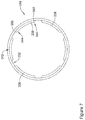
- FIG. 2 shows a cross-sectional view along line 2 - 2 of FIG. 1 .
- FIG. 2 illustrates a cross-section taken along the distal section 18 of the tubular member 14 .
- FIG. 2 represents a cross-section of tubular member 14 in an unexpanded configuration.
- the distal section 18 of the tubular member 14 may include an outer diameter depicted as “Y.” Further, the distal section 18 of the tubular member 14 may include an inner radial extent (measured from the central longitudinal axis 35 of the distal section 18 to the inner surface 32 of the distal section 18 ) depicted as “X.” Additionally, FIG. 2 shows that distal section 18 of the tubular member 14 may include a wall thickness “W” defined as width of the tubular wall between the inner surface 32 and outer surface 36 of the distal section 18 of tubular member 14 .
- FIG. 2 further illustrates the plurality of reinforcement members 38 positioned within the wall 33 of the distal section 18 of the tubular member 14 .
- FIG. 2 shows six reinforcement members 38 positioned circumferentially around the longitudinal axis 35 of the distal section 18 of the tubular member 14 .
- FIG. 2 shows six reinforcement members 38 positioned around the longitudinal axis 35 of the distal section 18 of the tubular member 14 , it is contemplated that more greater or less than six reinforcement members 38 may be utilized for any example introducers 10 contemplated herein.
- tubular member 14 may include 1, 2, 3, 4, 5, 6, 7, 8, 9, 10, 15 or more reinforcement members 38 positioned along tubular member 14 .
- the reinforcement members 38 may include one or more materials (e.g., nylon, Vestamid®, polyimide, polyester, metals, etc.) which are stiffer, higher durometer materials than the material for which the distal section 18 of the tubular member 14 is constructed.
- materials e.g., nylon, Vestamid®, polyimide, polyester, metals, etc.
- FIG. 2 shows that in some examples, the width of reinforcement members 38 may be substantially uniform. In other words, the width of reinforcement members 38 may remain substantially uniform along the length distal section 18 . However, it is contemplated that the width of one or more of the reinforcement members 38 may taper along the distal section 18 of the tubular member 14 (e.g., taper toward the tip member 56 ).
- Each of the reinforcement members 38 shown in FIG. 2 may include an inwardly-facing surface 40 , an outwardly-facing surface 42 and two end surfaces 44 . Further, FIG. 2 shows that the inner surface 40 of each of the reinforcement members 38 may be positioned radially outward of the inner surface 32 of the distal section 18 of the tubular member 14 . Further, the outer surface 42 of each of the reinforcement members 38 may be positioned radially inward of the outer surface 36 of the distal section 18 of the tubular member 14 . In other words, each of the reinforcement members 38 may be embedded (e.g., encased, surrounded, etc.) within the wall thickness “W” of the distal section 18 of the tubular member 14 .
- FIG. 2 illustrates that each of the reinforcement members 38 may be circumferentially spaced apart from one another around the longitudinal axis 35 of the distal section 18 of the tubular member 14 .
- FIG. 2 shows the ends 44 of each of the reinforcement members 38 may be spaced apart from one another a distance depicted as “D” in FIG. 2 .
- the reinforcement members 38 may be spaced substantially equidistant from one another. In other words, the spacing “D” may be substantially equivalent between individual adjacent reinforcement members 38 .
- reinforcement members 38 may be spaced at variable distances around the longitudinal axis 35 .
- the distance “D” depicted in FIG. 2 may vary along the wall thickness of distal section 18 . For example, the distance “D” may increase as it is measured from an end 44 of a reinforcement member 38 to an adjacent end 44 of an adjacent reinforcement member 38 .
- introducer 10 it may be desirable to design introducer 10 to permit a medical device (e.g., heart valve) to pass therethrough.
- a medical device e.g., heart valve
- FIG. 3 represents the distal section 18 of tubular member 14 in an expanded configuration.
- FIG. 3 may represent the cross-section of the tubular member 14 shown in FIG. 2 after it has been expanded radially outward. Stated another way, the distal section 18 of the tubular member 14 may shift from a first position to a second position.
- the first configuration may represent an unexpanded configuration while the second configuration may represent an expanded configuration.
- the distal section 18 of the tubular member 14 may include an outer diameter depicted as “Y 2 .” It can be appreciated that the expanded outer diameter Y 2 may be greater than the unexpanded diameter Y shown in FIG. 2 . Further, the distal section 18 of the tubular member 14 may include an expanded inner radial extent (measured from the central longitudinal axis 35 of the distal section 18 to the inner surface 32 of the distal section 18 ) depicted as “X 2 .” It can be appreciated that the expanded inner radius X 2 may be greater than the unexpanded inner radius X shown in FIG. 2 .
- the wall thickness of the distal section 18 and/or the thickness of the reinforcement members 38 may decrease.
- the material defining the distal section 18 and/or one or more of the reinforcement members 38 may stretch as the distal section 18 of the tubular member 14 expands radially outward. This stretching of the distal section 18 of the tubular member 14 may cause the wall thickness of the distal section 18 to decrease.
- FIG. 3 shows the wall thickness of the expanded distal section 18 depicted as “W 2 .”
- Wall thickness W 2 represents the wall thickness of the expanded distal section 18 of tubular member 14 .
- FIG. 3 shows wall thickness W 2 taken along the portion of the cross-section of the distal section 18 which includes the reinforcement members 38 .
- wall thickness W 2 represents the wall thickness of the portion of the tubular wall of distal section 18 that includes one of the reinforcement members 38 .
- the expanded distal section 18 of tubular member 14 may include a third wall thickness.
- FIG. 3 illustrates a wall thickness depicted as “W 3 ” taken along the portion of the cross-section of the distal section 18 which does not include the reinforcement members 38 .
- FIG. 3 shows the space between each of the reinforcement members 38 as “D 2 .” It can be appreciated that as the distal section 18 of tubular member 14 expands, the space between adjacent reinforcement members 38 may increase. In other words, the space D 2 may be greater than D (depicted in FIG. 2 ).
- FIG. 3 illustrates that wall thickness W 3 may be less than wall thickness W 2 .
- the portion of the wall of the distal section 18 of the tubular member 14 may taper down (e.g., neck down) around the ends 44 of the reinforcement members 38 .
- FIG. 3 shows that the wall thickness of the distal section 18 of the tubular member 14 may include tapered sections 46 .
- the tapered sections 46 may be defined as a transition region from wall thickness W 2 to wall thickness W 3 .
- the distal section 18 of tubular member 14 may include a second expanded inner radial extent (measured from the central longitudinal axis 35 of the distal section 18 to the inner surface 32 positioned along distance D 2 described above) depicted as “X 3 .” It can be appreciated that the second expanded inner radius X 3 may be greater than the expanded inner radius X 2 illustrated in FIG. 3 .
- FIG. 4 illustrates a cross-section of another example expanded distal section 118 of tubular member 14 .
- Distal section 118 may be similar in form and function to other examples disclosed herein.
- distal section 118 may include an outer diameter Y 2 which may match the expanded outer diameter depicted in FIG. 3 .
- FIG. 4 further illustrates that distal section 118 may include a second outer diameter depicted as “Y 3 .” It can be appreciated that the second outer diameter Y 3 may be less than the outer diameter Y 2 .
- the outer surface 134 of the distal section 118 may taper down radially inward around the ends 144 of the reinforcement members 138 .
- the wall thickness of the distal section 118 of the tubular member 14 may include tapered sections 146 located on the inner surface 132 of the distal section 118 and also may include tapered sections 147 located on the outer surface 134 of the distal section 118 .
- the tapered sections 147 may be defined as a transition region from outer diameter Y 2 to outer diameter Y 3 .
- FIG. 5 illustrates another example distal section 218 of tubular member 14 in a first or unexpanded configuration.
- Distal section 218 may be similar in form and function to other distal sections described herein.
- distal section 218 illustrates than in some examples, one or more of the reinforcement members 238 may be positioned along the inner surface 232 of distal section 218 .
- the outer surface 242 of one or more of the reinforcement members 238 may be attached to the inner surface 232 of distal section 218 .
- the reinforcement members 238 may be circumferentially spaced from one another around the inner surface 232 of distal section 218 .
- each of the reinforcement members 238 may be spaced substantially equidistant from one another around the inner surface 232 of distal section 218 . However, it is further contemplated that reinforcement members 238 may be spaced at variable distances around longitudinal axis 235 .
- the distal section 218 of the tubular member 14 shown in FIG. 5 may include an outer diameter depicted as “Y 4 .”
- FIG. 5 illustrates that each of the reinforcement members 238 may be circumferentially spaced apart from one another around the longitudinal axis 235 of the distal section 218 of the tubular member 14 .
- FIG. 5 shows the reinforcement members 238 may be spaced apart from one another a distance depicted as “D 3 ” in FIG. 5 .
- the reinforcement members 238 may be spaced substantially equidistant from one another. In other words, the spacing “D 3 ” may be substantially equivalent between individual reinforcement members 238 .
- reinforcement members 238 may be spaced at variable distances around longitudinal axis 235 . Additionally, it can be appreciated that the distance “D 3 ” depicted in FIG. 5 may vary along the wall thickness of distal section 218 .
- FIG. 6 represents the distal section 218 of tubular member 14 in a second or expanded configuration.
- FIG. 6 may represent the cross-section of the distal section 218 shown in FIG. 5 after it has been expanded radially outward.
- the distal section 218 of the tubular member 14 may include an outer diameter depicted as “Y 5 .” It can be appreciated that the expanded outer diameter Y 5 may be greater than the unexpanded diameter Y 4 shown in FIG. 5 .
- the wall thickness of the distal section 218 and/or the thickness of the reinforcement members 238 may decrease.
- the material defining the distal section 218 and/or one or more of the reinforcement members 238 may stretch as the distal section 218 of the tubular member 14 expands radially outward. This stretching of the distal section 218 of the tubular member 14 may cause the wall thickness of the distal section 218 to decrease.
- FIG. 6 shows the space between each of the reinforcement members 238 as “D 4 .” It can be appreciated that as the distal section 218 of tubular member 14 expands, the space between adjacent reinforcement members 238 may increase. In other words, the space D 4 may be greater than D 3 (depicted in FIG. 5 ).
- FIG. 7 illustrates another example distal section 318 of tubular member 14 .
- Distal section 318 may be similar in form and function to other distal sections described herein.
- distal section 318 illustrates that in some examples, one or more of the reinforcement members 338 may be positioned along the inner surface 332 of distal section 318 .
- the outer surface 342 of one or more of the reinforcement members 338 may be attached to the inner surface 332 of distal section 318 .
- the reinforcement members 338 may be circumferentially spaced from one another around the inner surface 332 of distal section 318 .
- each of the reinforcement members 338 may be spaced substantially equidistant from one another around the inner surface 332 of distal section 318 .
- distal section 318 illustrates that one or more of reinforcement members 338 may include end portions 344 having a curved shape 350 .
- FIG. 7 shows the end portions 344 having a rounded or curved shape 350 .
- This curved or rounded shape 350 may reduce the surface area that contacts a medical device which may be passed through distal section 318 .
- tubular member 14 may include one or more layers or coatings, such as a lubricious coating, a hydrophilic coating, a hydrophobic coating, or other suitable coatings, and the like, or may include a lubricant disposed thereon.
- a liner may be disposed along the inner surface of tubular member 14 . It is further contemplated that the liner may extend along the length of tubular member 14 , for example, the liner may extend along the distal section 14 , the proximal section 16 or both the distal section 14 and the proximal section 16 .
- the example expandable introducer 10 may be disposed about or inserted over a guidewire (not shown), although the guidewire is not required.
- the expandable introducer 10 may include a proximal section 16 and a distal section 18 .
- the proximal section 16 may have an inner diameter or extent sufficient to accept a medical device passing therethrough, while the distal expandable section 18 may have an inner diameter or radial extent in a relaxed condition that is less than a maximum outer diameter or extent of the medical device.
- the expandable introducer 10 may be formed using any of the techniques or structures discussed herein.
- FIGS. 8-10 illustrate a method of use of introducer 10 .
- FIG. 8 shows that an elongate medical device 52 (e.g., heart valve) may be inserted into the lumen 22 of the introducer 10 and advanced distally toward the distal end of introducer 10 .
- the medical device may exert a radially outward force from within the lumen 22 upon the wall of the tubular member 14 .
- the radially outward force may cause the tubular member 14 to expand as the medical device 52 is advanced distally through the proximal section 16 and/or the distal section 18 .
- FIG. 9 illustrates the medical device 52 being inserted through proximal section 16 and into the distal section 18 .
- the distal section 18 may expand radially outward as the medical device 52 is inserted therethrough.
- FIG. 10 illustrates the medical device 52 being positioned within the distal section 18 of introducer 10 .
- the distal section 18 may expand radially outward in order to permit medical device 52 to travel therethrough.
- FIG. 10 illustrates distal section 18 contracting (e.g., returning) to an unexpanded diameter as the medical device 52 travels therethrough.
- the distal section 18 of introducer 10 may be designed such that it can expand radially outward and then contract radially inward as medical devices are inserted therethrough.
- the expansion of the distal section 18 from an unexpanded configuration to an expanded configuration illustrated in FIG. 10 may correspond to the expansion from an unexpanded to an expanded configuration of the tubular members illustrated and described above with respect to FIG. 2-7 .
- the expansion of the distal section 18 of the medical device shown in FIG. 10 from an unexpanded configuration to an expanded configuration may be variable.
- the diameter of the unexpanded distal section 18 of the medical device 10 may increase to an expanded diameter, after which, it may contract to a diameter that is greater than the diameter of the unexpanded configuration.
- this is not intended to be limiting. It is contemplated that once the unexpanded distal section 18 is expanded, it may remain expanded or it may return to any diameter less than the expanded diameter (including a diameter that is less than the unexpanded diameter).
- introducer 10 may be made from materials such as metals, metal alloys, polymers, ceramics, metal-polymer composites, or other suitable materials, and the like.
- suitable materials may include metallic materials such as stainless steels (e.g. 304v stainless steel or 316L stainless steel), nickel-titanium alloys (e.g., nitinol, such as super elastic or linear elastic nitinol), nickel-chromium alloys, nickel-chromium-iron alloys, cobalt alloys, nickel, titanium, platinum, or alternatively, a polymeric material, such as a high performance polymer, or other suitable materials, and the like.
- stainless steels e.g. 304v stainless steel or 316L stainless steel
- nickel-titanium alloys e.g., nitinol, such as super elastic or linear elastic nitinol
- nickel-chromium alloys nickel-chromium-iron alloys
- cobalt alloys nickel, titanium, platinum, or alternatively
- nitinol was coined by a group of researchers at the United States Naval Ordinance Laboratory (NOL) who were the first to observe the shape memory behavior of this material.
- NOL United States Naval Ordinance Laboratory
- the word nitinol is an acronym including the chemical symbol for nickel (Ni), the chemical symbol for titanium (Ti), and an acronym identifying the Naval Ordinance Laboratory (NOL).
- the introducer 10 may be made from materials such as, for example, a polymeric material, a ceramic, a metal, a metal alloy, a metal-polymer composite, or the like.
- suitable polymers may include polyurethane, a polyether-ester such as ARNITEL® available from DSM Engineering Plastics, a polyester such as HYTREL® available from DuPont, a linear low density polyethylene such as REXELL®, a polyamide such as DURETHAN® available from Bayer or CRISTAMID® available from Elf Atochem, an elastomeric polyamide, a block polyamide/ether, a polyether block amide such as PEBA available under the trade name PEBAX®, silicones, polyethylene, Marlex high-density polyethylene, polyetheretherketone (PEEK), polyimide (PI), and polyetherimide (PEI), a liquid crystal polymer (LCP) alone or blended with other materials.
- a polymeric material such as, for example, a polymeric
- a suitable polymeric material may have a yield strain of at least 20%, at least 30%, at least 40%, at least 50%, or more.
- the sheath, the membrane, and/or the plurality of corrugations may be made from a material having a low coefficient of friction.
- the sheath, the membrane, and/or the plurality of corrugations may be formed from a fluoropolymer, such as polytetrafluoroethylene (PTFE) or fluorinated ethylene propylene (FEP).
- PTFE polytetrafluoroethylene
- FEP fluorinated ethylene propylene
- Portions of introducer 10 may be made of, may be doped with, may include a layer of, or otherwise may include a radiopaque material.
- Radiopaque materials are understood to be materials capable of producing a relatively bright image on a fluoroscopy screen or another imaging technique such as X-ray during a medical procedure. This relatively bright image aids the user of device in determining its location.
- one or more of the elements described above i.e., the sheath, the membrane, the medical device, etc.
- Suitable materials can include, but are not limited to, bismuth subcarbonate, iodine, gold, platinum, palladium, tantalum, tungsten or tungsten alloy, and the like.
- devices and methods in accordance with the disclosure can be adapted and configured for use in other parts of the anatomy of a patient.
- devices and methods in accordance with the disclosure can be adapted for use in the digestive or gastrointestinal tract, such as in the mouth, throat, small and large intestine, colon, rectum, and the like.
- devices and methods can be adapted and configured for use within the respiratory tract, such as in the mouth, nose, throat, bronchial passages, nasal passages, lungs, and the like.
- the devices and methods described herein with respect to percutaneous deployment may be used in other types of surgical procedures as appropriate.
- the devices may be deployed in a non-percutaneous procedure.
- Devices and methods in accordance with the disclosure can also be adapted and configured for other uses within the anatomy.
Abstract
Description
-
- a hub;
- a transition member having a proximal portion, a distal portion and a constant outer diameter from the distal portion to the proximal portion; and
- an expandable member having a proximal portion and a distal portion, the proximal portion of the expandable member coupled to the distal portion of the transition member;
- wherein the proximal portion of the transition member is coupled to a distal portion of the hub member;
- wherein the expandable member further includes a plurality of spine members spaced around a longitudinal axis of the expandable member; and
Claims (10)
Priority Applications (1)
| Application Number | Priority Date | Filing Date | Title |
|---|---|---|---|
| US15/874,056 US11076884B2 (en) | 2017-01-18 | 2018-01-18 | Introducer with expandable capabilities |
Applications Claiming Priority (2)
| Application Number | Priority Date | Filing Date | Title |
|---|---|---|---|
| US201762447543P | 2017-01-18 | 2017-01-18 | |
| US15/874,056 US11076884B2 (en) | 2017-01-18 | 2018-01-18 | Introducer with expandable capabilities |
Publications (2)
| Publication Number | Publication Date |
|---|---|
| US20180199960A1 US20180199960A1 (en) | 2018-07-19 |
| US11076884B2 true US11076884B2 (en) | 2021-08-03 |
Family
ID=61768388
Family Applications (1)
| Application Number | Title | Priority Date | Filing Date |
|---|---|---|---|
| US15/874,056 Active 2038-07-14 US11076884B2 (en) | 2017-01-18 | 2018-01-18 | Introducer with expandable capabilities |
Country Status (4)
| Country | Link |
|---|---|
| US (1) | US11076884B2 (en) |
| EP (1) | EP3570926B1 (en) |
| CN (1) | CN110461399B (en) |
| WO (1) | WO2018136589A2 (en) |
Families Citing this family (13)
| Publication number | Priority date | Publication date | Assignee | Title |
|---|---|---|---|---|
| US8790387B2 (en) | 2008-10-10 | 2014-07-29 | Edwards Lifesciences Corporation | Expandable sheath for introducing an endovascular delivery device into a body |
| US10792471B2 (en) | 2015-04-10 | 2020-10-06 | Edwards Lifesciences Corporation | Expandable sheath |
| US10327896B2 (en) | 2015-04-10 | 2019-06-25 | Edwards Lifesciences Corporation | Expandable sheath with elastomeric cross sectional portions |
| US10548631B2 (en) | 2016-03-04 | 2020-02-04 | Boston Scientific Scimed Inc. | Introducer with expandable capabilities |
| US10912919B2 (en) | 2017-01-23 | 2021-02-09 | Edwards Lifesciences Corporation | Expandable sheath |
| US10799685B2 (en) | 2017-03-09 | 2020-10-13 | Edwards Lifesciences Corporation | Expandable sheath with longitudinally extending reinforcing members |
| US11129959B2 (en) | 2018-02-15 | 2021-09-28 | Boston Scientific Scimed, Inc. | Introducer with expandable capabilities |
| JP2021520873A (en) | 2018-04-09 | 2021-08-26 | エドワーズ ライフサイエンシーズ コーポレイションEdwards Lifesciences Corporation | Expandable sheath |
| US11786695B2 (en) | 2018-07-25 | 2023-10-17 | Edwards Lifesciences Corporation | Methods of making an expandable sheath |
| EP4129382A1 (en) | 2018-09-10 | 2023-02-08 | Boston Scientific Scimed, Inc. | Introducer with expandable capabilities |
| CA3173070A1 (en) * | 2020-02-27 | 2021-09-02 | Edwards Lifesciences Corporation | Expandable sheath with extruded segments |
| WO2023177684A1 (en) * | 2022-03-15 | 2023-09-21 | Cue Health Inc. | Sample collection device |
| WO2023212766A1 (en) * | 2022-05-04 | 2023-11-09 | Three Peaks Medical Pty Ltd | Improvements to introducer sheaths |
Citations (7)
| Publication number | Priority date | Publication date | Assignee | Title |
|---|---|---|---|---|
| US5320611A (en) | 1993-02-04 | 1994-06-14 | Peter M. Bonutti | Expandable cannula having longitudinal wire and method of use |
| US20080004571A1 (en) | 2006-06-28 | 2008-01-03 | Abbott Laboratories | Expandable introducer sheath |
| US20100198160A1 (en) | 2006-06-28 | 2010-08-05 | Abbott Vascular Inc. | Expandable Introducer Sheaths and Methods for Manufacture and Use |
| US7837692B2 (en) | 1999-01-28 | 2010-11-23 | Salviac Limited | Catheter with an expandable end portion |
| EP2995268A1 (en) | 2014-09-12 | 2016-03-16 | Freudenberg Medical, LLC | An expandable introducer sheath |
| US20160095622A1 (en) * | 2014-10-02 | 2016-04-07 | Boston Scientific Scimed, Inc. | Expandable access shealth |
| WO2016164082A1 (en) | 2015-04-10 | 2016-10-13 | Edwards Lifesciences Corporation | Expandable sheath with elastomeric cross sectional portions |
Family Cites Families (3)
| Publication number | Priority date | Publication date | Assignee | Title |
|---|---|---|---|---|
| US8801744B2 (en) * | 2006-06-28 | 2014-08-12 | Abbott Laboratories | Expandable introducer sheath to preserve guidewire access |
| US9861431B2 (en) * | 2013-03-13 | 2018-01-09 | Kyphon SÀRL | Radiofrequency inflatable device |
| EP3035990B1 (en) * | 2013-08-23 | 2019-05-22 | Boston Scientific Scimed, Inc. | Catheters and catheter shafts |
-
2018
- 2018-01-18 EP EP18713392.1A patent/EP3570926B1/en active Active
- 2018-01-18 CN CN201880018917.0A patent/CN110461399B/en active Active
- 2018-01-18 WO PCT/US2018/014147 patent/WO2018136589A2/en unknown
- 2018-01-18 US US15/874,056 patent/US11076884B2/en active Active
Patent Citations (8)
| Publication number | Priority date | Publication date | Assignee | Title |
|---|---|---|---|---|
| US5320611A (en) | 1993-02-04 | 1994-06-14 | Peter M. Bonutti | Expandable cannula having longitudinal wire and method of use |
| US7837692B2 (en) | 1999-01-28 | 2010-11-23 | Salviac Limited | Catheter with an expandable end portion |
| US20080004571A1 (en) | 2006-06-28 | 2008-01-03 | Abbott Laboratories | Expandable introducer sheath |
| US20100198160A1 (en) | 2006-06-28 | 2010-08-05 | Abbott Vascular Inc. | Expandable Introducer Sheaths and Methods for Manufacture and Use |
| EP2995268A1 (en) | 2014-09-12 | 2016-03-16 | Freudenberg Medical, LLC | An expandable introducer sheath |
| US20160095622A1 (en) * | 2014-10-02 | 2016-04-07 | Boston Scientific Scimed, Inc. | Expandable access shealth |
| WO2016164082A1 (en) | 2015-04-10 | 2016-10-13 | Edwards Lifesciences Corporation | Expandable sheath with elastomeric cross sectional portions |
| US20160296332A1 (en) | 2015-04-10 | 2016-10-13 | Edwards Lifesciences Corporation | Expandable sheath with elastomeric cross sectional portions |
Non-Patent Citations (1)
| Title |
|---|
| Invitation to Pay Additional Fees dated Jul. 2, 2018 for International Application No. PCT/US2018/014147. |
Also Published As
| Publication number | Publication date |
|---|---|
| EP3570926B1 (en) | 2021-07-07 |
| CN110461399A (en) | 2019-11-15 |
| WO2018136589A3 (en) | 2018-09-27 |
| US20180199960A1 (en) | 2018-07-19 |
| CN110461399B (en) | 2022-03-29 |
| EP3570926A2 (en) | 2019-11-27 |
| WO2018136589A2 (en) | 2018-07-26 |
Similar Documents
| Publication | Publication Date | Title |
|---|---|---|
| US11076884B2 (en) | Introducer with expandable capabilities | |
| US10751178B2 (en) | Introducer with expandable capabilities | |
| US20210162171A1 (en) | Fully compliant large bore expandable sheath | |
| US20180326186A1 (en) | Expandable sheath | |
| EP2779911B1 (en) | Vessel protection membrane | |
| US20180325548A1 (en) | Introducer with expandable capabilities | |
| US11191927B2 (en) | Dilator with engagement region | |
| US11129959B2 (en) | Introducer with expandable capabilities | |
| US20190083082A1 (en) | Introducer with expandable capabilities | |
| US8740842B2 (en) | Kerstpiek tip for medical devices | |
| US10959869B2 (en) | Introducer with expandable capabilities |
Legal Events
| Date | Code | Title | Description |
|---|---|---|---|
| AS | Assignment |
Owner name: BOSTON SCIENTIFIC SCIMED, INC, MINNESOTA Free format text: ASSIGNMENT OF ASSIGNORS INTEREST;ASSIGNORS:ANDERSON, JAMES M.;GROVENDER, ADAM DAVID;REYNOLDS, BRIAN R.;AND OTHERS;REEL/FRAME:044656/0273 Effective date: 20180117 |
|
| FEPP | Fee payment procedure |
Free format text: ENTITY STATUS SET TO UNDISCOUNTED (ORIGINAL EVENT CODE: BIG.); ENTITY STATUS OF PATENT OWNER: LARGE ENTITY |
|
| STPP | Information on status: patent application and granting procedure in general |
Free format text: DOCKETED NEW CASE - READY FOR EXAMINATION |
|
| STPP | Information on status: patent application and granting procedure in general |
Free format text: NON FINAL ACTION MAILED |
|
| STPP | Information on status: patent application and granting procedure in general |
Free format text: RESPONSE TO NON-FINAL OFFICE ACTION ENTERED AND FORWARDED TO EXAMINER |
|
| STPP | Information on status: patent application and granting procedure in general |
Free format text: FINAL REJECTION MAILED |
|
| STPP | Information on status: patent application and granting procedure in general |
Free format text: ADVISORY ACTION MAILED |
|
| STPP | Information on status: patent application and granting procedure in general |
Free format text: DOCKETED NEW CASE - READY FOR EXAMINATION |
|
| STPP | Information on status: patent application and granting procedure in general |
Free format text: RESPONSE TO NON-FINAL OFFICE ACTION ENTERED AND FORWARDED TO EXAMINER |
|
| STPP | Information on status: patent application and granting procedure in general |
Free format text: NOTICE OF ALLOWANCE MAILED -- APPLICATION RECEIVED IN OFFICE OF PUBLICATIONS |
|
| STPP | Information on status: patent application and granting procedure in general |
Free format text: AWAITING TC RESP., ISSUE FEE NOT PAID |
|
| STPP | Information on status: patent application and granting procedure in general |
Free format text: NOTICE OF ALLOWANCE MAILED -- APPLICATION RECEIVED IN OFFICE OF PUBLICATIONS |
|
| STPP | Information on status: patent application and granting procedure in general |
Free format text: PUBLICATIONS -- ISSUE FEE PAYMENT VERIFIED |
|
| STCF | Information on status: patent grant |
Free format text: PATENTED CASE |